US10463529B2 - Device and method for deterring back-lying snoring posture - Google Patents
Device and method for deterring back-lying snoring posture Download PDFInfo
- Publication number
- US10463529B2 US10463529B2 US14/325,473 US201414325473A US10463529B2 US 10463529 B2 US10463529 B2 US 10463529B2 US 201414325473 A US201414325473 A US 201414325473A US 10463529 B2 US10463529 B2 US 10463529B2
- Authority
- US
- United States
- Prior art keywords
- dome
- annulus
- person
- skin
- human subject
- Prior art date
- Legal status (The legal status is an assumption and is not a legal conclusion. Google has not performed a legal analysis and makes no representation as to the accuracy of the status listed.)
- Active, expires
Links
Images


Classifications
-
- A—HUMAN NECESSITIES
- A61—MEDICAL OR VETERINARY SCIENCE; HYGIENE
- A61F—FILTERS IMPLANTABLE INTO BLOOD VESSELS; PROSTHESES; DEVICES PROVIDING PATENCY TO, OR PREVENTING COLLAPSING OF, TUBULAR STRUCTURES OF THE BODY, e.g. STENTS; ORTHOPAEDIC, NURSING OR CONTRACEPTIVE DEVICES; FOMENTATION; TREATMENT OR PROTECTION OF EYES OR EARS; BANDAGES, DRESSINGS OR ABSORBENT PADS; FIRST-AID KITS
- A61F5/00—Orthopaedic methods or devices for non-surgical treatment of bones or joints; Nursing devices; Anti-rape devices
- A61F5/56—Devices for preventing snoring
Landscapes
- Health & Medical Sciences (AREA)
- Otolaryngology (AREA)
- Pulmonology (AREA)
- Nursing (AREA)
- Orthopedic Medicine & Surgery (AREA)
- Engineering & Computer Science (AREA)
- Biomedical Technology (AREA)
- Heart & Thoracic Surgery (AREA)
- Vascular Medicine (AREA)
- Life Sciences & Earth Sciences (AREA)
- Animal Behavior & Ethology (AREA)
- General Health & Medical Sciences (AREA)
- Public Health (AREA)
- Veterinary Medicine (AREA)
- Orthopedics, Nursing, And Contraception (AREA)
Abstract
Domed articles are disclosed with reinforcements and adaptations for adhesively-applying them to a person's back while sleeping, to deter against the person sleeping supinely on their back, a posture that is commonly associated with louder and more dangerous snoring. The dome-like articles (1) are typically shaped like a campaign hat in that they have a central dome (or crown region) surrounded by a concentric, relatively-flat annular perimeter (or brim region), (2) have a hypoallergenic adhesive on a flat side of the brim—the side facing the person's back—for removably securing the domed article to the person's back, (3) are typically formed from a unitary plastic sheet with complex shapes and surface features that reinforce the strength of the dome to resist collapse when the person rolls onto it, such shapes and features including stress distributors and structural reinforcements such as intersecting arcuate ridges and/or troughs, and (4) have holes or other surface features to allow for ventilation of the space enclosed between the dome and the person's back.
Description
The present application claims the benefit of previously filed U.S. Provisional Application, Ser. No. 61/555,501, filed Nov. 4, 2011, U.S. Non-Provisional patent application Ser. No. 13/669,161, filed Nov. 5, 2012, as well as U.S. Provisional Application, Ser. No. 62/002,258, filed May 23, 2014. By this reference, the full disclosure, including the claims and drawings, of U.S. Provisional Application, Ser. No. 61/555,501, U.S. Non-Provisional application Ser. No. 13/669,161, and U.S. Provisional Application, Ser. No. 62/002,258, are incorporated herein as though now set forth in their entirety.
This is a Non-Provisional patent application filed under 37 CFR 1.53(b) and is submitted with an accompanying non-publication request in accordance with 35 U.S.C. § 122(b). Accordingly, the subject matter of this application is to be maintained in secrecy until and unless Applicant files another application claiming its priority and/or allows an application to publish based on this application.
The present invention relates to the field of body positioning aids for encouraging the human body to assume a safe and healthy posture while sleeping and, more particularly, for encouraging a posture that tends to minimize snoring for people who tend to snore.
Snoring, needless to say, can be annoying to others in the same bed, to others in the same house, and occasionally even to others living next door. The health of those who snore can also be at serious risk—not just when they get kicked, shoved or smothered by their sleeping companions—but often due to sleep apnea and/or reduced blood-oxygen levels that may be associated with snoring.
It has long been known that many people snore more commonly or more loudly and dangerously when they sleep lying on their backs. Snoring and obstructive sleep apnea are at much greater risk when they sleep on their backs, largely because the tongue and the muscles and surrounding tissue in the throat typically relax during sleep. When people are in a relaxed sleep state, if they are already on their back or if they roll or move onto their back, the relaxed tongue and throat tissue tends to slump backwards to partially block the airway to their lungs. The air they are breathing necessarily speeds up as it moves through the smaller, blocked opening of the airway, and the fast-moving air then causes the loose surrounding tissue to vibrate, which causes the noise that we call snoring. As a result, those who live with loud snorers quickly learn to nudge the snorer into another position in order to stop or reduce the snoring.
Likewise, numerous innovative problem solvers have developed devices and methods for keeping people from sleeping on their backs and from rolling or moving into a back-lying position while they sleep. Perhaps most famous, many have long known about the approach of sewing a tennis ball into the pocket of a T-shirt and having a snorer wear the tennis ball shirt backwards when they sleep, which keeps them off their back because it is uncomfortable to sleep on a tennis ball. Many others have long tried to resolve snoring challenges with variations on that ancient ball-sewn-in-a-pocket concept, such as is shown, for example, in U.S. Pat. Nos. 2,304,235 and 5,893,365.
Unfortunately, despite that problems with snoring have been common since the dawn of time, and despite that many have long been trying to resolve such problems, few have succeeded in developing an affordable solution that works well on a consistent basis.
Reference is made first to FIG. 1 which provides a perspective view of a preferred embodiment of the device of the present invention constructed from a unitary molded plastic material. In the perspective view of FIG. 1 , the various external features of the device are disclosed. Supine-deterrent 10 is generally seen to be a hat-shaped device, shaped similar to a campaign hat, sized and configured to be removably placed on the back of the person.
As described above, the basic purpose of the device is to consciously or subconsciously deter the person from sleeping on the person's back, a position which tends to increase the incidence and severity of snoring. Because snoring while sleeping is frequently associated with the orientation of the sleeper on the sleeper's back, the device of the present invention serves as a manner of reducing the incidence of snoring while sleeping. The structure of supine-deterrent 10 provides just enough of a conscious or subconscious distraction or discomfort as to cause the person to move into a position where such discomfort no longer exists or occurs. In general, this means moving from a position where the person's back is against the relatively firm surface of the sleeping platform (mattress) to a position where such contact is not being made. Further details regarding this functionality are described in conjunction with FIGS. 7A and 7B below.
Extending concentrically within contact annulus 12 is reinforced dome region 14 of supine-deterrent 10. The dome region 14 in FIG. 1 is a generally spherical section, whereby the walls converge such that the space defined by the walls reduces at further distance from the relatively larger opening near the base of the dome. Those skilled in the art will recognize that the dome may not just be a spherical section but may also have other non-spherical shapes whereby the walls converge in an analogous manner. In the alternative embodiment shown in FIGS. 5 and 8-11 , the dome may generally be shaped as an ovoid surface such that its walls 826 and 828 generally converge toward one another at distances further from its base 512. In still another alternative embodiment (not shown), the dome may be shaped as, or may include, a frustoconical shape wherein the walls of the dome analogously converge toward one another in linear relationship to the distance from the dome's base. A rectangular pyramid shape is used in further alternatives whereby the walls analogously converge toward one another in linear relationship to the distance from the dome's base and define a rectangular shape. Still other alternatives use other irregular shapes such that all the walls of the irregular shape analogously converge toward each other in linear relationship to the distance from the base of the dome structure.
For structural reinforcement of the dome shape, positioned near the center of reinforced dome region 14, are arcuate ridges 18 a-18 d. In the preferred embodiment of the present invention, arcuate ridges 18 a-18 d comprise long cylindrical convex elevations that together form a cross-shaped eminence centered on the apex of reinforced dome region 14 of the device. These arcuate ridges 18 a-18 d primarily provide structural strength to the dome shape of the device. Without such changes in the plane of the surface orientation, and therefore the wall structure of the dome-shaped device, there would be a tendency for the dome shape to collapse when a direct force might be exerted on the apex of the dome. Arcuate ridges 18 a-18 d, structured as shown, provide multi-directional structural support to what otherwise would be a flat or simple curve wall structure.
Flat ridges 19 a-19 d are orthogonally arranged around the upper surface of contact annulus 12. These flat ridges 19 a-19 d provide further structural support for reinforced dome region 14. Flat ridges 19 a-19 d are generally rectangular in shape and their raised character form airflow apertures 360, positioned along the lower surface of contact annulus 12 and described in further detail below.
The device of the present invention is preferably molded from a lightweight but resilient plastic material, being die-stamped on a punch press from sheet stock of amorphous polyethylene terephthalate (APET) with a thickness of 0.0175 inches. Examples of other suitable plastics include high-density polyethylene (HDPE), polyvinyl chloride (PVC), low density polyethylene (LDPE), polypropylene (PP), high impact polystyrene (HIPS), acrylonitrile butadiene styrene (ABS), polycarbonate (PC), and polycarbonate/acrylonitrile butadiene styrene (PC/ABS). The important aspects of the material for purposes of the present invention are its weight and rigidity. The material should also have enough bending plasticity (i.e. not be brittle) to prevent the formation of sharp edges or cracking even under excessive crushing force. Additionally, the material should be resilient such that, in the event of collapse under force, the dome shape tends to flex back.
Reference is next made to FIG. 3 which provides a side elevational view of the preferred embodiment of the device of the present invention showing in profile the elevational configuration of the device and the various sections of its domed structure as described above. Supine-deterrent 10 is seen to comprise contact annulus 12 and reinforced dome region 14. Reinforced dome region 14 is made up primarily of dome base walls 26, dome top wall 28 and dome intermediate wall 30. Dome intermediate wall 30 presents a more convex surface than dome top wall 28. It is recognized that each of these various regions and sections of the overall hat-shaped domed structure provide some particular function with regard to rigidity and durability.
Associated with contact annulus 12 is perimeter flange 22 which extends beyond the edge of contact annulus 12. Perimeter flange 22 provides a benefit when removing supine-deterrent 10 by presenting a lip for the person to grasp. In conjunction with contact annulus 12, perimeter flange 22 provides strength and presents a relatively flat bottom surface that is more favorable for skin contact, thereby separating the thin edge of the perimeter from the skin.
Although not shown well in FIG. 3 , the transitions between perimeter flange 22 and contact annulus 12, as well between contact annulus 12 and the inside of dome base wall 26, include a smooth radius to minimize pressure concentration on the person's skin.
Referring again to FIG. 3 , angle 380 is shown as the angle between the person's back with supine-deterrent 10 attached and dome base wall 26. Angle 380 is an obtuse angle which provides further support for the dome shape of supine-deterrent 10. The converging character (i.e. its conical nature) enhances structural stability such as with heavier subjects and subjects who move frequently during sleep. This converging character also provides benefits that ease manufacturing.
Some appropriate adhesive compounds may provide the ability for re-use of the device with the same adhesive layer without the need for the constant replacement of the adhesive material. Some such medical adhesives are known in the art that allow for the temporary removal of a bandage or the like and its replacement after examination of the skin surface beneath the bandage. Such adhesive materials may be utilized in conjunction with the device of the present invention, up to a period of re-use where adhesive layer 40 might preferably be replaced. Various protective steps may be taken to extend the life of the adhesive material, such as the use of storage sheets that may be placed over the adhesive surface when the device is not in use and removed when the device is to be placed into use.
The device of the present invention may preferably be manufactured and sold in packages of two with each device re-usable for as many as 5-10 days without the need to renew the adhesive. Additional double-sided adhesive foam circular rings may be provided within the package so as to allow the person to renew the adhesive layer and further extend the usable life of the device. Various other methods for renewing the adhesive on the underside of the device are anticipated. Although the device may preferably have a complete circular ring of adhesive on the base, this is not essential and an appropriate level of adhesion may be obtained by a number of adhesive patches spaced about the circular perimeter underside of the device.
Reference is made to FIG. 5 which provides a perspective view of an alternative embodiment of the device of the present invention constructed from a unitary molded plastic material. In the perspective view of FIG. 5 , the various external features of the device are disclosed. Supine-deterrent 10′ is generally seen to be a helmet-shaped device sized and configured to be removably placed on the back of the person. As described above, the purpose of the device is to consciously or subconsciously deter the person from sleeping on their back. Because snoring while sleeping is frequently associated with the orientation of the sleeper on their back, the device of the present invention serves as a manner of reducing the incidence of snoring while sleeping. The structure of supine-deterrent 10′ provides just enough of a conscious or subconscious distraction or discomfort as to cause the person to move into a position where such discomfort no longer exists or occurs. In general, this means moving from a position where the person's back is against the relatively firm surface of the sleeping platform (mattress) to a position where such contact is not being made. Further details regarding this functionality are described in conjunction with FIGS. 7A and 7B below.
Extending concentrically within contact edge region 512 is reinforced dome region 514 of supine-deterrent 10′. On either side of reinforced dome region 514 are positioned grip indentations 516 a and 516 b. Positioned near the center of reinforced dome region 514 are rigidity cross-channels 518 and airflow apertures 520. In an alternative embodiment of the present invention, rigidity cross-channels 518 comprise a long cylindrical indentation channel crossed by a short cylindrical indentation channel that together form a cross-shaped recess centered on the apex of reinforced dome region 514 of the device. These rigidity cross-channels 518 primarily provide structural strength to the dome shape of the device. Without such changes in the plane of the surface orientation, and therefore the wall structure of the dome-shaped device, there would be a tendency for the dome shape to collapse when a direct force might be exerted on the apex of the dome. The channels, structured as shown, provide multi-directional structural support to what otherwise would be a flat or simple curve wall structure.
Referring once again to FIG. 8 , airflow apertures 520, numbering four in an alternative embodiment, are positioned on dome top wall 828 in an equally spaced orthogonal manner that optimizes airflow through the device. This airflow results from the apertures being positioned near the apex of the device (away from the skin surface of the person) in a sufficient number as to allow for ordinary (unforced) airflow from the inside of the device to the outside ambient air.
Reference is next made to FIG. 9 which provides a long axis side elevational view of an alternative embodiment of the device of the present invention showing in profile the elevational configuration of the device and the various sections of its domed structure as described above. Supine-deterrent 10′ is seen to comprise contact edge region 512 and reinforced dome region 514. Contact edge region 512 is made up of perimeter base 822 and perimeter riser 824. Reinforced dome region 514 is made up primarily of dome base walls 826 and dome top wall 828. It is recognized that each of these various regions and sections of the overall helmet-shaped domed structure provide some particular function with regard to rigidity and durability.
Rigidity short channel 832 is visible in this orientation view along the long axis of the oval-shaped supine-deterrent 10′. FIG. 9 also discloses adhesive pad 940 positioned on the underside of perimeter base 822 of contact edge region 512. Adhesive pad 940 represents one of a number of different methods for adhering the supine-deterrent device of the present invention to the back of the person. Adhesive pad 940 may preferably be constructed of a medical skin adhesive compound such as that utilized on bandages and the like, that provides sufficient adhesion to prevent movement or removal of the device from the skin unless a specific and direct force is exerted on the device. In the preferred and alternative embodiments, it is important that the device not slide sideways across the skin of the person and remain positioned both in a given location on the person's back and preferably in a given orientation (described in more detail below). The character of adhesive pad 940 must, however, be such as to not cause great discomfort in and of itself when the device is removed when the person finally awakes and no longer has need of the device.
Some appropriate adhesive compounds may provide the ability for re-use of the device with the same adhesive pad without the need for the constant replacement of the adhesive material. Some such medical adhesives are known in the art that allow for the temporary removal of a bandage or the like and its replacement after examination of the skin surface beneath the bandage. Such adhesive materials may be utilized in conjunction with the device of the present invention, up to a period of re-use where adhesive pad 940 might preferably be replaced. Various protective steps may be taken to extend the life of the adhesive material, such as the use of storage sheets that may be placed over the adhesive surface when the device is not in use and removed when the device is to be placed into use.
The device of the present invention may preferably be manufactured and sold in packages of two with each device re-usable for as many as 5-10 days without the need to renew the adhesive. Additional double-sided adhesive foam oval rings may be provided within the package so as to allow the person to renew the adhesive layer and further extend the usable life of the device. Various other methods for renewing the adhesive on the underside of the device are anticipated. Although the device may preferably have a complete oval ring of adhesive on the base, this is not essential and an appropriate level of adhesion may be obtained by a number of adhesive patches spaced about the oval perimeter underside of the device.
Reference is next made to FIG. 10 which is a view similar to that shown in FIG. 9 , but oriented orthogonally (90°). In this view, contact edge region 512 is again shown to comprise perimeter base 822 and perimeter riser 824. Reinforced dome region 514 is again shown to comprise dome base walls 826 and dome top wall 828. Positioned on dome top wall 828 are rigidity cross-channels 518 with rigidity long channel 830 primarily visible in this view.
Grip wall edges 836 a and 836 b of grip indentations 516 a and 516 b are also seen in this view. The view of FIG. 10 shows that the grip indentations are primarily established near their base and actually extend outward from dome base walls 826 near their top portions. This again provides an appropriately oriented pair of surfaces for the person to grip the device and position it accurately on the person's back. Perhaps even more importantly, these grip surfaces provide an easy means for the person to grasp and remove the device after use.
The remaining features discussed with regard to FIG. 9 are likewise shown in FIG. 10 and include airflow apertures 520 as well as adhesive pad 940 positioned on the underside of perimeter base 822.
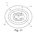
Reference is next made to FIG. 11 which is a bottom plan view of an alternative embodiment of the device of the present invention showing the interior structures of the device. From this view it can be seen that the interior structures do not necessarily directly correspond to the configuration of the exterior features, as if the device were simply a formed and shaped thin walled structure. Supine-deterrent 10′ in this view of FIG. 11 is shown to again comprise perimeter base 822 on which is positioned adhesive pad 940. Extending interior to perimeter base 822 are dome base walls 826 which generally do coordinate and correspond with the exterior appearances of these same structures.
In a similar manner, dome top wall 828 reflects a portion of its structure as viewed from the exterior of the device, albeit with fewer contours that reflect variations in the thickness of the walled structure (from dome base walls 826 up to dome top wall 828) that are provided, again so as to improve the overall rigidity of the device. In this same manner, rigidity long channel 830 is seen as a cylindrical ridge extending into the interior of the device with rigidity short channel 832 likewise forming a crossing ridge to again structure the apex of the device with greater strength.
Reference is finally made to FIGS. 7A and 7B which provide elevational side views of an individual using the device of the present invention on a sleep support surface, such as a mattress. Those skilled in the art will recognize that, in addition to the preferred embodiment shown in FIGS. 7A and 7B , other alternative embodiments could also be shown being used in a similar manner. FIG. 7A shows supine-deterrent 10 of the present invention positioned on an individual 54 sleeping on sleep support platform 50 using headrest or pillow 52. Supine-deterrent 10 is preferably placed within a target placement region 56 on the person's back. This target region is defined as that area of the person's back where skeletal support would cause contact between the supine-deterrent 10 and sleep support platform 50 in a manner that would be uncomfortable enough to alert the person, consciously or subconsciously, of the need to turn away from a back sleeping position. In other words, placement of supine-deterrent 10 too far to one side or the other, for example on the shoulders of the person, may not provide enough direct contact between the device and the mattress to give rise to the necessary level of discomfort to deter the person from remaining in the back sleeping position.
A person using a device of the present invention may position and adhere the device on their back prior to laying down on the sleep surface and falling asleep. When its adhesive surface is adhered to the body, the device serves to passively deter the individual from moving into a position that puts weight on the dome of the device, such that it can be adhered in a position to passively deter the individual from moving into an undesired position while sleeping. By adhering the device to corresponding regions of the body, this serves to prevent and minimize nocturnal repositioning and/or unintended weight loading of body parts for subjects who need to avoid as much and, in the case of those prone to snore on their backs, serves to prevent, minimize and deter snoring. Hence, as described above, by adhering the device to a subject's back, it is preferably used to deter an individual from turning onto their back during sleep and thereby deter snoring that often results from a back sleeping orientation. When the person wakes after sleep and exits the sleep surface, they may simply reach around to grasp the device (again as described above) and remove it from their back. The preferred reusable adhesive material may then be temporarily covered by a thin flexible sheet of plastic to prevent the accumulation of dirt and dust on the adhesive surface during non-use.
Although the present invention has been described in conjunction with the above preferred embodiments, those skilled in the art will recognize that certain modifications to the size, structure, and geometric configuration of the device may be made without departing from the spirit and scope of the invention. Although the various features of the device have been described with regard to their function and therefore some manner of their configuration, variations on these configurations are anticipated. While the circular shape of the device, for example, lends itself to greater ease of handling and placement, the shape may just as readily take on a ovoid configuration with little degradation in the functionality of the device. In a similar manner, greater elongation of the device along the long axis of the oval may occur as long as the entire device may still be positioned firmly and flatly against the contours of the person's back.
The size of the device is, of course, variable, but must be large enough to provide the necessary minimal discomfort to deter sleeping on the device and yet must be small enough to adhere to the back securely despite the various contours of the back that naturally occur. The diameter of the preferred embodiment of the device of the present invention is approximately five inches, the diameter at the base of reinforced dome region 14 is approximately three and one-half inches, and the height of the preferred embodiment is approximately two inches. However, those skilled in the art will recognize that such modifications as to geometries and structures are natural variations that still produce a device that achieves the desired function and purpose.
Claims (18)
1. A body positioning device for deterring a supine position in human subjects, said device comprising:
a unitary article of manufacture, said unitary article having a dome with a central axis such that said dome is radially oriented about said central axis;
a plurality of arcuate ridges located on an upper portion of an outer surface of said dome, said plurality of arcuate ridges being elevated above said outer surface of said dome, wherein said arcuate ridges provide multi-directional structural support to said dome;
a flexible annulus positioned concentrically with said central axis of said dome at a base of said dome, said annulus having a substantially planar lower surface, said substantially planar lower surface extending from the base of said dome in a plane that is perpendicular to said central axis, said substantially planar lower surface being positionable in proximity with a human subject's skin on the human subject's back, said annulus being flexible to enable conformity of said substantially planar lower surface relative to the contour of that skin; and
a contact adhesive on said substantially planar lower surface of said annulus for adhering said annulus to the skin of the human subject's back.
2. The device as defined in claim 1 , wherein said dome further comprises a dome base wall, a dome intermediate wall and a dome top wall, and wherein said dome top wall forms the apex of said dome, and said dome intermediate wall provides a generally smooth transition between said dome top wall and dome base wall.
3. The device as defined in claim 2 , wherein said plurality of arcuate ridges:
form a cross-shaped eminence centered on the apex of said dome;
extend across said dome top wall to said dome intermediate wall; and
have a cylindrical convex shape.
4. The device as defined in claim 3 , wherein said plurality of arcuate ridges do not extend onto said dome base wall.
5. The device as defined in claim 1 , wherein said dome has a shape including the general shape of an ovoid section, and wherein said dome further comprises a dome top wall of a generally ovoid shape.
6. The device as defined in claim 5 , wherein said dome top wall comprises at least two rigidity cross-channels positioned at the apex of said dome, and wherein said at least two rigidity cross-channels comprise a long cylindrical indentation positioned along the long axis of said dome crossed by a short cylindrical indentation positioned along the short axis of said dome, said rigidity cross-channels providing structural support for said dome.
7. The device as defined in claim 6 , wherein said dome further comprises a plurality of airflow apertures, said plurality of airflow apertures allowing unforced airflow between the interior and exterior areas of said dome and away from a human subject's skin.
8. The device as defined in claim 1 , wherein said article is formed from a sheet material.
9. The device as defined in claim 8 , wherein said article is preferably molded from a resilient lightweight plastic material, being die-stamped on a punch press from sheet stock of amorphous polyethylene terephthalate with a thickness of 0.0175 inches.
10. The device as defined in claim 1 , wherein said dome has a shape including a general shape of a spherical section, said dome further having a plurality of arcuate ridges positioned on an upper portion of an outer surface of said dome.
11. The device as defined in claim 10 , wherein said dome further comprises said plurality of arcuate ridges positioned orthogonally along the upper portion of the outer surface of said dome as structural reinforcement for said dome.
12. The device as defined in claim 1 , wherein the lower surface of said annulus comprises a plurality of surface recesses that depart from the generally planar shape of that lower surface such that when operatively positioned on the skin of the back, said surface recesses tend to form an opening defining airflow apertures which allow for air exchange between said annulus and the skin.
13. The device as defined in claim 12 , wherein said plurality of surface recesses are formed by a plurality of surface ridges positioned on an upper surface of said annulus, and wherein said plurality of surface ridges structurally reinforce said annulus.
14. The device as defined in claim 1 , wherein said annulus further comprises a flange positioned above said annulus at its radially outer edge circular perimeter and extending horizontally beyond the outer edge of said annulus, said flange being integral with said annulus, presenting a projection to aid in removal of said apparatus.
15. The device as defined in claim 14 , wherein said contact adhesive further comprises an adhesive protective layer, wherein said adhesive protective layer comprises a peel-off backing.
16. The device as defined in claim 1 , wherein said contact adhesive further comprises double-coated medical tape, said double-coated medical tape comprising hypoallergenic pressure-sensitive adhesives with high initial adhesion to a wide variety of substrates.
17. A body positioning device for deterring snoring posture a supine position in human subjects, said device comprising:
an article of manufacture, said article having a dome;
a plurality of arcuate ridges located on an upper portion of an outer surface of said dome, said plurality of arcuate ridges being elevated above said outer surface of said dome, wherein said arcuate ridges provide multi-directional structural support to said dome;
a flexible annulus positioned at a base of said dome, said annulus having a substantially planar lower surface positionable in proximity with a human subject's skin on the human subject's back, said annulus being flexible to enable conformity of said substantially planar lower surface relative to the contour of that skin;
a contact adhesive on the substantially planar lower surface of said annulus for adhering said annulus to the skin of the human subject's back;
said article formed from a sheet material, and said article preferably being molded from a resilient lightweight plastic material, being die-stamped on a punch press from sheet stock of amorphous polyethylene terephthalate with a thickness of 0.0175 inches;
said dome having a shape including a general shape of a spherical section, and said dome further comprising a plurality of arcuate ridges positioned orthogonally along an upper portion of an outer surface of said dome as structural reinforcement for said dome, and said dome further comprising a dome base wall, a dome intermediate wall and a dome top wall, and wherein said dome top wall forms the apex of said dome, and said dome intermediate wall provides a generally smooth transition between said dome top wall and dome base wall;
a plurality of surface recesses positioned in the lower surface of said annulus, said plurality of surface recesses departing from the generally planar shape of that lower surface such that when operatively positioned on the skin of the back, said surface recesses tend to form an opening defining airflow apertures which allow for air exchange between said annulus and the skin, and wherein said plurality of surface recesses are formed by a plurality of surface ridges positioned on an upper surface of said annulus, and wherein said plurality of surface ridges structurally reinforce said annulus, and said annulus further comprising a flange positioned above said annulus at its radially outer edge circular perimeter and extending horizontally beyond the outer edge of said annulus, said flange being integral with said annulus, presenting a projection to aid in removal of said apparatus;
said contact adhesive further comprising double-coated medical tape, said double-coated medical tape comprising hypoallergenic pressure-sensitive adhesives with high initial adhesion to a wide variety of substrates, and said contact adhesive further having an adhesive protective layer, wherein said adhesive protective layer has a peel-off backing.
18. A method for deterring a supine position of a human subject on a support platform, said method comprising the steps of:
obtaining a unitary supine-deterring device, said unitary supine-deterring device comprising:
a dome with a central axis such that said dome is radially oriented about said central axis;
a plurality of arcuate ridges located on an upper portion of an outer surface of said dome, said plurality of arcuate ridges being elevated above said outer surface of said dome, wherein said arcuate ridges provide multi-directional structural support to said dome;
a flexible annulus positioned concentrically with said central axis of said dome at a base of said dome, said annulus having a substantially planar lower surface, said substantially planar lower surface extending from the base of said dome in a plane that is perpendicular to said central axis;
a contact adhesive on said substantially planar lower surface of said annulus, said contact adhesive having an adhesive protective layer, said adhesive protective layer comprising a peel-off backing;
removing said peel-off backing from said contact adhesive;
positioning said unitary supine-deterring device within a target region on the human subject's back, said target region being an area of the human subject's back wherein skeletal support causes contact between said supine-deterring device and said support platform, wherein the contact alerts the human subject of a need to avoid said supine position;
adhering, via said contact adhesive, said unitary supine-deterring device onto the human subject's skin within said target region on the human subject's back whereby contact of said unitary supine-deterring device with the support structure deters said supine position of the human subject.
Priority Applications (9)
| Application Number | Priority Date | Filing Date | Title |
|---|---|---|---|
| US14/325,473 US10463529B2 (en) | 2012-11-05 | 2014-07-08 | Device and method for deterring back-lying snoring posture |
| CA2949451A CA2949451C (en) | 2014-05-23 | 2015-05-26 | Device & method for deterring back-lying snoring posture |
| EP15795507.1A EP3145456B1 (en) | 2014-05-23 | 2015-05-26 | Device for deterring back-lying snoring posture |
| CN201580026028.5A CN106456353A (en) | 2014-05-23 | 2015-05-26 | Device & method for deterring back-lying snoring posture |
| EP20201479.1A EP3788993A1 (en) | 2014-05-23 | 2015-05-26 | Device for deterring back-lying snoring posture |
| AU2015263906A AU2015263906B2 (en) | 2014-05-23 | 2015-05-26 | Device and method for deterring back-lying snoring posture |
| PCT/US2015/032463 WO2015179869A2 (en) | 2014-05-23 | 2015-05-26 | Device & method for deterring back-lying snoring posture |
| JP2016568827A JP6817816B2 (en) | 2014-05-23 | 2015-05-26 | A device for suppressing supine snoring posture |
| US16/673,568 US11806271B2 (en) | 2011-11-04 | 2019-11-04 | Device and method for deterring an undesirable sleeping posture |
Applications Claiming Priority (3)
| Application Number | Priority Date | Filing Date | Title |
|---|---|---|---|
| US201213669161A | 2012-11-05 | 2012-11-05 | |
| US201462002258P | 2014-05-23 | 2014-05-23 | |
| US14/325,473 US10463529B2 (en) | 2012-11-05 | 2014-07-08 | Device and method for deterring back-lying snoring posture |
Related Parent Applications (1)
| Application Number | Title | Priority Date | Filing Date |
|---|---|---|---|
| US201213669161A Continuation-In-Part | 2011-11-04 | 2012-11-05 |
Related Child Applications (1)
| Application Number | Title | Priority Date | Filing Date |
|---|---|---|---|
| US16/673,568 Continuation US11806271B2 (en) | 2011-11-04 | 2019-11-04 | Device and method for deterring an undesirable sleeping posture |
Publications (2)
| Publication Number | Publication Date |
|---|---|
| US20150238346A1 US20150238346A1 (en) | 2015-08-27 |
| US10463529B2 true US10463529B2 (en) | 2019-11-05 |
Family
ID=53881143
Family Applications (2)
| Application Number | Title | Priority Date | Filing Date |
|---|---|---|---|
| US14/325,473 Active 2036-04-02 US10463529B2 (en) | 2011-11-04 | 2014-07-08 | Device and method for deterring back-lying snoring posture |
| US16/673,568 Active 2033-06-10 US11806271B2 (en) | 2011-11-04 | 2019-11-04 | Device and method for deterring an undesirable sleeping posture |
Family Applications After (1)
| Application Number | Title | Priority Date | Filing Date |
|---|---|---|---|
| US16/673,568 Active 2033-06-10 US11806271B2 (en) | 2011-11-04 | 2019-11-04 | Device and method for deterring an undesirable sleeping posture |
Country Status (7)
| Country | Link |
|---|---|
| US (2) | US10463529B2 (en) |
| EP (2) | EP3788993A1 (en) |
| JP (1) | JP6817816B2 (en) |
| CN (1) | CN106456353A (en) |
| AU (1) | AU2015263906B2 (en) |
| CA (1) | CA2949451C (en) |
| WO (1) | WO2015179869A2 (en) |
Families Citing this family (4)
| Publication number | Priority date | Publication date | Assignee | Title |
|---|---|---|---|---|
| US10335322B2 (en) | 2013-08-26 | 2019-07-02 | Lightside Md, Llc | Adhesive support devices and methods of making and using them |
| US10786652B2 (en) | 2013-10-18 | 2020-09-29 | Lightside Md, Llc | Support devices and methods of making and using them |
| CN110974238B (en) * | 2019-11-14 | 2020-11-03 | 北京理工大学 | Human body sleep pose identification and pushing point determination method and device for snore stopping mattress |
| WO2022099110A1 (en) * | 2020-11-06 | 2022-05-12 | Marsco Medical, LLC | Port protector and cover system and method of use |
Citations (56)
| Publication number | Priority date | Publication date | Assignee | Title |
|---|---|---|---|---|
| US695270A (en) | 1901-12-05 | 1902-03-11 | George M Beringer | Vaccine-shield. |
| US876491A (en) | 1907-08-05 | 1908-01-14 | Carl F Rohwer | Antisnoring device. |
| US898379A (en) | 1908-01-11 | 1908-09-08 | Louis F Liebhardt | Antisnoring device. |
| US1194200A (en) | 1916-08-08 | Ckockett lowdeb | ||
| US2304235A (en) | 1941-06-05 | 1942-12-08 | Edmund R Boots | Sleeping garment |
| US2367690A (en) * | 1943-07-31 | 1945-01-23 | Edgar H Purdy | Wound protector |
| US2952856A (en) | 1956-08-15 | 1960-09-20 | Clarence B Ruff | Adjustable pillow support |
| US3485241A (en) | 1967-11-09 | 1969-12-23 | Robert F L Polley | Infant sleeping garment with posterior posture pad |
| DE2249975A1 (en) | 1972-10-12 | 1974-04-18 | Georg Dipl Ing Vujovic | Air bag for pyjamas/nightshirt - attached to back to prevent sleeping on back and inhibit snoring |
| US3924282A (en) | 1974-06-21 | 1975-12-09 | Helen Inez Bond | Therapeutic prop-like support for hemiside reclining persons |
| US4118813A (en) | 1976-11-10 | 1978-10-10 | Armstrong Nolen L | Sleep training pillow for the prevention of snoring |
| US4349925A (en) | 1980-03-13 | 1982-09-21 | James K. Macomber | Physiological pillow |
| US4517971A (en) * | 1982-11-22 | 1985-05-21 | Sorbonne Robert L | Guard for venipuncture site and catheter retainer |
| US4744117A (en) | 1984-09-17 | 1988-05-17 | Helen Inez Bond | Prop-like positioning device for hemiside reclining persons |
| US5036865A (en) | 1990-06-04 | 1991-08-06 | Keaton Powell J | Sleepwear |
| US5040546A (en) | 1989-12-21 | 1991-08-20 | Lunar Corporation | Patient positioning device and method |
| US5165130A (en) | 1992-01-24 | 1992-11-24 | Wendling Helen L | Multipositional infant support system |
| US5357981A (en) | 1993-07-07 | 1994-10-25 | Zohar Eilam | Apparatus and method for the prevention of snoring |
| USD352377S (en) | 1993-03-17 | 1994-11-15 | Yury Furman | Vest for discouraging supine posture |
| US5383475A (en) | 1994-03-14 | 1995-01-24 | Austin; Ronald J. | Snore deterring belt |
| USD362331S (en) | 1994-06-02 | 1995-09-19 | Berger Ii Thomas | Nightshirt |
| US5618899A (en) * | 1990-05-02 | 1997-04-08 | Minnesota Mining & Mfg | Crosslinked pressure-sensitive adhesives tolerant of alcohol-based excipients used in transdermal delivery devices and method of preparing same |
| US5752524A (en) | 1997-06-12 | 1998-05-19 | Corcoran; Timothy C. | Device for preventing or reducing snoring |
| USD398139S (en) | 1996-05-06 | 1998-09-15 | Galgon John P | Anti-snoring sleep wear |
| US5893365A (en) | 1997-07-28 | 1999-04-13 | Anderson; Clarence D. | Appliance for preventing snoring and obstructive sleep apnea |
| US6289893B1 (en) | 1999-08-06 | 2001-09-18 | Harold O. Levitt | Snore reducer jacket |
| US6357444B1 (en) | 1998-02-18 | 2002-03-19 | Jonathan A. Parker | Motion limiting device |
| US20030069529A1 (en) | 1994-11-21 | 2003-04-10 | Augustine Scott D. | Flexible non-contact wound treatment device |
| US6698432B2 (en) | 2000-01-27 | 2004-03-02 | Silent Sleep Ab | Movable device against snoring |
| US6926008B1 (en) * | 2004-04-01 | 2005-08-09 | Harold O. Levitt | Snore relief belt |
| US20050178392A1 (en) | 2004-02-16 | 2005-08-18 | Tinsley Thomas A. | Device to reduce snoring, drooling, and talking while sleeping |
| US7055526B2 (en) | 2000-08-09 | 2006-06-06 | Mohamed Ali Bakarat | Anti-snoring device comprising a skin compatible adhesive |
| US7134435B2 (en) | 2003-10-22 | 2006-11-14 | Mayo Foundation For Medical Education And Research | Sleeping apparatus and related methods |
| US20070129664A1 (en) * | 2003-11-18 | 2007-06-07 | Yasushi Fuchita | Electrode chip for biological application and its using method |
| US20070256695A1 (en) * | 2006-05-03 | 2007-11-08 | Joseph Crocetti | Devices for treating obstructive sleep apnea and/or snoring |
| US20070283962A1 (en) * | 2006-06-07 | 2007-12-13 | Ventus Medical, Inc. | Layered nasal devices |
| US20080163428A1 (en) | 2006-12-21 | 2008-07-10 | Back2Sleep, Llc. | Head and upper neck support device |
| US20080256710A1 (en) | 2007-04-20 | 2008-10-23 | Ying-Chuan Ho | Multifunctional pillow |
| US7469434B2 (en) | 2005-07-15 | 2008-12-30 | Drucker Linda W | Anti-snore sleep positioning method and devices |
| US20090038077A1 (en) | 2007-08-06 | 2009-02-12 | Jin Kyu Han | Sleeping posture supporting apparatus |
| CN201257046Y (en) | 2008-09-18 | 2009-06-17 | 高思山 | Lateral lying device capable of smoothing air-way |
| US20090229618A1 (en) | 2008-03-13 | 2009-09-17 | Serenity And Prosperity Enterprises, Llc | Sleep positioning apparatus |
| US20090318842A1 (en) | 2006-07-05 | 2009-12-24 | Nicolas Kairinos | Orthopaedic pin isolator |
| EP2161011A1 (en) | 2008-09-03 | 2010-03-10 | Gert Pistor | Wound protection |
| CN201510386U (en) | 2009-10-18 | 2010-06-23 | 姜文静 | Vest for adjusting sleeping postures |
| US20100199436A1 (en) | 2008-01-25 | 2010-08-12 | John Schultz | Sleep system |
| CN201571511U (en) | 2009-12-21 | 2010-09-08 | 杨丽莎 | Snoring prevention garment |
| US20100319131A1 (en) | 2009-06-23 | 2010-12-23 | North Vaughn W | Suspended Back Pillow for Sustaining a Side Sleeping Position |
| US20110179573A1 (en) | 2006-07-28 | 2011-07-28 | North Vaughn W | Suspended Back Pillow For Sustaining A Side Sleeping Position |
| US7988673B2 (en) * | 2005-07-14 | 2011-08-02 | Venetec International, Inc. | Protective dressing and methods of use thereof |
| US8118030B1 (en) | 2007-10-23 | 2012-02-21 | Bugeja Edward L | Head position control device |
| US20120167895A1 (en) | 2011-01-03 | 2012-07-05 | Sanjiv Tewari | Therapeutic sleep device for discouraging sleeping in a supine position |
| CN202603673U (en) | 2012-04-10 | 2012-12-19 | 梁文涛 | A pair of pyjamas |
| US20130102945A1 (en) | 2010-07-12 | 2013-04-25 | Martin Long Medical Products, Llc | Protective wound shield |
| US20140060548A1 (en) * | 2011-05-17 | 2014-03-06 | Todd Check | Protective Bandage Device |
| FR3004922A1 (en) | 2013-04-27 | 2014-10-31 | Simp Soc Ind De Materiel Paramedical | ANTI-ROUNDER DEVICE |
Family Cites Families (4)
| Publication number | Priority date | Publication date | Assignee | Title |
|---|---|---|---|---|
| US4212296A (en) * | 1978-04-20 | 1980-07-15 | The Kendall Company | Bandage with protective member |
| JPH01122723U (en) * | 1988-02-12 | 1989-08-21 | ||
| US5144958A (en) * | 1989-06-28 | 1992-09-08 | Mobil Oil Corporation | Apparatus for conducting mammalian dermatological studies |
| JP3116982U (en) * | 2004-07-07 | 2006-01-05 | 昭一 新田 | Sleep apnea measures |
-
2014
- 2014-07-08 US US14/325,473 patent/US10463529B2/en active Active
-
2015
- 2015-05-26 CN CN201580026028.5A patent/CN106456353A/en active Pending
- 2015-05-26 CA CA2949451A patent/CA2949451C/en active Active
- 2015-05-26 JP JP2016568827A patent/JP6817816B2/en active Active
- 2015-05-26 EP EP20201479.1A patent/EP3788993A1/en active Pending
- 2015-05-26 WO PCT/US2015/032463 patent/WO2015179869A2/en active Application Filing
- 2015-05-26 AU AU2015263906A patent/AU2015263906B2/en active Active
- 2015-05-26 EP EP15795507.1A patent/EP3145456B1/en active Active
-
2019
- 2019-11-04 US US16/673,568 patent/US11806271B2/en active Active
Patent Citations (57)
| Publication number | Priority date | Publication date | Assignee | Title |
|---|---|---|---|---|
| US1194200A (en) | 1916-08-08 | Ckockett lowdeb | ||
| US695270A (en) | 1901-12-05 | 1902-03-11 | George M Beringer | Vaccine-shield. |
| US876491A (en) | 1907-08-05 | 1908-01-14 | Carl F Rohwer | Antisnoring device. |
| US898379A (en) | 1908-01-11 | 1908-09-08 | Louis F Liebhardt | Antisnoring device. |
| US2304235A (en) | 1941-06-05 | 1942-12-08 | Edmund R Boots | Sleeping garment |
| US2367690A (en) * | 1943-07-31 | 1945-01-23 | Edgar H Purdy | Wound protector |
| US2952856A (en) | 1956-08-15 | 1960-09-20 | Clarence B Ruff | Adjustable pillow support |
| US3485241A (en) | 1967-11-09 | 1969-12-23 | Robert F L Polley | Infant sleeping garment with posterior posture pad |
| DE2249975A1 (en) | 1972-10-12 | 1974-04-18 | Georg Dipl Ing Vujovic | Air bag for pyjamas/nightshirt - attached to back to prevent sleeping on back and inhibit snoring |
| US3924282A (en) | 1974-06-21 | 1975-12-09 | Helen Inez Bond | Therapeutic prop-like support for hemiside reclining persons |
| US4118813A (en) | 1976-11-10 | 1978-10-10 | Armstrong Nolen L | Sleep training pillow for the prevention of snoring |
| US4349925A (en) | 1980-03-13 | 1982-09-21 | James K. Macomber | Physiological pillow |
| US4517971A (en) * | 1982-11-22 | 1985-05-21 | Sorbonne Robert L | Guard for venipuncture site and catheter retainer |
| US4744117A (en) | 1984-09-17 | 1988-05-17 | Helen Inez Bond | Prop-like positioning device for hemiside reclining persons |
| US5040546A (en) | 1989-12-21 | 1991-08-20 | Lunar Corporation | Patient positioning device and method |
| US5618899A (en) * | 1990-05-02 | 1997-04-08 | Minnesota Mining & Mfg | Crosslinked pressure-sensitive adhesives tolerant of alcohol-based excipients used in transdermal delivery devices and method of preparing same |
| US5036865A (en) | 1990-06-04 | 1991-08-06 | Keaton Powell J | Sleepwear |
| US5165130A (en) | 1992-01-24 | 1992-11-24 | Wendling Helen L | Multipositional infant support system |
| USD352377S (en) | 1993-03-17 | 1994-11-15 | Yury Furman | Vest for discouraging supine posture |
| US5357981A (en) | 1993-07-07 | 1994-10-25 | Zohar Eilam | Apparatus and method for the prevention of snoring |
| US5383475A (en) | 1994-03-14 | 1995-01-24 | Austin; Ronald J. | Snore deterring belt |
| USD362331S (en) | 1994-06-02 | 1995-09-19 | Berger Ii Thomas | Nightshirt |
| US20030069529A1 (en) | 1994-11-21 | 2003-04-10 | Augustine Scott D. | Flexible non-contact wound treatment device |
| USD398139S (en) | 1996-05-06 | 1998-09-15 | Galgon John P | Anti-snoring sleep wear |
| US5752524A (en) | 1997-06-12 | 1998-05-19 | Corcoran; Timothy C. | Device for preventing or reducing snoring |
| US5893365A (en) | 1997-07-28 | 1999-04-13 | Anderson; Clarence D. | Appliance for preventing snoring and obstructive sleep apnea |
| US6357444B1 (en) | 1998-02-18 | 2002-03-19 | Jonathan A. Parker | Motion limiting device |
| US6289893B1 (en) | 1999-08-06 | 2001-09-18 | Harold O. Levitt | Snore reducer jacket |
| US6698432B2 (en) | 2000-01-27 | 2004-03-02 | Silent Sleep Ab | Movable device against snoring |
| US7055526B2 (en) | 2000-08-09 | 2006-06-06 | Mohamed Ali Bakarat | Anti-snoring device comprising a skin compatible adhesive |
| US7134435B2 (en) | 2003-10-22 | 2006-11-14 | Mayo Foundation For Medical Education And Research | Sleeping apparatus and related methods |
| US20070129664A1 (en) * | 2003-11-18 | 2007-06-07 | Yasushi Fuchita | Electrode chip for biological application and its using method |
| US20050178392A1 (en) | 2004-02-16 | 2005-08-18 | Tinsley Thomas A. | Device to reduce snoring, drooling, and talking while sleeping |
| US6926008B1 (en) * | 2004-04-01 | 2005-08-09 | Harold O. Levitt | Snore relief belt |
| US7988673B2 (en) * | 2005-07-14 | 2011-08-02 | Venetec International, Inc. | Protective dressing and methods of use thereof |
| US7469434B2 (en) | 2005-07-15 | 2008-12-30 | Drucker Linda W | Anti-snore sleep positioning method and devices |
| US20070256695A1 (en) * | 2006-05-03 | 2007-11-08 | Joseph Crocetti | Devices for treating obstructive sleep apnea and/or snoring |
| US20070283962A1 (en) * | 2006-06-07 | 2007-12-13 | Ventus Medical, Inc. | Layered nasal devices |
| US20090318842A1 (en) | 2006-07-05 | 2009-12-24 | Nicolas Kairinos | Orthopaedic pin isolator |
| US20110179573A1 (en) | 2006-07-28 | 2011-07-28 | North Vaughn W | Suspended Back Pillow For Sustaining A Side Sleeping Position |
| US20080163428A1 (en) | 2006-12-21 | 2008-07-10 | Back2Sleep, Llc. | Head and upper neck support device |
| US20080256710A1 (en) | 2007-04-20 | 2008-10-23 | Ying-Chuan Ho | Multifunctional pillow |
| US20090038077A1 (en) | 2007-08-06 | 2009-02-12 | Jin Kyu Han | Sleeping posture supporting apparatus |
| US8118030B1 (en) | 2007-10-23 | 2012-02-21 | Bugeja Edward L | Head position control device |
| US20100199436A1 (en) | 2008-01-25 | 2010-08-12 | John Schultz | Sleep system |
| US20090229618A1 (en) | 2008-03-13 | 2009-09-17 | Serenity And Prosperity Enterprises, Llc | Sleep positioning apparatus |
| EP2161011A1 (en) | 2008-09-03 | 2010-03-10 | Gert Pistor | Wound protection |
| CN201257046Y (en) | 2008-09-18 | 2009-06-17 | 高思山 | Lateral lying device capable of smoothing air-way |
| US20100319131A1 (en) | 2009-06-23 | 2010-12-23 | North Vaughn W | Suspended Back Pillow for Sustaining a Side Sleeping Position |
| US8429775B2 (en) | 2009-06-23 | 2013-04-30 | Vaughn W. North | Suspended back pillow for sustaining a side sleeping position |
| CN201510386U (en) | 2009-10-18 | 2010-06-23 | 姜文静 | Vest for adjusting sleeping postures |
| CN201571511U (en) | 2009-12-21 | 2010-09-08 | 杨丽莎 | Snoring prevention garment |
| US20130102945A1 (en) | 2010-07-12 | 2013-04-25 | Martin Long Medical Products, Llc | Protective wound shield |
| US20120167895A1 (en) | 2011-01-03 | 2012-07-05 | Sanjiv Tewari | Therapeutic sleep device for discouraging sleeping in a supine position |
| US20140060548A1 (en) * | 2011-05-17 | 2014-03-06 | Todd Check | Protective Bandage Device |
| CN202603673U (en) | 2012-04-10 | 2012-12-19 | 梁文涛 | A pair of pyjamas |
| FR3004922A1 (en) | 2013-04-27 | 2014-10-31 | Simp Soc Ind De Materiel Paramedical | ANTI-ROUNDER DEVICE |
Also Published As
| Publication number | Publication date |
|---|---|
| EP3145456A4 (en) | 2018-05-02 |
| AU2015263906B2 (en) | 2019-10-03 |
| WO2015179869A2 (en) | 2015-11-26 |
| AU2015263906A1 (en) | 2016-11-24 |
| JP2017516545A (en) | 2017-06-22 |
| JP6817816B2 (en) | 2021-01-20 |
| CA2949451C (en) | 2023-08-22 |
| EP3788993A1 (en) | 2021-03-10 |
| CA2949451A1 (en) | 2015-11-26 |
| US20150238346A1 (en) | 2015-08-27 |
| CN106456353A (en) | 2017-02-22 |
| EP3145456A2 (en) | 2017-03-29 |
| EP3145456B1 (en) | 2020-10-14 |
| US20200129323A1 (en) | 2020-04-30 |
| US11806271B2 (en) | 2023-11-07 |
| WO2015179869A3 (en) | 2016-04-07 |
Similar Documents
| Publication | Publication Date | Title |
|---|---|---|
| US11806271B2 (en) | Device and method for deterring an undesirable sleeping posture | |
| US20200155396A1 (en) | Method, system, and apparatus for facilitating positioning a person in supine sniff position and providing scapular relief | |
| US7424929B1 (en) | Cover for a bell or a diaphragm of a stethoscope | |
| US8272385B2 (en) | Method for treating obstructive sleep apnea and/or snoring | |
| US8006335B1 (en) | Post retinal operation pillow | |
| US20210100690A1 (en) | Wound covering apparatus | |
| US5755232A (en) | Universal anatomical support device and method of using same | |
| US20130046219A1 (en) | Neonatal cranial support bonnet | |
| US20120180221A1 (en) | Infant Support Device | |
| US20140096777A1 (en) | Sleeping Device to Prevent Snoring | |
| JP2003061791A (en) | Bedding | |
| CN209711643U (en) | A kind of head protector worn suitable for head injury person | |
| CN206275771U (en) | A kind of bandage of protection wound site | |
| JP3136159U (en) | Male urine collector | |
| US9226596B2 (en) | Infant support device | |
| JP2003190200A (en) | Snore preventive seal | |
| JPH0630826Y2 (en) | Adhesive tape | |
| CN202113210U (en) | Disposable multilayer medical neck support lining | |
| KR20220126150A (en) | (nasal dilators) | |
| JP3118069U (en) | Skirt cover for preventing pervert | |
| KR20170097508A (en) | Nasal respiration induction mask | |
| JPWO2003068127A1 (en) | Urine collection device for men and urine collection method using the same |
Legal Events
| Date | Code | Title | Description |
|---|---|---|---|
| STCV | Information on status: appeal procedure |
Free format text: APPEAL BRIEF (OR SUPPLEMENTAL BRIEF) ENTERED AND FORWARDED TO EXAMINER |
|
| STPP | Information on status: patent application and granting procedure in general |
Free format text: NOTICE OF ALLOWANCE MAILED -- APPLICATION RECEIVED IN OFFICE OF PUBLICATIONS |
|
| STPP | Information on status: patent application and granting procedure in general |
Free format text: PUBLICATIONS -- ISSUE FEE PAYMENT VERIFIED |
|
| STCF | Information on status: patent grant |
Free format text: PATENTED CASE |
|
| MAFP | Maintenance fee payment |
Free format text: PAYMENT OF MAINTENANCE FEE, 4TH YR, SMALL ENTITY (ORIGINAL EVENT CODE: M2551); ENTITY STATUS OF PATENT OWNER: SMALL ENTITY Year of fee payment: 4 |