US10453473B2 - Noise-reduction system for UAVs - Google Patents
Noise-reduction system for UAVs Download PDFInfo
- Publication number
- US10453473B2 US10453473B2 US15/849,841 US201715849841A US10453473B2 US 10453473 B2 US10453473 B2 US 10453473B2 US 201715849841 A US201715849841 A US 201715849841A US 10453473 B2 US10453473 B2 US 10453473B2
- Authority
- US
- United States
- Prior art keywords
- acoustic
- waveform
- uav
- noise
- flight
- Prior art date
- Legal status (The legal status is an assumption and is not a legal conclusion. Google has not performed a legal analysis and makes no representation as to the accuracy of the status listed.)
- Active
Links
- 238000000034 method Methods 0.000 claims abstract description 24
- 230000005534 acoustic noise Effects 0.000 claims description 44
- RZVHIXYEVGDQDX-UHFFFAOYSA-N 9,10-anthraquinone Chemical compound C1=CC=C2C(=O)C3=CC=CC=C3C(=O)C2=C1 RZVHIXYEVGDQDX-UHFFFAOYSA-N 0.000 claims description 13
- 238000012545 processing Methods 0.000 claims description 13
- 230000007613 environmental effect Effects 0.000 claims description 10
- 239000013598 vector Substances 0.000 claims description 9
- 230000009467 reduction Effects 0.000 claims description 7
- 230000001066 destructive effect Effects 0.000 claims description 4
- 230000001133 acceleration Effects 0.000 claims description 2
- 238000003860 storage Methods 0.000 claims description 2
- 230000003044 adaptive effect Effects 0.000 abstract description 3
- 230000002829 reductive effect Effects 0.000 abstract description 3
- 230000006870 function Effects 0.000 description 19
- 230000001629 suppression Effects 0.000 description 13
- 238000010586 diagram Methods 0.000 description 4
- 238000004458 analytical method Methods 0.000 description 3
- 230000003466 anti-cipated effect Effects 0.000 description 3
- 239000000463 material Substances 0.000 description 3
- 238000001228 spectrum Methods 0.000 description 3
- 239000011358 absorbing material Substances 0.000 description 2
- 230000002411 adverse Effects 0.000 description 2
- 238000003491 array Methods 0.000 description 2
- 238000004891 communication Methods 0.000 description 2
- 230000005484 gravity Effects 0.000 description 2
- 230000000670 limiting effect Effects 0.000 description 2
- 230000008569 process Effects 0.000 description 2
- 238000013139 quantization Methods 0.000 description 2
- 230000004044 response Effects 0.000 description 2
- 230000005236 sound signal Effects 0.000 description 2
- 238000012546 transfer Methods 0.000 description 2
- 230000001052 transient effect Effects 0.000 description 2
- 238000010521 absorption reaction Methods 0.000 description 1
- 230000009471 action Effects 0.000 description 1
- 230000001413 cellular effect Effects 0.000 description 1
- 230000001143 conditioned effect Effects 0.000 description 1
- 238000012937 correction Methods 0.000 description 1
- 238000013480 data collection Methods 0.000 description 1
- 230000001419 dependent effect Effects 0.000 description 1
- 238000005265 energy consumption Methods 0.000 description 1
- 239000006260 foam Substances 0.000 description 1
- 238000003780 insertion Methods 0.000 description 1
- 230000037431 insertion Effects 0.000 description 1
- 238000004519 manufacturing process Methods 0.000 description 1
- 230000007246 mechanism Effects 0.000 description 1
- 230000000116 mitigating effect Effects 0.000 description 1
- 230000010355 oscillation Effects 0.000 description 1
- 238000001556 precipitation Methods 0.000 description 1
- 230000007480 spreading Effects 0.000 description 1
- 238000003892 spreading Methods 0.000 description 1
- 230000003068 static effect Effects 0.000 description 1
- 230000036962 time dependent Effects 0.000 description 1
- 238000005303 weighing Methods 0.000 description 1
Images


Classifications
-
- G—PHYSICS
- G10—MUSICAL INSTRUMENTS; ACOUSTICS
- G10L—SPEECH ANALYSIS OR SYNTHESIS; SPEECH RECOGNITION; SPEECH OR VOICE PROCESSING; SPEECH OR AUDIO CODING OR DECODING
- G10L21/00—Processing of the speech or voice signal to produce another audible or non-audible signal, e.g. visual or tactile, in order to modify its quality or its intelligibility
- G10L21/02—Speech enhancement, e.g. noise reduction or echo cancellation
- G10L21/0208—Noise filtering
- G10L21/0216—Noise filtering characterised by the method used for estimating noise
- G10L21/0232—Processing in the frequency domain
-
- B—PERFORMING OPERATIONS; TRANSPORTING
- B64—AIRCRAFT; AVIATION; COSMONAUTICS
- B64C—AEROPLANES; HELICOPTERS
- B64C39/00—Aircraft not otherwise provided for
- B64C39/02—Aircraft not otherwise provided for characterised by special use
- B64C39/024—Aircraft not otherwise provided for characterised by special use of the remote controlled vehicle type, i.e. RPV
-
- B—PERFORMING OPERATIONS; TRANSPORTING
- B64—AIRCRAFT; AVIATION; COSMONAUTICS
- B64U—UNMANNED AERIAL VEHICLES [UAV]; EQUIPMENT THEREFOR
- B64U20/00—Constructional aspects of UAVs
- B64U20/20—Constructional aspects of UAVs for noise reduction
-
- G—PHYSICS
- G10—MUSICAL INSTRUMENTS; ACOUSTICS
- G10K—SOUND-PRODUCING DEVICES; METHODS OR DEVICES FOR PROTECTING AGAINST, OR FOR DAMPING, NOISE OR OTHER ACOUSTIC WAVES IN GENERAL; ACOUSTICS NOT OTHERWISE PROVIDED FOR
- G10K11/00—Methods or devices for transmitting, conducting or directing sound in general; Methods or devices for protecting against, or for damping, noise or other acoustic waves in general
- G10K11/002—Devices for damping, suppressing, obstructing or conducting sound in acoustic devices
-
- G—PHYSICS
- G10—MUSICAL INSTRUMENTS; ACOUSTICS
- G10L—SPEECH ANALYSIS OR SYNTHESIS; SPEECH RECOGNITION; SPEECH OR VOICE PROCESSING; SPEECH OR AUDIO CODING OR DECODING
- G10L21/00—Processing of the speech or voice signal to produce another audible or non-audible signal, e.g. visual or tactile, in order to modify its quality or its intelligibility
- G10L21/02—Speech enhancement, e.g. noise reduction or echo cancellation
- G10L21/0208—Noise filtering
-
- G—PHYSICS
- G10—MUSICAL INSTRUMENTS; ACOUSTICS
- G10L—SPEECH ANALYSIS OR SYNTHESIS; SPEECH RECOGNITION; SPEECH OR VOICE PROCESSING; SPEECH OR AUDIO CODING OR DECODING
- G10L25/00—Speech or voice analysis techniques not restricted to a single one of groups G10L15/00 - G10L21/00
- G10L25/48—Speech or voice analysis techniques not restricted to a single one of groups G10L15/00 - G10L21/00 specially adapted for particular use
- G10L25/51—Speech or voice analysis techniques not restricted to a single one of groups G10L15/00 - G10L21/00 specially adapted for particular use for comparison or discrimination
-
- H—ELECTRICITY
- H04—ELECTRIC COMMUNICATION TECHNIQUE
- H04R—LOUDSPEAKERS, MICROPHONES, GRAMOPHONE PICK-UPS OR LIKE ACOUSTIC ELECTROMECHANICAL TRANSDUCERS; DEAF-AID SETS; PUBLIC ADDRESS SYSTEMS
- H04R1/00—Details of transducers, loudspeakers or microphones
- H04R1/02—Casings; Cabinets ; Supports therefor; Mountings therein
- H04R1/028—Casings; Cabinets ; Supports therefor; Mountings therein associated with devices performing functions other than acoustics, e.g. electric candles
-
- H—ELECTRICITY
- H04—ELECTRIC COMMUNICATION TECHNIQUE
- H04R—LOUDSPEAKERS, MICROPHONES, GRAMOPHONE PICK-UPS OR LIKE ACOUSTIC ELECTROMECHANICAL TRANSDUCERS; DEAF-AID SETS; PUBLIC ADDRESS SYSTEMS
- H04R1/00—Details of transducers, loudspeakers or microphones
- H04R1/08—Mouthpieces; Microphones; Attachments therefor
-
- H—ELECTRICITY
- H04—ELECTRIC COMMUNICATION TECHNIQUE
- H04R—LOUDSPEAKERS, MICROPHONES, GRAMOPHONE PICK-UPS OR LIKE ACOUSTIC ELECTROMECHANICAL TRANSDUCERS; DEAF-AID SETS; PUBLIC ADDRESS SYSTEMS
- H04R3/00—Circuits for transducers, loudspeakers or microphones
-
- B64C2201/027—
-
- B64C2201/108—
-
- B64C2201/141—
-
- B64C2201/146—
-
- B—PERFORMING OPERATIONS; TRANSPORTING
- B64—AIRCRAFT; AVIATION; COSMONAUTICS
- B64U—UNMANNED AERIAL VEHICLES [UAV]; EQUIPMENT THEREFOR
- B64U10/00—Type of UAV
- B64U10/10—Rotorcrafts
- B64U10/13—Flying platforms
-
- B—PERFORMING OPERATIONS; TRANSPORTING
- B64—AIRCRAFT; AVIATION; COSMONAUTICS
- B64U—UNMANNED AERIAL VEHICLES [UAV]; EQUIPMENT THEREFOR
- B64U10/00—Type of UAV
- B64U10/10—Rotorcrafts
- B64U10/13—Flying platforms
- B64U10/14—Flying platforms with four distinct rotor axes, e.g. quadcopters
-
- B—PERFORMING OPERATIONS; TRANSPORTING
- B64—AIRCRAFT; AVIATION; COSMONAUTICS
- B64U—UNMANNED AERIAL VEHICLES [UAV]; EQUIPMENT THEREFOR
- B64U2101/00—UAVs specially adapted for particular uses or applications
- B64U2101/60—UAVs specially adapted for particular uses or applications for transporting passengers; for transporting goods other than weapons
- B64U2101/67—UAVs specially adapted for particular uses or applications for transporting passengers; for transporting goods other than weapons the UAVs comprising tethers for lowering the goods
-
- B—PERFORMING OPERATIONS; TRANSPORTING
- B64—AIRCRAFT; AVIATION; COSMONAUTICS
- B64U—UNMANNED AERIAL VEHICLES [UAV]; EQUIPMENT THEREFOR
- B64U2201/00—UAVs characterised by their flight controls
- B64U2201/10—UAVs characterised by their flight controls autonomous, i.e. by navigating independently from ground or air stations, e.g. by using inertial navigation systems [INS]
-
- B—PERFORMING OPERATIONS; TRANSPORTING
- B64—AIRCRAFT; AVIATION; COSMONAUTICS
- B64U—UNMANNED AERIAL VEHICLES [UAV]; EQUIPMENT THEREFOR
- B64U2201/00—UAVs characterised by their flight controls
- B64U2201/20—Remote controls
-
- B—PERFORMING OPERATIONS; TRANSPORTING
- B64—AIRCRAFT; AVIATION; COSMONAUTICS
- B64U—UNMANNED AERIAL VEHICLES [UAV]; EQUIPMENT THEREFOR
- B64U30/00—Means for producing lift; Empennages; Arrangements thereof
- B64U30/20—Rotors; Rotor supports
-
- B—PERFORMING OPERATIONS; TRANSPORTING
- B64—AIRCRAFT; AVIATION; COSMONAUTICS
- B64U—UNMANNED AERIAL VEHICLES [UAV]; EQUIPMENT THEREFOR
- B64U50/00—Propulsion; Power supply
- B64U50/10—Propulsion
- B64U50/19—Propulsion using electrically powered motors
-
- G—PHYSICS
- G10—MUSICAL INSTRUMENTS; ACOUSTICS
- G10K—SOUND-PRODUCING DEVICES; METHODS OR DEVICES FOR PROTECTING AGAINST, OR FOR DAMPING, NOISE OR OTHER ACOUSTIC WAVES IN GENERAL; ACOUSTICS NOT OTHERWISE PROVIDED FOR
- G10K2200/00—Details of methods or devices for transmitting, conducting or directing sound in general
- G10K2200/10—Beamforming, e.g. time reversal, phase conjugation or similar
-
- G—PHYSICS
- G10—MUSICAL INSTRUMENTS; ACOUSTICS
- G10L—SPEECH ANALYSIS OR SYNTHESIS; SPEECH RECOGNITION; SPEECH OR VOICE PROCESSING; SPEECH OR AUDIO CODING OR DECODING
- G10L21/00—Processing of the speech or voice signal to produce another audible or non-audible signal, e.g. visual or tactile, in order to modify its quality or its intelligibility
- G10L21/02—Speech enhancement, e.g. noise reduction or echo cancellation
- G10L21/0208—Noise filtering
- G10L2021/02085—Periodic noise
-
- H—ELECTRICITY
- H04—ELECTRIC COMMUNICATION TECHNIQUE
- H04R—LOUDSPEAKERS, MICROPHONES, GRAMOPHONE PICK-UPS OR LIKE ACOUSTIC ELECTROMECHANICAL TRANSDUCERS; DEAF-AID SETS; PUBLIC ADDRESS SYSTEMS
- H04R2410/00—Microphones
- H04R2410/05—Noise reduction with a separate noise microphone
-
- H—ELECTRICITY
- H04—ELECTRIC COMMUNICATION TECHNIQUE
- H04R—LOUDSPEAKERS, MICROPHONES, GRAMOPHONE PICK-UPS OR LIKE ACOUSTIC ELECTROMECHANICAL TRANSDUCERS; DEAF-AID SETS; PUBLIC ADDRESS SYSTEMS
- H04R2499/00—Aspects covered by H04R or H04S not otherwise provided for in their subgroups
- H04R2499/10—General applications
- H04R2499/13—Acoustic transducers and sound field adaptation in vehicles
Definitions
- the present application is related to acoustic noise suppression, and in particular, to mitigating undesirable acoustic noise in acoustic data collected by an unmanned aerial vehicle (UAV).
- UAV unmanned aerial vehicle
- UAVs can be used for a variety of tasks, including surveillance, reconnaissance, photography, videography, emergency responding, delivery of articles, and other tasks.
- Various sensors may be placed on UAVs for remote data collection.
- the data may be stored in UAV memory or streamed to a user operating UAV in real time.
- UAVs for collecting audio data
- Prior art solutions to reduce noise from these components are complex, leading to impractical costs, size, and, or weight.
- Prior art generally relates to active noise cancellation, such as the use of phased arrays of a plurality of microphone sources to measure and subtract ambient noise in real time.
- U.S. Patent Application 2016/0063987 A1 “UNMANNED AERIAL VEHICLE (UAV) FOR COLLECTING AUDIO DATA” describes a noise-cancellation system using at least two microphones and a relatively complex low-latency microprocessor to perform the active noise cancellation function.
- the present disclosure relates to a method and system for reducing background noise in signals captured by UAV-mounted acoustic sensors.
- the disclosed embodiments may enable a reduction in the cost, weight, size, and complexity of on-board sensors and computing systems while achieving generally acceptable noise reduction.
- one aspect of the present disclosure encompasses the use of a relatively small set of acoustic data sensors.
- One embodiment can use only one microphone sensor to collect acoustic data.
- a broad embodiment of the present invention may include the use of a collection of pre-recorded noise cancellation waveforms and pre-determined functions.
- known flight conditions may be relied upon to reduce the processing burden on the adaptive filter used to suppress UAV related noise in detected audio signals.
- Noise cancellation parameters and related waveform sets can be selected from a pre-determined list based on actual flight conditions as identified during flight. Flight conditions may include rotor speeds, body and gimbal orientation, user flight inputs, position-compensation information, and other information that enables the selection of the appropriate noise filter.
- Physical configuration parameters (such as camera/lens selection, propeller type, payloads, body configuration, etc.) can also be used in some embodiments.
- a physical acoustic shield apparatus may be provided to facilitate the suppression of propeller-generated noise in the vicinity of the UAV sensors.
- the shield can be made into a variety of shapes, including square, rectangular, cubic, and parabolic/dome-shaped.
- a preferred embodiment of the shield is a parabolic shape which encompasses sensors mounted under the UAV, such as ground proximity sensors, gimbals, cameras, acoustic sensors, etc.
- the shape of the shield enables an effective attenuation of acoustic signals with minimal induced moment or drag on the UAV flight performance characteristics.
- the acoustic shield may be used as a landing gear and provide further weather protection for the sensitive equipment contained therein.
- the acoustic shield may also be mounted onto a fixed or extendable boom.
- the boom may contain the acoustic and other sensors. By extending the boom, the sensors contained therein can be brought closer to be closer to the target signal and farther from the UAV self-noise source, thereby improving the signal to noise ratio.
- a method for suppressing noise includes obtaining a sound waveform corresponding to an acoustic signal captured by an unmanned aerial vehicle (UAV)-mounted acoustic sensor during flight, determining at least one flight parameter of the UAV, obtaining an acoustic noise signature in accordance with the at least one flight parameter from a database of acoustic signatures for flight parameters, and applying the acoustic noise signature to suppress acoustic noise in the sound waveform.
- the acoustic noise signature may be applied by first obtaining an approximation of noise in the sound waveform from the acoustic noise signature, and then subtracting the approximation of noise from the sound waveform.
- the approximation of noise may also take into account various flight parameters and conditions of the UAV.
- an apparatus for suppressing noise comprising an acoustic sensor for mounting on an unmanned aerial vehicle (UAV), a processor, and a computer readable storage medium storing programming for execution by the processor.
- the programming may include instructions for obtaining a sound waveform corresponding to an acoustic signal captured by the UAV-mounted acoustic sensor during flight, determining at least one flight parameter of the UAV, obtaining an acoustic noise signature in accordance with the at least one flight parameter from a database of acoustic signatures for flight parameters, and applying the acoustic noise signature to suppress acoustic noise in the sound waveform to generate a noise-suppressed sound waveform.
- a UAV comprising a body, one or more rotational components each comprising a propeller for propelling the body through the air, a flight controller for controlling the one or more rotational components based on flight parameters, an acoustic sensor for capturing an acoustic signal, and a noise reduction processing unit configured for obtaining a sound waveform corresponding to an acoustic signal captured by the UAV-mounted acoustic sensor during flight, determining at least one flight parameter of the UAV, obtaining an acoustic noise signature in accordance with the at least one flight parameter from a database of acoustic signatures for flight parameters, and applying the acoustic noise signature to suppress acoustic noise in the sound waveform, thereby generating a noise-suppressed or noise-reduced sound waveform.
- An acoustic shield may be provided between the at least one rotational component and the acoustic sensor, which may be disposed on a boom
- FIG. 1 is a general diagram of a UAV system, showing an example implementation using a microphone which may be extended vertically below the UAV on a boom.
- FIG. 2 is a system-level diagram of an adaptive filter apparatus utilizing known noise waveforms and a lookup table based on current flight conditions.
- FIG. 3A is a flow chart of a method for UAV noise suppression.
- FIG. 3B is a flow chart of UAV noise approximation used in the method of FIG. 3A .
- FIG. 3C is an example pseudo code and related waveforms for the noise approximation method of FIG. 3B .
- FIG. 3D is an exemplary system diagram for UAV noise suppression.
- FIG. 4A is a demonstration of noise suppression achieved by the method of FIGS. 3B and 3C .
- FIGS. 4B and 4C are a time-dependent frequency characteristics of the sound waveform a(x) before and after noise suppression, respectively.
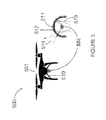
- FIG. 5 is an example embodiment of an acoustic shield.
- FIG. 6 is an example embodiment of a single extendable boom with an acoustic shield.
- FIG. 7 is an example embodiment of an active payload moment dampening system.
- the subject invention enables a reduction of noise in an audio signal detected by a UAV acoustic sensor, e.g. a microphone, during flight.
- a UAV acoustic sensor e.g. a microphone
- a UAV system 100 is comprised of a UAV 110 , which is equipped with one or more motors 106 , each for rotating a corresponding propeller 104 .
- the system 100 may be piloted remotely by a remote controller 108 or by automated instructions saved in the UAV's flight control system 210 shown in FIG. 2 .
- External environmental factors such as wind 112 , precipitation, and the like, act upon the UAV system 100 and can be accounted for by the UAV's flight control system 210 .
- the flight control system 210 determines the desired action for the UAV 110 based on the current state of the UAV 110 and the external environmental factors, e.g. the wind 112 .
- the flight control system 210 tracks the UAV's state at any given moment of time.
- This information may include position, velocity of UAV, rotational speed of propellers, rate of battery discharge, temperature, motor speed(s), velocity vector, positional vector, acceleration vector, orientation, environmental correction factors, and the like.
- This information may be used to determine an anticipated acoustic signature for each of the equipped propellers 104 , motors 106 , and any other rotational component, e.g. camera gimbal, as well as the UAV system 100 itself.
- the UAV 110 may be equipped with one or more acoustic sensors, such as a microphone 102 , for capturing sound waveforms representing acoustic signals from the UAV 110 and from other objects as well, such as other UAVs, not shown.
- a microphone 102 may have a pre-determined spatial response pattern, including but not limited to a cardioid pattern, shotgun-style, omnidirectional, or another pattern, as suits the acoustic application.
- the microphone 102 can be further mounted on an extendable boom 114 , as shown in FIG. 1 .
- the boom 114 can be manually, remotely, or automatically extended away from the downwash of the propellers. While FIG.
- FIG. 1 illustrates a downward-extended microphone 102 at the end of the boom 114 , upward, sideways and other configurations may also be used.
- multiple UAVs 110 may be used, each equipped with a microphone or microphones 102 , such that the multiple UAVs 110 , to perform the role of a boom 114 .
- an acoustic shield 510 may be used as part of the boom 114 , and may be an integral part of the microphone 102 , or the UAV body 110 , or both.
- a UAV control apparatus 200 may include a suitable processor and programming stored in non-transitory memory and executable thereby.
- Pre-determined known acoustic signatures for the particular UAV 110 (or UAVs if there are multiple ones in use) in a given configuration are stored in a database 240 .
- a flight control system 210 determines the flight state based on a flight control input module 211 or a remote pilot along with environmental flight compensation module 212 . Environmental factors including wind velocity, humidity, ambient temperature and barometric pressure, may be taken into account by the environmental flight compensation module 212 .
- a processing module 230 of the UAV control system 200 causes a processor of the processing module 230 to receive sound waveforms 220 collected from the microphone(s) 102 of FIG. 1 .
- the processing module 230 further receives flight state, control, and, or environmental data from the flight control system 210 , and uses the latter to determine a subset of likely acoustic signatures from the acoustic signature database 240 .
- the acoustic signature determination may be based on any one or more of the following: the flight control system 210 driving e.g. four motors 106 ( FIG. 1 ), to rotate e.g. four propellers 104 , at a velocity of, e.g.
- the processing module 230 receives the flight control data based on one or more of these factors, and other predetermined factors, e.g. UAV model, and computes an approximation of noise in the sound waveforms based on a compilation of stored acoustic signatures for each factor from the acoustic signature database 240 .
- the processing module 230 may then produce an output acoustic waveform 250 including the sound waveform 220 less the approximated acoustic noise identified in acoustic signature database 240 and modified based on parameters derived from the most likely acoustic signature of the acoustic signature database 240 .
- the processing module 230 may be on board the UAV 110 , or located remotely.
- the acoustic signature database 240 may be stored locally on the UAV 110 or remotely accessed by the UAV control system 200 .
- the processing module 230 or the databases 240 may be updated manually or automatically.
- the processing module 230 or the databases 240 may be updated through a memory card, or remotely over a communication link.
- a remote server performing a wireless Ethernet (Wi-Fi) or cellular packet radio update is an example of such an implementation.
- the method 300 includes step 302 of capturing at least one sound waveform a(x), representing the time-varying sound pressure at the given sensor or microphone 102 .
- the voltage or voltages may be within a variety of nominal ranges. Each voltage range may have a given relationship which corresponds to a defined sound pressure range. Each voltage range may be amplified by an amplifier (onboard or remote; not shown) or otherwise altered to enable quantization.
- a digital signal processor of the processing module 230 ( FIG. 2 ; onboard or remote) accepts the varying voltage from each of the acoustic sensors 102 and produces corresponding digitized waveforms.
- These digitized waveforms may be stored in transient or non-transient memory onboard, or transmitted remotely, as n-dimensional arrays, with two of the dimensions corresponding to quantization level and time, and thereby form a digital representation of the original analog sound pressure received by each acoustic sensor 102 .
- the relevant flight parameter(s) related to the noise suppression may be determined.
- the waveforms may be further notated to denote at least one flight parameter corresponding to the flight conditions, such as RPM, joystick positions, etc. from the UAV and/or flight control systems 200 and 210 , respectively.
- the notations may be used to select an analytic method for each signal; the analytic method may seek one or more fundamental frequencies and their harmonic features from each of the digitized sensors 102 , the signal of which is represented by the sound waveform a(x).
- the obtained noise signature f(x) is based on the determined flight parameters(s).
- the function f(x) and its frequency-domain representation f(x′) may be defined by parameters obtained from the pre-defined database 240 of FIG. 2 and may also be defined or modified based on an algorithmic function.
- the input and search criteria for the functions f(x) and f(x′) database lookup 240 may be comprised of the following:
- the acoustic noise signature f(x) may include a plurality of noise signature components, each for a particular rotational component, such as a motor or a propeller blade, of the UAV.
- Each noise signature component may include a plurality of harmonics of the rotation frequency of the corresponding rotational component, e.g. a motor or a propeller blade, a gimbal, etc.
- the obtained acoustic noise signature is applied to suppress the acoustic noise in the sound waveform.
- the acoustic noise signature may be further adjusted or conditioned.
- an initial match may be generated between the sound waveform and the acoustic noise signature, and the initial match may then be analyzed for variations of the sound waveform from the acoustic noise signature.
- the acoustic noise signature may be modified or adjusted in accordance with the analysis, e.g. acoustic noise signature may be modified based on occurrences of destructive and constructive interference in the sound waveform a(x).
- Such acoustic noise signature adjustments are intended to account for variations in amplitude, phase, peak-width, peak-profile, zero-crossing, and other time-domain characteristics in a(x), with the purpose of identifying a highest likelihood noise approximating function, f′(x), for a given sound waveform a(x).
- the UAV noise represented by the noise approximating function f′(x) may then be subtracted from the sound waveform a(x), to provide a noise-suppressed sound waveform a′(x).
- the sound waveform a(x) includes unwanted noise generated from the UAV 110 .
- a noise signature f(x) having a corresponding frequency-domain representation f(x′) is selected as explained above.
- an alignment function h(x) and its frequency-domain representation h(x′) are obtained. The latter may be configured to perform operations in frequency domain using a series of Fast-Fourier Transforms given the parameters obtained in f(x′).
- Such a function h(x) may use time-domain information to seek the leading edge (phase alignment) of a key feature, e.g. peaks, identified in f(x′), to ensure the maximum alignment of a(x) and a noise approximating function f′(x).
- the root and key harmonic frequencies in the sound waveform a(x) are determined, and sound signatures in the signature library are narrowed to the most likely subset of signatures based on the flight parameters.
- a starting match may be determined and placed in f(x) in step 384 .
- the sound waveform a(x) may be analyzed for variations of a(x) from f(x) in terms of primary parameters of peak width, phase, and expected profile of harmonic amplitudes.
- the sound waveform a(x) may also be analyzed for variations in secondary parameters, which may include destructive interference, constructive interference, root frequency drift, harmonic frequency drift, and valley frequency patterns. Based on the findings, the transform function, h(x), is obtained in step 386 .
- a system 340 for UAV noise suppression suppresses the UAV noise according to the techniques described in FIGS. 3A, 3B, and 3C above.
- the system 340 includes harmonic calculators 343 , a standing wave calculator 344 , a sample library 345 corresponding to the acoustic signature database 240 of FIG. 2 , and a dynamic multi-stage notch filter 348 .
- the system 340 can be implemented in software, hardware, or a combination of both.
- the system 340 makes use of motors 341 voltage sensors to determine individual motor RPM data and thereby determine the anticipated noise harmonic frequencies.
- a flight controller 342 operably coupled to the N motors 341 , determines current rotation frequencies RPM 1 . . . RPM N , which are communicated to the harmonic calculators 343 .
- the anticipated harmonic frequencies are matched against the UAV signature library, that is, the sample library 345 , to determine harmonic signatures H 1 . . . H N .
- Each harmonic signature H 1 . . . H N may include frequency, bandwidth, and amplitude values. This information is then used by the standing wave calculator 344 to calculate the interference pattern.
- the interference pattern comprises variations in individual harmonics to account for constructive and destructive interference, frequency drift, frequency spreading, and ultimately the parameters which define the convolution function represented by the dynamic multi-stage notch filter 348 .
- the output (OUT) of this process is a self-noise-reduced acoustic signal representation 347 of the original acoustic input (IN) signal 346 .
- the above representation of a real-time embodiment of the present invention can be easily extended to include non-real-time embodiments and signal acquisition from other means, wherein the processes of signal acquisition and signal manipulation can be separated in time and space.
- the digitized signal may be stored in a variety of formats to reduce memory or computing resources. These include, but are not limited to, WAV, MP3, AAC, AIFF, PCM, and other proprietary and non-proprietary formats.
- FIG. 4A depicts experimental results 400 on an arbitrary UAV noise signal, a(x), illustrated as a voltage signal of dB vs. time with the noise reduction algorithm applied, i.e. the addition of f(x) between 4 s and 5 s of the signal to produce a clean acoustic output signal a′(x) during that time.
- a(x) illustrated as a voltage signal of dB vs. time with the noise reduction algorithm applied, i.e. the addition of f(x) between 4 s and 5 s of the signal to produce a clean acoustic output signal a′(x) during that time.
- FIGS. 4B and 4C illustrate time evolution of sound spectra before and after noise suppression.
- the left horizontal scale depicts sound frequency in Hz
- the vertical scale depicts signal strength in dB
- the right horizontal scale depicts time in seconds.
- FIG. 4B shows a time dependence of a frequency spectrum of the sound waveform a(x) before suppression, showing some time-varying harmonics at approximately 775 Hz, 1.55 kHz, 3.1 kHz, and 6.2 kHz.
- FIG. 4C shows a time dependence of a frequency spectrum of the noise-suppressed sound waveform a′(x).
- noise harmonics have been considerably suppressed, especially the highest harmonics at 6.2 kHz and 3.1 kHz.
- noise suppression can be achieved either by phase-shifting a sample waveform or by dynamically “erasing” harmonic lines through a narrowband notch filter, or by a combination of the two.
- a UAV system 500 uses an acoustic shield 510 , which may be in a variety of form factors, mounted to the underside of a given UAV 501 similar to UAV 110 of FIG. 1 .
- the preferred embodiment is a parabolic guard 512 ( FIG. 5 ), which is coated with a lightweight sound absorbing material 511 .
- the sound absorbing material 511 is selected and configured to ensure maximum signal absorption and extraneous reflections 514 away from an embedded sound sensor 502 , while the interior of the guard 512 is designed with high sound reflecting material as to direct signals of interest towards 513 the sound sensor 502 .
- the shield 510 may be of various geometries and dimensions and is not limited to the shapes and relative sizes disclosed herein.
- the presence of a noise shield 510 modifies the time- and frequency-dependent coefficients of the transform function, h(x), which may require a different or expanded signature library 240 .
- a UAV 600 uses a boom 630 fixed to the UAV's 600 geometrical center of gravity.
- the boom 630 extends in the vertical plane so as to enable a sound sensor 620 to be moved closer to a target of interest.
- the sensor 620 is moved away from the primary noise path created from various components of the UAV 600 , such as propellers 640 and motors 650 .
- An acoustic shield 610 may be attached to the boom 630 and the sound sensor 620 system to enable acoustic dampening and enhanced beam-forming by extending intra-sensor distances.
- the boom 630 may be at a fixed length, or it may be at a plurality of lengths, including 1 cm, 10 cm, 100 cm, 1000 cm and values between, below, or beyond these ranges.
- a plurality of geometries are possible for the acoustic shield 610 including cubic, cylindrical, parabolic, spherical, and complex shapes.
- a plurality of acoustic dampening and reflecting materials and material shapes 611 may be provided.
- One embodiment includes an acoustic foam shaped into triangular wedges and offset in distances and angles as to maximally absorb and reflect desired frequency ranges away from the acoustic sensor 620 .
- the boom 630 enables a variety of new applications that extend the range of the UAV sensor and payload.
- the UAV 600 can be flown at a safe altitude, for example at an altitude amenable to maintaining a direct line of sight for reliable remote wireless control, while the payload itself can be lowered to a desired position.
- an active moment-dampening system may be used to reduce payload oscillations.
- FIG. 7 shows a UAV system 700 including a UAV 710 with an extendable boom comprised of a plurality of extension cables 720 .
- the number of cables can be 1, 2, 3, 4, or more depending on the type of control system desired, weight, power consumption, and other considerations.
- a 4-cable boom is demonstrated, wherein each cable 720 is attached to a corresponding motor 730 .
- the motor 730 is shown attached to the landing gear of the UAV [ 710 ], however, it is to be understood that the motors 730 can be placed at a plurality of locations, including on the cables themselves, on the shield 740 , and on other parts of the UAV 710 .
- the motors 730 may be under the control of the UAV's onboard flight controller, or controlled remotely.
- the motors 730 may be controlled automatically or manually.
- the motor control system may communicate with a remote controller over the UAV's existing control link, or it may have its own control link.
- the motor control system may use the UAV on-board power system, or it may have its own power system.
- An active dampening system may be enabled on the motor control system to compensate for adverse flight characteristics of a sensor payload system, including the shield 740 , being at a significant arm from the UAV's normal center of gravity datum.
- a moment-compensator may be utilized.
- the moment-compensator may dynamically adjust the length of each equipped cable 720 in response to adverse events.
- the system can also be used to provide a stability of the payload position, wherein the UAV 710 is positioned and the cable lengths 720 individually adjusted, to ensure the payload-sensor system 740 remains stationary in 3-dimensional space.
- a system of the present disclosure enables sensors to be utilized on UAVs that were not previously possible or practical.
- this system enables the use of an acoustic speaker for two-way communication.
- a sensitive magnetometer may be moved out of the UAV magnetic field.
- the boom enables accurate insertion of emergency equipment (a two-way radio, a defibrillator, etc.).
- the boom enables the UAV to maintain active data link control (at altitude) while delivering a package.
- An application for the present invention includes a UAV-mounted boom microphone and directional RF sensor that can be physically and digitally removed from the primary self-noise path and focused on the target of interest.
- the application provides the UAV boom mounting system (hardware) and control system software that uses flight characteristics obtained from the UAV's flight control system to dynamically adjust the digital acoustic filter characteristics.
- a variable comb filter can be provided that uses the RPM (or even its abstraction as control inputs) to adjust the comb widths and center frequencies based on the resonant frequencies of the noise-making components (motors, propellers).
- One embodiment of the present disclosure is primarily a hardware product employing a boom-mounted shotgun microphone, an acoustic shield, a boom extension/retraction mechanism, a wireless remote audio streaming and control protocol, and a “base station” receiver/controller. Noise cancellation is done in a post-processing software application. Another embodiment of the present disclosure builds on the hardware product and includes active noise cancellation processing on board. This is both a hardware and software solution.
Abstract
Description
-
- a. the key features of a(x) such as its peak and harmonic frequencies, frequency overlaps from multiple noise-generating components, such as
motors 106 andpropellers 104; - b. flight state information such as motor RPM, velocity vectors, compensation vectors, etc.;
- c. flight control input positions such as instructions to the flight controller, joystick positions, etc.;
- d. environmental data such as computed or actual wind vectors, relative humidity, temperature, barometric pressure, etc.; and
- e. other higher-order information about the UAV's operation (such as its geographical location) which would give rise to appropriate noise function of the noise-generating components.
- a. the key features of a(x) such as its peak and harmonic frequencies, frequency overlaps from multiple noise-generating components, such as
f′(x)=f(x)*h(x)*a(x) (1)
a′(x)=a(x)−f′(x) (2)
Claims (18)
Priority Applications (1)
| Application Number | Priority Date | Filing Date | Title |
|---|---|---|---|
| US15/849,841 US10453473B2 (en) | 2016-12-22 | 2017-12-21 | Noise-reduction system for UAVs |
Applications Claiming Priority (2)
| Application Number | Priority Date | Filing Date | Title |
|---|---|---|---|
| US201662438021P | 2016-12-22 | 2016-12-22 | |
| US15/849,841 US10453473B2 (en) | 2016-12-22 | 2017-12-21 | Noise-reduction system for UAVs |
Publications (2)
| Publication Number | Publication Date |
|---|---|
| US20180204585A1 US20180204585A1 (en) | 2018-07-19 |
| US10453473B2 true US10453473B2 (en) | 2019-10-22 |
Family
ID=62838591
Family Applications (1)
| Application Number | Title | Priority Date | Filing Date |
|---|---|---|---|
| US15/849,841 Active US10453473B2 (en) | 2016-12-22 | 2017-12-21 | Noise-reduction system for UAVs |
Country Status (1)
| Country | Link |
|---|---|
| US (1) | US10453473B2 (en) |
Cited By (3)
| Publication number | Priority date | Publication date | Assignee | Title |
|---|---|---|---|---|
| USD883141S1 (en) * | 2019-11-11 | 2020-05-05 | Qi Lin | Unmanned remote control aircraft |
| USD908587S1 (en) * | 2016-01-26 | 2021-01-26 | SZ DJI Technology Co., Ltd. | Aerial vehicle |
| WO2022268754A1 (en) | 2021-06-23 | 2022-12-29 | Airbus S.A.S | Method and system for active noise cancellation |
Families Citing this family (10)
| Publication number | Priority date | Publication date | Assignee | Title |
|---|---|---|---|---|
| CN109637517B (en) * | 2017-10-06 | 2023-05-26 | 松下电器(美国)知识产权公司 | Control device, control system, and control method |
| CN109625261B (en) * | 2017-10-06 | 2023-09-22 | 松下电器(美国)知识产权公司 | Unmanned aerial vehicle |
| US11275068B2 (en) * | 2017-10-31 | 2022-03-15 | Honeywell International Inc. | Remote gas sensing using UAVs |
| JP7149498B2 (en) * | 2018-07-26 | 2022-10-07 | パナソニックIpマネジメント株式会社 | Unmanned flying object, information processing method and program |
| JP7316700B2 (en) * | 2019-04-18 | 2023-07-28 | パナソニックIpマネジメント株式会社 | UNMANNED AIRCRAFT, CONTROL METHOD AND PROGRAM |
| CN113924609A (en) * | 2020-04-16 | 2022-01-11 | 深圳市大疆创新科技有限公司 | Audio processing method and system, movable platform and electronic equipment |
| WO2021243719A1 (en) * | 2020-06-05 | 2021-12-09 | 深圳市大疆创新科技有限公司 | Method for eliminating noise from handheld cradle head, handheld cradle head and storage medium |
| CN112487730A (en) * | 2020-10-30 | 2021-03-12 | 南京航空航天大学 | Phase angle control-based multi-rotor aircraft noise suppression method |
| WO2023053847A1 (en) * | 2021-09-30 | 2023-04-06 | Jfeアドバンテック株式会社 | Sound wave reception device, sound source bearing standardization device, and method for standardizing sound source bearing |
| CN115027675B (en) * | 2022-06-21 | 2023-05-19 | 江汉大学 | Explosion field noise measuring device based on unmanned aerial vehicle platform |
Citations (14)
| Publication number | Priority date | Publication date | Assignee | Title |
|---|---|---|---|---|
| US5687243A (en) * | 1995-09-29 | 1997-11-11 | Motorola, Inc. | Noise suppression apparatus and method |
| US5774837A (en) * | 1995-09-13 | 1998-06-30 | Voxware, Inc. | Speech coding system and method using voicing probability determination |
| US20120190315A1 (en) * | 2011-01-21 | 2012-07-26 | Cardo Systems, Inc. | Communications system for a helmet |
| US20160103202A1 (en) * | 2013-04-12 | 2016-04-14 | Hitachi, Ltd. | Mobile Robot and Sound Source Position Estimation System |
| US20160375997A1 (en) * | 2015-03-03 | 2016-12-29 | Amazon Technologies, Inc. | Unmanned aerial vehicle with a tri-wing configuration |
| US20170162215A1 (en) * | 2015-12-02 | 2017-06-08 | Wal-Mart Stores, Inc. | Systems and methods of tracking item containers at a shopping facility |
| US20170168179A1 (en) * | 2015-12-11 | 2017-06-15 | Schlumberger Technology Corporation | Resonance-based inversion of acoustic impedance of annulus behind casing |
| US20170183074A1 (en) * | 2015-12-29 | 2017-06-29 | Qualcomm Incorporated | Unmanned aerial vehicle structures and methods |
| US9715884B2 (en) * | 2013-11-15 | 2017-07-25 | Canon Kabushiki Kaisha | Information processing apparatus, information processing method, and computer-readable storage medium |
| US9738381B1 (en) * | 2016-02-23 | 2017-08-22 | General Electric Company | Industrial machine acoustic inspection using unmanned aerial vehicle |
| US20170274991A1 (en) * | 2016-03-28 | 2017-09-28 | Amazon Technologies, Inc. | Selectively thrusting propulsion units for aerial vehicles |
| US20170274993A1 (en) * | 2016-03-23 | 2017-09-28 | Amazon Technologies, Inc. | Aerial vehicle with different propeller blade configurations |
| US20180075834A1 (en) * | 2016-09-15 | 2018-03-15 | Gopro, Inc. | Noise Cancellation For Aerial Vehicle |
| US20180090134A1 (en) * | 2016-09-27 | 2018-03-29 | Vocollect, Inc. | Utilization of location and environment to improve recognition |
-
2017
- 2017-12-21 US US15/849,841 patent/US10453473B2/en active Active
Patent Citations (15)
| Publication number | Priority date | Publication date | Assignee | Title |
|---|---|---|---|---|
| US5774837A (en) * | 1995-09-13 | 1998-06-30 | Voxware, Inc. | Speech coding system and method using voicing probability determination |
| US5687243A (en) * | 1995-09-29 | 1997-11-11 | Motorola, Inc. | Noise suppression apparatus and method |
| US20120190315A1 (en) * | 2011-01-21 | 2012-07-26 | Cardo Systems, Inc. | Communications system for a helmet |
| US20160103202A1 (en) * | 2013-04-12 | 2016-04-14 | Hitachi, Ltd. | Mobile Robot and Sound Source Position Estimation System |
| US9715884B2 (en) * | 2013-11-15 | 2017-07-25 | Canon Kabushiki Kaisha | Information processing apparatus, information processing method, and computer-readable storage medium |
| US20160375997A1 (en) * | 2015-03-03 | 2016-12-29 | Amazon Technologies, Inc. | Unmanned aerial vehicle with a tri-wing configuration |
| US20170162215A1 (en) * | 2015-12-02 | 2017-06-08 | Wal-Mart Stores, Inc. | Systems and methods of tracking item containers at a shopping facility |
| US20170168179A1 (en) * | 2015-12-11 | 2017-06-15 | Schlumberger Technology Corporation | Resonance-based inversion of acoustic impedance of annulus behind casing |
| US20170183074A1 (en) * | 2015-12-29 | 2017-06-29 | Qualcomm Incorporated | Unmanned aerial vehicle structures and methods |
| US9738381B1 (en) * | 2016-02-23 | 2017-08-22 | General Electric Company | Industrial machine acoustic inspection using unmanned aerial vehicle |
| US20170274993A1 (en) * | 2016-03-23 | 2017-09-28 | Amazon Technologies, Inc. | Aerial vehicle with different propeller blade configurations |
| US20170274991A1 (en) * | 2016-03-28 | 2017-09-28 | Amazon Technologies, Inc. | Selectively thrusting propulsion units for aerial vehicles |
| US20180075834A1 (en) * | 2016-09-15 | 2018-03-15 | Gopro, Inc. | Noise Cancellation For Aerial Vehicle |
| US9984672B2 (en) * | 2016-09-15 | 2018-05-29 | Gopro, Inc. | Noise cancellation for aerial vehicle |
| US20180090134A1 (en) * | 2016-09-27 | 2018-03-29 | Vocollect, Inc. | Utilization of location and environment to improve recognition |
Cited By (3)
| Publication number | Priority date | Publication date | Assignee | Title |
|---|---|---|---|---|
| USD908587S1 (en) * | 2016-01-26 | 2021-01-26 | SZ DJI Technology Co., Ltd. | Aerial vehicle |
| USD883141S1 (en) * | 2019-11-11 | 2020-05-05 | Qi Lin | Unmanned remote control aircraft |
| WO2022268754A1 (en) | 2021-06-23 | 2022-12-29 | Airbus S.A.S | Method and system for active noise cancellation |
Also Published As
| Publication number | Publication date |
|---|---|
| US20180204585A1 (en) | 2018-07-19 |
Similar Documents
| Publication | Publication Date | Title |
|---|---|---|
| US10453473B2 (en) | Noise-reduction system for UAVs | |
| EP3161502B1 (en) | An unmanned aerial vehicle (uav) for collecting audio data | |
| US10979805B2 (en) | Microphone array auto-directive adaptive wideband beamforming using orientation information from MEMS sensors | |
| Nguyen et al. | Matthan: Drone presence detection by identifying physical signatures in the drone's rf communication | |
| Sedunov et al. | Stevens drone detection acoustic system and experiments in acoustics UAV tracking | |
| US10362392B2 (en) | Aerial acoustic sensing, acoustic sensing payload and aerial vehicle including the same | |
| EP3125237A1 (en) | Active noise cancellation apparatus and method for improving voice recognition performance | |
| JP2018534188A (en) | Active airborne sound reduction | |
| US11721352B2 (en) | Systems and methods for audio capture | |
| US10290293B2 (en) | Systems, apparatus, and methods for drone audio noise reduction | |
| WO2017083597A1 (en) | Detection and ranging systems and methods | |
| US20160379619A1 (en) | Wireless aircraft, method of cancelling noise, program for wireless aircraft | |
| US20190130889A1 (en) | Drone-based interactive and active audio system | |
| JP2014056181A (en) | Sound source direction estimation device, sound processing system, sound source direction estimation method, sound source direction estimation program | |
| JP2019536697A (en) | Unmanned aerial vehicle obstacle avoidance control method and unmanned aerial vehicle | |
| US11084583B2 (en) | Drone deployed speaker system | |
| Ishiki et al. | Design model of microphone arrays for multirotor helicopters | |
| CN109073747A (en) | A kind of avoidance obstacle method of unmanned vehicle and unmanned vehicle | |
| Simons et al. | Assessment of noise level variations of aircraft flyovers using acoustic arrays | |
| US20210041772A1 (en) | Method for suppressing vibration of gimbal, and gimbal | |
| US20210233416A1 (en) | Unmanned aircraft, information processing method, and recording medium | |
| JP7094779B2 (en) | Control device, control system and control method | |
| US11483646B1 (en) | Beamforming using filter coefficients corresponding to virtual microphones | |
| WO2020137181A1 (en) | Information processing device, information processing method, and program | |
| JP2023095030A (en) | Abnormality detecting system and abnormality detecting method |
Legal Events
| Date | Code | Title | Description |
|---|---|---|---|
| AS | Assignment |
Owner name: AIRSHARE, INC., CANADA Free format text: ASSIGNMENT OF ASSIGNORS INTEREST;ASSIGNORS:WHITTAKER, RICHARD JONATHAN;SIGOUIN, TARIQ;REEL/FRAME:044458/0524 Effective date: 20171113 |
|
| FEPP | Fee payment procedure |
Free format text: ENTITY STATUS SET TO UNDISCOUNTED (ORIGINAL EVENT CODE: BIG.); ENTITY STATUS OF PATENT OWNER: SMALL ENTITY |
|
| FEPP | Fee payment procedure |
Free format text: ENTITY STATUS SET TO MICRO (ORIGINAL EVENT CODE: MICR); ENTITY STATUS OF PATENT OWNER: SMALL ENTITY Free format text: ENTITY STATUS SET TO SMALL (ORIGINAL EVENT CODE: SMAL); ENTITY STATUS OF PATENT OWNER: SMALL ENTITY |
|
| STPP | Information on status: patent application and granting procedure in general |
Free format text: NON FINAL ACTION MAILED |
|
| STPP | Information on status: patent application and granting procedure in general |
Free format text: RESPONSE TO NON-FINAL OFFICE ACTION ENTERED AND FORWARDED TO EXAMINER |
|
| STPP | Information on status: patent application and granting procedure in general |
Free format text: NOTICE OF ALLOWANCE MAILED -- APPLICATION RECEIVED IN OFFICE OF PUBLICATIONS |
|
| STCF | Information on status: patent grant |
Free format text: PATENTED CASE |
|
| FEPP | Fee payment procedure |
Free format text: ENTITY STATUS SET TO MICRO (ORIGINAL EVENT CODE: MICR); ENTITY STATUS OF PATENT OWNER: MICROENTITY |
|
| MAFP | Maintenance fee payment |
Free format text: PAYMENT OF MAINTENANCE FEE, 4TH YEAR, MICRO ENTITY (ORIGINAL EVENT CODE: M3551); ENTITY STATUS OF PATENT OWNER: MICROENTITY Year of fee payment: 4 |
|
| MAFP | Maintenance fee payment |
Free format text: PAYMENT OF MAINTENANCE FEE UNDER 1.28(C) (ORIGINAL EVENT CODE: M1559); ENTITY STATUS OF PATENT OWNER: MICROENTITY |