US10440625B2 - Method and apparatus for performing handover in inter-vehicle communication system - Google Patents
Method and apparatus for performing handover in inter-vehicle communication system Download PDFInfo
- Publication number
- US10440625B2 US10440625B2 US15/753,780 US201615753780A US10440625B2 US 10440625 B2 US10440625 B2 US 10440625B2 US 201615753780 A US201615753780 A US 201615753780A US 10440625 B2 US10440625 B2 US 10440625B2
- Authority
- US
- United States
- Prior art keywords
- vehicle
- information
- bias value
- group
- cell
- Prior art date
- Legal status (The legal status is an assumption and is not a legal conclusion. Google has not performed a legal analysis and makes no representation as to the accuracy of the status listed.)
- Active, expires
Links
- 238000000034 method Methods 0.000 title claims abstract description 87
- 238000004891 communication Methods 0.000 title abstract description 87
- 238000013507 mapping Methods 0.000 claims description 7
- 238000009826 distribution Methods 0.000 claims description 4
- 230000005540 biological transmission Effects 0.000 description 61
- 239000011159 matrix material Substances 0.000 description 46
- 239000010410 layer Substances 0.000 description 45
- 238000010586 diagram Methods 0.000 description 28
- 238000005516 engineering process Methods 0.000 description 22
- 230000037230 mobility Effects 0.000 description 22
- 230000006870 function Effects 0.000 description 16
- 239000013598 vector Substances 0.000 description 15
- 238000005259 measurement Methods 0.000 description 14
- 238000013139 quantization Methods 0.000 description 11
- 241000760358 Enodes Species 0.000 description 8
- 101000741965 Homo sapiens Inactive tyrosine-protein kinase PRAG1 Proteins 0.000 description 6
- 102100038659 Inactive tyrosine-protein kinase PRAG1 Human genes 0.000 description 6
- 238000013461 design Methods 0.000 description 6
- 230000007774 longterm Effects 0.000 description 6
- 238000010295 mobile communication Methods 0.000 description 6
- 230000004913 activation Effects 0.000 description 5
- 230000011664 signaling Effects 0.000 description 5
- 239000000470 constituent Substances 0.000 description 4
- 230000000694 effects Effects 0.000 description 4
- 238000012545 processing Methods 0.000 description 4
- 238000011160 research Methods 0.000 description 4
- 238000003491 array Methods 0.000 description 3
- 230000009849 deactivation Effects 0.000 description 3
- 238000013468 resource allocation Methods 0.000 description 3
- 230000008054 signal transmission Effects 0.000 description 3
- 108010003272 Hyaluronate lyase Proteins 0.000 description 2
- 230000008901 benefit Effects 0.000 description 2
- 238000011161 development Methods 0.000 description 2
- 238000007726 management method Methods 0.000 description 2
- 238000012986 modification Methods 0.000 description 2
- 230000004048 modification Effects 0.000 description 2
- 230000010363 phase shift Effects 0.000 description 2
- 230000008569 process Effects 0.000 description 2
- 230000004044 response Effects 0.000 description 2
- 230000006978 adaptation Effects 0.000 description 1
- 230000000903 blocking effect Effects 0.000 description 1
- 238000004364 calculation method Methods 0.000 description 1
- 230000015556 catabolic process Effects 0.000 description 1
- 230000006835 compression Effects 0.000 description 1
- 238000007906 compression Methods 0.000 description 1
- 125000004122 cyclic group Chemical group 0.000 description 1
- 238000006731 degradation reaction Methods 0.000 description 1
- 238000009795 derivation Methods 0.000 description 1
- 238000001514 detection method Methods 0.000 description 1
- 230000002542 deteriorative effect Effects 0.000 description 1
- 238000003745 diagnosis Methods 0.000 description 1
- 230000009977 dual effect Effects 0.000 description 1
- 238000005562 fading Methods 0.000 description 1
- 239000012634 fragment Substances 0.000 description 1
- 238000007429 general method Methods 0.000 description 1
- 238000009434 installation Methods 0.000 description 1
- 238000004519 manufacturing process Methods 0.000 description 1
- 238000012544 monitoring process Methods 0.000 description 1
- 230000035515 penetration Effects 0.000 description 1
- 230000005855 radiation Effects 0.000 description 1
- 230000009467 reduction Effects 0.000 description 1
- 238000005070 sampling Methods 0.000 description 1
- 239000002356 single layer Substances 0.000 description 1
- 230000007480 spreading Effects 0.000 description 1
- 238000003892 spreading Methods 0.000 description 1
- 230000003068 static effect Effects 0.000 description 1
- 238000012546 transfer Methods 0.000 description 1
- 230000009466 transformation Effects 0.000 description 1
- 230000007704 transition Effects 0.000 description 1
- 230000000007 visual effect Effects 0.000 description 1
Images


Classifications
-
- H—ELECTRICITY
- H04—ELECTRIC COMMUNICATION TECHNIQUE
- H04W—WIRELESS COMMUNICATION NETWORKS
- H04W36/00—Hand-off or reselection arrangements
- H04W36/24—Reselection being triggered by specific parameters
-
- H—ELECTRICITY
- H04—ELECTRIC COMMUNICATION TECHNIQUE
- H04W—WIRELESS COMMUNICATION NETWORKS
- H04W24/00—Supervisory, monitoring or testing arrangements
- H04W24/10—Scheduling measurement reports ; Arrangements for measurement reports
-
- H—ELECTRICITY
- H04—ELECTRIC COMMUNICATION TECHNIQUE
- H04W—WIRELESS COMMUNICATION NETWORKS
- H04W36/00—Hand-off or reselection arrangements
- H04W36/0005—Control or signalling for completing the hand-off
- H04W36/0009—Control or signalling for completing the hand-off for a plurality of users or terminals, e.g. group communication or moving wireless networks
-
- H—ELECTRICITY
- H04—ELECTRIC COMMUNICATION TECHNIQUE
- H04W—WIRELESS COMMUNICATION NETWORKS
- H04W36/00—Hand-off or reselection arrangements
- H04W36/0005—Control or signalling for completing the hand-off
- H04W36/0083—Determination of parameters used for hand-off, e.g. generation or modification of neighbour cell lists
- H04W36/0085—Hand-off measurements
- H04W36/0094—Definition of hand-off measurement parameters
-
- H—ELECTRICITY
- H04—ELECTRIC COMMUNICATION TECHNIQUE
- H04W—WIRELESS COMMUNICATION NETWORKS
- H04W36/00—Hand-off or reselection arrangements
- H04W36/14—Reselecting a network or an air interface
-
- H—ELECTRICITY
- H04—ELECTRIC COMMUNICATION TECHNIQUE
- H04W—WIRELESS COMMUNICATION NETWORKS
- H04W36/00—Hand-off or reselection arrangements
- H04W36/16—Performing reselection for specific purposes
- H04W36/22—Performing reselection for specific purposes for handling the traffic
-
- H—ELECTRICITY
- H04—ELECTRIC COMMUNICATION TECHNIQUE
- H04W—WIRELESS COMMUNICATION NETWORKS
- H04W36/00—Hand-off or reselection arrangements
- H04W36/24—Reselection being triggered by specific parameters
- H04W36/247—Reselection being triggered by specific parameters by using coverage extension
-
- H—ELECTRICITY
- H04—ELECTRIC COMMUNICATION TECHNIQUE
- H04W—WIRELESS COMMUNICATION NETWORKS
- H04W36/00—Hand-off or reselection arrangements
- H04W36/24—Reselection being triggered by specific parameters
- H04W36/30—Reselection being triggered by specific parameters by measured or perceived connection quality data
-
- H—ELECTRICITY
- H04—ELECTRIC COMMUNICATION TECHNIQUE
- H04W—WIRELESS COMMUNICATION NETWORKS
- H04W4/00—Services specially adapted for wireless communication networks; Facilities therefor
- H04W4/30—Services specially adapted for particular environments, situations or purposes
- H04W4/40—Services specially adapted for particular environments, situations or purposes for vehicles, e.g. vehicle-to-pedestrians [V2P]
- H04W4/44—Services specially adapted for particular environments, situations or purposes for vehicles, e.g. vehicle-to-pedestrians [V2P] for communication between vehicles and infrastructures, e.g. vehicle-to-cloud [V2C] or vehicle-to-home [V2H]
-
- H—ELECTRICITY
- H04—ELECTRIC COMMUNICATION TECHNIQUE
- H04W—WIRELESS COMMUNICATION NETWORKS
- H04W36/00—Hand-off or reselection arrangements
- H04W36/03—Reselecting a link using a direct mode connection
-
- H—ELECTRICITY
- H04—ELECTRIC COMMUNICATION TECHNIQUE
- H04W—WIRELESS COMMUNICATION NETWORKS
- H04W36/00—Hand-off or reselection arrangements
- H04W36/03—Reselecting a link using a direct mode connection
- H04W36/037—Reselecting a link using a direct mode connection by reducing handover delay, e.g. latency
-
- H—ELECTRICITY
- H04—ELECTRIC COMMUNICATION TECHNIQUE
- H04W—WIRELESS COMMUNICATION NETWORKS
- H04W4/00—Services specially adapted for wireless communication networks; Facilities therefor
- H04W4/02—Services making use of location information
-
- H—ELECTRICITY
- H04—ELECTRIC COMMUNICATION TECHNIQUE
- H04W—WIRELESS COMMUNICATION NETWORKS
- H04W4/00—Services specially adapted for wireless communication networks; Facilities therefor
- H04W4/30—Services specially adapted for particular environments, situations or purposes
- H04W4/40—Services specially adapted for particular environments, situations or purposes for vehicles, e.g. vehicle-to-pedestrians [V2P]
- H04W4/46—Services specially adapted for particular environments, situations or purposes for vehicles, e.g. vehicle-to-pedestrians [V2P] for vehicle-to-vehicle communication [V2V]
Definitions
- the present invention relates to a wireless communication system and, more particularly, to a wireless communication system applied to vehicular communication.
- 3GPP LTE 3rd Generation Partnership Project Long Term Evolution
- FIG. 1 illustrates a configuration of an Evolved Universal Mobile Telecommunications System (E-UMTS) network as an exemplary wireless communication system.
- E-UMTS Evolved Universal Mobile Telecommunications System
- the E-UMTS system is an evolution of the legacy UMTS system and the 3GPP is working on the basics of E-UMTS standardization.
- E-UMTS is also called an LTE system.
- LTE Long Term Evolution
- the E-UMTS system includes a User Equipment (UE), an evolved Node B (eNode B or eNB), and an Access Gateway (AG) which is located at an end of an Evolved UMTS Terrestrial Radio Access Network (E-UTRAN) and connected to an external network.
- the eNB may transmit multiple data streams simultaneously, for broadcast service, multicast service, and/or unicast service.
- a single eNB manages one or more cells.
- a cell is set to operate in one of the bandwidths of 1.25, 2.5, 5, 10, 15 and 20 Mhz and provides Downlink (DL) or Uplink (UL) transmission service to a plurality of UEs in the bandwidth. Different cells may be configured so as to provide different bandwidths.
- An eNB controls data transmission and reception to and from a plurality of UEs. Regarding DL data, the eNB notifies a particular UE of a time-frequency area in which the DL data is supposed to be transmitted, a coding scheme, a data size, Hybrid Automatic Repeat reQuest (HARQ) information, etc. by transmitting DL scheduling information to the UE.
- HARQ Hybrid Automatic Repeat reQuest
- the eNB notifies a particular UE of a time-frequency area in which the UE can transmit data, a coding scheme, a data size, HARQ information, etc. by transmitting UL scheduling information to the UE.
- An interface for transmitting user traffic or control traffic may be defined between eNBs.
- a Core Network (CN) may include an AG and a network node for user registration of UEs.
- the AG manages the mobility of UEs on a Tracking Area (TA) basis.
- a TA includes a plurality of cells.
- WCDMA Wideband Code Division Multiple Access
- An object of the present invention is to provide a method of performing handover in a vehicle-to-vehicle communication system and an apparatus therefor.
- Another object of the present invention is to provide a method of controlling a handover scheme in units of groups in consideration of an environment of densely distributed vehicles.
- Another object of the present invention is to provide a method of solving an over-traffic problem for a cell based on mobility and density of vehicles.
- a method of performing handover by a first User Equipment may include receiving information about a first bias value from a Base Station (BS), receiving information about a second bias value from a second UE, and performing handover based on the first bias value and the second bias value.
- the first UE and the second UE may be set as the same UE group.
- the first bias value may be a bias value for the UE group and the second bias value may be a bias value for the first UE.
- the first UE may include a transceiver module configured to transmit and receive information to and from an external device, and a processor configured to control the transceiver module.
- the processor may receive information about a first bias value from a Base Station (BS) through the transceiver module, receive information about a second bias value from a second UE through the transceiver module, and perform handover based on the first bias value and the second bias value.
- the first UE and the second UE may be set as the same UE group.
- the first bias value may be a bias value for the UE group and the second bias value may be a bias value for the first UE.
- the second UE may be a representative UE of the UE group.
- the second UE may receive UE attribute information from each of all UEs in the UE group.
- the second UE may determine the second bias value for the first UE based on UE attribute information of all the UEs.
- the second UE may further determine a bias value of each of all the UEs in the UE group.
- the UE attribute information may include at least one of cell signal strength, traffic information, or mobility information.
- the first bias value may be transmitted to the first UE through a higher-layer message.
- the first bias value may be transmitted to all UEs in the UE group and may be equally set for all the UEs in the UE group.
- the UE group may be configured based on at least one of UE location distribution, demanded traffic capacity, or mobility.
- the UE group may be configured by the BS.
- the second bias value may be set based on a first ID indicator and the first ID indicator may indicate the first UE in the UE group.
- an ID indicator indicating each UE may be allocated to each of UEs in the UE group and the ID indicator for each of the UEs may be allocated by the BS or the second UE.
- the information about the second bias value may be information configured by a mapping table including the first ID indicator and the second bias value and the first UE may acquire the information about the second bias value based on the first ID indicator from the information configured by the mapping table.
- a method of performing handover in a vehicle-to-vehicle communication system and an apparatus therefor are provided.
- a method of controlling a handover scheme in units of groups in consideration of an environment in which vehicles are densely distributed is provided.
- a method of solving an over-traffic problem for a cell based on mobility and density of vehicles is provided.
- FIG. 1 is a diagram schematically illustrating a network structure of an E-UMTS as an exemplary radio communication system according to an embodiment of the present invention.
- FIG. 2 is a diagram illustrating structures of a control plane and a user plane of a radio interface protocol between a UE and an E-UTRAN based on the 3GPP radio access network specification according to an embodiment of the present invention.
- FIG. 3 is a diagram illustrating physical channels used in a 3GPP system and a general signal transmission method using the same according to an embodiment of the present invention.
- FIG. 4 is a diagram illustrating the structure of a radio frame used in an LTE system according to an embodiment of the present invention.
- FIG. 5 is a diagram showing the structure of a downlink radio frame used in an LTE system according to an embodiment of the present invention.
- FIG. 6 is a diagram showing the structure of an uplink radio frame used in an LTE system according to an embodiment of the present invention.
- FIG. 7 is a diagram showing the structure of a general multiple input multiple output (MIMO) communication system according to an embodiment of the present invention.
- MIMO multiple input multiple output
- FIG. 8 is a diagram showing a vehicle including a plurality of antenna arrays according to an embodiment of the present invention.
- FIG. 9 is a diagram showing a method of selecting a distributed antenna unit (DU) in a state in which a plurality of vehicles is concentrated, according to an embodiment of the present invention.
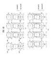
- FIG. 10 is a diagram showing an example of a DU selection combination according to an embodiment of the present invention.
- FIG. 11 is a diagram showing a DU including a plurality of antenna ports according to an embodiment of the present invention.
- FIG. 12 is a diagram illustrating an example of heterogeneous network deployment.
- FIG. 13 is a diagram illustrating an exemplary method of performing handover procedure of a UE.
- FIG. 14 is a diagram illustrating an example of Cell Range Expansion (CRE).
- CRE Cell Range Expansion
- FIG. 15 is a diagram illustrating a method of performing handover in a vehicle-to-vehicle communication system.
- FIG. 16 is a flowchart illustrating a method of selecting a distributed antenna according to an embodiment of the present invention.
- FIG. 17 is a block diagram of a UE and a BS according to an embodiment of the present invention.
- the following embodiments are proposed by combining constituent components and characteristics of the present invention according to a predetermined format.
- the individual constituent components or characteristics should be considered to be optional factors on the condition that there is no additional remark. If required, the individual constituent components or characteristics may not be combined with other components or characteristics. Also, some constituent components and/or characteristics may be combined to implement the embodiments of the present invention.
- the order of operations to be disclosed in the embodiments of the present invention may be changed to another. Some components or characteristics of any embodiment may also be included in other embodiments, or may be replaced with those of the other embodiments as necessary.
- the embodiments of the present invention can be supported by the standard documents disclosed in any one of wireless access systems, such as an IEEE 802 system, a 3rd Generation Partnership Project (3GPP) system, 3GPP Long Term Evolution (LTE) and LTE-Advanced (LTE-A) systems, and a 3GPP2 system. That is, the steps or portions, which are not described in order to make the technical spirit of the present invention clear, may be supported by the above documents. In addition, all the terms disclosed in the present document may be described by the above standard documents.
- 3GPP 3rd Generation Partnership Project
- LTE 3GPP Long Term Evolution
- LTE-A LTE-Advanced
- CDMA Code Division Multiple Access
- FDMA Frequency Division Multiple Access
- TDMA Time Division Multiple Access
- OFDMA Orthogonal Frequency Division Multiple Access
- SC-FDMA Single Carrier Frequency Division Multiple Access
- CDMA may be embodied with wireless (or radio) technology such as UTRA (Universal Terrestrial Radio Access) or CDMA2000.
- TDMA may be embodied with wireless (or radio) technology such as GSM (Global System for Mobile communications)/GPRS (General Packet Radio Service)/EDGE (Enhanced Data Rates for GSM Evolution).
- GSM Global System for Mobile communications
- GPRS General Packet Radio Service
- EDGE Enhanced Data Rates for GSM Evolution
- OFDMA may be embodied with wireless (or radio) technology such as Institute of Electrical and Electronics Engineers (IEEE) 802.11 (Wi-Fi), IEEE 802.16 (WiMAX), IEEE 802-20, and E-UTRA (Evolved UTRA).
- IEEE Institute of Electrical and Electronics Engineers
- Wi-Fi Wi-Fi
- WiMAX IEEE 802.16
- WiMAX WiMAX
- IEEE 802-20 IEEE 802-20
- E-UTRA Evolved UTRA
- unit for processing at least one function or operation, which may be implemented by hardware, software and a combination thereof.
- FIG. 2 is a diagram illustrating structures of a control plane and a user plane of a radio interface protocol between a UE and an E-UTRAN based on the 3GPP radio access network specification according to an embodiment of the present invention.
- FIG. 2 illustrates control-plane and user-plane protocol stacks in a radio interface protocol architecture conforming to a 3GPP wireless access network standard between a User Equipment (UE) and an Evolved UMTS Terrestrial Radio Access Network (E-UTRAN).
- the control plane is a path in which the UE and the E-UTRAN transmit control messages to manage calls
- the user plane is a path in which data generated from an application layer, for example, voice data or Internet packet data is transmitted.
- a PHYsical (PHY) layer at Layer 1 (L1) provides information transfer service to its higher layer, a Medium Access Control (MAC) layer.
- the PHY layer is connected to the MAC layer via transport channels.
- the transport channels deliver data between the MAC layer and the PHY layer.
- Data is transmitted on physical channels between the PHY layers of a transmitter and a receiver.
- the physical channels use time and frequency as radio resources. Specifically, the physical channels are modulated in Orthogonal Frequency Division Multiple Access (OFDMA) for Downlink (DL) and in Single Carrier Frequency Division Multiple Access (SC-FDMA) for Uplink (UL).
- OFDMA Orthogonal Frequency Division Multiple Access
- SC-FDMA Single Carrier Frequency Division Multiple Access
- the MAC layer at Layer 2 provides service to its higher layer, a Radio Link Control (RLC) layer via logical channels.
- the RLC layer at L2 supports reliable data transmission.
- RLC functionality may be implemented in a function block of the MAC layer.
- a Packet Data Convergence Protocol (PDCP) layer at L2 performs header compression to reduce the amount of unnecessary control information and thus efficiently transmit Internet Protocol (IP) packets such as IP version 4 (IPv4) or IP version 6 (IPv6) packets via an air interface having a narrow bandwidth.
- IP Internet Protocol
- IPv4 IP version 4
- IPv6 IP version 6
- a Radio Resource Control (RRC) layer at the lowest part of Layer 3 (or L3) is defined only on the control plane.
- the RRC layer controls logical channels, transport channels, and physical channels in relation to configuration, reconfiguration, and release of radio bearers.
- a radio bearer refers to a service provided at L2, for data transmission between the UE and the E-UTRAN.
- the RRC layers of the UE and the E-UTRAN exchange RRC messages with each other. If an RRC connection is established between the UE and the E-UTRAN, the UE is in RRC Connected mode and otherwise, the UE is in RRC Idle mode.
- a Non-Access Stratum (NAS) layer above the RRC layer performs functions including session management and mobility management.
- NAS Non-Access Stratum
- DL transport channels used to deliver data from the E-UTRAN to UEs include a Broadcast Channel (BCH) carrying system information, a Paging Channel (PCH) carrying a paging message, and a Shared Channel (SCH) carrying user traffic or a control message.
- BCH Broadcast Channel
- PCH Paging Channel
- SCH Shared Channel
- DL multicast traffic or control messages or DL broadcast traffic or control messages may be transmitted on a DL SCH or a separately defined DL Multicast Channel (MCH).
- UL transport channels used to deliver data from a UE to the E-UTRAN include a Random Access Channel (RACH) carrying an initial control message and a UL SCH carrying user traffic or a control message.
- RACH Random Access Channel
- Logical channels that are defined above transport channels and mapped to the transport channels include a Broadcast Control Channel (BCCH), a Paging Control Channel (PCCH), a Common Control Channel (CCCH), a Multicast Control Channel (MCCH), a Multicast Traffic Channel (MTCH), etc.
- BCCH Broadcast Control Channel
- PCCH Paging Control Channel
- CCCH Common Control Channel
- MCCH Multicast Control Channel
- MTCH Multicast Traffic Channel
- FIG. 3 illustrates physical channels and a general method for transmitting signals on the physical channels in the 3GPP system.
- the UE when a UE is powered on or enters a new cell, the UE performs initial cell search (S 301 ).
- the initial cell search involves acquisition of synchronization to an eNB. Specifically, the UE synchronizes its timing to the eNB and acquires a cell Identifier (ID) and other information by receiving a Primary Synchronization Channel (P-SCH) and a Secondary Synchronization Channel (S-SCH) from the eNB. Then the UE may acquire information broadcast in the cell by receiving a Physical Broadcast Channel (PBCH) from the eNB.
- PBCH Physical Broadcast Channel
- the UE may monitor a DL channel state by receiving a DownLink Reference Signal (DL RS).
- DL RS DownLink Reference Signal
- the UE may acquire detailed system information by receiving a Physical Downlink Control Channel (PDCCH) and receiving a Physical Downlink Shared Channel (PDSCH) based on information included in the PDCCH (S 302 ).
- PDCCH Physical Downlink Control Channel
- PDSCH Physical Downlink Shared Channel
- the UE may perform a random access procedure with the eNB (S 303 to S 306 ).
- the UE may transmit a predetermined sequence as a preamble on a Physical Random Access Channel (PRACH) (S 303 and S 305 ) and may receive a response message to the preamble on a PDCCH and a PDSCH associated with the PDCCH (S 304 and S 306 ).
- PRACH Physical Random Access Channel
- the UE may additionally perform a contention resolution procedure.
- the UE may receive a PDCCH and/or a PDSCH from the eNB (S 307 ) and transmit a Physical Uplink Shared Channel (PUSCH) and/or a Physical Uplink Control Channel (PUCCH) to the eNB (S 308 ), which is a general DL and UL signal transmission procedure.
- the UE receives Downlink Control Information (DCI) on a PDCCH.
- DCI Downlink Control Information
- the DCI includes control information such as resource allocation information for the UE. Different DCI formats are defined according to different usages of DCI.
- Control information that the UE transmits to the eNB on the UL or receives from the eNB on the DL includes a DL/UL ACKnowledgment/Negative ACKnowledgment (ACK/NACK) signal, a Channel Quality Indicator (CQI), a Precoding Matrix Index (PMI), a Rank Indicator (RI), etc.
- ACK/NACK DL/UL ACKnowledgment/Negative ACKnowledgment
- CQI Channel Quality Indicator
- PMI Precoding Matrix Index
- RI Rank Indicator
- the UE may transmit control information such as a CQI, a PMI, an RI, etc. on a PUSCH and/or a PUCCH.
- FIG. 4 illustrates a structure of a radio frame used in the LTE system.
- a radio frame is 10 ms (327200 ⁇ Ts) long and divided into 10 equal-sized subframes.
- Each subframe is 1 ms long and further divided into two slots.
- Each time slot is 0.5 ms (15360 ⁇ Ts) long.
- a slot includes a plurality of Orthogonal Frequency Division Multiplexing (OFDM) symbols or SC-FDMA symbols in the time domain by a plurality of Resource Blocks (RBs) in the frequency domain.
- OFDM Orthogonal Frequency Division Multiplexing
- RBs Resource Blocks
- one RB includes 12 subcarriers by 7 (or 6) OFDM symbols.
- a unit time during which data is transmitted is defined as a Transmission Time Interval (TTI).
- TTI may be defined in units of one or more subframes.
- the above-described radio frame structure is purely exemplary and thus the number of subframes in a radio frame, the number of slots in a subframe, or the number of OFDM symbols in a slot may vary.
- FIG. 5 illustrates exemplary control channels included in a control region of a subframe in a DL radio frame.
- a subframe includes 14 OFDM symbols.
- the first one to three OFDM symbols of a subframe are used for a control region and the other 13 to 11 OFDM symbols are used for a data region according to a subframe configuration.
- reference characters R 1 to R 4 denote RSs or pilot signals for antenna 0 to antenna 3 .
- RSs are allocated in a predetermined pattern in a subframe irrespective of the control region and the data region.
- a control channel is allocated to non-RS resources in the control region and a traffic channel is also allocated to non-RS resources in the data region.
- Control channels allocated to the control region include a Physical Control Format Indicator Channel (PCFICH), a Physical Hybrid-ARQ Indicator Channel (PHICH), a Physical Downlink Control Channel (PDCCH), etc.
- PCFICH Physical Control Format Indicator Channel
- PHICH Physical Hybrid-ARQ Indicator Channel
- PDCCH Physical Downlink Control Channel
- the PCFICH is a physical control format indicator channel carrying information about the number of OFDM symbols used for PDCCHs in each subframe.
- the PCFICH is located in the first OFDM symbol of a subframe and configured with priority over the PHICH and the PDCCH.
- the PCFICH includes 4 Resource Element Groups (REGs), each REG being distributed to the control region based on a cell Identity (ID).
- One REG includes 4 Resource Elements (REs).
- An RE is a minimum physical resource defined by one subcarrier by one OFDM symbol.
- the PCFICH is set to 1 to 3 or 2 to 4 according to a bandwidth.
- the PCFICH is modulated in Quadrature Phase Shift Keying (QPSK).
- QPSK Quadrature Phase Shift Keying
- the PHICH is a physical Hybrid-Automatic Repeat and request (HARQ) indicator channel carrying an HARQ ACK/NACK for a UL transmission. That is, the PHICH is a channel that delivers DL ACK/NACK information for UL HARQ.
- the PHICH includes one REG and is scrambled cell-specifically.
- An ACK/NACK is indicated in one bit and modulated in Binary Phase Shift Keying (BPSK).
- BPSK Binary Phase Shift Keying
- the modulated ACK/NACK is spread with a Spreading Factor (SF) of 2 or 4.
- SF Spreading Factor
- a plurality of PHICHs mapped to the same resources form a PHICH group. The number of PHICHs multiplexed into a PHICH group is determined according to the number of spreading codes.
- a PHICH (group) is repeated three times to obtain a diversity gain in the frequency domain and/or the time domain.
- the PDCCH is a physical DL control channel allocated to the first n OFDM symbols of a subframe.
- n is 1 or a larger integer indicated by the PCFICH.
- the PDCCH occupies one or more CCEs.
- the PDCCH carries resource allocation information about transport channels, PCH and DL-SCH, a UL scheduling grant, and HARQ information to each UE or UE group.
- the PCH and the DL-SCH are transmitted on a PDSCH. Therefore, an eNB and a UE transmit and receive data usually on the PDSCH, except for specific control information or specific service data.
- Information indicating one or more UEs to receive PDSCH data and information indicating how the UEs are supposed to receive and decode the PDSCH data are delivered on a PDCCH.
- CRC Cyclic Redundancy Check
- RNTI Radio Network Temporary Identity
- Information about data transmitted in radio resources e.g. at a frequency position
- transport format information e.g. a transport block size, a modulation scheme, coding information, etc.
- C is transmitted in a specific subframe, a UE within a cell monitors, that is, blind-decodes a PDCCH using its RNTI information in a search space. If one or more UEs have RNTI “A”, these UEs receive the PDCCH and receive a PDSCH indicated by “B” and “C” based on information of the received PDCCH.
- FIG. 6 illustrates a structure of a UL subframe in the LTE system.
- a UL subframe may be divided into a control region and a data region.
- a Physical Uplink Control Channel (PUCCH) including Uplink Control Information (UCI) is allocated to the control region and a Physical uplink Shared Channel (PUSCH) including user data is allocated to the data region.
- the middle of the subframe is allocated to the PUSCH, while both sides of the data region in the frequency domain are allocated to the PUCCH.
- Control information transmitted on the PUCCH may include an HARQ ACK/NACK, a CQI representing a downlink channel state, an RI for Multiple Input Multiple Output (MIMO), a Scheduling Request (SR) requesting UL resource allocation.
- MIMO Multiple Input Multiple Output
- SR Scheduling Request
- FIG. 7 is a diagram showing the structure of a general multiple input multiple output (MIMO) communication system according to an embodiment of the present invention.
- MIMO multiple input multiple output
- MIMO refers to a method using multiple transmit antennas and multiple receive antennas to improve data transmission/reception efficiency. Namely, a plurality of antennas is used at a transmitter or a receiver of a wireless communication system so that capacity can be increased and performance can be improved. MIMO may also be referred to as multi-antenna in this disclosure.
- MIMO technology does not depend on a single antenna path in order to receive a whole message. Instead, MIMO technology completes data by combining data fragments received via multiple antennas.
- the use of MIMO technology can increase data transmission rate within a cell area of a specific size or extend system coverage at a specific data transmission rate.
- MIMO technology can be widely used in mobile communication terminals and relay nodes. MIMO technology can overcome a limited transmission capacity encountered with the conventional single-antenna technology in mobile communication.
- FIG. 7 illustrates the configuration of a typical MIMO communication system.
- a transmitter has NT transmit (Tx) antennas and a receiver has NR receive (Rx) antennas.
- Tx transmit
- Rx receive
- Use of a plurality of antennas at both the transmitter and the receiver increases a theoretical channel transmission capacity, compared to the use of a plurality of antennas at only one of the transmitter and the receiver.
- Channel transmission capacity increases in proportion to the number of antennas. Therefore, transmission rate and frequency efficiency are increased.
- Ro is the smaller of NT and NR.
- R i min( N T ,N R ) [Equation 1]
- a MIMO communication system with four Tx antennas and four Rx antennas may theoretically achieve a transmission rate four times that of a single antenna system. Since the theoretical capacity increase of the MIMO wireless communication system was verified in the mid-1990s, many techniques have been actively developed to increase data transmission rate in real implementations. Some of these techniques have already been reflected in various wireless communication standards including standards for 3rd generation (3G) mobile communications, next-generation wireless local area networks, etc.
- 3G 3rd generation
- the transmission power-controlled transmission information vector ⁇ may be expressed as shown in Equation 4 below, using a diagonal matrix P of transmission power.
- NT transmission signals x 1 , x 2 , . . . , x N T to be actually transmitted may be configured by multiplying the transmission power-controlled information vector ⁇ by a weight matrix W.
- the weight matrix functions to appropriately distribute the transmission information to individual antennas according to transmission channel states, etc.
- the transmission signals x 1 , x 2 , . . . , x N T are represented as a vector X, as shown in Equation 5 below.
- w ij denotes a weight of an i-th Tx antenna and a j-th piece of information.
- W is referred to as a weight matrix or a precoding matrix.
- the physical meaning of the rank of a channel matrix is the maximum number of different pieces of information that can be transmitted on a given channel. Therefore, the rank of a channel matrix is defined as the smaller of the number of independent rows and the number of independent columns in the channel matrix. Accordingly, the rank of the channel matrix is not larger than the number of rows or columns of the channel matrix.
- the rank of the channel matrix H (rank(H)) is restricted as shown in Equation 6 below. rank( H ) ⁇ min( N T ,N R ) [Equation 6]
- a different piece of information transmitted in MIMO is referred to as a transmission stream or stream.
- a stream may also be called a layer. It is thus concluded that the number of transmission streams is not larger than the rank of channels, i.e. the maximum number of different pieces of transmittable information.
- the channel matrix H is expressed as shown in Equation 7 below. # of streams ⁇ rank( H ) ⁇ min( N T ,N R ) [Equation 7]
- # of streams denotes the number of streams. It should be noted that one stream may be transmitted through one or more antennas.
- One or more streams may be mapped to a plurality of antennas in many ways. This method may be described as follows depending on MIMO schemes. If one stream is transmitted through a plurality of antennas, this may be regarded as spatial diversity. When a plurality of streams is transmitted through a plurality of antennas, this may be spatial multiplexing. A hybrid scheme of spatial diversity and spatial multiplexing may be contemplated.
- CoMP Coordinated Multi-Point
- CoMP transmission schemes may be classified into CoMP-Joint Processing (CoMP-JP) called cooperative MIMO characterized by data sharing, and CoMP-Coordinated Scheduling/Beamforming (CoMP-CS/CB).
- CoMP-JP CoMP-Joint Processing
- CoMP-CS/CB CoMP-Coordinated Scheduling/Beamforming
- a UE may instantaneously receive data simultaneously from eNBs that perform CoMP transmission and may combine the received signals, thereby increasing reception performance (Joint Transmission (JT)).
- JT Joint Transmission
- one of the eNBs participating in the CoMP transmission may transmit data to the UE at a specific time point (Dynamic Point Selection (DPS)).
- DPS Dynamic Point Selection
- a UE may receive data instantaneously from one eNB, that is, a serving eNB by beamforming.
- eNBs may receive a PUSCH signal from a UE at the same time (Joint Reception (JR)).
- JR Joint Reception
- eNBs may make a decision as to whether to use CoMP-CS/CB.
- CSI channel state information reporting
- a MIMO transmission scheme is categorized into open-loop MIMO operated without CSI and closed-loop MIMO operated based on CSI.
- each of the eNB and the UE may be able to perform beamforming based on CSI in order to obtain multiplexing gain of MIMO antennas.
- the eNB transmits RSs to the UE and commands the UE to feed back CSI measured based on the RSs through a PUCCH or a PUSCH.
- CSI is divided into three types of information: an RI, a PMI, and a CQI.
- RI is information on a channel rank as described above and indicates the number of streams that can be received via the same time-frequency resource. Since RI is determined by long-term fading of a channel, it may be generally fed back at a cycle longer than that of PMI or CQI.
- PMI is a value reflecting a spatial characteristic of a channel and indicates a precoding matrix index of the eNB preferred by the UE based on a metric of signal-to-interference plus noise ratio (SINR).
- SINR signal-to-interference plus noise ratio
- CQI is information indicating the strength of a channel and indicates a reception SINR obtainable when the eNB uses PMI.
- An advanced system such as an LTE-A system considers additional multi-user diversity through multi-user MIMO (MU-MIMO). Due to interference between UEs multiplexed in an antenna domain in MU-MIMO, the accuracy of CSI may significantly affect interference with other multiplexed UEs as well as a UE that reports the CSI. Accordingly, more accurate CSI than in single-user MIMO (SU-MIMO) should be reported in MU-MIMO.
- SU-MIMO single-user MIMO
- the LTE-A standard has determined to separately design a final PMI as a long-term and/or wideband PMI, W1, and a short-term and/or subband PMI, W2.
- Equation 8 a long-term covariance matrix of channels expressed as Equation 8 may be used for hierarchical codebook transformation that configures one final PMI with W1 and W2.
- W norm( W 1 W 2) [Equation 8]
- W2 is a short-term PMI, which is a codeword of a codebook reflecting short-term channel information
- W is a codeword of a final codebook
- norm(A) is a matrix obtained by normalizing each column of matrix A to 1.
- the codewords are designed so as to reflect correlation characteristics between established channels, if cross-polarized antennas are densely arranged, for example, the distance between adjacent antennas is equal to or less than half a signal wavelength.
- the cross-polarized antennas may be divided into a horizontal antenna group and a vertical antenna group and the two antenna groups are co-located, each having the property of a uniform linear array (ULA) antenna.
- ULA uniform linear array
- Equation 10 a rank-1 codeword designed in the above manner may be given as Equation 10.
- the codebook configurations are designed to reflect channel correlation properties generated when cross polarized antennas are used and when a space between antennas is dense, for example, when a distance between adjacent antennas is less than a half of signal wavelength.
- the cross polarized antennas may be categorized into a horizontal antenna group and a vertical antenna group. Each antenna group has the characteristic of a Uniform Linear Array (ULA) antenna and the two groups are co-located.
- ULA Uniform Linear Array
- a correlation between antennas of each group has characteristics of the same linear phase increment and a correlation between antenna groups has characteristics of phase rotation. Consequently, since a codebook is a value obtained by quantizing a channel, it is necessary to design a codebook such that characteristics of a channel are reflected.
- a rank-1 codeword generated by the aforementioned configurations is shown in Equation 10 below.
- a codeword is expressed as an N T ⁇ 1 vector where NT is the number of Tx antennas and the codeword is composed of an upper vector X i (k) and a lower vector ⁇ j X i (k), representing the correlation characteristics of the horizontal and vertical antenna groups, respectively.
- X i (k) is expressed as a vector having the linear phase increment property, reflecting the correlation characteristics between antennas in each antenna group.
- a discrete Fourier transform (DFT) matrix may be used.
- An advanced system such as an LTE-A system considers achievement of an additional multi-user diversity by the use of MU-MIMO. Due to the existence of interference channels between UEs multiplexed in an antenna domain in MU-MIMO, the accuracy of CSI may significantly affect interference with other multiplexed UEs as well as a UE that reports the CSI. Accordingly, more accurate CSI than in SU-MIMO should be reported in MU-MIMO.
- the eNBs may be theoretically regarded as forming a MIMO system with antennas distributed geographically. That is, even when MU-MIMO is implemented in JT, highly accurate CSI is required to avoid interference between CoMP-scheduled UEs as in a single cell MU-MIMO operation.
- CoMP CB that is, to avoid interference with a serving cell caused by a neighbor cell, accurate CSI is needed.
- a UE needs to report an additional CSI feedback in order to increase the accuracy of CSI feedback.
- the CSI feedback is transmitted on a PUCCH or a PUSCH to an eNB.
- FIG. 8 is a diagram showing a vehicle including a plurality of antenna arrays according to an embodiment of the present invention.
- the number of uses of the above-described wireless communication system and service categories using the wireless communication system have increased.
- QoS quality of service
- a wireless communication system needs to support wireless services having good quality to moving UEs when a plurality of UEs or users (hereinafter, collectively referred to as a UE) desires to view multimedia content while using public transportation or when a plurality of UEs of passengers riding in a personal vehicle traveling on an expressway uses different wireless communication services.
- a conventional wireless communication system has some limits in provision of a service to a UE in consideration of high-speed movement or mobility.
- a system network needs to be revolutionized.
- a new system for maintaining compatibility with an existing network infrastructure without influencing the existing network infrastructure needs to be designed.
- a large-sized antenna array may be mounted in a vehicle such that the vehicle acquires large array gain, thereby providing services having good quality to UEs located in the vehicle even in a state in which the vehicle moves at a high speed.
- data received through a central unit hereinafter, CU
- CU central unit
- a vehicular MIMO system may be considered.
- the vehicle can prevent communication performance from being lowered due to penetration loss having an average value of 20 dB.
- the vehicle uses receive (rx) antennas greater in number than the number of UEs using a system, large array gain can be easily obtained and reception diversity can be obtained by ensuring a distance between the receive antennas. That is, it is possible to provide a service to a UE moving at a high speed without additionally designing a network through the vehicular MIMO system.
- a vehicle may include a plurality of antennas 810 , 820 , 830 , 840 , 850 and 860 mounted therein.
- the locations and number of the plurality of antennas 810 , 820 , 830 , 840 , 850 and 860 may be changed according to vehicle design.
- the below-described configuration is equally applicable even when the locations and number of the plurality of antennas 810 , 820 , 830 , 840 , 850 and 860 mounted in the vehicle are changed, and the present invention is not limited to the below-described embodiments. That is, the present invention is applicable to antennas having various shapes and radiation patterns according to the locations of the plurality of antennas 810 , 820 , 830 , 840 , 850 and 860 .
- signals for distributed antenna units (DUs) of the vehicle may be controlled through a central unit (CU) 870 .
- the CU 870 of the vehicle may control the signals for the DUs 810 , 820 , 830 , 840 , 850 and 860 mounted in the vehicle to receive a signal from a base station while maximizing reception diversity and to prevent wireless connection between the base station and the vehicle in a state in which the vehicle moves at a high speed.
- the vehicle may be a UE having a plurality of antennas or a relay for relaying a signal.
- the vehicle may provide a service having good quality to a plurality of UEs located in the vehicle through control and relay of the signal received through the CU 870 .
- FIG. 9 is a diagram showing a method of selecting a distributed antenna unit (DU) in a state in which a plurality of vehicles is concentrated, according to an embodiment of the present invention.
- a vehicle may include a plurality of DUs and a CU 870 for controlling the DUs.
- a plurality of vehicles 920 - 1 , 920 - 2 and 920 - 3 may be concentrated in a narrow area.
- the plurality of vehicles 920 - 1 , 920 - 2 and 920 - 3 may be concentrated in a narrow area upon city driving or upon a traffic jam.
- the DU located at the right side of the first vehicle 920 - 1 may be adjacent to the DU located at the left side of the second vehicle 920 - 2 and thus the beams for these DUs may not be easily distinguished. That is, since DUs located adjacent to each other receive signals undergoing similar channel environments, a plurality of DUs may be likely to receive the same beam or not to receive a signal due to blocking of obstacles.
- the vehicles 920 - 1 , 920 - 2 and 920 - 3 may selectively control activation or deactivation of the DUs based on the density of neighboring vehicles. For example, when a beam transmitted from a first base station 910 - 1 to a first vehicle 920 - 1 is received, the first vehicle 920 - 1 may activate only the DUs located at the left side of the first vehicle 920 - 1 and deactivate the remaining DUs of the first vehicle 920 - 1 , to be distinguished from the adjacent second vehicle 920 - 2 .
- the first vehicle 920 - 1 may determine whether vehicles are concentrated using a position information reception unit (e.g., a GPS) or a proximity sensor.
- whether the DUs are deactivated may be determined based on a threshold value based on density of vehicles.
- a threshold value may be a criterion value for determining activation or deactivation. That is, a criterion for determining whether the vehicles 920 - 1 , 920 - 2 and 920 - 3 are concentrated may be changed and is not limited to the above-described embodiment.
- the third vehicle 920 - 3 may activate two DUs located at the front side of the third vehicle 920 - 3 in order to receive the beam from the second base station 910 - 2 . That is, the vehicles 920 - 1 , 920 - 2 and 920 - 3 may selectively activate/deactivate the DUs thereof to distinguish the beam received through the activated DUs thereof from the beams capable of being received by adjacent vehicles. Therefore, beams passing through independent paths experiencing different clusters are received, thereby improving beam reception performance.
- the vehicles may feed information on activation and deactivation of the DUs back to the base station as described above.
- the above-described information may be fed back along with channel state information (CSI) fed back from the vehicles to the base station.
- CSI channel state information
- a transmission end needs to obtain information on a channel and to accurately measure a suitable beam and gain obtained upon using the beam based on the information.
- a reception end e.g., a UE or a vehicle
- may feed channel information back to the transmission end e.g., the base station
- the transmission end e.g., the base station
- an implicit CSI reporting scheme or an explicit CSI reporting scheme may be used as a CSI reporting scheme. That is, an implicit CSI reporting scheme or an explicit CSI reporting scheme may be used as a CSI reporting scheme of a massive MIMO environment.
- the implicit CSI reporting scheme may refer to a scheme of analyzing information on a channel measured by a reception end and reporting only information substantially necessary to generate a beam, without reporting the information on the channel measured by the reception end. That is, only necessary information may be fed back based on a predefined or predetermined value.
- the explicit CSI reporting scheme may refer to a scheme of reporting information maximally approximating to a measured value to a transmission end without a process of analyzing a channel measured by a reception end.
- a method of quantizing a MIMO channel represented in a matrix or performing SVD operation may be used in the channel information.
- the implicit CSI report information may include a precoding matrix index (PMI), a channel quality indicator (CQI), rank information (RI), etc.
- the explicit CSI report information may include channel coefficient quantization & quantization index feedback, MIMO matrix or vector quantization & quantization index feedback, channel covariance matrix feedback, Eigen matrix feedback (transmission of Eigen vectors and/or Eigen values of channel matrix), etc.
- the implicit CSI reporting scheme can reduce signal overhead as compared to the explicit CSI reporting scheme, since only necessary information is extracted and fed back.
- a UE receives a pilot signal (reference signal) for channel estimation from a base station and calculates and reports channel state information (CSI) to the base station.
- the base station transmits data to the UE based on the CSI fed back from the UE.
- the CSI fed back by the UE may include a channel quality indicator (CQI), a precoding matrix index (PMI), a rank indicator (RI), etc.
- CQI feedback may be radio channel quality information provided to the base station for the purpose of providing information regarding which modulation and coding scheme (MCS) is applied when the base station transmits data (for link adaptation).
- MCS modulation and coding scheme
- the UE may feed back a high CQI value and the base station may apply a relatively high modulation order and a low channel coding rate and transmit data. Otherwise, the UE may feed back a low CQI value and the base station may apply a relatively low modulation order and a high channel coding rate and transmit data.
- PMI feedback may be feedback of preferred precoding matrix information provided to the base station for the purpose of providing information regarding which MIMO precoding is applied when the base station includes multiple antennas mounted therein.
- the UE may estimate a downlink MIMO channel between the base station and the UE from a pilot signal and provide information indicating which MIMO precoding is applied to the base station through PMI feedback.
- only linear MIMO precoding representable in a matrix in a configuration of a PMI was considered.
- the base station and the UE share a codebook composed of a plurality of precoding matrices and each MIMO precoding matrix in the codebook has a unique index. Accordingly, the UE may feed back an index corresponding to a most preferred MIMO precoding matrix in the codebook as PMI, thereby minimizing the amount of feedback information of the UE.
- RI feedback may be feedback of information on the number of preferred transport layers provided to the base station for the purpose of providing information on the number of transport layers preferred by the UE when each of the base station and the UE includes multiple antennas mounted therein and thus multilayer transmission through spatial multiplexing is possible.
- the RI since the base station should know which precoding is applied to each layer according to the number of transport layers, the RI may be closely related with the PMI.
- a PMI codebook may be configured based on single-layer transmission and then a PMI may be defined and fed back per layer.
- the amount of PMI/RI feedback information is significantly increased as the number of transport layers increases.
- a PMI codebook according to the number of transport layers was defined. That is, N matrices having a size of Nt ⁇ R may be defined in the codebook, for R-layer transmission (here, R denotes the number of layers, Nt denotes the number of transmit antenna ports, and N denotes the size of a codebook). At this time, the size of the codebook may be defined regardless of the number of transport layers. As a result, when the PMI/RI is defined in such a structure, the number R of transport layers becomes equal to the rank value of the precoding matrix (Nt ⁇ R matrix) and thus may be referred to as a rank indicator (RI).
- RI rank indicator
- CSI may be obtained in an overall system frequency region or some frequency regions (e.g., Wideband CSI, Subband CSI).
- some frequency regions e.g., Wideband CSI, Subband CSI.
- OFDMA orthogonal frequency division multiple access
- the below-described PMI/RI may not be limited to the index value of a precoding matrix represented in an Nt ⁇ R matrix and the rank value of a precoding matrix like a PMI/RI of a wireless communication system.
- the below-described PMI indicates preferred MIMO precoder information among MIMO precoders applicable to a transmission end and the precoder is not limited to a linear precoder represented in a matrix as in a conventional wireless system.
- the below-described RI has a broader meaning than the RI in the conventional wireless communication system and may include all feedback information indicating the number of preferred transport layers without being limited thereto.
- the PMI value may not include only one index.
- a final PMI is divided into W1 which is a long term and/or wideband (WB) PMI and W2 which is a short term and/or subband (SB) PMI, thereby designing a PMI having a dual structure.
- W wideband
- SB subband
- a final MIMO precoding matrix may be derived by only combining two indices (WB PMI & SB PMI).
- SU-MIMO single user-MIMO
- SU-MIMO single user-MIMO
- data of one UE may be scheduled in the same time/frequency domain. That is, if information is transmitted to and received from one UE by MIMO, only scheduling information of one UE may be included in one time/frequency domain.
- MU-MIMO multiuser-MIMO
- data of a plurality of UEs may be scheduled together in one time/frequency domain.
- the data is multiplexed in the same time/frequency domain, thereby obtaining additional gain.
- the UE may feed CSI thereof back to the base station and the base station may schedule a user based on the CSI fed back from the plurality of UEs, thereby optimizing a system.
- each vehicle may feed combination information related to the number and locations of DUs activated in the vehicle and channel state information back to a base station. That is, interference with other vehicles and reception performance may be changed according to the number and locations of DUs activated in each vehicle and each vehicle needs to feed information on the activated DUs back to the base station.
- the base station may acquire an effective channel of each vehicle based on the received channel state information and the activated DU information and transmit data.
- the base station needs to acquire more accurate channel information.
- a method of feeding back activated DU information at a vehicle will be described.
- the method may be identically applied even to communication of a single vehicle in which a plurality of DUs is densely distributed. More specifically, configuration and definition of each DU may be differently applied.
- the structure of a communication device may be divided into a Remote Radio Head (RRH) including a Radio Frequency (RF) stage, a Modem (PHY/MAC/PDCP/RRC/NAS), and an AP.
- RRH Remote Radio Head
- RF Radio Frequency
- PHY/MAC/PDCP/RRC/NAS Modem
- the DU may be defined as one communication device (or system) or a normal antenna unit.
- the DU when the DU is configured only by the RF stage or the RRH, the DU may perform the function of the normal antenna unit.
- the DU when the DU has a structure of the RF stage or more, the DU may be defined as an independent communication device (or system).
- the structure of the RF stage or more may refer to a structure including the function of RRH and a part of the function of the modem.
- the structure of the RF stage or more may refer to a structure including the function of the RRH, the function of the modem, and the function of the AP. That is, the DU may be an antenna unit included in a vehicle, which performs a simple antenna function.
- the DU may be defined as a virtual UE as one communication device (or system).
- the DU may be equally applied even to a situation in which virtual UEs are densely distributed in communication of a single vehicle.
- the DU may include a plurality of antennas.
- the DU may include a plurality of antennas.
- on/off of a plurality of antennas included in the DU may be individually controlled by the DU as the virtual UE. That is, each of a plurality of DUs in a single-vehicle communication system may require a method of performing communication in a situation in which the DUs are densely distributed as virtual UEs.
- each of the DUs may include a plurality of antennas.
- each of the DUs may individually control on/off of each of the plural antennas.
- the description may be identically applied to a UE including a plurality of antennas or other devices which include a plurality of antennas and operate based on the antennas.
- the description may be identically applied even to communication of a single vehicle as the case in which the DU operates as a virtual UE and is not limited to the following embodiments.
- FIG. 10 is a diagram showing an example of a DU selection combination according to an embodiment of the present invention.
- an implicit CSI reporting scheme or an explicit CSI reporting scheme may be used as a CSI reporting scheme.
- effective channel information may be changed according to the number and locations of activated DUs.
- a UE may feed back CSI.
- cooperative communication may be performed in consideration of mutual interference.
- each UE may select DUs to be activated from among the plurality of DUs included therein, thereby reducing interference with the other vehicles or UEs.
- channel information to be reported by the vehicle may be changed according to the number and locations of activated DUs among the plurality of DUs and thus a channel information reporting method considering the same may be necessary.
- the channel information reported by the vehicle may include channel state information and DU index set information combined according to the number and locations of activated DUs among the plurality of DUs included in the vehicle.
- the channel state information may be explicitly reported in consideration of the DU index set information.
- the explicitly reported channel state information may include at least one of the channel coefficient, quantization & quantization index feedback, MIMO matrix or vector quantization & quantization index feedback, channel covariance matrix feedback and Eigen matrix feedback (transmission of Eigen vectors and/or Eigen values of channel matrix).
- the channel information fed back by the vehicle may include at least one of the DU index set information and the channel state information. That is, the channel information fed back by the vehicle may include both or one of the DU index set information and the channel state information, without being limited to the above-described embodiment.
- the channel information fed back by the vehicle may include explicit channel state information in consideration of the DU index set as described above, without being limited thereto.
- the vehicle may report the DU index set information and implicit channel state information to the base station and the base station may acquire final effective channel information using the implicit channel state information and the DU index set information.
- the base station may receive the channel information of each of the plurality of vehicles. That is, the base station may receive the DU index set information and the channel state information fed back by each of the plurality of vehicles. At this time, the base station may acquire effective channel information using the received DU index set information and channel state information. The base station may transmit data to the vehicles using the acquired effective channel information.
- the DU index set information may differ between the vehicles.
- the DU index set information may be differently set based on the number and locations of activated DUs among the plurality of DUs included in the vehicle.
- the vehicle may include four DUs 1010 , 1020 , 1030 and 1040 at corner regions thereof.
- the number and locations of DUs included in the vehicle may be differently set and is not limited to the above-described embodiment.
- each vehicle may feed the number and locations of DUs included therein back to the base station.
- each vehicle may feed information on the number and locations of activated DUs among the DUs included therein back to the base station.
- the base station may acquire the DU information of each vehicle through higher layer signaling or another path, without being limited to the above-described embodiment.
- FIG. 10( a ) shows the case where only one of the four DUs 1010 , 1020 , 1030 and 1040 included in the vehicle is activated.
- different combinations may be configured according to selected DUs. More specifically, whether each of the DUs 1010 , 1020 , 1030 and 1040 included in the vehicle is activated may be indicated through a matrix or an index. At this time, if only the DU located at the front left side of the vehicle is activated, the DU index may be [1 0 0 0]. If only one DU included in the vehicle is activated using the same method, the DU index may be represented by [0 1 0 0], [0 0 1 0] or [0 0 0 1].
- the DU index set information may include the above-described four pieces of DU index information.
- the vehicle may feed information indicating that only one of the four DUs 1010 , 1020 , 1030 and 1040 is activated back to the base station.
- the vehicle may include the four pieces of DU index information in the DU index set information and feed the DU index set information back to the base station along with the channel state information.
- the base station may acquire effective channel information based on the DU index information and perform downlink data transmission.
- the vehicle may feed the DU index set information considering both the number and locations of DUs included therein back to the base station.
- the number of cases of selecting M i (M i ⁇ N i ) DUs to be activated among the DUs included in one vehicle is shown in Equation 11 below. N i C M i [Equation 11]
- Equation 12 the total number of cases of DU combinations selectable from one vehicle is shown in Equation 12 below.
- the vehicle may be deactivated not to cause interference with the other vehicles.
- the vehicle may feed the DU index set information including 2 N i pieces of DU index information back to the base station.
- the base station may determine an effective channel using the fed-back DU index set information and channel state information.
- FIG. 10( b ) shows DU index information which is differently set according to the number and locations of activated DUs among the four DUs 1010 , 1020 , 1030 and 1040 of the vehicle. That is, the DU index may be determined based on the number and locations of activated DUs among the DUs included in the vehicle and the DU index information may be fed back to the base station as DU index set information.
- the vehicle may transmit the channel state information to the base station as an explicit CSI report.
- the explicit CSI report may include MIMO matrix quantization.
- MIMO matrix quantization is shown in Equation 13 below.
- h i elements configuring the matrix may be a scalar value by the number of antennas in each DU, quantization resolution, etc.
- h i may be a row vector or a column vector.
- a MIMO matrix may be represented by horizontally stacking h i , not vertically stacking h i as in Equation 13. That is, the base station, which has received the explicitly reported CSI and the selectable DU index set, may combine and use the effective channel information of the vehicle using the information for downlink transmission.
- FIG. 11 is a diagram showing a DU including a plurality of antenna ports according to an embodiment of the present invention.
- each vehicle may include DU index set information and channel state information in channel information and feed the channel information back to the base station.
- the DU index set may be configured as antenna port group (sub grouping or antenna port grouping) information per DU.
- one vehicle may include four DUs composed of 2/2/4/4 physical antennas.
- the total number of physical antennas included in each DU may be 12.
- the vehicle may generate channel state information based on the total number of physical antennas.
- the vehicle may feed information indicating the antenna port of the DU, to which each physical antenna is mapped, back to the base station through the DU index set information.
- the base station may map the antenna port index using the received DU index set information and the channel state information and transmit data while controlling interference between the vehicles.
- FIG. 12 is a diagram illustrating an example of heterogeneous network deployment.
- a heterogeneous environment in which various cells coexist in a short range is considered. More specifically, to stably ensure a data service such as a multimedia service in a future-generation mobile communication system, a hierarchical cell structure or a heterogeneous cell structure in which pico cells or femto cells as micro cells for low-power/short-range communication are co-existent in a macro cell based homogeneous network has been introduced.
- adding macro cells to conventional eNode B deployment is inefficient in terms of cost and complexity relative to improved system performance.
- a heterogeneous network environment as illustrated in FIG. 12 may be considered.
- an eNode B that manages and covers a macro cell is defined as a Macro eNode B (MeNB) and a UE operating within a macro cell managed by an MeNB is defined as a Macro UE (MUE).
- MeNB Macro eNode B
- MUE Macro UE
- PeNB Pico eNode B
- PUE Pico UE
- An eNode B that manages and covers a femto cell is defined as a Femto eNode B (FeNB) and a UE operating within a femto cell managed by an FeNB is defined as a Femto UE (FUE).
- FeNB Femto eNode B
- FUE Femto UE
- a plurality of micro cells may be coexist in one macro cell.
- the micro cells are allocated resources by cell coordination and provide services to UEs using the resources.
- cell selection may be performed based on a method for satisfying load balancing without changing actual transmission power.
- an offset is used without actually controlling transmission power in order to maintain load balancing, necessity for a method of compensating for performance degradation generated by inter-cell interference in an expanded cell area is increasing.
- the heterogeneous network environment may be configured by a network in which a micro cell is present within coverage of a macro cell.
- a micro cell such as a pico cell or a femto cell
- usage of the micro cell such as a pico cell or a femto cell is not particularly restricted, generally, the pico cell may be used in a communication shadow area which is not covered by the macro cell alone or an area requiring a large amount of data services, a so-called hot zone.
- the femto cell may be generally used in, for example, an office or household.
- a cell may be categorized into an Open Access (OA) cell and a Closed Subscriber Group (CSG) cell according to accessibility of a user.
- the CSG cell is basically intended to be accessible only to members belonging to a CSG.
- the micro cell may be the OA cell or the CSG cell.
- a state of a UE may be classified into an RRC connected state and an RRC idle state according to whether the UE is connected to RRC.
- UE-specific Discontinuous Reception may be configured by a Non-Access Stratum (NAS).
- NAS Non-Access Stratum
- DRX may mean a function for controlling the UE to stop a reception operation and enter a sleep mode in order to reduce power consumption of the UE.
- the UE may perform cell selection and cell reselection procedures in order to discover a suitable cell as a serving cell for the UE among neighbor cells.
- the cell reselection procedure may mean a procedure for moving to the best cell in a state in which the UE performs cell selection.
- the UE may monitor System Information (SI) transmitted by a serving cell.
- SI System Information
- the serving cell means a cell on which the UE has camped.
- Camp-on may mean a state in which the UE monitors SI and paging information after completing cell selection and reselection procedures.
- the UE may monitor a paging channel in the RRC idle state.
- the UE may transition to the RRC connected state from the RRC idle state.
- the UE may transmit and receive unicast data.
- the UE may configure UE-specific DRX defined by a Media Access Control (MAC) layer of an eNB in the RRC connected state and perform operation.
- the UE may monitor a paging channel, System Information Block Type 1 (SIB1), SI, a control channel, and the like.
- SIB1 System Information Block Type 1
- the UE may perform monitoring at a cycle different from that of the RRC idle state (generally, at a cycle shorter than that of the RRC idle state).
- the eNB may transmit information for configuring operation of the UE so as to enable the UE to acquire channel information.
- the UE may report Channel Quality Information (CQI), measurement information, etc. to the eNB according to the configured information.
- CQI Channel Quality Information
- the eNB may hand over the UE to the neighbor cell.
- a cell to which the UE is handed over may be another eNB having the same frequency band (hereinafter, an intra-frequency eNB) as the serving cell, the same eNB or another eNB having a different frequency band (hereinafter, an inter-frequency eNB) from the serving cell, or an eNB using a different wireless transmission scheme (hereinafter, inter-Radio Access Technologies (RAT) eNB) from the serving cell.
- RAT Inter-Radio Access Technologies
- FIG. 13 is a diagram illustrating an exemplary method of performing handover procedure of a UE.
- the UE may be handed over to a neighbor cell from a serving cell based on control of the eNB.
- FIG. 13 illustrates an example of a method in which the UE is handed over. More specifically, the UE may perform neighbor cell measurement for handover, cell addition, or cell reselection (S 1310 ). That is, upon generating a handover triggering event while measuring radio channel states of a serving cell and a neighbor cell, the UE may transmit a measurement report message including measurement values to a serving cell (S 1320 ).
- the serving cell Upon receiving the measurement report message for handover from the UE, the serving cell transmits a handover request message to a target cell for handover in order to initiate a handover operation (S 1330 ).
- the target cell transmits a handover request ACK message in response to the handover request message to the serving cell (S 1340 ).
- the serving cell transmits a handover command message to the UE and, upon receiving the handover command message, the UE starts a handover operation to the target cell (S 1350 ).
- the UE may measure the following three types of values in the neighbor cell measurement process.
- RSRP Reference Signal Received Power
- RSRQ Reference Signal Received Quality
- the triggering event by which the UE transmits the measurement report message to a serving cell may be as follows.
- Event A1 Serving cell becomes better than absolute threshold.
- Event A3 Neighbor cell becomes offset better than serving cell.
- Event A4 Neighbor cell becomes better than absolute threshold.
- Event A5 Serving cell becomes worse than absolute threshold and neighbor cell becomes better than absolute threshold.
- 3GPP TS 36.331 the above-described events are disclosed in more detail in 3GPP TS 36.331 and may refer to the contents of 3GPP TS 36.331.
- FIG. 14 is a diagram illustrating an example of Cell Range Expansion (CRE).
- CRE Cell Range Expansion
- CRE refers to increasing cell coverage of a micro cell in order to obtain network load balancing gain. If coverage of the micro cell increases, the number of UEs that can be accommodated within coverage may also increase. Load balancing may be performed when traffic load of multiple cells is unfairly distributed.
- a CRE bias may refer to an offset which is added to signal strength of a cell in order to apply CRE.
- An MUE may be handed over to a micro cell based on Equation 14 indicated below. In more detail, the MUE may be handed over to the micro cell when the condition satisfying Equation 14 is maintained for a predetermined time.
- S mc +S b >S mm Equation 14
- Smc is signal strength of a micro cell
- Smm is signal strength of a macro cell
- Sb is a CRE bias. For example, as Sb increases, a probability that the MUE is handed over to the micro cell increases and coverage of the micro cell is increased.
- CRE is technology of handing over, to a PeNB, an MUE which is near to the PeNB and thus experiences severe interference from the PeNB among MUEs connected to an MeNB in a heterogeneous network structure.
- CRE mitigates the effect of existing interference and achieves load balancing between cells within the system, as described above.
- the RSRP of an MeNB having high transmission power may be higher than the RSRP of a PeNB having low transmission power in a system structure.
- an MUE may not perform handover to the PeNB. Accordingly, it is necessary to implement CRE based on a new criterion as indicated by Equation 15, for reliable CRE in a cell area in which an MeNB is coexist with a PeNB.
- an offset is a value set for a UE by higher-layer signaling.
- the UE may perform CRE to a PeNB having low transmission power.
- FIG. 14 illustrates an example of CRE technology.
- an MeNB and a PeNB are deployed in a corresponding system.
- the outermost dotted lines represent a cell area of the MeNB and the innermost solid lines represent a cell area of the PeNB.
- the middle dotted lines represent an area in which an MUE may perform handover (or CRE) from the cell area of the MeNB to the cell area of the PeNB.
- the MUE determines whether the sum of a pico RSRP of the PeNB and an offset is smaller than a macro RSRP of the MeNB. If the sum of the pico RSRP and the offset is larger than the macro RSRP during RSRP measurement, the MUE performs handover from the MeNB to the PeNB. Thus, the MUE may be changed to a PUE.
- variables used in a handover procedure may be used for the CRE bias.
- the variables in the handover procedure include Ocn and Ocs.
- Ocn is a cell-specific offset value added to a measurement value of an adjacent cell and
- Ocs is a cell-specific offset value added to a measurement value of a serving cell.
- Default values of Ocn and Ocs may be set to 0 and Ocn and Ocs may be transmitted through an RRC message.
- Ocn and Ocs may be transmitted through a cell-specific message and, if Ocn and Ocs are configured to have different values with respect to respective UEs, Ocn and Ocs may be transmitted through a UE-specific message.
- FIG. 15 is a diagram illustrating a method of performing handover in a vehicle-to-vehicle communication system.
- communication may be performed based on the vehicle-to-vehicle communication system.
- a description will be given based on a vehicle including a DU, the description may be identically applied to a UE including a plurality of antennas or other devices which include a plurality of antennas and operate based on the antennas, as wireless communication system(s), and is not limited to embodiments described below.
- a high data rate service needs to be provided.
- a plurality of vehicles may be densely located in a narrow area.
- the case in which a plurality of vehicles is densely distributed in a narrow area may be caused by traffic jam or other reasons.
- the dense vehicles tend to move with similar mobility in groups. Then, since the dense vehicles may select the same specific cell, over-traffic may occur in the cell.
- groups of vehicles may be configured in vehicle-to-vehicle communication and handover may be performed in units of groups.
- Groups of vehicles may be configured based on vehicles having similar vehicular attributes.
- vehicular attributes may be determined based on at least one of location distribution, demanded traffic capacity, or mobility information of each vehicle. That is, vehicles having similar attributes may be set as one vehicle group and handover may be performed in groups.
- the above-described CRE technology may be proposed as a method of increasing coverage of a micro cell in order to acquire load balancing gain of a network.
- the CRE bias is determined by an eNB and is indicated to a vehicle using higher-layer signaling, it may be difficult to dynamically configure the CRE bias. That is, it may be limited to cope with demanded traffic capacity with respect to a plurality of dynamically varying vehicles or each dynamically varying vehicle.
- a method for acquiring a traffic off-loading effect by handing over some vehicles in an over-traffic generated cell to another cell through cooperation between vehicles within a vehicle group.
- an eNB may set a first bias value for densely distributed vehicles within a vehicle group in one cell through a higher-layer message.
- a plurality of vehicles may be set as one vehicle group.
- the vehicle group may be determined based on at least one of location distribution, demanded traffic capacity, or mobility of each vehicle, as mentioned above.
- a vehicle group for multiple vehicles may be configured based on other vehicular properties.
- a vehicle group may be a set of vehicles having similar properties and is not limited to the above-described embodiment.
- the higher-layer message may be a message transmitted and received through an RRC layer.
- the vehicle may exchange the higher-layer message with the eNB.
- the first bias value may be a bias value for the vehicle group. That is, the first bias value may be a group-dedicated CRE bias value.
- the first bias value may be equally set for all vehicles in the vehicle group.
- the vehicle group may be configured by the eNB.
- the eNB may set the first bias value through a cell-specific message with respect to a plurality of vehicles included in a vehicle group configured thereby. That is, the eNB may provide the same CRE bias value to a plurality of vehicles in the same vehicle group as the group-dedicated CRE bias value.
- the vehicle group may be configured based on vehicle-to-vehicle communication.
- information about the vehicle group configured based on vehicle-to-vehicle communication may be reported to the eNB through a representative vehicle or at least one of vehicles in the vehicle group.
- the eNB may set the first bias value which is the group-dedicated CRE bias value for the vehicle group based on the reported information about the vehicle group.
- plural vehicles in the vehicle group may exchange vehicular attribute information of each of the plural vehicles in the vehicle group.
- the vehicular attribute information may be information based on at least one of cell signal strength, mobility information, or demanded traffic capacity of each vehicle.
- each of the plural vehicles transmits the above information to a representative vehicle of the vehicle group and the representative vehicle may share the information within the vehicle group, so that the information may be exchanged between the vehicles.
- the plural vehicles may exchange the information with each other within the vehicle group through cooperative communication. That is, the plural vehicles within the vehicle group may exchange the vehicular attribute information and an information exchange scheme is not limited to the above-described embodiment.
- the representative vehicle may determine a second bias value based on the vehicular attribute information of each of the vehicles and inform each vehicle in the vehicle group of the determined second bias value.
- one or more representative vehicles may be present in one vehicle group. That is, the second bias value for all vehicles in the group may be determined by the one representative vehicle.
- a plurality of representative vehicles may configure the second bias value with respect to each of a part of plural vehicles in the group and a second bias value configuration method is not limited to the above-described embodiment.
- the second bias value may be a UE-dedicated CRE bias value. That is, the second bias value may be a specific CRE bias value for each of the vehicles in the vehicle group.
- the second bias value may be differently set with respect to the plural vehicles in the vehicle group.
- the second bias value for each of the plural vehicles in the vehicle group may be determined based on vehicular attribute information of each of the plural vehicles. That is, the representative vehicle may receive the vehicular attribute information from each of the vehicles and inform each of the plural vehicles of information about the second bias value.
- vehicle 1 (UE 1 , 1510 ), vehicle 2 (UE 2 , 1520 ), vehicle 3 (UE 3 , 1530 ), vehicle 4 (UE 4 , 1540 ), and vehicle 5 (UE 5 , 1550 ) may be set as one vehicle group (or UE group).
- an eNB may provide information about a first bias value as group-dedicated CRE bias information to vehicles 1 to 5 ( 1510 , 1520 , 1530 , 1540 , and 1550 ) in one vehicle group. That is, vehicles 1 to 5 ( 1510 , 1520 , 1530 , 1540 , and 1550 ) may acquire the information about the same first bias value.
- Vehicular attribute information for vehicles 1 to 5 may differ.
- vehicle 3 to 5 1530 , 1540 , and 1550
- vehicle 1 ( 1510 ) and vehicle 2 ( 1520 ) move in different directions and thus vehicular attributes for mobility may differ. That is, the vehicular attribute information for each of plural vehicles in a vehicle group may be variously configured and is not limited to the above-described embodiment.
- the second bias value which is the vehicle-dedicated CRE bias value
- a representative vehicle may determine that vehicles 3 to 5 ( 1530 , 1540 , and 1550 ) requiring a high data rate have almost the same vehicle mobility. That is, in FIG. 15 , since vehicles 3 to 5 ( 1530 , 1540 , and 1550 ) among a plurality of densely distributed vehicles in the vehicle group move in the same direction, the second bias value may be set with respect to vehicles 3 to 5 ( 1530 , 1540 , and 1550 ) based on mobility information of the vehicles.
- the representative vehicle may acquire vehicular attribute information about each of the plural vehicles in the vehicle group and a vehicular attribute information acquisition method is not limited to the above-described embodiment.
- the representative vehicle may set the second bias value corresponding to a different value for each vehicle with respect to vehicle 3 ( 1530 ), vehicle 4 ( 1540 ), and vehicle 5 ( 1550 ) as the vehicle-dedicated CRE bias value in consideration of mobility of vehicles 3 to 5 ( 1530 , 1540 , and 1550 ).
- the representative vehicle may set the same second bias value for vehicles 3 to 5 ( 130 , 1540 , and 1550 ) under the determination that mobilities of vehicles 3 to 5 ( 1530 , 1540 , and 1550 ) are the time.
- the representative vehicle may differently set the second bias value in consideration of a minute mobility difference between vehicles 3 to 5 ( 1530 , 1540 , and 1550 ).
- the representative vehicle may set the second bias value with respect to each vehicle and identically or differently set the second bias value based on a vehicular attribute.
- the second bias value set method is not limited to the above-described embodiment. Through this, traffic off-loading between cells may be acquired. Equation 16 may indicate a detailed operation of a handover procedure based on the above-described first bias and second bias values.
- S i,j may be a cell signal strength of a j-th cell of an i-th vehicle
- G i,j may be a first bias (group-dedicated) value of the j-th cell of the i-th vehicle
- U i,j may be a second bias (UE-dedicated CRE bias) value of the j-th cell of the i-th vehicle.
- a CRE bias value of legacy LTE is expressed as one value (G i,j +U i,j ) without distinguishing between G i,j and U i,j .
- the above value may be determined by the eNB and may be indicated through RRC signaling.
- the first bias value G i,j may be set as the group-dedicated CRE bias value by the eNB as in a conventional manner.
- the representative vehicle may set the second bias value U i,j as a different value for each vehicle based on vehicular attribute information of each of plural vehicles according to vehicle-to-vehicle communication.
- a final CRE bias value may be determined by a combination of the first bias value and the second bias value and each vehicle may determine whether to be handed over to another cell, based on Equation 16.
- plural vehicles in a vehicle group may report attribute information thereof to the eNB and then the eNB may additionally set the second UE-dedicated CRE bias value based on the attribute information and inform the vehicles of the second UE-dedicated CRE bias value.
- the above vehicle based scheme may be efficient in order to immediately cope with the demanded traffic capacity of each vehicle in consideration of dynamic variation of the vehicles, the scheme is not limited to the above-described embodiment.
- each vehicle in a vehicle group may set a prescheduled CRE bias offset value based on a vehicle ID indicator (or a UE ID indicator) in the group, assigned to each vehicle, and determine a final vehicle-dedicated CRE bias value based on the CRE bias offset value.
- each vehicle in the vehicle group may be assigned a unique vehicle ID indicator (or UE ID indicator).
- a scheme of indicating the vehicles is not limited to the above-described embodiment. That is, indicators for identifying plural vehicles in the vehicle group may be present and the scheme of indicating the vehicles is not limited to the above-described embodiment.
- the eNB may configure a vehicle ID indicator and inform each vehicle of the vehicle ID indicator.
- the eNB may configure the vehicle ID indicator for each vehicle based on cooperative communication between vehicles. That is, indicators for distinguishing between plural vehicles in the vehicle group may be configured and a method of configuring the vehicle ID indicator is not limited to the above-described embodiment.
- each vehicle in a vehicle group may acquire information about the second bias value (UE-dedicated CRE bias) based on the vehicle ID indicator.
- a mapping table as shown in Table 1 may be configured based on the ID indicator of each vehicle in the plural vehicles in the vehicle group.
- Each vehicle in the plural vehicles in the vehicle group may receive the first bias value (group-dedicated CRE bias) from the eNB.
- each vehicle of the plural vehicles in the vehicle group may receive information about the following mapping table from the representative vehicle and acquire the second bias (UE-dedicated CRE bias value) from the mapping table based on the vehicle ID indicator allocated thereto.
- the second bias value may be set as a CRE bias offset in Table 1.
- a final UE-dedicated CRE bias of a vehicle having a vehicle ID indicator (UE ID indicator) set to i may be determined as indicated in Equation 17.
- UE-dedicated CRE bias G i + ⁇ i [Equation 17]
- G i may be a first bias (group-dedicated) value of an i-th vehicle and ⁇ i may be a second bias value (CRE bias offset) of the i-th vehicle.
- FIG. 16 is a flowchart illustrating a method of selecting a distributed antenna according to an embodiment of the present invention.
- a first vehicle may receive information about a first bias value from an eNB (S 1610 ).
- the first vehicle may be a vehicle included in a vehicle group.
- the vehicle group may be configured by the eNB and vehicles having related or similar characteristics may be set as one vehicle group.
- the first bias value may be a CRE bias value for the vehicle group. That is, the first bias value may be acquired from the eNB as a value set based on the vehicle group.
- the first bias value may be equally set for all vehicles in the vehicle group and a first bias value setting method is not limited to the above-described embodiment.
- the first vehicle may receive information about a second bias value from a second vehicle (or UE) (S 1620 ).
- the second vehicle may be a representative vehicle of the vehicle group.
- the second vehicle may receive vehicular attribute information from each of plural vehicles in the vehicle group and determine the second bias value for each of the plural vehicles based on the attribute information. That is, the second bias value may be differently set with respect to each of the plural vehicles in the vehicle group as a vehicle-specific CRE bias value.
- the second bias value may be configured by taking into consideration the vehicular attribute information for each of the plural vehicles and a second bias value setting method is not limited to the above-described embodiment.
- the first vehicle may perform handover based on the first bias value and the second bias value (S 1630 ).
- the CRE bias value for each of the plural vehicles in the vehicle group based on a vehicular attribute such as mobility of a vehicle.
- a final CRE bias value for a vehicle may be determined using the first bias value corresponding to a group-specific value and the second bias value corresponding to an offset value as a vehicle-specific value and a vehicle may perform handover to another cell.
- the over-traffic problem can be solved as described above.
- FIG. 17 is a block diagram of a UE and a BS according to an embodiment of the present invention.
- a UE is described as a component of a wireless communication system, the UE may have the same meaning as a vehicle as mentioned previously.
- the wireless communication system may include a BS 10 and at least one UE 20 .
- the BS 10 may be a transmission device and the UE 20 may be a reception device.
- the UE 20 may be a transmission device and the BS 10 may be a reception device.
- the BS 10 may include a processor 11 for controlling each unit of the BS 10 , a memory 12 for storing information, and an RF unit 13 for transmitting and receiving a signal.
- the processor 11 of the BS 10 may be a unit for performing the above-described methods or procedures described with reference to FIGS. 1 to 16 .
- the memory 12 of the BS 10 may be connected to the processor 11 and may store various information controlled by the processor 11 .
- the BS 10 may perform communication with an external device using the RF unit 13 .
- the external device may be the UE.
- the external device may be the above-described vehicle.
- the external device may be a fixed device or a device and is not limited to the above-described embodiment. That is, the BS 10 may be a device capable of performing communication with another device corresponding to the external device and is not limited to the above-described embodiment.
- the UE 20 may include a processor 21 , a memory 22 , and an RF unit 23 .
- the processor 21 of the UE 20 may be a unit for performing the above-described methods or procedures described with reference to FIGS. 1 to 16 .
- the memory 22 of the UE 20 may be connected to the processor 21 and may store various information controlled by the processor 21 .
- the UE 20 may perform communication with an external device using the RF unit 23 .
- the external device may be the BS 10 .
- the external device may be another vehicle.
- the external device may be a fixed device or a device and is not limited to the above-described embodiment. That is, the UE 20 may be a device capable of performing communication with another device corresponding to the external device and is not limited to the above-described embodiment.
- the BS 10 and/or the UE 20 may include one or plural antennas.
- the wireless communication system may be the above-described MIMO system.
- the UE 20 may correspond to the aforementioned vehicle. That is, one vehicle may be one UE 20 and components of the UE 20 may be components included in the vehicle.
- the method according to the embodiments of the present invention may be implemented by one or more Application Specific Integrated Circuits (ASICs), Digital Signal Processors (DSPs), Digital Signal Processing Devices (DSPDs), Programmable Logic Devices (PLDs), Field Programmable Gate Arrays (FPGAs), processors, controllers, microcontrollers, or microprocessors.
- ASICs Application Specific Integrated Circuits
- DSPs Digital Signal Processors
- DSPDs Digital Signal Processing Devices
- PLDs Programmable Logic Devices
- FPGAs Field Programmable Gate Arrays
- processors controllers, microcontrollers, or microprocessors.
- the method according to the embodiments of the present invention may be implemented in the form of modules, procedures, functions, etc. performing the above-described functions or operations.
- Software code may be stored in a memory unit and executed by a processor.
- the memory unit may be located at the interior or exterior of the processor and may transmit and receive data to and from the processor via various known means.
Landscapes
- Engineering & Computer Science (AREA)
- Computer Networks & Wireless Communication (AREA)
- Signal Processing (AREA)
- Mobile Radio Communication Systems (AREA)
Abstract
Description
R i=min(N T ,N R) [Equation 1]
s=└s 1 ,s 2 , . . . ,s N
{circumflex over (s)}=[ŝ 1 ,ŝ 2 , . . . ,ŝ N
rank(H)≤min(N T ,N R) [Equation 6]
# of streams≤rank(H)≤min(N T ,N R) [Equation 7]
W=norm(W1W2) [Equation 8]
N
S mc +S b >S mm [Equation 14]
Pico RSRP+offset>Macro RSRP [Equation 15]
S 3,1 +G 3,1 +U 3,1 <S 3,2 +G 3,2 +U 3,2 [Equation 16]
| TABLE 1 | |||
| Vehicle (or UE) ID indicator | CRE bias offset (Δi) | ||
| 1 | 3 | ||
| 7 | 5 | ||
| 3 | 8 | ||
| 4 | 12 | ||
| . . . | . . . | ||
UE-dedicated CRE bias=G i+Δi [Equation 17]
Claims (15)
Priority Applications (1)
| Application Number | Priority Date | Filing Date | Title |
|---|---|---|---|
| US15/753,780 US10440625B2 (en) | 2015-08-21 | 2016-06-02 | Method and apparatus for performing handover in inter-vehicle communication system |
Applications Claiming Priority (3)
| Application Number | Priority Date | Filing Date | Title |
|---|---|---|---|
| US201562207931P | 2015-08-21 | 2015-08-21 | |
| US15/753,780 US10440625B2 (en) | 2015-08-21 | 2016-06-02 | Method and apparatus for performing handover in inter-vehicle communication system |
| PCT/KR2016/005864 WO2017034131A1 (en) | 2015-08-21 | 2016-06-02 | Method and apparatus for performing handover in inter-vehicle communication system |
Publications (2)
| Publication Number | Publication Date |
|---|---|
| US20180270727A1 US20180270727A1 (en) | 2018-09-20 |
| US10440625B2 true US10440625B2 (en) | 2019-10-08 |
Family
ID=58100552
Family Applications (1)
| Application Number | Title | Priority Date | Filing Date |
|---|---|---|---|
| US15/753,780 Active 2036-07-09 US10440625B2 (en) | 2015-08-21 | 2016-06-02 | Method and apparatus for performing handover in inter-vehicle communication system |
Country Status (2)
| Country | Link |
|---|---|
| US (1) | US10440625B2 (en) |
| WO (1) | WO2017034131A1 (en) |
Families Citing this family (5)
| Publication number | Priority date | Publication date | Assignee | Title |
|---|---|---|---|---|
| KR102313027B1 (en) * | 2017-06-23 | 2021-10-15 | 현대자동차주식회사 | vehicle and controlling method of vehicle |
| FR3107413B1 (en) * | 2020-02-17 | 2022-01-28 | Commissariat Energie Atomique | Resource Allocation Method for Spread Spectrum Communication System |
| US11152994B1 (en) * | 2020-05-27 | 2021-10-19 | Apple Inc. | Communication of channel state information (CSI) in wireless networks |
| JP7422029B2 (en) * | 2020-07-29 | 2024-01-25 | 本田技研工業株式会社 | Communication system, information processing device, information processing method, mobile object, method for controlling a mobile object, and program |
| US20220349997A1 (en) * | 2021-04-29 | 2022-11-03 | Qualcomm Incorporated | Intra-vehicle radar handover |
Citations (26)
| Publication number | Priority date | Publication date | Assignee | Title |
|---|---|---|---|---|
| KR20080102201A (en) | 2006-02-16 | 2008-11-24 | 모토로라 인코포레이티드 | Handover between radio networks |
| KR20110138961A (en) | 2010-06-22 | 2011-12-28 | 삼성전자주식회사 | Method of communication for mobile terminal, pico base station and macro base station in heterogeneous network |
| KR20120071881A (en) | 2010-12-23 | 2012-07-03 | 한국전자통신연구원 | Apparatus and method for group commutication |
| US20120176925A1 (en) * | 2011-01-10 | 2012-07-12 | Mediatek Inc. | Method for determining an instance for performing a channel state information measurement and communications apparatuses utilizing the same |
| KR20120080514A (en) | 2011-01-07 | 2012-07-17 | 주식회사 팬택 | Apparatus and method of performing cell selection in wireless communication system |
| US20130114434A1 (en) * | 2011-11-04 | 2013-05-09 | Research In Motion Limited | Apparatus and method for adaptive transmission during almost blank subframes in a wireless communication network |
| US20130163529A1 (en) * | 2011-12-21 | 2013-06-27 | Qualcomm Incorporated | Methods and apparatus for assignment dependent downlink channel processing for wireless networks |
| US20130229953A1 (en) * | 2011-08-16 | 2013-09-05 | Samsung Electronics Co., Ltd. | Apparatus and method for indicating synchronization signals in a wireless network |
| US20130281089A1 (en) * | 2012-04-23 | 2013-10-24 | Accelera Mobile Broadband, Inc. | Interference management and network performance optimization in small cells |
| US20140198659A1 (en) * | 2013-01-14 | 2014-07-17 | Qualcomm Incorporated | Cell range expansion elasticity control |
| US20140302853A1 (en) * | 2012-11-30 | 2014-10-09 | Telefonaktiebolaget L M Ericsson (Publ) | Network node, user equipment, methods therein, computer programs and computer-readable storage mediums to expand or shrink a coverage area of a cell |
| US20150009848A1 (en) * | 2012-03-01 | 2015-01-08 | Ntt Docomo, Inc. | Radio communication system, base station, user terminal, and communication control method |
| US20150023319A1 (en) * | 2013-07-19 | 2015-01-22 | Lg Electronics | Method and apparatus for transmitting user equipment group information in wireless communication system |
| US20150065192A1 (en) * | 2012-05-11 | 2015-03-05 | Huawei Technologies Co., Ltd. | Method, Device, and System for Configuring Cell Range Expansion Bias |
| US20150111609A1 (en) * | 2012-05-07 | 2015-04-23 | Chrysostomos Koutsimanis | Methods and arrangements for controlling transmit power in a radio base station |
| US20150124733A1 (en) * | 2012-06-08 | 2015-05-07 | Lg Electronics Inc. | Method for controlling interference in wireless communication system and apparatus therefor |
| US20150131599A1 (en) * | 2012-07-24 | 2015-05-14 | Huawei Technologies Co., Ltd. | Method for transmitting and receiving downlink control information, serving node and user equipment |
| US20150146638A1 (en) * | 2012-07-27 | 2015-05-28 | Ntt Docomo, Inc. | Radio communication system and radio base station |
| US20150163718A1 (en) * | 2012-08-27 | 2015-06-11 | Huawei Technologies Co., Ltd. | Method for determining cell handover and base station |
| US20150195057A1 (en) * | 2012-08-01 | 2015-07-09 | Nokia Solutions And Networks Oy | Cell-Specific Reference Signal Interference Cancellation Improvement |
| US20150208423A1 (en) * | 2012-06-21 | 2015-07-23 | Telefonaktiebolaget L M Ericsson (Publ) | Method for setting a first number of subframes with reduced power for downlink transmission of a first cell |
| US20150249961A1 (en) * | 2012-11-16 | 2015-09-03 | Huawei Technologies Co., Ltd. | Access method and device |
| US20150373614A1 (en) * | 2014-03-19 | 2015-12-24 | Futurewei Technologies, Inc. | System and method for ue-specific offloading |
| US20160057666A1 (en) * | 2013-03-29 | 2016-02-25 | Alcatel Lucent | Method, apparatus, and system for biasing adjustment of cell range expansion |
| US20160286561A1 (en) * | 2014-04-14 | 2016-09-29 | Telefonaktiebolaget L M Ericsson (Publ) | Method and apparatus for coordinating inter-cell interference |
| US20170041085A1 (en) * | 2015-08-06 | 2017-02-09 | Lg Electronics Inc. | Method and user equipment for removing interference in wireless communication system |
-
2016
- 2016-06-02 US US15/753,780 patent/US10440625B2/en active Active
- 2016-06-02 WO PCT/KR2016/005864 patent/WO2017034131A1/en active Application Filing
Patent Citations (26)
| Publication number | Priority date | Publication date | Assignee | Title |
|---|---|---|---|---|
| KR20080102201A (en) | 2006-02-16 | 2008-11-24 | 모토로라 인코포레이티드 | Handover between radio networks |
| KR20110138961A (en) | 2010-06-22 | 2011-12-28 | 삼성전자주식회사 | Method of communication for mobile terminal, pico base station and macro base station in heterogeneous network |
| KR20120071881A (en) | 2010-12-23 | 2012-07-03 | 한국전자통신연구원 | Apparatus and method for group commutication |
| KR20120080514A (en) | 2011-01-07 | 2012-07-17 | 주식회사 팬택 | Apparatus and method of performing cell selection in wireless communication system |
| US20120176925A1 (en) * | 2011-01-10 | 2012-07-12 | Mediatek Inc. | Method for determining an instance for performing a channel state information measurement and communications apparatuses utilizing the same |
| US20130229953A1 (en) * | 2011-08-16 | 2013-09-05 | Samsung Electronics Co., Ltd. | Apparatus and method for indicating synchronization signals in a wireless network |
| US20130114434A1 (en) * | 2011-11-04 | 2013-05-09 | Research In Motion Limited | Apparatus and method for adaptive transmission during almost blank subframes in a wireless communication network |
| US20130163529A1 (en) * | 2011-12-21 | 2013-06-27 | Qualcomm Incorporated | Methods and apparatus for assignment dependent downlink channel processing for wireless networks |
| US20150009848A1 (en) * | 2012-03-01 | 2015-01-08 | Ntt Docomo, Inc. | Radio communication system, base station, user terminal, and communication control method |
| US20130281089A1 (en) * | 2012-04-23 | 2013-10-24 | Accelera Mobile Broadband, Inc. | Interference management and network performance optimization in small cells |
| US20150111609A1 (en) * | 2012-05-07 | 2015-04-23 | Chrysostomos Koutsimanis | Methods and arrangements for controlling transmit power in a radio base station |
| US20150065192A1 (en) * | 2012-05-11 | 2015-03-05 | Huawei Technologies Co., Ltd. | Method, Device, and System for Configuring Cell Range Expansion Bias |
| US20150124733A1 (en) * | 2012-06-08 | 2015-05-07 | Lg Electronics Inc. | Method for controlling interference in wireless communication system and apparatus therefor |
| US20150208423A1 (en) * | 2012-06-21 | 2015-07-23 | Telefonaktiebolaget L M Ericsson (Publ) | Method for setting a first number of subframes with reduced power for downlink transmission of a first cell |
| US20150131599A1 (en) * | 2012-07-24 | 2015-05-14 | Huawei Technologies Co., Ltd. | Method for transmitting and receiving downlink control information, serving node and user equipment |
| US20150146638A1 (en) * | 2012-07-27 | 2015-05-28 | Ntt Docomo, Inc. | Radio communication system and radio base station |
| US20150195057A1 (en) * | 2012-08-01 | 2015-07-09 | Nokia Solutions And Networks Oy | Cell-Specific Reference Signal Interference Cancellation Improvement |
| US20150163718A1 (en) * | 2012-08-27 | 2015-06-11 | Huawei Technologies Co., Ltd. | Method for determining cell handover and base station |
| US20150249961A1 (en) * | 2012-11-16 | 2015-09-03 | Huawei Technologies Co., Ltd. | Access method and device |
| US20140302853A1 (en) * | 2012-11-30 | 2014-10-09 | Telefonaktiebolaget L M Ericsson (Publ) | Network node, user equipment, methods therein, computer programs and computer-readable storage mediums to expand or shrink a coverage area of a cell |
| US20140198659A1 (en) * | 2013-01-14 | 2014-07-17 | Qualcomm Incorporated | Cell range expansion elasticity control |
| US20160057666A1 (en) * | 2013-03-29 | 2016-02-25 | Alcatel Lucent | Method, apparatus, and system for biasing adjustment of cell range expansion |
| US20150023319A1 (en) * | 2013-07-19 | 2015-01-22 | Lg Electronics | Method and apparatus for transmitting user equipment group information in wireless communication system |
| US20150373614A1 (en) * | 2014-03-19 | 2015-12-24 | Futurewei Technologies, Inc. | System and method for ue-specific offloading |
| US20160286561A1 (en) * | 2014-04-14 | 2016-09-29 | Telefonaktiebolaget L M Ericsson (Publ) | Method and apparatus for coordinating inter-cell interference |
| US20170041085A1 (en) * | 2015-08-06 | 2017-02-09 | Lg Electronics Inc. | Method and user equipment for removing interference in wireless communication system |
Also Published As
| Publication number | Publication date |
|---|---|
| US20180270727A1 (en) | 2018-09-20 |
| WO2017034131A1 (en) | 2017-03-02 |
Similar Documents
| Publication | Publication Date | Title |
|---|---|---|
| US20230232269A1 (en) | Communication system, base station and communication terminal device | |
| EP3332491B1 (en) | Method and apparatus for transmitting reference signals | |
| US9509390B2 (en) | Method and apparatus for providing Channel State Information-Reference Signal (CSI-RS) configuration information in a wireless communication system supporting multiple antennas | |
| JP6181796B2 (en) | Method for determining resource specific transmission mode in wireless communication system and apparatus therefor | |
| US10200099B2 (en) | Method for designing hierarchical structure precoder in vehicle-to-vehicle communication system, and device therefor | |
| US20170289832A1 (en) | Method for feeding back channel state information in wireless communication system and apparatus therefor | |
| KR20190017701A (en) | The method and apparatus for transmitting and receiving reference signal | |
| US9712304B2 (en) | Method for configuring reference signal for multi-antenna-based beamforming in wireless communication system and device for same | |
| US10313852B2 (en) | Method and device for selecting distributed antenna in vehicle-to-vehicle communication system | |
| TW201828740A (en) | Fallback beam selection procedure during failure of beam change instruction reception | |
| US20160119947A1 (en) | Multi-point coordination method for receiving uplink data in wireless communication system and apparatus performing same | |
| KR102204618B1 (en) | Method for transmitting reference signal based on adaptive antenna scaling in wireless communication system, and apparatus therefor | |
| US20160072572A1 (en) | Method for performing beamforming based on partial antenna array in wireless communication system and apparatus therefor | |
| US10567055B2 (en) | Method and apparatus for transmitting and receiving channel information in inter-vehicle communication system | |
| US9973253B2 (en) | Method for feeding back channel state information in wireless communication system, and apparatus therefor | |
| US10750565B2 (en) | Method and device for performing communication by using virtual terminal in inter-vehicle communication system | |
| US10440625B2 (en) | Method and apparatus for performing handover in inter-vehicle communication system | |
| US10355838B2 (en) | Method for transmitting aperiodic reference signal for channel status information feedback in wireless communication system and device therefor | |
| US9467889B2 (en) | Method and device for enabling limited measurement in frequency domain in wireless communication system | |
| WO2018008975A1 (en) | Method for updating hybrid csi in multiple antenna communication system and device therefor | |
| US9467888B2 (en) | Method for estimating channel state in wireless communication system and apparatus therefor | |
| US10784936B2 (en) | Method and apparatus for transmitting and receiving signal in inter-vehicle communication system | |
| EP3618299B1 (en) | Method for measuring interference in next generation communication system and apparatus therefor | |
| US20150304083A1 (en) | Method for changing pattern of reference signals according to rank variation in wireless communication system, and an apparatus therefor | |
| US9525530B2 (en) | Method for feeding back channel state information in wireless communication system and apparatus for same |
Legal Events
| Date | Code | Title | Description |
|---|---|---|---|
| FEPP | Fee payment procedure |
Free format text: ENTITY STATUS SET TO UNDISCOUNTED (ORIGINAL EVENT CODE: BIG.); ENTITY STATUS OF PATENT OWNER: LARGE ENTITY |
|
| AS | Assignment |
Owner name: LG ELECTRONICS INC., KOREA, REPUBLIC OF Free format text: ASSIGNMENT OF ASSIGNORS INTEREST;ASSIGNORS:KIM, HEEJIN;KANG, JIWON;KIM, KITAE;AND OTHERS;SIGNING DATES FROM 20180220 TO 20180514;REEL/FRAME:046250/0773 |
|
| STPP | Information on status: patent application and granting procedure in general |
Free format text: DOCKETED NEW CASE - READY FOR EXAMINATION |
|
| STPP | Information on status: patent application and granting procedure in general |
Free format text: NOTICE OF ALLOWANCE MAILED -- APPLICATION RECEIVED IN OFFICE OF PUBLICATIONS |
|
| STPP | Information on status: patent application and granting procedure in general |
Free format text: PUBLICATIONS -- ISSUE FEE PAYMENT VERIFIED |
|
| STCF | Information on status: patent grant |
Free format text: PATENTED CASE |
|
| MAFP | Maintenance fee payment |
Free format text: PAYMENT OF MAINTENANCE FEE, 4TH YEAR, LARGE ENTITY (ORIGINAL EVENT CODE: M1551); ENTITY STATUS OF PATENT OWNER: LARGE ENTITY Year of fee payment: 4 |