US10434829B2 - Rope shackle attachment thimble - Google Patents
Rope shackle attachment thimble Download PDFInfo
- Publication number
- US10434829B2 US10434829B2 US15/798,000 US201715798000A US10434829B2 US 10434829 B2 US10434829 B2 US 10434829B2 US 201715798000 A US201715798000 A US 201715798000A US 10434829 B2 US10434829 B2 US 10434829B2
- Authority
- US
- United States
- Prior art keywords
- rope shackle
- thimble
- spaced apart
- rope
- attachment
- Prior art date
- Legal status (The legal status is an assumption and is not a legal conclusion. Google has not performed a legal analysis and makes no representation as to the accuracy of the status listed.)
- Active, expires
Links
Images


Classifications
-
- B—PERFORMING OPERATIONS; TRANSPORTING
- B60—VEHICLES IN GENERAL
- B60D—VEHICLE CONNECTIONS
- B60D1/00—Traction couplings; Hitches; Draw-gear; Towing devices
- B60D1/14—Draw-gear or towing devices characterised by their type
- B60D1/18—Tow ropes, chains or the like
- B60D1/187—Tow ropes, chains or the like characterised by the connection to the towing vehicle or to the trailer
-
- B—PERFORMING OPERATIONS; TRANSPORTING
- B60—VEHICLES IN GENERAL
- B60D—VEHICLE CONNECTIONS
- B60D1/00—Traction couplings; Hitches; Draw-gear; Towing devices
- B60D1/58—Auxiliary devices
-
- F—MECHANICAL ENGINEERING; LIGHTING; HEATING; WEAPONS; BLASTING
- F16—ENGINEERING ELEMENTS AND UNITS; GENERAL MEASURES FOR PRODUCING AND MAINTAINING EFFECTIVE FUNCTIONING OF MACHINES OR INSTALLATIONS; THERMAL INSULATION IN GENERAL
- F16G—BELTS, CABLES, OR ROPES, PREDOMINANTLY USED FOR DRIVING PURPOSES; CHAINS; FITTINGS PREDOMINANTLY USED THEREFOR
- F16G15/00—Chain couplings, Shackles; Chain joints; Chain links; Chain bushes
- F16G15/04—Quickly-detachable chain couplings; Shackles chain links with rapid junction means are classified according to the corresponding kind of chain
- F16G15/06—Shackles designed for attachment by joint pins to chain elements, e.g. D-shackles so called harp links; the D-chain links are classified according to the corresponding kind of chain
-
- F—MECHANICAL ENGINEERING; LIGHTING; HEATING; WEAPONS; BLASTING
- F16—ENGINEERING ELEMENTS AND UNITS; GENERAL MEASURES FOR PRODUCING AND MAINTAINING EFFECTIVE FUNCTIONING OF MACHINES OR INSTALLATIONS; THERMAL INSULATION IN GENERAL
- F16G—BELTS, CABLES, OR ROPES, PREDOMINANTLY USED FOR DRIVING PURPOSES; CHAINS; FITTINGS PREDOMINANTLY USED THEREFOR
- F16G9/00—Ropes or cables specially adapted for driving, or for being driven by, pulleys or other gearing elements
Definitions
- This disclosure relates generally to shackles commonly used on off-road vehicles for attaching chains, cable, and rope to the vehicle. More specifically, the disclosure relates to soft shackles made of rope, known as rope shackles, and to devices for securing rope shackles to a vehicle.
- Shackles have long been used in automotive, marine, aviation, and other fields to attach chains, cables, and ropes to a vehicle.
- One traditional shackle is a metal loop, usually U-shaped, closed by a bolt or pin that secures the shackle to a pair of mounting dogs on a vehicle.
- Metal shackles while effective, carry certain inherent shortcomings. For example, they are heavy and tend to rattle and clank around on a vehicle when not in use, which is the majority of the time. They are also cumbersome to store when removed from the vehicle.
- a rope shackle generally comprises a relatively short length of rope with a tight knot at one end and an eyelet formed at the other.
- the length of rope can be threaded through an attachment structure on a vehicle and the knot pressed through the eyelet to form a loop.
- Other towing devices such as recovery ropes for instance, chains, or cables can be attached to the looped rope shackle.
- Rope shackles are a fraction of the weight of a traditional metal shackle, do not rattle when not in use, can be far more economical than metal shackles, and are convenient to store when not attached. Further, the breaking strength of rope shackles made of modern high strength fibers can exceed that of metal shackles of a corresponding size.
- an attachment thimble for attaching a rope shackle to a vehicle.
- the attachment thimble has a one-piece preferably metal and most preferably aluminum body shaped with a smaller central portion that tapers outwardly to larger end portions or flanges. In one embodiment, the body bears a slight resemblance to a thimble.
- a through-bore extends through the body of the attachment thimble from one end portion to the other end portion. The through-bore is sized to receive a heavy duty pin such as a metal securement pin.
- the attachment thimble is sized to slide into the trailer hitch receiver on the back of a vehicle and be secured in the receiver by a securement pin that extends through the receiver and through the hole in the attachment thimble.
- a rope shackle is extended around the smaller central portion of the thimble and locked into a loop.
- the attachment thimble is then slid into the end of the hitch receiver of the vehicle until its through-bore aligns with holes on either side of the hitch receiver.
- a securement pin is inserted through the receiver and through the attachment thimble to lock the thimble and the rope shackle in place.
- the rope shackle can then be used as needed to attach recovery ropes, chains, cables, or other items to the back of the vehicle.
- the attachment thimble is sized to be inserted between two mounting dogs to which a traditional metal D-ring shackle can be mounted.
- a bolt or pin can then be passed through one mounting dog, through the hole in the attachment thimble, and through the other mounting dog before being secured with a nut, spring clip, or cotter pin.
- a rope shackle can then be treaded behind the thimble and locked into a loop for attaching recovery ropes, chains, cables and other items to the vehicle.
- the attachment thimble is easily and quickly removable and conveniently storable when necessary simply by removing the securing pin and pulling out the attachment thimble. Its shape avoids tight bends in the rope of the shackle thus reducing stress and the chance of breakage.
- FIG. 1 is a perspective view of one embodiment of a rope shackle attachment thimble according to principles of the invention.
- FIG. 2 is a perspective view showing use of the rope shackle attachment thimble to secure a rope shackle to a hitch receiver of a vehicle.
- FIG. 3 is a perspective view showing a rope shackle extended around the rope shackle attachment thimble.
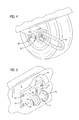
- FIG. 4 is a perspective view showing a rope shackle secured within the hitch receiver of a vehicle with an attachment thimble that embodies the invention.
- FIG. 5 is a perspective view of another embodiment of a rope shackle attachment thimble attached to the D-ring mounts on the bumper of a vehicle.
- FIG. 1 shows a rope shackle attachment thimble 11 according to one embodiment of the invention.
- the thimble 11 has a first flange 12 on one end and a second flange 13 on the opposite end. The outside faces of the flanges are generally flat.
- a drum portion 14 of the thimble extends between the first and second flanges 12 and 13 .
- the drum portion 14 tapers inwardly from each flange as indicated at 16 to a smaller diameter mid-portion between the flanges.
- the diameter of the mid-portion is sufficiently smaller than the dimensions of the flanges to allow a rope to extend around the mid-portion and not project outwardly beyond the outer edges of the flanges.
- a through-bore 17 is formed through the thimble 11 and extends from the first flange 12 , through the mid-portion 14 , and through the second flange 13 as shown.
- the through-bore has a diameter that is sufficient to receive a securement pin as described in more detail below.
- FIG. 2 shows the thimble 11 being used to anchor a rope shackle to the trailer hitch receiver 22 of a vehicle.
- the rope shackle 15 is made of a length of rope 18 having an eyelet 19 formed at one end and a knot formed at the opposite end.
- the knot 21 can be pressed through the eyelet 19 to form the length of rope 18 into a loop.
- Items such as recovery ropes, chains, or cables can then be attached to the looped rope shackle for use in pulling or other tasks.
- the rope shackle 15 has been formed into a loop and the attachment thimble 11 of this invention has been inserted into the loop.
- the knot 21 , eyelet 19 , and the thimble 11 are them moved into the opening 26 of the hitch receiver 22 as indicated by arrow 20 .
- the thimble 11 is sized so that it fits within the opening 26 of the hitch receiver and slides therein with ease.
- the knot 21 and eyelet 19 are slid into the receiver ahead of the thimble 11 and all are moved into the receiver until the through-bore 12 in the thimble aligns with the holes 24 in each side wall of the receiver.
- a securement pin 23 is inserted through one hole 24 , through the through-bore 17 , and through the aligned opposite hole 24 (not visible in FIG. 2 ) in the other side wall of the receiver.
- a spring pin can then be inserted through a hole 27 in the protruding end of the securement pin 23 to lock the securement pin securely in place.
- the rope shackle 15 is securely held within the hitch receiver by the thimble. Further, the confined space in the receiver behind the thimble ensures that the knot 21 cannot slip out of the eyelet 19 when the rope shackle is under strain.
- the looped end of the rope shackle projects rearwardly from the hitch receiver where it is available to be attached to recovery ropes or other items.
- FIG. 3 illustrates a typical rope shackle formed into a loop and extending around an attachment thimble according to the invention.
- the rope shackle 15 is formed from a length of rope 18 (which is covered with a protective sheath in this figure) with an eyelet 19 formed at one end and a knot formed at the other end.
- the knot 21 is pressed through the eyelet 19 and the rope 18 is pulled tight to lock the knot behind the eyelet.
- the rope 18 extends from the knot 21 and eyelet 19 around the mid-portion of attachment thimble 11 .
- the diameter of the mid-portion is small enough to allow the rope to extend around the mid-portion of the thimble without projecting beyond the outer edges of the flanges of the thimble 11 .
- the knot 21 , eyelet 19 , and attachment thimble 11 can all be slid together into a hitch receiver and secured as described above.
- FIG. 4 shows a rope shackle after having been secured in a hitch receiver.
- the looped end of the rope 18 is seen projecting from the opening of the hitch receiver for attachment to a rope, cable, chain, or other item.
- the attachment thimble 11 can be seen recessed into the hitch receiver.
- a securement pin 23 has been inserted through the hitch receiver and attachment thimble and has been secured with a pin 26 .
- the rope shackle is thereby locked securely in the hitch receiver.
- the securement pin 23 is removed and the shackle and attachment thimble is pulled out of the hitch receiver.
- the recess between the end of the hitch receiver and the attachment thimble can be sufficiently deep to allow the looped end of the rope shackle to be wadded up and stowed within the recess until needed.
- FIG. 4 shows an alternate embodiment of an attachment thimble for use with a D-ring mounting structure on a bumper of a vehicle.
- the bumper 31 which may be a front bumper or a rear bumper, has secured thereon a mounting structure 32 commonly used to mount a metal D-ring.
- the mounting structure 32 is secured with bolts that extend through bolt holes 34 in the base 33 of the structure, but it might also be welded or otherwise attached to the bumper.
- Spaced apart mounting dogs 36 and 37 extend away from the base 33 and each has a hole extending therethrough. The holes are aligned with each other.
- a metal D-ring is mounted to the mounting dogs with a threaded pin as is known in the art.
- an attachment thimble 11 is disposed between the mounting dogs 36 and 37 .
- a securement pin 38 extends through the aligned holes in the mounting dogs and through the through-hole in the attachment thimble.
- the securement pin 38 is slightly smaller than the through-hole so that the thimble is able to rotate while attached, as indicated by arrow 39 .
- a rope shackle can be attached to the assembly by threading one end of the length of rope around the back of the thimble as indicated by arrow 41 . The rope shackle can then be formed into a loop and its knot pressed through its eyelet to secure the rope shackle in place. The rope shackle is then available for use in towing or other tasks.
- the attachment thimble of this invention can be made of any appropriate material such as steel, carbon fiber, or plastic.
- the preferable material is aluminum because of its light weight, strength, cost, and durability.
Landscapes
- Engineering & Computer Science (AREA)
- Mechanical Engineering (AREA)
- General Engineering & Computer Science (AREA)
- Transportation (AREA)
- Hooks, Suction Cups, And Attachment By Adhesive Means (AREA)
Abstract
Description
Claims (20)
Priority Applications (4)
| Application Number | Priority Date | Filing Date | Title |
|---|---|---|---|
| US15/798,000 US10434829B2 (en) | 2017-10-30 | 2017-10-30 | Rope shackle attachment thimble |
| US29/634,406 USD831470S1 (en) | 2017-10-30 | 2018-01-22 | Rope shackle attachment thimble |
| CA3020408A CA3020408C (en) | 2017-10-30 | 2018-10-11 | Rope shackle attachment thimble |
| DE102018126667.7A DE102018126667B4 (en) | 2017-10-30 | 2018-10-25 | Method of attaching a rope shackle and rope shackle assembly |
Applications Claiming Priority (1)
| Application Number | Priority Date | Filing Date | Title |
|---|---|---|---|
| US15/798,000 US10434829B2 (en) | 2017-10-30 | 2017-10-30 | Rope shackle attachment thimble |
Related Child Applications (1)
| Application Number | Title | Priority Date | Filing Date |
|---|---|---|---|
| US29/634,406 Continuation USD831470S1 (en) | 2017-10-30 | 2018-01-22 | Rope shackle attachment thimble |
Publications (2)
| Publication Number | Publication Date |
|---|---|
| US20190126698A1 US20190126698A1 (en) | 2019-05-02 |
| US10434829B2 true US10434829B2 (en) | 2019-10-08 |
Family
ID=63832878
Family Applications (2)
| Application Number | Title | Priority Date | Filing Date |
|---|---|---|---|
| US15/798,000 Active 2038-02-07 US10434829B2 (en) | 2017-10-30 | 2017-10-30 | Rope shackle attachment thimble |
| US29/634,406 Active USD831470S1 (en) | 2017-10-30 | 2018-01-22 | Rope shackle attachment thimble |
Family Applications After (1)
| Application Number | Title | Priority Date | Filing Date |
|---|---|---|---|
| US29/634,406 Active USD831470S1 (en) | 2017-10-30 | 2018-01-22 | Rope shackle attachment thimble |
Country Status (3)
| Country | Link |
|---|---|
| US (2) | US10434829B2 (en) |
| CA (1) | CA3020408C (en) |
| DE (1) | DE102018126667B4 (en) |
Cited By (1)
| Publication number | Priority date | Publication date | Assignee | Title |
|---|---|---|---|---|
| US11326667B2 (en) | 2020-01-10 | 2022-05-10 | Fusion Tools, Inc. | Lockable shackle apparatus and method of use |
Families Citing this family (4)
| Publication number | Priority date | Publication date | Assignee | Title |
|---|---|---|---|---|
| USD867859S1 (en) * | 2018-08-22 | 2019-11-26 | Glenda Herbert | Cord management device |
| USD880487S1 (en) * | 2018-09-28 | 2020-04-07 | Purple Tambourine Limited | Pointing controller |
| JP1656621S (en) * | 2019-08-27 | 2020-04-06 | ||
| USD928670S1 (en) * | 2020-08-20 | 2021-08-24 | Beichuan QiangJia Technology Co., Ltd. | Tow rope |
Citations (18)
| Publication number | Priority date | Publication date | Assignee | Title |
|---|---|---|---|---|
| US2561371A (en) | 1949-01-24 | 1951-07-24 | Hill James Miles | Airplane mooring rope shackle |
| US2877621A (en) * | 1955-03-21 | 1959-03-17 | William K Robbins | Three piece separable section chain connector and the like |
| US4145874A (en) * | 1976-05-22 | 1979-03-27 | Eisen- Und Drahtwerk Erlau Aktiengesellschaft | Shackle for chains, especially for sling chains |
| US5046881A (en) * | 1991-02-01 | 1991-09-10 | Swager William E | Lockable pin and clevis |
| US5647198A (en) * | 1995-06-12 | 1997-07-15 | Wichard | Rigging component of "thimble-shackle" type |
| US6023927A (en) * | 1998-06-25 | 2000-02-15 | Epstein; Irving | Shackle with a kant loose pin |
| US6158760A (en) | 1999-01-22 | 2000-12-12 | Tow Hook Concepts, Llc | Trailer hitch assembly |
| US6698256B2 (en) * | 2002-03-11 | 2004-03-02 | Bryan Witchey | Ball and ring hitch lock |
| US20040194259A1 (en) | 2003-01-13 | 2004-10-07 | Tylaska Timothy T | Mechanical knot apparatus |
| US7871097B2 (en) * | 2004-01-21 | 2011-01-18 | Vernon W. Sparkes | Pivoting hitch assembly |
| USD657234S1 (en) * | 2010-12-07 | 2012-04-10 | Herman Edward J | Soft shackle |
| US8205922B1 (en) | 2011-04-07 | 2012-06-26 | The Crosby Group LLC | Grommet shackle |
| US20120280523A1 (en) | 2011-05-05 | 2012-11-08 | Michael Douglas Costa | Shackle or clevis mount fitting for steel cable and synthetic rope end loops |
| US8322003B2 (en) | 2009-04-22 | 2012-12-04 | Zedel | Attachment shackle with lockable rotating ferrule |
| US8328223B2 (en) | 2010-10-13 | 2012-12-11 | Leinenger Bradley R | Attachment assembly for a vehicle |
| US9726255B1 (en) * | 2016-04-25 | 2017-08-08 | Patrick M Tarrant | Shackle with self centering closure cross member |
| US20170334533A1 (en) * | 2014-11-07 | 2017-11-23 | Edward J. Herman | Soft shackle and method of making |
| USD826036S1 (en) * | 2016-09-21 | 2018-08-21 | Bubba Rope, LLC | Three-tone rope shackle |
Family Cites Families (15)
| Publication number | Priority date | Publication date | Assignee | Title |
|---|---|---|---|---|
| US2709616A (en) * | 1952-09-15 | 1955-05-31 | Larson Victor Sjunne | Thimble ring for shackles |
| CH597010A5 (en) | 1974-03-13 | 1978-03-31 | Lucien Masson | Safety loop for securing tow rope |
| US4164378A (en) | 1977-09-02 | 1979-08-14 | Samson Ocean Systems, Inc. | Rope fitting |
| US4842219A (en) | 1987-10-30 | 1989-06-27 | Westinghouse Electric Corp. | Tether attachment device |
| US7306253B2 (en) | 2005-08-24 | 2007-12-11 | Martin J. Markley | Automotive coupling device |
| US8602370B2 (en) * | 2011-04-27 | 2013-12-10 | Martha McKenzie | Hanger holder accessory and system |
| US8966717B2 (en) * | 2011-06-14 | 2015-03-03 | Chin-Fu Chen | Safety cord connector for window blind |
| USD679581S1 (en) * | 2011-11-17 | 2013-04-09 | Cheng Uei Precision Industry Co., Ltd. | Cable clip |
| USD698229S1 (en) * | 2013-03-15 | 2014-01-28 | Stout Stuff, Llc | Cable crimp cover |
| USD708052S1 (en) * | 2014-01-07 | 2014-07-01 | Bluelounge Pte. Ltd. | Cable management end clip |
| US10056766B2 (en) * | 2014-01-07 | 2018-08-21 | Limitless Innovations, Inc. | System for charging multiple devices |
| US20150330478A1 (en) * | 2014-05-14 | 2015-11-19 | Beats Electronics, Llc | Cable management member |
| USD763060S1 (en) * | 2014-12-10 | 2016-08-09 | European Trailer Systems Gmbh | Joint for sliding roofs for trucks |
| USD752955S1 (en) * | 2015-01-13 | 2016-04-05 | Griffin Technology, Inc. | Cord holder |
| USD1006078S1 (en) * | 2021-11-10 | 2023-11-28 | Korloy Inc. | Cutting insert for machine tools for metalworking |
-
2017
- 2017-10-30 US US15/798,000 patent/US10434829B2/en active Active
-
2018
- 2018-01-22 US US29/634,406 patent/USD831470S1/en active Active
- 2018-10-11 CA CA3020408A patent/CA3020408C/en active Active
- 2018-10-25 DE DE102018126667.7A patent/DE102018126667B4/en active Active
Patent Citations (20)
| Publication number | Priority date | Publication date | Assignee | Title |
|---|---|---|---|---|
| US2561371A (en) | 1949-01-24 | 1951-07-24 | Hill James Miles | Airplane mooring rope shackle |
| US2877621A (en) * | 1955-03-21 | 1959-03-17 | William K Robbins | Three piece separable section chain connector and the like |
| US4145874A (en) * | 1976-05-22 | 1979-03-27 | Eisen- Und Drahtwerk Erlau Aktiengesellschaft | Shackle for chains, especially for sling chains |
| US5046881A (en) * | 1991-02-01 | 1991-09-10 | Swager William E | Lockable pin and clevis |
| US5647198A (en) * | 1995-06-12 | 1997-07-15 | Wichard | Rigging component of "thimble-shackle" type |
| US6023927A (en) * | 1998-06-25 | 2000-02-15 | Epstein; Irving | Shackle with a kant loose pin |
| US6158760A (en) | 1999-01-22 | 2000-12-12 | Tow Hook Concepts, Llc | Trailer hitch assembly |
| US6698256B2 (en) * | 2002-03-11 | 2004-03-02 | Bryan Witchey | Ball and ring hitch lock |
| US20040194259A1 (en) | 2003-01-13 | 2004-10-07 | Tylaska Timothy T | Mechanical knot apparatus |
| US8641076B2 (en) * | 2004-01-21 | 2014-02-04 | Vernon W. Sparkes | Pivoting hitch assembly |
| US7871097B2 (en) * | 2004-01-21 | 2011-01-18 | Vernon W. Sparkes | Pivoting hitch assembly |
| US8322003B2 (en) | 2009-04-22 | 2012-12-04 | Zedel | Attachment shackle with lockable rotating ferrule |
| US8328223B2 (en) | 2010-10-13 | 2012-12-11 | Leinenger Bradley R | Attachment assembly for a vehicle |
| USD657234S1 (en) * | 2010-12-07 | 2012-04-10 | Herman Edward J | Soft shackle |
| US8205922B1 (en) | 2011-04-07 | 2012-06-26 | The Crosby Group LLC | Grommet shackle |
| US20120280523A1 (en) | 2011-05-05 | 2012-11-08 | Michael Douglas Costa | Shackle or clevis mount fitting for steel cable and synthetic rope end loops |
| US9388025B2 (en) * | 2011-05-05 | 2016-07-12 | Factor 55, Llc | Shackle or clevis mount fitting for steel cable and synthetic rope end loops |
| US20170334533A1 (en) * | 2014-11-07 | 2017-11-23 | Edward J. Herman | Soft shackle and method of making |
| US9726255B1 (en) * | 2016-04-25 | 2017-08-08 | Patrick M Tarrant | Shackle with self centering closure cross member |
| USD826036S1 (en) * | 2016-09-21 | 2018-08-21 | Bubba Rope, LLC | Three-tone rope shackle |
Non-Patent Citations (1)
| Title |
|---|
| Photographs 1-4. |
Cited By (1)
| Publication number | Priority date | Publication date | Assignee | Title |
|---|---|---|---|---|
| US11326667B2 (en) | 2020-01-10 | 2022-05-10 | Fusion Tools, Inc. | Lockable shackle apparatus and method of use |
Also Published As
| Publication number | Publication date |
|---|---|
| DE102018126667A1 (en) | 2019-05-02 |
| US20190126698A1 (en) | 2019-05-02 |
| USD831470S1 (en) | 2018-10-23 |
| CA3020408C (en) | 2020-08-18 |
| CA3020408A1 (en) | 2019-04-30 |
| DE102018126667B4 (en) | 2023-01-05 |
Similar Documents
| Publication | Publication Date | Title |
|---|---|---|
| US10434829B2 (en) | Rope shackle attachment thimble | |
| AU2016101941A4 (en) | Shackle or clevis mount fitting for steel cable and synthetic rope end loops | |
| CA2907828C (en) | Tow adapter | |
| US9890831B1 (en) | Shackle safety pin | |
| US7076845B2 (en) | Mechanical knot apparatus | |
| US8960707B2 (en) | Pivoting tow hook | |
| US3740079A (en) | Vehicular towing hitch | |
| US9744820B1 (en) | Vehicle recovery hitch attachment device | |
| US4635953A (en) | Tow cable with bracket and storage means | |
| US7823942B1 (en) | Towing accessory | |
| CA2896948C (en) | Attachment system for attaching an external component to a chassis of a vehicle | |
| US6467792B2 (en) | Trailer hitch assembly with integral tow hooks | |
| US20190338830A1 (en) | Single piece quick connect and disconnect chassis systems | |
| US6644679B1 (en) | Towing attachment and method | |
| US20120023710A1 (en) | Trailer Hitch-Ball Chain Coupler | |
| CN207434358U (en) | General equipment transports binding reinforcing device | |
| US20130334792A1 (en) | Device for securing a hitch sleeve to a hitch | |
| US20230415633A1 (en) | Method for Securing Cargo Boxes Upon the Bed of a Pickup Truck Device for Securing Cargo Boxes Upon the Bed of a Pickup Truck | |
| US20230137753A1 (en) | Method for Securing Cargo Boxes Upon the Bed of a Pick-up Truck; Device for Securing Cargo Boxes Upon the Bed of a Pick-up Truck | |
| US11300247B1 (en) | Size-adjustable hanging tie down device and method of securing objects | |
| GB2377685A (en) | Vehicle-towing rope structure with fluorescent and anti-slip properties | |
| GB2394704A (en) | Security device for use with trailer | |
| GB2473738A (en) | Towbar with connection for eyelet of towed vehicle |
Legal Events
| Date | Code | Title | Description |
|---|---|---|---|
| FEPP | Fee payment procedure |
Free format text: ENTITY STATUS SET TO UNDISCOUNTED (ORIGINAL EVENT CODE: BIG.); ENTITY STATUS OF PATENT OWNER: LARGE ENTITY |
|
| FEPP | Fee payment procedure |
Free format text: ENTITY STATUS SET TO SMALL (ORIGINAL EVENT CODE: SMAL); ENTITY STATUS OF PATENT OWNER: LARGE ENTITY |
|
| AS | Assignment |
Owner name: OMIX-ADA, INC., GEORGIA Free format text: ASSIGNMENT OF ASSIGNORS INTEREST;ASSIGNORS:RUSSELL, ERIC;BENNETT, PATRICK W.;SIGNING DATES FROM 20171128 TO 20171205;REEL/FRAME:044461/0135 |
|
| STPP | Information on status: patent application and granting procedure in general |
Free format text: RESPONSE TO NON-FINAL OFFICE ACTION ENTERED AND FORWARDED TO EXAMINER |
|
| AS | Assignment |
Owner name: WILMINGTON TRUST, NATIONAL ASSOCIATION, AS COLLATE Free format text: PATENT SECURITY AGREEMENT (INDENTURE);ASSIGNOR:OMIX-ADA, INC.;REEL/FRAME:049677/0724 Effective date: 20190510 Owner name: WILMINGTON TRUST, NATIONAL ASSOCIATION, AS COLLATE Free format text: PATENT SECURITY AGREEMENT (INDENTURE);ASSIGNOR:HUSKY LINERS, INC.;REEL/FRAME:049677/0706 Effective date: 20190510 Owner name: JEFFERIES FINANCE LLC, ADMINISTRATIVE AGENT, NEW Y Free format text: FIRST LIEN PATENT SECURITY AGREEMENT SUPPLEMENT;ASSIGNOR:OMIX-ADA, INC.;REEL/FRAME:049678/0762 Effective date: 20190607 Owner name: JEFFERIES FINANCE LLC, ADMINISTRATIVE AGENT, NEW Y Free format text: SECOND LIEN PATENT SECURITY AGREEMENT SUPPLEMENT;ASSIGNOR:OMIX-ADA, INC.;REEL/FRAME:049678/0788 Effective date: 20190607 Owner name: JEFFERIES FINANCE LLC, ADMINISTRATIVE AGENT, NEW YORK Free format text: SECOND LIEN PATENT SECURITY AGREEMENT SUPPLEMENT;ASSIGNOR:OMIX-ADA, INC.;REEL/FRAME:049678/0788 Effective date: 20190607 Owner name: JEFFERIES FINANCE LLC, ADMINISTRATIVE AGENT, NEW YORK Free format text: FIRST LIEN PATENT SECURITY AGREEMENT SUPPLEMENT;ASSIGNOR:OMIX-ADA, INC.;REEL/FRAME:049678/0762 Effective date: 20190607 Owner name: WILMINGTON TRUST, NATIONAL ASSOCIATION, AS COLLATERAL AGENT, MINNESOTA Free format text: PATENT SECURITY AGREEMENT (INDENTURE);ASSIGNOR:OMIX-ADA, INC.;REEL/FRAME:049677/0724 Effective date: 20190510 |
|
| STPP | Information on status: patent application and granting procedure in general |
Free format text: NOTICE OF ALLOWANCE MAILED -- APPLICATION RECEIVED IN OFFICE OF PUBLICATIONS |
|
| FEPP | Fee payment procedure |
Free format text: ENTITY STATUS SET TO UNDISCOUNTED (ORIGINAL EVENT CODE: BIG.); ENTITY STATUS OF PATENT OWNER: LARGE ENTITY |
|
| STPP | Information on status: patent application and granting procedure in general |
Free format text: PUBLICATIONS -- ISSUE FEE PAYMENT VERIFIED |
|
| STCF | Information on status: patent grant |
Free format text: PATENTED CASE |
|
| AS | Assignment |
Owner name: BANK OF AMERICA, N.A., AS COLLATERAL AGENT, TEXAS Free format text: PATENT SECURITY AGREEMENT (ABL);ASSIGNOR:OMIX-ADA, INC.;REEL/FRAME:055176/0336 Effective date: 20210129 Owner name: JEFFERIES FINANCE LLC, AS COLLATERAL AGENT, NEW YORK Free format text: PATENT SECURITY AGREEMENT (TL);ASSIGNOR:OMIX-ADA, INC.;REEL/FRAME:055175/0153 Effective date: 20210129 |
|
| AS | Assignment |
Owner name: OMIX-ADA, INC., GEORGIA Free format text: RELEASE OF SECOND LIEN SECURITY INTEREST IN PATENTS;ASSIGNOR:JEFFERIES FINANCE LLC, AS ADMINISTRATIVE AND COLLATERAL AGENT;REEL/FRAME:055190/0229 Effective date: 20210129 Owner name: OMIX-ADA, INC., GEORGIA Free format text: RELEASE OF FIRST LIEN SECURITY INTEREST IN PATENTS;ASSIGNOR:JEFFERIES FINANCE LLC, AS ADMINISTRATIVE AND COLLATERAL AGENT;REEL/FRAME:055190/0213 Effective date: 20210129 |
|
| AS | Assignment |
Owner name: UNDERCOVER, INC., MISSOURI Free format text: RELEASE BY SECURED PARTY;ASSIGNOR:WILMINGTON TRUST, NATIONAL ASSOCIATION, AS COLLATERAL AGENT;REEL/FRAME:055193/0892 Effective date: 20210129 Owner name: RETRAX HOLDINGS, LLC, NORTH DAKOTA Free format text: RELEASE BY SECURED PARTY;ASSIGNOR:WILMINGTON TRUST, NATIONAL ASSOCIATION, AS COLLATERAL AGENT;REEL/FRAME:055193/0892 Effective date: 20210129 Owner name: BEDRUG, INC., TENNESSEE Free format text: RELEASE BY SECURED PARTY;ASSIGNOR:WILMINGTON TRUST, NATIONAL ASSOCIATION, AS COLLATERAL AGENT;REEL/FRAME:055193/0892 Effective date: 20210129 Owner name: A.R.E. ACCESSORIES LLC, OHIO Free format text: RELEASE BY SECURED PARTY;ASSIGNOR:WILMINGTON TRUST, NATIONAL ASSOCIATION, AS COLLATERAL AGENT;REEL/FRAME:055193/0892 Effective date: 20210129 Owner name: EXTANG CORPORATION, MICHIGAN Free format text: RELEASE BY SECURED PARTY;ASSIGNOR:WILMINGTON TRUST, NATIONAL ASSOCIATION, AS COLLATERAL AGENT;REEL/FRAME:055193/0892 Effective date: 20210129 Owner name: LUND, INC., GEORGIA Free format text: RELEASE BY SECURED PARTY;ASSIGNOR:WILMINGTON TRUST, NATIONAL ASSOCIATION, AS COLLATERAL AGENT;REEL/FRAME:055193/0892 Effective date: 20210129 Owner name: RUGGED LINER, INC., MICHIGAN Free format text: RELEASE BY SECURED PARTY;ASSIGNOR:WILMINGTON TRUST, NATIONAL ASSOCIATION, AS COLLATERAL AGENT;REEL/FRAME:055193/0892 Effective date: 20210129 Owner name: TRUXEDO INC., SOUTH DAKOTA Free format text: RELEASE BY SECURED PARTY;ASSIGNOR:WILMINGTON TRUST, NATIONAL ASSOCIATION, AS COLLATERAL AGENT;REEL/FRAME:055193/0892 Effective date: 20210129 Owner name: LAURMARK ENTERPRISES, INC., MICHIGAN Free format text: RELEASE BY SECURED PARTY;ASSIGNOR:WILMINGTON TRUST, NATIONAL ASSOCIATION, AS COLLATERAL AGENT;REEL/FRAME:055193/0892 Effective date: 20210129 Owner name: OMIX-ADA, INC., GEORGIA Free format text: RELEASE BY SECURED PARTY;ASSIGNOR:WILMINGTON TRUST, NATIONAL ASSOCIATION, AS COLLATERAL AGENT;REEL/FRAME:055193/0892 Effective date: 20210129 Owner name: N-FAB, INC., TEXAS Free format text: RELEASE BY SECURED PARTY;ASSIGNOR:WILMINGTON TRUST, NATIONAL ASSOCIATION, AS COLLATERAL AGENT;REEL/FRAME:055193/0892 Effective date: 20210129 Owner name: ROLL-N-LOCK CORPORATION, GEORGIA Free format text: RELEASE BY SECURED PARTY;ASSIGNOR:WILMINGTON TRUST, NATIONAL ASSOCIATION, AS COLLATERAL AGENT;REEL/FRAME:055193/0892 Effective date: 20210129 Owner name: ADVANTAGE TRUCK ACCESSORIES INC., MICHIGAN Free format text: RELEASE BY SECURED PARTY;ASSIGNOR:WILMINGTON TRUST, NATIONAL ASSOCIATION, AS COLLATERAL AGENT;REEL/FRAME:055193/0892 Effective date: 20210129 Owner name: BUSHWACKER, INC., GEORGIA Free format text: RELEASE BY SECURED PARTY;ASSIGNOR:WILMINGTON TRUST, NATIONAL ASSOCIATION, AS COLLATERAL AGENT;REEL/FRAME:055193/0892 Effective date: 20210129 Owner name: LUND MOTION PRODUCTS, INC., GEORGIA Free format text: RELEASE BY SECURED PARTY;ASSIGNOR:WILMINGTON TRUST, NATIONAL ASSOCIATION, AS COLLATERAL AGENT;REEL/FRAME:055193/0892 Effective date: 20210129 Owner name: HUSKY LINERS, INC., KANSAS Free format text: RELEASE BY SECURED PARTY;ASSIGNOR:WILMINGTON TRUST, NATIONAL ASSOCIATION, AS COLLATERAL AGENT;REEL/FRAME:055193/0892 Effective date: 20210129 |
|
| MAFP | Maintenance fee payment |
Free format text: PAYMENT OF MAINTENANCE FEE, 4TH YEAR, LARGE ENTITY (ORIGINAL EVENT CODE: M1551); ENTITY STATUS OF PATENT OWNER: LARGE ENTITY Year of fee payment: 4 |