US10433972B2 - Adjustable implant - Google Patents
Adjustable implant Download PDFInfo
- Publication number
- US10433972B2 US10433972B2 US15/520,083 US201515520083A US10433972B2 US 10433972 B2 US10433972 B2 US 10433972B2 US 201515520083 A US201515520083 A US 201515520083A US 10433972 B2 US10433972 B2 US 10433972B2
- Authority
- US
- United States
- Prior art keywords
- implant
- length
- telescopic body
- segment
- end segment
- Prior art date
- Legal status (The legal status is an assumption and is not a legal conclusion. Google has not performed a legal analysis and makes no representation as to the accuracy of the status listed.)
- Active
Links
- 239000007943 implant Substances 0.000 title claims abstract description 128
- 230000000295 complement effect Effects 0.000 claims description 8
- 230000008859 change Effects 0.000 claims description 6
- 238000006073 displacement reaction Methods 0.000 claims description 4
- 230000007246 mechanism Effects 0.000 description 17
- 210000001519 tissue Anatomy 0.000 description 16
- 230000008901 benefit Effects 0.000 description 4
- 238000013459 approach Methods 0.000 description 3
- 230000005489 elastic deformation Effects 0.000 description 3
- 238000003780 insertion Methods 0.000 description 3
- 230000037431 insertion Effects 0.000 description 3
- 230000002146 bilateral effect Effects 0.000 description 2
- 230000000694 effects Effects 0.000 description 2
- 230000004927 fusion Effects 0.000 description 2
- 239000000463 material Substances 0.000 description 2
- 238000000034 method Methods 0.000 description 2
- 230000008569 process Effects 0.000 description 2
- 238000000926 separation method Methods 0.000 description 2
- 239000004696 Poly ether ether ketone Substances 0.000 description 1
- RTAQQCXQSZGOHL-UHFFFAOYSA-N Titanium Chemical compound [Ti] RTAQQCXQSZGOHL-UHFFFAOYSA-N 0.000 description 1
- 238000004873 anchoring Methods 0.000 description 1
- JUPQTSLXMOCDHR-UHFFFAOYSA-N benzene-1,4-diol;bis(4-fluorophenyl)methanone Chemical compound OC1=CC=C(O)C=C1.C1=CC(F)=CC=C1C(=O)C1=CC=C(F)C=C1 JUPQTSLXMOCDHR-UHFFFAOYSA-N 0.000 description 1
- 210000000988 bone and bone Anatomy 0.000 description 1
- 238000012937 correction Methods 0.000 description 1
- 230000007423 decrease Effects 0.000 description 1
- 230000001045 lordotic effect Effects 0.000 description 1
- 238000012986 modification Methods 0.000 description 1
- 230000004048 modification Effects 0.000 description 1
- 230000000399 orthopedic effect Effects 0.000 description 1
- 229920002530 polyetherether ketone Polymers 0.000 description 1
- 229920000642 polymer Polymers 0.000 description 1
- 230000007425 progressive decline Effects 0.000 description 1
- 230000000750 progressive effect Effects 0.000 description 1
- 230000002441 reversible effect Effects 0.000 description 1
- 238000004904 shortening Methods 0.000 description 1
- 238000001356 surgical procedure Methods 0.000 description 1
- 229910000811 surgical stainless steel Inorganic materials 0.000 description 1
- 239000010966 surgical stainless steel Substances 0.000 description 1
- 229910052719 titanium Inorganic materials 0.000 description 1
- 239000010936 titanium Substances 0.000 description 1
Images


Classifications
-
- A—HUMAN NECESSITIES
- A61—MEDICAL OR VETERINARY SCIENCE; HYGIENE
- A61F—FILTERS IMPLANTABLE INTO BLOOD VESSELS; PROSTHESES; DEVICES PROVIDING PATENCY TO, OR PREVENTING COLLAPSING OF, TUBULAR STRUCTURES OF THE BODY, e.g. STENTS; ORTHOPAEDIC, NURSING OR CONTRACEPTIVE DEVICES; FOMENTATION; TREATMENT OR PROTECTION OF EYES OR EARS; BANDAGES, DRESSINGS OR ABSORBENT PADS; FIRST-AID KITS
- A61F2/00—Filters implantable into blood vessels; Prostheses, i.e. artificial substitutes or replacements for parts of the body; Appliances for connecting them with the body; Devices providing patency to, or preventing collapsing of, tubular structures of the body, e.g. stents
- A61F2/02—Prostheses implantable into the body
- A61F2/30—Joints
- A61F2/44—Joints for the spine, e.g. vertebrae, spinal discs
- A61F2/442—Intervertebral or spinal discs, e.g. resilient
-
- A—HUMAN NECESSITIES
- A61—MEDICAL OR VETERINARY SCIENCE; HYGIENE
- A61B—DIAGNOSIS; SURGERY; IDENTIFICATION
- A61B17/00—Surgical instruments, devices or methods, e.g. tourniquets
- A61B17/56—Surgical instruments or methods for treatment of bones or joints; Devices specially adapted therefor
- A61B17/58—Surgical instruments or methods for treatment of bones or joints; Devices specially adapted therefor for osteosynthesis, e.g. bone plates, screws, setting implements or the like
- A61B17/88—Osteosynthesis instruments; Methods or means for implanting or extracting internal or external fixation devices
- A61B17/885—Tools for expanding or compacting bones or discs or cavities therein
- A61B17/8852—Tools for expanding or compacting bones or discs or cavities therein capable of being assembled or enlarged, or changing shape, inside the bone or disc
- A61B17/8858—Tools for expanding or compacting bones or discs or cavities therein capable of being assembled or enlarged, or changing shape, inside the bone or disc laterally or radially expansible
-
- A—HUMAN NECESSITIES
- A61—MEDICAL OR VETERINARY SCIENCE; HYGIENE
- A61F—FILTERS IMPLANTABLE INTO BLOOD VESSELS; PROSTHESES; DEVICES PROVIDING PATENCY TO, OR PREVENTING COLLAPSING OF, TUBULAR STRUCTURES OF THE BODY, e.g. STENTS; ORTHOPAEDIC, NURSING OR CONTRACEPTIVE DEVICES; FOMENTATION; TREATMENT OR PROTECTION OF EYES OR EARS; BANDAGES, DRESSINGS OR ABSORBENT PADS; FIRST-AID KITS
- A61F2/00—Filters implantable into blood vessels; Prostheses, i.e. artificial substitutes or replacements for parts of the body; Appliances for connecting them with the body; Devices providing patency to, or preventing collapsing of, tubular structures of the body, e.g. stents
- A61F2/02—Prostheses implantable into the body
- A61F2/30—Joints
- A61F2/44—Joints for the spine, e.g. vertebrae, spinal discs
- A61F2/4455—Joints for the spine, e.g. vertebrae, spinal discs for the fusion of spinal bodies, e.g. intervertebral fusion of adjacent spinal bodies, e.g. fusion cages
- A61F2/447—Joints for the spine, e.g. vertebrae, spinal discs for the fusion of spinal bodies, e.g. intervertebral fusion of adjacent spinal bodies, e.g. fusion cages substantially parallelepipedal, e.g. having a rectangular or trapezoidal cross-section
-
- A—HUMAN NECESSITIES
- A61—MEDICAL OR VETERINARY SCIENCE; HYGIENE
- A61B—DIAGNOSIS; SURGERY; IDENTIFICATION
- A61B17/00—Surgical instruments, devices or methods, e.g. tourniquets
- A61B17/56—Surgical instruments or methods for treatment of bones or joints; Devices specially adapted therefor
-
- A—HUMAN NECESSITIES
- A61—MEDICAL OR VETERINARY SCIENCE; HYGIENE
- A61F—FILTERS IMPLANTABLE INTO BLOOD VESSELS; PROSTHESES; DEVICES PROVIDING PATENCY TO, OR PREVENTING COLLAPSING OF, TUBULAR STRUCTURES OF THE BODY, e.g. STENTS; ORTHOPAEDIC, NURSING OR CONTRACEPTIVE DEVICES; FOMENTATION; TREATMENT OR PROTECTION OF EYES OR EARS; BANDAGES, DRESSINGS OR ABSORBENT PADS; FIRST-AID KITS
- A61F2/00—Filters implantable into blood vessels; Prostheses, i.e. artificial substitutes or replacements for parts of the body; Appliances for connecting them with the body; Devices providing patency to, or preventing collapsing of, tubular structures of the body, e.g. stents
- A61F2/02—Prostheses implantable into the body
- A61F2/30—Joints
- A61F2/46—Special tools or methods for implanting or extracting artificial joints, accessories, bone grafts or substitutes, or particular adaptations therefor
- A61F2/4603—Special tools or methods for implanting or extracting artificial joints, accessories, bone grafts or substitutes, or particular adaptations therefor for insertion or extraction of endoprosthetic joints or of accessories thereof
- A61F2/4611—Special tools or methods for implanting or extracting artificial joints, accessories, bone grafts or substitutes, or particular adaptations therefor for insertion or extraction of endoprosthetic joints or of accessories thereof of spinal prostheses
-
- A—HUMAN NECESSITIES
- A61—MEDICAL OR VETERINARY SCIENCE; HYGIENE
- A61F—FILTERS IMPLANTABLE INTO BLOOD VESSELS; PROSTHESES; DEVICES PROVIDING PATENCY TO, OR PREVENTING COLLAPSING OF, TUBULAR STRUCTURES OF THE BODY, e.g. STENTS; ORTHOPAEDIC, NURSING OR CONTRACEPTIVE DEVICES; FOMENTATION; TREATMENT OR PROTECTION OF EYES OR EARS; BANDAGES, DRESSINGS OR ABSORBENT PADS; FIRST-AID KITS
- A61F2/00—Filters implantable into blood vessels; Prostheses, i.e. artificial substitutes or replacements for parts of the body; Appliances for connecting them with the body; Devices providing patency to, or preventing collapsing of, tubular structures of the body, e.g. stents
- A61F2/02—Prostheses implantable into the body
- A61F2/30—Joints
- A61F2002/30001—Additional features of subject-matter classified in A61F2/28, A61F2/30 and subgroups thereof
- A61F2002/30316—The prosthesis having different structural features at different locations within the same prosthesis; Connections between prosthetic parts; Special structural features of bone or joint prostheses not otherwise provided for
- A61F2002/30329—Connections or couplings between prosthetic parts, e.g. between modular parts; Connecting elements
- A61F2002/30405—Connections or couplings between prosthetic parts, e.g. between modular parts; Connecting elements made by screwing complementary threads machined on the parts themselves
-
- A—HUMAN NECESSITIES
- A61—MEDICAL OR VETERINARY SCIENCE; HYGIENE
- A61F—FILTERS IMPLANTABLE INTO BLOOD VESSELS; PROSTHESES; DEVICES PROVIDING PATENCY TO, OR PREVENTING COLLAPSING OF, TUBULAR STRUCTURES OF THE BODY, e.g. STENTS; ORTHOPAEDIC, NURSING OR CONTRACEPTIVE DEVICES; FOMENTATION; TREATMENT OR PROTECTION OF EYES OR EARS; BANDAGES, DRESSINGS OR ABSORBENT PADS; FIRST-AID KITS
- A61F2/00—Filters implantable into blood vessels; Prostheses, i.e. artificial substitutes or replacements for parts of the body; Appliances for connecting them with the body; Devices providing patency to, or preventing collapsing of, tubular structures of the body, e.g. stents
- A61F2/02—Prostheses implantable into the body
- A61F2/30—Joints
- A61F2002/30001—Additional features of subject-matter classified in A61F2/28, A61F2/30 and subgroups thereof
- A61F2002/30316—The prosthesis having different structural features at different locations within the same prosthesis; Connections between prosthetic parts; Special structural features of bone or joint prostheses not otherwise provided for
- A61F2002/30329—Connections or couplings between prosthetic parts, e.g. between modular parts; Connecting elements
- A61F2002/30471—Connections or couplings between prosthetic parts, e.g. between modular parts; Connecting elements connected by a hinged linkage mechanism, e.g. of the single-bar or multi-bar linkage type
-
- A—HUMAN NECESSITIES
- A61—MEDICAL OR VETERINARY SCIENCE; HYGIENE
- A61F—FILTERS IMPLANTABLE INTO BLOOD VESSELS; PROSTHESES; DEVICES PROVIDING PATENCY TO, OR PREVENTING COLLAPSING OF, TUBULAR STRUCTURES OF THE BODY, e.g. STENTS; ORTHOPAEDIC, NURSING OR CONTRACEPTIVE DEVICES; FOMENTATION; TREATMENT OR PROTECTION OF EYES OR EARS; BANDAGES, DRESSINGS OR ABSORBENT PADS; FIRST-AID KITS
- A61F2/00—Filters implantable into blood vessels; Prostheses, i.e. artificial substitutes or replacements for parts of the body; Appliances for connecting them with the body; Devices providing patency to, or preventing collapsing of, tubular structures of the body, e.g. stents
- A61F2/02—Prostheses implantable into the body
- A61F2/30—Joints
- A61F2002/30001—Additional features of subject-matter classified in A61F2/28, A61F2/30 and subgroups thereof
- A61F2002/30316—The prosthesis having different structural features at different locations within the same prosthesis; Connections between prosthetic parts; Special structural features of bone or joint prostheses not otherwise provided for
- A61F2002/30329—Connections or couplings between prosthetic parts, e.g. between modular parts; Connecting elements
- A61F2002/30476—Connections or couplings between prosthetic parts, e.g. between modular parts; Connecting elements locked by an additional locking mechanism
- A61F2002/30507—Connections or couplings between prosthetic parts, e.g. between modular parts; Connecting elements locked by an additional locking mechanism using a threaded locking member, e.g. a locking screw or a set screw
-
- A—HUMAN NECESSITIES
- A61—MEDICAL OR VETERINARY SCIENCE; HYGIENE
- A61F—FILTERS IMPLANTABLE INTO BLOOD VESSELS; PROSTHESES; DEVICES PROVIDING PATENCY TO, OR PREVENTING COLLAPSING OF, TUBULAR STRUCTURES OF THE BODY, e.g. STENTS; ORTHOPAEDIC, NURSING OR CONTRACEPTIVE DEVICES; FOMENTATION; TREATMENT OR PROTECTION OF EYES OR EARS; BANDAGES, DRESSINGS OR ABSORBENT PADS; FIRST-AID KITS
- A61F2/00—Filters implantable into blood vessels; Prostheses, i.e. artificial substitutes or replacements for parts of the body; Appliances for connecting them with the body; Devices providing patency to, or preventing collapsing of, tubular structures of the body, e.g. stents
- A61F2/02—Prostheses implantable into the body
- A61F2/30—Joints
- A61F2002/30001—Additional features of subject-matter classified in A61F2/28, A61F2/30 and subgroups thereof
- A61F2002/30316—The prosthesis having different structural features at different locations within the same prosthesis; Connections between prosthetic parts; Special structural features of bone or joint prostheses not otherwise provided for
- A61F2002/30535—Special structural features of bone or joint prostheses not otherwise provided for
- A61F2002/30537—Special structural features of bone or joint prostheses not otherwise provided for adjustable
- A61F2002/30538—Special structural features of bone or joint prostheses not otherwise provided for adjustable for adjusting angular orientation
-
- A—HUMAN NECESSITIES
- A61—MEDICAL OR VETERINARY SCIENCE; HYGIENE
- A61F—FILTERS IMPLANTABLE INTO BLOOD VESSELS; PROSTHESES; DEVICES PROVIDING PATENCY TO, OR PREVENTING COLLAPSING OF, TUBULAR STRUCTURES OF THE BODY, e.g. STENTS; ORTHOPAEDIC, NURSING OR CONTRACEPTIVE DEVICES; FOMENTATION; TREATMENT OR PROTECTION OF EYES OR EARS; BANDAGES, DRESSINGS OR ABSORBENT PADS; FIRST-AID KITS
- A61F2/00—Filters implantable into blood vessels; Prostheses, i.e. artificial substitutes or replacements for parts of the body; Appliances for connecting them with the body; Devices providing patency to, or preventing collapsing of, tubular structures of the body, e.g. stents
- A61F2/02—Prostheses implantable into the body
- A61F2/30—Joints
- A61F2002/30001—Additional features of subject-matter classified in A61F2/28, A61F2/30 and subgroups thereof
- A61F2002/30316—The prosthesis having different structural features at different locations within the same prosthesis; Connections between prosthetic parts; Special structural features of bone or joint prostheses not otherwise provided for
- A61F2002/30535—Special structural features of bone or joint prostheses not otherwise provided for
- A61F2002/30537—Special structural features of bone or joint prostheses not otherwise provided for adjustable
- A61F2002/30556—Special structural features of bone or joint prostheses not otherwise provided for adjustable for adjusting thickness
Definitions
- the present invention relates to surgical implants and, in particular, it concerns an adjustable implant including a telescopic body.
- the present invention relates primarily, although not exclusively, to a subset of such devices in which the implant includes a telescopic body, i.e., where a body includes first and second portions which undergo relative motion towards and/or away from each other so that a length of the telescopic body can be varied.
- the present invention is an adjustable implant.
- an adjustable implant comprising: (a) a telescopic body comprising a first portion and a second portion, the first and second portions being in sliding engagement such that a length of the telescopic body is adjustable from a first length to a second length; and (b) a deflectable linkage comprising a first linking segment, an intermediate segment pivotally connected to the first linking segment about a first pivot axis, and a second linking segment pivotally connected to the intermediate segment about a second pivot axis, the first linking segment being pivotally connected to the first portion and the second linking segment being pivotally connected to the second portion such that adjustment of a length of the telescopic body causes a corresponding deflection of the deflectable linkage, wherein the first linking segment and the second linking segment are formed with projecting features configured to provide a partial gear engagement between the first and second linking segments such that, during adjustment of a length of the telescopic body and corresponding deflection of the deflectable linkage, pivotal
- the projecting features define a gear tooth engaged in a complementary gear trough.
- the partial gear engagement is configured such that pivotal motion of the first and second linking segments relative to the intermediate segment occurs equally and oppositely.
- an adjustable implant comprising: (a) a body having a length; (b) a deflectable linkage comprising a first linking segment, an intermediate segment pivotally connected to the first linking segment about a first pivot axis, and a second linking segment pivotally connected to the intermediate segment about a second pivot axis, the first linking segment being pivotally connected to the body about a third pivot axis and the second linking segment being pivotally connected to the body about a fourth pivot axis; and (c) a mechanism for adjusting a distance between the third and fourth pivot axes, thereby causing deflection of the deflectable linkage, wherein the first linking segment and the second linking segment are formed with projecting features configured to provide a partial gear engagement between the first and second linking segments such that, during adjustment of the distance between the third and fourth pivot axes, pivotal motion of the first and second linking segments relative to the intermediate segment about the first and second pivot axes occurs in a fixed ratio defined by the
- the mechanism for adjusting a distance between the third and fourth pivot axes comprises a screw actuated mechanism for adjusting a length of the body.
- the mechanism for adjusting a distance between the third and fourth pivot axes comprises a telescopic adjustment mechanism for adjusting a length of the body.
- the projecting features define a gear tooth engaged in a complementary gear trough.
- the partial gear engagement is configured such that pivotal motion of the first and second linking segments relative to the intermediate segment occurs equally and oppositely.
- an adjustable implant comprising: (a) a telescopic body comprising a first portion and a second portion, the first and second portions being in sliding engagement such that a length of the telescopic body is adjustable from a first length to a second length; and (b) a deflectable linkage comprising at least two interconnected segments including a first end segment and a second end segment, the first end segment being in articulated connection with the first portion and the second end segment being in articulated connection with the second portion such that adjustment of a length of the telescopic body causes a corresponding deflection of the deflectable linkage, wherein the first portion and the second end segment are formed with complementary cooperating surfaces shaped such that, during adjustment of a length of the telescopic body and corresponding deflection of the deflectable linkage, relative motion of the first portion and the second end segment maintains the cooperating surfaces in strain-limiting proximity, and wherein the telescopic body and the deflectable link
- the cooperating surfaces are configured to avoid contact in an unstressed form of the implant.
- the cooperating surface of the second end segment includes a convexly curved bulge.
- each of the first end segment and the second end segment is pivotally interconnected with an intermediate segment so as to be pivotable relative to the intermediate segment about respective first and second spaced-apart pivot axes.
- the intermediate segment is formed with a tissue contact surface that extends along more than half a maximum length of the telescopic body.
- first end segment and the second end segment are interconnected so as to be relatively pivotable about a pivot axis.
- the first end segment is formed with a tissue contact surface that extends along more than half a maximum length of the telescopic body.
- an adjustable implant comprising: (a) a telescopic body comprising a first portion and a second portion, the first and second portions being in sliding engagement such that a length of the telescopic body along an axis of the telescopic body is adjustable; and (b) a headless bolt deployed in a region of overlap between the first and second portions, the headless bolt having a threaded outer surface and having first end and second end abutment surfaces, wherein the first portion is formed with entrapment features configured to abut at least one of the first end and second end abutment surfaces of the bolt so as to prevent displacement of the bolt relative to the first portion in at least one direction along the axis, and wherein the second portion is formed with at least one elongated threaded surface deployed to engage the threaded outer surface of the bolt, the elongated threaded surface having a length greater than a length of the headless bolt, and wherein the telescopic body
- a length of the headless bolt is less than the range of adjustment.
- the length of the elongated threaded surface is sufficient to span a range of adjustment corresponding to a difference between a first length and a second length of the telescopic body.
- the at least one elongated threaded surface is implemented as at least two elongated threaded surfaces deployed to engage spaced-apart regions of the threaded outer surface of the bolt.
- the sliding engagement of the first and second portions is defined by sliding abutment surfaces of the first portion including two inward-facing walls, and sliding abutment surfaces of the second portion that are provided together with the elongated threaded surfaces by surfaces of two elongated projections, the elongated projections being shaped and sized to span a gap between the inward-facing walls and the threaded outer surface of the bolt.
- the first portion includes two elongated projections carrying the entrapment features.
- a deflectable linkage comprising at least two interconnected segments including a first end segment and a second end segment, the first end segment being in articulated connection with the first portion and the second end segment being in articulated connection with the second portion such that adjustment of a length of the telescopic body causes a corresponding deflection of the deflectable linkage.
- the deflectable linkage further comprises an intermediate segment, deflection of the deflectable linkage resulting in a change in spacing between the intermediate segment and the telescopic body.
- FIGS. 1A-1C are isometric views of an adjustable implant, constructed and operative according to a first embodiment of the present invention, shown in a collapsed state, a semi-deployed state, and a fully deployed state, respectively;
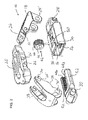
- FIG. 2 is an exploded isometric view of the adjustable implant of FIGS. 1A-1C ;
- FIG. 3 is a partially assembled isometric view of the adjustable implant of FIGS. 1A-1C ;
- FIGS. 4A-4C are side, top and bottom views, respectively, of the adjustable implant of FIGS. 1A-1C ;
- FIG. 4D is a view similar to FIG. 4A showing a variant implementation of a partial gear engagement between two linking segments of the implant;
- FIGS. 5A-5C are cross-sectional views taken along the line A-A in FIG. 4C , the adjustable implant being shown in a collapsed state, a semi-deployed state, and a fully deployed state, respectively;
- FIGS. 6A-6D are side views of the adjustable implant of FIGS. 1A-1C in a collapsed state, two intermediate positions, and a fully deployed state, respectively, illustrating a strain-limiting configuration according to an aspect of the present invention
- FIG. 7A is an isometric view of an alternative implementation of an adjustable implant, constructed and operative according to an embodiment of the present invention, shown in a semi-deployed state;
- FIG. 7B is a center-plane cross-sectional view taken through the adjustable implant of FIG. 7A ;
- FIG. 8 is an exploded isometric view of the adjustable implant of FIG. 7A ;
- FIGS. 9A and 9B are side views of a further implementation of an adjustable implant, constructed and operative according to an embodiment of the present invention, shown in a collapsed state and a deployed state, respectively;
- FIG. 10 is an exploded isometric view of the adjustable implant of FIGS. 9A and 9B ;
- FIGS. 11A and 11B are isometric views of a further variant implementation of an adjustable implant, constructed and operative according to an embodiment of the present invention, shown in a collapsed state and a deployed state.
- the present invention is an adjustable implant.
- FIGS. 1A-8 illustrate a first aspect of the present invention which provides a gear-like mechanical engagement between links of a four-pivot-axis adjustable implant structure to define the adjustment motion.
- FIGS. 1A-6D and 9A-10 illustrate a second aspect of the present invention according to which complementary cooperating surfaces distinct from the articulating joints of an adjustable implant are shaped and positioned such that they provide additional support under conditions of loading of the implant to oppose the resulting strain.
- a third aspect of the present invention exemplified in the various illustrated embodiments relates to a mechanism for adjusting the length of a telescopic body, and hence adjusting the state of the implant.
- the first and second aspects of the invention may equally be implemented in adjustable implants which employ adjustment mechanisms other than the telescopic adjustment of the second aspect of the present invention, and that the telescopic body adjustment mechanism may be used in any or all implants which change their length, without requiring the features of the other aspects of the invention, and in some cases, without the presence of any deflectable linkage of the types to which the other aspects of the invention apply.
- FIGS. 1A-6D illustrate a first embodiment of an adjustable implant, generally designated 10 , illustrative of certain aspects of the present invention.
- Adjustable implant 10 has a telescopic body 12 including a first portion 14 and a second portion 16 .
- First and second portions 14 and 16 are in sliding engagement such that a length of the telescopic body is adjustable from a first length to a second length.
- adjustable implant 10 also has a deflectable linkage including at least two, and in this case three, interconnected segments 18 , 20 and 22 of which segment 18 is a first end segment (or “linking segment”) in articulated connection with first portion 14 and segment 22 is a second end segment (or “linking segment”) in articulated connection with second portion 16 .
- the structure is such that adjustment of a length of the telescopic body causes a corresponding deflection of the deflectable linkage, as best illustrated in FIGS.
- Implant 10 of this example has four distinct pivotal connections each having one or more pivot pin whose central axis defines a distinct pivot axis: a first pivot axis 24 between first end segment 18 and intermediate segment 20 ; a second pivot axis 26 between intermediate segment 20 and second end segment 22 ; a third pivot axis 28 between first end segment 18 and first portion 14 ; and a fourth pivot axis 30 between second end segment 22 and second portion 16 .
- the distance between pivot axes 28 and 30 is adjustable, in this case by telescopic adjustment of telescopic body 12 , so as to adjust the shape of the implant.
- a structure with rigid links interconnected at four pivot axes does not inherently define a unique geometry, and could in principle allow a rocking motion of intermediate segment 20 relative to telescopic body 12 .
- a first aspect of the present invention addresses this issue by reducing the degrees of freedom of the four-pivot-axis so that rotation about two adjacent axes, in this case, axes 24 and 26 occurs in a fixed ratio, most preferably equal and opposite. This results in a stable and well-defined orientation of intermediate segment 20 at every stage of the adjustment process, providing, for example, parallel motion between telescopic body 12 and intermediate segment 20 as illustrated here.
- first linking segment 18 and second linking segment 22 are formed with projecting features configured to provide a partial gear engagement between the segments.
- first linking segment 18 is formed with a gear tooth 32 while second linking segment 22 is formed with projections defining therebetween a complementary tooth trough 34 for receiving gear tooth 32 .
- Tooth 32 and trough 34 are preferably partial profiles of corresponding virtual gear wheels centered at pivot axes 24 and 26 , respectively, and most preferably have standard involute gear geometry, as is well known in the field of gears.
- FIG. 4D shows schematically a variant implementation in which the gear configuration is implemented with a plurality of teeth, specifically, two teeth 32 and one interposed trough 34 as part of segment 18 and two troughs 34 with one interposed tooth 32 as part of segment 22 .
- the inter-axis lengths of linking segment 18 (between axes 24 , 28 ) and linking segment 22 (between axes 26 , 30 ) are equal, and the partial gear engagement employs tooth/trough profiles corresponding to virtual gears of the same sizes/angular pitch.
- the line between axes 24 and 26 corresponding to the orientation of intermediate segment 20 , remains parallel to the length of telescopic body 12 (or a line joining axes 28 and 30 ).
- linking segments of differing inter-axis lengths and/or by employing an asymmetric partial gear engagement other desired geometries of motion can be achieved, such as various combinations of adjustable spacing and angle of inclination.
- the form of the motion is predefined by the structure, and the device is preferably stable against any rocking motion in each position over its range of motion.
- This aspect of the present invention may be implemented in any implant in which the distance between axes 28 and 30 can be adjusted. Examples include any and all cases in which a screw (bolt) is employed to adjust a length of a base/body between axes 28 and 30 , and all forms of telescopic bodies, whether using an internal adjustment mechanism such as that described herein or whether adjusted by an external/removable actuator mechanism. Additionally, this aspect of the present invention may be implemented in cases where a base of the implant is of fixed length, but where an adjustment mechanism displaces one or both of pivot axes 28 and 30 along the base so as to vary a distance between them.
- intermediate segment 20 is formed with a tissue contact surface 21 which, in particularly preferred implementations, extends along more than half a maximum length of the telescopic body.
- This tissue contact surface together with the outward-facing lower surface(s) of telescopic body 12 provide opposing contact surfaces which, on adjustment of the implant, can be used to push apart tissues to achieve a desired extent of separation, distraction or height restoration, all according to the particular application.
- a deflectable linkage such as the three-segment linkage of adjustable implant 10 or a two-segment linkage such as that of adjustable implant 200 described below.
- the motion of the adjustable implants described herein is primarily defined by the geometry of the pivot axes and adjustment of the telescopic body, optionally further defined by a partial gear arrangement according to the first aspect of the present invention described above. However, under conditions of significant applied loading, it may be preferable that part of the load is borne by structures other than the pivot connections.
- first portion 14 of telescopic body 12 and second end segment 22 of the deflectable linkage are formed with complementary cooperating surfaces shaped such that, during adjustment of a length of telescopic body 12 and corresponding deflection of the deflectable linkage, relative motion of first portion 14 and second end segment 22 maintains the cooperating surfaces in strain-limiting proximity.
- Stress-limiting proximity is used herein in the description and claims to refer to two components which are either in contact with each other or which are in proximity with each other to the extent that, when a load is applied to the implant sufficient to elastically deform the implant, the surfaces of the components come into contact within the range of elastic deformation, i.e., before the elastic limit of any of the components is exceeded.
- such contact occurs during the “initial stages” of elastic deformation which, for this purpose, may be defined as the first 50%, more preferably the first 10%, and most preferably the first 5%, of linear strain as a proportion of the maximum strain which would bring the implant to its elastic limit.
- the complementary cooperating surfaces effectively serve as a “stop” to limit or resist elastic deformation of the implant, thereby improving the performance of the implant as a whole under conditions of loading.
- an initial gap between the components in strain-limiting proximity may be chosen to be in excess of 50% of the maximum strain which would bring the implant to its elastic limit. This option may be particularly advantageous where it is desired to provide relatively high flexibility of the implant during routine loading while ensuring that the deformation “bottoms-out” and is stopped before approaching levels which might result in damage.
- this strain-limiting (deformation-limiting) feature is most preferably implemented as illustrated here by providing a small abutment surface or edge 36 at the extremity of first portion 14 and a convexly curved bulge 38 along a lower edge of second end segment 22 .
- the shape of the convexly curved bulge is calculated (or empirically derived) to match the path of relative motion between second end segment 22 and edge 36 as the implant is adjusted through its range of motion, thereby ensuring that the desired proximity is maintained throughout the range.
- FIGS. 6A-6D illustrate a sequence of states spanning the range of adjustment, and illustrate a clearance 40 which is preferably maintained according to certain implementations of the present invention between edge 36 and the adjacent region of bulge 38 .
- This clearance as observed in the unstressed state of the implant is in certain preferred implementations small compared to the dimensions of the implant, typically amounting to no more than 10%, and more preferably 5%, of the overall dimension of the implant in the direction of the spacing, even in the collapsed state.
- This clearance preferably remains substantially constant over the range of adjustment of the implant, for example, most preferably varying by no more than ⁇ 20%.
- Provision of a small clearance in the unloaded state of the implant may be advantageous in that it ensures that the strain-limiting features do not add significant frictional resistance to a process of adjusting the implant shape, at least until a stage of deployment where significant loading is encountered. It may also provide a relatively high-flexibility state, as mentioned above.
- first and second end (linking) segments 18 and 22 are forked elements which extend bilaterally on either side of intermediate segment 20 which is disposed internally to those segments.
- these features may be provided on only one side of the forked second end segment 22 or, more preferably, on both sides thereof, thereby maximizing the structural support provided by these configurations under conditions of loading.
- FIGS. 9A-10 illustrate implementation of these features in the context of an adjustable-angle implant 200 in which a first end segment 218 and a second end segment 222 are interconnected so as to be relatively pivotable about a pivot axis 224 .
- First end segment 218 is preferably formed with a tissue contact surface 219 that extends along a major dimension having a length more than half a maximum length of a telescopic body formed by a first portion 214 and a second portion 216 .
- tissue contact surface 219 extends along a major dimension having a length more than half a maximum length of a telescopic body formed by a first portion 214 and a second portion 216 .
- the result is an implant which has an adjustable angle between tissue contact surface 219 and an outwardly facing tissue contact surface 213 of the telescopic base.
- the preferred implementation of adjustable-angle implant 200 as shown also includes strain-limiting features, structurally and functionally equivalent to those described above, including abutment surface or edge 236 and convexly-curved bulge 238 .
- an adjustable implant illustrated herein also exemplify an adjustment mechanism for adjusting a length of a telescopic body which forms at least part of an implant.
- this aspect of the invention is illustrated herein in the context of an adjustable implant of implant 10 , where a change in length of the telescopic body effects a change to a height of a deflectable linkage.
- this aspect of the present invention may be used to advantage in any implant with telescopic adjustment, even if no such deflectable linkage is present, and may be used to advantage in applications in which an initially minimum-length implant is to be extended once within the body as well as application where an initially maximum-length implant is to be shortened within the body.
- the mechanism may also be useful in application where unidirectional actuation (i.e., just elongation or just shortening) without reversibility is sufficient.
- first and second portions 14 and 16 are here configured for sliding engagement such that a length of the telescopic body along an axis of the telescopic body is adjustable.
- a headless bolt 42 having a threaded outer surface 44 between two end abutment surfaces 46 , is deployed in a region of overlap between the first and second portions.
- First portion 14 is formed with entrapment features configured to abut at least one, and preferably both, end abutment surfaces of bolt 42 so as to prevent displacement of bolt 42 relative to first portion 14 in at least one direction along the axis of the telescopic body.
- Second portion 16 is formed with at least one, and preferably two, elongated threaded surfaces 48 a and 48 b , deployed to engage the threaded outer surface of the bolt.
- Elongated threaded surfaces 48 a and 48 b have a length greater than a length of headless bolt 42 .
- the entrapment features of first portion 14 include the upper and lower edges of a slot 50 into which bolt 42 is inserted during assembly, such that the upper and lower edges of the slot abut end abutment surfaces 46 to prevent axial displacement of the bolt relative to first portion 14 .
- Rotation of bolt in that inserted position engages and draws inwards (or if reversed, forces outwards) elongated threaded surfaces 48 a and 48 b , thereby adjusting a length of telescopic body 12 .
- one of end abutment surfaces 46 is preferably formed with a shaped recess, which may be a shallow recess or a through-bore passing along the length of the bolt, to receive a correspondingly shaped tool tip.
- a “trapped” headless bolt 42 within first portion 14 and relatively long threaded surfaces 48 a , 48 b allows the use of a bolt which in some embodiments is shorter than the range of adjustment of the device. This may provide certain advantages such as leaving a larger area available for openings through the implant, for example, to allow bone ingrowth through the implant.
- the range of adjustment of the telescopic body is typically defined primarily by the length of elongated threaded surfaces 48 a , 48 b , which preferably span the range of adjustment corresponding to a difference between a first length L 1 and a second length L 3 ( FIGS. 5A-5C ) of telescopic body 12 .
- the elongated threaded surfaces are integrated with elongated projections 52 which also define sliding abutment surfaces as part of the sliding engagement with first portion 14 .
- first portion 16 is here formed with two inward-facing walls 54 .
- Outer surfaces of elongated projections 52 are configured to move in sliding engagement with inward-facing walls 54 to define the sliding engagement between first and second portions 14 and 16 , while the inward-facing elongated threaded surfaces 48 a , 48 b engage threaded outer surface 44 of bolt 42 .
- Elongated projections 52 are preferably shaped and sized to span a gap between inward-facing walls 54 and threaded outer surface 44 of boll 42 , such that contact between elongated projections 52 and walls 54 prevents any outward flexing of projections 52 and maintains reliable engagement of elongated threaded surfaces 48 a , 48 b with threaded outer surface 44 of bolt 42 .
- FIGS. 5A-5C The operation of the adjustment mechanism can be best understood from FIGS. 5A-5C .
- bolt 42 is engaged with the extremities of threaded surfaces 48 a (and 48 b ), corresponding to the longest state L 1 of telescopic body 12 which, in this embodiment, is also the lowest height H 1 configuration for insertion into the body.
- a suitable tool (not shown) is then inserted along an access channel from the right side of telescopic body 12 as shown, and is used to turn bolt 42 .
- engagement of bolt 42 with threaded surfaces 48 a (and 48 b ) draws second portion 16 towards first portion 14 , as seen in the successive positions of FIGS. 5B and 5C .
- FIGS. 7A-8 illustrate an alternative implementation of an adjustable implant, generally designated 100 , constructed and operative according to a further embodiment of the present invention.
- Implant 100 is generally analogous to implant 10 described above, and equivalent features are labeled with similar reference numerals incremented by 100.
- first portion 114 includes two elongated projections 156 carrying entrapment features in the form of cut-outs 158 which provide surfaces abutting end abutment surfaces 146 of headless bolt 142 .
- Second portion 116 in this case is formed as a block with inward-facing elongated threaded surfaces 148 that are subdivided by slots 160 which are shaped to receive projection 156 .
- FIGS. 9A-10 these illustrate variable-angle implant 200 which was described above in the context of the strain-limiting features.
- the telescopic adjustment mechanism employed in this example is essentially identical to that of implant 10 described above, with equivalent elements labeled similarly with addition of 200 to the reference numerals.
- FIGS. 11A and 11B illustrate a further embodiment of a variable-angle implant, generally designated 300 .
- implant 300 The structure and function of implant 300 are to a large extent analogous to that of implant 10 described above, and similar elements are designated by similar reference numerals with addition of 300 to the number.
- Implant 300 is a variable-angle implant, functionally analogous to implant 200 , but differs from implant 200 primarily in that the first portion of the telescopic body is here implemented as two rigidly interconnected or integrally formed sections 314 a and 314 b .
- Projection 362 provides an anchor point for a delivery system (not shown) for the implant and is not a pivot.
- the effect of this first portion structure is to position the pivotal connection 328 between first portion 314 b and first end segment 318 in the mid-half (i.e., between 25% and 75%) of the maximum length of the implant, and in certain preferred implementations, at a relatively high position above an initial height of pivotal connection 324 .
- This geometry facilitates a range of angles of tissue contact surface 319 which spans from a “negative angle” as shown in FIG. 11A to a “positive angle” as shown in FIG. 11B .
- the negative angle initial configuration may provide advantages in certain application during insertion of the implant into the body by providing a low profile leading end and a wedge-like overall profile for progressively separating tissues during insertion.
- the exemplary non-limiting adjustment mechanism for the telescopic body is essentially similar to that of implant 10 described above, and will not be described further.
- All of the above exemplary embodiments are suitable for use, as is or with minor modifications that will be self-explanatory to a person of ordinary skill in the art, in a wide range of orthopedic applications, and especially in cases where a distance, spacing and/or angle between two tissue surfaces is to be increased or adjusted.
- One non-limiting field of particular relevance is spinal surgery, including devices for intra-body, inter-body placement within or between adjacent vertebral bodies.
- the devices are typically delivered in a low-profile form while held by an elongated holder (not shown), are inserted to the desired target location, and are then adjusted to provide the desired degree of tissue separation and/or angular correction.
- the devices may be used for any approach direction including, but not limited to, various posterior and lateral approach routes.
- Various bone-ingrowth openings are preferably provided to facilitate fusion and/or osteo-integration.
- tissue contact surfaces do not necessarily, or even typically, have contact surfaces which are parallel per se.
- an upper tissue contact surface 21 of implant 10 as best seen in FIGS. 5A-5C is shown with a preset incline to provide slight lordotic angle restoration in addition to an overall anatomically-rounded shape towards its extremities.
- the tissue contact surfaces are typically modified by various ridges, projection or other features to enhance mechanical anchoring against tissue surfaces, as well as openings as mentioned above.
- the disclosed implants may be formed from any and all materials or combinations of materials known to be suitable for implementation of surgical implants. Examples include, but are not limited to, titanium, surgical stainless steel and polymers such as PEEK.
Landscapes
- Health & Medical Sciences (AREA)
- Biomedical Technology (AREA)
- Engineering & Computer Science (AREA)
- Orthopedic Medicine & Surgery (AREA)
- Neurology (AREA)
- Life Sciences & Earth Sciences (AREA)
- Animal Behavior & Ethology (AREA)
- General Health & Medical Sciences (AREA)
- Heart & Thoracic Surgery (AREA)
- Veterinary Medicine (AREA)
- Public Health (AREA)
- Oral & Maxillofacial Surgery (AREA)
- Cardiology (AREA)
- Transplantation (AREA)
- Vascular Medicine (AREA)
- Surgery (AREA)
- Molecular Biology (AREA)
- Nuclear Medicine, Radiotherapy & Molecular Imaging (AREA)
- Medical Informatics (AREA)
- Prostheses (AREA)
Abstract
Description
Claims (15)
Priority Applications (1)
| Application Number | Priority Date | Filing Date | Title |
|---|---|---|---|
| US15/520,083 US10433972B2 (en) | 2014-10-21 | 2015-10-21 | Adjustable implant |
Applications Claiming Priority (3)
| Application Number | Priority Date | Filing Date | Title |
|---|---|---|---|
| US201462066430P | 2014-10-21 | 2014-10-21 | |
| US15/520,083 US10433972B2 (en) | 2014-10-21 | 2015-10-21 | Adjustable implant |
| PCT/IL2015/051039 WO2016063283A1 (en) | 2014-10-21 | 2015-10-21 | Adjustable implant |
Related Parent Applications (1)
| Application Number | Title | Priority Date | Filing Date |
|---|---|---|---|
| PCT/IL2015/051039 A-371-Of-International WO2016063283A1 (en) | 2014-10-21 | 2015-10-21 | Adjustable implant |
Related Child Applications (1)
| Application Number | Title | Priority Date | Filing Date |
|---|---|---|---|
| US16/592,970 Continuation US11298239B2 (en) | 2014-10-21 | 2019-10-04 | Adjustable implant |
Publications (2)
| Publication Number | Publication Date |
|---|---|
| US20170312090A1 US20170312090A1 (en) | 2017-11-02 |
| US10433972B2 true US10433972B2 (en) | 2019-10-08 |
Family
ID=55760382
Family Applications (3)
| Application Number | Title | Priority Date | Filing Date |
|---|---|---|---|
| US15/520,083 Active US10433972B2 (en) | 2014-10-21 | 2015-10-21 | Adjustable implant |
| US16/592,970 Active 2036-04-27 US11298239B2 (en) | 2014-10-21 | 2019-10-04 | Adjustable implant |
| US17/713,612 Pending US20220226123A1 (en) | 2014-10-21 | 2022-04-05 | Adjustable Implant |
Family Applications After (2)
| Application Number | Title | Priority Date | Filing Date |
|---|---|---|---|
| US16/592,970 Active 2036-04-27 US11298239B2 (en) | 2014-10-21 | 2019-10-04 | Adjustable implant |
| US17/713,612 Pending US20220226123A1 (en) | 2014-10-21 | 2022-04-05 | Adjustable Implant |
Country Status (2)
| Country | Link |
|---|---|
| US (3) | US10433972B2 (en) |
| WO (1) | WO2016063283A1 (en) |
Cited By (1)
| Publication number | Priority date | Publication date | Assignee | Title |
|---|---|---|---|---|
| US11298239B2 (en) | 2014-10-21 | 2022-04-12 | Seaspine, Inc. | Adjustable implant |
Families Citing this family (25)
| Publication number | Priority date | Publication date | Assignee | Title |
|---|---|---|---|---|
| US9039768B2 (en) | 2006-12-22 | 2015-05-26 | Medos International Sarl | Composite vertebral spacers and instrument |
| US20090248092A1 (en) * | 2008-03-26 | 2009-10-01 | Jonathan Bellas | Posterior Intervertebral Disc Inserter and Expansion Techniques |
| US9526620B2 (en) | 2009-03-30 | 2016-12-27 | DePuy Synthes Products, Inc. | Zero profile spinal fusion cage |
| US9393129B2 (en) | 2009-12-10 | 2016-07-19 | DePuy Synthes Products, Inc. | Bellows-like expandable interbody fusion cage |
| US11529241B2 (en) | 2010-09-23 | 2022-12-20 | DePuy Synthes Products, Inc. | Fusion cage with in-line single piece fixation |
| US20120078373A1 (en) | 2010-09-23 | 2012-03-29 | Thomas Gamache | Stand alone intervertebral fusion device |
| US20120078372A1 (en) | 2010-09-23 | 2012-03-29 | Thomas Gamache | Novel implant inserter having a laterally-extending dovetail engagement feature |
| US9271836B2 (en) | 2012-03-06 | 2016-03-01 | DePuy Synthes Products, Inc. | Nubbed plate |
| EP3281609B1 (en) | 2012-05-29 | 2019-02-27 | NLT Spine Ltd. | Expanding implant |
| US10182921B2 (en) | 2012-11-09 | 2019-01-22 | DePuy Synthes Products, Inc. | Interbody device with opening to allow packing graft and other biologics |
| US8663332B1 (en) | 2012-12-13 | 2014-03-04 | Ouroboros Medical, Inc. | Bone graft distribution system |
| US9186259B2 (en) | 2013-09-09 | 2015-11-17 | Ouroboros Medical, Inc. | Expandable trials |
| US9545283B2 (en) * | 2013-12-23 | 2017-01-17 | Jmea Corporation | Devices and methods for preparation of vertebral members |
| US9060876B1 (en) | 2015-01-20 | 2015-06-23 | Ouroboros Medical, Inc. | Stabilized intervertebral scaffolding systems |
| US10500061B2 (en) * | 2015-08-13 | 2019-12-10 | K2M, Inc. | Adjustable spinal implant |
| AU2017203369B2 (en) * | 2016-05-20 | 2022-04-28 | Howmedica Osteonics Corp. | Expandable interbody implant with lordosis correction |
| WO2018015964A1 (en) | 2016-07-21 | 2018-01-25 | Nlt Spine Ltd. | Expandable implant |
| US9883953B1 (en) | 2016-09-21 | 2018-02-06 | Integrity Implants Inc. | Stabilized laterovertically-expanding fusion cage systems with tensioner |
| FR3058044A1 (en) * | 2016-10-27 | 2018-05-04 | Ldr Medical | EXPANDABLE INTERSOMATIC CAGE |
| FR3058043B1 (en) * | 2016-10-27 | 2020-11-13 | Ldr Medical | EXPANDABLE INTERSOMATIC CAGE |
| JP7085554B2 (en) | 2017-01-10 | 2022-06-16 | インテグリティ インプランツ インコーポレイテッド | Deployable intervertebral fusion device |
| US10940016B2 (en) | 2017-07-05 | 2021-03-09 | Medos International Sarl | Expandable intervertebral fusion cage |
| CN111031969A (en) | 2017-07-24 | 2020-04-17 | 整体植入有限公司 | Surgical implant and related methods |
| CN111989056A (en) | 2018-03-01 | 2020-11-24 | 正诚植入公司 | Expandable fusion device with independent expansion system |
| US10722380B1 (en) * | 2019-02-04 | 2020-07-28 | Bret Michael Berry | Laterally expandable spinal implant |
Citations (7)
| Publication number | Priority date | Publication date | Assignee | Title |
|---|---|---|---|---|
| US20040193158A1 (en) * | 2002-06-25 | 2004-09-30 | Roy Lim | Minimally invasive expanding spacer and method |
| US20060241643A1 (en) * | 2002-06-25 | 2006-10-26 | Roy Lim | Minimally invasive expanding spacer and method |
| US20110077738A1 (en) * | 2009-09-28 | 2011-03-31 | Lfc Sp. Z.O.O. | Device for surgical displacement of vertebrae |
| US20130190877A1 (en) * | 2012-01-23 | 2013-07-25 | Mark Patrick Medina | Implant apparatus and method including tee and screw mechanism for spinal fusion |
| US20140012383A1 (en) * | 2011-02-14 | 2014-01-09 | Imds Corporation | Expandable intervertebral implants and instruments |
| US8777993B2 (en) | 2011-07-14 | 2014-07-15 | Nlt Spine Ltd | Laterally deflectable implant |
| US20160100955A1 (en) * | 2014-10-09 | 2016-04-14 | Warsaw Orthopedic, Inc. | Spinal implant system and method |
Family Cites Families (2)
| Publication number | Priority date | Publication date | Assignee | Title |
|---|---|---|---|---|
| JP5458995B2 (en) | 2010-03-18 | 2014-04-02 | 日本電気株式会社 | System structure management apparatus, system structure management method, and program |
| WO2016063283A1 (en) | 2014-10-21 | 2016-04-28 | Nlt Spine Ltd. | Adjustable implant |
-
2015
- 2015-10-21 WO PCT/IL2015/051039 patent/WO2016063283A1/en active Application Filing
- 2015-10-21 US US15/520,083 patent/US10433972B2/en active Active
-
2019
- 2019-10-04 US US16/592,970 patent/US11298239B2/en active Active
-
2022
- 2022-04-05 US US17/713,612 patent/US20220226123A1/en active Pending
Patent Citations (7)
| Publication number | Priority date | Publication date | Assignee | Title |
|---|---|---|---|---|
| US20040193158A1 (en) * | 2002-06-25 | 2004-09-30 | Roy Lim | Minimally invasive expanding spacer and method |
| US20060241643A1 (en) * | 2002-06-25 | 2006-10-26 | Roy Lim | Minimally invasive expanding spacer and method |
| US20110077738A1 (en) * | 2009-09-28 | 2011-03-31 | Lfc Sp. Z.O.O. | Device for surgical displacement of vertebrae |
| US20140012383A1 (en) * | 2011-02-14 | 2014-01-09 | Imds Corporation | Expandable intervertebral implants and instruments |
| US8777993B2 (en) | 2011-07-14 | 2014-07-15 | Nlt Spine Ltd | Laterally deflectable implant |
| US20130190877A1 (en) * | 2012-01-23 | 2013-07-25 | Mark Patrick Medina | Implant apparatus and method including tee and screw mechanism for spinal fusion |
| US20160100955A1 (en) * | 2014-10-09 | 2016-04-14 | Warsaw Orthopedic, Inc. | Spinal implant system and method |
Cited By (1)
| Publication number | Priority date | Publication date | Assignee | Title |
|---|---|---|---|---|
| US11298239B2 (en) | 2014-10-21 | 2022-04-12 | Seaspine, Inc. | Adjustable implant |
Also Published As
| Publication number | Publication date |
|---|---|
| US20200030110A1 (en) | 2020-01-30 |
| WO2016063283A1 (en) | 2016-04-28 |
| US20220226123A1 (en) | 2022-07-21 |
| US11298239B2 (en) | 2022-04-12 |
| US20170312090A1 (en) | 2017-11-02 |
Similar Documents
| Publication | Publication Date | Title |
|---|---|---|
| US11298239B2 (en) | Adjustable implant | |
| US10149770B2 (en) | Orthopedic implant with adjustable angle between tissue contact surfaces | |
| US11925565B2 (en) | Variable lordosis spacer and related methods of use | |
| US11826263B2 (en) | Expandable fusion device and method of installation thereof | |
| US20220354664A1 (en) | Bodiless bone fusion device, apparatus and method | |
| US10779957B2 (en) | Expandable fusion device and method of installation thereof | |
| JP6526031B2 (en) | Variable outpost spacer and related method of use | |
| EP2155117B1 (en) | Adjustable intervertebral implant | |
| JP6479010B2 (en) | Interbody fusion device with self-fixation mechanism | |
| JP6654559B2 (en) | Expandable fixing device and method of installation | |
| EP3169279B1 (en) | Spinal cage | |
| US20170105767A1 (en) | Vertebral facet joint fusion implant and method for fusion | |
| US9414861B2 (en) | Dynamic stabilization device | |
| JP2020011082A (en) | Apparatus for bone stabilization and extension and methods of use | |
| AU2014334526B2 (en) | Retrograded hammertoe compression screw implant and methods of implanting the same | |
| US20130053963A1 (en) | Lumbar fusion device | |
| JP2018502693A (en) | Facet joint implant | |
| US11426289B2 (en) | Pedicle-based intradiscal fixation devices and methods | |
| US20220354662A1 (en) | Pedicle-based intradiscal fixation devices and methods |
Legal Events
| Date | Code | Title | Description |
|---|---|---|---|
| AS | Assignment |
Owner name: NLT SPINE LTD., ISRAEL Free format text: ASSIGNMENT OF ASSIGNORS INTEREST;ASSIGNORS:SHARABANI, NETANEL;LOEBL, ODED;TOUBIA, DIDIER;REEL/FRAME:042094/0393 Effective date: 20170413 |
|
| AS | Assignment |
Owner name: SEASPINE, INC., CALIFORNIA Free format text: ASSIGNMENT OF ASSIGNORS INTEREST;ASSIGNOR:NLT SPINE LTD.;REEL/FRAME:046144/0540 Effective date: 20180508 |
|
| AS | Assignment |
Owner name: WELLS FARGO BANK, NATIONAL ASSOCIATION, CALIFORNIA Free format text: SECURITY INTEREST;ASSIGNORS:SEASPINE HOLDINGS CORPORATION;SEASPINE ORTHOPEDICS CORPORATION;SEASPINE, INC.;AND OTHERS;REEL/FRAME:046523/0946 Effective date: 20151224 |
|
| STPP | Information on status: patent application and granting procedure in general |
Free format text: FINAL REJECTION MAILED |
|
| STPP | Information on status: patent application and granting procedure in general |
Free format text: NOTICE OF ALLOWANCE MAILED -- APPLICATION RECEIVED IN OFFICE OF PUBLICATIONS |
|
| STPP | Information on status: patent application and granting procedure in general |
Free format text: PUBLICATIONS -- ISSUE FEE PAYMENT VERIFIED |
|
| STCF | Information on status: patent grant |
Free format text: PATENTED CASE |
|
| AS | Assignment |
Owner name: WELLS FARGO BANK, NATIONAL ASSOCIATION, AS AGENT, CALIFORNIA Free format text: SECOND AMENDMENT TO PATENT SECURITY AGREEMENT;ASSIGNORS:SEASPINE HOLDINGS CORPORATION;SEASPINE ORTHOPEDICS CORPORATION;SEASPINE, INC.;AND OTHERS;REEL/FRAME:060715/0395 Effective date: 20220715 |
|
| AS | Assignment |
Owner name: 7D SURGICAL USA INC., CALIFORNIA Free format text: RELEASE BY SECURED PARTY;ASSIGNOR:WELLS FARGO BANK, NATIONAL ASSOCIATION;REEL/FRAME:062336/0593 Effective date: 20230105 Owner name: SEASPINE ORTHOPEDICS INTERMEDIATECO, INC., CALIFORNIA Free format text: RELEASE BY SECURED PARTY;ASSIGNOR:WELLS FARGO BANK, NATIONAL ASSOCIATION;REEL/FRAME:062336/0593 Effective date: 20230105 Owner name: THEKEN SPINE, LLC, CALIFORNIA Free format text: RELEASE BY SECURED PARTY;ASSIGNOR:WELLS FARGO BANK, NATIONAL ASSOCIATION;REEL/FRAME:062336/0593 Effective date: 20230105 Owner name: ISOTIS ORTHOBIOLOGICS, INC., CALIFORNIA Free format text: RELEASE BY SECURED PARTY;ASSIGNOR:WELLS FARGO BANK, NATIONAL ASSOCIATION;REEL/FRAME:062336/0593 Effective date: 20230105 Owner name: SEASPINE SALES LLC, CALIFORNIA Free format text: RELEASE BY SECURED PARTY;ASSIGNOR:WELLS FARGO BANK, NATIONAL ASSOCIATION;REEL/FRAME:062336/0593 Effective date: 20230105 Owner name: ISOTIS, INC., CALIFORNIA Free format text: RELEASE BY SECURED PARTY;ASSIGNOR:WELLS FARGO BANK, NATIONAL ASSOCIATION;REEL/FRAME:062336/0593 Effective date: 20230105 Owner name: SEASPINE, INC., CALIFORNIA Free format text: RELEASE BY SECURED PARTY;ASSIGNOR:WELLS FARGO BANK, NATIONAL ASSOCIATION;REEL/FRAME:062336/0593 Effective date: 20230105 Owner name: SEASPINE ORTHOPEDICS CORPORATION, CALIFORNIA Free format text: RELEASE BY SECURED PARTY;ASSIGNOR:WELLS FARGO BANK, NATIONAL ASSOCIATION;REEL/FRAME:062336/0593 Effective date: 20230105 Owner name: SEASPINE HOLDINGS CORPORATION, CALIFORNIA Free format text: RELEASE BY SECURED PARTY;ASSIGNOR:WELLS FARGO BANK, NATIONAL ASSOCIATION;REEL/FRAME:062336/0593 Effective date: 20230105 |
|
| AS | Assignment |
Owner name: JPMORGAN CHASE BANK, N.A., AS ADMINISTRATIVE ASSISTANT, ILLINOIS Free format text: SECURITY INTEREST;ASSIGNORS:SEASPINE ORTHOPEDICS CORPORATION;SEASPINE, INC.;ISOTIS ORTHOBIOLOGICS, INC.;AND OTHERS;REEL/FRAME:062819/0650 Effective date: 20230217 |
|
| FEPP | Fee payment procedure |
Free format text: ENTITY STATUS SET TO UNDISCOUNTED (ORIGINAL EVENT CODE: BIG.); ENTITY STATUS OF PATENT OWNER: LARGE ENTITY |
|
| FEPP | Fee payment procedure |
Free format text: SURCHARGE FOR LATE PAYMENT, LARGE ENTITY (ORIGINAL EVENT CODE: M1554); ENTITY STATUS OF PATENT OWNER: LARGE ENTITY |
|
| MAFP | Maintenance fee payment |
Free format text: PAYMENT OF MAINTENANCE FEE, 4TH YEAR, LARGE ENTITY (ORIGINAL EVENT CODE: M1551); ENTITY STATUS OF PATENT OWNER: LARGE ENTITY Year of fee payment: 4 |
|
| AS | Assignment |
Owner name: BLUE TORCH FINANCE LLC, AS COLLATERAL AGENT, NEW YORK Free format text: SECURITY INTEREST;ASSIGNOR:SEASPINE, INC.;REEL/FRAME:066257/0718 Effective date: 20231106 |