US10419989B2 - Direct link mode for small cells of cellular wireless communication networks - Google Patents
Direct link mode for small cells of cellular wireless communication networks Download PDFInfo
- Publication number
- US10419989B2 US10419989B2 US14/330,504 US201414330504A US10419989B2 US 10419989 B2 US10419989 B2 US 10419989B2 US 201414330504 A US201414330504 A US 201414330504A US 10419989 B2 US10419989 B2 US 10419989B2
- Authority
- US
- United States
- Prior art keywords
- small cell
- user equipment
- direct link
- cell device
- base station
- Prior art date
- Legal status (The legal status is an assumption and is not a legal conclusion. Google has not performed a legal analysis and makes no representation as to the accuracy of the status listed.)
- Active, expires
Links
Images


Classifications
-
- H—ELECTRICITY
- H04—ELECTRIC COMMUNICATION TECHNIQUE
- H04W—WIRELESS COMMUNICATION NETWORKS
- H04W36/00—Hand-off or reselection arrangements
- H04W36/04—Reselecting a cell layer in multi-layered cells
-
- H—ELECTRICITY
- H04—ELECTRIC COMMUNICATION TECHNIQUE
- H04W—WIRELESS COMMUNICATION NETWORKS
- H04W84/00—Network topologies
-
- H—ELECTRICITY
- H04—ELECTRIC COMMUNICATION TECHNIQUE
- H04W—WIRELESS COMMUNICATION NETWORKS
- H04W84/00—Network topologies
- H04W84/02—Hierarchically pre-organised networks, e.g. paging networks, cellular networks, WLAN [Wireless Local Area Network] or WLL [Wireless Local Loop]
- H04W84/04—Large scale networks; Deep hierarchical networks
- H04W84/042—Public Land Mobile systems, e.g. cellular systems
- H04W84/045—Public Land Mobile systems, e.g. cellular systems using private Base Stations, e.g. femto Base Stations, home Node B
Definitions
- This disclosure generally relates to facilitating a small cell device to detect direct link opportunities to establish a direct link mode connection to a user equipment based upon monitoring uplink communications from the user equipment to a macro base station, and cooperating with the macro base station to establish a direct link with the user equipment.
- Advanced cellular communication networks allow for deployment of small cell devices (e.g., microcell device, picocell device, femtocell device) that operate in a similar manner to a macro base station (e.g. high powered cellular base station or tower), but with a small cell coverage area that is less than a macro cell coverage area of the macro base station.
- small cell devices e.g., microcell device, picocell device, femtocell device
- a macro base station e.g. high powered cellular base station or tower
- small cell coverage area that is less than a macro cell coverage area of the macro base station.
- small cell devices 130 A, 130 B, and 130 C having respective small cell coverage areas 135 A, 135 B, and 135 C, are deployed within macro cell coverage area 120 of a macro base station 110 .
- Small cell devices 130 A, 130 B, and 130 C can communicate with user equipment 140 A, 140 B, and 140 C wirelessly.
- Small cell devices 130 A, 130 B, and 130 C can communicate with macro base station 110 wirelessly or through wired connection 150 (e.g. backhaul connection).
- a small cell device can have different, less, or more operation states than a macro base station. Thus, it is possible for a small cell device to attain additional flexibility over a macro base station.
- FIG. 2 is a non-limiting example of operation states of a small cell device (e.g. femto base station).
- small cell device In radiation power on/off state 210 , small cell device can control radio frequency components to turn ON or OFF radiation power on one or more frequencies.
- initialization state 220 such as transitioning from radiation power on/off state 210 , small cell device can determine operational parameters for communication on the cellular communication network, such as in a non-limiting example, frequency subcarriers (e.g. channels) to employ and radiation power level for its radio antennae.
- operational state 230 such as transitioning from initialization state 220 , small cell device can operate in two modes, normal operation mode 240 and low duty mode 250 .
- small cell device In normal operation mode 240 , small cell device operates as a macro base station with a smaller cell coverage area. In low duty mode 250 , small cell device turns off or reduces radiation power of its radio antennae periodically or aperiodically to decrease interference with neighboring small cell devices or macro base stations, where available interval state 260 does not have the radiation power reduced or turned off, and unavailable interval state 270 has the radiation power reduced or turned off. It is to be appreciated that small cell device can transition between states and modes as needed according to any suitable criteria or algorithm.
- interference can be an issue.
- all base stations e.g., macro and small cell
- broadcast system information within a fixed set of frequency subcarriers of a signal (e.g., orthogonal frequency division multiplexing).
- neighboring base stations can cause mutual interference on the set of subcarriers used for broadcasting system information.
- increased usage of limited bandwidth for transmitting control information can create inefficiencies.
- a small cell generally services only a few user equipment, periodically broadcasting control information increases the bandwidth usage overhead per user equipment.
- inefficient usage of sub-frames in the downlink/uplink scheduling can also be an issue.
- the basic unit of downlink/uplink scheduling is per sub-frame. There is an increased possibility that a small cell device serves one or a low number of user equipment, therefore occupying an entire sub-frame in the downlink/uplink scheduling for the one or low number of user equipment.
- a small cell device determines an opportunity to connect with a user equipment using a direct link mode by monitoring uplink radio frames from the user equipment to a macro base station device, and in response to identifying the opportunity to connect with the user equipment using the direct link mode, notifies the macro base station device of the opportunity to connect with the user equipment using the direct link mode, receives direct link information for the user equipment from the macro base station device, and establishes a direct link with the user equipment based on the direct link information.
- a listening component is configured to identify a direct link mode opportunity with a user equipment by monitoring uplink radio frames of a macro base station device
- a direct link mode component is configured to, in response to identification of the direct link mode opportunity with the user equipment, notify the macro base station device of the direct link mode opportunity with the user equipment, receive direct link information for the user equipment from the macro base station device, and establish a direct link with the user equipment.
- FIG. 1 illustrates a diagram of an exemplary non-limiting example cellular communication network in which small cell devices, having respective small cell coverage areas, are deployed within macro cell coverage area of a macro base station.
- FIG. 2 illustrates a block diagram of exemplary non-limiting conventional states of a small cell device (e.g. femto base station).
- a small cell device e.g. femto base station
- FIG. 3 illustrates a block diagram of an exemplary non-limiting system for establishing direct link mode communication between a small cell device and a user equipment, in cooperation with a macro base station in accordance with an implementation of this disclosure.
- FIG. 4 illustrates a diagram of an exemplary non-limiting cellular communication network in which small cell devices, having respective small cell coverage areas, are deployed within macro cell coverage area of a macro base station in accordance with an implementation of this disclosure.
- FIG. 5 illustrates a block diagram of exemplary non-limiting states of a type I small cell device.
- FIG. 6 illustrates a block diagram of exemplary non-limiting states of a type II small cell device.
- FIG. 7 illustrates a block diagram of exemplary non-limiting states of a type III small cell device.
- FIG. 8 illustrates an exemplary non-limiting flow diagram for a small cell device to establish a direct link mode connection between the small cell device and a user equipment in accordance with an implementation of this disclosure.
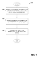
- FIG. 9 illustrates an exemplary non-limiting flow diagram for a macro base station to generate direct link information to establish a direct link mode connection between a small cell device and a user equipment in accordance with an implementation of this disclosure.
- FIG. 10 illustrates an exemplary non-limiting flow diagram for a user equipment to establish a direct link to a small cell device in accordance with an implementation of this disclosure
- FIG. 11 illustrates a block diagram of an exemplary non-limiting networked environment in which various embodiments can be implemented.
- FIG. 12 illustrates a block diagram of an exemplary non-limiting computing system or operating environment in which various embodiments can be implemented.
- a mechanism for a small cell device to monitor uplink communications from one or more user equipment to a macro base station to identify a direct link opportunity to establish a direct link mode connection with a user equipment, and upon identifying the direct link opportunity, cooperating with the macro base station to establish a direct link with the user equipment.
- any suitable communication protocol non-limiting example of which include IEEE 802.11 a ⁇ b ⁇ g ⁇ n ⁇ ac, Global System for Mobile Communications (GSM), Code division multiple access (CDMA), Time division multiple access (TDMA), Bluetooth, Near field communication (NFC), General packet radio service (GPRS), Universal Mobile Telecommunications System (UMTS), Long Term Evolution (LTE), Enhanced Data rates for GSM Evolution (EDGE), Wideband Code Division Multiple Access (W-CDMA), Time Division Synchronous Code Division Multiple Access (TD-SCDMA), Worldwide Interoperability for Microwave Access (WiMAX), Long Term Evolution Advanced (E-UTRA), Evolved High-Speed Packet Access, Universal Mobile Telecommunications System-frequency-division duplexing (UMTS-FDD), Universal Mobile Telecommunications System-time-division duplexing (UMTS-TDD), High Speed Packet Access (HSPA), Evolved High-Speed Packet Access (HSPA+), Enhanced Voice-Data
- GSM Global System for Mobile Communications
- CDMA Code
- FIG. 3 depicts a system 300 for establishing direct link mode communication between a small cell device 310 and user equipment 360 , in cooperation with macro base station 370 .
- System 300 includes small device 310 that includes a listening component 320 that identify a direct link mode opportunity with a user equipment 360 by monitoring uplink radio frames of macro base station 370 .
- Small cell device 310 also includes direct link mode component 330 that cooperates with mode macro base station 370 to employ a direct link mode to establish a direct link with user equipment 360 .
- small cell device 310 includes interface component 340 that interacts with user equipment 360 and macro base station 370 to facilitate exchange of data.
- small cell device 310 includes a data store 350 that can store data generated and received by small cell device 310 , listening component 320 , direct link mode component 330 , and interface component 340 .
- Data store 350 can be stored on any suitable type of storage device, non-limiting examples of which are illustrated with reference to FIGS. 11 and 12 .
- small cell device 310 can concurrently interact with any suitable number of user equipment 360 and macro base stations 370 .
- macro base stations 370 can interact with any suitable number of user equipment 360 and small cell devices 310 concurrently.
- user equipment 360 can interact with any suitable number of macro base stations 370 and small cell devices 310 concurrently.
- Small cell device 310 , user equipment 360 , and macro base station 370 respectively include at least one memory that stores computer executable components and at least one processor that executes the computer executable components stored in the memory, a non-limiting example of which can be found with reference to FIG. 12 .
- Small cell device 310 can communicate via a wireless network with user equipment 360 and via a wired and/or wireless network with macro base station 370 , and user equipment 360 communicate via a wireless network with macro base station 370 .
- User equipment 360 can be any suitable type of device for recording, interacting with, receiving, accessing, or supplying data locally, or remotely over a wireless communication link, non-limiting examples of include a wearable device or a non-wearable device.
- Wearable device can include, for example, heads-up display glasses, a monocle, eyeglasses, contact lens, sunglasses, a headset, a visor, a cap, a helmet, a mask, a headband, clothing, camera, video camera, or any other suitable device capable of recording, interacting with, receiving, accessing, or supplying data that can be worn by a human or non-human user.
- Non-wearable device can include, for example, a mobile device, a mobile phone, a camera, a camcorder, a video camera, personal data assistant, laptop computer, tablet computer, desktop computer, server system, cable set top box, satellite set top box, cable modem, television set, monitor, media extender device, Blu-ray device, DVD (digital versatile disc or digital video disc) device, compact disc device, video game system, portable video game console, audio/video receiver, radio device, portable music player, navigation system, car stereo, motion sensor, infrared sensor, or any other suitable device capable of recording, interacting with, receiving, accessing, or supplying data.
- Small cell device 310 , user equipment 360 , and macro base station 370 can include a user interface (e.g., a web browser or application), that can receive and present displays and data generated locally or remotely.
- a user interface e.g., a web browser or application
- listening component 320 monitoring uplink radio frames of macro base station 370 , such as from a plurality of user equipment 360 to detect a direct link opportunity between the small cell device 310 and a user equipment 360 .
- Listening component 320 can monitor the uplink radio frames on one or more signals, such as in a non-limiting example, an uplink data channel between macro base station 370 and a user equipment 360 , an uplink control channel between macro base station 370 and a user equipment 360 , an uplink reference signal associated with a user equipment 360 .
- listening component 320 can determine that a direct link opportunity exists in the event that a signal strength associated with an uplink radio frame from a user equipment 360 meets a signal strength threshold.
- the signal strength threshold can be pre-defined, set by a system administrator, or dynamically determined.
- Listening component 320 can notify direct link mode component 330 that a determination has been made that a direct link opportunity exists with a user equipment 360 .
- listening component 320 can also determine when an existing direct link opportunity associated with a user equipment 360 no longer exists, such as when a signal strength associated with an uplink radio frame from a user equipment 360 to small cell device 310 or macro base station 370 no longer meets the signal strength threshold.
- small cell devices 310 A, 310 B, and 310 C having respective small cell coverage areas 335 A, 335 B, and 335 C, are deployed within macro cell coverage area 325 of a macro base station 370 .
- Small cell devices 310 A, 310 B, and 310 C can communicate with user equipment 360 A, 360 B, and 360 C wirelessly.
- Small cell devices 310 A, 310 B, and 310 C can communicate with macro base station 370 wirelessly or through wired connection 150 (e.g. backhaul connection).
- Listening component 320 associated with small cell device 310 C can identify that a direct mode link opportunity exists with user equipment 360 C by monitoring uplink radio frames between user equipment 360 C and macro base station 370 .
- direct link mode component 330 notifies macro base station 370 that a direct mode opportunity exists with a user equipment 360 in response to notification from listening component 320 .
- direct link mode component 330 of small cell device 310 C would inform macro base station 370 that a direct link mode opportunity exists with user equipment 360 C.
- macro base station 370 in response to receiving notification of the direct mode opportunity exists with user equipment 360 , can transmit user equipment identification information associated with user equipment 360 to small cell device 310 , and can optionally also transmit small cell device identification information associated with small cell device 310 to user equipment 360 .
- the user equipment identification information allows small cell device 310 to identify user equipment 360 .
- the small cell device identification information allows user equipment 360 to identify small cell device 310 .
- macro base station 370 can transmit user equipment identification information associated with user equipment 360 C to small cell device 310 C, and can optionally also transmit small cell device identification information associated with small cell device 310 C to user equipment 360 C.
- the direct link information e.g. user equipment identification information, and/or small cell device identification information
- Macro base station 370 dynamically assigns one or more radio resources (e.g. frequency subcarriers or channels) to small cell device 310 and user equipment 360 in order for a direct link to be established between small cell device 310 and user equipment 360 .
- radio resources e.g. frequency subcarriers or channels
- macro base station 370 can take into account respective geographic locations of small cell devices 310 in order to reuse radio resources.
- small cell device 310 A can employ radio resource A in a direct link with user equipment 360 A.
- Macro base station 370 can determine that small cell device 310 A is geographically separated from small cell device 310 C by a distance meeting a distance threshold, and can also assign radio resource A to small cell device 310 C and user equipment 360 C to establish a direct link.
- macro base station 370 can determine that small cell device 310 A is not geographically separated from small cell device 310 B by a distance meeting a distance threshold, and assign radio resource B to small cell device 310 B and user equipment 360 B to establish a direct link.
- the distance threshold can be pre-defined, set by a system administrator, or dynamically determined.
- macro base station 370 transmits the assignment of the one or more radio resources to small cell device 310 and user equipment 360 .
- the direct link information can include the assignment of the one or more radio resources.
- Direct mode link component 330 will employ the user equipment identification information and assigned radio resources transmitted from macro base station 370 establish a direct link to user equipment 360 in a direct link mode.
- direct mode link component 330 can send a request to user equipment 360 to form a direct connection (e.g. link) with small cell device 310 .
- User equipment 310 can establish the direct connection with small cell device 310 in response to receiving the request.
- small cell device 310 In direct link mode, small cell device 310 does not broadcast control information, and instead sends control information to user equipment 360 in data packets on the direct link established between small cell device 310 and user equipment 360 .
- this can reduce interference with neighboring small cell devices 310 and macro base station 370 , reduces bandwidth usage for control information on broadcast frequency sub-carriers, and improves overall efficiency of frequency spectrum usage.
- One potential downside with a small cell device 310 not broadcasting control information in direct link mode is that other user equipment 360 that are not in a direct link with small cell device 310 will not be able to discover small cell device 310 . Therefore, three types of small cell devices 310 can be employed, type I, type II, and type III.
- a type I small cell device 310 there is a single mode in operation state of direct link mode.
- FIG. 5 is depicted states of a type I small cell device 310 .
- small cell device can control radio frequency components to turn on or off radiation power on one or more frequencies.
- initialization state 520 such as from transitioning from radiation power on/off state 510 , small cell device can determine operational parameters for communication on the cellular communication network, such as in a non-limiting example, frequency subcarriers to employ and radiation power level for its radio antennae.
- small cell device In operational state 530 , such as from transitioning from initialization state 520 , small cell device can only operate in direct link mode 540 as discussed above with respect to direct link mode.
- a type I small cell device is easy to implement and mitigates interference with neighboring small cell devices 310 and macro base stations 370 in view of no control information being broadcast in direct link mode.
- a type I small cell device 310 can be more appropriate for an area where macro base station has 100% coverage, such as in a non-limiting example, areas geographically close (e.g. within a pre-defined distance) to macro base station 370 .
- a type II small cell device 310 there are modes in operation state of direct link mode, normal operation mode, and low duty mode.
- FIG. 6 is depicted states of a type II small cell device 310 .
- small cell device can control radio frequency components to turn on or off radiation power on one or more frequencies.
- initialization state 620 such as from transitioning from radiation power on/off state 610 , small cell device can determine operational parameters for communication on the cellular communication network, such as in a non-limiting example, frequency subcarriers to employ and radiation power level for its radio antennae.
- small cell device In operational state 630 , such as from transitioning from initialization state 620 , small cell device can operate in three modes, normal operation mode 640 , low duty mode 650 , and direct link mode 680 .
- normal operation mode 640 small cell device operates as a macro base station with a smaller cell coverage area.
- low duty mode 650 small cell device turns off or reduces radiation power of its radio antennae periodically or aperiodically to decrease interference with neighboring small cell devices or macro base stations, where available interval state 660 does not have the radiation power reduced or turned off, and unavailable interval state 670 has the radiation power reduced or turned off.
- Direct link mode 680 is as discussed above with respect to direct link mode.
- small cell device 310 can transition between states and modes as needed according to any suitable switching criteria or algorithm.
- switching criteria for transitioning between direct link mode and normal operation mode or low duty mode can include a number of active user equipment 360 in communication with small cell device 310 meeting a threshold, a number of active user equipment 360 within a geographic area meeting a threshold, number or frequency of communications on a direct link meeting a threshold, a radio link failure report from user equipment 360 in direct link with small cell device 310 , at a predefined or dynamically determined interval. It is to be appreciated that a decision to change mode in an operation state for a small cell device 310 can be made by small cell device 310 or macro base station 370 .
- a type III small cell device 310 there are modes in operation state of direct link mode concurrent with normal operation mode or low duty mode.
- FIG. 7 is depicted states of a type III small cell device 310 .
- small cell device can control radio frequency components to turn on or off radiation power on one or more frequencies.
- initialization state 720 such as from transitioning from radiation power on/off state 710 , small cell device can determine operational parameters for communication on the cellular communication network, such as in a non-limiting example, frequency subcarriers to employ and radiation power level for its radio antennae.
- small cell device can operate in two modes, normal operation mode 740 and low duty mode 750 , while concurrently operating in direct link mode 780 .
- normal operation mode 740 small cell device operates as a macro base station with a smaller cell coverage area, however while concurrently operating in direct link mode 780 .
- low duty mode 650 small cell device turns off or reduces radiation power of its radio antennae periodically or aperiodically to decrease interference with neighboring small cell devices or macro base stations, where available interval state 660 does not have the radiation power reduced or turned off, and unavailable interval state 670 has the radiation power reduced or turned off.
- small cell device In normal operation mode 740 , small cell device, concurrently operates in direct link mode 780 .
- Direct link mode 780 is as discussed above with respect to direct link mode. It is to be appreciated that small cell device 310 can transition between states and modes as needed according to any suitable switching criteria or algorithm.
- FIGS. 8-9 illustrate various methods in accordance with certain disclosed aspects. While, for purposes of simplicity of explanation, the methodologies are shown and described as a series of acts, it is to be understood and appreciated that the disclosed aspects are not limited by the order of acts, as some acts may occur in different orders and/or concurrently with other acts from that shown and described herein. For example, those skilled in the art will understand and appreciate that a methodology can alternatively be represented as a series of interrelated states or events, such as in a state diagram. Moreover, not all illustrated acts may be required to implement a methodology in accordance with certain disclosed aspects. Additionally, it is to be further appreciated that the methodologies disclosed hereinafter and throughout this disclosure are capable of being stored on an article of manufacture to facilitate transporting and transferring such methodologies to computers.
- a direct link opportunity between the small cell device and the user equipment is identified by monitoring uplink radio frames from one or more user equipment to a macro base station (e.g., by a listening component 320 or small cell device 310 ).
- the macro base station is notified of the direct link opportunity between the small cell device and the user equipment (e.g., by a direct link mode component 330 , interface component 340 , or small cell device 310 ).
- direct link information for establishing a direct link between the small cell device and the user equipment is received from the macro base station (e.g., by a direct link mode component 330 , interface component 340 , or small cell device 310 ).
- a direct link between the small cell device and the user equipment is established using the direct link information (e.g., by a direct link mode component 330 , interface component 340 , or small cell device 310 ).
- a method 900 for a macro base station to generate direct link information to establish a direct link mode connection between a small cell device and a user equipment is depicted.
- a direct link opportunity between the small cell device and the user equipment is received from the small cell device (e.g., by a macro base station 370 ).
- the direct link information for establishing the direct link between the small cell device and the user equipment is determined (e.g., by macro base station 370 ).
- the direct link information is transmitted to the small cell device, and optionally to the user equipment (e.g., by macro base station 370 ).
- a request to establish a direct link is received from the small cell device (e.g., by a user equipment 360 ).
- a direct link is established with the small cell device (e.g., by user equipment 360 ).
- the various embodiments described herein can be implemented in connection with any computer or other client or server device, which can be deployed as part of a computer network or in a distributed computing environment, and can be connected to any kind of data store where media may be found.
- the various embodiments described herein can be implemented in any computer system or environment having any number of memory or storage units, and any number of applications and processes occurring across any number of storage units. This includes, but is not limited to, an environment with server computers and client computers deployed in a network environment or a distributed computing environment, having remote or local storage.
- Distributed computing provides sharing of computer resources and services by communicative exchange among computing devices and systems. These resources and services include the exchange of information, cache storage and disk storage for objects, such as files. These resources and services can also include the sharing of processing power across multiple processing units for load balancing, expansion of resources, specialization of processing, and the like. Distributed computing takes advantage of network connectivity, allowing clients to leverage their collective power to benefit the entire enterprise. In this regard, a variety of devices may have applications, objects or resources that may participate in the various embodiments of this disclosure.
- FIG. 11 provides a schematic diagram of an exemplary networked or distributed computing environment.
- the distributed computing environment comprises computing objects 1110 , 1114 , etc. and computing objects or devices 1118 , 1120 , 1122 , 1124 , 1126 , 1128 , etc., which may include programs, methods, data stores, programmable logic, etc., as represented by applications 1130 , 1132 , 1134 , 1136 , 1138 .
- computing objects 1110 , 1114 , etc. and computing objects or devices 1118 , 1120 , 1122 , 1124 , 1126 , 1128 , etc. may comprise different devices, such as personal digital assistants (PDAs), audio/video devices, mobile phones, MP3 players, personal computers, laptops, tablets, etc.
- PDAs personal digital assistants
- Each computing object 1110 , 1114 , etc. and computing objects or devices 1118 , 1120 , 1122 , 1124 , 1126 , 1128 , etc. can communicate with one or more other computing objects 1110 , 1114 , etc. and computing objects or devices 1118 , 1120 , 1122 , 1124 , 1126 , 1128 , etc. by way of the communications network 1140 , either directly or indirectly.
- network 1140 may comprise other computing objects and computing devices that provide services to the system of FIG. 11 , and/or may represent multiple interconnected networks, which are not shown.
- computing objects or devices 1118 , 1120 , 1122 , 1124 , 1126 , 1128 , etc. can also contain an application, such as applications 1130 , 1132 , 1134 , 1136 , 1138 , that might make use of an API, or other object, software, firmware and/or hardware, suitable for communication with or implementation of various embodiments of this disclosure.
- computing systems can be connected together by wired or wireless systems, by local networks or widely distributed networks.
- networks are coupled to the Internet, which provides an infrastructure for widely distributed computing and encompasses many different networks, though any suitable network infrastructure can be used for exemplary communications made incident to the systems as described in various embodiments herein.
- client is a member of a class or group that uses the services of another class or group.
- a client can be a computer process, e.g., roughly a set of instructions or tasks, that requests a service provided by another program or process.
- a client process may utilize the requested service without having to “know” all working details about the other program or the service itself.
- a client can be a computer that accesses shared network resources provided by another computer, e.g., a server.
- a server e.g., a server
- computing objects or devices 1118 , 1120 , 1122 , 1124 , 1126 , 1128 , etc. can be thought of as clients and computing objects 1110 , 1114 , etc. can be thought of as servers where computing objects 1110 , 1114 , etc.
- any computer can be considered a client, a server, or both, depending on the circumstances. Any of these computing devices may be processing data, or requesting transaction services or tasks that may implicate the techniques for systems as described herein for one or more embodiments.
- a server is typically a remote computer system accessible over a remote or local network, such as the Internet or wireless network infrastructures.
- the client process may be active in a first computer system, and the server process may be active in a second computer system, communicating with one another over a communications medium, thus providing distributed functionality and allowing multiple clients to take advantage of the information-gathering capabilities of the server.
- Any software objects utilized pursuant to the techniques described herein can be provided standalone, or distributed across multiple computing devices or objects.
- the computing objects 1110 , 1112 , etc. can be Web servers, file servers, media servers, etc. with which the client computing objects or devices 1118 , 1120 , 1122 , 1124 , 1126 , 1128 , etc. communicate via any of a number of known protocols, such as the hypertext transfer protocol (HTTP).
- HTTP hypertext transfer protocol
- Objects 1110 , 1112 , etc. may also serve as client computing objects or devices 1118 , 1120 , 1122 , 1124 , 1126 , 1128 , etc., as may be characteristic of a distributed computing environment.
- the techniques described herein can be applied to any suitable device. It is to be understood, therefore, that handheld, portable and other computing devices and computing objects of all kinds are contemplated for use in connection with the various embodiments. Accordingly, the computer described below in FIG. 12 is but one example of a computing device that can be employed with implementing one or more of the systems or methods shown and described in connection with FIGS. 1-10 . Additionally, a suitable server can include one or more aspects of the below computer, such as a media server or other media management server components.
- embodiments can partly be implemented via an operating system, for use by a developer of services for a device or object, and/or included within application software that operates to perform one or more functional aspects of the various embodiments described herein.
- Software may be described in the general context of computer executable instructions, such as program modules, being executed by one or more computers, such as client workstations, servers or other devices.
- computers such as client workstations, servers or other devices.
- client workstations such as client workstations, servers or other devices.
- FIG. 12 thus illustrates an example of a suitable computing system environment 1200 in which one or aspects of the embodiments described herein can be implemented, although as made clear above, the computing system environment 1200 is only one example of a suitable computing environment and is not intended to suggest any limitation as to scope of use or functionality. Neither is the computing environment 1200 be interpreted as having any dependency or requirement relating to any one or combination of components illustrated in the exemplary operating environment 1200 .
- FIG. 12 an exemplary computing device for implementing one or more embodiments in the form of a computer 1210 is depicted.
- Components of computer 1210 may include, but are not limited to, a processing unit 1220 , a system memory 1230 , and a system bus 1222 that couples various system components including the system memory to the processing unit 1220 .
- Computer 1210 typically includes a variety of computer readable media and can be any available media that can be accessed by computer 1210 .
- the system memory 1230 may include computer storage media in the form of volatile and/or nonvolatile memory such as read only memory (ROM) and/or random access memory (RAM).
- system memory 1230 may also include an operating system, application programs, other program modules, and program data.
- a user can enter commands and information into the computer 1210 through input devices 1240 , non-limiting examples of which can include a keyboard, keypad, a pointing device, a mouse, stylus, touchpad, touchscreen, trackball, motion detector, camera, microphone, joystick, game pad, scanner, or any other device that allows the user to interact with computer 1210 .
- input devices 1240 non-limiting examples of which can include a keyboard, keypad, a pointing device, a mouse, stylus, touchpad, touchscreen, trackball, motion detector, camera, microphone, joystick, game pad, scanner, or any other device that allows the user to interact with computer 1210 .
- a monitor or other type of display device is also connected to the system bus 1222 via an interface, such as output interface 1250 .
- computers can also include other peripheral output devices such as speakers and a printer, which may be connected through output interface 1250 .
- the computer 1210 may operate in a networked or distributed environment using logical connections to one or more other remote computers, such as remote computer 1270 via network interface 1260 .
- the remote computer 1270 may be a personal computer, a server, a router, a network PC, a peer device or other common network node, or any other remote media consumption or transmission device, and may include any or all of the elements described above relative to the computer 1210 .
- the logical connections depicted in FIG. 12 include a network 1272 , such local area network (LAN) or a wide area network (WAN), but may also include other networks/buses e.g., cellular networks.
- LAN local area network
- WAN wide area network
- an appropriate API e.g., an appropriate API, tool kit, driver code, operating system, control, standalone or downloadable software object, etc. which enables applications and services to take advantage of the techniques described herein.
- embodiments herein are contemplated from the standpoint of an API (or other software object), as well as from a software or hardware object that implements one or more aspects described herein.
- various embodiments described herein can have aspects that are wholly in hardware, partly in hardware and partly in software, as well as in software.
- exemplary is used herein to mean serving as an example, instance, or illustration.
- aspects disclosed herein are not limited by such examples.
- any aspect or design described herein as “exemplary” is not necessarily to be construed as preferred or advantageous over other aspects or designs, nor is it meant to preclude equivalent exemplary structures and techniques known to those of ordinary skill in the art.
- the terms “includes,” “has,” “contains,” and other similar words are used in either the detailed description or the claims, for the avoidance of doubt, such terms are intended to be inclusive in a manner similar to the term “comprising” as an open transition word without precluding any additional or other elements.
- Computer-readable storage media can be any available storage media that can be accessed by the computer, is typically of a non-transitory nature, and can include both volatile and nonvolatile media, removable and non-removable media.
- Computer-readable storage media can be implemented in connection with any method or technology for storage of information such as computer-readable instructions, program modules, structured data, or unstructured data.
- Computer-readable storage media can include, but are not limited to, RAM, ROM, EEPROM, flash memory or other memory technology, CD-ROM, digital versatile disk (DVD) or other optical disk storage, magnetic cassettes, magnetic tape, magnetic disk storage or other magnetic storage devices, or other tangible and/or non-transitory media which can be used to store desired information.
- Computer-readable storage media can be accessed by one or more local or remote computing devices, e.g., via access requests, queries or other data retrieval protocols, for a variety of operations with respect to the information stored by the medium.
- communications media typically embody computer-readable instructions, data structures, program modules or other structured or unstructured data in a data signal such as a modulated data signal, e.g., a carrier wave or other transport mechanism, and includes any information delivery or transport media.
- modulated data signal or signals refers to a signal that has one or more of its characteristics set or changed in such a manner as to encode information in one or more signals.
- communication media include wired media, such as a wired network or direct-wired connection, and wireless media such as acoustic, RF, infrared and other wireless media.
- a component may be, but is not limited to being, a process running on a processor, a processor, an object, an executable, a thread of execution, a program, and/or a computer.
- a component may be, but is not limited to being, a process running on a processor, a processor, an object, an executable, a thread of execution, a program, and/or a computer.
- an application running on computer and the computer can be a component.
- One or more components may reside within a process and/or thread of execution and a component may be localized on one computer and/or distributed between two or more computers.
- a “device” can come in the form of specially designed hardware; generalized hardware made specialized by the execution of software thereon that enables the hardware to perform specific function (e.g., coding and/or decoding); software stored on a computer readable medium; or a combination thereof.
- components described herein can examine the entirety or a subset of the data to which it is granted access and can provide for reasoning about or infer states of the system, environment, etc. from a set of observations as captured via events and/or data.
- Inference can be employed to identify a specific context or action, or can generate a probability distribution over states, for example.
- the inference can be probabilistic—that is, the computation of a probability distribution over states of interest based on a consideration of data and events.
- Inference can also refer to techniques employed for composing higher-level events from a set of events and/or data.
- Such inference can result in the construction of new events or actions from a set of observed events and/or stored event data, whether or not the events are correlated in close temporal proximity, and whether the events and data come from one or several event and data sources.
- Various classification (explicitly and/or implicitly trained) schemes and/or systems e.g., support vector machines, neural networks, expert systems, Bayesian belief networks, fuzzy logic, data fusion engines, etc. can be employed in connection with performing automatic and/or inferred action in connection with the claimed subject matter.
- Such classification can employ a probabilistic and/or statistical-based analysis (e.g., factoring into the analysis utilities and costs) to prognose or infer an action that a user desires to be automatically performed.
- a support vector machine (SVM) is an example of a classifier that can be employed. The SVM operates by finding a hyper-surface in the space of possible inputs, where the hyper-surface attempts to split the triggering criteria from the non-triggering events. Intuitively, this makes the classification correct for testing data that is near, but not identical to training data.
- directed and undirected model classification approaches include, e.g., na ⁇ ve Bayes, Bayesian networks, decision trees, neural networks, fuzzy logic models, and probabilistic classification models providing different patterns of independence can be employed. Classification as used herein also is inclusive of statistical regression that is utilized to develop models of priority.
Landscapes
- Engineering & Computer Science (AREA)
- Computer Networks & Wireless Communication (AREA)
- Signal Processing (AREA)
- Mobile Radio Communication Systems (AREA)
Abstract
Description
Claims (25)
Priority Applications (1)
| Application Number | Priority Date | Filing Date | Title |
|---|---|---|---|
| US14/330,504 US10419989B2 (en) | 2013-10-16 | 2014-07-14 | Direct link mode for small cells of cellular wireless communication networks |
Applications Claiming Priority (2)
| Application Number | Priority Date | Filing Date | Title |
|---|---|---|---|
| US201361891860P | 2013-10-16 | 2013-10-16 | |
| US14/330,504 US10419989B2 (en) | 2013-10-16 | 2014-07-14 | Direct link mode for small cells of cellular wireless communication networks |
Publications (2)
| Publication Number | Publication Date |
|---|---|
| US20150105085A1 US20150105085A1 (en) | 2015-04-16 |
| US10419989B2 true US10419989B2 (en) | 2019-09-17 |
Family
ID=52810087
Family Applications (1)
| Application Number | Title | Priority Date | Filing Date |
|---|---|---|---|
| US14/330,504 Active 2034-11-26 US10419989B2 (en) | 2013-10-16 | 2014-07-14 | Direct link mode for small cells of cellular wireless communication networks |
Country Status (1)
| Country | Link |
|---|---|
| US (1) | US10419989B2 (en) |
Families Citing this family (3)
| Publication number | Priority date | Publication date | Assignee | Title |
|---|---|---|---|---|
| EP2957116B1 (en) * | 2013-02-12 | 2017-01-25 | Nokia Solutions and Networks Oy | System and method for managing user equipment movement driven cell system load balancing |
| EP3354069B1 (en) * | 2015-09-24 | 2020-12-02 | Sony Corporation | Telecommunications apparatus and methods for routing of d2d traffic |
| CN111526543A (en) * | 2019-02-02 | 2020-08-11 | 索尼公司 | Electronic device, communication method, and storage medium |
Citations (11)
| Publication number | Priority date | Publication date | Assignee | Title |
|---|---|---|---|---|
| US20090163216A1 (en) * | 2007-12-19 | 2009-06-25 | Minh Hoang | Proximity detection in a network |
| US20100054145A1 (en) * | 2006-11-17 | 2010-03-04 | Pal Frenger | Mobile Station Communicating with a Base Station via a Separate Uplink when the Parameters of Channel Quality Fall Below the Predefined Thresholds |
| US20100329206A1 (en) * | 2009-06-30 | 2010-12-30 | Thome Timothy A | Dual idle-traffic state of wireless communication device |
| US20110051640A1 (en) * | 2009-08-26 | 2011-03-03 | Rajaram Ramesh | System and methods for reducing power consumed by a base station |
| US20110053604A1 (en) * | 2009-04-16 | 2011-03-03 | Byoung Hoon Kim | Scheduling method based on hierarchical cell structure and femto base station for the same |
| US20110086636A1 (en) * | 2009-10-09 | 2011-04-14 | Industrial Technology Research Institute | System and method for home cellular networks |
| US20110275361A1 (en) * | 2009-11-06 | 2011-11-10 | Qualcomm Incorporated | Restricting access point transmissions |
| US20110294508A1 (en) * | 2010-05-28 | 2011-12-01 | Samsung Electronics Co., Ltd. | Apparatus and method for supporting mobility in a heterogeneous wireless communication system |
| US20130003680A1 (en) * | 2010-03-23 | 2013-01-03 | Sumitomo Electric Industries, Ltd. | Base station device and terminal device |
| US20140128078A1 (en) * | 2012-11-02 | 2014-05-08 | Research In Motion Limited | Wireless communication in heterogeneous networks |
| US20150271743A1 (en) * | 2012-10-08 | 2015-09-24 | Nokia Solutions And Networks Oy | Small Cell Discovery |
Family Cites Families (4)
| Publication number | Priority date | Publication date | Assignee | Title |
|---|---|---|---|---|
| US7814714B2 (en) * | 2008-01-30 | 2010-10-19 | Cornbelt Fabric Structures, Llc | Apparatus and system to increase capacity of granular material storage structures |
| CN101944577B (en) * | 2009-07-07 | 2013-10-09 | 鸿富锦精密工业(深圳)有限公司 | Fixing structure |
| DE102010001790A1 (en) * | 2010-02-10 | 2011-08-11 | Huf Hülsbeck & Fürst GmbH & Co. KG, 42551 | closing device |
| US9382722B2 (en) * | 2013-07-25 | 2016-07-05 | Valmont West Coast Engineering Ltd. | Anti-theft assembly for inhibiting theft of cable from light poles |
-
2014
- 2014-07-14 US US14/330,504 patent/US10419989B2/en active Active
Patent Citations (11)
| Publication number | Priority date | Publication date | Assignee | Title |
|---|---|---|---|---|
| US20100054145A1 (en) * | 2006-11-17 | 2010-03-04 | Pal Frenger | Mobile Station Communicating with a Base Station via a Separate Uplink when the Parameters of Channel Quality Fall Below the Predefined Thresholds |
| US20090163216A1 (en) * | 2007-12-19 | 2009-06-25 | Minh Hoang | Proximity detection in a network |
| US20110053604A1 (en) * | 2009-04-16 | 2011-03-03 | Byoung Hoon Kim | Scheduling method based on hierarchical cell structure and femto base station for the same |
| US20100329206A1 (en) * | 2009-06-30 | 2010-12-30 | Thome Timothy A | Dual idle-traffic state of wireless communication device |
| US20110051640A1 (en) * | 2009-08-26 | 2011-03-03 | Rajaram Ramesh | System and methods for reducing power consumed by a base station |
| US20110086636A1 (en) * | 2009-10-09 | 2011-04-14 | Industrial Technology Research Institute | System and method for home cellular networks |
| US20110275361A1 (en) * | 2009-11-06 | 2011-11-10 | Qualcomm Incorporated | Restricting access point transmissions |
| US20130003680A1 (en) * | 2010-03-23 | 2013-01-03 | Sumitomo Electric Industries, Ltd. | Base station device and terminal device |
| US20110294508A1 (en) * | 2010-05-28 | 2011-12-01 | Samsung Electronics Co., Ltd. | Apparatus and method for supporting mobility in a heterogeneous wireless communication system |
| US20150271743A1 (en) * | 2012-10-08 | 2015-09-24 | Nokia Solutions And Networks Oy | Small Cell Discovery |
| US20140128078A1 (en) * | 2012-11-02 | 2014-05-08 | Research In Motion Limited | Wireless communication in heterogeneous networks |
Also Published As
| Publication number | Publication date |
|---|---|
| US20150105085A1 (en) | 2015-04-16 |
Similar Documents
| Publication | Publication Date | Title |
|---|---|---|
| Tran et al. | Joint task offloading and resource allocation for multi-server mobile-edge computing networks | |
| US20220124543A1 (en) | Graph neural network and reinforcement learning techniques for connection management | |
| EP3563595B1 (en) | Methods and devices for radio communications | |
| JP6888082B2 (en) | Facilitating uplink communication waveform selection | |
| US11388644B2 (en) | Apparatus and method for load balancing in wireless communication system | |
| US9955290B2 (en) | Opportunistic offloading of tasks between nearby computing devices | |
| US11800367B2 (en) | Managing resources in CBRS networks | |
| US9503934B2 (en) | System and method for radio access virtualization | |
| DE102022200847A1 (en) | REINFORCING LEARNING FOR MULTIPLE ACCESS TRAFFIC MANAGEMENT | |
| US8892150B2 (en) | Communication method of neighboring terminal and target terminal | |
| US8909157B2 (en) | Optimizing cell traffic load and interference through high interference indicators | |
| Ahmed et al. | Backscatter sensors communication for 6G low-powered NOMA-enabled IoT networks under imperfect SIC | |
| Mukherjee et al. | C2OF2N: a low power cooperative code offloading method for femtolet-based fog network | |
| CN113491094A (en) | Service delivery with federated network and cloud resource management | |
| US20230171639A1 (en) | Communication related to congestion control | |
| US20190045005A1 (en) | Method for replicating data in a network and a network component | |
| Yuvaraj et al. | Binary flower pollination (BFP) approach to handle the dynamic networking conditions to deliver uninterrupted connectivity | |
| US10419989B2 (en) | Direct link mode for small cells of cellular wireless communication networks | |
| EP3011778A1 (en) | Radio channel communication | |
| Sarkar et al. | MAAS: A mobile cloud assisted architecture for handling emergency situations | |
| Ramasamy et al. | EMC2: an emergency management system using mobile cloud computing | |
| EP4250664A1 (en) | Communication related to federated learning | |
| US20200008077A1 (en) | Apparatus for frequency band allocation | |
| JP2020088980A (en) | Control device | |
| CN106465228B (en) | Cell outage compensation method and device |
Legal Events
| Date | Code | Title | Description |
|---|---|---|---|
| AS | Assignment |
Owner name: TRANSPACIFIC IP MANAGEMENT GROUP LTD., CHINA Free format text: ASSIGNMENT OF ASSIGNORS INTEREST;ASSIGNORS:TSENG, YUNG-LAN;HUANG, CHING-YAO;SIGNING DATES FROM 20140903 TO 20140929;REEL/FRAME:034830/0113 |
|
| AS | Assignment |
Owner name: TRANSPACIFIC IP MANAGEMENT GROUP LTD., TAIWAN Free format text: CORRECTON ASSIGNMENT TO CORRECT THE THE FIRST INVENTORS EXECUTION DATE PREVIOUSLY RECORDED AT REEL: 034830 FRAME: 0113. ASSIGNOR(S) HEREBY CONFIRMS THE ASSIGNMENT;ASSIGNORS:TSENG, YUNG-LAN;HUANG, CHING-YAO;SIGNING DATES FROM 20140903 TO 20140927;REEL/FRAME:035927/0677 |
|
| AS | Assignment |
Owner name: DYNAMIC INVENTION LLC, SEYCHELLES Free format text: ASSIGNMENT OF ASSIGNORS INTEREST;ASSIGNOR:TRANSPACIFIC IP MANAGEMENT GROUP LTD.;REEL/FRAME:040205/0789 Effective date: 20161029 |
|
| AS | Assignment |
Owner name: TAIWAN SEMICONDUCTOR MANUFACTURING COMPANY, LTD., Free format text: ASSIGNMENT OF ASSIGNORS INTEREST;ASSIGNOR:DYNAMIC INVENTION LLC;REEL/FRAME:040832/0652 Effective date: 20161115 |
|
| STPP | Information on status: patent application and granting procedure in general |
Free format text: NOTICE OF ALLOWANCE MAILED -- APPLICATION RECEIVED IN OFFICE OF PUBLICATIONS |
|
| STPP | Information on status: patent application and granting procedure in general |
Free format text: PUBLICATIONS -- ISSUE FEE PAYMENT RECEIVED |
|
| STPP | Information on status: patent application and granting procedure in general |
Free format text: PUBLICATIONS -- ISSUE FEE PAYMENT VERIFIED |
|
| STCF | Information on status: patent grant |
Free format text: PATENTED CASE |
|
| MAFP | Maintenance fee payment |
Free format text: PAYMENT OF MAINTENANCE FEE, 4TH YEAR, LARGE ENTITY (ORIGINAL EVENT CODE: M1551); ENTITY STATUS OF PATENT OWNER: LARGE ENTITY Year of fee payment: 4 |