US10401423B2 - Thermal control using phase-change material - Google Patents
Thermal control using phase-change material Download PDFInfo
- Publication number
- US10401423B2 US10401423B2 US15/145,136 US201615145136A US10401423B2 US 10401423 B2 US10401423 B2 US 10401423B2 US 201615145136 A US201615145136 A US 201615145136A US 10401423 B2 US10401423 B2 US 10401423B2
- Authority
- US
- United States
- Prior art keywords
- phase
- change material
- temperature
- liquid
- test
- Prior art date
- Legal status (The legal status is an assumption and is not a legal conclusion. Google has not performed a legal analysis and makes no representation as to the accuracy of the status listed.)
- Active, expires
Links
Images


Classifications
-
- G—PHYSICS
- G01—MEASURING; TESTING
- G01R—MEASURING ELECTRIC VARIABLES; MEASURING MAGNETIC VARIABLES
- G01R31/00—Arrangements for testing electric properties; Arrangements for locating electric faults; Arrangements for electrical testing characterised by what is being tested not provided for elsewhere
- G01R31/28—Testing of electronic circuits, e.g. by signal tracer
- G01R31/2851—Testing of integrated circuits [IC]
- G01R31/2855—Environmental, reliability or burn-in testing
- G01R31/2872—Environmental, reliability or burn-in testing related to electrical or environmental aspects, e.g. temperature, humidity, vibration, nuclear radiation
- G01R31/2874—Environmental, reliability or burn-in testing related to electrical or environmental aspects, e.g. temperature, humidity, vibration, nuclear radiation related to temperature
Definitions
- This specification relates generally to a test system that implements thermal control using phase-change material.
- a phase-change material includes a material that melts or solidifies at certain temperatures.
- heat is absorbed by a PCM when the PCM changes from solid to liquid.
- the heat melts the PCM, turning it into a liquid.
- heat is released by a PCM when the PCM changes from liquid to solid. The heat leaves the PCM, allowing the PCM to cool and to solidify.
- An example test system comprises a test slot to hold a device under test (DUT); a temperature control system comprising a phase-change material, with the temperature control system for maintaining a temperature of the phase-change material in a steady-state condition, with the phase-change material changing phase during a transient condition to affect a temperature of a thermally-conductive structure, and with the steady-state condition being longer in duration than the transient condition; and an air mover to direct air over the thermally-conductive structure and towards the DUT in the test slot in order to affect a temperature of the DUT.
- the example test system may include one or more of the following features, either alone or in combination.
- the temperature control system may comprise a cooling loop to reduce the temperature of the DUT, with the cooling loop comprising: tubing to transport liquid to and from the test slot, with the tubing containing the liquid passing proximate to the phase-change material to allow the phase-change material to cool the liquid, and with the phase change material melting to cool the liquid during the transient condition; and a cooling system to cool the liquid.
- the tubing containing the liquid may pass through or around the phase-change material.
- the temperature control system may be configured to actively control a temperature of a liquid passing in proximity to the phase-change material to enable the thermally-conductive structure to reach a minimum temperature during the transient condition; and the cooling system may be configured to cool the phase-change material during the steady-state condition.
- the cooling system may have a capacity that is less than would be required to enable the thermally-conductive structure to reach the minimum temperature during the transient condition absent the phase-change material.
- the liquid may comprise a heat transfer fluid.
- the temperature control system may comprise a heating loop to increase the temperature of the DUT, with the heating loop comprising: tubing to transport liquid to and from the test slot, with the tubing containing the liquid passing proximate to the phase-change material to allow the phase-change material to add heat to the liquid, and with the phase change material solidifying to add the heat to the liquid during the transient condition; and a heating system to heat the liquid.
- the tubing containing the liquid may pass through or around to the phase-change material.
- the temperature control system may be configured to actively control a temperature of a liquid in proximity to the phase-change material to enable the thermally-conductive structure to reach a maximum temperature during the transient condition; and the heating system is configured to add the heat to the phase-change material during the steady-state condition.
- the heating system may have a capacity that is less than would be required to enable the thermally-conductive structure to reach the maximum temperature during the transient condition absent the phase-change material.
- the liquid may comprise a heat transfer fluid.
- the thermally-conductive structure may comprise one or more metal plates; and the test slot may comprise a shroud to direct air from the air mover over the DUT.
- the phase-change material may comprise a hydrated salt or an organic compound.
- the test system may also comprise a group of test slots, which includes the test slot holding the DUT.
- Each test slot in the group of test slots may comprise a thermally-conductive structure having a temperature that is affected by a temperature of the phase change material.
- Each test slot in the group of test slots may comprise an air mover to direct air over a corresponding thermally-conductive structure and towards a DUT in order to affect a temperature of the DUT.
- the test system of may comprise a temperature sensor to detect a temperature of the DUT; and a control loop to control operation of the air mover based on the temperature detected.
- the temperature control system comprising the phase-change material may enable the thermally-conductive structure to reach a target temperature at a quicker rate during the transient condition than would be reached by the temperature control system absent the phase-change material.
- the temperature control system comprising the phase-change material may reduce peak power demand during the transient condition relative to a peak power demand of the temperature control system absent the phase-change material.
- An example temperature control system for one or more test slots comprises a cooling loop for one or more test slots, with the cooling loop comprising a first liquid and a first phase-change material, with the first phase-change material to remove heat from the first liquid during a first transient condition, with the cooling loop comprising a cooling system to cool the first liquid during a first steady-state condition, and with the first steady state condition being longer in duration than the first transient condition.
- the example temperature control system also comprises a heating loop for one or more test slots, with the heating loop comprising a second liquid and a second phase-change material, with the second phase-change material to add heat to the second liquid during a second transient condition, with the heating loop comprising a heating system to add heat to the second liquid during a second steady-state condition, and with the second steady state condition being longer in duration than the second transient condition.
- the example temperature control system may include one or more of the following features, either alone or in combination.
- Each test slot may comprise: a thermally-conductive structure having a temperature that is controlled by the heating loop or the cooling loop; and an air mover to direct air over the thermally-conductive structure and towards a device in the test slot in order to affect a temperature of the device.
- the cooling system may have a capacity that is less than would be required to enable the thermally-conductive structure to reach a minimum temperature during the first transient condition absent the first phase-change material.
- the heating system may have a capacity that is less than would be required to enable the thermally-conductive structure to reach a maximum temperature during the second transient condition absent the second phase-change material.
- the first phase-change material may be different from the second phase-change material.
- the cooling loop may be controlled to cool the device at a rate between 3° C. per minute and 15° C. per minute, inclusive; and the heating loop may be controlled to heat the device at a rate between 3° C. per minute and 15° C. per minute, inclusive.
- the cooling loop may be controlled to cool the device at a rate of about 10° C. per minute; and the heating loop may be controlled to heat the device at a rate of about 10° C. per minute.
- the first phase-change material may have a composition that enables reaching a temperature of about ⁇ 23° C.; the second phase-change material may have a composition that enables reaching a temperature of about +80° C.
- the systems and techniques described herein, or portions thereof, can be implemented as/controlled by a computer program product that includes instructions that are stored on one or more non-transitory machine-readable storage media, and that are executable on one or more processing devices to control (e.g., coordinate) the operations described herein.
- the systems and techniques described herein, or portions thereof, can be implemented as an apparatus, method, or electronic system that can include one or more processing devices and computer memory to store executable instructions to implement various operations.
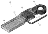
- FIG. 1 is a perspective view of an example test slot.
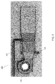
- FIG. 2 is a top view of the example test slot of FIG. 1 .
- FIG. 3 is a bottom view of the example test slot of FIG. 1 .
- FIG. 4 is a perspective view of an example pack of test slots.
- FIG. 5 is a block diagram of an example temperature control system.
- a PCM phase change material
- a PCM includes material that melts or solidifies at certain temperatures.
- heat is absorbed by a PCM when the PCM changes from solid to liquid.
- the heat melts the PCM, turning it into a liquid.
- heat is released by a PCM when the PCM changes from liquid to solid.
- the heat leaves the PCM, allowing the PCM to cool and to solidify.
- Different PCMs may be used for heating and cooling, as described herein.
- a PCM stores thermal energy according to a property called heat of fusion.
- the temperature of the PCM does not change when the PCM is changing state (e.g., melting or solidifying).
- a reason for employing PCMs in the context of the example temperature control systems described herein is to manage a high demand for thermal power (watts) by spreading out energy (joules) demand over time.
- the PCM enables peak demand on a temperature control system by storing thermal energy in the PCM over a relatively long period of time, and then allowing the stored thermal energy from the PCM to be released (heat of fusion) quickly (e.g., at a relatively high power) into a test chamber.
- the PCM thus has a smoothing effect on the peak thermal power demand. In some implementations, this can be achieved without the use of over-capacity heating or cooling systems, thereby reducing test system size and/or cost.
- the example thermal control systems are described in the context of test systems, such as automatic test equipment (ATE).
- the thermal control systems may be used in a test system for testing storage devices, such as solid state drives (SSDs).
- SSDs include devices that use integrated circuit assemblies as memory for persistent storage of data.
- HDDs hard disk drives
- SSDs typically do not include moving mechanical components, such as a spinning magnetic disk.
- the thermal control systems herein are described in the context of an SSD test system, the thermal control systems may be employed in any appropriate context to heat and/or to cool any appropriate system.
- the thermal control systems may be used to control the temperature of an HDD test system, to control the temperature of non-test electronics, and so forth.
- FIGS. 1 to 3 show different views of an example test slot 100 that houses an SSD for testing.
- test slot 100 may be part of a pack (or group) 102 ( FIG. 4 ) of test slots that are serviced by automated machinery, such as one or more robots.
- a robot may move an untested SSD into chamber 103 of test slot 100 .
- the SSD may be tested while in the chamber.
- the robot may move the tested SSD out of the chamber, and replace it with an untested SSD.
- the tests that may be performed on an SSD in the test slot are thermal tests.
- the SSD may be subjected to heating and cooling, and to various rates of heating and cooling.
- the rate of temperature change for heating and/or cooling of the SSD may be between 3° C./minute and 15° C./minute, inclusive (e.g., 3° C./minute, 4° C./minute, 5° C./minute, 6° C./minute, 7° C./minute, 8° C./minute, 9° C./minute, 10° C./minute, 11° C./minute, 12° C./minute, 13° C./minute, 14° C./minute, 15° C./minute). Rates of temperature change other than those listed herein may also be achieved using the systems described herein.
- a thermal control system had to be over-capable. That is, the thermal control system had to have more capacity for heating and/or cooling than would be required to implement a required temperature change for a given device at slower rates. For example, if a relatively high rate of cooling was required, a cooling system had to have a relatively high capacity in relation to the required amount of cooling. In some cases, the capacity could be as much as three times that which would normally be required to achieve the cooling.
- the cooling system may have a capacity that is less than would be required to enable a thermally-conductive structure to reach a specified minimum temperature within a predefined time absent the PCM.
- a heating system had to have a relatively high capacity in relation to the required amount of heating.
- the heating system may have a capacity that is less than would be required to enable the thermally-conductive structure to reach a predefined maximum temperature within a predefined time absent the PCM.
- test slot 100 includes a shroud 105 , an air mover 106 , a thermally-conductive structure 108 , and connections to a heating loop 110 and to a cooling loop 112 .
- connections to heating loop 110 and cooling loop 112 appear broken in FIGS. 1 to 3 , they actually form continuous loops, through which heat transfer liquids pass, as shown, e.g., in FIG. 5 .
- the heating and cooling loops include, respectively, heating and cooling systems, as described herein.
- Air mover 106 may be a blower, fan, or any other appropriate type of device for directing air over a device under test (DUT) in chamber 103 .
- the DUT is an SSD as explained above, however, any appropriate DUT may be used.
- thermally-conductive structure 108 includes one or more metal plates, which conduct thermal energy from either the heating loop 110 or the cooling loop 112 .
- the heating and cooling loops operate out of phase (e.g., they do not operate at the same time).
- thermally-conductive structure 108 either increases in temperature or decreases in temperature. Air from the air mover passes over the thermally-conductive structure, which causes the air to increase or to decrease in temperature. The air then passes through shroud 105 , and over the DUT. The DUT is thus heated, or cooled, to an desired temperature at a desired rate.
- One or more temperature sensors may be placed on, or adjacent to, the DUT in chamber 103 . These temperature sensors may be used to detect, e.g., in real-time, the temperature of, or around, the DUT, and to report that temperature back to a computing device.
- the computing device may include a controller, such as a microprocessor, resident on a circuit board in the test slot.
- the computing device may include a central computer that directs operations of the entire test system, including the operation of multiple slots, robots, feeding stations, and so forth.
- the computing device may be programmed to implement a control loop to regulate operation of the air mover, the heating system, and/or the cooling system based on the temperature detected by the sensors.
- the control loop may include a proportional—integral—derivative controller (PID controller).
- PID controller continuously calculates an error value as a difference between a desired temperature and a detected temperature.
- the controller attempts to reduce (e.g., minimize) that error over time by adjusting a control variable, such as the temperature supplied by the heating cool or the cooling loop (e.g., by adjusting the amount power supplied to the heating or cooling loop).
- a control variable such as the temperature supplied by the heating cool or the cooling loop
- the power to the air mover may be adjusted to increase or to decrease the air flow over the DUT, thereby affecting its temperature.
- FIG. 5 shows an example of a temperature control system 120 that includes PCMs 122 and 124 .
- the temperature control system is configured to maintain a temperature of a PCM in a steady-state condition.
- the PCM changes phase during a transient condition to affect a temperature of a thermally-conductive structure, such as structure 108 of FIG. 1 .
- the steady-state condition is typically longer in duration than the transient condition.
- the transient condition includes a time during which the DUT is to be heated or cooled at specified rates, e.g., between 3° C./minute and 15° C./minute. Temperature changes such as these may occur during testing only and, therefore, are considered transient.
- the steady-state condition includes times between temperature changes required for testing.
- the PCM is thermally charged, as described herein, to enable the PCM to implement, or assist, in cooling or heating that is performed during the transient conditions.
- lower-capacity heating and/or cooling systems may be used than would otherwise be required to implement the same rate of cooling or heating (e.g., the same amount of cooling in a given time).
- temperature control system 120 is configured to actively control a temperature of a liquid passing in proximity to (e.g., through or around) the PCM to enable the thermally-conductive structure to reach a specified temperature during the transient condition.
- Temperature control system 120 includes a cooling loop 112 to cool the one or more test slots.
- the cooling loop includes a first liquid 125 (in a tubing) and a first PCM 124 , with the first PCM for removing heat from the first liquid during a first transient condition.
- the cooling loop also includes a cooling system 126 to cool the first liquid during a first steady-state condition, with the first steady state condition being longer in duration than the first transient condition.
- Temperature control system 120 also includes a heating loop 110 to heat the one or more test slots.
- the heating loop includes a second liquid 130 (in a tubing) and a second PCM 122 , with the second PCM for adding heat to the second liquid during a second transient condition.
- the heating loop includes a heating system 131 to add heat to the second liquid during a second steady-state condition, with the second steady state condition being longer in duration than the second transient condition.
- cooling loop 112 includes tubing to transport liquid to and from a test slot or a pack of test slots in a circulating loop.
- the tubing is made of a thermally-conductive material, such as metal, which permits transmission of heat between the liquid contained therein and PCM 124 .
- the liquid may be any appropriate heat transfer fluid that is capable of extracting heat from PCM 124 , thereby cooling the PCM. In this way, the PCM is thermally charged during the steady-state condition. Examples of heat transfer fluids that may be used include, but are not limited to, water, ethylene glycol, hydrofluoroether (HFE), liquid nitrogen (N 2 ), or appropriate combinations thereof.
- the heat transfer fluid is a mixture of water and ethylene glycol containing 60% ethylene glycol and 40% water.
- the heat transfer fluid may be a mixture of water and ethylene glycol containing 50% ethylene glycol and 50% water, or some other appropriate percentages of water and ethylene glycol.
- the tubing containing the liquid passes proximate to PCM 124 to allow heat transfer to occur between the liquid and the PCM.
- the tubing may pass through the PCM such that the tubing is surrounded by the PCM.
- the liquid in the tubing extracts heat from the PCM.
- the PCM cools and solidifies at its freezing temperature.
- the cooling system cools the liquid (or provides pre-cooled liquid, such as liquid nitrogen).
- the cooled liquid passes through thermally-conductive tubing, which passes in proximity to (e.g., through or around) PCM 124 .
- the cooled liquid extracts heat from the PCM over time, during the steady state condition, eventually causing the PCM to freeze.
- the capacity of the cooling system need not accommodate spikes in demand, such as those which may occur during transient conditions.
- the cooling system can be of lower capacity than would otherwise be required to achieve the spikes in demand that occur during the transient conditions.
- the cooling system may be smaller in size and less costly than cooling systems that have to accommodate spikes in demand that may occur during the transient condition.
- Cooling system 126 may include any appropriate system that is capable of cooling the liquid to a temperature that is sufficient to enable the liquid to absorb heat from the PCM.
- the cooling system may be an active refrigeration system that cools the liquid as it passes through the system.
- the cooling system may include a liquid nitrogen (N 2 ) source, that uses liquid nitrogen as the heat transfer liquid.
- N 2 liquid nitrogen
- the PCM may include hydrated salts or organic compounds that have amounts of heat energy stored in the form of latent heat, which is absorbed or released when the materials change state from solid to liquid or liquid to solid.
- the PCM retains its latent heat without significant change in physical or chemical properties over numerous (e.g., thousands) of cycles.
- Appropriate specific temperature PCM's include PCMs that vary, e.g., between ⁇ 35° C. and +90° C. In an example, PCMs may be used that vary between ⁇ 23° C. and +80° C.
- the PCM may be encapsulated in a polymer, such as polypropylene (PP) or high-density polyethylene (HDPE), or a metal, such as copper or stainless steel.
- the PCM is, or includes, savE® HS 23N.
- This is an inorganic chemical-based PCM having a freezing temperature of ⁇ 23° C.
- This PCM stores thermal energy as latent heat in its crystalline form. On changing phase, the latent heat is released or absorbed, allowing the ambient temperature within the system to be maintained.
- the PCM includes a mix of various salts, additives, and nucleating agents, which allows equilibrium between solid and liquid phases to be attained at the melting point. The PCM continues to absorb heat from the environment while melting, without further increase in temperature.
- tubing from cooling loop 112 is adjacent to (e.g., in contact with) thermally-conductive structure 108 .
- the tubing conducts heat from thermally-conductive structure 108 into the heat transfer liquid contained in the tubing, thereby cooling thermally-conductive structure 108 to an appropriate low (e.g., desired minimum) temperature.
- the cooling loop may be operated in response to a transient condition.
- the transient condition may be that the DUT in the test slot is to be cooled to a specified minimum temperature at a specified rate (e.g., between 3° C./minute and 15° C./minute).
- the cooling loop may be controlled, e.g., by a central computing device, to cause the cooling.
- cooling system 126 may be controlled to cool the heat transfer fluid, and to pump that fluid through the cooling loop.
- the liquid passes in proximity to (e.g., through or around) PCM 124 , which has been previously cooled to its freezing temperature. Heat conducts from the heat transfer fluid to the PCM, thereby cooling the heat transfer fluid. This heat transfer can cause the PCM to melt.
- the PCM maintains its temperature during phase transition, the heat transfer fluid continues to cool.
- the PCM assists the cooling system in cooling the heat transfer fluid, thereby allowing for use of a lower-capacity cooling system than would otherwise be required.
- the PCM reduces peak power demand during the transient condition relative to a peak power demand of the cooling system absent the PCM. That is, in the absence of the PCM, cooling system 126 would have to perform all cooling functions, resulting in higher power consumption than with the PCM.
- heating loop 110 includes tubing to transport liquid to and from a test slot or a pack of test slot in a circulating loop.
- the tubing is made of a thermally-conductive material, such as metal, which permits transmission of heat between the liquid contained therein and PCM 122 .
- the liquid may be any appropriate heat transfer fluid that is capable of transferring heat to PCM 122 , thereby heating the PCM.
- heat transfer fluids include, but are not limited to, water, ethylene glycol, hydrofluoroether (HFE), or appropriate combinations thereof.
- the heat transfer fluid is a mixture of water and ethylene glycol containing 60% ethylene glycol and 40% water.
- the heat transfer fluid may be a mixture of water and ethylene glycol containing 50% ethylene glycol and 50% water, or some other percentages.
- the tubing containing the liquid passes proximate to PCM 122 to allow heat transfer to occur between the liquid and the PCM.
- the tubing may pass through the PCM such that the tubing is surrounded by the PCM.
- the liquid in the tubing imparts heat to the PCM.
- the PCM melts, absorbs heat, and increases in temperature to a target (e.g., maximum) temperature.
- the heating system heats the liquid.
- the heated liquid passes through the thermally-conductive tubing, which passes in proximity to (e.g., through or around) PCM 122 .
- the heated liquid imparts heat to the PCM over time, during the steady state condition, causing the PCM to melt and to maintain a steady-state temperature.
- the capacity of the heating system need not accommodate spikes in demand, such as those which may occur during transient conditions.
- the heating system can be of lower capacity.
- the heating system may be smaller in size and less costly than heating systems that have to accommodate spikes in demand that may occur during the transient condition.
- Heating system 131 may include any appropriate heater or heaters that are capable of heating the liquid to a temperature that is sufficient to enable the liquid to impart heat to the PCM.
- the heating system may include an electrical heater, although other types of heaters may be used.
- the heating system heats the liquid as it passes through the system.
- the PCM may include hydrated salts or organic compounds that have an amount of heat energy stored in the form of latent heat, which is absorbed or released when the materials change state from solid to liquid or liquid to solid.
- the PCM in the heating loop may be different than the PCM in the cooling loop due, at least in part, to the different roles that the two play. That is, the PCM in the cooling loop is brought to a desired minimum temperature, and extracts heat from the heat transfer liquid in order to cool the liquid during transient conditions.
- the PCM in the heating loop is brought to a desired maximum temperature, and imparts heat to the transfer liquid in order to heat the liquid during transient conditions.
- the PCM may be encapsulated in a polymer, such as polypropylene (PP) or high-density polyethylene (HDPE), or a metal, such as copper or stainless steel.
- tubing from heating loop 110 is adjacent to (e.g., in contact with) thermally-conductive structure 108 .
- the liquid in the tubing imparts heat to thermally-conductive structure 108 , thereby heating thermally-conductive structure 108 to an appropriate high (e.g., desired maximum) temperature.
- the heating loop is operated in response to a transient condition.
- the transient condition may be that the DUT in the test slot is to be heated to a specified maximum temperature at a specified rate (e.g., between 3° C./minute and 15° C./minute).
- the heating loop may be controlled, e.g., by a central computing device, to cause the heating.
- heating system 131 may be controlled to heat the heat transfer fluid, and to pump that fluid through the heating loop.
- the liquid passes in proximity to (e.g., through or around) PCM 122 , which has been previously heated to a predefined temperature. Heat transfers from the PCM to the heat transfer fluid, thereby increasing the temperature of the heat transfer fluid.
- This heat transfer away from the PCM can cool the PCM and cause the PCM to solidify.
- the PCM maintains its temperature during phase transition, the heat transfer fluid remains heated.
- the PCM assists heating system 131 in heating the heat transfer fluid, thereby allowing for use of a lower-capacity heating system than would otherwise be required.
- the PCM reduces peak power demand during the transient condition relative to a peak power demand of the heating system absent the PCM. That is, in the absence of the PCM, heating system 131 would have to perform all heating functions, resulting in higher power consumption than with the PCM.
- the temperature control system and variants thereof described herein may be used to control the temperature of a single test slot. In some implementations, the temperature control system and variants thereof described herein may be used to control the temperature of a multiple test slots.
- each test slot in a pack 102 of test slots may have a configuration of the type shown in FIGS. 1 to 3 .
- the temperature of liquid flowing, via tubing, to the different test slots may be controlled by common heating and/or cooling loops.
- a single PCM and cooling system may service multiple test slots, and a single PCM and heating system may service multiple test slots.
- the temperature of liquid flowing, via tubing, to the different test slots may be controlled by slot-dedicated heating and/or cooling loops.
- each test slot may be serviced by a dedicated PCM and cooling system and/or by a dedicated PCM and heating system.
- Testing performed by the example test system described herein may be implemented using hardware or a combination of hardware and software.
- a test system like the ones described herein may include various controllers and/or processing devices located at various points in the system to control operation.
- a central computer may coordinate operation among the various controllers or processing devices.
- the central computer, controllers, and processing devices may execute various software routines to control and coordinate temperature control of one or more test slots using the methods and structures described herein.
- the temperature control system described herein may be controlled by one or more computers, e.g., by sending signals to and from one or more wired and/or wireless connections to each test slot to control each blower, and to control the heating and cooling systems.
- the testing can be controlled, at least in part, using one or more computer program products, e.g., one or more computer program tangibly embodied in one or more non-transitory machine-readable media, for execution by, or to control the operation of, one or more data processing apparatus, e.g., a programmable processor, a computer, multiple computers, and/or programmable logic components.
- a computer program can be written in any form of programming language, including compiled or interpreted languages, and it can be deployed in any form, including as a stand-alone program or as a module, component, subroutine, or other unit suitable for use in a computing environment.
- a computer program can be deployed to be executed on one computer or on multiple computers at one site or distributed across multiple sites and interconnected by a network.
- Actions associated with implementing all or part of the testing can be performed by one or more programmable processors executing one or more computer programs to perform the functions described herein. All or part of the testing can be implemented using special purpose logic circuitry, e.g., an FPGA (field programmable gate array) and/or an ASIC (application-specific integrated circuit).
- FPGA field programmable gate array
- ASIC application-specific integrated circuit
- processors suitable for the execution of a computer program include, by way of example, both general and special purpose microprocessors, and any one or more processors of any kind of digital computer.
- a processor will receive instructions and data from a read-only storage area or a random access storage area or both.
- Elements of a computer may include one or more processors for executing instructions and one or more storage area devices for storing instructions and data.
- a computer will also include, or be operatively coupled to receive data from, or transfer data to, or both, one or more machine-readable storage media, such as mass storage devices for storing data, e.g., magnetic, magneto-optical disks, or optical disks.
- Machine-readable storage media suitable for embodying computer program instructions and data include all forms of non-volatile storage area, including by way of example, semiconductor storage area devices, e.g., EPROM, EEPROM, and flash storage area devices; magnetic disks, e.g., internal hard disks or removable disks; magneto-optical disks; and CD-ROM and DVD-ROM disks.
- semiconductor storage area devices e.g., EPROM, EEPROM, and flash storage area devices
- magnetic disks e.g., internal hard disks or removable disks
- magneto-optical disks e.g., CD-ROM and DVD-ROM disks.
- Any electrical connection involving transfer of signals may imply a direct physical connection or a wired or wireless connection that includes intervening components but that nevertheless allows electrical signals to flow between connected components.
- Any connection of electrical circuitry that enables signals to pass, unless stated otherwise, is an electrical connection and not necessarily a direct physical connection regardless of whether the word electrical is used to modify connection.
Landscapes
- Engineering & Computer Science (AREA)
- Environmental & Geological Engineering (AREA)
- Health & Medical Sciences (AREA)
- Toxicology (AREA)
- Computer Hardware Design (AREA)
- Microelectronics & Electronic Packaging (AREA)
- General Engineering & Computer Science (AREA)
- Physics & Mathematics (AREA)
- General Physics & Mathematics (AREA)
- Testing Of Individual Semiconductor Devices (AREA)
- Control Of Temperature (AREA)
Abstract
Description
Claims (25)
Priority Applications (2)
| Application Number | Priority Date | Filing Date | Title |
|---|---|---|---|
| US15/145,136 US10401423B2 (en) | 2016-05-03 | 2016-05-03 | Thermal control using phase-change material |
| PCT/US2017/026294 WO2017192235A1 (en) | 2016-05-03 | 2017-04-06 | Thermal control using phase-change material |
Applications Claiming Priority (1)
| Application Number | Priority Date | Filing Date | Title |
|---|---|---|---|
| US15/145,136 US10401423B2 (en) | 2016-05-03 | 2016-05-03 | Thermal control using phase-change material |
Publications (2)
| Publication Number | Publication Date |
|---|---|
| US20170322253A1 US20170322253A1 (en) | 2017-11-09 |
| US10401423B2 true US10401423B2 (en) | 2019-09-03 |
Family
ID=60203041
Family Applications (1)
| Application Number | Title | Priority Date | Filing Date |
|---|---|---|---|
| US15/145,136 Active 2036-10-04 US10401423B2 (en) | 2016-05-03 | 2016-05-03 | Thermal control using phase-change material |
Country Status (2)
| Country | Link |
|---|---|
| US (1) | US10401423B2 (en) |
| WO (1) | WO2017192235A1 (en) |
Families Citing this family (2)
| Publication number | Priority date | Publication date | Assignee | Title |
|---|---|---|---|---|
| CN108489841A (en) * | 2018-04-04 | 2018-09-04 | 中国建筑材料科学研究总院有限公司 | A kind of phase-change material cold cycling endurance testing device and test method |
| US11637678B2 (en) * | 2020-10-28 | 2023-04-25 | Qualcomm Incorporated | Determination of geographic ranges in sidelink communications introduction |
Citations (11)
| Publication number | Priority date | Publication date | Assignee | Title |
|---|---|---|---|---|
| US20030062888A1 (en) * | 2001-10-03 | 2003-04-03 | Paul Magliocco | Stackable semiconductor test system and method for operating same |
| US20050200376A1 (en) * | 2004-03-09 | 2005-09-15 | Pak Hong Yee | Integrated circuit (IC) test assembly including phase change material for stabilizing temperature during stress testing of integrated circuits and method thereof |
| US20110267084A1 (en) * | 2010-04-30 | 2011-11-03 | International Business Machines Corporation | Thermal interface material, test structure and method of use |
| KR20120058070A (en) | 2010-11-29 | 2012-06-07 | 홍성기 | Heating system for a vehicle using pcm |
| US20130283827A1 (en) | 2012-03-21 | 2013-10-31 | Delphi Technologies, Inc. | Phase change material evaporator charging control |
| US20140253157A1 (en) * | 2013-03-08 | 2014-09-11 | SMART Storage Systems, Inc. | Test system with localized heating and method of manufacture thereof |
| WO2014202521A1 (en) | 2013-06-20 | 2014-12-24 | Valeo Systemes Thermiques | Element for cooling the air of a motor vehicle |
| US20150003007A1 (en) | 2013-06-28 | 2015-01-01 | Mark MacDonald | Techniques for improved volumetric resistance blower apparatus, system and method |
| KR20150045690A (en) | 2013-10-21 | 2015-04-29 | 이창흠 | Cooling and heating system for refrigeration top car using phase-change material |
| US20160242598A1 (en) * | 2015-02-24 | 2016-08-25 | Ember Technologies, Inc. | Heated or cooled portable drinkware |
| US20170210196A1 (en) * | 2016-01-27 | 2017-07-27 | Ford Global Technologies, Llc | Systems and methods for thermal battery control |
Family Cites Families (1)
| Publication number | Priority date | Publication date | Assignee | Title |
|---|---|---|---|---|
| TWI463334B (en) * | 2012-07-20 | 2014-12-01 | Univ Nat Cheng Kung | Baseline predictive maintenance method for target device and computer program product thereof |
-
2016
- 2016-05-03 US US15/145,136 patent/US10401423B2/en active Active
-
2017
- 2017-04-06 WO PCT/US2017/026294 patent/WO2017192235A1/en active Application Filing
Patent Citations (12)
| Publication number | Priority date | Publication date | Assignee | Title |
|---|---|---|---|---|
| US20030062888A1 (en) * | 2001-10-03 | 2003-04-03 | Paul Magliocco | Stackable semiconductor test system and method for operating same |
| US20050200376A1 (en) * | 2004-03-09 | 2005-09-15 | Pak Hong Yee | Integrated circuit (IC) test assembly including phase change material for stabilizing temperature during stress testing of integrated circuits and method thereof |
| US20110267084A1 (en) * | 2010-04-30 | 2011-11-03 | International Business Machines Corporation | Thermal interface material, test structure and method of use |
| KR20120058070A (en) | 2010-11-29 | 2012-06-07 | 홍성기 | Heating system for a vehicle using pcm |
| US20130283827A1 (en) | 2012-03-21 | 2013-10-31 | Delphi Technologies, Inc. | Phase change material evaporator charging control |
| US20140253157A1 (en) * | 2013-03-08 | 2014-09-11 | SMART Storage Systems, Inc. | Test system with localized heating and method of manufacture thereof |
| WO2014202521A1 (en) | 2013-06-20 | 2014-12-24 | Valeo Systemes Thermiques | Element for cooling the air of a motor vehicle |
| KR20160021452A (en) | 2013-06-20 | 2016-02-25 | 발레오 시스템므 떼르미끄 | Element for cooling the air of a motor vehicle |
| US20150003007A1 (en) | 2013-06-28 | 2015-01-01 | Mark MacDonald | Techniques for improved volumetric resistance blower apparatus, system and method |
| KR20150045690A (en) | 2013-10-21 | 2015-04-29 | 이창흠 | Cooling and heating system for refrigeration top car using phase-change material |
| US20160242598A1 (en) * | 2015-02-24 | 2016-08-25 | Ember Technologies, Inc. | Heated or cooled portable drinkware |
| US20170210196A1 (en) * | 2016-01-27 | 2017-07-27 | Ford Global Technologies, Llc | Systems and methods for thermal battery control |
Non-Patent Citations (5)
| Title |
|---|
| International Preliminary Report on Patentability for PCT/US2017/ 026294, 12 pages (dated Nov. 6, 2018). |
| International Search Report for PCT/US2017/ 026294, 3 pages (dated Jun. 29, 2017). |
| Pluss, savE-HS 23N, Phase Change Material, Technical Data Sheet, 2 pages (Oct. 2012). |
| Pluss, savE—HS 23N, Phase Change Material, Technical Data Sheet, 2 pages (Oct. 2012). |
| Written Opinion for PCT/US2017/ 026294, 11 pages (dated Jun. 29, 2017). |
Also Published As
| Publication number | Publication date |
|---|---|
| US20170322253A1 (en) | 2017-11-09 |
| WO2017192235A1 (en) | 2017-11-09 |
Similar Documents
| Publication | Publication Date | Title |
|---|---|---|
| EP2568790A1 (en) | Apparatus and method | |
| US10146279B2 (en) | Solid state memory thermal regulation | |
| US10401423B2 (en) | Thermal control using phase-change material | |
| US20190041308A1 (en) | Systems, devices, and methods for automated thawing of bag-format storage vessels | |
| CN101975792B (en) | System for testing stability of solid-liquid phase change materials | |
| JP2010535417A5 (en) | ||
| WO2014015099A2 (en) | Data center cooling system | |
| CN108195875B (en) | System and method for rapidly and automatically measuring cold and hot circulation of phase change material in wide temperature area | |
| CN110430715A (en) | The method of controlling electronic devices cooling liquid outlet temperature | |
| Wang et al. | Performance of the capric and lauric acid mixture with additives as cold storage materials for high temperature cooling application | |
| US9939207B2 (en) | Method and apparatus for the pre-conditioning of latent heat storage elements | |
| BR102013017601B1 (en) | DEVICE TO DEFROST A FROZEN BIOLOGICAL MATERIAL | |
| US9976814B2 (en) | Switchably activated heat transfer with magnetic fluid | |
| BR102019009842A2 (en) | method for controlling a road finisher | |
| CN205941417U (en) | Experimental device for be used for testing high low -temperature stability of phase change energy storage material | |
| Saito et al. | On the heat removal characteristics and the analytical model of a thermal energy storage capsule using gelled Glauber's salt as the PCM | |
| US20040139753A1 (en) | Scaled down freezing and thawing system for biopharmaceuticals and biologics | |
| Xu et al. | Thermal characterization of pulsating heat pipes | |
| Pavel et al. | Solidification of a PEG 1500-epoxy nanocomposite around a horizontal pipe | |
| JP2001343197A (en) | Geothermal heat collection test device and method of geothermal heat collection test using the same | |
| Pegg et al. | Cooling equipment for use in cryopreservation | |
| Palomba et al. | Experimental characterization of latent thermal energy storage systems | |
| US11326826B2 (en) | Blast gel pack conditioning equipment | |
| PL416491A1 (en) | Heat energy accumulator and the system with the heat energy accumulator | |
| CN104569031B (en) | For the experimental provision and method of nano-fluid directional solidification |
Legal Events
| Date | Code | Title | Description |
|---|---|---|---|
| AS | Assignment |
Owner name: TERADYNE, INC., MASSACHUSETTS Free format text: ASSIGNMENT OF ASSIGNORS INTEREST;ASSIGNORS:AKERS, LARRY;WRINN, JOSEPH;CAMPBELL, PHILIP;AND OTHERS;SIGNING DATES FROM 20160428 TO 20160502;REEL/FRAME:038895/0827 |
|
| STPP | Information on status: patent application and granting procedure in general |
Free format text: NON FINAL ACTION MAILED |
|
| STPP | Information on status: patent application and granting procedure in general |
Free format text: RESPONSE TO NON-FINAL OFFICE ACTION ENTERED AND FORWARDED TO EXAMINER |
|
| STPP | Information on status: patent application and granting procedure in general |
Free format text: NOTICE OF ALLOWANCE MAILED -- APPLICATION RECEIVED IN OFFICE OF PUBLICATIONS |
|
| STPP | Information on status: patent application and granting procedure in general |
Free format text: PUBLICATIONS -- ISSUE FEE PAYMENT RECEIVED |
|
| STPP | Information on status: patent application and granting procedure in general |
Free format text: AWAITING TC RESP, ISSUE FEE PAYMENT VERIFIED |
|
| STPP | Information on status: patent application and granting procedure in general |
Free format text: PUBLICATIONS -- ISSUE FEE PAYMENT VERIFIED |
|
| STCF | Information on status: patent grant |
Free format text: PATENTED CASE |
|
| AS | Assignment |
Owner name: TRUIST BANK, GEORGIA Free format text: SECURITY INTEREST;ASSIGNOR:TERADYNE, INC.;REEL/FRAME:052595/0632 Effective date: 20200501 |
|
| MAFP | Maintenance fee payment |
Free format text: PAYMENT OF MAINTENANCE FEE, 4TH YEAR, LARGE ENTITY (ORIGINAL EVENT CODE: M1551); ENTITY STATUS OF PATENT OWNER: LARGE ENTITY Year of fee payment: 4 |