US10382139B2 - Polarization pre-coding for a single carrier communication system - Google Patents
Polarization pre-coding for a single carrier communication system Download PDFInfo
- Publication number
- US10382139B2 US10382139B2 US15/386,204 US201615386204A US10382139B2 US 10382139 B2 US10382139 B2 US 10382139B2 US 201615386204 A US201615386204 A US 201615386204A US 10382139 B2 US10382139 B2 US 10382139B2
- Authority
- US
- United States
- Prior art keywords
- polarization
- carrier transmission
- receiver
- matrix
- polarized
- Prior art date
- Legal status (The legal status is an assumption and is not a legal conclusion. Google has not performed a legal analysis and makes no representation as to the accuracy of the status listed.)
- Active, expires
Links
Images


Classifications
-
- H—ELECTRICITY
- H04—ELECTRIC COMMUNICATION TECHNIQUE
- H04B—TRANSMISSION
- H04B10/00—Transmission systems employing electromagnetic waves other than radio-waves, e.g. infrared, visible or ultraviolet light, or employing corpuscular radiation, e.g. quantum communication
- H04B10/50—Transmitters
- H04B10/516—Details of coding or modulation
- H04B10/532—Polarisation modulation
-
- H—ELECTRICITY
- H04—ELECTRIC COMMUNICATION TECHNIQUE
- H04B—TRANSMISSION
- H04B14/00—Transmission systems not characterised by the medium used for transmission
- H04B14/002—Transmission systems not characterised by the medium used for transmission characterised by the use of a carrier modulation
- H04B14/008—Polarisation modulation
-
- H—ELECTRICITY
- H04—ELECTRIC COMMUNICATION TECHNIQUE
- H04B—TRANSMISSION
- H04B7/00—Radio transmission systems, i.e. using radiation field
- H04B7/02—Diversity systems; Multi-antenna system, i.e. transmission or reception using multiple antennas
- H04B7/04—Diversity systems; Multi-antenna system, i.e. transmission or reception using multiple antennas using two or more spaced independent antennas
- H04B7/0413—MIMO systems
- H04B7/0417—Feedback systems
-
- H—ELECTRICITY
- H04—ELECTRIC COMMUNICATION TECHNIQUE
- H04B—TRANSMISSION
- H04B7/00—Radio transmission systems, i.e. using radiation field
- H04B7/02—Diversity systems; Multi-antenna system, i.e. transmission or reception using multiple antennas
- H04B7/04—Diversity systems; Multi-antenna system, i.e. transmission or reception using multiple antennas using two or more spaced independent antennas
- H04B7/06—Diversity systems; Multi-antenna system, i.e. transmission or reception using multiple antennas using two or more spaced independent antennas at the transmitting station
- H04B7/0613—Diversity systems; Multi-antenna system, i.e. transmission or reception using multiple antennas using two or more spaced independent antennas at the transmitting station using simultaneous transmission
- H04B7/0615—Diversity systems; Multi-antenna system, i.e. transmission or reception using multiple antennas using two or more spaced independent antennas at the transmitting station using simultaneous transmission of weighted versions of same signal
- H04B7/0619—Diversity systems; Multi-antenna system, i.e. transmission or reception using multiple antennas using two or more spaced independent antennas at the transmitting station using simultaneous transmission of weighted versions of same signal using feedback from receiving side
- H04B7/0621—Feedback content
- H04B7/0626—Channel coefficients, e.g. channel state information [CSI]
-
- H—ELECTRICITY
- H04—ELECTRIC COMMUNICATION TECHNIQUE
- H04B—TRANSMISSION
- H04B7/00—Radio transmission systems, i.e. using radiation field
- H04B7/02—Diversity systems; Multi-antenna system, i.e. transmission or reception using multiple antennas
- H04B7/10—Polarisation diversity; Directional diversity
Definitions
- the present invention in some embodiments thereof, relates to a polarized single carrier communication system and, more particularly, but not exclusively, to a dual polarization single carrier communication link operating in a Non-Line-Of-Sight (NLOS) mode.
- NLOS Non-Line-Of-Sight
- Polarized transmission is commonly used, and polarized reception is used to receive the polarized transmission.
- a polarized signal may be rotated or the polarization may become less pronounced, by atmospheric conditions, which come and go.
- None-line-of-sight (NLOS) polarized transmissions may also be affected by objects in the environment, such as lakes and/or buildings.
- An aspect of the invention relates to determining a transmission polarization by setting coefficients for transmitter pre-coders.
- Such a scheme for determining polarization potentially provides several benefits: the polarization can change dynamically, potentially following dynamically changing meteorological conditions and/or other changes in the environment, such as new buildings, floods, etc.
- An aspect of the invention relates to determining transmission polarization based on feedback of signal quality from a receiver, potentially optimizing polarization of a transmitted signal and/or transmitted signals in a dual polarization system to improve reception quality, communication throughput or other figures of merit.
- An aspect of the invention relates to splitting data between transmission polarizations based on feedback of signal quality from a receiver, potentially optimizing splitting the data among polarizations to improve total communication rate.
- a method for optimizing reception of a polarized single-carrier transmission including transmitting a polarized single-carrier transmission to a receiver, receiving feedback from the receiver of a figure of merit of the polarized single-carrier transmission, and electronically changing polarization of the polarized single-carrier transmission based on the feedback.
- the changing polarization is performed by multiplying a vector T, of values to be transmitted, by a rotation matrix D.
- the polarized single-carrier transmission includes a single stream of data transmitted at a specific polarization.
- the polarized single-carrier transmission includes a two streams of data transmitted at two different polarizations.
- Singular Value Decomposition Singular Value Decomposition
- the changing polarization of the polarized single-carrier transmission based on the feedback includes multiplying values to be transmitted, represented by a vector T, by a matrix P, where
- the changing polarization of the polarized single-carrier transmission based on the feedback includes multiplying values to be transmitted, represented by a vector T, by a matrix P, where
- ⁇ P _ _ ( cos ⁇ ( ⁇ ) ⁇ e i ⁇ ⁇ ⁇ sin ⁇ ( ⁇ ) ⁇ e i ⁇ ⁇ ⁇ - sin ⁇ ⁇ ( ⁇ ) cos ⁇ ( ⁇ ) )
- ⁇ tan ⁇ ( 2 ⁇ ⁇ ) - 2 ⁇ ( Re ⁇ ⁇ h 11 * ⁇ h 12 ⁇ e - i ⁇ ⁇ ⁇ + Re ⁇ ⁇ h 21 * ⁇ h 22 ⁇ e - i ⁇ ⁇ ⁇ ) ( ⁇ h 11 ⁇ 2 - ⁇ h 12 ⁇ 2 + ⁇ h 21 ⁇ 2 - ⁇ h 22 ⁇ 2 )
- ⁇ is an angle by which the polarization is rotated
- ⁇ is a measure of mixing of perpendicular components
- h ij is a component of a channel matrix H.
- the changing polarization of the polarized single-carrier transmission based on the feedback includes multiplying values to be transmitter represented by a vector T, by a matrix P
- the values of ⁇ and ⁇ are set iteratively, such that for iteration n
- ⁇ ( n ) ⁇ ( n - 1 ) - ⁇ ⁇ ⁇ sign ⁇ ⁇ r 1 ( n ) ⁇ sin ⁇ ( ⁇ 1 ( n ) ) + r 1 ( n ) ⁇ sin ⁇ ( ⁇ 2 ( n ) ) ⁇ sign ⁇ ⁇ r 1 ( n ) ⁇ cos ⁇ ( ⁇ 1 ( n ) ) + r 2 ( n ) ⁇ cos ⁇ ( ⁇ 2 ( n ) ) ⁇
- ⁇ ( n ) ⁇ ( n - 1 ) - ⁇ ⁇ ⁇ sign ⁇ ⁇ Re ⁇ ⁇ h 11 * ( n ) ⁇ h 12 ( n ) ⁇ e i ⁇ ⁇ ⁇ ⁇ ( n ) ⁇ + Re ⁇ ⁇ h 21 * ( n ) ⁇ h 22 ( n ) ⁇ e - i
- ⁇ is a step size of the value ⁇
- ⁇ is a step size of the value ⁇
- ⁇ and ⁇ receive initial values, (b) multiplying the vector T by the matrix P, (c) at the receiver separating components of a received signal, (d) evaluating quality measures of each one of the separated components, (e) providing the quality measures as input to a search method, (f) updating at least one of ⁇ and ⁇ .
- the transmitting a polarized single-carrier transmission to the receiver includes transmitting over a None-Line-Of-Sight channel.
- a single-carrier communication transmitter including a source for a polarized single-carrier transmission signal, a circuit for receiving feedback from a receiver describing a figure of merit of a received polarized single-carrier transmission, and a circuit for changing polarization of the polarized single-carrier transmission signal, based on the feedback.
- a single-carrier communication system including a receiver for receiving a polarized single-carrier transmission signal, including a circuit for determining a figure of merit of the received polarized single-carrier transmission signal, and a circuit for transmitting feedback including data describing the figure of merit, and a transmitter including a circuit for receiving the feedback from the receiver, a source for a polarized single-carrier transmission signal, a circuit for changing polarization of the polarized single-carrier transmission signal, based on the feedback, producing a changed polarization single-carrier transmission signal, and a circuit for transmitting the changed polarization single-carrier transmission signal to the receiver.
- Implementation of the method and/or system of embodiments of the invention can involve performing or completing selected tasks manually, automatically, or a combination thereof. Moreover, according to actual instrumentation and equipment of embodiments of the method and/or system of the invention, several selected tasks could be implemented by hardware, by software or by firmware or by a combination thereof using an operating system.
- a data processor such as a computing platform for executing a plurality of instructions.
- the data processor includes a volatile memory for storing instructions and/or data and/or a non-volatile storage, for example, a magnetic hard-disk and/or removable media, for storing instructions and/or data.
- a network connection is provided as well.
- a display and/or a user input device such as a keyboard or mouse are optionally provided as well.
- FIG. 1 is a simplified drawing of None Line Of Sight (NLOS) communication links
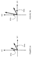
- FIGS. 2A-C are simplified illustrations of three instances of received signals which were transmitted polarized along vertical and horizontal axes;
- FIGS. 3A-B are simplified illustrations of two instances of received signals which were transmitted polarized along vertical and horizontal axes;
- FIG. 4 is a simplified flow chart illustration of a method for optimizing reception of a polarized single-carrier transmission according to an example embodiment of the invention
- FIG. 5 is a simplified illustration of a single-carrier communication transmitter according to an example embodiment of the invention.
- FIG. 6 is a simplified illustration of a single-carrier communication system according to an example embodiment of the invention.
- FIG. 7 is a simplified block diagram illustration of an example embodiment of the invention.
- FIG. 8 is a simplified illustration of a data frame including preamble symbols and data symbols according to an example embodiment of the invention.
- FIG. 9A is a graph of a cross-correlation between a preamble symbol sequence S 1 and a corresponding symbol sequence P 1 used by a receiver according to an example embodiment of the invention.
- FIG. 9B is a graph of a cross correlation between a preamble symbol sequence S 2 and a symbol sequence P 1 according to an example embodiment of the invention.
- FIG. 10 is a simplified example of an NLOS channel, according to an example embodiment of the invention.
- FIG. 11 is a simplified schematic illustration of structure of a pre-coder according to an example embodiment of the invention.
- FIG. 12 is a simplified flow chart illustration of using a search method for finding a pre-coding matrix according to an example embodiment of the invention.
- FIG. 13A is a simplified schematic illustration of structure of a pre-coder implementing a filtering according to an example embodiment of the invention
- FIG. 13B is a simplified line drawing illustration of an example embodiment which may be used to construct the filter of FIG. 13A according to an example embodiment of the invention.
- FIG. 14 is a simplified flow chart illustration of a method for obtaining coefficients for pre-coding filters according to an example embodiment of the invention.
- the present invention in some embodiments thereof, relates to a polarized single carrier communication system and, more particularly, but not exclusively, to a polarized single carrier communication link operating in a Non-Line-Of-Sight (NLOS) mode.
- NLOS Non-Line-Of-Sight
- polarized communication system in all its grammatical forms is used throughout the present specification and claims to mean a communication system that uses one or more polarizations to communicate.
- Cellular backhaul systems in microwave and millimeter waves are required to provide high availability throughout the year. They are therefore regulated in order to avoid interference, and are carefully positioned and steered during installation.
- dual polarization (vertical and horizontal) systems are employed in order to double the capacity per link.
- a common practice includes aligning the polarization axes at both ends of the link. Such a process adds to the complexity of the installation.
- the two polarized signals may mix with each other even in line-of-site (LOS) scenarios due to atmospheric events such as rain storms and due to imperfect antennas.
- the mixture might not be symmetric, that is, one polarization might be “contaminated” by the other to a different extent than the contamination of the other polarization.
- the amount of H-polarized signal that is received as a V polarization may be 5 dB higher than the amount of V-polarized signal that is received as H polarization.
- An aspect of the invention relates to transmitting a polarized transmission in a polarization angle which improves quality and/or data transmission capacity of the transmission.
- An aspect of the invention relates to performing polarized transmission between a transmitting antenna and a receiving antenna.
- the polarization direction is optionally not simply set to be vertical and/or horizontal, but set to be at some specific angle, such as by measuring quality of the communication link and selecting a direction which improves quality.
- the quality is optionally measured dynamically, over time, and the polarization direction is optionally changed over time.
- the quality is optionally measured by measuring some quality measure of a received signal at the receiver.
- An aspect of the invention relates to determining optimal polarization(s) to use in transmission.
- signals in two different polarizations are transmitted, a communication channel is characterized, and an optimal polarization(s) is determined.
- two polarizations are transmitted, and the communication channel is characterized to find the optimal polarization.
- searching for an optimal polarization in a single polarization system is optionally performed by varying the polarization until an optimal performance is achieved.
- An aspect of the invention relates to performing transmission polarization by setting coefficients for transmitter pre-coders.
- Such polarization potentially provides several benefits: the polarization can change dynamically, potentially following dynamically changing meteorological conditions and/or other changes in the environment, such as new buildings, floods, etc.
- An aspect of the invention relates to performing transmission polarization based on feedback of signal quality from a receiver, potentially optimizing polarization of a transmitted signal to improve reception.
- An aspect of the invention relates to dividing data bandwidth between transmission polarizations based on feedback of signal quality from a receiver, potentially optimizing dividing the data bandwidth among polarizations to improve total bandwidth.
- An aspect of the invention relates to characterizing an effect (H) of a communication link, or communication channel, on a transmitted signal (T), producing a received signal (R).
- FIG. 1 is a simplified drawing of None Line Of Sight (NLOS) communication links.
- NLOS non-line-of-sight
- FIG. 1 depicts a base station antenna 101 , communicating via a first communication link 105 with a small cell antenna 102 a , and via a second communication link 104 with a small cell antenna 102 b .
- first communication link 105 reflection, for example off a building, occurs.
- second communication link 104 diffraction, for example between buildings, occurs.
- NLOS links may increase the mixing between different polarizations. Several cases of polarization mixing are described below with reference to FIGS. 2A-C .
- FIGS. 2A-C are simplified illustrations of three instances of received signals which were transmitted polarized along vertical and horizontal axes.
- FIGS. 2A-C depicts vertically polarized signals 203 a 203 b 203 c and horizontally polarized signals 204 a 204 b 204 c against a vertical axis 202 and a horizontal axis 201 .
- FIG. 2A demonstrates no polarization rotation, that is, the horizontally polarized signals 204 a is received along the horizontal axis 201 and the vertically polarized signals 203 a is received along the vertical axis 202 .
- FIG. 2B demonstrates a constructive polarization rotation, where each of the transmitted signals 203 b 204 b is received partly in a horizontal polarization and partly in a vertical polarization; however, the received signals 203 b 204 b remain orthogonal to each other.
- FIG. 2C demonstrates a destructive polarization rotation in which the received signals 203 c 204 c are not orthogonal to each other.
- SNR signal-to-noise-ratio
- Each of the different polarization signals may arrive at a different power level. Such a situation is demonstrated in FIGS. 3A-B .
- FIGS. 3A-B are simplified illustrations of two instances of received signals which were transmitted polarized along vertical and horizontal axes.
- FIGS. 3A-B depict vertically polarized signals 303 a 303 b and horizontally polarized signals 304 a 304 b against a vertical axis 302 and a horizontal axis 301 .
- FIG. 3A demonstrates a destructive polarization rotation in which the received signals 303 a 304 a are not orthogonal to each other, yet are received by a receiver at approximately equal power.
- FIG. 3B demonstrates a destructive polarization rotation in which the received signals 303 b 304 B are not orthogonal to each other, and are received by a receiver at different powers.
- polarization mixing may depend on frequency, in other words, polarization mixing may be dispersive. Different frequency components of transmitted signals may undergo different polarization mixing, especially in NLOS conditions.
- wireless links and specifically NLOS links, are dynamic in nature. They tend to change over time in response to weather and season changes and environmental development.
- a less favorable polarization direction may be so weak that it may be preferable to avoid using the less favorable polarization direction, for example so as not to interfere with communications along the more favorable polarization direction.
- FIG. 4 is a simplified flow chart illustration of a method for optimizing reception of a polarized single-carrier transmission according to an example embodiment of the invention.
- the method of FIG. 4 includes:
- the feedback from the receiver includes a channel response matrix
- the changing polarization of the polarized single-carrier transmission includes calculating the matrix H defined in Equation 2 below, and calculating matrix D based on the matrix H .
- FIG. 5 is a simplified illustration of a single-carrier communication transmitter 500 according to an example embodiment of the invention.
- FIG. 5 depicts the single-carrier communication transmitter 500 which includes a source 502 for a polarized single-carrier transmission signal 505 ; a circuit 504 for receiving feedback 503 from a receiver (not shown) providing figure of merit for channel which carries the polarized single-carrier transmission signal; and a circuit 506 for changing polarization of the polarized single-carrier transmission signal 505 , based on the feedback 503 , producing a polarized and optionally rotated single-carrier transmission signal 507 .
- FIG. 6 is a simplified illustration of a single-carrier communication system 600 according to an example embodiment of the invention.
- FIG. 6 depicts:
- a receiver 602 for receiving a polarized single-carrier transmission signal 601 , including a circuit 604 for determining quality of the received polarized single-carrier transmission signal 601 ; and a circuit 606 for transmitting feedback 607 comprising data describing the quality,
- a transmitter 610 including a circuit 612 for receiving the feedback 607 from the receiver 602 ; a source 614 for a polarized single-carrier transmission signal 615 ; a circuit 616 for changing polarization of the polarized single-carrier transmission signal 615 , based on the feedback 607 , producing a changed polarization single-carrier transmission signal 617 ; and a circuit 618 for transmitting the changed polarization single-carrier transmission signal 601 to the receiver 602 .
- the a circuit 604 calculating the matrix H defined in Equation 2 below, and calculating matrix D based on the matrix H , the feedback 607 includes the matrix H , the circuit 616 for computes the matrix D based on the feedback 607 , and produces the changed polarization single-carrier transmission signal 617 using the matrix D.
- An aspect of the invention relates to splitting data to be transmitted among two transmitted signals, each of which has a different polarization. Therefore, the stream of data is first split into two streams, and a polarization pre-coder mixes the two streams among two transmission polarizations. Feedback from a receiver optionally provides information about a polarization-dependent impulse response or frequency response of the communication channel, as well as information about the supported communication rate, for each one of the data streams/polarizations.
- FIG. 7 is a simplified block diagram illustration of an example embodiment of the invention.
- FIG. 7 depicts a transmitter and a receiver using pre-coding filters to determine polarization angles of transmitted signals according to an example embodiment of the invention.
- a transmitter 701 receives a stream of data 702 to be transmitted is split by a multi radio interface 704 into two streams 706 a 706 b .
- the splitting may be implemented, by way of a non-limiting example, as described in U.S. Pat. No. 8,804,763 titled “Transmission of Data over Parallel Links”.
- Each of the streams 706 a 706 b is modulated and coded separately by a modulator and coder 708 a 708 b according to an allowable communication rate as received from a receiver 721 .
- Implementation may be carried out, by way of a non-limiting example, as described in U.S. Pat. No. 8,416,693, “Errorless and Hitless Variable Data Rate Communication.”
- the two streams 706 a 706 b are arranged in frames and padded periodically by unique sequences of symbols, producing output of two streams 709 a 709 b .
- Each stream 709 a 709 b has its own unique sequence 707 a 707 b ).
- the sequences 707 a 707 b are referred to as preamble sequences.
- the sequences 707 a 707 b may optionally be identified by receiver(s) and may be used by the receiver(s) to estimate an impulse response of the channel.
- the frames are optionally synchronized in time such that both preamble sequences 707 a 707 b are transmitted simultaneously.
- the streams 709 a 709 b are fed into a pre-coding filters unit 710 , which optionally determines the polarization of the streams, producing polarized signals 711 a 711 b .
- the polarized signals 711 a 711 b are fed to transmitters 712 a 712 b for each one of the polarizations, and from there to antennas 714 a 714 b , which transmit polarized signals 715 a 715 b to the receiver 721 .
- the receiver 721 receives the transmitted polarized signals 715 a 715 b at antennas 722 a 722 b , which pass the received signals to down-converters 724 a 724 b .
- the down-converters 724 a 724 b produce output of baseband I and Q signals 725 a 725 b , which enters a unit 726 for producing feedback which may optionally be used for updating the pre-coding filters in the pre-coding filters unit 710 .
- the unit 726 for producing feedback optionally produces the feedback based on received preamble sequences, and optionally calculates a quality measure of the communication channel, either as a total of the two polarizations, or for each polarization separately.
- An arrow 727 depicts the optional feedback, although the feedback is actually part of data transmitted from the receiver 721 to the transmitter 701 , and not necessarily a direct connection between the unit 726 in the receiver 721 and the pre-coding filters unit 710 in the transmitter 710 .
- the signals 725 a 725 b are also passed to a unit 730 containing adaptive filters, which optionally performs zero-forcing as described elsewhere herein.
- the unit 730 containing adaptive filters produces output signals 731 a 731 b , which enters units 732 a 732 b , which decode the output signals 731 a 731 b and optionally produce feedback 733 a 733 b for updating an ACM (Adaptive Coding and Modulation) profile of the transmitter 701 .
- the feedback 733 a 733 b is transmitted to the transmitter 701 , for optional use by the modulator and coder 708 a 708 b .
- the feedback 733 a 733 b is actually part of data transmitted from the receiver 721 to the transmitter 701 .
- FIG. 8 is a simplified illustration of a data frame 800 including preamble symbols 802 and data symbols 804 according to an example embodiment of the invention.
- FIG. 8 demonstrates the frame 800 structure, with preamble symbols 802 at a beginning of the frame, data symbols 804 following, followed by preamble symbols 806 of a next frame 808 .
- the preamble symbol sequences may be selected as described in U.S. Pat. No. 9,203,484 titled “Using Sequences for Symbol Timing Synchronization in Single-Carrier MIMO Communication Systems”.
- FIG. 9A is a graph 900 of a cross-correlation between a preamble symbol sequence S 1 and a corresponding symbol sequence P 1 used by a receiver according to an example embodiment of the invention.
- the graph 900 has an X-axis 901 depicting time, and a Y-axis 902 depicting magnitude of correlation values.
- a line 903 depicts the cross-correlation between S 1 and P 1 .
- the correlation values are discrete in time, and the line 903 depicted in FIG. 9A is a line which passes approximately through the symbol values.
- FIG. 9B is a graph 910 of a cross correlation between a preamble symbol sequence S 2 and a symbol sequence P 1 according to an example embodiment of the invention.
- the graph 910 has an X-axis 901 depicting time, and a Y-axis 902 depicting magnitude of symbol values.
- a line 913 depicts the cross-correlation between S 2 and P 1 .
- the correlation values are discrete, and the line 913 depicted in FIG. 9B is a line which passes approximately through the symbol values.
- FIGS. 9A and 9B demonstrate that it is possible to estimate an impulse response of a channel between a transmitter transmitting a preamble sequence S 1 and a receiver which performs a correlation with P 1 , while eliminating interference from a sequence S 2 .
- we may estimate an impulse response between a transmitter transmitting S 2 for example on a differently polarized signal, and the receiver.
- one or more of the following technical features are maintained for estimating impulse response of a dual-polarization channel at a receiving side.
- the graphs 900 910 in FIGS. 9A-9B demonstrate estimating an impulse response of a channel between a transmitter of a preamble sequence S 1 and a receiver which performed correlation with a symbol sequence P 1 , while eliminating interference by sequence S 2 .
- an impulse response between a transmitter of a preamble symbol sequence S 2 and a receiver may be estimated.
- a channel matrix can be modeled as having unity gain elements with different phases.
- impulse response data includes information about gain as well as shape of the channel.
- a channel described herein connects signals in two polarizations at the transmission side with signals in two polarizations in the receiving side. It is noted that in some embodiments a channel may connect a signal in one polarization at the transmission side with a signal in one polarization in the receiving side, which is a reduction of the above two-polarization example which a person skilled in the art will understand.
- the two polarizations need not necessarily be vertical and horizontal polarizations. They can be directed along diagonals. Moreover, the two polarizations need not be linear polarizations. The two polarizations may be right circular and left circular polarizations, or even more generally—right elliptic and left-elliptic polarizations. Finally, the two polarizations need not be orthogonal, as long as the two polarizations span a two dimensional polarization-space.
- a channel in general may depend on frequency.
- a first assumption is that the dependence is weak, or alternatively, that the channel is narrow band and as such variations with frequency may be neglected. Later on a description will be provided which does depend on frequency.
- a channel may be represented as a matrix connecting a two dimensional transmit vector with a two-dimensional receive vector.
- Equation 1 the subscripts V and H denote as an example two polarization vectors (Vertical and Horizontal).
- the Matrix H defines the channel.
- T V and T H Transmitted values are denoted by T V and T H .
- T V and T H are assumed to have identical power levels. This assumption is often true due to the fact that there is typically a limitation on the transmitted power of the individual signals and not on a sum of the power of the individual signals.
- Additive noise terms are denoted by n v and n h , and are optionally, by way of a non-limiting example, unity-variance independent Gaussian terms.
- Received values are denoted by R v and R h correspondingly.
- U and V are rotation matrices and D is a diagonal matrix with singular values as follows:
- the parameters ⁇ square root over ( ⁇ 1 ) ⁇ and ⁇ square root over ( ⁇ 2 ) ⁇ are the singular values of the channel matrix, or equivalently, the eigenvalues of H T H .
- the covariance matrix of the noise can be expressed as:
- Equation 8 An implication of Equation 8 demonstrated with the following example, depicted in FIG. 10 .
- FIG. 10 is a simplified example of an NLOS channel, according to an example embodiment of the invention.
- FIG. 10 depicts a transmission from a transmitter 1002 to a receiver 1004 , via an NLOS channel 1006 which, by dint of reflection and polarization rotation off a building 1010 , and a different attenuation for different polarizations by dint of passing over a lake 1012 .
- V _ H 1 2 ⁇ ( 1 1 1 - 1 ) .
- Effect of the different attenuation for different polarizations may be described by multiplication of a transmitted signal by the following: ⁇ 1 ⁇ 2 .
- Equation 8a implies that if either of the singular values ⁇ square root over ( ⁇ 1 ) ⁇ or ⁇ square root over ( ⁇ 2 ) ⁇ is very small, the noise variance for both polarizations becomes very large. This may not be a desirable situation.
- FIG. 10 demonstrates that in some embodiments there may be motivation for separating the communication into two polarizations in a way that if one polarization is attenuated, the attenuated polarization transmission does not adversely affect reception the other polarization, or minimally affects reception the other polarization.
- optimization may take into consideration a frequency-dependent channel matrix H .
- power transmitted in each polarization is limited separately. It is noted that limiting power separately in each polarization is a common case in wireless backhaul scenarios.
- One or more of the above communication management goals are potentially be achieved by introducing a polarization pre-coder as detailed below.
- Transmitted values T are a linear combination of data values expressed as a two-dimensional vector X .
- data values are assumed to be independent and have an equal power level.
- the pre-coding matrix is a rotation matrix, and more specifically, the matrix V associated with a SVD of the channel matrix, as shown in Equation 3.
- P V Equation 10
- a rotation matrix maintains power at each polarization component, and potentially assists in complying with a power limitation requirement.
- rotation and scaling are applied to a received vector by multiplication with a matrix D ⁇ 1 U H , which is associated with the SVD of the channel matrix.
- the multiplication corresponds to applying a zero-forcing receiver.
- Equation 13 implies that the two data values are contaminated by uncorrelated noise elements, each of which may have a different variance.
- the first data value is immersed in noise with variance of 1/ ⁇ 1 and the second data value is immersed in noise with variance of 1/ ⁇ 1 .
- Equation 13 teaches a solution which separates mutual dependence that was shown in Equation 8a.
- different noise levels potentially imply that each of the data values be modulated differently.
- the modulation and coding may be adapted to fit the noise level.
- the modulator and coder 708 a 708 b blocks potentially produce communication rates which are adapted to noise levels of the channel.
- the pre-coding filters unit 710 performs rotation at the transmitting side, and the adaptive filters unit 730 performs the zero-forcing at the receiving side.
- FIG. 11 is a simplified schematic illustration of structure of a pre-coder according to an example embodiment of the invention.
- FIG. 11 depicts an example electronic circuitry which can implement multiplying input signals represented by a two-valued vector X by a four valued matrix P, producing a transmission signal represented by a two-valued vector T.
- FIG. 11 shows a pre-coder circuit.
- Two input signals X 1 1101 a and X 2 1101 b are fed into multipliers P 11 1102 a , P 21 1102 b , P 12 1102 c , P 22 1102 d , which are signal multiplying circuits.
- the signals X 1 1101 a and X 2 1101 b are multiplied by parameters set dynamically in the multipliers P 11 1102 a , P 21 1102 b , P 12 1102 c , P 22 1102 d , the parameters optionally corresponding to values of a pre-coder matrix P.
- Four output signals 1104 a 1104 b 1104 c 1104 d are produced by the four multipliers P 11 1102 a , P 21 1102 b , P 12 1102 c , P 22 1102 d . Pairs of the output signals 1104 a 1104 b 1104 c 1104 d are added by signal adders 1106 a 1106 b , producing output of two signals T 1 1108 a and T 2 1108 b.
- the output signals T 1 1108 a and T 2 1108 b correspond to a result of the input signals X 1 1101 a and X 2 1101 b being multiplied by a pre-coder matrix P.
- Equation 13 The equations as developed above, up to Equation 13, show that at a specific rotation, two polarization transmissions may be isolated from each other.
- the pre-coding matrix canceled the rotation at the first reflection point.
- the pre-coding matrix actually rotated the signal in the opposite direction.
- the covariance matrix is as in Equation 13 instead of as in the first row of the equations in Equation 8.
- Equation 13 it is desired to have a covariance matrix like in Equation 13, which potentially enables a higher communication rate, and a pre-coder is optionally used to cancel some of the rotations in the channel.
- ⁇ corresponds to a rotation angle
- ⁇ corresponds to a mixing of a signal of one polarization signal with a signal of another polarization.
- the channel matrix H is estimated at a receiving side.
- Equation 16 corresponds to element 1,2 of the rotation matrix, which one optionally strives to be zero, as in Equation 15.
- Equation 16 A solution ( ⁇ , ⁇ ) which zeros the expression in Equation 16 is given by:
- Equation 17 provides values for ⁇ and ⁇ for a known channel matrix. Once the values of ⁇ and ⁇ are calculated, the values of ⁇ and ⁇ may optionally be used in Equation 14 in implementing a pre-coder as depicted in FIG. 11 .
- Equation 17 provides an exact solution to finding parameters for a zero-forcing pre-coder.
- a solution may be implemented using an iterative method.
- Equation 17 As a non-limiting example of an iterative solution we have the following set of update equations which are derived from Equation 17.
- n indicates an iteration number.
- methods for finding a pre-coding matrix for communication with dual polarization over an NLOS channel used calculations of eigen-vectors.
- a search method is performed to find the pre-coding matrix.
- the rotation matrix shown in Equation 14 has two parameters, a and cp. Search may be optionally performed for each one of ⁇ and ⁇ independently, or for both simultaneously.
- Well known search methods such as the Nelder-Mead method may be used to search for parameters which increase or maximize quality parameters such as, by way of a non-limiting example, a communication rate, a sum SNR in dB (of both polarizations), or some other quality criterion.
- FIG. 12 is a simplified flow chart illustration of using a search method for finding a pre-coding matrix according to an example embodiment of the invention.
- the method of FIG. 12 includes:
- separating received polarized signals and evaluating a quality criterion ( 1206 ), such as, by way of a non-limiting example, sum SNR in dB of the two separated received polarized signals, or some other quality criterion;
- An optimal rotation matrix as described by Equation 14 optionally transmits one stream of data along a best polarization of the channel, and another stream of data along a worst polarization of the channel.
- Such transmission theoretically provides a highest total capacity (or sum SNR in dB).
- Such transmission also implies that one stream of data will have a relatively very high SNR, and the other—a relatively low SNR.
- a communication system may not always be able to take advantage of the relatively very high SNR or the relatively low SNR.
- the high SNR may optionally be decreased, and the low SNR may optionally be increased.
- the following pre-coding matrix may optionally be used:
- Equation 18a is similar to Equation 14 with an additional parameter ⁇ .
- a potential benefit of using such a pre-coding matrix is that the pre-coding matrix enables splitting total transmitted power unevenly between the two streams. At the same time transmitted power per polarization does not change.
- a power gain of the first stream is ⁇ cos 2 ( ⁇ )+sin 2 ( ⁇ + ⁇ ), while the power gain of the second stream is cos 2 ( ⁇ + ⁇ )+sin 2 ( ⁇ ).
- the gains are generally different, and potentially enable taking some power from one stream and giving it to the other.
- Finding an optimal value of ⁇ may optionally be done using the search method presented in the above section titled “A search method for finding a pre-coding matrix”.
- the method requires two steps:
- This term optimal pre-coding matrix is used in a sense of maximizing mutual information between a transmitter and a receiver, under a constraint that the total transmitted power (or both polarizations) is limited.
- mutual information is a term from the field of information theory.
- the term denotes an amount of information we can learn about transmitted data from received data for a given modulation scheme and a channel, e.g. 256 QAM with a Gaussian noise of some power.
- Determining and/or using a rotation matrix that maximizes the mutual information means that we can learn more information about the transmitted data from the received data. When measuring in bits, this implies we can transmit more bits of information.
- Equation 19 P H P and P is the notation for the pre-coding matrix; and ⁇ denotes the channel SNR.
- a limitation on the trace (tr(Q)) guarantees that the pre-coding matrix does not amplify total transmitted power.
- the matrix S is diagonal. Finding a Q that maximizes mutual information is equivalent to finding S .
- Equation 23 which maximizes the capacity of the channel under a constraint over the total transmitted power, uses knowledge of the channel singular values and of the channel SNR.
- the pre-coding matrix is optionally replaced by a filtering matrix, as shown in FIG. 13A .
- FIG. 13A is a simplified schematic illustration of structure of a pre-coder implementing a filtering according to an example embodiment of the invention.
- FIG. 13A depicts an example electronic circuitry which can implement filtering input signals represented by a two-valued vector X by a four filters, producing a transmission signal represented by a two-valued vector T.
- Two input signals X 1 1301 a and X 2 1301 b are fed into filters P 11 1302 a , P 21 1302 b , P 12 1302 c , P 22 1302 d .
- the signals are filtered, producing output of four output signals 1304 a 1304 b 1304 c 1304 d . Pairs of the output signals 1304 a 1304 b 1304 c 1304 d are added by signal adders 1306 a 1306 b , producing output of two signals T 1 1308 a and T 2 1308 b.
- FIG. 13B is a simplified line drawing illustration of an example embodiment which may be used to construct the filter 1302 of FIG. 13A according to an example embodiment of the invention.
- FIG. 13B shows a filter 1320 including delay units 1322 a 1322 b 1322 x , multipliers 1324 a 1324 b 1324 x , and a summing unit 1326 .
- a signal 1328 entering the filter 1320 is optionally delayed by a first delay unit 1322 a , producing a first delayed signal 1328 a.
- the first delayed signal 1328 a is optionally multiplied by a first coefficient 1332 a , producing an output 1334 a , which is optionally fed into the summing unit 1326 .
- the first delayed signal 1328 a is optionally delayed by a second delay unit 1322 a , producing a second delayed signal 1328 b.
- the second delayed signal 1328 b is optionally multiplied by a second coefficient 1332 b , optionally different from the first coefficient 1332 a , producing an output 1334 b , which is optionally fed into the summing unit 1326 .
- the delaying, multiplying, and feeding as input into the summing unit 1326 are optionally repeated more times, for example until:
- a delayed signal 1328 w is optionally delayed by a delay unit 1322 x , producing a delayed signal 1328 x.
- the delayed signal 1328 x is optionally multiplied by a coefficient 1332 x , optionally different from at least some of the other coefficients, producing an output 1334 x , which is optionally fed into the summing unit 1326 .
- the summing units sums its inputs 1334 a 1334 b . . . 1334 x , producing an out signal 1336 .
- FIG. 13B is intended to demonstrate a filter which is optionally is associated with a frequency response, that is, at each frequency the filter multiplies the input signal at the frequency by a complex number such as used in the matrix representation in the equations above.
- the number of delay units typically depends on a complexity of a communication channel. The more coefficients are used, the better the control of the frequency response. However, in some embodiments the number of coefficients can be as low as 2.
- Obtaining a channel frequency response is equivalent to obtaining an impulse response of a channel, since the terms are related to each other via a Fourier transform.
- An impulse response of a channel may be a scalar value in case the channel has a flat frequency response, or a vector otherwise.
- obtaining the impulse response is done by sending a sequence of symbols Si from a transmitter associated with a polarization i.
- a receiver which is associated with a polarization k correlates received samples with a sequence Pk,i. Correct construction of the sequences of symbols generates the impulse response from polarization i to polarization k at a correlator output, while zeroing interference from a transmitter associated with polarization j ⁇ i which transmitted sequence Sj simultaneously.
- the channel matrix is split into a number of approximately flat channel matrices, and a corresponding pre-coding matrix is calculated for the obtained matrices.
- FIG. 14 demonstrates such an example procedure.
- FIG. 14 is a simplified flow chart illustration of a method for obtaining coefficients for pre-coding filters according to an example embodiment of the invention.
- the method of FIG. 14 includes:
- the converting may be done by a Fourier transform, or by any other time-domain to frequency-domain transform;
- the pre-coding matrices are typically 2 ⁇ 2 matrices.
- the methods include the matrix rotation solution, which may be calculated directly by performing SVD on the matrices, or using a rotation matrix with a closed form expression, or a rotation matrix obtained iteratively based on previously obtained pre-coding matrices, or an optimal matrix;
- Arranging elements of the pre-coding matrices as vectors ( 1408 ) which will be converted to a set of coefficients for the pre-coding filters.
- the matrices are optionally arranged as four vectors;
- Converting the vectors into time-domain coefficients ( 1410 ).
- the converting is optionally performed as follows:
- a channel may favor one polarization.
- a favored polarization may be a polarization associated with the larger eigen-value of the associated channel matrix.
- Using a rotation matrix as a pre-coder potentially guarantees that a communication system will split data to be communicated in such a way that part of the data is transmitted over a favorable polarization, and the rest on an orthogonal polarization, which may be a less favorable polarization, even the worst possible polarization.
- the favorable polarization is used for systems communicating with a single polarization.
- the embodiments described herein discover the favorable polarization, and the orthogonal polarization.
- a communication system may optionally apply rotation to a single stream of data, with a single polarization, such that the single stream is transmitted over the favorable polarization, and hence improve communication quality relative to an NLOS system which is not aware of the favorable polarization and/or does not rotate the transmitted signal to the favorable polarization.
- compositions, method or structure may include additional ingredients, steps and/or parts, but only if the additional ingredients, steps and/or parts do not materially alter the basic and novel characteristics of the claimed composition, method or structure.
- a unit or “at least one unit” may include a plurality of units, including combinations thereof.
- range format is merely for convenience and brevity and should not be construed as an inflexible limitation on the scope of the invention. Accordingly, the description of a range should be considered to have specifically disclosed all the possible sub-ranges as well as individual numerical values within that range. For example, description of a range such as from 1 to 6 should be considered to have specifically disclosed sub-ranges such as from 1 to 3, from 1 to 4, from 1 to 5, from 2 to 4, from 2 to 6, from 3 to 6 etc., as well as individual numbers within that range, for example, 1, 2, 3, 4, 5, and 6. This applies regardless of the breadth of the range.
- a numerical range is indicated herein, it is meant to include any cited numeral (fractional or integral) within the indicated range.
- the phrases “ranging/ranges between” a first indicate number and a second indicate number and “ranging/ranges from” a first indicate number “to” a second indicate number are used herein interchangeably and are meant to include the first and second indicated numbers and all the fractional and integral numerals therebetween.
Abstract
Description
where α is an angle by which the polarization is rotated, φ is a measure of mixing of perpendicular components, r1=|h12*h11|, where hij is a component of a channel matrix H, r2=|h22*h22|, θ1=phase{h12*h11}, and θ2=phase{h22*h21}.
Where α is an angle by which the polarization is rotated, φ is a measure of mixing of perpendicular components, r1=|h12*h11|, where hij is a component of a channel matrix H, r2=|h22*h22|, θ1=phase{h12*h11}, and θ2=phase{h22*h21}.
C=maxQ;{Q}≤P
-
- Transmitted frames in both polarizations are synchronized in terms of symbol clock rate, start of frame timing and carrier phase.
- The clock and frame timing synchronization act to enable the two preamble sequences to be received simultaneously at a receiver, potentially enabling simple channel estimation
- Carrier synchronization enables sending pre-coded streams over two polarizations and combining received signals at a receiver in a synchronized manner.
- In some embodiments synchronization is obtained physically, by sharing a clock signal or a carrier source. In some embodiments synchronization is obtained by mechanisms which compensate for lack of a physical connection. Synchronization may be solved by techniques known to a person skilled in the art.
- A feedback channel is maintained, via which a receiver may inform a transmitter about the impulse response, or frequency response, of a channel from each transmitted polarization to each received polarization.
R=H·
H=U·D·V H Equation 3
{circumflex over (T)}=H −1 ·R=T+ H −1 ·
ñ=H −1 ·
{circle around (C)} ññ=E{ñ ·−1 ñ H }=E{( H −1 ·n )·( H −1 ·n )H }=H −1 ·E{( n·n H)}·( H −1)H =H −1·( H −1)H=( H H ·H )−1 Equation 7
T=P·X Equation 9
P=
R=D 1 U H·( H·V X+n ) Equation 11
R=D −1 U H ·H·V X+D −1 U H n=D −1 U H ·UDV H ·V X+D −1 U H n=X+D −1 U H n=X + ñ Equation 12
[( H P )H( H P )]1,2==1/2(|h 11|2 −|h 12|2 +|h 21|2 −|h 22|2)·sin(2α)+(Re{h 11 * h 12 e −1φ }+Re{h 21 * h 22 e −iφ})·cos(2α)−Im{h 12 * h 11 e iφ }−Im{h 22 * h 21 e iφ} Equation 16
-
- An iterative solution potentially requires less calculations per iteration.
- An iterative solution may be less sensitive to noise, for example in estimating the channel matrix, since the iterative solution can optionally trade speed of convergence with accuracy.
-
- When the high SNR is much higher than required for communicating at a highest rate supported by the system.
- When the low SNR is much lower than the minimal SNR required by the system.
cos2(α−δ)+sin2(α−δ)=cos2(α+δ)+sin2(α+δ)=1
-
- Find parameters (α,φ) of the pre-coding matrix, using either the direct SVD, the closed-form solution, the iterative solution or the search algorithm.
- Search for an optimal parameter δ using the search method starting from δ=0.
-
- The search method may be applied directly on all parameters (α,φ,δ).
- Searching may optionally start from a random value of δ.
det(I+ρHQH H)=det(I+ρUDV H VSV H VD H U H)=det(I+ρUDSD H U H)=det(UU H +ρUDSD H U H)=det(U(I+ρDSD H)U H)=det(I+ρDSD H) Equation 21
det(I+ρDSD H)=(1+ρλ1 s 1)(1+ρλ2 s 2) Equation 22
-
- Obtaining a frequency response of a dual polarization channel
- Calculating parameter values for the pre-coding filters
-
- an arbitrary delay is selected, which is optionally half a length of the pre-coding FIR (finite impulse response) filters. The arbitrary delay is converted to a frequency response;
- multiply the frequency response of the delayed impulse, element by element, by the frequency responses obtained in (1408). A delay of the pre-coding filters is thus defined. After introducing the delay the frequency responses are converted to the time domain. The converting may be done by a Fourier transform, or by any other time-domain to frequency-domain transform;
Claims (14)
C=maxQ;{Q}≤P
Priority Applications (1)
| Application Number | Priority Date | Filing Date | Title |
|---|---|---|---|
| US15/386,204 US10382139B2 (en) | 2016-12-21 | 2016-12-21 | Polarization pre-coding for a single carrier communication system |
Applications Claiming Priority (1)
| Application Number | Priority Date | Filing Date | Title |
|---|---|---|---|
| US15/386,204 US10382139B2 (en) | 2016-12-21 | 2016-12-21 | Polarization pre-coding for a single carrier communication system |
Publications (2)
| Publication Number | Publication Date |
|---|---|
| US20180176802A1 US20180176802A1 (en) | 2018-06-21 |
| US10382139B2 true US10382139B2 (en) | 2019-08-13 |
Family
ID=62562273
Family Applications (1)
| Application Number | Title | Priority Date | Filing Date |
|---|---|---|---|
| US15/386,204 Active 2037-07-07 US10382139B2 (en) | 2016-12-21 | 2016-12-21 | Polarization pre-coding for a single carrier communication system |
Country Status (1)
| Country | Link |
|---|---|
| US (1) | US10382139B2 (en) |
Cited By (8)
| Publication number | Priority date | Publication date | Assignee | Title |
|---|---|---|---|---|
| US20190356394A1 (en) * | 2018-05-15 | 2019-11-21 | Lightmatter, Inc. | Photonic processing systems and methods |
| US10608663B2 (en) | 2018-06-04 | 2020-03-31 | Lightmatter, Inc. | Real-number photonic encoding |
| US10803258B2 (en) | 2019-02-26 | 2020-10-13 | Lightmatter, Inc. | Hybrid analog-digital matrix processors |
| US11038580B2 (en) * | 2018-02-28 | 2021-06-15 | Huawei Technologies Co., Ltd. | Method for determining polarization information and related device thereof |
| US11093215B2 (en) | 2019-11-22 | 2021-08-17 | Lightmatter, Inc. | Linear photonic processors and related methods |
| US11209856B2 (en) | 2019-02-25 | 2021-12-28 | Lightmatter, Inc. | Path-number-balanced universal photonic network |
| US11398871B2 (en) | 2019-07-29 | 2022-07-26 | Lightmatter, Inc. | Systems and methods for analog computing using a linear photonic processor |
| US11700078B2 (en) | 2020-07-24 | 2023-07-11 | Lightmatter, Inc. | Systems and methods for utilizing photonic degrees of freedom in a photonic processor |
Families Citing this family (5)
| Publication number | Priority date | Publication date | Assignee | Title |
|---|---|---|---|---|
| EP4205286A1 (en) | 2020-08-28 | 2023-07-05 | ISCO International, LLC | Method and system for mitigating passive intermodulation (pim) by performing polarization adjusting |
| US11476585B1 (en) | 2022-03-31 | 2022-10-18 | Isco International, Llc | Polarization shifting devices and systems for interference mitigation |
| US11476574B1 (en) | 2022-03-31 | 2022-10-18 | Isco International, Llc | Method and system for driving polarization shifting to mitigate interference |
| US11949489B1 (en) | 2022-10-17 | 2024-04-02 | Isco International, Llc | Method and system for improving multiple-input-multiple-output (MIMO) beam isolation via alternating polarization |
| US11956058B1 (en) * | 2022-10-17 | 2024-04-09 | Isco International, Llc | Method and system for mobile device signal to interference plus noise ratio (SINR) improvement via polarization adjusting/optimization |
Citations (10)
| Publication number | Priority date | Publication date | Assignee | Title |
|---|---|---|---|---|
| US20030235413A1 (en) * | 2000-07-27 | 2003-12-25 | Nadav Cohen | Data processing using polarization-based optical switching and broadcasting |
| US20110206375A1 (en) * | 2008-10-22 | 2011-08-25 | Huawei Technologies Co., Ltd. | Method, device, and system for optical polarization division multiplexing of optical carrier |
| US20120093100A1 (en) * | 2010-09-28 | 2012-04-19 | Youming Qin | Systems and Methods for Wireless Communication Using Polarization Diversity |
| US8416693B2 (en) | 2007-09-24 | 2013-04-09 | Ceragon Networks Ltd. | Errorless and hitless variable data rate communications |
| US8804763B2 (en) | 2007-07-19 | 2014-08-12 | Ceragon Networks Ltd. | Transmission of data over parallel links |
| US20140362701A1 (en) * | 2013-06-05 | 2014-12-11 | Texas Instruments Incorporated | Nlos wireless backhaul downlink communication |
| US9203484B2 (en) | 2012-11-08 | 2015-12-01 | Ceragon Networks Ltd. | Using sequences for symbol timing synchronization in single-carrier modulation MIMO communication systems |
| US20150382214A1 (en) * | 2010-09-13 | 2015-12-31 | Blinq Wireless Inc. | System and method for reception mode switching in dual-carrier wireless backhaul networks |
| US20160233944A1 (en) * | 2015-02-09 | 2016-08-11 | Commscope Technologies Llc | Rule Based Switchable Polarization |
| US20170033847A1 (en) * | 2015-08-02 | 2017-02-02 | Intel Corporation | Apparatus, system and method of single-user (SU) multi-in-multi-out (MIMO) communication |
-
2016
- 2016-12-21 US US15/386,204 patent/US10382139B2/en active Active
Patent Citations (10)
| Publication number | Priority date | Publication date | Assignee | Title |
|---|---|---|---|---|
| US20030235413A1 (en) * | 2000-07-27 | 2003-12-25 | Nadav Cohen | Data processing using polarization-based optical switching and broadcasting |
| US8804763B2 (en) | 2007-07-19 | 2014-08-12 | Ceragon Networks Ltd. | Transmission of data over parallel links |
| US8416693B2 (en) | 2007-09-24 | 2013-04-09 | Ceragon Networks Ltd. | Errorless and hitless variable data rate communications |
| US20110206375A1 (en) * | 2008-10-22 | 2011-08-25 | Huawei Technologies Co., Ltd. | Method, device, and system for optical polarization division multiplexing of optical carrier |
| US20150382214A1 (en) * | 2010-09-13 | 2015-12-31 | Blinq Wireless Inc. | System and method for reception mode switching in dual-carrier wireless backhaul networks |
| US20120093100A1 (en) * | 2010-09-28 | 2012-04-19 | Youming Qin | Systems and Methods for Wireless Communication Using Polarization Diversity |
| US9203484B2 (en) | 2012-11-08 | 2015-12-01 | Ceragon Networks Ltd. | Using sequences for symbol timing synchronization in single-carrier modulation MIMO communication systems |
| US20140362701A1 (en) * | 2013-06-05 | 2014-12-11 | Texas Instruments Incorporated | Nlos wireless backhaul downlink communication |
| US20160233944A1 (en) * | 2015-02-09 | 2016-08-11 | Commscope Technologies Llc | Rule Based Switchable Polarization |
| US20170033847A1 (en) * | 2015-08-02 | 2017-02-02 | Intel Corporation | Apparatus, system and method of single-user (SU) multi-in-multi-out (MIMO) communication |
Non-Patent Citations (1)
| Title |
|---|
| Oguchi "Electromagnetic Wave Propagation and Scattering in Rain and Other Hydrometeors", Proceedings of the IEEE, 71(9): 1029-1078, Sep. 1983. |
Cited By (21)
| Publication number | Priority date | Publication date | Assignee | Title |
|---|---|---|---|---|
| US11038580B2 (en) * | 2018-02-28 | 2021-06-15 | Huawei Technologies Co., Ltd. | Method for determining polarization information and related device thereof |
| US10763974B2 (en) * | 2018-05-15 | 2020-09-01 | Lightmatter, Inc. | Photonic processing systems and methods |
| US11626931B2 (en) | 2018-05-15 | 2023-04-11 | Lightmatter, Inc. | Photonic processing systems and methods |
| US20190356394A1 (en) * | 2018-05-15 | 2019-11-21 | Lightmatter, Inc. | Photonic processing systems and methods |
| US11218227B2 (en) * | 2018-05-15 | 2022-01-04 | Lightmatter, Inc. | Photonic processing systems and methods |
| US10608663B2 (en) | 2018-06-04 | 2020-03-31 | Lightmatter, Inc. | Real-number photonic encoding |
| US11209856B2 (en) | 2019-02-25 | 2021-12-28 | Lightmatter, Inc. | Path-number-balanced universal photonic network |
| US11709520B2 (en) | 2019-02-25 | 2023-07-25 | Lightmatter, Inc. | Path-number-balanced universal photonic network |
| US11023691B2 (en) | 2019-02-26 | 2021-06-01 | Lightmatter, Inc. | Hybrid analog-digital matrix processors |
| US10803259B2 (en) | 2019-02-26 | 2020-10-13 | Lightmatter, Inc. | Hybrid analog-digital matrix processors |
| US10803258B2 (en) | 2019-02-26 | 2020-10-13 | Lightmatter, Inc. | Hybrid analog-digital matrix processors |
| US11775779B2 (en) | 2019-02-26 | 2023-10-03 | Lightmatter, Inc. | Hybrid analog-digital matrix processors |
| US11886942B2 (en) | 2019-02-26 | 2024-01-30 | Lightmatter, Inc. | Hybrid analog-digital matrix processors |
| US11398871B2 (en) | 2019-07-29 | 2022-07-26 | Lightmatter, Inc. | Systems and methods for analog computing using a linear photonic processor |
| US11671182B2 (en) | 2019-07-29 | 2023-06-06 | Lightmatter, Inc. | Systems and methods for analog computing using a linear photonic processor |
| US11936434B2 (en) | 2019-07-29 | 2024-03-19 | Lightmatter, Inc. | Systems and methods for analog computing using a linear photonic processor |
| US11169780B2 (en) | 2019-11-22 | 2021-11-09 | Lightmatter, Inc. | Linear photonic processors and related methods |
| US11093215B2 (en) | 2019-11-22 | 2021-08-17 | Lightmatter, Inc. | Linear photonic processors and related methods |
| US11609742B2 (en) | 2019-11-22 | 2023-03-21 | Lightmatter, Inc. | Linear photonic processors and related methods |
| US11768662B1 (en) | 2019-11-22 | 2023-09-26 | Lightmatter, Inc. | Linear photonic processors and related methods |
| US11700078B2 (en) | 2020-07-24 | 2023-07-11 | Lightmatter, Inc. | Systems and methods for utilizing photonic degrees of freedom in a photonic processor |
Also Published As
| Publication number | Publication date |
|---|---|
| US20180176802A1 (en) | 2018-06-21 |
Similar Documents
| Publication | Publication Date | Title |
|---|---|---|
| US10382139B2 (en) | Polarization pre-coding for a single carrier communication system | |
| US20220263686A1 (en) | Reciprocal calibration for channel estimation based on second-order statistics | |
| Papazafeiropoulos et al. | Intelligent reflecting surface-assisted MU-MISO systems with imperfect hardware: Channel estimation and beamforming design | |
| US10734722B2 (en) | Beamforming method, apparatus for polarized antenna array and radio communication device and system thereof | |
| Vieira et al. | Reciprocity calibration methods for massive MIMO based on antenna coupling | |
| Kaltenberger et al. | Relative channel reciprocity calibration in MIMO/TDD systems | |
| US8140024B2 (en) | Fast convergence to optimal beam patterns | |
| EP2566283B1 (en) | Method and device for reporting antenna calibration information and determining antenna calibration factor | |
| RU2494541C1 (en) | Method and associated device for maintaining precoding channel coherence in communication network | |
| US20110176633A1 (en) | Method and system for orthogonalized beamforming in multiple user multiple input multiple output (mu-mimo) communication systems | |
| EP2932622B1 (en) | Antenna reconfiguration for mimo communications when multiplicative noise limited | |
| US9300382B2 (en) | Wireless signal processor and wireless apparatus | |
| EP2932621B1 (en) | Transmission power distribution for mimo communications when multiplicative noise limited | |
| US20110064152A1 (en) | Channel information prediction system and channel information prediction method | |
| KR20190043080A (en) | Estimation method and compensation method for rf chain imbalance in uca oam radio system | |
| Vieira et al. | Reciprocity calibration of distributed massive MIMO access points for coherent operation | |
| Yashvanth et al. | Performance analysis of intelligent reflecting surface assisted opportunistic communications | |
| US10756831B2 (en) | Characterizing transmit channels from an antenna array to a transceiver | |
| US8179315B1 (en) | Iterative technique for fast computation of TxBF steering weights | |
| Xu et al. | Joint channel estimation and passive beamforming for reconfigurable intelligent surface aided multi-user massive MIMO system | |
| Jagyasi et al. | In-band full-duplex relay-assisted millimeter-wave system design | |
| Park et al. | Intelligent reflecting surface for sum rate enhancement in MIMO systems | |
| Luo | How accurate calibration is needed in massive MIMO? | |
| CN115699841A (en) | Spectrum sharing wireless system | |
| Doroshenko et al. | Experimental study of cooperative MIMO at HF band |
Legal Events
| Date | Code | Title | Description |
|---|---|---|---|
| AS | Assignment |
Owner name: CERAGON NETWORKS LTD., ISRAEL Free format text: ASSIGNMENT OF ASSIGNORS INTEREST;ASSIGNORS:ROSENHOUSE, ISAAC;HAREL, OZ;MIZRAHI, HAGGAI;AND OTHERS;REEL/FRAME:040847/0515 Effective date: 20161219 |
|
| FEPP | Fee payment procedure |
Free format text: ENTITY STATUS SET TO UNDISCOUNTED (ORIGINAL EVENT CODE: BIG.); ENTITY STATUS OF PATENT OWNER: LARGE ENTITY |
|
| STPP | Information on status: patent application and granting procedure in general |
Free format text: RESPONSE TO NON-FINAL OFFICE ACTION ENTERED AND FORWARDED TO EXAMINER |
|
| STPP | Information on status: patent application and granting procedure in general |
Free format text: NOTICE OF ALLOWANCE MAILED -- APPLICATION RECEIVED IN OFFICE OF PUBLICATIONS |
|
| STCF | Information on status: patent grant |
Free format text: PATENTED CASE |
|
| MAFP | Maintenance fee payment |
Free format text: PAYMENT OF MAINTENANCE FEE, 4TH YEAR, LARGE ENTITY (ORIGINAL EVENT CODE: M1551); ENTITY STATUS OF PATENT OWNER: LARGE ENTITY Year of fee payment: 4 |