US10335289B2 - Stand alone intervertebral fusion device - Google Patents
Stand alone intervertebral fusion device Download PDFInfo
- Publication number
- US10335289B2 US10335289B2 US14/712,135 US201514712135A US10335289B2 US 10335289 B2 US10335289 B2 US 10335289B2 US 201514712135 A US201514712135 A US 201514712135A US 10335289 B2 US10335289 B2 US 10335289B2
- Authority
- US
- United States
- Prior art keywords
- hole
- screw
- plate
- intervertebral
- cage
- Prior art date
- Legal status (The legal status is an assumption and is not a legal conclusion. Google has not performed a legal analysis and makes no representation as to the accuracy of the status listed.)
- Active
Links
Images


Classifications
-
- A—HUMAN NECESSITIES
- A61—MEDICAL OR VETERINARY SCIENCE; HYGIENE
- A61F—FILTERS IMPLANTABLE INTO BLOOD VESSELS; PROSTHESES; DEVICES PROVIDING PATENCY TO, OR PREVENTING COLLAPSING OF, TUBULAR STRUCTURES OF THE BODY, e.g. STENTS; ORTHOPAEDIC, NURSING OR CONTRACEPTIVE DEVICES; FOMENTATION; TREATMENT OR PROTECTION OF EYES OR EARS; BANDAGES, DRESSINGS OR ABSORBENT PADS; FIRST-AID KITS
- A61F2/00—Filters implantable into blood vessels; Prostheses, i.e. artificial substitutes or replacements for parts of the body; Appliances for connecting them with the body; Devices providing patency to, or preventing collapsing of, tubular structures of the body, e.g. stents
- A61F2/02—Prostheses implantable into the body
- A61F2/30—Joints
- A61F2/44—Joints for the spine, e.g. vertebrae, spinal discs
- A61F2/4455—Joints for the spine, e.g. vertebrae, spinal discs for the fusion of spinal bodies, e.g. intervertebral fusion of adjacent spinal bodies, e.g. fusion cages
-
- A—HUMAN NECESSITIES
- A61—MEDICAL OR VETERINARY SCIENCE; HYGIENE
- A61B—DIAGNOSIS; SURGERY; IDENTIFICATION
- A61B17/00—Surgical instruments, devices or methods, e.g. tourniquets
- A61B17/56—Surgical instruments or methods for treatment of bones or joints; Devices specially adapted therefor
- A61B17/58—Surgical instruments or methods for treatment of bones or joints; Devices specially adapted therefor for osteosynthesis, e.g. bone plates, screws, setting implements or the like
- A61B17/68—Internal fixation devices, including fasteners and spinal fixators, even if a part thereof projects from the skin
- A61B17/80—Cortical plates, i.e. bone plates; Instruments for holding or positioning cortical plates, or for compressing bones attached to cortical plates
- A61B17/8033—Cortical plates, i.e. bone plates; Instruments for holding or positioning cortical plates, or for compressing bones attached to cortical plates having indirect contact with screw heads, or having contact with screw heads maintained with the aid of additional components, e.g. nuts, wedges or head covers
- A61B17/8047—Cortical plates, i.e. bone plates; Instruments for holding or positioning cortical plates, or for compressing bones attached to cortical plates having indirect contact with screw heads, or having contact with screw heads maintained with the aid of additional components, e.g. nuts, wedges or head covers wherein the additional element surrounds the screw head in the plate hole
-
- A—HUMAN NECESSITIES
- A61—MEDICAL OR VETERINARY SCIENCE; HYGIENE
- A61B—DIAGNOSIS; SURGERY; IDENTIFICATION
- A61B17/00—Surgical instruments, devices or methods, e.g. tourniquets
- A61B17/56—Surgical instruments or methods for treatment of bones or joints; Devices specially adapted therefor
- A61B17/58—Surgical instruments or methods for treatment of bones or joints; Devices specially adapted therefor for osteosynthesis, e.g. bone plates, screws, setting implements or the like
- A61B17/68—Internal fixation devices, including fasteners and spinal fixators, even if a part thereof projects from the skin
- A61B17/80—Cortical plates, i.e. bone plates; Instruments for holding or positioning cortical plates, or for compressing bones attached to cortical plates
- A61B17/8052—Cortical plates, i.e. bone plates; Instruments for holding or positioning cortical plates, or for compressing bones attached to cortical plates immobilised relative to screws by interlocking form of the heads and plate holes, e.g. conical or threaded
-
- A—HUMAN NECESSITIES
- A61—MEDICAL OR VETERINARY SCIENCE; HYGIENE
- A61B—DIAGNOSIS; SURGERY; IDENTIFICATION
- A61B17/00—Surgical instruments, devices or methods, e.g. tourniquets
- A61B17/56—Surgical instruments or methods for treatment of bones or joints; Devices specially adapted therefor
- A61B17/58—Surgical instruments or methods for treatment of bones or joints; Devices specially adapted therefor for osteosynthesis, e.g. bone plates, screws, setting implements or the like
- A61B17/68—Internal fixation devices, including fasteners and spinal fixators, even if a part thereof projects from the skin
- A61B17/84—Fasteners therefor or fasteners being internal fixation devices
- A61B17/86—Pins or screws or threaded wires; nuts therefor
- A61B17/8625—Shanks, i.e. parts contacting bone tissue
-
- A—HUMAN NECESSITIES
- A61—MEDICAL OR VETERINARY SCIENCE; HYGIENE
- A61F—FILTERS IMPLANTABLE INTO BLOOD VESSELS; PROSTHESES; DEVICES PROVIDING PATENCY TO, OR PREVENTING COLLAPSING OF, TUBULAR STRUCTURES OF THE BODY, e.g. STENTS; ORTHOPAEDIC, NURSING OR CONTRACEPTIVE DEVICES; FOMENTATION; TREATMENT OR PROTECTION OF EYES OR EARS; BANDAGES, DRESSINGS OR ABSORBENT PADS; FIRST-AID KITS
- A61F2/00—Filters implantable into blood vessels; Prostheses, i.e. artificial substitutes or replacements for parts of the body; Appliances for connecting them with the body; Devices providing patency to, or preventing collapsing of, tubular structures of the body, e.g. stents
- A61F2/02—Prostheses implantable into the body
- A61F2/30—Joints
- A61F2/44—Joints for the spine, e.g. vertebrae, spinal discs
- A61F2/442—Intervertebral or spinal discs, e.g. resilient
-
- A—HUMAN NECESSITIES
- A61—MEDICAL OR VETERINARY SCIENCE; HYGIENE
- A61F—FILTERS IMPLANTABLE INTO BLOOD VESSELS; PROSTHESES; DEVICES PROVIDING PATENCY TO, OR PREVENTING COLLAPSING OF, TUBULAR STRUCTURES OF THE BODY, e.g. STENTS; ORTHOPAEDIC, NURSING OR CONTRACEPTIVE DEVICES; FOMENTATION; TREATMENT OR PROTECTION OF EYES OR EARS; BANDAGES, DRESSINGS OR ABSORBENT PADS; FIRST-AID KITS
- A61F2/00—Filters implantable into blood vessels; Prostheses, i.e. artificial substitutes or replacements for parts of the body; Appliances for connecting them with the body; Devices providing patency to, or preventing collapsing of, tubular structures of the body, e.g. stents
- A61F2/02—Prostheses implantable into the body
- A61F2/30—Joints
- A61F2/44—Joints for the spine, e.g. vertebrae, spinal discs
- A61F2/4455—Joints for the spine, e.g. vertebrae, spinal discs for the fusion of spinal bodies, e.g. intervertebral fusion of adjacent spinal bodies, e.g. fusion cages
- A61F2/4465—Joints for the spine, e.g. vertebrae, spinal discs for the fusion of spinal bodies, e.g. intervertebral fusion of adjacent spinal bodies, e.g. fusion cages having a circular or kidney shaped cross-section substantially perpendicular to the axis of the spine
-
- A—HUMAN NECESSITIES
- A61—MEDICAL OR VETERINARY SCIENCE; HYGIENE
- A61F—FILTERS IMPLANTABLE INTO BLOOD VESSELS; PROSTHESES; DEVICES PROVIDING PATENCY TO, OR PREVENTING COLLAPSING OF, TUBULAR STRUCTURES OF THE BODY, e.g. STENTS; ORTHOPAEDIC, NURSING OR CONTRACEPTIVE DEVICES; FOMENTATION; TREATMENT OR PROTECTION OF EYES OR EARS; BANDAGES, DRESSINGS OR ABSORBENT PADS; FIRST-AID KITS
- A61F2/00—Filters implantable into blood vessels; Prostheses, i.e. artificial substitutes or replacements for parts of the body; Appliances for connecting them with the body; Devices providing patency to, or preventing collapsing of, tubular structures of the body, e.g. stents
- A61F2/02—Prostheses implantable into the body
- A61F2/30—Joints
- A61F2/44—Joints for the spine, e.g. vertebrae, spinal discs
- A61F2/4455—Joints for the spine, e.g. vertebrae, spinal discs for the fusion of spinal bodies, e.g. intervertebral fusion of adjacent spinal bodies, e.g. fusion cages
- A61F2/447—Joints for the spine, e.g. vertebrae, spinal discs for the fusion of spinal bodies, e.g. intervertebral fusion of adjacent spinal bodies, e.g. fusion cages substantially parallelepipedal, e.g. having a rectangular or trapezoidal cross-section
-
- A—HUMAN NECESSITIES
- A61—MEDICAL OR VETERINARY SCIENCE; HYGIENE
- A61F—FILTERS IMPLANTABLE INTO BLOOD VESSELS; PROSTHESES; DEVICES PROVIDING PATENCY TO, OR PREVENTING COLLAPSING OF, TUBULAR STRUCTURES OF THE BODY, e.g. STENTS; ORTHOPAEDIC, NURSING OR CONTRACEPTIVE DEVICES; FOMENTATION; TREATMENT OR PROTECTION OF EYES OR EARS; BANDAGES, DRESSINGS OR ABSORBENT PADS; FIRST-AID KITS
- A61F2/00—Filters implantable into blood vessels; Prostheses, i.e. artificial substitutes or replacements for parts of the body; Appliances for connecting them with the body; Devices providing patency to, or preventing collapsing of, tubular structures of the body, e.g. stents
- A61F2/02—Prostheses implantable into the body
- A61F2/30—Joints
- A61F2/46—Special tools or methods for implanting or extracting artificial joints, accessories, bone grafts or substitutes, or particular adaptations therefor
- A61F2/4603—Special tools or methods for implanting or extracting artificial joints, accessories, bone grafts or substitutes, or particular adaptations therefor for insertion or extraction of endoprosthetic joints or of accessories thereof
- A61F2/4611—Special tools or methods for implanting or extracting artificial joints, accessories, bone grafts or substitutes, or particular adaptations therefor for insertion or extraction of endoprosthetic joints or of accessories thereof of spinal prostheses
-
- A—HUMAN NECESSITIES
- A61—MEDICAL OR VETERINARY SCIENCE; HYGIENE
- A61B—DIAGNOSIS; SURGERY; IDENTIFICATION
- A61B17/00—Surgical instruments, devices or methods, e.g. tourniquets
- A61B17/56—Surgical instruments or methods for treatment of bones or joints; Devices specially adapted therefor
- A61B17/58—Surgical instruments or methods for treatment of bones or joints; Devices specially adapted therefor for osteosynthesis, e.g. bone plates, screws, setting implements or the like
- A61B17/68—Internal fixation devices, including fasteners and spinal fixators, even if a part thereof projects from the skin
- A61B17/84—Fasteners therefor or fasteners being internal fixation devices
- A61B17/86—Pins or screws or threaded wires; nuts therefor
- A61B17/8685—Pins or screws or threaded wires; nuts therefor comprising multiple separate parts
-
- A—HUMAN NECESSITIES
- A61—MEDICAL OR VETERINARY SCIENCE; HYGIENE
- A61B—DIAGNOSIS; SURGERY; IDENTIFICATION
- A61B17/00—Surgical instruments, devices or methods, e.g. tourniquets
- A61B2017/00004—(bio)absorbable, (bio)resorbable, resorptive
-
- A—HUMAN NECESSITIES
- A61—MEDICAL OR VETERINARY SCIENCE; HYGIENE
- A61F—FILTERS IMPLANTABLE INTO BLOOD VESSELS; PROSTHESES; DEVICES PROVIDING PATENCY TO, OR PREVENTING COLLAPSING OF, TUBULAR STRUCTURES OF THE BODY, e.g. STENTS; ORTHOPAEDIC, NURSING OR CONTRACEPTIVE DEVICES; FOMENTATION; TREATMENT OR PROTECTION OF EYES OR EARS; BANDAGES, DRESSINGS OR ABSORBENT PADS; FIRST-AID KITS
- A61F2/00—Filters implantable into blood vessels; Prostheses, i.e. artificial substitutes or replacements for parts of the body; Appliances for connecting them with the body; Devices providing patency to, or preventing collapsing of, tubular structures of the body, e.g. stents
- A61F2/02—Prostheses implantable into the body
- A61F2/30—Joints
- A61F2/30721—Accessories
- A61F2/30744—End caps, e.g. for closing an endoprosthetic cavity
-
- A—HUMAN NECESSITIES
- A61—MEDICAL OR VETERINARY SCIENCE; HYGIENE
- A61F—FILTERS IMPLANTABLE INTO BLOOD VESSELS; PROSTHESES; DEVICES PROVIDING PATENCY TO, OR PREVENTING COLLAPSING OF, TUBULAR STRUCTURES OF THE BODY, e.g. STENTS; ORTHOPAEDIC, NURSING OR CONTRACEPTIVE DEVICES; FOMENTATION; TREATMENT OR PROTECTION OF EYES OR EARS; BANDAGES, DRESSINGS OR ABSORBENT PADS; FIRST-AID KITS
- A61F2/00—Filters implantable into blood vessels; Prostheses, i.e. artificial substitutes or replacements for parts of the body; Appliances for connecting them with the body; Devices providing patency to, or preventing collapsing of, tubular structures of the body, e.g. stents
- A61F2/02—Prostheses implantable into the body
- A61F2/28—Bones
- A61F2002/2835—Bone graft implants for filling a bony defect or an endoprosthesis cavity, e.g. by synthetic material or biological material
-
- A—HUMAN NECESSITIES
- A61—MEDICAL OR VETERINARY SCIENCE; HYGIENE
- A61F—FILTERS IMPLANTABLE INTO BLOOD VESSELS; PROSTHESES; DEVICES PROVIDING PATENCY TO, OR PREVENTING COLLAPSING OF, TUBULAR STRUCTURES OF THE BODY, e.g. STENTS; ORTHOPAEDIC, NURSING OR CONTRACEPTIVE DEVICES; FOMENTATION; TREATMENT OR PROTECTION OF EYES OR EARS; BANDAGES, DRESSINGS OR ABSORBENT PADS; FIRST-AID KITS
- A61F2/00—Filters implantable into blood vessels; Prostheses, i.e. artificial substitutes or replacements for parts of the body; Appliances for connecting them with the body; Devices providing patency to, or preventing collapsing of, tubular structures of the body, e.g. stents
- A61F2/02—Prostheses implantable into the body
- A61F2/30—Joints
- A61F2002/30001—Additional features of subject-matter classified in A61F2/28, A61F2/30 and subgroups thereof
- A61F2002/30108—Shapes
- A61F2002/30199—Three-dimensional shapes
- A61F2002/30261—Three-dimensional shapes parallelepipedal
- A61F2002/30266—Three-dimensional shapes parallelepipedal wedge-shaped parallelepipeds
-
- A—HUMAN NECESSITIES
- A61—MEDICAL OR VETERINARY SCIENCE; HYGIENE
- A61F—FILTERS IMPLANTABLE INTO BLOOD VESSELS; PROSTHESES; DEVICES PROVIDING PATENCY TO, OR PREVENTING COLLAPSING OF, TUBULAR STRUCTURES OF THE BODY, e.g. STENTS; ORTHOPAEDIC, NURSING OR CONTRACEPTIVE DEVICES; FOMENTATION; TREATMENT OR PROTECTION OF EYES OR EARS; BANDAGES, DRESSINGS OR ABSORBENT PADS; FIRST-AID KITS
- A61F2/00—Filters implantable into blood vessels; Prostheses, i.e. artificial substitutes or replacements for parts of the body; Appliances for connecting them with the body; Devices providing patency to, or preventing collapsing of, tubular structures of the body, e.g. stents
- A61F2/02—Prostheses implantable into the body
- A61F2/30—Joints
- A61F2002/30001—Additional features of subject-matter classified in A61F2/28, A61F2/30 and subgroups thereof
- A61F2002/30108—Shapes
- A61F2002/30199—Three-dimensional shapes
- A61F2002/3028—Three-dimensional shapes polyhedral different from parallelepipedal and pyramidal
- A61F2002/30281—Three-dimensional shapes polyhedral different from parallelepipedal and pyramidal wedge-shaped
-
- A—HUMAN NECESSITIES
- A61—MEDICAL OR VETERINARY SCIENCE; HYGIENE
- A61F—FILTERS IMPLANTABLE INTO BLOOD VESSELS; PROSTHESES; DEVICES PROVIDING PATENCY TO, OR PREVENTING COLLAPSING OF, TUBULAR STRUCTURES OF THE BODY, e.g. STENTS; ORTHOPAEDIC, NURSING OR CONTRACEPTIVE DEVICES; FOMENTATION; TREATMENT OR PROTECTION OF EYES OR EARS; BANDAGES, DRESSINGS OR ABSORBENT PADS; FIRST-AID KITS
- A61F2/00—Filters implantable into blood vessels; Prostheses, i.e. artificial substitutes or replacements for parts of the body; Appliances for connecting them with the body; Devices providing patency to, or preventing collapsing of, tubular structures of the body, e.g. stents
- A61F2/02—Prostheses implantable into the body
- A61F2/30—Joints
- A61F2002/30001—Additional features of subject-matter classified in A61F2/28, A61F2/30 and subgroups thereof
- A61F2002/30316—The prosthesis having different structural features at different locations within the same prosthesis; Connections between prosthetic parts; Special structural features of bone or joint prostheses not otherwise provided for
- A61F2002/30329—Connections or couplings between prosthetic parts, e.g. between modular parts; Connecting elements
- A61F2002/30331—Connections or couplings between prosthetic parts, e.g. between modular parts; Connecting elements made by longitudinally pushing a protrusion into a complementarily-shaped recess, e.g. held by friction fit
-
- A61F2002/3038—
-
- A—HUMAN NECESSITIES
- A61—MEDICAL OR VETERINARY SCIENCE; HYGIENE
- A61F—FILTERS IMPLANTABLE INTO BLOOD VESSELS; PROSTHESES; DEVICES PROVIDING PATENCY TO, OR PREVENTING COLLAPSING OF, TUBULAR STRUCTURES OF THE BODY, e.g. STENTS; ORTHOPAEDIC, NURSING OR CONTRACEPTIVE DEVICES; FOMENTATION; TREATMENT OR PROTECTION OF EYES OR EARS; BANDAGES, DRESSINGS OR ABSORBENT PADS; FIRST-AID KITS
- A61F2/00—Filters implantable into blood vessels; Prostheses, i.e. artificial substitutes or replacements for parts of the body; Appliances for connecting them with the body; Devices providing patency to, or preventing collapsing of, tubular structures of the body, e.g. stents
- A61F2/02—Prostheses implantable into the body
- A61F2/30—Joints
- A61F2002/30001—Additional features of subject-matter classified in A61F2/28, A61F2/30 and subgroups thereof
- A61F2002/30316—The prosthesis having different structural features at different locations within the same prosthesis; Connections between prosthetic parts; Special structural features of bone or joint prostheses not otherwise provided for
- A61F2002/30329—Connections or couplings between prosthetic parts, e.g. between modular parts; Connecting elements
- A61F2002/30383—Connections or couplings between prosthetic parts, e.g. between modular parts; Connecting elements made by laterally inserting a protrusion, e.g. a rib into a complementarily-shaped groove
- A61F2002/30387—Dovetail connection
-
- A—HUMAN NECESSITIES
- A61—MEDICAL OR VETERINARY SCIENCE; HYGIENE
- A61F—FILTERS IMPLANTABLE INTO BLOOD VESSELS; PROSTHESES; DEVICES PROVIDING PATENCY TO, OR PREVENTING COLLAPSING OF, TUBULAR STRUCTURES OF THE BODY, e.g. STENTS; ORTHOPAEDIC, NURSING OR CONTRACEPTIVE DEVICES; FOMENTATION; TREATMENT OR PROTECTION OF EYES OR EARS; BANDAGES, DRESSINGS OR ABSORBENT PADS; FIRST-AID KITS
- A61F2/00—Filters implantable into blood vessels; Prostheses, i.e. artificial substitutes or replacements for parts of the body; Appliances for connecting them with the body; Devices providing patency to, or preventing collapsing of, tubular structures of the body, e.g. stents
- A61F2/02—Prostheses implantable into the body
- A61F2/30—Joints
- A61F2002/30001—Additional features of subject-matter classified in A61F2/28, A61F2/30 and subgroups thereof
- A61F2002/30316—The prosthesis having different structural features at different locations within the same prosthesis; Connections between prosthetic parts; Special structural features of bone or joint prostheses not otherwise provided for
- A61F2002/30329—Connections or couplings between prosthetic parts, e.g. between modular parts; Connecting elements
- A61F2002/30405—Connections or couplings between prosthetic parts, e.g. between modular parts; Connecting elements made by screwing complementary threads machined on the parts themselves
-
- A—HUMAN NECESSITIES
- A61—MEDICAL OR VETERINARY SCIENCE; HYGIENE
- A61F—FILTERS IMPLANTABLE INTO BLOOD VESSELS; PROSTHESES; DEVICES PROVIDING PATENCY TO, OR PREVENTING COLLAPSING OF, TUBULAR STRUCTURES OF THE BODY, e.g. STENTS; ORTHOPAEDIC, NURSING OR CONTRACEPTIVE DEVICES; FOMENTATION; TREATMENT OR PROTECTION OF EYES OR EARS; BANDAGES, DRESSINGS OR ABSORBENT PADS; FIRST-AID KITS
- A61F2/00—Filters implantable into blood vessels; Prostheses, i.e. artificial substitutes or replacements for parts of the body; Appliances for connecting them with the body; Devices providing patency to, or preventing collapsing of, tubular structures of the body, e.g. stents
- A61F2/02—Prostheses implantable into the body
- A61F2/30—Joints
- A61F2002/30001—Additional features of subject-matter classified in A61F2/28, A61F2/30 and subgroups thereof
- A61F2002/30316—The prosthesis having different structural features at different locations within the same prosthesis; Connections between prosthetic parts; Special structural features of bone or joint prostheses not otherwise provided for
- A61F2002/30329—Connections or couplings between prosthetic parts, e.g. between modular parts; Connecting elements
- A61F2002/30433—Connections or couplings between prosthetic parts, e.g. between modular parts; Connecting elements using additional screws, bolts, dowels, rivets or washers e.g. connecting screws
-
- A61F2002/30472—
-
- A—HUMAN NECESSITIES
- A61—MEDICAL OR VETERINARY SCIENCE; HYGIENE
- A61F—FILTERS IMPLANTABLE INTO BLOOD VESSELS; PROSTHESES; DEVICES PROVIDING PATENCY TO, OR PREVENTING COLLAPSING OF, TUBULAR STRUCTURES OF THE BODY, e.g. STENTS; ORTHOPAEDIC, NURSING OR CONTRACEPTIVE DEVICES; FOMENTATION; TREATMENT OR PROTECTION OF EYES OR EARS; BANDAGES, DRESSINGS OR ABSORBENT PADS; FIRST-AID KITS
- A61F2/00—Filters implantable into blood vessels; Prostheses, i.e. artificial substitutes or replacements for parts of the body; Appliances for connecting them with the body; Devices providing patency to, or preventing collapsing of, tubular structures of the body, e.g. stents
- A61F2/02—Prostheses implantable into the body
- A61F2/30—Joints
- A61F2002/30001—Additional features of subject-matter classified in A61F2/28, A61F2/30 and subgroups thereof
- A61F2002/30316—The prosthesis having different structural features at different locations within the same prosthesis; Connections between prosthetic parts; Special structural features of bone or joint prostheses not otherwise provided for
- A61F2002/30329—Connections or couplings between prosthetic parts, e.g. between modular parts; Connecting elements
- A61F2002/30476—Connections or couplings between prosthetic parts, e.g. between modular parts; Connecting elements locked by an additional locking mechanism
- A61F2002/305—Snap connection
-
- A61F2002/30504—
-
- A—HUMAN NECESSITIES
- A61—MEDICAL OR VETERINARY SCIENCE; HYGIENE
- A61F—FILTERS IMPLANTABLE INTO BLOOD VESSELS; PROSTHESES; DEVICES PROVIDING PATENCY TO, OR PREVENTING COLLAPSING OF, TUBULAR STRUCTURES OF THE BODY, e.g. STENTS; ORTHOPAEDIC, NURSING OR CONTRACEPTIVE DEVICES; FOMENTATION; TREATMENT OR PROTECTION OF EYES OR EARS; BANDAGES, DRESSINGS OR ABSORBENT PADS; FIRST-AID KITS
- A61F2/00—Filters implantable into blood vessels; Prostheses, i.e. artificial substitutes or replacements for parts of the body; Appliances for connecting them with the body; Devices providing patency to, or preventing collapsing of, tubular structures of the body, e.g. stents
- A61F2/02—Prostheses implantable into the body
- A61F2/30—Joints
- A61F2002/30001—Additional features of subject-matter classified in A61F2/28, A61F2/30 and subgroups thereof
- A61F2002/30316—The prosthesis having different structural features at different locations within the same prosthesis; Connections between prosthetic parts; Special structural features of bone or joint prostheses not otherwise provided for
- A61F2002/30329—Connections or couplings between prosthetic parts, e.g. between modular parts; Connecting elements
- A61F2002/30476—Connections or couplings between prosthetic parts, e.g. between modular parts; Connecting elements locked by an additional locking mechanism
- A61F2002/30514—Connections or couplings between prosthetic parts, e.g. between modular parts; Connecting elements locked by an additional locking mechanism using a locking washer
-
- A—HUMAN NECESSITIES
- A61—MEDICAL OR VETERINARY SCIENCE; HYGIENE
- A61F—FILTERS IMPLANTABLE INTO BLOOD VESSELS; PROSTHESES; DEVICES PROVIDING PATENCY TO, OR PREVENTING COLLAPSING OF, TUBULAR STRUCTURES OF THE BODY, e.g. STENTS; ORTHOPAEDIC, NURSING OR CONTRACEPTIVE DEVICES; FOMENTATION; TREATMENT OR PROTECTION OF EYES OR EARS; BANDAGES, DRESSINGS OR ABSORBENT PADS; FIRST-AID KITS
- A61F2/00—Filters implantable into blood vessels; Prostheses, i.e. artificial substitutes or replacements for parts of the body; Appliances for connecting them with the body; Devices providing patency to, or preventing collapsing of, tubular structures of the body, e.g. stents
- A61F2/02—Prostheses implantable into the body
- A61F2/30—Joints
- A61F2002/30001—Additional features of subject-matter classified in A61F2/28, A61F2/30 and subgroups thereof
- A61F2002/30316—The prosthesis having different structural features at different locations within the same prosthesis; Connections between prosthetic parts; Special structural features of bone or joint prostheses not otherwise provided for
- A61F2002/30329—Connections or couplings between prosthetic parts, e.g. between modular parts; Connecting elements
- A61F2002/30476—Connections or couplings between prosthetic parts, e.g. between modular parts; Connecting elements locked by an additional locking mechanism
- A61F2002/30517—Connections or couplings between prosthetic parts, e.g. between modular parts; Connecting elements locked by an additional locking mechanism using a locking plate
-
- A—HUMAN NECESSITIES
- A61—MEDICAL OR VETERINARY SCIENCE; HYGIENE
- A61F—FILTERS IMPLANTABLE INTO BLOOD VESSELS; PROSTHESES; DEVICES PROVIDING PATENCY TO, OR PREVENTING COLLAPSING OF, TUBULAR STRUCTURES OF THE BODY, e.g. STENTS; ORTHOPAEDIC, NURSING OR CONTRACEPTIVE DEVICES; FOMENTATION; TREATMENT OR PROTECTION OF EYES OR EARS; BANDAGES, DRESSINGS OR ABSORBENT PADS; FIRST-AID KITS
- A61F2/00—Filters implantable into blood vessels; Prostheses, i.e. artificial substitutes or replacements for parts of the body; Appliances for connecting them with the body; Devices providing patency to, or preventing collapsing of, tubular structures of the body, e.g. stents
- A61F2/02—Prostheses implantable into the body
- A61F2/30—Joints
- A61F2002/30001—Additional features of subject-matter classified in A61F2/28, A61F2/30 and subgroups thereof
- A61F2002/30316—The prosthesis having different structural features at different locations within the same prosthesis; Connections between prosthetic parts; Special structural features of bone or joint prostheses not otherwise provided for
- A61F2002/30535—Special structural features of bone or joint prostheses not otherwise provided for
- A61F2002/30576—Special structural features of bone or joint prostheses not otherwise provided for with extending fixation tabs
- A61F2002/30578—Special structural features of bone or joint prostheses not otherwise provided for with extending fixation tabs having apertures, e.g. for receiving fixation screws
-
- A—HUMAN NECESSITIES
- A61—MEDICAL OR VETERINARY SCIENCE; HYGIENE
- A61F—FILTERS IMPLANTABLE INTO BLOOD VESSELS; PROSTHESES; DEVICES PROVIDING PATENCY TO, OR PREVENTING COLLAPSING OF, TUBULAR STRUCTURES OF THE BODY, e.g. STENTS; ORTHOPAEDIC, NURSING OR CONTRACEPTIVE DEVICES; FOMENTATION; TREATMENT OR PROTECTION OF EYES OR EARS; BANDAGES, DRESSINGS OR ABSORBENT PADS; FIRST-AID KITS
- A61F2/00—Filters implantable into blood vessels; Prostheses, i.e. artificial substitutes or replacements for parts of the body; Appliances for connecting them with the body; Devices providing patency to, or preventing collapsing of, tubular structures of the body, e.g. stents
- A61F2/02—Prostheses implantable into the body
- A61F2/30—Joints
- A61F2002/30001—Additional features of subject-matter classified in A61F2/28, A61F2/30 and subgroups thereof
- A61F2002/30316—The prosthesis having different structural features at different locations within the same prosthesis; Connections between prosthetic parts; Special structural features of bone or joint prostheses not otherwise provided for
- A61F2002/30535—Special structural features of bone or joint prostheses not otherwise provided for
- A61F2002/30593—Special structural features of bone or joint prostheses not otherwise provided for hollow
-
- A—HUMAN NECESSITIES
- A61—MEDICAL OR VETERINARY SCIENCE; HYGIENE
- A61F—FILTERS IMPLANTABLE INTO BLOOD VESSELS; PROSTHESES; DEVICES PROVIDING PATENCY TO, OR PREVENTING COLLAPSING OF, TUBULAR STRUCTURES OF THE BODY, e.g. STENTS; ORTHOPAEDIC, NURSING OR CONTRACEPTIVE DEVICES; FOMENTATION; TREATMENT OR PROTECTION OF EYES OR EARS; BANDAGES, DRESSINGS OR ABSORBENT PADS; FIRST-AID KITS
- A61F2/00—Filters implantable into blood vessels; Prostheses, i.e. artificial substitutes or replacements for parts of the body; Appliances for connecting them with the body; Devices providing patency to, or preventing collapsing of, tubular structures of the body, e.g. stents
- A61F2/02—Prostheses implantable into the body
- A61F2/30—Joints
- A61F2002/30001—Additional features of subject-matter classified in A61F2/28, A61F2/30 and subgroups thereof
- A61F2002/30316—The prosthesis having different structural features at different locations within the same prosthesis; Connections between prosthetic parts; Special structural features of bone or joint prostheses not otherwise provided for
- A61F2002/30535—Special structural features of bone or joint prostheses not otherwise provided for
- A61F2002/30604—Special structural features of bone or joint prostheses not otherwise provided for modular
- A61F2002/30607—Kits of prosthetic parts to be assembled in various combinations for forming different prostheses
-
- A—HUMAN NECESSITIES
- A61—MEDICAL OR VETERINARY SCIENCE; HYGIENE
- A61F—FILTERS IMPLANTABLE INTO BLOOD VESSELS; PROSTHESES; DEVICES PROVIDING PATENCY TO, OR PREVENTING COLLAPSING OF, TUBULAR STRUCTURES OF THE BODY, e.g. STENTS; ORTHOPAEDIC, NURSING OR CONTRACEPTIVE DEVICES; FOMENTATION; TREATMENT OR PROTECTION OF EYES OR EARS; BANDAGES, DRESSINGS OR ABSORBENT PADS; FIRST-AID KITS
- A61F2/00—Filters implantable into blood vessels; Prostheses, i.e. artificial substitutes or replacements for parts of the body; Appliances for connecting them with the body; Devices providing patency to, or preventing collapsing of, tubular structures of the body, e.g. stents
- A61F2/02—Prostheses implantable into the body
- A61F2/30—Joints
- A61F2002/30001—Additional features of subject-matter classified in A61F2/28, A61F2/30 and subgroups thereof
- A61F2002/30316—The prosthesis having different structural features at different locations within the same prosthesis; Connections between prosthetic parts; Special structural features of bone or joint prostheses not otherwise provided for
- A61F2002/30535—Special structural features of bone or joint prostheses not otherwise provided for
- A61F2002/30604—Special structural features of bone or joint prostheses not otherwise provided for modular
- A61F2002/30616—Sets comprising a plurality of prosthetic parts of different sizes or orientations
-
- A—HUMAN NECESSITIES
- A61—MEDICAL OR VETERINARY SCIENCE; HYGIENE
- A61F—FILTERS IMPLANTABLE INTO BLOOD VESSELS; PROSTHESES; DEVICES PROVIDING PATENCY TO, OR PREVENTING COLLAPSING OF, TUBULAR STRUCTURES OF THE BODY, e.g. STENTS; ORTHOPAEDIC, NURSING OR CONTRACEPTIVE DEVICES; FOMENTATION; TREATMENT OR PROTECTION OF EYES OR EARS; BANDAGES, DRESSINGS OR ABSORBENT PADS; FIRST-AID KITS
- A61F2/00—Filters implantable into blood vessels; Prostheses, i.e. artificial substitutes or replacements for parts of the body; Appliances for connecting them with the body; Devices providing patency to, or preventing collapsing of, tubular structures of the body, e.g. stents
- A61F2/02—Prostheses implantable into the body
- A61F2/30—Joints
- A61F2/30721—Accessories
- A61F2/30734—Modular inserts, sleeves or augments, e.g. placed on proximal part of stem for fixation purposes or wedges for bridging a bone defect
- A61F2002/30736—Augments or augmentation pieces, e.g. wedges or blocks for bridging a bone defect
-
- A—HUMAN NECESSITIES
- A61—MEDICAL OR VETERINARY SCIENCE; HYGIENE
- A61F—FILTERS IMPLANTABLE INTO BLOOD VESSELS; PROSTHESES; DEVICES PROVIDING PATENCY TO, OR PREVENTING COLLAPSING OF, TUBULAR STRUCTURES OF THE BODY, e.g. STENTS; ORTHOPAEDIC, NURSING OR CONTRACEPTIVE DEVICES; FOMENTATION; TREATMENT OR PROTECTION OF EYES OR EARS; BANDAGES, DRESSINGS OR ABSORBENT PADS; FIRST-AID KITS
- A61F2/00—Filters implantable into blood vessels; Prostheses, i.e. artificial substitutes or replacements for parts of the body; Appliances for connecting them with the body; Devices providing patency to, or preventing collapsing of, tubular structures of the body, e.g. stents
- A61F2/02—Prostheses implantable into the body
- A61F2/30—Joints
- A61F2/30767—Special external or bone-contacting surface, e.g. coating for improving bone ingrowth
- A61F2/30771—Special external or bone-contacting surface, e.g. coating for improving bone ingrowth applied in original prostheses, e.g. holes or grooves
- A61F2002/30772—Apertures or holes, e.g. of circular cross section
- A61F2002/30784—Plurality of holes
- A61F2002/30787—Plurality of holes inclined obliquely with respect to each other
-
- A—HUMAN NECESSITIES
- A61—MEDICAL OR VETERINARY SCIENCE; HYGIENE
- A61F—FILTERS IMPLANTABLE INTO BLOOD VESSELS; PROSTHESES; DEVICES PROVIDING PATENCY TO, OR PREVENTING COLLAPSING OF, TUBULAR STRUCTURES OF THE BODY, e.g. STENTS; ORTHOPAEDIC, NURSING OR CONTRACEPTIVE DEVICES; FOMENTATION; TREATMENT OR PROTECTION OF EYES OR EARS; BANDAGES, DRESSINGS OR ABSORBENT PADS; FIRST-AID KITS
- A61F2/00—Filters implantable into blood vessels; Prostheses, i.e. artificial substitutes or replacements for parts of the body; Appliances for connecting them with the body; Devices providing patency to, or preventing collapsing of, tubular structures of the body, e.g. stents
- A61F2/02—Prostheses implantable into the body
- A61F2/30—Joints
- A61F2/30767—Special external or bone-contacting surface, e.g. coating for improving bone ingrowth
- A61F2/30771—Special external or bone-contacting surface, e.g. coating for improving bone ingrowth applied in original prostheses, e.g. holes or grooves
- A61F2002/30841—Sharp anchoring protrusions for impaction into the bone, e.g. sharp pins, spikes
- A61F2002/30843—Pyramidally-shaped
-
- A—HUMAN NECESSITIES
- A61—MEDICAL OR VETERINARY SCIENCE; HYGIENE
- A61F—FILTERS IMPLANTABLE INTO BLOOD VESSELS; PROSTHESES; DEVICES PROVIDING PATENCY TO, OR PREVENTING COLLAPSING OF, TUBULAR STRUCTURES OF THE BODY, e.g. STENTS; ORTHOPAEDIC, NURSING OR CONTRACEPTIVE DEVICES; FOMENTATION; TREATMENT OR PROTECTION OF EYES OR EARS; BANDAGES, DRESSINGS OR ABSORBENT PADS; FIRST-AID KITS
- A61F2/00—Filters implantable into blood vessels; Prostheses, i.e. artificial substitutes or replacements for parts of the body; Appliances for connecting them with the body; Devices providing patency to, or preventing collapsing of, tubular structures of the body, e.g. stents
- A61F2/02—Prostheses implantable into the body
- A61F2/30—Joints
- A61F2/30767—Special external or bone-contacting surface, e.g. coating for improving bone ingrowth
- A61F2/30771—Special external or bone-contacting surface, e.g. coating for improving bone ingrowth applied in original prostheses, e.g. holes or grooves
- A61F2002/30904—Special external or bone-contacting surface, e.g. coating for improving bone ingrowth applied in original prostheses, e.g. holes or grooves serrated profile, i.e. saw-toothed
-
- A61F2002/4475—
-
- A—HUMAN NECESSITIES
- A61—MEDICAL OR VETERINARY SCIENCE; HYGIENE
- A61F—FILTERS IMPLANTABLE INTO BLOOD VESSELS; PROSTHESES; DEVICES PROVIDING PATENCY TO, OR PREVENTING COLLAPSING OF, TUBULAR STRUCTURES OF THE BODY, e.g. STENTS; ORTHOPAEDIC, NURSING OR CONTRACEPTIVE DEVICES; FOMENTATION; TREATMENT OR PROTECTION OF EYES OR EARS; BANDAGES, DRESSINGS OR ABSORBENT PADS; FIRST-AID KITS
- A61F2/00—Filters implantable into blood vessels; Prostheses, i.e. artificial substitutes or replacements for parts of the body; Appliances for connecting them with the body; Devices providing patency to, or preventing collapsing of, tubular structures of the body, e.g. stents
- A61F2/02—Prostheses implantable into the body
- A61F2/30—Joints
- A61F2/46—Special tools or methods for implanting or extracting artificial joints, accessories, bone grafts or substitutes, or particular adaptations therefor
- A61F2/4603—Special tools or methods for implanting or extracting artificial joints, accessories, bone grafts or substitutes, or particular adaptations therefor for insertion or extraction of endoprosthetic joints or of accessories thereof
- A61F2002/4615—Special tools or methods for implanting or extracting artificial joints, accessories, bone grafts or substitutes, or particular adaptations therefor for insertion or extraction of endoprosthetic joints or of accessories thereof of spacers
-
- A—HUMAN NECESSITIES
- A61—MEDICAL OR VETERINARY SCIENCE; HYGIENE
- A61F—FILTERS IMPLANTABLE INTO BLOOD VESSELS; PROSTHESES; DEVICES PROVIDING PATENCY TO, OR PREVENTING COLLAPSING OF, TUBULAR STRUCTURES OF THE BODY, e.g. STENTS; ORTHOPAEDIC, NURSING OR CONTRACEPTIVE DEVICES; FOMENTATION; TREATMENT OR PROTECTION OF EYES OR EARS; BANDAGES, DRESSINGS OR ABSORBENT PADS; FIRST-AID KITS
- A61F2220/00—Fixations or connections for prostheses classified in groups A61F2/00 - A61F2/26 or A61F2/82 or A61F9/00 or A61F11/00 or subgroups thereof
- A61F2220/0008—Fixation appliances for connecting prostheses to the body
- A61F2220/0016—Fixation appliances for connecting prostheses to the body with sharp anchoring protrusions, e.g. barbs, pins, spikes
-
- A—HUMAN NECESSITIES
- A61—MEDICAL OR VETERINARY SCIENCE; HYGIENE
- A61F—FILTERS IMPLANTABLE INTO BLOOD VESSELS; PROSTHESES; DEVICES PROVIDING PATENCY TO, OR PREVENTING COLLAPSING OF, TUBULAR STRUCTURES OF THE BODY, e.g. STENTS; ORTHOPAEDIC, NURSING OR CONTRACEPTIVE DEVICES; FOMENTATION; TREATMENT OR PROTECTION OF EYES OR EARS; BANDAGES, DRESSINGS OR ABSORBENT PADS; FIRST-AID KITS
- A61F2230/00—Geometry of prostheses classified in groups A61F2/00 - A61F2/26 or A61F2/82 or A61F9/00 or A61F11/00 or subgroups thereof
- A61F2230/0063—Three-dimensional shapes
- A61F2230/0073—Quadric-shaped
-
- A—HUMAN NECESSITIES
- A61—MEDICAL OR VETERINARY SCIENCE; HYGIENE
- A61F—FILTERS IMPLANTABLE INTO BLOOD VESSELS; PROSTHESES; DEVICES PROVIDING PATENCY TO, OR PREVENTING COLLAPSING OF, TUBULAR STRUCTURES OF THE BODY, e.g. STENTS; ORTHOPAEDIC, NURSING OR CONTRACEPTIVE DEVICES; FOMENTATION; TREATMENT OR PROTECTION OF EYES OR EARS; BANDAGES, DRESSINGS OR ABSORBENT PADS; FIRST-AID KITS
- A61F2310/00—Prostheses classified in A61F2/28 or A61F2/30 - A61F2/44 being constructed from or coated with a particular material
- A61F2310/00005—The prosthesis being constructed from a particular material
- A61F2310/00179—Ceramics or ceramic-like structures
- A61F2310/00293—Ceramics or ceramic-like structures containing a phosphorus-containing compound, e.g. apatite
Definitions
- U.S. Ser. No. 13/237,233 filed Sep. 20, 2011, further claims priority from U.S. Ser. No. 61/466,321, filed Mar. 22, 2011, and entitled “Fusion Cage with In-Line Single Piece Fixation,” the specification of which is incorporated by reference in its entirety.
- U.S. Ser. No. 13/237,233, filed Sep. 20, 2011, is related to U.S. Ser. No. 13/237,174, filed Sep. 20, 2011, entitled “Fusion Cage with In-Line Single Piece Fixation,” the specification of which is incorporated by reference in its entirety.
- a fixation device such as a screw
- the spacer at a sharp angle through sometimes challenging approaches. This can be especially difficult for the cervical spine, as the surgeon needs to either deliver the screw down into the inferior vertebral body but may be obstructed by the patient's chin, or deliver the screw up into the superior vertebral body but may be obstructed by the patient's sternum.
- U.S. Pat. No. 7,135,043 discloses an intervertebral cage comprising regulated insertion direction ridges.
- the cage may include a main body defined by an upper surface, a lower surface, and a pair of side surfaces.
- a withdrawal prevention portion is provided on the upper and/or the lower surfaces of the main body and asymmetrically with respect to the side surfaces in a top or bottom plan view. The withdrawal prevention portion regulates an insertion direction of the intervertebral cage.
- the portion of the Nakahara device that holds the screws does not possess teeth upon its upper and lower surfaces.
- U.S. Patent Publication No. 2007-0250167 (“Bray”) discloses a device for the fixation and support of bone bodies includes a base member for implantation into a patient at a location between two bone bodies.
- the base member of the device includes an enclosed chamber for receiving fusion material and apertures for receiving bone fasteners that can be embedded into the adjacent bone bodies.
- the device further includes protrusions extending from the base member, wherein the protrusions are configured for engagement with one or more bone bodies upon implantation and for progressive penetration into at least one bone body over a period of time subsequent to the implantation.
- the faceplate that holds the screws is not designed to be implanted in the disc space, but rather cloaks the anterior wall of the upper vertebral body.
- the Globus Coalition Cage has protrusions that begin from the anterior face, and upon insertion, displace bone from the anterior face through the desired depth in a track formation rather than penetrating from within the space.
- U.S. Pat. No. 7,232,464 discloses an intervertebral implant in the form of a three-dimensional structure comprising (a) a top side and an underside that are designed to rest against the end plates of two adjacent vertebras, (b) a left side face and a right side face, (c) a front face and a rear face, (d) a horizontal center plane situated between the top side and the underside, (e) a vertical center plane situated between the left side face and the right side face and (f) a plurality of boreholes passing through the implant structure that are designed to receive longitudinal affixation elements, the axes of said elements intersecting the horizontal center plane. At least one of the boreholes is designed in a manner that the affixation element received in it can be rigidly connected to the intervertebral implant. The connection is implemented using a thread or by matching conical surfaces.
- An interbody fusion device has a first piece that is a load bearing device designed to bear the axial loading from the end plates of adjacent vertebrae.
- a second piece of the interbody fusion device is a retention device whose function is to prevent migration of the load bearing device.
- One or more fasteners secure the retention device to the vertebrae above and below the load bearing device. The fasteners cause the end plates of the vertebrae to compress the end plates to the load bearing device to facilitate proper fusion.
- U.S. Patent Publication No. 2008-0249625 discloses a composite interbody spacer includes a first portion (such as a faceplate) formed of a first material and a second portion (such as a cage) formed of a second material.
- the implant includes a body assembly and a retention member coupled to the body assembly.
- the retention member includes a tang where the tang is extendible from the body assembly.
- the method includes the step of inserting an implant between adjacent vertebrae with a retention member of the implant in a first retracted configuration.
- the method also includes the step of configuring the retention member in a second extended configuration wherein the retention member is in its second extended configuration, a portion of a tang of the retention member extends from the implant and into one of the adjacent vertebrae.
- U.S. Pat. No. 6,336,928 (“DePuy France”) discloses a device for joining at least two vertebral bodies, which comprises at least one plate equipped at each end with anchoring parts which can be introduced substantially vertically into seats previously established in the vertebral bodies to be joined, and then, after introduction, can be folded back at an angle towards one another in order to exert a constant compression of the vertebral bodies and to ensure perfect anchoring, wherein each anchoring part is connected to the ends of the corresponding plate via a central connection zone delimiting two profiled notches in order to permit deformation of the zone, in such a way that each pair of anchoring parts permits a compression, both at the level of the plate and at the level of its ends, and in such a way that the anchoring parts at each end of the plate permit a clamping which prevents any extraction.
- U.S. Pat. No. 6,773,437 (“Ogilvie”) discloses a fusionless method of correcting spinal deformities in growing adolescents is disclosed utilizing a shape memory alloy staple.
- the shape memory alloy staple include features such as barbs on the inner and outer surfaces of the prongs in the shape memory alloy staple as well as the use of notches on the crossbar or cross plate connecting the prongs to the shape memory alloy staple.
- the shape memory alloy staple has an aperture defined through the cross plate for receiving a bone screw or other bone anchor which in turn allows the interconnection of a longitudinal member.
- LDR I discloses an intervertebral arthrodesis for insertion in an intervertebral space separating opposite faces of two adjacent vertebrae has a ring shaped intervertebral cage having a bar that extends perpendicular to the axis of the spine. The bar has a height less than the rest of the cage. A surface of the cage contacting the vertebrae has an undulating shape for limiting sliding of the cage in a plane parallel to the vertebrae faces.
- LDR II discloses an intersomatic cage, an intervertebral prosthesis, an anchoring device and an instrument for implantation of the cage or the prosthesis and the anchoring device, as well as a system and a method for implanting spinal implants and anchoring devices in vertebrae.
- An intersomatic cage or an intervertebral prosthesis fit closely to the anchoring device, which includes a body of elongated shape on a longitudinal axis, of curved shape describing, along the longitudinal axis, an arc whose dimensions and radius of curvature are designed in such a manner that the anchoring device may be implanted in the vertebral plate of a vertebra by presenting its longitudinal axis substantially along the plane of the intervertebral space, where the anchoring device is inserted, by means of the instrument, through a slot located in at least one peripheral wall of the cage or on at least one plate of the intervertebral disc prosthesis to penetrate into at least one vertebral plate
- the implant includes a spacer portion, a plate portion operatively coupled to the spacer portion and one or more blades for securing the implant to the adjacent vertebral bodies.
- the blades preferably include superior and inferior cylindrical pins for engaging the adjacent vertebral bodies.
- the implant may be configured to be inserted via a direct lateral transposals approach. Alternatively, the implant may be configured for insertion via an anterior approach.
- an intervertebral implant has a fusion body with at least one keel that anchors the implant into cancellous bone of at least one vertebral body.
- a method for implantation includes lateral implantation of the implant.
- U.S. Published Patent Application 2005-0149193 (“Zucherman II”) discloses an intervertebral implant has a fusion body with at least one keel that anchors the implant into cancellous bone of at least one vertebral body.
- a method for implantation includes lateral implantation of the implant.
- TDRs Total Disc Replacements
- the invention may include a TDR with a pair of endplates, each with a keel extending into a different vertebral body, and wherein the keels are angled or curved in different directions to resist extrusion.
- the keel may include one or more members that extend outwardly to resist extrusion.
- Such members may be spring-biased, composed of a shape-memory material, or extend outwardly in response to an applied mechanical force, as might be applied by turning a screw.
- the keel may further include a bone-ingrowth plug or coating or ‘teeth’ to resist extrusion.
- Keels according to the invention may also be configured to resist extrusion through the addition of an elongate member that penetrates a vertebral body and the keel.
- a member may be a secondary keel or screw.
- U.S. Published Patent Application 2008-0167666 (“Fiere”) discloses equipment including at least one U-shaped clip whose lateral branches have sections and widths such that they may be inserted in the vertebral bodies of two vertebrae by impaction on the intermediate branch of the clip, so as to rest along the cortical bones of the vertebral bodies, and whose intermediate branch is deformable in such a way as to allow a reduction of the distance between the lateral branches;
- the intermediate branch before implantation, has a length such that one of the lateral branches may be positioned slightly above the cortical bone forming the plate of the subjacent vertebra while the other lateral branch may be positioned slightly below the cortical bone forming the plate of the subjacent vertebra, and has, after deformation, a length such that the two lateral branches may be brought closer to each other.
- U.S. Published Patent Application 2010-0004747 (“Lin”) discloses a trans-vertebral and intra-vertebral plate and a rectangular cage with a slot for the plate of spinal fixation device are for neutralizing intervertebral movement for the spinal interbody fusion.
- the rectangular cage with a vertical or oblique slot is inserted into the intervertebral space from the lateral or anterior side of the spinal column and then the plate is inserted through the slot of the cage and hammered into and buried inside two adjacent vertebral bodies, to achieve three-dimensional intervertebral fixation.
- the cited art does not disclose a fusion device that accommodates anti-migration fixation elements adjacent to the device, wherein the anti-migration fixation elements are then secured to the fusion device with another component.
- the prior art does not disclose a zero-profile cage with anti migration elements secured into bone approximately adjacent to a surface of the cage within disc space, wherein the anti-migration fixation elements have the ability to provide compression onto the graft area upon addition of another component to the construct.
- WO2009-064644 discloses a low profile intervertebral implant for implantation in an intervertebral disc space in-between adjacent vertebral bodies.
- the intervertebral implant includes a plate preferably coupled to a spacer.
- the plate is preferably formed from a first material and the spacer is preferably formed from a second material, the first material being different from the second material.
- the plate is preferably sized and configured so that the plate does not extend beyond the perimeter of the spacer. In this manner, the plate preferably does not increase the height profile of the spacer and the plate may be implanted within the intervertebral disc space in conjunction with the spacer.
- an angled fixation device such as an angled screw.
- This angled fixation device may be used by the surgeon to secure a spacer to a spinal disc space.
- the proximal end portion of the angled fixation device is driven perpendicular to the anterior wall of the spacer, and so is parallel to the vertebral endplates and in-line with the inserter.
- the distal end portion of the angled fixation device is oriented at about a 45 degree angle (plus or minus 30 degrees) to the vertebral endplate it enters.
- the surgeon advances the drive mechanism perpendicular to the anterior wall of the spacer (and parallel to the endplates) to force the angled fixation device to take an angled trajectory into the adjacent vertebral body.
- the in-line insertion of the angled fixation device allows for a smaller incision and access site for the spacer and angled fixation device, and also allows the surgeon to avoid having to insert the fixation device with the inserter disposed at a sharp angle.
- This essentially in-line approach can be especially advantageous for the cervical spine, as it allows the surgeon to avoid the patient's chin or sternum.
- intervertebral device comprising:
- a medical implant comprising:
- an intervertebral device comprising:
- FIGS. 1A and 1B disclose jointed screws of the present invention.
- FIGS. 1C and 1D disclose cages for use with the jointed screw of the present invention.
- FIGS. 1E and 1F disclose the jointed screw and cage implanted in a disc.
- FIG. 2A discloses one embodiment of a stand alone cage of the present invention.
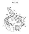
- FIGS. 2B-3C disclose stand alone cage of the present invention with screws.
- FIGS. 4A-4U disclose various embodiments of stand alone cages comprising dissimilar materials.
- FIG. 4V discloses a plate of a stand alone cage.
- FIGS. 5A-5W disclose various embodiments and component of a stand alone cage having an anti-backout feature.
- FIGS. 6A-6I discloses various embodiments and components of a stand alone cage having fins.
- FIGS. 6J-6U disclose a method of implanting a stand alone cage of the present invention.
- FIGS. 6V-6X discloses various components of a stand alone cage having fins.
- FIG. 7A-7B disclose barbed bone anchors of the present invention.
- FIG. 8 discloses a fusion device wherein the posterior wall and the first and second side walls form an integral body.
- FIG. 9 discloses an exploded view of the intervertebral fusion device of FIG. 8 wherein the integral body and the anterior wall are connected by a pair of pins.
- FIG. 10 discloses pins received within the interlocking features of the anterior wall.
- FIG. 11 discloses an embodiment of the present invention wherein the integral body comprises allogenic bone.
- FIGS. 12A-C disclose an inserter tip of the present invention.
- FIGS. 13A-D disclose front views of an embodiment of the present invention including a retaining plate, and components thereof
- FIGS. 14A-15B disclose top views of a retaining plate embodiment of the present invention including a living spring, and components thereof
- FIG. 16 discloses a front view of a retaining plate embodiment of the present invention including a living spring and a chamfered insertion feature.
- FIG. 17 discloses an inserter instrument engaged with a retaining plate of the present invention.
- FIG. 18 discloses a chamfered retaining plate and cage (partial) of the present invention.
- FIGS. 19A-C , 20 and 21 disclose different views of a fixation cage with a secondary washer for insertion into a disc space.
- FIG. 22 depicts a washer configured to be seated in a recess in an anterior portion of a fixation cage.
- a “cage” is the spacer of the present invention without the anterior wall. That is, the cage consists essentially of the posterior wall and the first and second side walls.
- the anterior wall may also be referred to as a “faceplate”.
- a first screw 3 having a distal tip 2 an intermediate shaft 4 having a threadform 6 thereon, and a proximal head 8 .
- the angled shaft portion 1 of the first screw 3 is made of a flexible material.
- a second screw 5 having a distal tip 2 an intermediate shaft 4 having a threadform 6 thereon, and a proximal head 8 .
- the angled shaft portion 7 includes a joint, such as a universal joint or a ball-and-socket joint.
- an intervertebral device comprising:
- the angled shaft is made of a flexible structure, while in others, the angled shaft includes a joint, such as a universal joint or a ball-and-socket joint.
- the screw can be replaced by a nail having barbs.
- the spacer comprises a cage consisting essentially of the posterior wall and the first and second side walls, and the anterior wall is a separately manufactured faceplate that is mated to the cage.
- the first throughhole extends upwards through the upper surface of the anterior wall, and the second throughhole extends downwards through the lower surface of the anterior wall.
- the first throughhole 22 has an anterior portion 26 that extends substantially perpendicular to the anterior wall, and a posterior portion 28 that extends to the upper surface 18 of the anterior wall.
- posterior portion 28 can extend partially or fully into the graft window (not just the upper surface).
- the anterior wall comprises a posterior surface 30
- the first throughhole extends upwards through the posterior surface of the anterior wall
- the second throughhole extends downwards through the posterior surface of the anterior wall
- a second screw received in the second throughhole, the second screw having a distal tip, an intermediate shaft having a threadform thereon, and a proximal head, wherein the shaft of the second screw is angled.
- the device of the present invention can generally be considered to be a medical implant comprising:
- the first hole preferably extends into the wall at an angle that is not perpendicular to the front surface, and the shaft of the first screw is angled.
- the shaft of the first screw is flexible.
- the present invention can also generally be considered to be a method of fixing a medical implant having a wall having a front surface and a first hole extending into the wall from the front surface, the method comprising the steps of:
- the flexible structure comprising the angled shaft can be either made of an intrinsically flexible material or an intrinsically stiff material having a geometry that enables flexing or bending.
- the surgeon advances the drive mechanism 973 of the inserter 371 perpendicular to the anterior wall of the spacer (and parallel to the endplates) to force the angled fixation device to take an angled trajectory into the adjacent vertebral body.
- a zero-profile or low-profile implant that can be used in a fusion procedure and sit completely inside the disc space.
- the implant includes features incorporated into one or more surfaces of the implant that control the amount of endplate subsidence into the implant. These features can be positioned around the periphery of the implant to capture targeted bone.
- a “controlled subsidence feature” on an implant provides increasing resistance against endplate subsidence as the subsidence progresses into the implant.
- the increase in resistance is generally accomplished by increasing the contact area between the implant and the endplates, thereby lowering the maximum stress experienced by the endplates.
- any surface having an acutely angled projection will function so as to control subsidence.
- Such a projection will have greater and greater contact with the endplate as the endplate subsides into the implant.
- controlled subsidence features include pyramids, cones and wedges.
- the controlled subsidence feature is a pointed projection extending outward from an upper or lower surface of the implant. Such a feature will also help prevent cage migration as well as increase the implant's rotational stability.
- the implant comprises two separate components: a three-walled cage plus an anterior faceplate having a desirable mechanical rigidity that can house a cam, bushing, and/or a thread form to allow anchors to pass therethrough, if desired.
- a method of securing the cage of the present invention to one or more levels of the spine with optional fixation devices such as bone anchors such as screws.
- the optional fixation device preferably passes through at least a portion of the anterior wall of the cage.
- the fixation devices enter the superior and inferior vertebral bodies somewhere in and along the anterior wall from within or partially within the disc space.
- the hybrid plate/cage assembly of the present invention having optional fixation essentially creates a near zero-profile assembly.
- the anterior wall is a separately-manufactured faceplate having anti-migration features.
- This faceplate can attach to a separate cage component made from such diverse materials as ceramics, hydroxyapatite, tricalcium phosphate, allograft, CFRP, PEEK and Endolign. These components can couple to each other from numerous planes (i.e., from the front-to-back, from the top-to-bottom, and from the side-to-side) so as to form a desirable net shape assembly that conforms to the patient anatomy based on the chosen surgical approach.
- a multi-piece intervertebral fusion device assembly having anti-migration/anti-expulsion features on both cage and faceplate components.
- an implant having a thin anterior wall containing features designed to control subsidence into bone.
- these features are present on both the upper and lower faces of the anterior wall and are distributed evenly across the anterior wall. More preferably they are symmetrically distributed.
- the anti-migration features of the faceplate are in the form of a pyramid, tooth, spike, diamond, keel or ridge. They are distributed anatomically across the front face to assist in load sharing with the graft spacer and to aid in ensuring final placement prior to fusion.
- an intervertebral device 201 for insertion into a disc space defined by opposing vertebral endplates, comprising
- each of the upper or lower surfaces of the anterior wall comprises a controlled subsidence feature.
- the controlled subsidence feature acts to increase contact area between the spacer and the endplates as subsidence increases.
- the controlled subsidence feature comprises an acutely angled projection 229 extending outwards from the upper or lower surface of the anterior wall.
- the controlled subsidence feature is selected from the group consisting of a pyramid, a cone and a wedge.
- the anterior wall comprises attachment features for attaching to the side walls.
- At least one side wall comprises a controlled subsidence feature.
- an intervertebral device for insertion into a disc space defined by opposing vertebral endplates, the device having an anterior-most surface and comprising
- At least one of the upper and lower surfaces of the faceplate comprises a controlled subsidence feature.
- an intervertebral device for insertion into a disc space defined by opposing vertebral endplates, comprising
- At least one of the upper and lower surfaces of the faceplate comprises a controlled subsidence feature.
- the anterior wall is characterized by a material having an intrinsic strength
- the remainder of the spacer is characterized by a material having an intrinsic strength
- the intrinsic strength of the material of the anterior wall is greater than the intrinsic strength of the material of the remainder of the spacer.
- the screw associated with the stand alone intervertebral fusion devices of the present invention has an enhanced fixation feature.
- a screw having an enhanced fixation feature is selected from the group consisting of:
- an intervertebral device for insertion into a disc space defined by opposing vertebral endplates, comprising
- an intervertebral implant comprising a spacer made of two or more components made of dissimilar materials coupled together to take advantage of the material properties of each selected material. These components can be coupled via various disclosed geometries.
- a device comprising a) a cage 411 comprising bone (preferably at least 50 v/o bone) and b) a faceplate 413 comprising a metallic or polymeric material, wherein the faceplate attaches to the bone.
- an anterior wall consisting essentially of a metallic material, with the remainder of the spacer consisting essentially of bone.
- an intervertebral device for insertion into a disc space defined by opposing vertebral endplates, comprising
- anterior wall is made of a first material and a remainder of the spacer is made of a second material
- anterior wall is fixed into the remainder of the spacer so that it does not float.
- the bone cage and metallic faceplate possess matching engagement features, such as dovetail features 415 .
- the metal faceplate has arms 417 that wrap around the bone cage and meet to form a posterior wall 419 .
- the metal faceplate 420 has lateral prongs 421 fit into mating recesses 423 machined into the anterior face 425 of the bone cage.
- the material of the anterior wall is less stiff than the material of the remainder of the spacer (i.e., the cage). This condition allows more load to be taken by bone graft contained within a hollow of the cage. This design could also provide a predetermined amount of micromotion and/or springback, which may be desirable.
- an intervertebral device for insertion into a disc space defined by opposing vertebral endplates, comprising
- the faceplate is front loaded onto the cage.
- the fixed connection of the present invention is accomplished by providing aligned holes in the cage and faceplate and inserting at least one cross pin 401 therethrough.
- the faceplate 422 has wings 424 extending posterior, and the wings have holes 425 .
- the holes of the faceplate aligned with holes 427 provided on the sidewalls 429 of the cage.
- the faceplate 430 has a pair of prongs 431 fitting into a central recess 433 machined into the anterior face 435 of the cage.
- the faceplate 437 and the anterior face 439 of the cage are mated through threaded features 441 .
- the faceplate 443 has a U-shape and is wraps around the anterior wall 445 of the cage. This faceplate is preferably press fit onto the anterior wall of the cage. The arms 442 of the faceplate contact the inferior 444 and superior 446 faces of the cage.
- the U-shaped faceplate has prongs 447 thereon that provide additional securement to the bone cage.
- the U-shaped faceplate has disperse lances 449 therein that provide additional securement to the bone cage.
- the U-shaped faceplate 451 is received into a recess in the anterior wall 453 of the cage so that the posterior face 455 of the faceplate is flush with the anterior surface 457 of the cage.
- the faceplate 463 has a U-shape and is wraps around the anterior wall 465 of the cage. This faceplate is preferably press fit onto the anterior wall of the cage. The arms 462 of the faceplate contact the side walls 464 of the cage.
- the faceplate 467 has a pin 469 extending posteriorly therefrom, and this pin extending into a mating recess 471 provided on the anterior face 473 of the cage.
- the faceplate is side loaded onto the cage.
- the faceplate 475 has dovetails 477 extending posteriorly therefrom, while the anterior face 479 of the bone cage 481 has dovetail recesses 483 formed therein.
- the dovetails of the faceplate are sideloaded into the dovetail recesses.
- the faceplate 485 has tabs 487 extending posteriorly therefrom, within holes 489 extending tabs.
- This faceplate is sideloaded into a cage having a recess 491 that extends substantially laterally across the anterior face 493 of the cage and partially down a sidewall 495 as well.
- the upper surface 496 of the cage has a pair of holes 497 bored therein so that the holes of the cage align with the holes of the faceplate. Into these aligned holes is inserted an insertion pin 498 .
- the faceplate is top loaded onto the cage.
- the faceplate 301 has tabs 303 extending laterally therefrom, and insertion pins 305 extending from the tabs in the superior direction.
- the cage 307 has tabs 309 extending laterally therefrom, and insertion holes extending through the tabs in the superior direction. The cage and faceplate are mated in a press fit fashion so that the insertion pin of the faceplate extends through the insertion hole of the cage.
- the faceplate 311 has tabs 313 extending laterally therefrom.
- the cage 317 has tabs 319 extending laterally therefrom. These tabs are formed in a jigsaw puzzle manner so that the cage and faceplate can be mated in a press fit fashion so that the tab of the faceplate mates with the tab of the cage.
- the faceplate 321 has a dovetail 323 extending posteriorly therefrom.
- the anterior wall 325 of the cage 327 has a dovetail recess therein extending from the upper surface 329 to the lower surface of the cage.
- the faceplate is top or bottom loaded into the cage so that the dovetail and corresponding recess mate.
- the faceplate 331 is essentially a band that wraps around the cage.
- a plurality of crush ribs 333 that enhance the friction fit with the cage (not shown).
- the faceplate 341 has outer arms 335 that form an outside dovetail with the cage 343 .
- the faceplate 351 has a-plurality of dovetails 353 extending posteriorly therefrom.
- the anterior wall 355 of the cage 357 has a plurality of dovetail recesses therein extending from the upper surface 359 to the lower surface of the cage.
- the faceplate is top or bottom loaded into the cage so that the dovetails and corresponding recesses mate.
- the fixed connection of the present invention is accomplished by providing insertion pins 403 on the posterior wall 405 of the faceplate 407 , along with aligned recesses on the anterior portion of the cage.
- the insertion pins are then cooled so that they contract.
- the insertion pins are then inserted into the aligned recesses in the anterior portion of the cage. Once the insertion pins warm, they expand and provide a secure friction fit.
- assembly of the two components could take place in the operating room due to the modularity of the design, thus allowing for intra-operative decision making.
- bone graft may include both synthetic bone (such as synthetic hydroxyapatite) and natural bone (such as allograft).
- Screw backout is a well known safety issue. Accordingly, the surgeon must often engage in extra surgical steps, such as passing another instrument through to the site and turning a cam or cover plate.
- the screw hole 500 includes a machined-in ring 501 that is at least partially (and preferably fully) circumferential and is fully contained within the screw hole.
- the proximal end portion 503 of its thread 504 includes a proximal sidewall 535 that runs parallel to the ring.
- the thread passes over the ring to allow passage of the screw into the hole.
- the distal portion of the screw head proximally abuts the ring, thereby preventing further advance.
- the last turn of the screw thread i.e., the proximal end portion of the thread having the parallel sidewall
- the ring is sized to provide engagement with the root and/or side wells of the crest of the thread of the screw shank to allow for screw advancement. This mimics a helical threadform machined into the aperture, but need not be a helix.
- the interface between the screw and the spacer in these embodiments should have superior push out strength, ease of use and backout resistance (as compared to previous designs such as a bushing). This is because it is an integral machined-in lip with fewer failure modes.
- this design of the present invention will allow the surgeon to secure the screw in a single step-by simply advancing and bottoming out the screw in the spacer, thereby eliminating extra steps for the surgeon to perform.
- the design is robust in that it can accommodate rigid or variable screws and allow for controlled screw toggle depending on the surgeon's desire.
- an intervertebral device for insertion into a disc space defined by opposing vertebral endplates, comprising
- anterior wall has a first hole surface having a first ring extending therefrom
- first thread has a proximal end portion having a proximal side wall that runs substantially parallel to the ring.
- the proximal end portion of the thread can have a contour selected from the group consisting of a straight cut 503 (as in FIG. 5C ), a relief cut, or a reverse cut 505 (as in FIG. 5D ).
- the machined-in ring can have a contour selected from the group consisting of a straight cut 507 (as in FIG. 5F ), a relief cut 509 (as in FIG. 5G ) or a reverse cut 508 (as in FIG. 5H ).
- the proximal end portion of the thread having the parallel sidewall includes substantially all of the run-out portion of the thread.
- an intervertebral device for insertion into a disc space defined by opposing vertebral endplates, comprising
- anterior wall has a first hole surface 530 having a first ring 531 extending therefrom,
- first thread has a proximal end portion having a proximal side wall 535 that runs substantially parallel to the ring.
- the first ring abuts the proximal side wall to prevent backout.
- the ring is sized to allow for passage of the first thread to allow for screw advancement.
- the first ring is fully circumferential, while in others it is partially circumferential.
- the first ring is an integral portion of the anterior wall. In some embodiments, the first ring is manufactured separately from the anterior wall.
- the present invention generally relates to a medical implant comprising:
- the wall has a first hole surface having a first ring extending therefrom
- first thread has a proximal end portion having a proximal sidewall that runs substantially parallel to the ring.
- the method of using the present invention generally relates to a method of fixing an implant comprising a wall having a front surface and a first hole extending into the wall from the front surface, wherein the wall has a first hole surface having a first ring extending therefrom, the method comprising the steps of:
- the first screw is inserted into the bone so that the proximal end portion of the first thread is advanced past the ring. In some embodiments, the first screw is inserted into the bone so that the ring is disposed between the proximal end portion of the first thread and the proximal head. In some embodiments, the length of this neck portion can be varied depending on the level of desired compression.
- FIGS. 5L-5N there is a helical ring 551 to prevent the screw 553 from backing out after insertion.
- the pitch and shape of the helical ring matches that of the screw so that the screw can be easily inserted.
- the bottom of the screw head 555 will be in contact with the top 557 of the helical ring.
- all of the threads 559 on the screw will have fully passed through the helix on the faceplate and the helix will reside between the bottom of the screw head and the end of the last thread on the screw.
- the threads would have to be re-engaged with the helix. An axial load would not allow the screw to backout once the screw is properly inserted.
- this anti-backout embodiment comprises a) multiple spring tabs 561 that are formed from recesses 563 cut into the distal surface 565 of the head of the screw and b) a mating groove in the faceplate.
- the bottom of the screw head pushes against a continuous ring so that it cannot go through the face plate.
- protrusions 567 on the screw head spring tabs pop into the mating groove on the faceplate to prevent the screw from being able to back out of the faceplate.
- FIGS. 5T-5W in this embodiment anti-backout is achieved through the use of a balseal 569 .
- a groove 571 is cut into the faceplate in which a circular spring 573 is placed.
- Another groove 575 is cut into the head 577 of the screw 579 .
- the bottom of the head will become fully seated against a ring in the faceplate.
- the geometry of the head of the screw will have flattened out the spring and once fully seated the spring will recover to its normal position and be housed in the groove on the head of the screw thereby preventing the screw from backing out.
- the geometry on the head of the screw can be designed so that a minimal amount of force (such as one pound) is required to lock the screw into the spring but a greater force (such as 25 pounds) is required to removed the screw from the balseal.
- some spine surgeons prefer not to insert a plate on the anterior surface of a patient with fixation through the anterior face of the cephalaud and caudal vertebral bodies. Often times, the plate can be considered to be too proud and its profile can sometimes cause patient discomfort and cause dysphasia.
- a method of securing an intervertebral fusion cage to an intervertebral disc space with fixation elements and numerous implant embodiments therefor.
- the fixation elements such as fins, pins, blades, plates, keels, and hooks
- the fixation elements are inserted up against a proximal face of the cage.
- the fixation elements are inserted into the cage in an orientation substantially perpendicular to the proximal face of the cage, and substantially in-line with the inserter.
- the fixation elements are then deflected outward from the cage during insertion by a sloped feature on the anterior surface of the cage.
- this sloped feature is a tapered section defining an upward sloping surface and a downward sloping surface.
- the deflected fixation elements penetrate the adjacent vertebral bodies and are secured in place with a compression cap.
- fixation elements may further provide compression onto the cage.
- the fixation elements are preferably made of materials and possess shapes designed to accomplish this function. Materials that preferably allow the fixation elements to accomplish this compression function include metals such as stainless steel and titanium alloy, polymers, autograft, allograft, ceramics, and resorbable materials such as HA and TCP. Geometries that preferably allow the fixation elements to accomplish this compression function include those provided in FIGS. 6A-6W .
- the fixation cage of the present invention allows the surgeon to create a smaller incision and access site for the cage and fixation elements because direct access that is parallel to the disc space is provided.
- the in-line insertion of the fixation elements also allows the surgeon to avoid having to insert the fixation elements on a high angle through sometimes challenging approaches.
- an intervertebral implant 600 comprising:
- distal section of the first fin extends above the upper surface of the anterior wall
- the anterior wall further comprises a threaded hole 635 located between the upward and downward sloping surfaces thereof, wherein the compression cap comprises a distal thread 637 , and wherein the threaded hole threadably receives the thread of the compression cap.
- a second fin 639 having a proximal section 641 , an intermediate section 643 and a distal section 645 , wherein the second fin contacts the downward sloping section of the tapered section of the anterior face, wherein the distal section of the second fin extends below the lower surface of the anterior wall, and wherein the proximal section of the second fin contacts the second portion of the compression cap.
- the second fin provides for bilateral fixation of the cage between the opposing vertebral bodies.
- the spacer further comprises a hollow portion 647 between the anterior and posterior walls, wherein bone graft is contained within the hollow, and wherein the fins impart compression onto the bone graft.
- the fins provide an additional benefit of bone graft compression to the device.
- the first fin comprises a concave surface 649 and an opposing convex surface 651 . These surfaces provide the fin with an upward or downward curve that allows the fin to enter the opposing vertebral bodies in an orientation more perpendicular to the endplates.
- the convex surface of the first fin contacts the upward sloping surface of the tapered portion of the anterior surface of the anterior wall. This allows the upward sloping surface to determine the angle of the fin as it extends into the vertebral body.
- At least one of the concave and convex surfaces of the first fin has a tooth 653 extending therefrom.
- These teeth provide additional fixation character to the fin.
- at least one of the concave and convex surfaces of the first fin has a plurality of teeth extending therefrom.
- At least one of the concave and convex surfaces of the first fin has a groove 655 therein.
- This groove provides additional fixation character to the fin, or may be designed to allow for intentional bending/flexing to occur.
- the first fin further comprises at least one side surface 657 extending between the concave and convex surfaces, wherein the at least one side surface comprises a tooth 659 thereon. These teeth provide additional fixation character to the fin.
- the distal section of the first fin comprises at least two tynes 660 forming a fork.
- the fork provides two points of fixation and may provide a benefit when existing hardware from a previous surgery is in the space.
- the proximal portion of the first fin has wings 661 extending laterally therefrom.
- the wings provide a stop and a pivot point.
- the wings are flexible so as to provide rentention into the tapered anterior wall surfaces.
- the distal portion of the first fin is tapered 664 .
- the taper provides ease of insertion into the bone segment.
- the embodiment of FIG. 6H can have a plurality of throughholes running transverse to the fin, as shown in FIG. 6X .
- the proximal portion of the first fin has a longitudinal groove 666 therein to provide flexibility and/or retention.
- the proximal section of the first fin contacts the upward sloping section of the tapered section of the anterior face. In some embodiments, the intermediate section of the first fin contacts the upward sloping section of the tapered section of the anterior face.
- the first fin extends above the upper surface of the anterior wall at an angle defined by the upward sloping section of the anterior wall. This allows the angle at which the fin extends into the vertebral body to be predetermined by the implant.
- At least of the anterior wall, posterior wall, and first and second side walls of the intervertebral spacer further comprise an upper surface 663 and a lower surface 665 that are toothed 667 . These teeth provide additional fixation of the cage to the vertebral bodies.
- each of the anterior wall, posterior wall, and first and second side walls of the intervertebral spacer further comprise upper and lower surfaces that are toothed.
- FIGS. 6V and 6W disclose are alternate embodiments of a compression cap for the blade version. Both would have a fastener (i.e, a screw) that would pass through it and would attach to the opening on the anterior face of the cage.
- FIG. 6V discloses cap 668 and FIG. 6W discloses cap 670 .
- the insertion of the cage of the present invention may follow the following procedure.
- FIG. 6J there is provided the spacer 601 of the present invention adjacent insertion device 670 .
- FIG. 6K the spacer is attached to the insertion device to form assembly 671 .
- FIGS. 6L and 6M the assembly is inserted into intervertebral disc space DS.
- FIGS. 6N and 60 first fin 621 is inserted into a groove 673 of the insertion device.
- FIG. 6P-6R the fin is pressed into place with inserter rod 675 .
- compression cap 677 is inserted into the assembly to lock the fin to the spacer.
- the cages of the present invention are preferably suited for use in the cervical spine, they may also be used in the lumbar and thoracic spine as well.
- the cages of the present invention are preferably suited for use with a pair of bone screw, they may also be used with more than two fasteners. In some cases, the cage of the present invention is fastened with three bone screws provided in either a “one up/two down” or “two up/one down” arrangement.
- the screw 701 used with fusion cages of the present invention is modified wherein the thread of the screw is replaced with substantially circumferential ribs 703 or barbs.
- the device uses fins, barbs, or ribs as opposed to a threaded means for its fixation strength. This device can be tapped into a predrilled hole instead of threaded. This can lead to a faster and easier insertion of the fixation device without the risk of stripping out a threaded hole and losing fixation strength.
- the number of barbs and the geometry of the barbs can be designed to get the best fixation strength possible while requiring less force for insertion.
- the spacer comprises bone extending continuously between the anterior and posterior walls, and wherein the fins impart compression to the bone.
- an intervertebral fusion device of the present invention comprising:
- posterior wall and the first and second side walls form an integral body 759 .
- FIG. 9 discloses an exploded view of the spacer of FIG. 8 wherein the integral body 759 and the anterior wall 753 are connected by a pair of pins 761 .
- the anterior wall 753 has tongue features 754 having holes therein, while the anterior portion 756 of the integral body has groove features 758 having holes 760 therein, wherein the holes align when the tongue and groove interlock and receive the pins.
- these components may be assembled with a one-way snap feature.
- FIG. 10 discloses how pins 761 are received within the tongue features of the anterior wall 753 .
- FIG. 11 discloses an embodiment of the present invention wherein the spacer comprises an anterior wall 753 connected to an integral body 759 , wherein the integral body is substantially solid and comprises the two side walls and a posterior wall, and is made of allogenic bone.
- FIGS. 12A-C disclose an inserter tip 760 of the present invention.
- the inserter tip comprises a proximal barrel 761 forming two distal tynes 763 .
- Each tyne has an attachment feature 765 for grabbing the implant and an annulus 767 for receiving a bone screw.
- the present invention comprises a retaining element that retains these anchoring screws within the cage. It preferably includes an additional component, namely a retaining plate 801 , which is shown by itself in FIG. 13A .
- the retaining plate is slidably mounted on the anterior face 803 of the cage, which is shown by itself in FIG. 13B .
- the assembly of the retaining plate upon the anterior face of the cage is shown in FIGS. 13C and 13D .
- This plate can be slidably mounted to the cage using conventional mounting mechanisms such as a dovetail or track.
- the retaining plate comprises several through-holes 804 —one for each screw hole 805 provided in the cage. The cage could be inserted with the plate holes misaligned with the holes of the cage.
- the plate is in its “retain” or “closed” position.
- the plate is translated into an “open” position whereby the holes in the plate are aligned with the holes in the cage, as in FIG. 13C .
- This is the position for screw insertion.
- the anchor screws are then inserted through the aligned holes in the retaining plate and cage so that they anchor the cage into the vertebrae.
- the plate is translated into its “retain” position (of FIG. 13D ) so that the through-holes of the plate are again misaligned with the screw holes of the cage. The misalignment of the screw holes prevents the screws from backing out of the cage.
- an intervertebral device for insertion into a disc space defined by opposing vertebral endplates, comprising:
- the first hole of the plate aligns with the first hole of the spacer to allow passage of the screw therethrough
- mechanisms can be provided that prevent the plate from post-operatively moving back to its initial open position. Some such mechanisms direct engagement of components in the medial-lateral direction (as in FIGS. 13C and 13D ), while other direct engagement of components in the anterior-posterior direction.
- a protrusion-type locking feature 811 on the anterior surface of the cage engages a mating recess 813 on a locking arm 815 on the plate, thereby preventing the plate from returning to the “open” position.
- This locking mechanism could be provided via a number of different embodiments, including features that move in a medial-lateral or anterior-posterior direction to produce the desired locking.
- a protruding mating feature 811 provided on the anterior face of the cage moves laterally to engage a recessed mating feature 813 provided on the plate when the device is in its “retain” position, thereby preventing the plate from returning to the “open” position.
- one of these features is provided as a flexible or spring-like element so that the mating features snap into place, thereby locking the relative positions of the plate and cage.
- These mating features can also be designed to index the plate between “open” and “retain” positions.
- the protrusion can be provided at the end of a flexible arm that moves laterally across the plate to engage the recess.
- a recessed mating feature provided on the anterior face of the cage could engage a protruding mating feature provided on the plate when the device is in its “retain” position, again locking the relative positions of the plate.
- a moveable protrusion (such as a ball detent) is mounted in the cage to move in the A/P direction and engage a recess in the plate, again indexing the plate in the two positions.
- a locking arm cut into the locking plate with a deflection direction in the A/P direction could engage with a recess cut into the cage.
- the plate-cage assembly is first loaded into the disc space.
- the insertion instrument used for cage insertion and screw placement has an additional mechanism that laterally slides the plate over the anterior surface of the cage. When the plate is slid into “open” position, screws are inserted therethrough. When the plate is then slid into “retain” position, the holes in the plate and cage mis-align, thereby preventing the screws from backing out.
- the plate is slidable in a medial-lateral direction across the anterior face of the spacer, while in others the plate is slidable in an upper-lower direction across the anterior face of the spacer.
- the spacer and plate include a locking feature to retain the holes in a mis-aligned state.
- the locking feature comprises a locking arm or a ball detent.
- the locking feature locks in a medial-lateral direction, while in others the locking feature locks in an anterior-posterior direction, and in still others the locking feature locks in an upper-lower direction.
- the locking feature comprises a protrusion and a recess.
- a sidewall 821 of the retaining plate 823 is equipped with a living spring 825 .
- This plate is adapted to slidably engage a pair of parallel rails (not shown) extending laterally across the anterior face of the cage. The lateral movement of the plate is arrested by stop 826 .
- the placement of through-holes 827 on the plate is predetermined so that a) the plate through-holes align with the screw holes 829 of the cage when the plate is biased so as to fully compress the spring (as in FIG. 14B ), and b) the plate through-holes mis-align with the screw holes of the cage when the bias is released so as to allow expansion of the spring (as in FIG. 15B ).
- FIG. 16 presents another embodiment of a plate 830 having a sidewall 831 equipped with a “living spring” 833 .
- the opposing sidewall 835 of the plate has a chamfer feature 837 that mates with a chamfered surface on a grabber instrument.
- the device is typically installed with the plate in its unbiased position.
- opposed jaws 841 of a grabber instrument Prior to inserting screws into the cage, opposed jaws 841 of a grabber instrument are placed about the device to contact the chamfered surface 837 of the plate and a sidewall 834 of the cage. The grabber instrument is then actuated so that its jaws 841 are compressed so as to compress the spring 833 .
- the living spring is replaced with a stand-alone compression spring or leaf spring.
- the plate may be altered so as to eliminate the need for the grabber instrument discussed above.
- the through-holes 851 of the plate are provided with unilateral chamfers 853 that mate with the distal tip 855 of the screw being inserted.
- spring 861 compress and plate 857 to slide laterally, and thereby align the holes of the plate with the holes 859 of the cage.
- the living spring component 861 of the plate expands so as to cause mis-alignment of the holes, thereby preventing screw back-out.
- the plate further comprises first and second sidewalls, wherein the first sidewall comprises a living spring.
- the second sidewall of the plate comprises a feature (preferably, a chamfer) for mating with a grabber instrument.
- the holes of the plate comprise chamfers adapted to mate with the distal tip of the screw.
- Prior art references related to a fixation cage with a secondary washer include: U.S. Patent Publication 2010-0057206; U.S. Patent Publication 2009-0088849; U.S. Patent Publication 2010-0145459; U.S. Pat. Nos. 6,730,127; 7,662,182; 6,972,019; U.S. Patent Publication 2008-0249569; U.S. Patent Publication 2009-0105831; U.S. Pat. Nos. 7,306,605; 7,288,094; U.S. Patent Publication 2010-0312345; U.S. Patent Publication 2010-0286777; U.S. Pat. No. 6,945,973; U.S. Patent Publication 2010-0106249; U.S. Pat.
- Conventional fixation cages have several means for capturing angled bone-engaging screws and ensuring that those screws do not back out.
- Conventional anti-backout mechanisms include assembled rotating cover plates, cams, bushings, expanding screws, and set screws.
- One particular anti-backout means is a secondary cover plate that either snaps onto the cage itself or is docked to the cage and secured to the cage faceplate using additional hardware, such as a screw. This secondary cover plate can fully or partially cover the most proximal portion of the screw head and could in theory prevent any screw backout.
- FIGS. 5C-E describe some embodiments utilizing a particular anti-backout mechanism in which the proximal end portion of the screwthread has a parallel sidewall.
- the ring is replaced by a stand-alone washer positioned anterior to the screw hole.
- the device may further comprise a secondary washer.
- the purpose of the secondary washer is to further resist screw backout.
- the secondary washer may preferably be loosely attached to the proximal shaft of a final fixation screw.
- the screw-washer combination is the last item added to the cage construct to complete the device assembly.
- the washer is designed to float in a predetermined zone of the fixation screw distal of the screw head, and ideally would be removed only with special equipment.
- an intervertebral device for insertion into a disc space defined by opposing vertebral endplates, comprising:
- the washer is designed to seat on the anterior (proximal) face of the anterior wall of the cage, against the region of the wall surrounding the corresponding screw-hole. It may be held in place by a snap clip feature 951 and corresponding recess 953 residing on the upper or lower face of the cage (shown in FIGS. 20 and 21 ).
- the washer further comprises design features that abut corresponding features in the cage to ensure proper positioning upon final seating.
- the periphery of the washer has a contour 961 that matches and seats in a recess in the anterior portion of the cage.
- the design features may resist washer rotation.
- the distal face of the washer has at least one projection 963 that matches and seats in a corresponding recess in the anterior face of the cage.
- the proximal or distal face of the washer has at least one projection 965 that serves to interrupt screw backout.
- the washer comprises screw engagement features. Upon the fixation screw's final rotation, the screw will pass through the aperture in the washer at an angled trajectory. Features of the washer surrounding the aperture could engage features of the screw in its final degrees of rotation so as to prevent easy counter-clockwise removal of the screw.
- the head comprises at least one flange (i.e., the washer) extending therefrom, the flange having a proximal face and a distal face.
Landscapes
- Health & Medical Sciences (AREA)
- Orthopedic Medicine & Surgery (AREA)
- Engineering & Computer Science (AREA)
- Biomedical Technology (AREA)
- Neurology (AREA)
- Life Sciences & Earth Sciences (AREA)
- Public Health (AREA)
- Heart & Thoracic Surgery (AREA)
- Veterinary Medicine (AREA)
- Animal Behavior & Ethology (AREA)
- General Health & Medical Sciences (AREA)
- Surgery (AREA)
- Transplantation (AREA)
- Cardiology (AREA)
- Oral & Maxillofacial Surgery (AREA)
- Vascular Medicine (AREA)
- Molecular Biology (AREA)
- Medical Informatics (AREA)
- Nuclear Medicine, Radiotherapy & Molecular Imaging (AREA)
- Physical Education & Sports Medicine (AREA)
- Prostheses (AREA)
- Surgical Instruments (AREA)
Abstract
An angled fixation device, such as an angled screw. This angled fixation device may be used by the surgeon to secure a spacer to a spinal disc space. The proximal end portion of the angled fixation device is driven perpendicular to the anterior wall of the spacer, and so is parallel to the vertebral endplates and in-line with the inserter. The distal end portion of the angled fixation device is oriented at about a 45 degree angle (plus or minus 30 degrees) to the vertebral endplate it enters.
Description
This is a divisional patent application of U.S. Ser. No. 13/237,233, filed Sep. 20, 2011, which claims priority from U.S. Ser. No. 61/385,959, filed Sep. 23, 2010, the specification of each of which is incorporated by reference in its entirety.
U.S. Ser. No. 13/237,233, filed Sep. 20, 2011, further claims priority from U.S. Ser. No. 61/466,309, filed Mar. 22, 2011, and entitled “Novel Implant Inserter Having a Laterally-Extending Dovetail Engagement Feature,” the specification of which is incorporated by reference in its entirety. Ser. No. 13/237,233, filed Sep. 20, 2011, is related to U.S. Ser. No. 13/237,200 filed Sep. 20, 2011, entitled “Novel Implant Inserter Having a Laterally-Extending Dovetail Engagement Feature,” the specification of which is incorporated by reference in its entirety.
U.S. Ser. No. 13/237,233, filed Sep. 20, 2011, further claims priority from U.S. Ser. No. 61/466,321, filed Mar. 22, 2011, and entitled “Fusion Cage with In-Line Single Piece Fixation,” the specification of which is incorporated by reference in its entirety. U.S. Ser. No. 13/237,233, filed Sep. 20, 2011, is related to U.S. Ser. No. 13/237,174, filed Sep. 20, 2011, entitled “Fusion Cage with In-Line Single Piece Fixation,” the specification of which is incorporated by reference in its entirety.
During cervical spinal surgery for the fusion of an intervertebral disc, an anterior approach, discectomy and insertion of a spacer/cage are often performed. However, in these situations, the spine surgeon often prefers not to insert a plate on the anterior surface of the disc space with fixation through the anterior face of the cephalaud and caudal vertebral bodies. This reluctance stems from the observation that the anterior plate can be situated too proud and so its profile can sometimes cause patient discomfort and cause dysphasia and/or dysphonia.
In some fusion cases using a stand alone spacer, the surgeon must insert a fixation device (such as a screw) into the spacer at a sharp angle through sometimes challenging approaches. This can be especially difficult for the cervical spine, as the surgeon needs to either deliver the screw down into the inferior vertebral body but may be obstructed by the patient's chin, or deliver the screw up into the superior vertebral body but may be obstructed by the patient's sternum.
U.S. Pat. No. 7,135,043 (Nakahara) discloses an intervertebral cage comprising regulated insertion direction ridges. The cage may include a main body defined by an upper surface, a lower surface, and a pair of side surfaces. A withdrawal prevention portion is provided on the upper and/or the lower surfaces of the main body and asymmetrically with respect to the side surfaces in a top or bottom plan view. The withdrawal prevention portion regulates an insertion direction of the intervertebral cage. The portion of the Nakahara device that holds the screws does not possess teeth upon its upper and lower surfaces.
U.S. Patent Publication No. 2007-0250167 (“Bray”) discloses a device for the fixation and support of bone bodies includes a base member for implantation into a patient at a location between two bone bodies. The base member of the device includes an enclosed chamber for receiving fusion material and apertures for receiving bone fasteners that can be embedded into the adjacent bone bodies. The device further includes protrusions extending from the base member, wherein the protrusions are configured for engagement with one or more bone bodies upon implantation and for progressive penetration into at least one bone body over a period of time subsequent to the implantation. However, the faceplate that holds the screws is not designed to be implanted in the disc space, but rather cloaks the anterior wall of the upper vertebral body.
The Globus Coalition Cage has protrusions that begin from the anterior face, and upon insertion, displace bone from the anterior face through the desired depth in a track formation rather than penetrating from within the space.
U.S. Pat. No. 7,232,464 (Mathieu) discloses an intervertebral implant in the form of a three-dimensional structure comprising (a) a top side and an underside that are designed to rest against the end plates of two adjacent vertebras, (b) a left side face and a right side face, (c) a front face and a rear face, (d) a horizontal center plane situated between the top side and the underside, (e) a vertical center plane situated between the left side face and the right side face and (f) a plurality of boreholes passing through the implant structure that are designed to receive longitudinal affixation elements, the axes of said elements intersecting the horizontal center plane. At least one of the boreholes is designed in a manner that the affixation element received in it can be rigidly connected to the intervertebral implant. The connection is implemented using a thread or by matching conical surfaces.
U.S. Patent Publication No. 2008-0306596 (“Jones”) discloses a method and apparatus for use in spinal fusion procedures. An interbody fusion device has a first piece that is a load bearing device designed to bear the axial loading from the end plates of adjacent vertebrae. A second piece of the interbody fusion device is a retention device whose function is to prevent migration of the load bearing device. One or more fasteners secure the retention device to the vertebrae above and below the load bearing device. The fasteners cause the end plates of the vertebrae to compress the end plates to the load bearing device to facilitate proper fusion.
U.S. Patent Publication No. 2008-0249625 (Waugh) discloses a composite interbody spacer includes a first portion (such as a faceplate) formed of a first material and a second portion (such as a cage) formed of a second material.
U.S. Patent Publication No. 2008-0249575 (“Waugh”) discloses a stand alone fusion cage in which the apertures that receive the bone anchors have an integral locking ring formed therein.
PCT Published Patent Application WO 02/13732 (“Bramlet”) discloses an apparatus and method for fusing opposing spinal vertebrae. In an embodiment for a spinal implant of the present invention, the implant includes a body assembly and a retention member coupled to the body assembly. The retention member includes a tang where the tang is extendible from the body assembly. In a method of the present invention, the method includes the step of inserting an implant between adjacent vertebrae with a retention member of the implant in a first retracted configuration. The method also includes the step of configuring the retention member in a second extended configuration wherein the retention member is in its second extended configuration, a portion of a tang of the retention member extends from the implant and into one of the adjacent vertebrae.
U.S. Pat. No. 6,336,928 (“DePuy France”) discloses a device for joining at least two vertebral bodies, which comprises at least one plate equipped at each end with anchoring parts which can be introduced substantially vertically into seats previously established in the vertebral bodies to be joined, and then, after introduction, can be folded back at an angle towards one another in order to exert a constant compression of the vertebral bodies and to ensure perfect anchoring, wherein each anchoring part is connected to the ends of the corresponding plate via a central connection zone delimiting two profiled notches in order to permit deformation of the zone, in such a way that each pair of anchoring parts permits a compression, both at the level of the plate and at the level of its ends, and in such a way that the anchoring parts at each end of the plate permit a clamping which prevents any extraction.
U.S. Pat. No. 6,773,437 (“Ogilvie”) discloses a fusionless method of correcting spinal deformities in growing adolescents is disclosed utilizing a shape memory alloy staple. Various embodiments of the shape memory alloy staple include features such as barbs on the inner and outer surfaces of the prongs in the shape memory alloy staple as well as the use of notches on the crossbar or cross plate connecting the prongs to the shape memory alloy staple. In some embodiments, the shape memory alloy staple has an aperture defined through the cross plate for receiving a bone screw or other bone anchor which in turn allows the interconnection of a longitudinal member.
U.S. Pat. No. 7,594,931 (“LDR I”) discloses an intervertebral arthrodesis for insertion in an intervertebral space separating opposite faces of two adjacent vertebrae has a ring shaped intervertebral cage having a bar that extends perpendicular to the axis of the spine. The bar has a height less than the rest of the cage. A surface of the cage contacting the vertebrae has an undulating shape for limiting sliding of the cage in a plane parallel to the vertebrae faces.
PCT Published Patent Application WO 2008/149223 (“LDR II”) discloses an intersomatic cage, an intervertebral prosthesis, an anchoring device and an instrument for implantation of the cage or the prosthesis and the anchoring device, as well as a system and a method for implanting spinal implants and anchoring devices in vertebrae. An intersomatic cage or an intervertebral prosthesis fit closely to the anchoring device, which includes a body of elongated shape on a longitudinal axis, of curved shape describing, along the longitudinal axis, an arc whose dimensions and radius of curvature are designed in such a manner that the anchoring device may be implanted in the vertebral plate of a vertebra by presenting its longitudinal axis substantially along the plane of the intervertebral space, where the anchoring device is inserted, by means of the instrument, through a slot located in at least one peripheral wall of the cage or on at least one plate of the intervertebral disc prosthesis to penetrate into at least one vertebral plate
PCT Published Patent Application WO-2010/028045 (“Lawton”) discloses an intervertebral implant for insertion into an intervertebral disc space between adjacent vertebral bodies or between two bone portions. The implant includes a spacer portion, a plate portion operatively coupled to the spacer portion and one or more blades for securing the implant to the adjacent vertebral bodies. The blades preferably include superior and inferior cylindrical pins for engaging the adjacent vertebral bodies. The implant may be configured to be inserted via a direct lateral transposals approach. Alternatively, the implant may be configured for insertion via an anterior approach.
U.S. Published Patent Application 2005-0149192 (“Zucherman I”) discloses an intervertebral implant has a fusion body with at least one keel that anchors the implant into cancellous bone of at least one vertebral body. A method for implantation includes lateral implantation of the implant.
U.S. Published Patent Application 2005-0149193 (“Zucherman II”) discloses an intervertebral implant has a fusion body with at least one keel that anchors the implant into cancellous bone of at least one vertebral body. A method for implantation includes lateral implantation of the implant.
U.S. Published Patent Application 2004-0260286 (“Ferree”) discloses an intradiscal components associated with Total Disc Replacements (TDRs), for example, are maintained in a disc space with keels having attributes that resist extrusion, pull-out, and/or backout. In the preferred embodiment, the keel is curved to resist extrusion, particularly anterior or posterior extrusion. The invention may include a TDR with a pair of endplates, each with a keel extending into a different vertebral body, and wherein the keels are angled or curved in different directions to resist extrusion. In alternative embodiments, the keel may include one or more members that extend outwardly to resist extrusion. Such members may be spring-biased, composed of a shape-memory material, or extend outwardly in response to an applied mechanical force, as might be applied by turning a screw. The keel may further include a bone-ingrowth plug or coating or ‘teeth’ to resist extrusion. Keels according to the invention may also be configured to resist extrusion through the addition of an elongate member that penetrates a vertebral body and the keel. Such a member may be a secondary keel or screw.
U.S. Published Patent Application 2008-0167666 (“Fiere”) discloses equipment including at least one U-shaped clip whose lateral branches have sections and widths such that they may be inserted in the vertebral bodies of two vertebrae by impaction on the intermediate branch of the clip, so as to rest along the cortical bones of the vertebral bodies, and whose intermediate branch is deformable in such a way as to allow a reduction of the distance between the lateral branches; the intermediate branch, before implantation, has a length such that one of the lateral branches may be positioned slightly above the cortical bone forming the plate of the subjacent vertebra while the other lateral branch may be positioned slightly below the cortical bone forming the plate of the subjacent vertebra, and has, after deformation, a length such that the two lateral branches may be brought closer to each other.
U.S. Published Patent Application 2010-0004747 (“Lin”) discloses a trans-vertebral and intra-vertebral plate and a rectangular cage with a slot for the plate of spinal fixation device are for neutralizing intervertebral movement for the spinal interbody fusion. The rectangular cage with a vertical or oblique slot is inserted into the intervertebral space from the lateral or anterior side of the spinal column and then the plate is inserted through the slot of the cage and hammered into and buried inside two adjacent vertebral bodies, to achieve three-dimensional intervertebral fixation.
The cited art does not disclose a fusion device that accommodates anti-migration fixation elements adjacent to the device, wherein the anti-migration fixation elements are then secured to the fusion device with another component.
The prior art does not disclose a zero-profile cage with anti migration elements secured into bone approximately adjacent to a surface of the cage within disc space, wherein the anti-migration fixation elements have the ability to provide compression onto the graft area upon addition of another component to the construct.
WO2009-064644 (Synthes) discloses a low profile intervertebral implant for implantation in an intervertebral disc space in-between adjacent vertebral bodies. The intervertebral implant includes a plate preferably coupled to a spacer. The plate is preferably formed from a first material and the spacer is preferably formed from a second material, the first material being different from the second material. The plate is preferably sized and configured so that the plate does not extend beyond the perimeter of the spacer. In this manner, the plate preferably does not increase the height profile of the spacer and the plate may be implanted within the intervertebral disc space in conjunction with the spacer.
In a first embodiment of the present invention, there is provided an angled fixation device, such as an angled screw. This angled fixation device may be used by the surgeon to secure a spacer to a spinal disc space. The proximal end portion of the angled fixation device is driven perpendicular to the anterior wall of the spacer, and so is parallel to the vertebral endplates and in-line with the inserter. The distal end portion of the angled fixation device is oriented at about a 45 degree angle (plus or minus 30 degrees) to the vertebral endplate it enters. In inserting the angled fixation device, the surgeon advances the drive mechanism perpendicular to the anterior wall of the spacer (and parallel to the endplates) to force the angled fixation device to take an angled trajectory into the adjacent vertebral body.
The in-line insertion of the angled fixation device allows for a smaller incision and access site for the spacer and angled fixation device, and also allows the surgeon to avoid having to insert the fixation device with the inserter disposed at a sharp angle. This essentially in-line approach can be especially advantageous for the cervical spine, as it allows the surgeon to avoid the patient's chin or sternum.
Therefore, in accordance with the present invention, there is provided intervertebral device comprising:
-
- a) an intervertebral spacer having an anterior wall, a posterior wall, and first and second side walls connecting the anterior and posterior walls, the anterior wall having an anterior surface, an upper surface and a lower surface, a first throughhole extending upwards from the anterior surface and a second throughhole extending downwards from the anterior surface,
- b) a first screw received in the first throughhole, the first screw having a distal tip, an intermediate shaft having a threadform thereon, and a proximal head,
- wherein the shaft of the first screw is angled.
- a) an intervertebral spacer having an anterior wall, a posterior wall, and first and second side walls connecting the anterior and posterior walls, the anterior wall having an anterior surface, an upper surface and a lower surface, a first throughhole extending upwards from the anterior surface and a second throughhole extending downwards from the anterior surface,
Therefore, in accordance with the present invention, there is provided a medical implant comprising:
-
- a) a wall having an upper surface and a lower surface, and a front surface, and a first hole extending into the wall from the front surface,
- b) a first screw received in the first hole and having a distal tip, an intermediate shaft having a first thread, and a proximal head,
wherein a portion of the shaft is disposed at an angle to the first hole.
Therefore, in accordance with the present invention, there is provided an intervertebral device comprising:
-
- a) an intervertebral spacer having an anterior wall, a posterior wall, and first and second side walls connecting the anterior and posterior walls, the anterior wall having an anterior surface, an upper surface and a lower surface, a first throughhole extending upwards from the anterior surface and a second throughhole extending downwards from the anterior surface,
- b) a first nail received in the first throughhole, the first nail having a distal tip, an intermediate shaft having a plurality of barbs thereon, and a proximal head,
- wherein the shaft of the first nail is angled.
- a) an intervertebral spacer having an anterior wall, a posterior wall, and first and second side walls connecting the anterior and posterior walls, the anterior wall having an anterior surface, an upper surface and a lower surface, a first throughhole extending upwards from the anterior surface and a second throughhole extending downwards from the anterior surface,
For the purposes of the present invention, a “cage” is the spacer of the present invention without the anterior wall. That is, the cage consists essentially of the posterior wall and the first and second side walls. The anterior wall may also be referred to as a “faceplate”.
Now referring to FIG. 1A , in some embodiments, there is provided a first screw 3 having a distal tip 2 an intermediate shaft 4 having a threadform 6 thereon, and a proximal head 8. The angled shaft portion 1 of the first screw 3 is made of a flexible material. Now referring to FIG. 1B , in other embodiments, there is provided a second screw 5 having a distal tip 2 an intermediate shaft 4 having a threadform 6 thereon, and a proximal head 8. The angled shaft portion 7 includes a joint, such as a universal joint or a ball-and-socket joint.
Now referring to FIGS. 1A-1F , there is provided an intervertebral device comprising:
-
- a) an
intervertebral spacer 9 having ananterior wall 11, aposterior wall 13, and first andsecond side walls 14 connecting the anterior and posterior walls, the anterior wall having ananterior surface 16, anupper surface 18 and alower surface 20, afirst throughhole 22 extending upwards from the anterior surface and asecond throughhole 24 extending downwards from the anterior surface, - b) a first bone fastener (such as screw 15) received in the first throughhole, the first screw having a distal tip 17, an intermediate shaft 19 having a threadform 21 thereon, and a proximal head 23,
- wherein the shaft of the first screw is angled.
- a) an
In some embodiments, the angled shaft is made of a flexible structure, while in others, the angled shaft includes a joint, such as a universal joint or a ball-and-socket joint.
In some embodiments, the screw can be replaced by a nail having barbs.
In some embodiments, the spacer comprises a cage consisting essentially of the posterior wall and the first and second side walls, and the anterior wall is a separately manufactured faceplate that is mated to the cage.
In some embodiments, the first throughhole extends upwards through the upper surface of the anterior wall, and the second throughhole extends downwards through the lower surface of the anterior wall.
In some embodiments, the first throughhole 22 has an anterior portion 26 that extends substantially perpendicular to the anterior wall, and a posterior portion 28 that extends to the upper surface 18 of the anterior wall. In addition, posterior portion 28 can extend partially or fully into the graft window (not just the upper surface).
In some embodiments, wherein the anterior wall comprises a posterior surface 30, and the first throughhole extends upwards through the posterior surface of the anterior wall, and the second throughhole extends downwards through the posterior surface of the anterior wall.
In some embodiments, there is provided a second screw received in the second throughhole, the second screw having a distal tip, an intermediate shaft having a threadform thereon, and a proximal head, wherein the shaft of the second screw is angled.
Thus, the device of the present invention can generally be considered to be a medical implant comprising:
-
- a) a wall having an upper surface and a lower surface, and a front surface, and a first hole extending into the wall from the front surface,
- b) a first screw received in the first hole and having a distal tip, an intermediate shaft having a first thread, and a proximal head,
wherein a portion of the shaft is disposed at an angle to the first hole.
In this general embodiment, the first hole preferably extends into the wall at an angle that is not perpendicular to the front surface, and the shaft of the first screw is angled. Preferably, the shaft of the first screw is flexible.
Thus, the present invention can also generally be considered to be a method of fixing a medical implant having a wall having a front surface and a first hole extending into the wall from the front surface, the method comprising the steps of:
-
- a) implanting the implant in a patient, and
- b) inserting a first screw having a shaft into the first hole,
wherein a portion of the shaft is disposed at an angle to the first hole during insertion.
For the purposes of the present invention, the flexible structure comprising the angled shaft can be either made of an intrinsically flexible material or an intrinsically stiff material having a geometry that enables flexing or bending.
In inserting the angled fixation device, and now referring to FIG. 1E , the surgeon advances the drive mechanism 973 of the inserter 371 perpendicular to the anterior wall of the spacer (and parallel to the endplates) to force the angled fixation device to take an angled trajectory into the adjacent vertebral body.
In accordance with the present invention, there is provided a zero-profile or low-profile implant that can be used in a fusion procedure and sit completely inside the disc space. The implant includes features incorporated into one or more surfaces of the implant that control the amount of endplate subsidence into the implant. These features can be positioned around the periphery of the implant to capture targeted bone.
In general, a “controlled subsidence feature” on an implant provides increasing resistance against endplate subsidence as the subsidence progresses into the implant. The increase in resistance is generally accomplished by increasing the contact area between the implant and the endplates, thereby lowering the maximum stress experienced by the endplates. Typically, any surface having an acutely angled projection will function so as to control subsidence. Such a projection will have greater and greater contact with the endplate as the endplate subsides into the implant. Typically, controlled subsidence features include pyramids, cones and wedges. In some embodiments, the controlled subsidence feature is a pointed projection extending outward from an upper or lower surface of the implant. Such a feature will also help prevent cage migration as well as increase the implant's rotational stability.
In some embodiments, the implant comprises two separate components: a three-walled cage plus an anterior faceplate having a desirable mechanical rigidity that can house a cam, bushing, and/or a thread form to allow anchors to pass therethrough, if desired.
Also disclosed is a method of securing the cage of the present invention to one or more levels of the spine with optional fixation devices, such as bone anchors such as screws. The optional fixation device preferably passes through at least a portion of the anterior wall of the cage. In these embodiments, the fixation devices enter the superior and inferior vertebral bodies somewhere in and along the anterior wall from within or partially within the disc space. The hybrid plate/cage assembly of the present invention having optional fixation essentially creates a near zero-profile assembly.
In some embodiments, the anterior wall is a separately-manufactured faceplate having anti-migration features. This faceplate can attach to a separate cage component made from such diverse materials as ceramics, hydroxyapatite, tricalcium phosphate, allograft, CFRP, PEEK and Endolign. These components can couple to each other from numerous planes (i.e., from the front-to-back, from the top-to-bottom, and from the side-to-side) so as to form a desirable net shape assembly that conforms to the patient anatomy based on the chosen surgical approach.
In some embodiments, there is provided a multi-piece intervertebral fusion device assembly having anti-migration/anti-expulsion features on both cage and faceplate components.
In some embodiments, there is provided an implant having a thin anterior wall containing features designed to control subsidence into bone. Preferably, these features are present on both the upper and lower faces of the anterior wall and are distributed evenly across the anterior wall. More preferably they are symmetrically distributed.
In some embodiments, the anti-migration features of the faceplate are in the form of a pyramid, tooth, spike, diamond, keel or ridge. They are distributed anatomically across the front face to assist in load sharing with the graft spacer and to aid in ensuring final placement prior to fusion.
Now referring to FIGS. 2A-2C , there is provided an intervertebral device 201 for insertion into a disc space defined by opposing vertebral endplates, comprising
- i) an
intervertebral spacer 203 comprising:- a) an
anterior wall 205 having anupper surface 207 and a lower surface, ananterior surface 209, and afirst throughhole 211 extending upwards from the anterior surface and asecond throughhole 213 extending downwards from the anterior surface, - b) a
posterior wall 215 having anupper surface 217 and a lower surface, and - c) first and
second side walls 219 connecting the anterior and posterior walls, each side wall having anupper surface 221 and a lower surface,
- a) an
- ii) a
first bone anchor 223 received in the first through hole, - iii) a
second bone anchor 225 received in the second through hole, - wherein the upper and lower surfaces of the anterior wall contact the opposing vertebral endplates,
- wherein at least one of the upper and lower surfaces of the anterior wall comprises a controlled
subsidence feature 227, - wherein the anterior wall is characterized by a material having an intrinsic strength, the remainder of the spacer is characterized by a material having an intrinsic strength, and the intrinsic strength of the material of the anterior wall is greater than the intrinsic strength of the material of the remainder of the spacer.
In some embodiments, each of the upper or lower surfaces of the anterior wall comprises a controlled subsidence feature.
In some embodiments, the controlled subsidence feature acts to increase contact area between the spacer and the endplates as subsidence increases.
In some embodiments, the controlled subsidence feature comprises an acutely angled projection 229 extending outwards from the upper or lower surface of the anterior wall.
In some embodiments, the controlled subsidence feature is selected from the group consisting of a pyramid, a cone and a wedge.
In some embodiments, the anterior wall comprises attachment features for attaching to the side walls.
In some embodiments, at least one side wall comprises a controlled subsidence feature.
Now referring to FIG. 2C , there is provided an intervertebral device for insertion into a disc space defined by opposing vertebral endplates, the device having an anterior-most surface and comprising
- i) an
intervertebral cage 230 comprising:- a) a posterior wall having an upper surface and a lower surface, and
- b) first and second side walls connecting the anterior and posterior walls, each side wall having an upper surface and a lower surface,
- ii) a
faceplate 231 attaching to each of the side walls and forming the anterior-most surface of the device, the faceplate having an upper surface and a lower surface, and an anterior surface, - iii) a first bone anchor extending upwards and posteriorly from the cage and
- iv) a second bone anchor extending downwards and posteriorly from the cage,
wherein the upper and lower surfaces of the faceplate contact the opposing vertebral endplates,
wherein at least one of the upper and lower surfaces of the faceplate comprises a controlled subsidence feature.
In some embodiments, there is provided an intervertebral device for insertion into a disc space defined by opposing vertebral endplates, comprising
- i) an intervertebral spacer comprising:
- a) an anterior wall having an upper surface and a lower surface, an anterior surface, and a first throughhole extending upwards from the anterior surface and a second throughhole extending downwards from the anterior surface,
- b) a posterior wall having an upper surface and a lower surface, and
- c) first and second side walls connecting the anterior and posterior walls, each side wall having an upper surface and a lower surface,
- ii) a first bone anchor received in the first through hole,
- iii) a second bone anchor received in the second through hole,
- wherein the upper and lower surfaces of the anterior wall contact the opposing vertebral endplates,
- wherein the upper and lower surfaces of the anterior wall define an anterior wall height, and
- wherein the upper and lower surfaces of the posterior wall define a posterior wall height, and
- wherein the anterior wall height is greater than the posterior wall height.
Preferably, at least one of the upper and lower surfaces of the faceplate comprises a controlled subsidence feature.
Also in accordance with the present invention, there is provided a method of inserting an intervertebral device into a disc space, wherein the device comprises,
- i) an intervertebral spacer comprising:
- a) an anterior wall having an upper surface and a lower surface, an anterior surface, and a first throughhole extending upwards from the anterior surface and a second throughhole extending downwards from the anterior surface,
- b) a posterior wall having an upper surface and a lower surface, and
- c) first and second side walls connecting the anterior and posterior walls, each side wall having an upper surface and a lower surface,
- ii) a first bone anchor received in the first through hole,
- iii) a second bone anchor received in the second through hole,
- wherein at least one of the upper and lower surfaces of the anterior wall comprises a controlled subsidence feature,
- wherein the anterior wall is manufactured as a separate component from a remainder of the spacer,
- the method comprising the steps of:
- a) creating the disc space between opposing vertebral endplates, and
- b) inserting the device into the disc space so that the upper and lower surfaces of the anterior wall contact the opposing vertebral endplates.
Preferably, the anterior wall is characterized by a material having an intrinsic strength, the remainder of the spacer is characterized by a material having an intrinsic strength, and the intrinsic strength of the material of the anterior wall is greater than the intrinsic strength of the material of the remainder of the spacer.
In some embodiments, the screw associated with the stand alone intervertebral fusion devices of the present invention has an enhanced fixation feature. For the purposes of the present invention, a screw having an enhanced fixation feature is selected from the group consisting of:
-
- a) a screw coated with bone ingrowth substance such as hydroxyapatite or titanium calcium phosphate. Such a screw would be desirable for use in an aged patient whose osteogenic profile may not be able to provide appropriate bone in-growth;
- b) a fenestrated screw for use with either cement or biologic injections or bone ingrowth material. Such a screw may be useful in improving the pull-out strength of the screw in osteoporotic bone;
- c) an expanding screw, which may be useful in preventing device migration;
- d) a cannulated screw, which may be useful in percutaneous or other minimally invasive procedures using a guidewire;
- e) a resorbable screw that could be gradually eliminated from the patient as fusion occurred. Such a screw could be made from a resorbable material such as PLA, PGA, PLGA, HA-filedd polymer, TCP-filled polymer, or BIOCRYL RAPIDE™.
- f) a screw coated with an anti-bacterial agent, which could be particularly useful in treating trauma cases that pose infection risks; and
- g) a nail having fins extending therefrom (such as a shoulder anchor such as the MITEK™ shoulder anchor.
Now generally referring to FIGS. 3a-3c , there is provided an intervertebral device for insertion into a disc space defined by opposing vertebral endplates, comprising
- i) an
intervertebral spacer 310 comprising:- a) having an
anterior wall 311 having anupper surface 312 and alower surface 313, ananterior surface 314, and afirst hole 315 extending from the anterior surface to the upper surface and asecond hole 316 extending from the anterior surface to the lower surface, - b) a
posterior wall 317 having anupper surface 318 and alower surface 319, and - c) first and
second side walls 320 connecting the anterior and posterior walls, each side wall having anupper surface 321 and alower surface 322,
- a) having an
- ii) a
first screw 325 received in the first hole and having adistal tip 326, anintermediate shaft 327 having afirst thread 328, and aproximal head 329, and - iii) a
second screw 335 received in the first hole and having a distal tip, anintermediate shaft 337 having a first thread, and aproximal head 339.
In accordance with the present invention, there is provided an intervertebral implant comprising a spacer made of two or more components made of dissimilar materials coupled together to take advantage of the material properties of each selected material. These components can be coupled via various disclosed geometries.
Now referring to FIG. 4A , there is provided, in one embodiment, a device comprising a) a cage 411 comprising bone (preferably at least 50 v/o bone) and b) a faceplate 413 comprising a metallic or polymeric material, wherein the faceplate attaches to the bone. In one such embodiment, there is provided an anterior wall consisting essentially of a metallic material, with the remainder of the spacer consisting essentially of bone. One advantage of this design is that it provides more graft-endplate contact than conventional designs that deliver graft. This contact advantage is particularly clear when the device of the present invention is compared to a conventional synthetic spacer having a graft chamber. Because of the enhanced strength of the anterior wall of this design, it may be possible to pass bone anchors through an aperture in the metallic anterior wall portion of the device.
Therefore, in accordance with the present invention, there is provided an intervertebral device for insertion into a disc space defined by opposing vertebral endplates, comprising
- i) an intervertebral spacer comprising:
- a) having an anterior wall having an upper surface and a lower surface, an anterior surface, and a first hole extending from the anterior surface to the upper surface and a second hole extending from the anterior surface to the lower surface,
- b) a posterior wall having an upper surface and a lower surface, and
- c) first and second side walls connecting the anterior and posterior walls, each side wall having an upper surface and a lower surface,
- ii) a first bone anchor received in the first hole, the first bone anchor having a distal tip, an intermediate shaft, and a proximal head,
- iii) a second bone anchor received in the second hole, the second bone anchor having a distal tip, an intermediate shaft, and a proximal head,
wherein the anterior wall is made of a first material and a remainder of the spacer is made of a second material, and
wherein the anterior wall is fixed into the remainder of the spacer so that it does not float.
In some embodiments, the bone cage and metallic faceplate possess matching engagement features, such as dovetail features 415.
In some embodiments, and now referring to FIG. 4B , the metal faceplate has arms 417 that wrap around the bone cage and meet to form a posterior wall 419.
In some embodiments, and now referring to FIG. 4C , the metal faceplate 420 has lateral prongs 421 fit into mating recesses 423 machined into the anterior face 425 of the bone cage.
In alternative embodiments, the material of the anterior wall is less stiff than the material of the remainder of the spacer (i.e., the cage). This condition allows more load to be taken by bone graft contained within a hollow of the cage. This design could also provide a predetermined amount of micromotion and/or springback, which may be desirable.
Therefore, in accordance with the present invention, there is provided an intervertebral device for insertion into a disc space defined by opposing vertebral endplates, comprising
- i) an intervertebral spacer comprising:
- a) an anterior wall having an upper surface and a lower surface, an anterior surface, and a first through hole extending upwards from the anterior surface and a second through hole extending downwards from the anterior surface,
- b) a posterior wall having an upper surface and a lower surface, and
- c) first and second side walls connecting the anterior and posterior walls, each side wall having an upper surface and a lower surface,
- ii) a first bone anchor received in the first through hole,
- iii) a second bone anchor received in the second though hole,
- wherein the anterior wall is made of a first material and a remainder of the spacer is made of a second material,
- wherein the material of the anterior wall has a stiffness, the material of the remainder of the spacer has a stiffness, and the stiffness of the anterior wall material is less than the stiffness of the material of the remainder of the spacer.
In general, the dissimilar nature of the materials could cause undesirable micromotion if they were placed next to each other in a floating arrangement. Therefore, it is desirable to fix the two components together to form a non-displaceable, non-floating connection.
In some embodiments, the faceplate is front loaded onto the cage.
Now referring to FIG. 4D , in some embodiments, the fixed connection of the present invention is accomplished by providing aligned holes in the cage and faceplate and inserting at least one cross pin 401 therethrough.
In one embodiment thereof, and now referring to FIG. 4E , the faceplate 422 has wings 424 extending posterior, and the wings have holes 425. When this faceplate is attached to the front of the cage, the holes of the faceplate aligned with holes 427 provided on the sidewalls 429 of the cage.
In one embodiment, and now referring to FIG. 4F , the faceplate 430 has a pair of prongs 431 fitting into a central recess 433 machined into the anterior face 435 of the cage.
In one embodiment, and now referring to FIG. 4G , the faceplate 437 and the anterior face 439 of the cage are mated through threaded features 441.
In one embodiments, and now referring to FIG. 4H , the faceplate 443 has a U-shape and is wraps around the anterior wall 445 of the cage. This faceplate is preferably press fit onto the anterior wall of the cage. The arms 442 of the faceplate contact the inferior 444 and superior 446 faces of the cage.
In preferred embodiments thereof, and now referring to FIG. 4I , the U-shaped faceplate has prongs 447 thereon that provide additional securement to the bone cage.
In preferred embodiments thereof, and now referring to FIG. 4J , the U-shaped faceplate has disperse lances 449 therein that provide additional securement to the bone cage.
In some preferred embodiments thereof, and now referring to FIG. 4K , the U-shaped faceplate 451 is received into a recess in the anterior wall 453 of the cage so that the posterior face 455 of the faceplate is flush with the anterior surface 457 of the cage.
In one embodiments, and now referring to FIG. 4L , the faceplate 463 has a U-shape and is wraps around the anterior wall 465 of the cage. This faceplate is preferably press fit onto the anterior wall of the cage. The arms 462 of the faceplate contact the side walls 464 of the cage.
In one embodiments, and now referring to FIG. 4M , the faceplate 467 has a pin 469 extending posteriorly therefrom, and this pin extending into a mating recess 471 provided on the anterior face 473 of the cage.
In some embodiments, the faceplate is side loaded onto the cage.
In some embodiments thereof, and now referring to FIG. 4N , the faceplate 475 has dovetails 477 extending posteriorly therefrom, while the anterior face 479 of the bone cage 481 has dovetail recesses 483 formed therein. The dovetails of the faceplate are sideloaded into the dovetail recesses.
In some embodiments thereof, and now referring to FIG. 4O , the faceplate 485 has tabs 487 extending posteriorly therefrom, within holes 489 extending tabs. This faceplate is sideloaded into a cage having a recess 491 that extends substantially laterally across the anterior face 493 of the cage and partially down a sidewall 495 as well. The upper surface 496 of the cage has a pair of holes 497 bored therein so that the holes of the cage align with the holes of the faceplate. Into these aligned holes is inserted an insertion pin 498.
In some embodiments, the faceplate is top loaded onto the cage.
In some embodiments thereof, and now referring to FIG. 4P , the faceplate 301 has tabs 303 extending laterally therefrom, and insertion pins 305 extending from the tabs in the superior direction. Similarly, the cage 307 has tabs 309 extending laterally therefrom, and insertion holes extending through the tabs in the superior direction. The cage and faceplate are mated in a press fit fashion so that the insertion pin of the faceplate extends through the insertion hole of the cage.
In some embodiments thereof, and now referring to FIG. 4Q , the faceplate 311 has tabs 313 extending laterally therefrom. Similarly, the cage 317 has tabs 319 extending laterally therefrom. These tabs are formed in a jigsaw puzzle manner so that the cage and faceplate can be mated in a press fit fashion so that the tab of the faceplate mates with the tab of the cage.
In some embodiments thereof, and now referring to FIG. 4R , the faceplate 321 has a dovetail 323 extending posteriorly therefrom. Similarly, the anterior wall 325 of the cage 327 has a dovetail recess therein extending from the upper surface 329 to the lower surface of the cage. The faceplate is top or bottom loaded into the cage so that the dovetail and corresponding recess mate.
In some embodiments thereof, and now referring to FIG. 4S , the faceplate 331 is essentially a band that wraps around the cage. Provided on the posterior portion of the faceplate is a plurality of crush ribs 333 that enhance the friction fit with the cage (not shown).
In some embodiments thereof, and now referring to FIG. 4T , the faceplate 341 has outer arms 335 that form an outside dovetail with the cage 343.
In some embodiments thereof, and now referring to FIG. 4U , the faceplate 351 has a-plurality of dovetails 353 extending posteriorly therefrom. Similarly, the anterior wall 355 of the cage 357 has a plurality of dovetail recesses therein extending from the upper surface 359 to the lower surface of the cage. The faceplate is top or bottom loaded into the cage so that the dovetails and corresponding recesses mate.
Now referring to FIG. 4V in some embodiments, the fixed connection of the present invention is accomplished by providing insertion pins 403 on the posterior wall 405 of the faceplate 407, along with aligned recesses on the anterior portion of the cage. The insertion pins are then cooled so that they contract. The insertion pins are then inserted into the aligned recesses in the anterior portion of the cage. Once the insertion pins warm, they expand and provide a secure friction fit.
In some embodiments, assembly of the two components could take place in the operating room due to the modularity of the design, thus allowing for intra-operative decision making.
As used herein, the term “bone graft” may include both synthetic bone (such as synthetic hydroxyapatite) and natural bone (such as allograft).
There is sometimes a need to re-operate on or revise a patient having an intervertebral spacer that has been secured in place by screws because the screw-spacer interface does not function as intended and so poses a risk of screw backout. Screw backout is a well known safety issue. Accordingly, the surgeon must often engage in extra surgical steps, such as passing another instrument through to the site and turning a cam or cover plate.
In accordance with the present invention, there is provided a stand alone intervertebral fusion device that provides enhanced securement of the screw to the spacer, and so prevents backout. The design incorporates securement features into the basic device design as part of the spacer's screw hole and as part of the basic screw, and so does not add additional components to the device that could increase profile and complexity. Now referring to FIGS. 5A-5B , the screw hole 500 includes a machined-in ring 501 that is at least partially (and preferably fully) circumferential and is fully contained within the screw hole. Now referring to FIGS. 5C-5E , as for the screw 502, the proximal end portion 503 of its thread 504 includes a proximal sidewall 535 that runs parallel to the ring. In use, the thread passes over the ring to allow passage of the screw into the hole. Once the screw is threaded into position so that the entire threadform has passed over the ring, the distal portion of the screw head proximally abuts the ring, thereby preventing further advance. In addition, if the screw were to begin backout, the last turn of the screw thread (i.e., the proximal end portion of the thread having the parallel sidewall) would soon abut against the ring, thereby preventing backout.
In some embodiments, the ring is sized to provide engagement with the root and/or side wells of the crest of the thread of the screw shank to allow for screw advancement. This mimics a helical threadform machined into the aperture, but need not be a helix.
Due to these design features, the interface between the screw and the spacer in these embodiments should have superior push out strength, ease of use and backout resistance (as compared to previous designs such as a bushing). This is because it is an integral machined-in lip with fewer failure modes. In addition, this design of the present invention will allow the surgeon to secure the screw in a single step-by simply advancing and bottoming out the screw in the spacer, thereby eliminating extra steps for the surgeon to perform. In addition, the design is robust in that it can accommodate rigid or variable screws and allow for controlled screw toggle depending on the surgeon's desire.
Therefore, in accordance with the present invention, there is provided an intervertebral device for insertion into a disc space defined by opposing vertebral endplates, comprising
- i) an intervertebral spacer comprising:
- a) having an anterior wall having an upper surface and a lower surface, an anterior surface, and a first hole extending from the anterior surface to the upper surface and a second hole extending from the anterior surface to the lower surface,
- b) a posterior wall having an upper surface and a lower surface, and
- c) first and second side walls connecting the anterior and posterior walls, each side wall having an upper surface and a lower surface,
- ii) a first screw received in the first hole and having a distal tip, an intermediate shaft having a first thread, and a proximal head,
- iii) a second screw received in the second hole and having a distal tip, an intermediate shaft having a second thread, and a proximal head,
wherein the anterior wall has a first hole surface having a first ring extending therefrom,
wherein the first thread has a proximal end portion having a proximal side wall that runs substantially parallel to the ring.
In some embodiments, the proximal end portion of the thread can have a contour selected from the group consisting of a straight cut 503 (as in FIG. 5C ), a relief cut, or a reverse cut 505 (as in FIG. 5D ).
In some embodiments, the machined-in ring can have a contour selected from the group consisting of a straight cut 507 (as in FIG. 5F ), a relief cut 509 (as in FIG. 5G ) or a reverse cut 508 (as in FIG. 5H ).
In some embodiments, the proximal end portion of the thread having the parallel sidewall includes substantially all of the run-out portion of the thread.
Therefore, and now referring to FIGS. 5I-5K , there is provided an intervertebral device for insertion into a disc space defined by opposing vertebral endplates, comprising
- i) an
intervertebral spacer 510 comprising:- a) having an
anterior wall 511 having anupper surface 512 and alower surface 513, ananterior surface 514, and afirst hole 515 extending from the anterior surface to the upper surface and asecond hole 516 extending from the anterior surface to the lower surface, - b) a
posterior wall 517 having anupper surface 518 and alower surface 519, and - c) first and
second side walls 520 connecting the anterior and posterior walls, each side wall having anupper surface 521 and alower surface 522,
- a) having an
- ii) a
first screw 525 received in the first hole and having adistal tip 526, anintermediate shaft 527 having afirst thread 528, and aproximal head 529, - iii) a second screw received in the second hole and having a distal tip, an intermediate shaft having a second thread, and a proximal head,
wherein the anterior wall has a first hole surface 530 having a first ring 531 extending therefrom,
wherein the first thread has a proximal end portion having a proximal side wall 535 that runs substantially parallel to the ring.
In some embodiments, the first ring abuts the proximal side wall to prevent backout. Preferably, the ring is sized to allow for passage of the first thread to allow for screw advancement. In some embodiments, the first ring is fully circumferential, while in others it is partially circumferential. In some embodiments, the first ring is an integral portion of the anterior wall. In some embodiments, the first ring is manufactured separately from the anterior wall.
Thus, the present invention generally relates to a medical implant comprising:
-
- a) a wall having an upper surface and a lower surface, and a front surface, and a first hole extending into the wall from the front surface,
- b) a first screw received in the first hole and having a distal tip, an intermediate shaft having a first thread, and a proximal head,
wherein the wall has a first hole surface having a first ring extending therefrom,
wherein the first thread has a proximal end portion having a proximal sidewall that runs substantially parallel to the ring.
Likewise, the method of using the present invention generally relates to a method of fixing an implant comprising a wall having a front surface and a first hole extending into the wall from the front surface, wherein the wall has a first hole surface having a first ring extending therefrom, the method comprising the steps of:
-
- a) placing the implant against a bone, and
- b) selecting a first screw having a distal tip, an intermediate shaft having a first thread, and a proximal head, wherein the first thread has a proximal end portion having a proximal sidewall that runs substantially parallel to the ring,
- c) inserting a first screw through the first hole and into the bone.
In some embodiments, the first screw is inserted into the bone so that the proximal end portion of the first thread is advanced past the ring. In some embodiments, the first screw is inserted into the bone so that the ring is disposed between the proximal end portion of the first thread and the proximal head. In some embodiments, the length of this neck portion can be varied depending on the level of desired compression.
Now referring to the anti-backout embodiment of FIGS. 5L-5N , there is a helical ring 551 to prevent the screw 553 from backing out after insertion. The pitch and shape of the helical ring matches that of the screw so that the screw can be easily inserted. Once the screw has been fully inserted the bottom of the screw head 555 will be in contact with the top 557 of the helical ring. At this point all of the threads 559 on the screw will have fully passed through the helix on the faceplate and the helix will reside between the bottom of the screw head and the end of the last thread on the screw. In order to remove the screw, the threads would have to be re-engaged with the helix. An axial load would not allow the screw to backout once the screw is properly inserted.
Now referring to FIGS. 50-5S , this anti-backout embodiment comprises a) multiple spring tabs 561 that are formed from recesses 563 cut into the distal surface 565 of the head of the screw and b) a mating groove in the faceplate. When the screw is inserted into the bone, the bottom of the screw head pushes against a continuous ring so that it cannot go through the face plate. At the same time, protrusions 567 on the screw head spring tabs pop into the mating groove on the faceplate to prevent the screw from being able to back out of the faceplate.
Now referring to FIGS. 5T-5W , in this embodiment anti-backout is achieved through the use of a balseal 569. A groove 571 is cut into the faceplate in which a circular spring 573 is placed. Another groove 575 is cut into the head 577 of the screw 579. When the screw is inserted, the bottom of the head will become fully seated against a ring in the faceplate. At this time, the geometry of the head of the screw will have flattened out the spring and once fully seated the spring will recover to its normal position and be housed in the groove on the head of the screw thereby preventing the screw from backing out. The geometry on the head of the screw can be designed so that a minimal amount of force (such as one pound) is required to lock the screw into the spring but a greater force (such as 25 pounds) is required to removed the screw from the balseal.
After performing an anterior approach discectomy and insertion of a spacer/cage, some spine surgeons prefer not to insert a plate on the anterior surface of a patient with fixation through the anterior face of the cephalaud and caudal vertebral bodies. Often times, the plate can be considered to be too proud and its profile can sometimes cause patient discomfort and cause dysphasia.
Disclosed is a method of securing an intervertebral fusion cage to an intervertebral disc space with fixation elements, and numerous implant embodiments therefor. After the cage is placed and positioned per the surgeon preference, the fixation elements (such as fins, pins, blades, plates, keels, and hooks) are inserted up against a proximal face of the cage. The fixation elements are inserted into the cage in an orientation substantially perpendicular to the proximal face of the cage, and substantially in-line with the inserter. The fixation elements are then deflected outward from the cage during insertion by a sloped feature on the anterior surface of the cage. Preferably, this sloped feature is a tapered section defining an upward sloping surface and a downward sloping surface. Ideally, the deflected fixation elements penetrate the adjacent vertebral bodies and are secured in place with a compression cap.
Once placed in their desired locations, the fixation elements may further provide compression onto the cage. The fixation elements are preferably made of materials and possess shapes designed to accomplish this function. Materials that preferably allow the fixation elements to accomplish this compression function include metals such as stainless steel and titanium alloy, polymers, autograft, allograft, ceramics, and resorbable materials such as HA and TCP. Geometries that preferably allow the fixation elements to accomplish this compression function include those provided in FIGS. 6A-6W .
The fixation cage of the present invention allows the surgeon to create a smaller incision and access site for the cage and fixation elements because direct access that is parallel to the disc space is provided. The in-line insertion of the fixation elements also allows the surgeon to avoid having to insert the fixation elements on a high angle through sometimes challenging approaches.
Now referring to FIG. 6A-6C , there is provided, an intervertebral implant 600 comprising:
-
- a) an
intervertebral spacer 601 having ananterior wall 603, aposterior wall 605, and first andsecond side walls 607 connecting the anterior and posterior walls, the anterior wall having ananterior surface 609, anupper surface 611 and alower surface 613, wherein the anterior surface has a taperedsection 615 defining an upwardsloping surface 617 and a downward slopingsurface 619, - b) a
first fin 621 having aproximal section 623, anintermediate section 625 and adistal section 627, - c) a
compression cap 629 having afirst portion 631 and asecond portion 633, wherein the first fin contacts the upward sloping section of the tapered section of the anterior face,
- a) an
wherein the distal section of the first fin extends above the upper surface of the anterior wall, and
wherein the proximal section of the first fin contacts the first portion of the compression cap.
In some embodiments, the anterior wall further comprises a threaded hole 635 located between the upward and downward sloping surfaces thereof, wherein the compression cap comprises a distal thread 637, and wherein the threaded hole threadably receives the thread of the compression cap. This threaded connection provides a reliable means of securing the fins to the cage.
In some embodiments, there is provided a second fin 639 having a proximal section 641, an intermediate section 643 and a distal section 645, wherein the second fin contacts the downward sloping section of the tapered section of the anterior face, wherein the distal section of the second fin extends below the lower surface of the anterior wall, and wherein the proximal section of the second fin contacts the second portion of the compression cap. The second fin provides for bilateral fixation of the cage between the opposing vertebral bodies.
In some embodiments, the spacer further comprises a hollow portion 647 between the anterior and posterior walls, wherein bone graft is contained within the hollow, and wherein the fins impart compression onto the bone graft. Thus, the fins provide an additional benefit of bone graft compression to the device.
In some embodiments, the first fin comprises a concave surface 649 and an opposing convex surface 651. These surfaces provide the fin with an upward or downward curve that allows the fin to enter the opposing vertebral bodies in an orientation more perpendicular to the endplates.
In some embodiments, the convex surface of the first fin contacts the upward sloping surface of the tapered portion of the anterior surface of the anterior wall. This allows the upward sloping surface to determine the angle of the fin as it extends into the vertebral body.
Now referring to FIG. 6D , in some embodiments, wherein at least one of the concave and convex surfaces of the first fin has a tooth 653 extending therefrom. These teeth provide additional fixation character to the fin. Preferably, at least one of the concave and convex surfaces of the first fin has a plurality of teeth extending therefrom.
Now referring to FIG. 6G , in some embodiments, at least one of the concave and convex surfaces of the first fin has a groove 655 therein. This groove provides additional fixation character to the fin, or may be designed to allow for intentional bending/flexing to occur.
Now referring to FIG. 6D , in some embodiments, the first fin further comprises at least one side surface 657 extending between the concave and convex surfaces, wherein the at least one side surface comprises a tooth 659 thereon. These teeth provide additional fixation character to the fin.
Now referring to FIG. 6E , in some embodiments, the distal section of the first fin comprises at least two tynes 660 forming a fork. The fork provides two points of fixation and may provide a benefit when existing hardware from a previous surgery is in the space.
Now referring to FIG. 6F , in some embodiments, the proximal portion of the first fin has wings 661 extending laterally therefrom. The wings provide a stop and a pivot point. In some embodiments, thereof, the wings are flexible so as to provide rentention into the tapered anterior wall surfaces.
Now referring to FIG. 6H , in some embodiments, the distal portion of the first fin is tapered 664. The taper provides ease of insertion into the bone segment. In some embodiments, the embodiment of FIG. 6H can have a plurality of throughholes running transverse to the fin, as shown in FIG. 6X . In this embodiment there are a series of geometrically patterned holes 681 that pass through the fixation blade. These through holes allow spaces for bone to grow through the blades and provide a more solid fixation and a more complete fusion. These blades or at least the holes could have an osteo-conductive coating to help initiate this bone growth.
Now referring to FIG. 6I , in some embodiments, the proximal portion of the first fin has a longitudinal groove 666 therein to provide flexibility and/or retention.
In some embodiments, the proximal section of the first fin contacts the upward sloping section of the tapered section of the anterior face. In some embodiments, the intermediate section of the first fin contacts the upward sloping section of the tapered section of the anterior face.
In some embodiments, the first fin extends above the upper surface of the anterior wall at an angle defined by the upward sloping section of the anterior wall. This allows the angle at which the fin extends into the vertebral body to be predetermined by the implant.
In some embodiments, at least of the anterior wall, posterior wall, and first and second side walls of the intervertebral spacer further comprise an upper surface 663 and a lower surface 665 that are toothed 667. These teeth provide additional fixation of the cage to the vertebral bodies. In some embodiments, each of the anterior wall, posterior wall, and first and second side walls of the intervertebral spacer further comprise upper and lower surfaces that are toothed.
The insertion of the cage of the present invention may follow the following procedure. Now referring to FIG. 6J , there is provided the spacer 601 of the present invention adjacent insertion device 670. Now referring to FIG. 6K , the spacer is attached to the insertion device to form assembly 671. Now referring to FIGS. 6L and 6M , the assembly is inserted into intervertebral disc space DS. Now referring to FIGS. 6N and 60 , first fin 621 is inserted into a groove 673 of the insertion device. Now referring to FIG. 6P-6R , the fin is pressed into place with inserter rod 675. Now referring to FIG. 6S-6U , compression cap 677 is inserted into the assembly to lock the fin to the spacer.
Although the cages of the present invention are preferably suited for use in the cervical spine, they may also be used in the lumbar and thoracic spine as well.
Although the cages of the present invention are preferably suited for use with a pair of bone screw, they may also be used with more than two fasteners. In some cases, the cage of the present invention is fastened with three bone screws provided in either a “one up/two down” or “two up/one down” arrangement.
In some embodiments, and now referring to FIGS. 7A and 7B , the screw 701 used with fusion cages of the present invention is modified wherein the thread of the screw is replaced with substantially circumferential ribs 703 or barbs. In these embodiments, the device uses fins, barbs, or ribs as opposed to a threaded means for its fixation strength. This device can be tapped into a predrilled hole instead of threaded. This can lead to a faster and easier insertion of the fixation device without the risk of stripping out a threaded hole and losing fixation strength. The number of barbs and the geometry of the barbs can be designed to get the best fixation strength possible while requiring less force for insertion.
In some embodiments, the spacer comprises bone extending continuously between the anterior and posterior walls, and wherein the fins impart compression to the bone.
Now referring to FIG. 8 , there is provided an intervertebral fusion device of the present invention, comprising:
- i) an
intervertebral spacer 751 comprising:- a) an
anterior wall 753 having an upper surface and a lower surface, an anterior surface, and a first throughhole extending upwards from the anterior surface and a second throughhole extending downwards from the anterior surface, - b) a posterior wall having an upper surface and a lower surface, and
- c) first and second side walls connecting the anterior and posterior walls, each side wall having an upper surface and a lower surface,
- a) an
- ii) a
first bone anchor 755 received in the first through hole, - iii) a
second bone anchor 757 received in the second through hole,
wherein the posterior wall and the first and second side walls form an integral body 759.
In one embodiment, the two pieces of the spacer have interlocking surfaces that are connected by transverse pins. FIG. 9 discloses an exploded view of the spacer of FIG. 8 wherein the integral body 759 and the anterior wall 753 are connected by a pair of pins 761. The anterior wall 753 has tongue features 754 having holes therein, while the anterior portion 756 of the integral body has groove features 758 having holes 760 therein, wherein the holes align when the tongue and groove interlock and receive the pins.
In other embodiments, these components may be assembled with a one-way snap feature.
Conventional cervical cages are typically held in place by the use of a plate that is anchored into the adjacent vertebrae by screws. However, certain cervical intervertebral fusion cages have angled screw holes that allow anchoring screws to enter the cage and anchor into the vertebrae without the use of a plate. These cages are often referred to as “stand alone” cages. Eliminating the plate beneficially results in a lower-profile implant, fewer implant components, and a lower cost. However, it is important that the stand alone cage possess a screw retention mechanism that prevents the inserted screws from backing out of the cage, which may cause loosening of the cage or even perforation of the esophagus.
The present invention comprises a retaining element that retains these anchoring screws within the cage. It preferably includes an additional component, namely a retaining plate 801, which is shown by itself in FIG. 13A . The retaining plate is slidably mounted on the anterior face 803 of the cage, which is shown by itself in FIG. 13B . The assembly of the retaining plate upon the anterior face of the cage is shown in FIGS. 13C and 13D . This plate can be slidably mounted to the cage using conventional mounting mechanisms such as a dovetail or track. The retaining plate comprises several through-holes 804—one for each screw hole 805 provided in the cage. The cage could be inserted with the plate holes misaligned with the holes of the cage. In this condition, the plate is in its “retain” or “closed” position. After insertion, the plate is translated into an “open” position whereby the holes in the plate are aligned with the holes in the cage, as in FIG. 13C . This is the position for screw insertion. The anchor screws are then inserted through the aligned holes in the retaining plate and cage so that they anchor the cage into the vertebrae. Finally, the plate is translated into its “retain” position (of FIG. 13D ) so that the through-holes of the plate are again misaligned with the screw holes of the cage. The misalignment of the screw holes prevents the screws from backing out of the cage.
Therefore, in accordance with the present invention, there is provided an intervertebral device for insertion into a disc space defined by opposing vertebral endplates, comprising:
- i) an intervertebral spacer comprising:
- a) an anterior wall having an upper surface and a lower surface, an anterior surface, and a first hole extending from the anterior surface to the upper surface and a second hole extending from the anterior surface to the lower surface,
- b) a posterior wall having an upper surface and a lower surface, and
- c) first and second side walls connecting the anterior and posterior walls, each side wall having an upper surface and a lower surface,
- ii) a first screw received in the first hole and having a distal tip, an intermediate shaft having a first thread, and a proximal head, and
- iii) a retaining plate slidably mounted to the anterior surface of the spacer in a first and a second slidable position, the plate having first and second holes,
wherein, in the first slidable position, the first hole of the plate aligns with the first hole of the spacer to allow passage of the screw therethrough, and
wherein, in the second slidable position, the first hole of the plate mis-aligns with the first hole of the spacer to prevent back out of the screw.
Additionally, mechanisms can be provided that prevent the plate from post-operatively moving back to its initial open position. Some such mechanisms direct engagement of components in the medial-lateral direction (as in FIGS. 13C and 13D ), while other direct engagement of components in the anterior-posterior direction.
In some embodiments, as in FIGS. 13A-D , a protrusion-type locking feature 811 on the anterior surface of the cage engages a mating recess 813 on a locking arm 815 on the plate, thereby preventing the plate from returning to the “open” position. This locking mechanism could be provided via a number of different embodiments, including features that move in a medial-lateral or anterior-posterior direction to produce the desired locking.
For example, in a first (medial-lateral) embodiment, and now referring to FIGS. 13A-D , a protruding mating feature 811 provided on the anterior face of the cage moves laterally to engage a recessed mating feature 813 provided on the plate when the device is in its “retain” position, thereby preventing the plate from returning to the “open” position. Typically, one of these features is provided as a flexible or spring-like element so that the mating features snap into place, thereby locking the relative positions of the plate and cage. These mating features can also be designed to index the plate between “open” and “retain” positions. In some embodiments thereof, the protrusion can be provided at the end of a flexible arm that moves laterally across the plate to engage the recess. Alternatively, a recessed mating feature provided on the anterior face of the cage could engage a protruding mating feature provided on the plate when the device is in its “retain” position, again locking the relative positions of the plate.
In a second (anterior-posterior) embodiment, a moveable protrusion (such as a ball detent) is mounted in the cage to move in the A/P direction and engage a recess in the plate, again indexing the plate in the two positions. Alternatively, a locking arm cut into the locking plate with a deflection direction in the A/P direction could engage with a recess cut into the cage.
In one method of using the present invention, the plate-cage assembly is first loaded into the disc space. The insertion instrument used for cage insertion and screw placement has an additional mechanism that laterally slides the plate over the anterior surface of the cage. When the plate is slid into “open” position, screws are inserted therethrough. When the plate is then slid into “retain” position, the holes in the plate and cage mis-align, thereby preventing the screws from backing out.
Therefore, in some embodiments, the plate is slidable in a medial-lateral direction across the anterior face of the spacer, while in others the plate is slidable in an upper-lower direction across the anterior face of the spacer.
In some embodiments, the spacer and plate include a locking feature to retain the holes in a mis-aligned state. Preferably, the locking feature comprises a locking arm or a ball detent. In some embodiments, the locking feature locks in a medial-lateral direction, while in others the locking feature locks in an anterior-posterior direction, and in still others the locking feature locks in an upper-lower direction.
In some embodiments, the locking feature comprises a protrusion and a recess.
In another embodiment, and now referring to FIGS. 14A-15B , a sidewall 821 of the retaining plate 823 is equipped with a living spring 825. This plate is adapted to slidably engage a pair of parallel rails (not shown) extending laterally across the anterior face of the cage. The lateral movement of the plate is arrested by stop 826. The placement of through-holes 827 on the plate is predetermined so that a) the plate through-holes align with the screw holes 829 of the cage when the plate is biased so as to fully compress the spring (as in FIG. 14B ), and b) the plate through-holes mis-align with the screw holes of the cage when the bias is released so as to allow expansion of the spring (as in FIG. 15B ).
In other embodiments, the living spring is replaced with a stand-alone compression spring or leaf spring.
In another embodiment, and now referring to FIG. 18 , the plate may be altered so as to eliminate the need for the grabber instrument discussed above. In this embodiment, the through-holes 851 of the plate are provided with unilateral chamfers 853 that mate with the distal tip 855 of the screw being inserted. Continued insertion of the tip into the through-hole causes spring 861 to compress and plate 857 to slide laterally, and thereby align the holes of the plate with the holes 859 of the cage. Once the head of the screw passes the chamfered hole of the plate, the living spring component 861 of the plate expands so as to cause mis-alignment of the holes, thereby preventing screw back-out.
Therefore, in accordance with the present invention, the plate further comprises first and second sidewalls, wherein the first sidewall comprises a living spring. In some embodiments thereof, the second sidewall of the plate comprises a feature (preferably, a chamfer) for mating with a grabber instrument. In other embodiments, the holes of the plate comprise chamfers adapted to mate with the distal tip of the screw.
Prior art references related to a fixation cage with a secondary washer include: U.S. Patent Publication 2010-0057206; U.S. Patent Publication 2009-0088849; U.S. Patent Publication 2010-0145459; U.S. Pat. Nos. 6,730,127; 7,662,182; 6,972,019; U.S. Patent Publication 2008-0249569; U.S. Patent Publication 2009-0105831; U.S. Pat. Nos. 7,306,605; 7,288,094; U.S. Patent Publication 2010-0312345; U.S. Patent Publication 2010-0286777; U.S. Pat. No. 6,945,973; U.S. Patent Publication 2010-0106249; U.S. Pat. Nos. 6,849,093; 6,984,234; U.S. Patent Publication 2009-0105830; U.S. Patent Publication 2009-0210062; U.S. Pat. Nos. 7,674,279; 7,452,370; 6,558,423; 6,890,335; 6,629,998.
Conventional fixation cages have several means for capturing angled bone-engaging screws and ensuring that those screws do not back out. Conventional anti-backout mechanisms include assembled rotating cover plates, cams, bushings, expanding screws, and set screws. One particular anti-backout means is a secondary cover plate that either snaps onto the cage itself or is docked to the cage and secured to the cage faceplate using additional hardware, such as a screw. This secondary cover plate can fully or partially cover the most proximal portion of the screw head and could in theory prevent any screw backout.
As noted above, FIGS. 5C-E , supra, describe some embodiments utilizing a particular anti-backout mechanism in which the proximal end portion of the screwthread has a parallel sidewall. Once the screw is threaded into position so that the entire threadform has passed over the ring, the distal portion of the screw head proximally abuts the ring, thereby preventing further advance. In addition, if the screw were to begin backout, the last turn of the screw thread (i.e., the proximal end portion of the thread having the parallel sidewall) would soon abut against the ring, thereby preventing backout.
In the present invention, the ring is replaced by a stand-alone washer positioned anterior to the screw hole.
There is no known secondary washer and/or plate in the field of anterior cervical fusion that attaches to the fixation screw (and not directly to the cage). Such a washer could float approximately around the neck of the screw or be integral with the head of the screw. This washer would cover one or more of the other angled fixation screws, thus preventing screw backout.
Thus, if a device possesses the above-discussed lag features in the screw and the helical feature in the bore of the cage, the device may further comprise a secondary washer. The purpose of the secondary washer is to further resist screw backout.
The secondary washer may preferably be loosely attached to the proximal shaft of a final fixation screw. The screw-washer combination is the last item added to the cage construct to complete the device assembly. The washer is designed to float in a predetermined zone of the fixation screw distal of the screw head, and ideally would be removed only with special equipment.
Therefore, and now referring to FIGS. 19A-C , 20 and 21, there is provided an intervertebral device for insertion into a disc space defined by opposing vertebral endplates, comprising:
- i) an
intervertebral spacer 900 comprising:- a) having an
anterior wall 901 having anupper surface 903 and alower surface 905, ananterior surface 907, and afirst screwhole 909 extending from the anterior surface to the upper or lower surface of the anterior wall, - b) a
posterior wall 911 having anupper surface 913 and alower surface 915, and - c) first and
second side walls 917 connecting the anterior and posterior walls, each side wall having anupper surface 919 and alower surface 921,
- a) having an
- ii) a
first screw 923 received in the first screwhole and having adistal tip 925, anintermediate shaft 927 having afirst thread 929, and aproximal head 931, - iii) a
washer 933 having abody portion 935, anaperture 937, aproximal face 939 and adistal face 941, the washer positioned anterior to the anterior face so that its aperture aligns with the first screwhole;
wherein the shaft of the screw is received in the aperture of the distal washer.
The washer is designed to seat on the anterior (proximal) face of the anterior wall of the cage, against the region of the wall surrounding the corresponding screw-hole. It may be held in place by a snap clip feature 951 and corresponding recess 953 residing on the upper or lower face of the cage (shown in FIGS. 20 and 21 ).
In some embodiments, the washer further comprises design features that abut corresponding features in the cage to ensure proper positioning upon final seating. In one such embodiment, as in FIG. 22 , the periphery of the washer has a contour 961 that matches and seats in a recess in the anterior portion of the cage.
In some embodiments, the design features may resist washer rotation. In one such embodiment, the distal face of the washer has at least one projection 963 that matches and seats in a corresponding recess in the anterior face of the cage.
In another embodiment, the proximal or distal face of the washer has at least one projection 965 that serves to interrupt screw backout.
Also, in some embodiments, the washer comprises screw engagement features. Upon the fixation screw's final rotation, the screw will pass through the aperture in the washer at an angled trajectory. Features of the washer surrounding the aperture could engage features of the screw in its final degrees of rotation so as to prevent easy counter-clockwise removal of the screw.
When the washer is integral with the screw head, the head comprises at least one flange (i.e., the washer) extending therefrom, the flange having a proximal face and a distal face.
Claims (33)
1. An intervertebral fusion device comprising:
i) an intervertebral cage including;
a) upper and lower surfaces that are spaced from each other along a first direction and are configured to engage respective vertebral bodies;
b) a proximal wall that defines a proximal surface;
c) a distal wall opposite the proximal wall, and
d) first and second side walls connected between the proximal and distal walls, wherein the proximal surface defines a center that is equidistantly spaced from the first and second side walls; and
ii) a plate that defines a through-hole extending therethrough, wherein the plate is slidable along the proximal surface of the intervertebral cage along a direction of sliding that lies in a plane that is perpendicular to the first direction; and
iii) a screw received by the through-hole of the plate,
wherein the intervertebral cage defines a hole that extends into the proximal wall, and when the screw extends into the hole of the intervertebral cage, the plate is configured to be disposed in a position whereby 1) the through-hole of the plate is offset in its entirety from the center along the plane so as to define a gap between the through-hole and the center along the plane, 2) a first portion of the hole is aligned with the through-hole of the plate, and 3) a second portion of the hole is offset from the through-hole of the plate along the plane, the second portion of the hole being different than the first portion of the hole,
wherein the plane extends through both the through-hole of the plate and a central location of the hole of the intervertebral cage, the central location of the hole being centrally disposed in the hole with respect to the first direction.
2. The intervertebral fusion device as recited in claim 1 , wherein the proximal and distal walls are spaced from each other along a second direction perpendicular to the first direction, and the plate is slidable along the proximal surface of the intervertebral cage such that an opening to the through-hole is movable from a first position to a second position that is offset with respect to the first position along a third direction that is perpendicular to each of the first and second directions, the opening disposed at a surface of the plate that faces the proximal surface of the intervertebral cage.
3. The intervertebral fusion device as recited in claim 1 , wherein an opening to the through-hole defines a circle.
4. The intervertebral fusion device as recited in claim 3 , wherein the plate is translatably coupled to the intervertebral cage via a track.
5. The intervertebral fusion device as recited in claim 4 , wherein the track is linear.
6. The intervertebral fusion device as recited in claim 1 , wherein the plate retains the screw in the intervertebral cage.
7. The intervertebral fusion device as recited in claim 6 , wherein the plate prevents the screw from backing out of the intervertebral cage.
8. The intervertebral fusion device as recited in claim 7 , wherein the screw is elongate along a central axis, and a portion of the plate overlaps a portion of the screw along a direction that is parallel to the central axis, so as to prevent the screw from backing out of the intervertebral cage.
9. The intervertebral fusion device as recited in claim 8 , wherein the screw defines a screw head and a distal tip spaced from the screw head along the central axis, and the portion of the plate defines a surface that is disposed between the distal tip of the screw and the proximal surface with respect to the direction that is parallel to the central axis.
10. The intervertebral fusion device as recited in claim 1 , wherein the screw is configured to engage an instrument that is received by the through-hole, so as to drive the screw to rotate.
11. The intervertebral fusion device as recited in claim 1 , wherein the screw is externally threaded.
12. The intervertebral fusion device as recited in claim 1 , wherein each of the upper and lower surfaces define teeth configured to grip the respective vertebral bodies.
13. The intervertebral fusion device as recited in claim 1 , wherein the proximal and distal walls are spaced from each other along a second direction perpendicular to the first direction, the plate is slidable along the proximal surface of the intervertebral cage such that the second portion of the hole is offset with respect to the through-hole along a third direction that is perpendicular to each of the first and second directions.
14. The intervertebral fusion device as recited in claim 1 , wherein a cross-section of the through-hole defines a circle.
15. The intervertebral fusion device as recited in claim 1 , wherein the plane further passes through a central location of the through-hole of plate, the central location of the through-hole being centrally disposed with respect to the first direction.
16. The intervertebral fusion device as recited in claim 1 , wherein the through-hole of the plate has a perimeter that is enclosed by the plate.
17. An assembly comprising:
the intervertebral fusion device as recited in claim 1 ; and
a second screw, the second screw having a threaded shaft configured to be driven into one of the upper and lower vertebral bodies.
18. The assembly as recited in claim 17 , further comprising a third screw, the third screw having a threaded shaft configured to be driven into one of the upper and lower vertebral bodies.
19. An intervertebral fusion device comprising:
i) an intervertebral cage including;
a) a proximal wall that defines a proximal surface that extends from a first side of the intervertebral cage to a second side of the intervertebral cage such that the proximal surface defines a center that is equidistantly spaced from the first and second sides of the intervertebral cage, wherein the intervertebral cage defines a hole that extends into the proximal wall, the hole has an opening at the proximal surface, and the proximal surface defines a fully enclosed perimeter of the opening;
b) a distal wall opposite the proximal wall,
c) first and second side walls disposed at the first and second sides, respectively, and connected between the proximal and distal walls; and
d) upper and lower surfaces that are spaced from each other along a first direction and are configured to engage respective upper and lower vertebral bodies that define the intervertebral space; and
ii) a plate that defines a through-hole extending therethrough, wherein the through-hole is fully enclosed by a perimeter, an entirety of the perimeter is defined by the plate, and the plate is slidable along the proximal surface of the intervertebral cage along a direction of sliding that lies in a plane that is perpendicular to the first direction; and
iii) a screw received by the through-hole of the plate along a screw direction,
wherein the intervertebral fusion device is configured to be fully implanted in an intervertebral space such that 1) the through-hole of the plate is offset in its entirety from the center, 2) a first portion of the hole is aligned with the through-hole of the plate along the screw direction, and 3) a second portion of the hole is offset from the through-hole of the plate along the direction of sliding, the second portion of the hole being different than the first portion of the hole, and
wherein the plane extends through both the through-hole of the plate and a central location of the hole of the intervertebral cage, the central location of the hole being centrally disposed in the hole with respect to the first direction.
20. The intervertebral fusion device as recited in claim 19 , wherein the proximal and distal walls are spaced from each other along a second direction perpendicular to the first direction, and the plate is slidable along the proximal surface of the intervertebral cage such that an opening to the through-hole is movable from a first position to a second position that is offset with respect to the first position along a third direction that is perpendicular to each of the first and second directions, the opening to the through-hole disposed at a surface of the plate that faces the proximal surface of the intervertebral cage.
21. The intervertebral fusion device as recited in claim 19 , wherein an opening to the through-hole defines a circle.
22. The intervertebral fusion device as recited in claim 21 , wherein the plate is translatably coupled to the intervertebral cage via a track.
23. The intervertebral fusion device as recited in claim 22 , wherein the track is linear.
24. The intervertebral fusion device as recited in claim 19 , wherein the plate retains the screw in the intervertebral cage.
25. The intervertebral fusion device as recited in claim 24 , wherein the plate prevents the screw from backing out of the intervertebral cage.
26. The intervertebral fusion device as recited in claim 25 , wherein the screw is elongate along a central axis, and a portion of the plate overlaps a portion of the screw along a direction that is parallel to the central axis, so as to prevent the screw from backing out of the intervertebral cage.
27. The intervertebral fusion device as recited in claim 19 , wherein the screw is configured to engage an instrument that is received by the through-hole, so as to drive the screw to rotate.
28. The intervertebral fusion device as recited in claim 19 , wherein the screw is externally threaded.
29. The intervertebral fusion device as recited in claim 19 , wherein the proximal and distal walls are spaced from each other along a second direction perpendicular to the first direction, the plate is slidable along the proximal surface of the intervertebral cage such that the second portion of the hole is offset with respect to the through-hole along a third direction that is perpendicular to each of the first and second directions.
30. The intervertebral fusion device as recited in claim 19 , wherein the screw is further received in the hole of the intervertebral cage.
31. The intervertebral fusion device as recited in claim 19 , wherein a cross-section of the through-hole defines a circle.
32. An assembly comprising:
the intervertebral fusion device as recited in claim 19 ; and
a second screw, the second screw having a threaded shaft configured to be driven into one of the upper and lower vertebral bodies.
33. The assembly as recited in claim 32 , further comprising a third screw, the third screw having a threaded shaft configured to be driven into one of the upper and lower vertebra.
Priority Applications (1)
| Application Number | Priority Date | Filing Date | Title |
|---|---|---|---|
| US14/712,135 US10335289B2 (en) | 2010-09-23 | 2015-05-14 | Stand alone intervertebral fusion device |
Applications Claiming Priority (5)
| Application Number | Priority Date | Filing Date | Title |
|---|---|---|---|
| US38595910P | 2010-09-23 | 2010-09-23 | |
| US201161466321P | 2011-03-22 | 2011-03-22 | |
| US201161466309P | 2011-03-22 | 2011-03-22 | |
| US13/237,233 US20120078373A1 (en) | 2010-09-23 | 2011-09-20 | Stand alone intervertebral fusion device |
| US14/712,135 US10335289B2 (en) | 2010-09-23 | 2015-05-14 | Stand alone intervertebral fusion device |
Related Parent Applications (1)
| Application Number | Title | Priority Date | Filing Date |
|---|---|---|---|
| US13/237,233 Division US20120078373A1 (en) | 2010-09-23 | 2011-09-20 | Stand alone intervertebral fusion device |
Publications (2)
| Publication Number | Publication Date |
|---|---|
| US20150297356A1 US20150297356A1 (en) | 2015-10-22 |
| US10335289B2 true US10335289B2 (en) | 2019-07-02 |
Family
ID=47045187
Family Applications (4)
| Application Number | Title | Priority Date | Filing Date |
|---|---|---|---|
| US13/237,233 Abandoned US20120078373A1 (en) | 2010-09-23 | 2011-09-20 | Stand alone intervertebral fusion device |
| US14/712,135 Active US10335289B2 (en) | 2010-09-23 | 2015-05-14 | Stand alone intervertebral fusion device |
| US14/796,302 Abandoned US20150313721A1 (en) | 2010-09-23 | 2015-07-10 | Stand Alone Intervertebral Fusion Device |
| US16/718,916 Active 2032-11-17 US11678996B2 (en) | 2010-09-23 | 2019-12-18 | Stand alone intervertebral fusion device |
Family Applications Before (1)
| Application Number | Title | Priority Date | Filing Date |
|---|---|---|---|
| US13/237,233 Abandoned US20120078373A1 (en) | 2010-09-23 | 2011-09-20 | Stand alone intervertebral fusion device |
Family Applications After (2)
| Application Number | Title | Priority Date | Filing Date |
|---|---|---|---|
| US14/796,302 Abandoned US20150313721A1 (en) | 2010-09-23 | 2015-07-10 | Stand Alone Intervertebral Fusion Device |
| US16/718,916 Active 2032-11-17 US11678996B2 (en) | 2010-09-23 | 2019-12-18 | Stand alone intervertebral fusion device |
Country Status (6)
| Country | Link |
|---|---|
| US (4) | US20120078373A1 (en) |
| EP (2) | EP2618787B1 (en) |
| JP (2) | JP5941048B2 (en) |
| AU (1) | AU2011305514B2 (en) |
| CA (1) | CA2811735A1 (en) |
| WO (1) | WO2012040268A2 (en) |
Cited By (1)
| Publication number | Priority date | Publication date | Assignee | Title |
|---|---|---|---|---|
| US11576785B1 (en) * | 2022-08-01 | 2023-02-14 | Zavation Medical Products, Llc | Anterior lumbar cage and inserter device |
Families Citing this family (100)
| Publication number | Priority date | Publication date | Assignee | Title |
|---|---|---|---|---|
| US8105382B2 (en) | 2006-12-07 | 2012-01-31 | Interventional Spine, Inc. | Intervertebral implant |
| US9039768B2 (en) | 2006-12-22 | 2015-05-26 | Medos International Sarl | Composite vertebral spacers and instrument |
| US20090248092A1 (en) | 2008-03-26 | 2009-10-01 | Jonathan Bellas | Posterior Intervertebral Disc Inserter and Expansion Techniques |
| US8333804B1 (en) * | 2008-03-27 | 2012-12-18 | Spinelogik, Inc. | Intervertebral fusion device and method of use |
| US9289220B2 (en) * | 2008-06-24 | 2016-03-22 | Extremity Medical Llc | Intramedullary fixation assembly and method of use |
| US8821555B2 (en) | 2009-02-11 | 2014-09-02 | Howmedica Osteonics Corp. | Intervertebral implant with integrated fixation |
| US9526620B2 (en) | 2009-03-30 | 2016-12-27 | DePuy Synthes Products, Inc. | Zero profile spinal fusion cage |
| US8641766B2 (en) * | 2009-04-15 | 2014-02-04 | DePuy Synthes Products, LLC | Arcuate fixation member |
| WO2011019699A2 (en) | 2009-08-10 | 2011-02-17 | Howmedica Osteonics Corp | Intervertebral implant with integrated fixation |
| EP3192464B1 (en) | 2009-11-03 | 2018-08-22 | Howmedica Osteonics Corp. | A kit of surgical instruments for removing a spinal implant |
| US8894708B2 (en) | 2009-11-09 | 2014-11-25 | Centinal Spine, Inc. | Spinal implant configured for lateral insertion |
| US8979927B2 (en) * | 2009-11-18 | 2015-03-17 | Innovasis, Inc. | Spinal implant with staples |
| US9393129B2 (en) | 2009-12-10 | 2016-07-19 | DePuy Synthes Products, Inc. | Bellows-like expandable interbody fusion cage |
| US9427324B1 (en) | 2010-02-22 | 2016-08-30 | Spinelogik, Inc. | Intervertebral fusion device and method of use |
| WO2011116136A1 (en) | 2010-03-16 | 2011-09-22 | Pinnacle Spine Group, Llc | Intervertebral implants and graft delivery systems and methods |
| US20120078373A1 (en) | 2010-09-23 | 2012-03-29 | Thomas Gamache | Stand alone intervertebral fusion device |
| US20120078372A1 (en) | 2010-09-23 | 2012-03-29 | Thomas Gamache | Novel implant inserter having a laterally-extending dovetail engagement feature |
| US11529241B2 (en) * | 2010-09-23 | 2022-12-20 | DePuy Synthes Products, Inc. | Fusion cage with in-line single piece fixation |
| US8940030B1 (en) | 2011-01-28 | 2015-01-27 | Nuvasive, Inc. | Spinal fixation system and related methods |
| WO2012121705A1 (en) * | 2011-03-08 | 2012-09-13 | Synthes Usa, Llc | Flexible helical fixation device |
| WO2012148500A2 (en) * | 2011-04-27 | 2012-11-01 | Spinesmith Partners L.P. | Interbody fusion device with lipped anterior plate and associated methods |
| US9149365B2 (en) * | 2013-03-05 | 2015-10-06 | Globus Medical, Inc. | Low profile plate |
| US9681959B2 (en) | 2011-09-16 | 2017-06-20 | Globus Medical, Inc. | Low profile plate |
| US9539109B2 (en) | 2011-09-16 | 2017-01-10 | Globus Medical, Inc. | Low profile plate |
| US9248028B2 (en) | 2011-09-16 | 2016-02-02 | DePuy Synthes Products, Inc. | Removable, bone-securing cover plate for intervertebral fusion cage |
| US9237957B2 (en) * | 2011-09-16 | 2016-01-19 | Globus Medical, Inc. | Low profile plate |
| US9848994B2 (en) * | 2011-09-16 | 2017-12-26 | Globus Medical, Inc. | Low profile plate |
| US10245155B2 (en) | 2011-09-16 | 2019-04-02 | Globus Medical, Inc. | Low profile plate |
| US10881526B2 (en) | 2011-09-16 | 2021-01-05 | Globus Medical, Inc. | Low profile plate |
| US9241806B2 (en) * | 2011-09-26 | 2016-01-26 | Globus Medical, Inc. | Flexible anchoring and fusion devices and methods of using the same |
| US11123117B1 (en) | 2011-11-01 | 2021-09-21 | Nuvasive, Inc. | Surgical fixation system and related methods |
| US9380932B1 (en) | 2011-11-02 | 2016-07-05 | Pinnacle Spine Group, Llc | Retractor devices for minimally invasive access to the spine |
| US8979930B2 (en) | 2012-01-23 | 2015-03-17 | Paul A. Glazer | Orthopedic implants with flexible screws |
| FR2987256B1 (en) | 2012-02-24 | 2014-08-08 | Ldr Medical | ANCHORING DEVICE FOR INTERVERTEBRAL IMPLANT, INTERVERTEBRAL IMPLANT AND IMPLANTATION INSTRUMENTATION |
| US9271836B2 (en) | 2012-03-06 | 2016-03-01 | DePuy Synthes Products, Inc. | Nubbed plate |
| US9693876B1 (en) * | 2012-03-30 | 2017-07-04 | Ali H. MESIWALA | Spinal fusion implant and related methods |
| US9615934B2 (en) * | 2012-04-06 | 2017-04-11 | Sanjay K. KHURANA | Protective cover for interbody fusion devices |
| EP2866745B1 (en) | 2012-06-29 | 2018-04-04 | DePuy Synthes Products, LLC | Lateral insertion spinal implant |
| US10076364B2 (en) | 2012-06-29 | 2018-09-18 | K2M, Inc. | Minimal-profile anterior cervical plate and cage apparatus and method of using same |
| US9987142B2 (en) * | 2012-08-31 | 2018-06-05 | Institute for Musculoskeletal Science and Education, Ltd. | Fixation devices for anterior lumbar or cervical interbody fusion |
| US10182921B2 (en) | 2012-11-09 | 2019-01-22 | DePuy Synthes Products, Inc. | Interbody device with opening to allow packing graft and other biologics |
| EP2928418A4 (en) | 2012-12-07 | 2016-12-21 | Providence Medical Tech Inc | Apparatus and method for bone screw deployment |
| US9717601B2 (en) | 2013-02-28 | 2017-08-01 | DePuy Synthes Products, Inc. | Expandable intervertebral implant, system, kit and method |
| JP6511403B2 (en) * | 2013-03-05 | 2019-05-15 | グローバス メディカル インコーポレイティッド | Thin plate |
| WO2014159739A1 (en) | 2013-03-14 | 2014-10-02 | Pinnacle Spine Group, Llc | Interbody implants and graft delivery systems |
| EP3906898A1 (en) | 2013-03-15 | 2021-11-10 | Centinel Spine, LLC | Spinal implant configured for midline insertion and related instruments |
| US9572677B2 (en) * | 2013-03-15 | 2017-02-21 | Globus Medical, Inc. | Expandable intervertebral implant |
| US10322006B2 (en) | 2013-03-15 | 2019-06-18 | Globus Medical, Inc. | Interbody standalone intervertebral implant |
| US20140343616A1 (en) * | 2013-04-22 | 2014-11-20 | Daniel Sellers | Arthrodesis compression device |
| US20140379085A1 (en) * | 2013-06-20 | 2014-12-25 | Institute for Musculoskeletal Science and Education, Ltd. | Reverse cage intervertebral fusion implants |
| US10603187B2 (en) | 2013-07-17 | 2020-03-31 | Aesculap Implant Systems, Llc | Spinal interbody device, system and method |
| KR101555317B1 (en) | 2013-09-11 | 2015-10-06 | 주식회사 솔고 바이오메디칼 | Cage having the spike |
| US9283091B2 (en) * | 2013-10-07 | 2016-03-15 | Warsaw Orthopedic, Inc. | Spinal implant system and method |
| US10507119B2 (en) | 2013-12-19 | 2019-12-17 | Aesculap Implant Systems, Llc | Spinal interbody device, system and method |
| US20150173738A1 (en) * | 2013-12-23 | 2015-06-25 | Arthrex, Inc. | Surgical fixation device with antibacterial substance |
| US9968464B2 (en) | 2014-01-17 | 2018-05-15 | Spine Wave, Inc. | Spinal fusion system |
| FR3016793B1 (en) * | 2014-01-30 | 2021-05-07 | Ldr Medical | ANCHORING DEVICE FOR SPINAL IMPLANT, SPINAL IMPLANT AND IMPLANTATION INSTRUMENTATION |
| US11160666B2 (en) | 2014-05-15 | 2021-11-02 | Globus Medical, Inc. | Laterally insertable intervertebral spinal implant |
| US9486327B2 (en) | 2014-05-15 | 2016-11-08 | Globus Medical, Inc. | Standalone interbody implants |
| US9968461B2 (en) | 2014-05-15 | 2018-05-15 | Globus Medical, Inc. | Standalone interbody implants |
| US9545320B2 (en) | 2014-05-15 | 2017-01-17 | Globus Medical, Inc. | Standalone interbody implants |
| US20160151166A1 (en) * | 2014-07-01 | 2016-06-02 | Alliance Partners, Llc | Low profile standalone cervical interbody with screw locking clips and method of using same |
| CN105266927B (en) * | 2014-07-25 | 2019-03-12 | 温州医科大学附属第二医院、温州医科大学附属育英儿童医院 | A kind of adaptation double skewed slots Invasive lumbar fusion device of the pedicle through the oblique screw of interverbebral disc |
| US10206720B2 (en) * | 2014-09-03 | 2019-02-19 | Aesculap Implant Systems, Llc | Fastener, spinal interbody system including same and method |
| AU2016200179B2 (en) | 2015-01-14 | 2020-09-17 | Stryker European Operations Holdings Llc | Spinal implant with porous and solid surfaces |
| JP6860290B2 (en) | 2015-01-14 | 2021-04-14 | ストライカー・ユーロピアン・ホールディングス・I,リミテッド・ライアビリティ・カンパニー | Spine implant with fluid delivery capability |
| US11426290B2 (en) | 2015-03-06 | 2022-08-30 | DePuy Synthes Products, Inc. | Expandable intervertebral implant, system, kit and method |
| AU2016262505B2 (en) * | 2015-05-11 | 2021-03-11 | Providence Medical Technology, Inc. | Bone screw and implant delivery device |
| US9943342B2 (en) | 2015-05-11 | 2018-04-17 | Providence Medical Technology, Inc. | Methods for implanting a bone screw |
| CA2930123A1 (en) | 2015-05-18 | 2016-11-18 | Stryker European Holdings I, Llc | Partially resorbable implants and methods |
| US10258479B2 (en) * | 2015-08-15 | 2019-04-16 | Ldr Medical | Devices, methods, and systems to implant and secure a fusion cage or intervertebral prosthesis for spinal treatment |
| EP3344172B1 (en) * | 2015-09-02 | 2023-07-26 | Globus Medical, Inc. | Implantable systems and devices |
| US10034768B2 (en) | 2015-09-02 | 2018-07-31 | Globus Medical, Inc. | Implantable systems, devices and related methods |
| US9895235B2 (en) * | 2015-12-18 | 2018-02-20 | Warsaw Orthopedic, Inc. | Spinal implant system and method |
| US20170209285A1 (en) * | 2016-01-22 | 2017-07-27 | Imi Co., Ltd. | Intervertebral fusion cage combined with fixing blade |
| WO2017147213A1 (en) * | 2016-02-23 | 2017-08-31 | Life Spine, Inc. | Spinal interbody cage implant with flexible barbs |
| EP3429481B1 (en) * | 2016-03-18 | 2023-06-28 | Curtin University | An expandable fastener for orthopaedic applications |
| CN109688980B (en) | 2016-06-28 | 2022-06-10 | Eit 新兴移植技术股份有限公司 | Expandable and angularly adjustable intervertebral cage with articulation joint |
| CN109688981A (en) | 2016-06-28 | 2019-04-26 | Eit 新兴移植技术股份有限公司 | Distensible, adjustable angle intervertebral cage |
| US10307265B2 (en) | 2016-10-18 | 2019-06-04 | Institute for Musculoskeletal Science and Education, Ltd. | Implant with deployable blades |
| US11491025B2 (en) | 2016-10-25 | 2022-11-08 | Elevation Spine, Inc. | Intervertebral implant and method of use |
| US10405992B2 (en) | 2016-10-25 | 2019-09-10 | Institute for Musculoskeletal Science and Education, Ltd. | Spinal fusion implant |
| US10449060B2 (en) | 2016-10-25 | 2019-10-22 | Institute for Musculoskeletal Science and Education, Ltd. | Spinal fusion implant |
| US9937055B1 (en) | 2016-11-28 | 2018-04-10 | Spine Wave, Inc. | Scoring implant trial and implant inserter for spinal fusion system |
| EP3381412B1 (en) | 2017-03-29 | 2023-10-18 | Stryker European Operations Holdings LLC | Spinal implant system |
| US10376385B2 (en) | 2017-04-05 | 2019-08-13 | Globus Medical, Inc. | Decoupled spacer and plate and method of installing the same |
| US11452608B2 (en) | 2017-04-05 | 2022-09-27 | Globus Medical, Inc. | Decoupled spacer and plate and method of installing the same |
| US10849763B2 (en) * | 2017-04-20 | 2020-12-01 | Life Spine, Inc. | Lateral spine plate with collapsible vertebral attachment arms |
| US10398563B2 (en) | 2017-05-08 | 2019-09-03 | Medos International Sarl | Expandable cage |
| US10631999B2 (en) | 2017-06-30 | 2020-04-28 | Elevation Spine, Inc. | Systems and methods for inserting an interbody spacer and bone plate assembly |
| US10940016B2 (en) | 2017-07-05 | 2021-03-09 | Medos International Sarl | Expandable intervertebral fusion cage |
| US10835388B2 (en) | 2017-09-20 | 2020-11-17 | Stryker European Operations Holdings Llc | Spinal implants |
| US10888435B2 (en) | 2017-10-05 | 2021-01-12 | Spine Wave, Inc. | Modular inserter for anterior cervical cage |
| US11766339B1 (en) | 2017-10-24 | 2023-09-26 | Omnia Medical, LLC | Multi-material multi-component spinal implant |
| US11076902B2 (en) * | 2018-02-22 | 2021-08-03 | Phoenix Spine Holdings, Inc. | Locking screw assembly for facilitating direct lateral interbody fusion procedures |
| US10849758B2 (en) | 2018-08-22 | 2020-12-01 | Institute for Musculoskeletal Science and Education, Ltd. | Spinal fusion implant |
| EP3766459A1 (en) | 2019-07-18 | 2021-01-20 | Globus Medical, Inc. | Laterally insertable intervertebral spinal implant |
| US11638650B2 (en) * | 2019-09-24 | 2023-05-02 | Astura Medical Inc | Standalone anterior cervical interbody spacer |
| US11058542B1 (en) | 2020-09-21 | 2021-07-13 | Randall F. Lee | System and method for joining boney structures |
| CN116919679A (en) * | 2023-09-18 | 2023-10-24 | 吉林大学 | Personalized customization cervical vertebra zero-notch interbody fusion cage and manufacturing method |
Citations (494)
| Publication number | Priority date | Publication date | Assignee | Title |
|---|---|---|---|---|
| US1636636A (en) | 1927-01-20 | 1927-07-19 | William S Humble | Surgical instrument |
| US1677337A (en) | 1924-09-27 | 1928-07-17 | Thomas E Grove | Antrum drill |
| GB457673A (en) | 1934-08-13 | 1936-12-03 | Dominique Paolini | Improvements in or relating to non-refillable bottles |
| US2304703A (en) | 1939-09-27 | 1942-12-08 | Winslow Foster | Screw driver |
| US4105034A (en) | 1977-06-10 | 1978-08-08 | Ethicon, Inc. | Poly(alkylene oxalate) absorbable coating for sutures |
| US4130639A (en) | 1977-09-28 | 1978-12-19 | Ethicon, Inc. | Absorbable pharmaceutical compositions based on isomorphic copolyoxalates |
| US4140678A (en) | 1977-06-13 | 1979-02-20 | Ethicon, Inc. | Synthetic absorbable surgical devices of poly(alkylene oxalates) |
| US4141087A (en) | 1977-01-19 | 1979-02-27 | Ethicon, Inc. | Isomorphic copolyoxalates and sutures thereof |
| US4205399A (en) | 1977-06-13 | 1980-06-03 | Ethicon, Inc. | Synthetic absorbable surgical devices of poly(alkylene oxalates) |
| US4208511A (en) | 1977-01-19 | 1980-06-17 | Ethicon, Inc. | Isomorphic copolyoxalates and sutures thereof |
| US4743256A (en) | 1985-10-04 | 1988-05-10 | Brantigan John W | Surgical prosthetic implant facilitating vertebral interbody fusion and method |
| GB2220729A (en) | 1988-07-15 | 1990-01-17 | Bristol Myers Co | Angle drive device |
| US4904261A (en) | 1987-08-06 | 1990-02-27 | A. W. Showell (Surgicraft) Limited | Spinal implants |
| US4955908A (en) | 1987-07-09 | 1990-09-11 | Sulzer Brothers Limited | Metallic intervertebral prosthesis |
| US5041113A (en) | 1989-07-20 | 1991-08-20 | Lutz Biedermann | Stabilization member for stabilizing bones |
| US5123926A (en) | 1991-02-22 | 1992-06-23 | Madhavan Pisharodi | Artificial spinal prosthesis |
| US5147361A (en) | 1989-11-29 | 1992-09-15 | Asahi Kogaku Kogyo Kabushiki Kaisha | Vertebral connecting plate |
| US5209751A (en) | 1992-02-19 | 1993-05-11 | Danek Medical, Inc. | Spinal fixation system |
| US5306308A (en) | 1989-10-23 | 1994-04-26 | Ulrich Gross | Intervertebral implant |
| US5352231A (en) | 1992-11-23 | 1994-10-04 | Danek Medical, Inc. | Nut starter wrench for orthopedic fixation system |
| US5391170A (en) | 1991-12-13 | 1995-02-21 | David A. McGuire | Angled surgical screw driver and methods of arthroscopic ligament reconstruction |
| US5395372A (en) | 1993-09-07 | 1995-03-07 | Danek Medical, Inc. | Spinal strut graft holding staple |
| US5397364A (en) | 1993-10-12 | 1995-03-14 | Danek Medical, Inc. | Anterior interbody fusion device |
| US5443514A (en) | 1993-10-01 | 1995-08-22 | Acromed Corporation | Method for using spinal implants |
| US5443515A (en) | 1994-01-26 | 1995-08-22 | Implex Corporation | Vertebral body prosthetic implant with slidably positionable stabilizing member |
| US5464929A (en) | 1995-03-06 | 1995-11-07 | Ethicon, Inc. | Absorbable polyoxaesters |
| US5464407A (en) | 1991-02-19 | 1995-11-07 | Mcguire; David A. | Flexible surgical screwdriver and methods of arthroscopic ligament reconstruction |
| US5499986A (en) | 1994-01-07 | 1996-03-19 | Smith & Nephew Richards Inc. | Quick release handle apparatus for removing and inserting intramedullary nails |
| US5529580A (en) | 1987-10-30 | 1996-06-25 | Olympus Optical Co., Ltd. | Surgical resecting tool |
| US5534031A (en) | 1992-01-28 | 1996-07-09 | Asahi Kogaku Kogyo Kabushiki Kaisha | Prosthesis for spanning a space formed upon removal of an intervertebral disk |
| US5578034A (en) | 1995-06-07 | 1996-11-26 | Danek Medical, Inc. | Apparatus for preventing screw backout in a bone plate fixation system |
| US5591166A (en) | 1995-03-27 | 1997-01-07 | Smith & Nephew Richards, Inc. | Multi angle bone bolt |
| US5595751A (en) | 1995-03-06 | 1997-01-21 | Ethicon, Inc. | Absorbable polyoxaesters containing amines and/or amido groups |
| US5597579A (en) | 1995-03-06 | 1997-01-28 | Ethicon, Inc. | Blends of absorbable polyoxaamides |
| US5601553A (en) | 1994-10-03 | 1997-02-11 | Synthes (U.S.A.) | Locking plate and bone screw |
| US5607687A (en) | 1995-03-06 | 1997-03-04 | Ethicon, Inc. | Polymer blends containing absorbable polyoxaesters |
| US5609636A (en) | 1994-05-23 | 1997-03-11 | Spine-Tech, Inc. | Spinal implant |
| US5618552A (en) | 1995-03-06 | 1997-04-08 | Ethicon, Inc. | Absorbable polyoxaesters |
| US5620698A (en) | 1995-03-06 | 1997-04-15 | Ethicon, Inc. | Blends of absorbable polyoxaesters containing amines and/or amido groups |
| US5620458A (en) | 1994-03-16 | 1997-04-15 | United States Surgical Corporation | Surgical instruments useful for endoscopic spinal procedures |
| US5645598A (en) | 1996-01-16 | 1997-07-08 | Smith & Nephew, Inc. | Spinal fusion device with porous material |
| US5662655A (en) | 1992-07-24 | 1997-09-02 | Laboureau; Jacques Philippe | Osteosynthesis plate-staple |
| US5676666A (en) | 1994-08-23 | 1997-10-14 | Spinetech, Inc. | Cervical spine stabilization system |
| US5698213A (en) | 1995-03-06 | 1997-12-16 | Ethicon, Inc. | Hydrogels of absorbable polyoxaesters |
| US5700583A (en) | 1995-03-06 | 1997-12-23 | Ethicon, Inc. | Hydrogels of absorbable polyoxaesters containing amines or amido groups |
| US5713899A (en) | 1995-04-27 | 1998-02-03 | Societe Jbs Sa | Cervical cage designed for the performance of intersomatic arthrodesis |
| WO1998004217A1 (en) | 1996-07-26 | 1998-02-05 | Heinrich Ulrich | Implant for bonding two adjacent vertebrae of the vertebral column |
| US5716415A (en) | 1993-10-01 | 1998-02-10 | Acromed Corporation | Spinal implant |
| US5755796A (en) | 1996-06-06 | 1998-05-26 | Ibo; Ivo | Prosthesis of the cervical intervertebralis disk |
| US5779707A (en) | 1992-11-13 | 1998-07-14 | Bertholet; Maurice | Link piece for bony elements |
| US5785713A (en) | 1995-04-25 | 1998-07-28 | Jobe; Richard P. | Surgical fixation apparatus |
| US5788698A (en) | 1993-04-19 | 1998-08-04 | Savornin; Claude | Osteosynthesis clip and ancillary material for its emplacement |
| WO1998034568A1 (en) | 1997-02-12 | 1998-08-13 | Li Medical Technologies, Inc. | Intervertebral spacer and tool and method for emplacement thereof |
| US5797918A (en) | 1991-12-13 | 1998-08-25 | David A. McGuire | Flexible surgical screwdriver and methods of arthroscopic ligament reconstruction |
| US5797912A (en) | 1995-09-22 | 1998-08-25 | Terray Corporation | Washer for use with a bone screw |
| US5800435A (en) | 1996-10-09 | 1998-09-01 | Techsys, Llc | Modular spinal plate for use with modular polyaxial locking pedicle screws |
| US5800440A (en) | 1997-03-18 | 1998-09-01 | Johnson & Johnson Professional, Inc. | Device for inserting a surgical pin |
| US5859150A (en) | 1995-03-06 | 1999-01-12 | Ethicon, Inc. | Prepolymers of absorbable polyoxaesters |
| US5888223A (en) | 1995-12-08 | 1999-03-30 | Bray, Jr.; Robert S. | Anterior stabilization device |
| US5904689A (en) | 1996-10-18 | 1999-05-18 | Jonjic; Leo | Surgical angled screwdriver |
| US5913860A (en) | 1998-02-27 | 1999-06-22 | Synthes (Usa) | Surgical nail inserter |
| DE19710392C1 (en) | 1997-03-13 | 1999-07-01 | Haehnel Michael | Slipped disc implant comprises an extensible, hinged or wound body |
| WO1999038463A2 (en) | 1998-01-28 | 1999-08-05 | Sdgi Holdings, Inc. | Methods and instruments for interbody fusion |
| WO1999052473A1 (en) | 1998-04-15 | 1999-10-21 | Stone Kevin R | Osteotomy wedge device, kit and methods for realignment of a varus angulated knee |
| US6049026A (en) | 1996-07-03 | 2000-04-11 | The Cleveland Clinic Foundation | Apparatus and methods for preparing an implantable graft |
| US6056749A (en) | 1999-03-15 | 2000-05-02 | Spineology, Inc. | Method and device for fixing and correcting spondylolisthesis anteriorly |
| US6066175A (en) | 1993-02-16 | 2000-05-23 | Henderson; Fraser C. | Fusion stabilization chamber |
| US6086593A (en) | 1998-06-30 | 2000-07-11 | Bonutti; Peter M. | Method and apparatus for use in operating on a bone |
| US6093205A (en) | 1997-06-25 | 2000-07-25 | Bridport-Gundry Plc C/O Pearsalls Implants | Surgical implant |
| US6099531A (en) | 1998-08-20 | 2000-08-08 | Bonutti; Peter M. | Changing relationship between bones |
| US6106557A (en) | 1998-07-23 | 2000-08-22 | Howmedica Gmbh | Reconstruction system for vertebra |
| US6117174A (en) | 1998-09-16 | 2000-09-12 | Nolan; Wesley A. | Spinal implant device |
| US6120503A (en) | 1994-03-28 | 2000-09-19 | Michelson; Gary Karlin | Apparatus instrumentation, and method for spinal fixation |
| US6126689A (en) | 1998-06-15 | 2000-10-03 | Expanding Concepts, L.L.C. | Collapsible and expandable interbody fusion device |
| US6127597A (en) | 1997-03-07 | 2000-10-03 | Discotech N.V. | Systems for percutaneous bone and spinal stabilization, fixation and repair |
| US6139550A (en) | 1997-02-11 | 2000-10-31 | Michelson; Gary K. | Skeletal plating system |
| US6156037A (en) | 1998-10-28 | 2000-12-05 | Sdgi Holdings, Inc. | Anterior lateral spine cage-plate fixation device and technique |
| US6159244A (en) | 1999-07-30 | 2000-12-12 | Suddaby; Loubert | Expandable variable angle intervertebral fusion implant |
| US6159211A (en) | 1998-10-22 | 2000-12-12 | Depuy Acromed, Inc. | Stackable cage system for corpectomy/vertebrectomy |
| US6174311B1 (en) | 1998-10-28 | 2001-01-16 | Sdgi Holdings, Inc. | Interbody fusion grafts and instrumentation |
| US6179875B1 (en) | 1998-06-17 | 2001-01-30 | Ulrich Gmbh & Co. Kg | Implant for fusing lumbar vertebrae and method of using same |
| WO2001008864A1 (en) | 1999-07-29 | 2001-02-08 | Materials Innovation, Inc. | Hydraulic powder press |
| US6190414B1 (en) | 1996-10-31 | 2001-02-20 | Surgical Dynamics Inc. | Apparatus for fusion of adjacent bone structures |
| US6193757B1 (en) | 1998-10-29 | 2001-02-27 | Sdgi Holdings, Inc. | Expandable intervertebral spacers |
| US6200306B1 (en) | 1999-05-26 | 2001-03-13 | Sulzer Carbomedics Inc. | Bend clip for flexible rotator |
| US6224602B1 (en) * | 1999-10-11 | 2001-05-01 | Interpore Cross International | Bone stabilization plate with a secured-locking mechanism for cervical fixation |
| US6231610B1 (en) | 1999-08-25 | 2001-05-15 | Allegiance Corporation | Anterior cervical column support device |
| US6235059B1 (en) | 1996-04-03 | 2001-05-22 | Scient'x (Societe A Responsabilite Limitee) | Intersomatic setting and fusion system |
| US20010032020A1 (en) | 1999-07-02 | 2001-10-18 | Petrus Besselink | Reinforced expandable cage |
| US20010031968A1 (en) | 1999-08-26 | 2001-10-18 | Dorchak John D. | Devices and methods for implanting fusion cages |
| US6306170B2 (en) | 1997-04-25 | 2001-10-23 | Tegementa, L.L.C. | Threaded fusion cage anchoring device and method |
| US6330845B1 (en) | 2000-05-17 | 2001-12-18 | Bristol-Myers Squibb | Wrench for an implant |
| US6336928B1 (en) | 1996-10-18 | 2002-01-08 | Depuy France | Device for securing at least two vertebrae |
| US6342074B1 (en) | 1999-04-30 | 2002-01-29 | Nathan S. Simpson | Anterior lumbar interbody fusion implant and method for fusing adjacent vertebrae |
| US6342055B1 (en) | 1999-04-29 | 2002-01-29 | Theken Surgical Llc | Bone fixation system |
| WO2002013732A2 (en) | 2000-08-11 | 2002-02-21 | Orthopedic Designs, Inc. | Apparatus and method for fusing opposing spinal vertebrae |
| US20020029082A1 (en) | 2000-08-29 | 2002-03-07 | Muhanna Nabil L. | Vertebral spacer and method of use |
| US20020029044A1 (en) | 2000-09-07 | 2002-03-07 | Leonid Monassevitch | Staples for bone fixation |
| US6368351B1 (en) | 2001-03-27 | 2002-04-09 | Bradley J. Glenn | Intervertebral space implant for use in spinal fusion procedures |
| US6375462B2 (en) | 2000-02-04 | 2002-04-23 | Degussa Ag. | Screwdriver for intra-oral implantation |
| US6387130B1 (en) | 1999-04-16 | 2002-05-14 | Nuvasive, Inc. | Segmented linked intervertebral implant systems |
| US6406478B1 (en) | 2001-05-24 | 2002-06-18 | Robert W. H. Kuo | Bone reinforcement plate for use on the spine |
| US6413278B1 (en) | 1998-03-30 | 2002-07-02 | J. Alexander Marchosky | Prosthetic system |
| US20020099376A1 (en) | 2001-01-23 | 2002-07-25 | Michelson Gary K. | Interbody spinal implant with trailing end adapted to receive bone screws |
| US6428575B2 (en) | 2000-01-06 | 2002-08-06 | Ja Kyo Koo | Prosthetic cage for spine |
| US6432106B1 (en) | 1999-11-24 | 2002-08-13 | Depuy Acromed, Inc. | Anterior lumbar interbody fusion cage with locking plate |
| US6447544B1 (en) * | 1995-06-07 | 2002-09-10 | Gary Karlin Michelson | Lordotic interbody spinal fusion implants |
| US6454769B2 (en) | 1997-08-04 | 2002-09-24 | Spinal Concepts, Inc. | System and method for stabilizing the human spine with a bone plate |
| US20020138146A1 (en) | 2000-04-18 | 2002-09-26 | Jackson Roger P. | Anterior expandable spinal fusion cage system |
| US20020143328A1 (en) | 2001-03-29 | 2002-10-03 | Endius Incorporated | Apparatus for retaining bone portions in a desired spatial relationship |
| US6461359B1 (en) | 1999-11-10 | 2002-10-08 | Clifford Tribus | Spine stabilization device |
| US20020156475A1 (en) | 1999-10-30 | 2002-10-24 | Aesculap Ag & Co. Kg | Surgical connecting element for fixing adjacently arranged bone plates |
| US20030004576A1 (en) | 2001-06-28 | 2003-01-02 | Thalgott John S. | Modular anatomic fusion device |
| WO2003003951A1 (en) | 2001-07-02 | 2003-01-16 | Surgicraft Limited | Collapsible and expandable instrument for insertion in a dorsal vertebra |
| US6508818B2 (en) | 1998-08-21 | 2003-01-21 | Synthes (U.S.A.) | Bone anchoring assembly with a snap-in ballhead |
| WO2003005939A2 (en) | 2001-07-13 | 2003-01-23 | Ldr Medical | Vertebral cage device with modular fixation |
| WO2003005938A1 (en) | 2001-07-12 | 2003-01-23 | Osteotech, Inc. | Intervertebral impant with movement resistant structure |
| US20030023305A1 (en) | 2000-03-10 | 2003-01-30 | Mckay William F | Synthetic reinforced interbody fusion implants |
| US20030028197A1 (en) | 2000-07-06 | 2003-02-06 | Hanson David A. | Bone implants and methods |
| US20030045940A1 (en) | 2001-08-24 | 2003-03-06 | Robert Eberlein | Artificial intervertebral disc |
| US20030050645A1 (en) | 2002-10-30 | 2003-03-13 | Parker Brad A. | Acetabular cup impactor |
| US20030083748A1 (en) | 2001-10-30 | 2003-05-01 | Lee Chong Suh | Intervertebral fusion cage |
| US6558423B1 (en) | 1999-05-05 | 2003-05-06 | Gary K. Michelson | Interbody spinal fusion implants with multi-lock for locking opposed screws |
| US6558387B2 (en) | 2001-01-30 | 2003-05-06 | Fastemetix, Llc | Porous interbody fusion device having integrated polyaxial locking interference screws |
| US6562073B2 (en) | 2001-02-06 | 2003-05-13 | Sdgi Holding, Inc. | Spinal bone implant |
| US6565570B2 (en) | 2001-03-14 | 2003-05-20 | Electro-Biology, Inc. | Bone plate and retractor assembly |
| US20030100949A1 (en) | 2000-04-19 | 2003-05-29 | Michelson Gary K. | Expandable threaded arcuate interbody spinal fusion implant with cylindrical configuration during insertion |
| US6572619B2 (en) | 2001-02-23 | 2003-06-03 | Albert N. Santilli | Cage plate for spinal fusion and method of operation |
| WO2003047473A2 (en) | 2001-12-05 | 2003-06-12 | Osteotech, Inc. | Spinal intervertebral implant, interconnections for such implant and processes for making |
| US6579290B1 (en) | 1997-11-29 | 2003-06-17 | Surgicraft Limited | Surgical implant and surgical fixing screw |
| US20030125739A1 (en) | 2001-12-12 | 2003-07-03 | Bagga Charanpreet S. | Bioactive spinal implants and method of manufacture thereof |
| US20030130739A1 (en) | 2001-10-17 | 2003-07-10 | Medicinelodge, Inc. | Adjustable bone fusion implant and method |
| US6602257B1 (en) | 2002-06-24 | 2003-08-05 | Jeffrey J. Thramann | Cervical plate |
| US20030153975A1 (en) | 2002-02-12 | 2003-08-14 | Byrd John Abbott | Vertebral Interbody cage with translatable locking screw |
| US20030158555A1 (en) | 2002-02-15 | 2003-08-21 | Roy Sanders | Surgical screw and tool for its insertion |
| WO2003070128A1 (en) | 2002-02-19 | 2003-08-28 | Synthes Ag Chur | Intervertebral implant |
| US20030187506A1 (en) | 2002-03-27 | 2003-10-02 | Raymond Ross | Modular disc prosthesis |
| US20030187440A1 (en) * | 2002-03-12 | 2003-10-02 | Marc Richelsoph | Bone plate and screw retaining mechanism |
| US6629998B1 (en) | 2000-08-23 | 2003-10-07 | Chih-I Lin | Intervertebral retrieval device |
| US20030195632A1 (en) | 2001-02-06 | 2003-10-16 | Foley Kevin T. | Spinal implant with attached ligament |
| US20030208203A1 (en) | 2002-05-06 | 2003-11-06 | Roy Lim | Minimally invasive instruments and methods for inserting implants |
| WO2003090650A1 (en) | 2002-04-25 | 2003-11-06 | Blackstone Medical, Inc. | Artificial intervertebral disc |
| US20030225409A1 (en) | 2002-02-01 | 2003-12-04 | Freid James M. | Spinal plate extender system and method |
| US6682563B2 (en) | 2002-03-04 | 2004-01-27 | Michael S. Scharf | Spinal fixation device |
| US20040034430A1 (en) | 2002-06-14 | 2004-02-19 | Falahee Mark H. | Anatomic vertebral cage |
| US6730125B1 (en) | 2000-02-02 | 2004-05-04 | Chih-I Lin | Spinal fixation and retrieval device having side pieces |
| US6730127B2 (en) | 2000-07-10 | 2004-05-04 | Gary K. Michelson | Flanged interbody spinal fusion implants |
| US6733531B1 (en) | 2000-10-20 | 2004-05-11 | Sdgi Holdings, Inc. | Anchoring devices and implants for intervertebral disc augmentation |
| US20040092929A1 (en) | 2002-09-27 | 2004-05-13 | Zindrick Michael R. | Spinal plate with means to secure a graft |
| US6736850B2 (en) | 2001-12-28 | 2004-05-18 | Spinal Concepts, Inc. | Vertebral pseudo arthrosis device and method |
| US6745255B2 (en) | 2002-05-09 | 2004-06-01 | W-Link Systems Inc. | Small memory device with drivers on device |
| US6743257B2 (en) | 2000-12-19 | 2004-06-01 | Cortek, Inc. | Dynamic implanted intervertebral spacer |
| US20040106996A1 (en) | 1997-08-26 | 2004-06-03 | Mingyan Liu | Spinal implant and cutting tool preparation accessory for mounting the implant |
| US20040111089A1 (en) | 2002-12-04 | 2004-06-10 | Stevens Peter M. | Bone alignment implant and method of use |
| US20040127990A1 (en) | 2002-12-31 | 2004-07-01 | Bartish, Charles M. | Novel banana cage |
| US20040127902A1 (en) | 2002-09-12 | 2004-07-01 | Showa Ika Kohgyo Co., Ltd. | Vertebra body plate for vertebral column fixing system |
| US6761738B1 (en) | 2000-09-19 | 2004-07-13 | Sdgi Holdings, Inc. | Reinforced molded implant formed of cortical bone |
| US20040138662A1 (en) | 2002-10-30 | 2004-07-15 | Landry Michael E. | Spinal stabilization systems and methods |
| US6770096B2 (en) | 1999-07-01 | 2004-08-03 | Spinevision S.A. | Interbody spinal stabilization cage and spinal stabilization method |
| US20040153065A1 (en) | 2003-02-03 | 2004-08-05 | Lim Roy K. | Expanding interbody implant and articulating inserter and method |
| US6773437B2 (en) | 1999-04-23 | 2004-08-10 | Sdgi Holdings, Inc. | Shape memory alloy staple |
| US6776781B1 (en) | 2000-09-28 | 2004-08-17 | Farihan Renno | Spinal-column buttress plate assembly and method for attachment |
| WO2004069106A1 (en) | 2003-02-06 | 2004-08-19 | Synthes Ag Chur | Intervertebral implant |
| US20040167625A1 (en) | 1999-01-27 | 2004-08-26 | Disc-O-Tech Orthopedic Technologies Inc. | Spacer filler |
| US20040199253A1 (en) | 2003-04-07 | 2004-10-07 | Cervitech, Inc. | Cervical intervertebral disk prosthesis |
| US6805714B2 (en) | 2001-04-02 | 2004-10-19 | Ulrich Gmbh & Co. Kg | Anchorable vertebral implant |
| US20040210219A1 (en) | 2003-04-21 | 2004-10-21 | Bray Robert S. | Bone plate stabilization system and method for its use |
| US6808537B2 (en) | 2000-07-07 | 2004-10-26 | Gary Karlin Michelson | Expandable implant with interlocking walls |
| US6824564B2 (en) | 1997-04-25 | 2004-11-30 | Stryker France, Sas | Two-part intersomatic implant |
| US6824565B2 (en) | 2000-09-08 | 2004-11-30 | Nabil L. Muhanna | System and methods for inserting a vertebral spacer |
| US20040254644A1 (en) | 2002-10-21 | 2004-12-16 | Taylor Brett Allison | Intervertebral disk prosthesis |
| US20040260286A1 (en) | 1999-10-08 | 2004-12-23 | Ferree Bret A. | Intradiscal devices with anti-extrusion keels |
| US6835208B2 (en) | 1998-03-30 | 2004-12-28 | J. Alexander Marchosky | Prosthetic system |
| US6837905B1 (en) | 2002-09-26 | 2005-01-04 | Daniel M. Lieberman | Spinal vertebral fusion implant and method |
| US20050021144A1 (en) | 2003-07-23 | 2005-01-27 | Malberg Marc I. | Expandable spinal implant |
| US6849093B2 (en) | 2001-03-09 | 2005-02-01 | Gary K. Michelson | Expansion constraining member adapted for use with an expandable interbody spinal fusion implant and method for use thereof |
| US20050033433A1 (en) | 1999-05-05 | 2005-02-10 | Michelson Gary K. | Implant having upper and lower extended members and method for use thereof |
| US20050038513A1 (en) | 1999-05-05 | 2005-02-17 | Michelson Gary K. | Apparatus for inserting nested interbody spinal fusion implants |
| US20050043800A1 (en) | 2003-07-31 | 2005-02-24 | Paul David C. | Prosthetic spinal disc replacement |
| WO2005020861A1 (en) | 2003-09-02 | 2005-03-10 | Hfsc Company | Multipiece allograft implant |
| US20050065608A1 (en) | 2000-02-04 | 2005-03-24 | Michelson Gary K. | Expandable threaded arcuate interbody spinal fusion implant with lordotic configuration during insertion |
| US20050071008A1 (en) | 2003-09-30 | 2005-03-31 | Kirschman David Louis | Spinal fusion system and method for fusing spinal bones |
| US20050071006A1 (en) | 2003-09-30 | 2005-03-31 | Kirschman David Louis | Spinal fusion system and method for fusing spinal bones |
| US20050085913A1 (en) | 2003-03-31 | 2005-04-21 | Robert Fraser | Spinal fixation plate |
| US20050096657A1 (en) | 2002-02-26 | 2005-05-05 | Alex Autericque | Osteosynthesis or arthrodesis material comprising a bony plate |
| US6890335B2 (en) | 2001-08-24 | 2005-05-10 | Zimmer Spine, Inc. | Bone fixation device |
| US6890355B2 (en) | 2001-04-02 | 2005-05-10 | Gary K. Michelson | Artificial contoured spinal fusion implants made of a material other than bone |
| US20050101960A1 (en) | 2001-04-03 | 2005-05-12 | Vincent Fiere | Stabilised interbody fusion system for vertebrae |
| US20050143749A1 (en) | 2003-12-31 | 2005-06-30 | Depuy Spine, Inc. | Inserter instrument and implant clip |
| US20050149193A1 (en) | 2003-11-20 | 2005-07-07 | St. Francis Medical Technology, Inc. | Intervertebral body fusion cage with keels and implantation methods |
| US20050149192A1 (en) | 2003-11-20 | 2005-07-07 | St. Francis Medical Technologies, Inc. | Intervertebral body fusion cage with keels and implantation method |
| US20050154391A1 (en) | 2003-12-30 | 2005-07-14 | Thomas Doherty | Bone anchor assemblies |
| US20050159813A1 (en) | 2004-01-15 | 2005-07-21 | Molz Fred J.Iv | Spinal implant construct and method for implantation |
| US20050177245A1 (en) | 2004-02-05 | 2005-08-11 | Leatherbury Neil C. | Absorbable orthopedic implants |
| US20050177240A1 (en) | 2004-02-06 | 2005-08-11 | Jason Blain | Vertebral facet joint prosthesis and method of fixation |
| US20050182416A1 (en) | 2004-02-13 | 2005-08-18 | Roy Lim | Spacer with height and angle adjustments for spacing vertebral members |
| US6945973B2 (en) | 2003-05-01 | 2005-09-20 | Nuvasive, Inc. | Slidable bone plate system |
| US20050209696A1 (en) | 2004-01-16 | 2005-09-22 | Jo-Wen Lin | Implant frames for use with settable materials and related methods of use |
| US20050251260A1 (en) | 2002-08-15 | 2005-11-10 | David Gerber | Controlled artificial intervertebral disc implant |
| US20050261768A1 (en) | 2004-05-21 | 2005-11-24 | Trieu Hai H | Interspinous spacer |
| US6974479B2 (en) | 2002-12-10 | 2005-12-13 | Sdgi Holdings, Inc. | System and method for blocking and/or retaining a prosthetic spinal implant |
| US6974480B2 (en) | 2001-05-03 | 2005-12-13 | Synthes (Usa) | Intervertebral implant for transforaminal posterior lumbar interbody fusion procedure |
| US20050277938A1 (en) | 2004-05-27 | 2005-12-15 | Depuy Spine, Inc. | Tri-joint implant methods |
| US20050278036A1 (en) | 2004-06-09 | 2005-12-15 | Ceravic | Method for restoration of human or animal bone anatomy, and expansible prosthetic implant allowing implementation of this method |
| EP1609444A1 (en) | 2004-06-21 | 2005-12-28 | Li Kung-Chia | Implant capable of being implanted through a pedicle for vertebral body reconstruction |
| US20060030851A1 (en) | 2003-04-21 | 2006-02-09 | Rsb Spine Llc | Implant subsidence control |
| US20060058801A1 (en) | 2003-03-28 | 2006-03-16 | Andre Schlienger | Locking screw |
| US7044971B2 (en) | 2002-08-30 | 2006-05-16 | Loubert Suddaby | Lordotic fusion implant |
| US20060116768A1 (en) | 2002-10-31 | 2006-06-01 | Krueger David J | Movable disc implant |
| WO2006058281A2 (en) | 2004-11-23 | 2006-06-01 | Glenn Bradley J | Minimally invasive spinal disc stabilizer and insertion tool |
| US20060129424A1 (en) | 2000-06-28 | 2006-06-15 | Ning-Ping Chan | Cross language advertising |
| US7063491B2 (en) | 2003-06-11 | 2006-06-20 | French Douglas R | Reverse barb system for screws and nails |
| US20060142765A9 (en) | 2001-10-15 | 2006-06-29 | Dixon Robert A | Vertebral implant for bone fixation or interbody use |
| US20060142858A1 (en) | 2004-12-16 | 2006-06-29 | Dennis Colleran | Expandable implants for spinal disc replacement |
| US20060142863A1 (en) | 2003-03-31 | 2006-06-29 | Robert Fraser | Method and apparatus for implant stability |
| US7070598B2 (en) | 2002-06-25 | 2006-07-04 | Sdgi Holdings, Inc. | Minimally invasive expanding spacer and method |
| US20060152863A1 (en) | 2005-01-10 | 2006-07-13 | Hitachi Global Storage Technologies | Magnetic sensor having a Ru/Si based seedlayer providing improved free layer biasing |
| US7087055B2 (en) | 2002-06-25 | 2006-08-08 | Sdgi Holdings, Inc. | Minimally invasive expanding spacer and method |
| WO2006084057A1 (en) | 2005-02-03 | 2006-08-10 | Warsaw Orthopedic, Inc. | Spinal plating and intervertebral support systems and methods |
| US20060178745A1 (en) | 2005-02-10 | 2006-08-10 | Depuy Spine, Inc. | Intervertebral prosthetic disc |
| US20060190083A1 (en) | 2003-07-25 | 2006-08-24 | Uri Arnin | Elastomeric spinal disc nucleus replacement |
| US20060211952A1 (en) | 2005-03-18 | 2006-09-21 | Wilson-Cook Medical Inc. | Wire guides having novel outer surface areas and reservoirs for enhancing hydrophilic properties and delivering therapeutic agents |
| US7112222B2 (en) | 2003-03-31 | 2006-09-26 | Depuy Spine, Inc. | Anterior lumbar interbody fusion cage with locking plate |
| US20060229729A1 (en) | 2003-08-05 | 2006-10-12 | Gordon Charles R | Expandable intervertebral implant for use with instrument |
| US20060229609A1 (en) | 2005-03-18 | 2006-10-12 | Chao-Jan Wang | Microadjustment spinal joint fixture |
| US20060235535A1 (en) | 1999-10-08 | 2006-10-19 | Ferree Bret A | Artificial disc and joint replacements with modular cushioning components |
| US20060235518A1 (en) * | 2005-03-17 | 2006-10-19 | Jason Blain | Flanged interbody fusion device with fastener insert and retaining ring |
| US20060241597A1 (en) | 2004-12-13 | 2006-10-26 | St. Francis Medical Technologies, Inc. | Inter-cervical facet joint implant with locking screw system |
| US20060241761A1 (en) | 2005-04-08 | 2006-10-26 | G&L Consulting | Spine implant insertion device and method |
| US7135024B2 (en) | 1999-09-03 | 2006-11-14 | Cookgas, L.L.C. | Lumbar spine fixation device |
| US7135043B2 (en) | 2002-08-20 | 2006-11-14 | Showa Ika Kohgyo Co., Ltd. | Intervertebral cage |
| US20060259147A1 (en) | 2003-01-17 | 2006-11-16 | Manoj Krishna | Articulating spinal disc prosthesis |
| US20060265068A1 (en) | 2005-05-17 | 2006-11-23 | Schwab Frank J | Intervertebral implant |
| US20060293753A1 (en) | 2002-08-19 | 2006-12-28 | Lanx, Llc | Corrective artificial disc |
| WO2007003785A1 (en) | 2005-07-01 | 2007-01-11 | Spinevision | Instrument for moving a vertebra |
| US20070049941A1 (en) | 2005-08-25 | 2007-03-01 | Lanx, Llc | Plate with stabilization |
| US20070067035A1 (en) | 2005-09-16 | 2007-03-22 | Falahee Mark H | Steerable interbody fusion cage |
| US20070073398A1 (en) | 2005-09-27 | 2007-03-29 | Fabian Henry F | Spine surgery method and implant |
| US20070106384A1 (en) | 2003-04-21 | 2007-05-10 | Rsb Spine Llc | Implant subsidence control |
| US20070129804A1 (en) | 2005-12-07 | 2007-06-07 | Zimmer Spine, Inc. | Transforaminal lumbar interbody fusion spacers |
| FR2894130A1 (en) | 2005-12-05 | 2007-06-08 | Spineart Sa Sa | CAGES OF CONTENTION AND INTERSOMATIC FUSION OF VERTEBRATES |
| US7232463B2 (en) | 2002-10-23 | 2007-06-19 | U.S. Spinal Technologies, Llc | Intervertebral cage designs |
| US20070149978A1 (en) | 2003-03-30 | 2007-06-28 | Yuval Shezifi | Minimally invasive distraction device and method |
| US7238206B2 (en) | 2003-10-17 | 2007-07-03 | Co-Ligne Ag | Fusion implant |
| US20070162138A1 (en) | 2005-12-12 | 2007-07-12 | Sdgi Holdings, Inc. | Vertebral implant and insertion tool |
| US20070198016A1 (en) | 2006-02-21 | 2007-08-23 | Osteomed, L.P. | Compression stabilizing spacers |
| WO2007098288A2 (en) | 2006-02-27 | 2007-08-30 | Synthes (U.S.A.) | Intervertebral implant with fixation geometry |
| US20070213737A1 (en) | 2006-03-08 | 2007-09-13 | Seaspine, Inc. | Insertion tool for an intervertebral spacer providing multiple angles of insertion |
| US7276081B1 (en) | 1995-10-16 | 2007-10-02 | Warsaw Orthopedic, Inc. | Bone grafts |
| US20070233253A1 (en) | 2003-04-21 | 2007-10-04 | Bray Robert S | Lateral mount implant device |
| US20070233254A1 (en) | 2005-09-26 | 2007-10-04 | Thomas Grotz | Selectively expanding spine cage, hydraulically controllable in three dimensions for vertebral body replacement |
| US20070233261A1 (en) | 2006-03-28 | 2007-10-04 | Depuy Spine, Inc. | Artificial Disc Replacement Using Posterior Approach |
| US20070233263A1 (en) | 2006-03-31 | 2007-10-04 | Sdgi Holdings, Inc. | Intervertebral implants with radial teeth and methods of use |
| US20070233118A1 (en) | 2006-03-02 | 2007-10-04 | The Cleveland Clinic Foundation | Cervical fusion apparatus and method for use |
| US20070250167A1 (en) | 2003-04-21 | 2007-10-25 | Rsb Spine Llc | Spine implants |
| WO2007118856A1 (en) | 2006-04-19 | 2007-10-25 | Medtech Composites Gmbh | Surgical implant for the back |
| US7288094B2 (en) | 2005-06-10 | 2007-10-30 | Sdgi Holdings, Inc. | System and method for retaining screws relative to a vertebral plate |
| US7288095B2 (en) | 2004-08-12 | 2007-10-30 | Atlas Spine, Inc. | Bone plate with screw lock |
| US7288114B2 (en) | 2001-02-27 | 2007-10-30 | Co-Ligne Ag | Medical implant |
| US20070255416A1 (en) | 2006-05-01 | 2007-11-01 | Sdgi Holdings, Inc. | Intervertebral implants with covered inner chamber and methods of use |
| US20070265631A1 (en) | 2003-02-03 | 2007-11-15 | Biomedical Enterprises, Inc. | System and method for force, displacement, and rate control of shaped memory material implants |
| US20070270957A1 (en) | 2006-04-13 | 2007-11-22 | Sdgi Holdings, Inc. | Vertebral implants having predetermined angular correction and methods of use |
| US20070270965A1 (en) | 2006-04-28 | 2007-11-22 | Joe Ferguson | Orthopedic support locating or centering feature and method |
| US20070276490A1 (en) | 2006-05-15 | 2007-11-29 | Mateyka Richard J | Dynamic Spinal Plate Implant and Method of Use |
| US20070282443A1 (en) | 1997-03-07 | 2007-12-06 | Disc-O-Tech Medical Technologies Ltd. | Expandable element |
| US20070282449A1 (en) | 2006-04-12 | 2007-12-06 | Spinalmotion, Inc. | Posterior spinal device and method |
| US7306605B2 (en) | 2003-10-02 | 2007-12-11 | Zimmer Spine, Inc. | Anterior cervical plate |
| US7309358B2 (en) | 2002-03-21 | 2007-12-18 | Warsaw Orthopedic, Inc. | Vertebral body and disc space replacement devices |
| US7311734B2 (en) | 1995-10-16 | 2007-12-25 | Warsaw Orthopedic, Inc. | Intervertebral spacers |
| US7316714B2 (en) | 2003-08-05 | 2008-01-08 | Flexuspine, Inc. | Artificial functional spinal unit assemblies |
| US20080015694A1 (en) | 2006-01-13 | 2008-01-17 | Clifford Tribus | Spine reduction and stabilization device |
| US7323011B2 (en) | 2002-10-18 | 2008-01-29 | Musculoskeletal Transplant Foundation | Cortical and cancellous allograft cervical fusion block |
| US20080027550A1 (en) | 2004-03-05 | 2008-01-31 | Cervitech, Inc. | Cervical Intervertebral Disc Prosthesis Comprising An Anti-Dislocation Device And Instruments |
| US20080033440A1 (en) | 2005-04-12 | 2008-02-07 | Moskowitz Ahmnon D | Bi-directional fixating transvertebral body screws and posterior cervical and lumbar interarticulating joint calibrated stapling devices for spinal fusion |
| US7332209B2 (en) | 2003-09-29 | 2008-02-19 | Fujifilm Corporation | Laminated structure formed of thin plates |
| US20080051897A1 (en) | 2006-03-28 | 2008-02-28 | Depuy Spine, Inc. | Methods and instrumentation for disc replacement |
| US20080051890A1 (en) | 2006-08-11 | 2008-02-28 | Warsaw Orthopedic, Inc. | Intervertebral Implants with Attachable Flanges and Methods of Use |
| US7338525B2 (en) | 2002-04-30 | 2008-03-04 | Ferree Bret A | Methods and apparatus for preventing the migration of intradiscal devices |
| US7341587B2 (en) | 2003-11-20 | 2008-03-11 | Warsaw Orthopedic, Inc. | Methods and devices for inserting and engaging vertebral implants in minimally invasive procedures |
| US7341590B2 (en) | 2001-03-27 | 2008-03-11 | Nuvasive, Inc. | Hinged anterior thoracic/lumbar plate |
| US20080065219A1 (en) | 2006-09-08 | 2008-03-13 | Justin Dye | Offset radius lordosis |
| US20080077247A1 (en) | 2006-09-22 | 2008-03-27 | Alphatec Spine, Inc. | Spinal spacer |
| US20080082173A1 (en) | 2006-09-13 | 2008-04-03 | Delurio Robert J | Allograft intervertebral implant and method of manufacturing the same |
| US7361193B2 (en) | 1999-10-21 | 2008-04-22 | Warsaw Orthopedic, Inc. | Devices and techniques for a posterior lateral disc space approach |
| US20080097436A1 (en) | 2006-04-21 | 2008-04-24 | Culbert Brad S | Method and apparatus for spinal fixation |
| US20080103598A1 (en) | 2006-09-15 | 2008-05-01 | Trudeau Jeffrey L | System and Method for Sizing, Inserting and Securing Artificial Disc in Intervertebral Space |
| US20080103597A1 (en) | 2004-12-28 | 2008-05-01 | Beat Lechmann | Intervertebral Prosthesis |
| US20080109005A1 (en) | 2006-08-10 | 2008-05-08 | Trudeau Jeffrey L | System and Methods for Inserting a Spinal Disc Device Into an Intervertebral Space |
| US20080125865A1 (en) | 2006-09-21 | 2008-05-29 | Abdelgany Mahmoud F | Articulating interbody spacer, vertebral body replacement |
| US20080132949A1 (en) | 2005-12-29 | 2008-06-05 | Joseph Aferzon | Apparatus and method for anterior intervertebral spinal fixation and fusion |
| US20080133012A1 (en) | 2006-11-16 | 2008-06-05 | Mcguckin James F | Spinal implant and method of use |
| US20080132958A1 (en) | 2006-11-30 | 2008-06-05 | Normed Medizin-Technik Vertriebs Gmbh | Orthopedic compression screw |
| US20080133014A1 (en) | 2006-12-05 | 2008-06-05 | G&L Consulting, Llc | Artificial intervertebral disc assembly and method for assembly within spine |
| US20080161925A1 (en) | 2006-10-04 | 2008-07-03 | Seaspine, Inc. | Articulating spinal implant |
| US20080167666A1 (en) | 2005-05-12 | 2008-07-10 | Vincent Fiere | Vertebral Osteosynthesis Equipment |
| US20080172128A1 (en) | 2007-01-16 | 2008-07-17 | Mi4Spine, Llc | Minimally Invasive Interbody Device Assembly |
| US20080177307A1 (en) | 2005-04-12 | 2008-07-24 | Moskowitz Ahmnon D | Bi-directional fixating/locking transvertebral body screw/intervertebral cage stand-alone constructs and posterior cervical and lumbar interarticulating joint stapling guns and devices for spinal fusion |
| US20080183294A1 (en) | 2005-04-19 | 2008-07-31 | Ali Adl | Hinged Artificial Spinal Disk Drive |
| US20080183293A1 (en) | 2007-11-12 | 2008-07-31 | John Parry | Orthopaedic Implants and Protheses |
| US20080221694A1 (en) | 2006-03-22 | 2008-09-11 | Warnick David R | Pivotable Interbody Spacer System and Method |
| US20080221690A1 (en) | 2007-03-10 | 2008-09-11 | Christopher Chaput | Artificial disc with post and modular collar |
| US20080234822A1 (en) | 2007-01-26 | 2008-09-25 | Tutogen Medical, U.S., Inc. | Method and Apparatus for Stabilization and Fusion of Adjacent Bone Segments |
| US20080243136A1 (en) | 2003-11-24 | 2008-10-02 | Stryker Trauma Gmbh | Screwdriver for bone screws |
| US20080249569A1 (en) | 2007-04-03 | 2008-10-09 | Warsaw Orthopedic, Inc. | Implant Face Plates |
| US20080249625A1 (en) | 2007-04-03 | 2008-10-09 | Warsaw Orthopedic, Inc. | Composite Interbody Spacer |
| US20080249575A1 (en) | 2007-04-03 | 2008-10-09 | Warsaw Orthopedic, Inc. | Anchor Member Locking Features |
| US7435262B2 (en) | 2001-04-02 | 2008-10-14 | Warsaw Orthopedic, Inc. | Contoured cortical bone implants |
| US20080255620A1 (en) | 2007-03-30 | 2008-10-16 | Strauss Kevin R | Anterior Vertebral Plate With Spike Fixation |
| US7438715B2 (en) | 2005-01-06 | 2008-10-21 | Spinal Llc | Spinal implant kit |
| US20080269806A1 (en) | 2007-04-24 | 2008-10-30 | Jeffrey Zhang | Prostheses for locking an artificial disc in an intervertebral disc space |
| US20080281425A1 (en) | 2007-02-21 | 2008-11-13 | John Thalgott | Orthopaedic Implants and Prostheses |
| US7452370B2 (en) | 2005-04-29 | 2008-11-18 | Warsaw Orthopedic, Inc | Apparatus for retaining a bone anchor in a bone plate and method for use thereof |
| US20080300601A1 (en) | 2007-05-31 | 2008-12-04 | Fabian Henry F | Spine surgery method and instrumentation |
| US20080300634A1 (en) * | 2007-05-31 | 2008-12-04 | Wayne Gray | Spinal interbody system and method |
| US20080306596A1 (en) | 2007-06-06 | 2008-12-11 | Jones Robert J | Interbody fusion device and associated methods |
| US20080306598A1 (en) | 2007-04-02 | 2008-12-11 | Eric Hansen | Spinal implant with biologic sponge |
| WO2008149223A2 (en) | 2007-06-08 | 2008-12-11 | Ldr Medical | Intersomatic cage, intervertebral prosthesis, anchoring device and implantation instruments |
| US20080312742A1 (en) | 2007-06-12 | 2008-12-18 | Dennis Lee Abernathie | Anterior Spinal Fusion and Fixation Cage with Integrated Plate and Method of Use |
| US20080312743A1 (en) | 2007-06-15 | 2008-12-18 | Thierry Vila | Nucleus Prostheses |
| US20080312698A1 (en) | 2007-06-14 | 2008-12-18 | Bergeron Brian J | Device and system for stabilizing movement between bony tissue and method for implanting |
| US20090012529A1 (en) | 2007-07-02 | 2009-01-08 | Jason Blain | Device and method for delivery of multiple heterogenous orthopedic implants |
| US20090030520A1 (en) | 2007-07-26 | 2009-01-29 | Lutz Biedermann | Fixation device for bones |
| US20090030421A1 (en) | 2007-07-23 | 2009-01-29 | Depuy Spine, Inc. | Implant engagement method and device |
| US7491237B2 (en) | 2004-03-26 | 2009-02-17 | Synthes Usa, Llc | Allograft implant |
| WO2009025841A1 (en) | 2007-08-20 | 2009-02-26 | Nuvasive, Inc. | Surgical fixation system and related methods |
| US20090088849A1 (en) | 2007-09-27 | 2009-04-02 | Warsaw Orthopedic, Inc. | Intervertebral Implant |
| US20090099610A1 (en) | 2007-10-12 | 2009-04-16 | Donald Johnson | Methods of stabilizing the sacroiliac joint |
| US20090099661A1 (en) | 2007-08-14 | 2009-04-16 | Jinia Bhattacharya | Multiple component osteoimplant |
| US20090099554A1 (en) | 2006-06-20 | 2009-04-16 | Forster David C | Elongate Flexible Torque Instruments And Methods Of Use |
| US20090105831A1 (en) | 2007-10-19 | 2009-04-23 | Jones Robert J | Locking mechanisms and associated methods |
| US20090105774A1 (en) | 2007-10-23 | 2009-04-23 | K2M, Inc. | Rod insertion instrument and method of use |
| US20090105771A1 (en) | 2006-05-18 | 2009-04-23 | Wei Lei | Multi-Axial Expandable Pedicle Screw and an Expansion Method Thereof |
| US7527641B2 (en) | 2005-03-11 | 2009-05-05 | Synthes Usa, Llc | Translational hinged door plate system |
| US20090125028A1 (en) | 2007-11-14 | 2009-05-14 | Jacques Teisen | Hybrid bone fixation element and methods of using the same |
| US20090132054A1 (en) | 2004-12-22 | 2009-05-21 | Ldr Medical | Intervertebral Disc Prosthesis |
| US20090131988A1 (en) | 2007-11-09 | 2009-05-21 | Stryker Spine | Cervical plate with a feedback device for selective association with bone screw blocking mechanism |
| WO2009064644A1 (en) | 2007-11-16 | 2009-05-22 | Synthes(U.S.A.) | Low profile intervertebral implant |
| CN201244104Y (en) | 2008-06-27 | 2009-05-27 | 常州奥斯迈医疗器械有限公司 | Intervertebral fusion device for locking anterior lumbar interbody |
| US20090143859A1 (en) | 2007-11-30 | 2009-06-04 | Mcclellan Iii John W | Maximum support tlif implant |
| US20090164020A1 (en) | 2007-11-28 | 2009-06-25 | Pioneer Surgical Technology, Inc. | Device for Securing an Implant to Tissue |
| US20090182428A1 (en) | 2008-01-16 | 2009-07-16 | Custom Spine, Inc. | Flanged interbody device |
| US20090182430A1 (en) | 2008-01-16 | 2009-07-16 | Aesculap Implant Systems, Inc. | Dynamic interbody |
| WO2009091775A2 (en) | 2008-01-17 | 2009-07-23 | Warsaw Orthopedic, Inc. | Intervertebral cage and vertebral fusion device |
| US20090192613A1 (en) | 2008-01-16 | 2009-07-30 | Aesculap Implant Systems, Inc. | Standalone dynamic interbody |
| US20090192615A1 (en) | 2008-01-25 | 2009-07-30 | Aesculap Implant Systems, Inc. | Hydrostatic interbody |
| US20090192614A1 (en) | 2008-01-25 | 2009-07-30 | Aesculap Ag | Intervertebral implant |
| US20090192616A1 (en) | 2008-01-30 | 2009-07-30 | Zielinski Steven C | Artificial spinal disk |
| US20090192549A1 (en) | 2008-01-30 | 2009-07-30 | Ebi, Llc | Bone plating system |
| US20090198245A1 (en) | 2008-02-04 | 2009-08-06 | Phan Christopher U | Tools and methods for insertion and removal of medical implants |
| US20090198339A1 (en) | 2008-02-06 | 2009-08-06 | Nuvasive, Inc. | Systems and methods for spinal fusion |
| US20090198287A1 (en) | 2008-02-04 | 2009-08-06 | Mark Hsien Nien Chiu | Bone fixation device and method of use thereof |
| US20090210062A1 (en) | 2008-02-20 | 2009-08-20 | John Thalgott | Orthopaedic Implants and Prostheses |
| GB2457673A (en) | 2008-02-20 | 2009-08-26 | Surgicraft Ltd | Spinal implant |
| US20090224023A1 (en) | 2005-04-12 | 2009-09-10 | Moskowitz Ahmnon D | Posterior cervical and lumbar interarticulating joint staples, stapling guns, and devices for spinal fusion |
| US20090234364A1 (en) | 2008-03-03 | 2009-09-17 | David Crook | Surgical positioning assembly and associated spinal implant device and surgical methods |
| US7593931B2 (en) | 2007-01-12 | 2009-09-22 | International Business Machines Corporation | Apparatus, system, and method for performing fast approximate computation of statistics on query expressions |
| US20090248092A1 (en) | 2008-03-26 | 2009-10-01 | Jonathan Bellas | Posterior Intervertebral Disc Inserter and Expansion Techniques |
| US7601171B2 (en) | 2003-10-23 | 2009-10-13 | Trans1 Inc. | Spinal motion preservation assemblies |
| US20090259316A1 (en) | 2008-04-15 | 2009-10-15 | Ginn Richard S | Spacer Devices and Systems for the Treatment of Spinal Stenosis and Methods for Using the Same |
| US20090265007A1 (en) | 2007-11-12 | 2009-10-22 | Dennis Colleran | Vertebral interbody compression implant |
| US7608062B2 (en) | 2003-07-15 | 2009-10-27 | Spinal Generations, Llc | Method and device for delivering medicine to bone |
| US20090270873A1 (en) | 2008-04-24 | 2009-10-29 | Fabian Henry F | Spine surgery method and inserter |
| WO2009136009A1 (en) | 2008-05-05 | 2009-11-12 | Maurice Bertholet | Intervertebral prosthetic device |
| US20090287251A1 (en) | 2008-05-13 | 2009-11-19 | Stryker Spine | Composite spinal rod |
| US7628816B2 (en) | 2003-04-23 | 2009-12-08 | Friedrich Magerl | Spondylodesis device |
| US20090306779A1 (en) | 2008-06-05 | 2009-12-10 | Alphatec Spine, Inc. | Modular anterior locking interbody cage |
| US20090326589A1 (en) | 2008-06-26 | 2009-12-31 | Lemoine Jeremy J | Hinged plate for dynamic stabilization |
| US20090326543A1 (en) | 2008-06-30 | 2009-12-31 | Fabian Jr Henry F | Spine surgery method and extractor |
| US20090326580A1 (en) | 2008-06-25 | 2009-12-31 | Anderson Mark E | Spinal fixation device |
| US7641665B2 (en) | 2003-03-06 | 2010-01-05 | Spinecore, Inc. | Instrumentation and methods for use in implementing a cervical disc replacement device |
| US20100004747A1 (en) | 2008-07-07 | 2010-01-07 | Jin-Fu Lin | Trans-Vertebral and Intra-Vertebral Plate and Fusion Cage Device for Spinal Interbody Fusion and Method of Operation |
| US20100016973A1 (en) | 2008-07-18 | 2010-01-21 | Spinalmotion, Inc. | Posterior Prosthetic Intervertebral Disc |
| US20100016901A1 (en) | 2005-06-16 | 2010-01-21 | Robinson James C | Bone screw retaining system |
| US20100023128A1 (en) | 2008-07-23 | 2010-01-28 | Malberg Marc I | Modular nucleus pulposus prosthesis |
| US20100036496A1 (en) | 2008-08-06 | 2010-02-11 | Warsaw Orthopedic, Inc. | V-Shaped Staple for Spinal Prosthesis |
| US7662182B2 (en) | 2003-03-06 | 2010-02-16 | Spinecore, Inc. | Instrumentation and methods for use in implanting a cervical disc replacement device |
| US20100042159A1 (en) | 2008-07-17 | 2010-02-18 | Alphatec Spine, Inc. | Bone plate assembly |
| US20100057206A1 (en) | 2008-09-02 | 2010-03-04 | Duffield William E | Intervertebral fusion implant |
| US7674279B2 (en) | 2006-10-13 | 2010-03-09 | Spinal U.S.A. | Bone plate |
| WO2010028045A1 (en) | 2008-09-02 | 2010-03-11 | Synthes Usa, Llc | Intervertebral implant with blades for connecting to adjacent vertebral bodies |
| US20100070037A1 (en) | 2006-11-29 | 2010-03-18 | John Parry | Orthopaedic implants and prostheses |
| US20100069969A1 (en) | 2008-09-15 | 2010-03-18 | Ampuero Eduardo A | Low Profile Screw and Washer System for Bone Plating |
| WO2010033786A2 (en) | 2008-09-18 | 2010-03-25 | Synthes Usa, Llc | Anterior transpedicular screw-and-plate system |
| US20100087925A1 (en) | 2008-10-08 | 2010-04-08 | K2M, Inc. | Spinal interbody spacer |
| US7704255B2 (en) | 1997-02-11 | 2010-04-27 | Warsaw Orthopedic, Inc. | Threadless multi-lock anterior cervical plating system |
| US20100106249A1 (en) | 2008-10-23 | 2010-04-29 | Aesculap Implant Systems Inc. | Dynamic interbody with motion control mechanisms |
| WO2010054208A1 (en) | 2008-11-07 | 2010-05-14 | Synthes Usa, Llc | Vertebral interbody spacer and coupled plate assembly |
| US20100137987A1 (en) | 2008-11-19 | 2010-06-03 | Endospinal, Inc. | Intramedullary Repair System for Vertebra Fractures |
| US20100145457A1 (en) | 2000-08-28 | 2010-06-10 | Felt Jeffrey C | Method and system for mammalian joint resurfacing |
| US20100179656A1 (en) | 2008-03-28 | 2010-07-15 | Charles Theofilos | Expandable cage with locking device |
| US20100185289A1 (en) | 2009-01-20 | 2010-07-22 | Incite Innovation Llc | Interbody fusion device and method of operation |
| US20100185287A1 (en) | 2009-01-21 | 2010-07-22 | Warsaw Orthopedic, Inc. | Spinal nucleus replacement implants |
| US20100185292A1 (en) | 2009-01-22 | 2010-07-22 | Stephen Hochschuler | Apparatus and method for stabilizing adjacent bone portions |
| US20100204739A1 (en) | 2009-02-11 | 2010-08-12 | IMDS, Inc. | Intervertebral implant with integrated fixation |
| WO2010092893A1 (en) | 2009-02-10 | 2010-08-19 | 学校法人自治医科大学 | Surgical operation system for lumbar interbody fusion and device for keeping lumbar interbody space to be used in surgical operation for lumbar interbody fusion |
| US20100217325A1 (en) | 2008-11-03 | 2010-08-26 | Hochschuler Stephen H | Expandable spinal support device with attachable members and methods of use |
| US20100217393A1 (en) | 2009-02-20 | 2010-08-26 | Theofilos Charles S | Interbody fusion system with intervertebral implant retention assembly |
| WO2010099239A2 (en) | 2009-02-24 | 2010-09-02 | Flex Technology, Inc. | Flexible screw |
| US20100249935A1 (en) | 2009-03-30 | 2010-09-30 | Slivka Michael A | Zero Profile Spinal Fusion Cage |
| US20100249937A1 (en) | 2009-03-27 | 2010-09-30 | Spinal Elements, Inc. | Flanged interbody fusion device |
| US7815643B2 (en) | 2000-08-14 | 2010-10-19 | Spine Wave, Inc. | Transverse cavity device and method |
| WO2010121028A2 (en) | 2009-04-15 | 2010-10-21 | Synthes Usa, Llc | Arcuate fixation member |
| US20100268338A1 (en) | 2009-04-16 | 2010-10-21 | Warsaw Orthopedic, Inc. | Deployment system and method for an expandable vertebral implant |
| US20100286781A1 (en) | 2008-09-04 | 2010-11-11 | Bullard Dennis E | Anterior cervical instrumentation systems, methods and devices |
| US20100286777A1 (en) | 2009-05-08 | 2010-11-11 | Stryker Spine | Stand alone anterior cage |
| US20100286783A1 (en) | 2008-01-17 | 2010-11-11 | Synthes Usa, Llc | Expandable intervertebral implant and associated method of manufacturing the same |
| US20100292737A1 (en) | 2009-05-15 | 2010-11-18 | Sean Suh | Orthopedic Plate Blocking Assembly |
| US20100292696A1 (en) | 2005-06-06 | 2010-11-18 | Christophe Chantelot | Device for Securing to a Support, Assembling Piece for this Device, and Method for Securing a Device to a Support |
| US20100312345A1 (en) | 2009-06-04 | 2010-12-09 | Duffield William E | Intervertebral fusion implant |
| US7871441B2 (en) | 2006-04-28 | 2011-01-18 | Concept Matrix, Llc | Cervical fixation device |
| US20110015745A1 (en) | 2009-07-14 | 2011-01-20 | Bucci Kara A | Combined Spinal Interbody and Plate Assemblies |
| US20110015675A1 (en) | 2009-07-16 | 2011-01-20 | Howmedica Osteonics Corp. | Suture anchor implantation instrumentation system |
| US7875062B2 (en) | 2006-03-07 | 2011-01-25 | Warsaw Orthopedic, Inc. | Methods and devices for retaining bone plate anchors |
| US7883531B2 (en) | 2005-07-06 | 2011-02-08 | Stryker Spine | Multi-axial bone plate system |
| US7887591B2 (en) | 2002-12-17 | 2011-02-15 | Synthes Usa, Llc | Intervertebral implant comprising joint parts that are mounted to form a universal joint |
| US7887595B1 (en) | 2005-12-05 | 2011-02-15 | Nuvasive, Inc. | Methods and apparatus for spinal fusion |
| WO2011035126A1 (en) | 2009-09-17 | 2011-03-24 | Synthes Usa, Llc | Intervertebral implant having extendable bone fixation members |
| US20110082550A1 (en) | 2009-10-07 | 2011-04-07 | Yeh An-Shih | Intervertebral fixation device |
| US20110082555A1 (en) | 2003-08-15 | 2011-04-07 | Martz Erik O | Transforaminal Lumbar Interbody Fusion (TLIF) Implant, Surgical Procedure and Instruments for Insertion of Spinal Implant in a Spinal Disc Space |
| US20110098747A1 (en) | 2009-04-15 | 2011-04-28 | Synthes Usa, Llc | Arcuate fixation member |
| US20110106159A1 (en) | 2008-06-05 | 2011-05-05 | Seaspine, Inc. | Spinal fixation plate assembly |
| US20110166656A1 (en) * | 2009-11-09 | 2011-07-07 | Centinel Spine, Inc. | Spinal implant configured for midline insertion |
| WO2011080535A1 (en) | 2009-12-31 | 2011-07-07 | Lrd Medical | Anchoring device, intervertebral implant and implantation instrument |
| US20110184415A1 (en) | 2010-01-26 | 2011-07-28 | Westmark Medical, Llc | Bone screw retention mechanism |
| US20110190892A1 (en) | 2010-02-01 | 2011-08-04 | X-Spine Systems, Inc. | Spinal implant co-insertion system and method |
| US8002808B2 (en) | 2002-11-22 | 2011-08-23 | Warsaw Orthopedic, Inc. | Variable angle adaptive plate |
| US20110208311A1 (en) | 2007-11-28 | 2011-08-25 | Janowski Brian P | Device For Securing An Impalnt To Tissue |
| US20110213421A1 (en) | 2004-04-19 | 2011-09-01 | Lawrence Binder | Bone Fixation Plate |
| US20110230971A1 (en) | 2009-04-15 | 2011-09-22 | Synthes Usa, Llc | Arcuate fixation member |
| US20110251689A1 (en) | 2010-04-08 | 2011-10-13 | Seifert Jody L | Intervertebral Implant |
| US20110282453A1 (en) | 2010-05-13 | 2011-11-17 | Stout Medical Group, L.P. | Fixation device and method |
| US20110319898A1 (en) | 2010-06-24 | 2011-12-29 | O'neil Michael J | Instruments and Methods for Non-Parallel Disc Space Preparation |
| US20110319896A1 (en) | 2010-06-23 | 2011-12-29 | Papenfuss Erik H | Cannulated flexible drive shaft |
| US20120041559A1 (en) | 2010-08-11 | 2012-02-16 | Warsaw Orthopedic, Inc | Interbody spinal implants with extravertebral support plates |
| US20120078372A1 (en) | 2010-09-23 | 2012-03-29 | Thomas Gamache | Novel implant inserter having a laterally-extending dovetail engagement feature |
| US20120078371A1 (en) | 2010-09-23 | 2012-03-29 | Thomas Gamache | Fusion cage with in-line single piece fixation |
| US20120078373A1 (en) | 2010-09-23 | 2012-03-29 | Thomas Gamache | Stand alone intervertebral fusion device |
| US20120083889A1 (en) | 2010-10-05 | 2012-04-05 | Alphatec Spine, Inc. | Intervertebral device and methods of use |
| WO2012056119A1 (en) | 2010-10-29 | 2012-05-03 | Kasios | Cervical cage and plate system |
| US20120143336A1 (en) | 2010-06-08 | 2012-06-07 | Kamran Aflatoon | Dynamic interbody cage anchor system |
| US20120150303A1 (en) | 2007-11-19 | 2012-06-14 | Linares Medical Devices, Llc | Spine support implant including inter vertebral insertable fluid ballastable insert and inter-vertebral web retaining harnesses |
| US20120158143A1 (en) | 2010-12-20 | 2012-06-21 | Shapiro Gary S | ALIF Spinal Cage |
| US8206423B2 (en) | 2004-08-11 | 2012-06-26 | NLT-Spine Ltd. | Devices for introduction into a body via a substantially straight conduit to form a predefined curved configuration, and methods employing such devices |
| US20120191190A1 (en) | 2011-01-20 | 2012-07-26 | Warsaw Orthopedic | Spinal implant with attachable bone securing component |
| US20120197401A1 (en) | 2011-01-27 | 2012-08-02 | Warsaw Orthopedic, Inc. | Interbody spinal implants with modular add-on devices |
| US20120203230A1 (en) | 2011-02-04 | 2012-08-09 | Adams Kenneth M | Curved bur |
| US8246622B2 (en) | 2008-07-27 | 2012-08-21 | NLT-Spine Ltd. | Tool and corresponding method for removal of material from within a body |
| US20120226319A1 (en) | 2011-03-03 | 2012-09-06 | Warsaw Orthropedic, Inc. | Interbody device and plate for spinal stabilization and instruments for positioning same |
| US20120253406A1 (en) | 2009-11-03 | 2012-10-04 | Howmedica Osteonics Corp. | Intervertebral implant with integrated fixation |
| US8328812B2 (en) | 2008-07-27 | 2012-12-11 | NLT-Spine Ltd. | Tool and corresponding method for removal of material from within a body |
| US8337559B2 (en) | 2005-04-21 | 2012-12-25 | Globus Medical, Inc. | Expandable vertebral prosthesis |
| WO2013018062A1 (en) | 2011-08-02 | 2013-02-07 | Nlt Spine Ltd. | Bone screw with deflectable portion |
| US20130041471A1 (en) | 2011-07-14 | 2013-02-14 | Nlt Spine Ltd. | Laterally Deflectable Implant |
| US20130060337A1 (en) | 2011-09-06 | 2013-03-07 | Samuel Petersheim | Spinal Plate |
| US20130073044A1 (en) | 2011-09-16 | 2013-03-21 | Thomas Gamache | Removable, bone-securing cover plate for intervertebral fusion cage |
| US20130079883A1 (en) | 2007-03-29 | 2013-03-28 | Life Spine, Inc. | Radially expandable spinal interbody device and implantation tool |
| US8460385B1 (en) | 2008-03-27 | 2013-06-11 | Spinelogik, Inc. | Fusion member for insertion between vertebral bodies |
| US8460387B2 (en) * | 2010-06-04 | 2013-06-11 | Spartan Cage, LLC | Intervertebral implant and face plate combination |
| US8465524B2 (en) | 2004-08-11 | 2013-06-18 | Nlt Spine Ltd. | Devices for introduction into a body via a substantially straight conduit to form a predefined curved configuration, and methods employing such devices |
| US20130166027A1 (en) | 2011-12-22 | 2013-06-27 | Jonathan Bellas | Lateral Cage with Integrated Plate |
| US8491658B1 (en) | 2009-07-12 | 2013-07-23 | Mohammad Etminan | Interbody fusion implant and related methods |
| US8500783B2 (en) | 2008-04-30 | 2013-08-06 | Atlas Spine, Inc. | Dynamic cervical plate with spacer |
| US20130238095A1 (en) | 2012-03-06 | 2013-09-12 | Nicholas Pavento | Nubbed Plate |
| US8551175B1 (en) | 2008-03-27 | 2013-10-08 | Spinelogik, Inc. | Method and apparatus for retaining a fusion member while delivering the fusion member between two vertebral bodies |
| US8562651B2 (en) | 2011-03-30 | 2013-10-22 | Warsaw Orthopedic, Inc. | Sacroiliac terminal anchor device and method |
| US20130310939A1 (en) | 2005-09-27 | 2013-11-21 | Henry F. Fabian | Spine surgery method and implant |
| US20130325071A1 (en) | 2012-05-30 | 2013-12-05 | Marcin Niemiec | Aligning Vertebral Bodies |
| US20130345813A1 (en) | 2012-06-22 | 2013-12-26 | Sheryl Frank | Dual Anchor Lateral Vertebral Body Fixation Plates |
| US8628578B2 (en) | 2011-12-19 | 2014-01-14 | Warsaw Orthopedic, Inc. | Expandable interbody implant and methods of use |
| US8641765B2 (en) | 2009-08-12 | 2014-02-04 | Nabil L. Muhanna | Posterior spinal implant system |
| US20140039623A1 (en) | 2012-08-03 | 2014-02-06 | Andrew Iott | Stabilizing Joints |
| US20140067069A1 (en) | 2012-08-30 | 2014-03-06 | Interventional Spine, Inc. | Artificial disc |
| US8672977B2 (en) | 2007-08-09 | 2014-03-18 | Nlt Spine Ltd. | Device and method for spinous process distraction |
| US8690928B1 (en) | 2013-07-23 | 2014-04-08 | Lanx, Inc. | Fusion plate with directional holes and implant system employing the same |
| US20140107786A1 (en) | 2012-10-11 | 2014-04-17 | Rhausler, Inc. | Fusion cage implant with lattice structure |
| US20140114415A1 (en) | 2012-10-19 | 2014-04-24 | Jeffrey Tyber | Orthopedic Systems for Spine and Tracking Control |
| US20140135930A1 (en) | 2012-11-09 | 2014-05-15 | Bacem Georges | Interbody Device With Opening to Allow Packing Graft and Other Biologies |
| US8747443B2 (en) * | 2009-10-21 | 2014-06-10 | International Spinal Innovations, Llc | Spinal plate with compression locking |
| US20140172103A1 (en) | 2012-12-17 | 2014-06-19 | Michael J. O'Neil | Polyaxial Intervertebral Cage |
| US8845638B2 (en) | 2011-05-12 | 2014-09-30 | Nlt Spine Ltd. | Tissue disruption device and corresponding methods |
| US20140364917A1 (en) | 2010-01-22 | 2014-12-11 | Frontier Medical Devices, Inc. | Apparatus and method for stabilizing adjacent bone portions |
| US8956416B2 (en) | 2009-04-27 | 2015-02-17 | Medicrea International | Vertebral osteosynthetis equipment |
| US9017408B2 (en) | 2010-02-16 | 2015-04-28 | Nlt Spine Ltd. | Medical device lock mechanism |
| US9044334B2 (en) | 2010-07-21 | 2015-06-02 | Nlt Spine Ltd. | Spinal surgery implants and delivery system |
| US9138330B2 (en) | 2008-10-13 | 2015-09-22 | Globus Medical, Inc. | Intervertebral spacer |
| US9265621B2 (en) | 2006-12-22 | 2016-02-23 | Medos International Sarl | Composite vertebral spacers and instrument |
| US9289311B1 (en) | 2015-06-12 | 2016-03-22 | Amendia, Inc. | Artificial disc with shunt enhanced magnetic fields |
| US20160213487A1 (en) | 2015-01-27 | 2016-07-28 | K2M, Inc. | Spinal implant |
| US9402738B2 (en) | 2013-02-14 | 2016-08-02 | Globus Medical, Inc. | Devices and methods for correcting vertebral misalignment |
| US9408712B2 (en) | 2010-07-15 | 2016-08-09 | NLT-Spine Ltd. | Surgical systems and methods for implanting deflectable implants |
| US20160317317A1 (en) | 2009-12-10 | 2016-11-03 | DePuy Synthes Products, Inc. | Bellows-Like Expandable Interbody Fusion Cage |
| US9492286B2 (en) | 2011-06-14 | 2016-11-15 | Biedermann Technologies Gmbh & Co. Kg | Intervertebral implant |
| US20170312090A1 (en) | 2014-10-21 | 2017-11-02 | Nlt Spine Ltd. | Adjustable implant |
| US9848992B2 (en) | 2010-12-21 | 2017-12-26 | DePuy Synthes Products, Inc. | Intervertebral implants, systems, and methods of use |
Family Cites Families (77)
| Publication number | Priority date | Publication date | Assignee | Title |
|---|---|---|---|---|
| JPH01136655A (en) | 1987-11-24 | 1989-05-29 | Asahi Optical Co Ltd | Movable type pyramid spacer |
| US20050165483A1 (en) | 2004-01-27 | 2005-07-28 | Ray Eddie F.Iii | Bone grafts |
| US5893889A (en) | 1997-06-20 | 1999-04-13 | Harrington; Michael | Artificial disc |
| US6224631B1 (en) | 1998-03-20 | 2001-05-01 | Sulzer Spine-Tech Inc. | Intervertebral implant with reduced contact area and method |
| US6679915B1 (en) | 1998-04-23 | 2004-01-20 | Sdgi Holdings, Inc. | Articulating spinal implant |
| US6102950A (en) | 1999-01-19 | 2000-08-15 | Vaccaro; Alex | Intervertebral body fusion device |
| US6547823B2 (en) | 1999-01-22 | 2003-04-15 | Osteotech, Inc. | Intervertebral implant |
| US6579321B1 (en) | 1999-05-17 | 2003-06-17 | Vanderbilt University | Intervertebral disc replacement prosthesis |
| US6592624B1 (en) | 1999-11-24 | 2003-07-15 | Depuy Acromed, Inc. | Prosthetic implant element |
| US6852126B2 (en) | 2000-07-17 | 2005-02-08 | Nuvasive, Inc. | Stackable interlocking intervertebral support system |
| US6607559B2 (en) | 2001-07-16 | 2003-08-19 | Spine Care, Inc. | Trial intervertebral distraction spacers |
| AU2002244116A1 (en) | 2001-02-16 | 2002-09-04 | Sulzer Spine-Tech Inc. | Bone implants and methods |
| US8025684B2 (en) | 2001-11-09 | 2011-09-27 | Zimmer Spine, Inc. | Instruments and methods for inserting a spinal implant |
| WO2003051240A2 (en) | 2001-12-18 | 2003-06-26 | Ebi, L.P. | Spinal implants |
| US7320686B2 (en) | 2002-10-09 | 2008-01-22 | Depuy Acromed, Inc. | Device for distracting vertebrae and delivering a flowable material into a disc space |
| US7204852B2 (en) | 2002-12-13 | 2007-04-17 | Spine Solutions, Inc. | Intervertebral implant, insertion tool and method of inserting same |
| US7192447B2 (en) | 2002-12-19 | 2007-03-20 | Synthes (Usa) | Intervertebral implant |
| US7235101B2 (en) | 2003-09-15 | 2007-06-26 | Warsaw Orthopedic, Inc. | Revisable prosthetic device |
| JP2006517842A (en) | 2003-02-14 | 2006-08-03 | デピュイ スパイン、インコーポレイテッド | Apparatus and method for in situ forming intervertebral fusion |
| US7094257B2 (en) | 2003-02-14 | 2006-08-22 | Zimmer Spine, Inc. | Expandable intervertebral implant cage |
| US7491204B2 (en) | 2003-04-28 | 2009-02-17 | Spine Solutions, Inc. | Instruments and method for preparing an intervertebral space for receiving an artificial disc implant |
| EP1648351B1 (en) | 2003-07-22 | 2009-02-25 | Synthes GmbH | Intervertebral implant comprising temporary blocking means |
| US7766914B2 (en) | 2003-09-10 | 2010-08-03 | Warsaw Orthopedic, Inc. | Adjustable drill guide |
| US7513900B2 (en) | 2003-09-29 | 2009-04-07 | Boston Scientific Scimed, Inc. | Apparatus and methods for reducing compression bone fractures using high strength ribbed members |
| US8372152B2 (en) * | 2003-09-30 | 2013-02-12 | X-Spine Systems, Inc. | Spinal fusion system utilizing an implant plate having at least one integral lock and ratchet lock |
| US7119999B2 (en) | 2004-03-20 | 2006-10-10 | Texas Instruments Incorporated | Pre-regulator with reverse current blocking |
| US8070816B2 (en) | 2004-03-29 | 2011-12-06 | 3Hbfm, Llc | Arthroplasty spinal prosthesis and insertion device |
| US20060036324A1 (en) | 2004-08-03 | 2006-02-16 | Dan Sachs | Adjustable spinal implant device and method |
| US20060036261A1 (en) | 2004-08-13 | 2006-02-16 | Stryker Spine | Insertion guide for a spinal implant |
| US8298235B2 (en) | 2004-09-30 | 2012-10-30 | Depuy Spine, Inc. | Instrument and method for the insertion and alignment of an intervertebral implant |
| EP1736120A1 (en) | 2005-06-22 | 2006-12-27 | Cervitech, Inc. | Intervertebral prosthesis with self-cutting fixation protrusions |
| US8623088B1 (en) | 2005-07-15 | 2014-01-07 | Nuvasive, Inc. | Spinal fusion implant and related methods |
| US7927373B2 (en) | 2005-10-31 | 2011-04-19 | Depuy Spine, Inc. | Intervertebral disc prosthesis |
| US20070239278A1 (en) | 2006-04-06 | 2007-10-11 | Sdgi Holdings, Inc. | Intervertebral prosthetic devices and methods |
| US8366734B2 (en) | 2006-08-01 | 2013-02-05 | Cook Medical Technologies Llc | Ultraviolet bonded occlusion balloon |
| US8377133B2 (en) | 2006-09-15 | 2013-02-19 | Pioneer Surgical Technology, Inc. | Systems and methods for sizing, inserting and securing an implant in intervertebral space |
| US20080140085A1 (en) | 2006-12-11 | 2008-06-12 | G&L Consulting, Llc | Steerable spine implant insertion device and method |
| US20080154379A1 (en) | 2006-12-22 | 2008-06-26 | Musculoskeletal Transplant Foundation | Interbody fusion hybrid graft |
| US20090069895A1 (en) | 2007-03-31 | 2009-03-12 | Spinal Kinetics, Inc. | Prosthetic Intervertebral Discs Having Folding End Plates That Are Implantable By Minimally Invasive Surgical Techniques |
| US9687353B2 (en) | 2007-03-31 | 2017-06-27 | Spinal Kinetics, Inc. | Prosthetic intervertebral discs having balloon-based fillable cores that are implantable by minimally invasive surgical techniques |
| US7753057B2 (en) | 2007-06-01 | 2010-07-13 | Klix Hair, Inc. | Hair extension system |
| US20090004747A1 (en) | 2007-06-29 | 2009-01-01 | Agree Alan M | Film sensors for detecting free chlorine |
| US8231676B2 (en) | 2007-09-17 | 2012-07-31 | Pioneer Surgical Technology, Inc. | Motion preserving artificial intervertebral disc device |
| US9820861B2 (en) | 2007-10-09 | 2017-11-21 | Richard Charles Smith | Rail-fixing implant |
| BRPI0910325A8 (en) | 2008-04-05 | 2019-01-29 | Synthes Gmbh | expandable intervertebral implant |
| JP2010037997A (en) | 2008-08-01 | 2010-02-18 | Denso Corp | Fuel supply pump |
| US20100070036A1 (en) | 2008-09-18 | 2010-03-18 | Dante Implicito | Extendable intervertebral disc prosthesis system |
| US8545566B2 (en) | 2008-10-13 | 2013-10-01 | Globus Medical, Inc. | Articulating spacer |
| EP2355751A4 (en) | 2008-11-14 | 2013-07-10 | David Krueger | Spinal fusion device |
| US9486324B2 (en) | 2010-01-22 | 2016-11-08 | Frontier Medical Devices, Inc. | Apparatus and method for stabilizing adjacent bone portions |
| US10376379B2 (en) | 2009-01-22 | 2019-08-13 | Zavation Medical Products, Llc | Bone stabilization implants, instruments, and methods |
| US20100241231A1 (en) | 2009-02-20 | 2010-09-23 | Marino James F | Intervertebral fixation device |
| US8241364B2 (en) | 2009-04-02 | 2012-08-14 | Globus Medical, Inc. | Method of installation of intervertebral spacers |
| US8252060B2 (en) | 2009-04-02 | 2012-08-28 | Globus Medical Inc. | Method of installation of intervertebral spacers |
| CA2764837A1 (en) | 2009-06-17 | 2010-12-23 | Synthes Usa, Llc | Intervertebral implant |
| WO2011019699A2 (en) | 2009-08-10 | 2011-02-17 | Howmedica Osteonics Corp | Intervertebral implant with integrated fixation |
| US8979927B2 (en) | 2009-11-18 | 2015-03-17 | Innovasis, Inc. | Spinal implant with staples |
| US8392838B2 (en) | 2010-01-27 | 2013-03-05 | Vmware, Inc. | Accessing virtual disk content of a virtual machine using a control virtual machine |
| WO2011116136A1 (en) | 2010-03-16 | 2011-09-22 | Pinnacle Spine Group, Llc | Intervertebral implants and graft delivery systems and methods |
| US9566168B2 (en) | 2010-09-03 | 2017-02-14 | Globus Medical, Inc. | Expandable fusion device and method of installation thereof |
| KR101877806B1 (en) | 2010-10-05 | 2018-07-12 | 모건 피. 로리오 | Minimally invasive intervertebral systems and methods |
| EP2651341B1 (en) | 2010-12-16 | 2017-01-04 | Engage Medical Holdings, LLC | Arthroplasty systems and methods |
| US20170056179A1 (en) | 2011-09-29 | 2017-03-02 | Morgan Packard Lorio | Expandable intervertebral cage with living hinges apparatus, systems and methods of manufacture thereof |
| US9622879B2 (en) | 2011-10-21 | 2017-04-18 | Ebi, Llc | Curved spacer and inserter |
| FR2982764B1 (en) | 2011-11-17 | 2015-01-02 | Prosteel | INTERVERTEBRAL SPINAL IMPLANT |
| US9566165B2 (en) | 2012-03-19 | 2017-02-14 | Amicus Design Group, Llc | Interbody vertebral prosthetic and orthopedic fusion device with self-deploying anchors |
| WO2014035835A1 (en) | 2012-08-27 | 2014-03-06 | Lorio Morgan Packard | Intervertebral cage apparatus and system and methods of using the same |
| US9987142B2 (en) | 2012-08-31 | 2018-06-05 | Institute for Musculoskeletal Science and Education, Ltd. | Fixation devices for anterior lumbar or cervical interbody fusion |
| US9445918B1 (en) | 2012-10-22 | 2016-09-20 | Nuvasive, Inc. | Expandable spinal fusion implants and related instruments and methods |
| US9283091B2 (en) | 2013-10-07 | 2016-03-15 | Warsaw Orthopedic, Inc. | Spinal implant system and method |
| US8932358B1 (en) * | 2013-10-07 | 2015-01-13 | Daniel Nehls | Anterior intervertebral spacer and integrated plate assembly and methods of use |
| US9867718B2 (en) * | 2014-10-22 | 2018-01-16 | DePuy Synthes Products, Inc. | Intervertebral implants, systems, and methods of use |
| US9918851B2 (en) | 2014-10-22 | 2018-03-20 | Stryker European Holdings I, Llc | Spinal fusion implant |
| US9592132B2 (en) | 2015-01-09 | 2017-03-14 | Shape Memory Orthopedics | Shape-memory spinal fusion system |
| US20160296342A1 (en) | 2015-04-08 | 2016-10-13 | K2M, Inc. | Flexible spinal fixation device |
| US10874445B2 (en) | 2015-10-13 | 2020-12-29 | Kyungpook National University Industry-Academic Cooperation Foundation | Screw fixing apparatus |
| US10940016B2 (en) | 2017-07-05 | 2021-03-09 | Medos International Sarl | Expandable intervertebral fusion cage |
-
2011
- 2011-09-20 US US13/237,233 patent/US20120078373A1/en not_active Abandoned
- 2011-09-21 EP EP11827402.6A patent/EP2618787B1/en active Active
- 2011-09-21 WO PCT/US2011/052462 patent/WO2012040268A2/en active Application Filing
- 2011-09-21 JP JP2013530241A patent/JP5941048B2/en active Active
- 2011-09-21 CA CA2811735A patent/CA2811735A1/en not_active Abandoned
- 2011-09-21 EP EP20185045.0A patent/EP3744292B1/en active Active
- 2011-09-21 AU AU2011305514A patent/AU2011305514B2/en active Active
-
2015
- 2015-05-14 US US14/712,135 patent/US10335289B2/en active Active
- 2015-07-10 US US14/796,302 patent/US20150313721A1/en not_active Abandoned
-
2016
- 2016-05-19 JP JP2016100286A patent/JP6181236B2/en active Active
-
2019
- 2019-12-18 US US16/718,916 patent/US11678996B2/en active Active
Patent Citations (632)
| Publication number | Priority date | Publication date | Assignee | Title |
|---|---|---|---|---|
| US1677337A (en) | 1924-09-27 | 1928-07-17 | Thomas E Grove | Antrum drill |
| US1636636A (en) | 1927-01-20 | 1927-07-19 | William S Humble | Surgical instrument |
| GB457673A (en) | 1934-08-13 | 1936-12-03 | Dominique Paolini | Improvements in or relating to non-refillable bottles |
| US2304703A (en) | 1939-09-27 | 1942-12-08 | Winslow Foster | Screw driver |
| US4141087A (en) | 1977-01-19 | 1979-02-27 | Ethicon, Inc. | Isomorphic copolyoxalates and sutures thereof |
| US4208511A (en) | 1977-01-19 | 1980-06-17 | Ethicon, Inc. | Isomorphic copolyoxalates and sutures thereof |
| US4105034A (en) | 1977-06-10 | 1978-08-08 | Ethicon, Inc. | Poly(alkylene oxalate) absorbable coating for sutures |
| US4140678A (en) | 1977-06-13 | 1979-02-20 | Ethicon, Inc. | Synthetic absorbable surgical devices of poly(alkylene oxalates) |
| US4205399A (en) | 1977-06-13 | 1980-06-03 | Ethicon, Inc. | Synthetic absorbable surgical devices of poly(alkylene oxalates) |
| US4130639A (en) | 1977-09-28 | 1978-12-19 | Ethicon, Inc. | Absorbable pharmaceutical compositions based on isomorphic copolyoxalates |
| US4743256A (en) | 1985-10-04 | 1988-05-10 | Brantigan John W | Surgical prosthetic implant facilitating vertebral interbody fusion and method |
| US4955908A (en) | 1987-07-09 | 1990-09-11 | Sulzer Brothers Limited | Metallic intervertebral prosthesis |
| US4904261A (en) | 1987-08-06 | 1990-02-27 | A. W. Showell (Surgicraft) Limited | Spinal implants |
| US5529580A (en) | 1987-10-30 | 1996-06-25 | Olympus Optical Co., Ltd. | Surgical resecting tool |
| GB2220729A (en) | 1988-07-15 | 1990-01-17 | Bristol Myers Co | Angle drive device |
| US5041113A (en) | 1989-07-20 | 1991-08-20 | Lutz Biedermann | Stabilization member for stabilizing bones |
| US5306308A (en) | 1989-10-23 | 1994-04-26 | Ulrich Gross | Intervertebral implant |
| US5147361A (en) | 1989-11-29 | 1992-09-15 | Asahi Kogaku Kogyo Kabushiki Kaisha | Vertebral connecting plate |
| US5464407A (en) | 1991-02-19 | 1995-11-07 | Mcguire; David A. | Flexible surgical screwdriver and methods of arthroscopic ligament reconstruction |
| US5123926A (en) | 1991-02-22 | 1992-06-23 | Madhavan Pisharodi | Artificial spinal prosthesis |
| US5797918A (en) | 1991-12-13 | 1998-08-25 | David A. McGuire | Flexible surgical screwdriver and methods of arthroscopic ligament reconstruction |
| US5391170A (en) | 1991-12-13 | 1995-02-21 | David A. McGuire | Angled surgical screw driver and methods of arthroscopic ligament reconstruction |
| US5534031A (en) | 1992-01-28 | 1996-07-09 | Asahi Kogaku Kogyo Kabushiki Kaisha | Prosthesis for spanning a space formed upon removal of an intervertebral disk |
| US5776196A (en) | 1992-01-28 | 1998-07-07 | Asahi Kogaku Kogyo Kabushiki Kaisha | Prosthesis for spanning a space formed upon removal of an intervertebral disk |
| US5209751A (en) | 1992-02-19 | 1993-05-11 | Danek Medical, Inc. | Spinal fixation system |
| US5662655A (en) | 1992-07-24 | 1997-09-02 | Laboureau; Jacques Philippe | Osteosynthesis plate-staple |
| US5779707A (en) | 1992-11-13 | 1998-07-14 | Bertholet; Maurice | Link piece for bony elements |
| US5352231A (en) | 1992-11-23 | 1994-10-04 | Danek Medical, Inc. | Nut starter wrench for orthopedic fixation system |
| US6066175A (en) | 1993-02-16 | 2000-05-23 | Henderson; Fraser C. | Fusion stabilization chamber |
| US5788698A (en) | 1993-04-19 | 1998-08-04 | Savornin; Claude | Osteosynthesis clip and ancillary material for its emplacement |
| US5395372A (en) | 1993-09-07 | 1995-03-07 | Danek Medical, Inc. | Spinal strut graft holding staple |
| US5716415A (en) | 1993-10-01 | 1998-02-10 | Acromed Corporation | Spinal implant |
| US5443514A (en) | 1993-10-01 | 1995-08-22 | Acromed Corporation | Method for using spinal implants |
| US5397364A (en) | 1993-10-12 | 1995-03-14 | Danek Medical, Inc. | Anterior interbody fusion device |
| US5499986A (en) | 1994-01-07 | 1996-03-19 | Smith & Nephew Richards Inc. | Quick release handle apparatus for removing and inserting intramedullary nails |
| US5443515A (en) | 1994-01-26 | 1995-08-22 | Implex Corporation | Vertebral body prosthetic implant with slidably positionable stabilizing member |
| US5620458A (en) | 1994-03-16 | 1997-04-15 | United States Surgical Corporation | Surgical instruments useful for endoscopic spinal procedures |
| US7255698B2 (en) | 1994-03-28 | 2007-08-14 | Warsaw Orthopedic, Inc. | Apparatus and method for anterior spinal stabilization |
| US20020095155A1 (en) | 1994-03-28 | 2002-07-18 | Michelson Gary Karlin | Spinal implant containing bone morphogenetic protein |
| US6364880B1 (en) | 1994-03-28 | 2002-04-02 | Gary Karlin Michelson | Spinal implant with bone screws |
| US6120503A (en) | 1994-03-28 | 2000-09-19 | Michelson; Gary Karlin | Apparatus instrumentation, and method for spinal fixation |
| US20120209331A1 (en) | 1994-03-28 | 2012-08-16 | Michelson Gary K | Device and method for locking a screw with a bendable plate portion |
| US5609636A (en) | 1994-05-23 | 1997-03-11 | Spine-Tech, Inc. | Spinal implant |
| US5676666A (en) | 1994-08-23 | 1997-10-14 | Spinetech, Inc. | Cervical spine stabilization system |
| US5601553A (en) | 1994-10-03 | 1997-02-11 | Synthes (U.S.A.) | Locking plate and bone screw |
| US5645850A (en) | 1995-03-06 | 1997-07-08 | Ethicon, Inc. | Blending containing absorbable polyoxaamides |
| US5618552A (en) | 1995-03-06 | 1997-04-08 | Ethicon, Inc. | Absorbable polyoxaesters |
| US5698213A (en) | 1995-03-06 | 1997-12-16 | Ethicon, Inc. | Hydrogels of absorbable polyoxaesters |
| US5464929A (en) | 1995-03-06 | 1995-11-07 | Ethicon, Inc. | Absorbable polyoxaesters |
| US5648088A (en) | 1995-03-06 | 1997-07-15 | Ethicon, Inc. | Blends of absorbable polyoxaesters containing amines and/or amide groups |
| US5859150A (en) | 1995-03-06 | 1999-01-12 | Ethicon, Inc. | Prepolymers of absorbable polyoxaesters |
| US5620698A (en) | 1995-03-06 | 1997-04-15 | Ethicon, Inc. | Blends of absorbable polyoxaesters containing amines and/or amido groups |
| US5700583A (en) | 1995-03-06 | 1997-12-23 | Ethicon, Inc. | Hydrogels of absorbable polyoxaesters containing amines or amido groups |
| US5607687A (en) | 1995-03-06 | 1997-03-04 | Ethicon, Inc. | Polymer blends containing absorbable polyoxaesters |
| US5597579A (en) | 1995-03-06 | 1997-01-28 | Ethicon, Inc. | Blends of absorbable polyoxaamides |
| US5595751A (en) | 1995-03-06 | 1997-01-21 | Ethicon, Inc. | Absorbable polyoxaesters containing amines and/or amido groups |
| US5591166A (en) | 1995-03-27 | 1997-01-07 | Smith & Nephew Richards, Inc. | Multi angle bone bolt |
| US6206922B1 (en) | 1995-03-27 | 2001-03-27 | Sdgi Holdings, Inc. | Methods and instruments for interbody fusion |
| US6471724B2 (en) | 1995-03-27 | 2002-10-29 | Sdgi Holdings, Inc. | Methods and instruments for interbody fusion |
| US5785713A (en) | 1995-04-25 | 1998-07-28 | Jobe; Richard P. | Surgical fixation apparatus |
| US5713899A (en) | 1995-04-27 | 1998-02-03 | Societe Jbs Sa | Cervical cage designed for the performance of intersomatic arthrodesis |
| US6447544B1 (en) * | 1995-06-07 | 2002-09-10 | Gary Karlin Michelson | Lordotic interbody spinal fusion implants |
| US5578034A (en) | 1995-06-07 | 1996-11-26 | Danek Medical, Inc. | Apparatus for preventing screw backout in a bone plate fixation system |
| US5797912A (en) | 1995-09-22 | 1998-08-25 | Terray Corporation | Washer for use with a bone screw |
| US7276081B1 (en) | 1995-10-16 | 2007-10-02 | Warsaw Orthopedic, Inc. | Bone grafts |
| US7311734B2 (en) | 1995-10-16 | 2007-12-25 | Warsaw Orthopedic, Inc. | Intervertebral spacers |
| US5888223A (en) | 1995-12-08 | 1999-03-30 | Bray, Jr.; Robert S. | Anterior stabilization device |
| US5645598A (en) | 1996-01-16 | 1997-07-08 | Smith & Nephew, Inc. | Spinal fusion device with porous material |
| US6235059B1 (en) | 1996-04-03 | 2001-05-22 | Scient'x (Societe A Responsabilite Limitee) | Intersomatic setting and fusion system |
| US5755796A (en) | 1996-06-06 | 1998-05-26 | Ibo; Ivo | Prosthesis of the cervical intervertebralis disk |
| US6049026A (en) | 1996-07-03 | 2000-04-11 | The Cleveland Clinic Foundation | Apparatus and methods for preparing an implantable graft |
| WO1998004217A1 (en) | 1996-07-26 | 1998-02-05 | Heinrich Ulrich | Implant for bonding two adjacent vertebrae of the vertebral column |
| US5800435A (en) | 1996-10-09 | 1998-09-01 | Techsys, Llc | Modular spinal plate for use with modular polyaxial locking pedicle screws |
| US6336928B1 (en) | 1996-10-18 | 2002-01-08 | Depuy France | Device for securing at least two vertebrae |
| US5904689A (en) | 1996-10-18 | 1999-05-18 | Jonjic; Leo | Surgical angled screwdriver |
| US6190414B1 (en) | 1996-10-31 | 2001-02-20 | Surgical Dynamics Inc. | Apparatus for fusion of adjacent bone structures |
| US7704255B2 (en) | 1997-02-11 | 2010-04-27 | Warsaw Orthopedic, Inc. | Threadless multi-lock anterior cervical plating system |
| US6139550A (en) | 1997-02-11 | 2000-10-31 | Michelson; Gary K. | Skeletal plating system |
| WO1998034568A1 (en) | 1997-02-12 | 1998-08-13 | Li Medical Technologies, Inc. | Intervertebral spacer and tool and method for emplacement thereof |
| US6039761A (en) | 1997-02-12 | 2000-03-21 | Li Medical Technologies, Inc. | Intervertebral spacer and tool and method for emplacement thereof |
| US6127597A (en) | 1997-03-07 | 2000-10-03 | Discotech N.V. | Systems for percutaneous bone and spinal stabilization, fixation and repair |
| US20070282443A1 (en) | 1997-03-07 | 2007-12-06 | Disc-O-Tech Medical Technologies Ltd. | Expandable element |
| DE19710392C1 (en) | 1997-03-13 | 1999-07-01 | Haehnel Michael | Slipped disc implant comprises an extensible, hinged or wound body |
| US5800440A (en) | 1997-03-18 | 1998-09-01 | Johnson & Johnson Professional, Inc. | Device for inserting a surgical pin |
| US6824564B2 (en) | 1997-04-25 | 2004-11-30 | Stryker France, Sas | Two-part intersomatic implant |
| US6306170B2 (en) | 1997-04-25 | 2001-10-23 | Tegementa, L.L.C. | Threaded fusion cage anchoring device and method |
| US7056341B2 (en) | 1997-04-25 | 2006-06-06 | Stryker France | Two part intersomatic implant |
| US6093205A (en) | 1997-06-25 | 2000-07-25 | Bridport-Gundry Plc C/O Pearsalls Implants | Surgical implant |
| US6454769B2 (en) | 1997-08-04 | 2002-09-24 | Spinal Concepts, Inc. | System and method for stabilizing the human spine with a bone plate |
| US8007523B2 (en) | 1997-08-04 | 2011-08-30 | Zimmer Spine, Inc. | System and method for stabilizing the human spine with a bone plate |
| US20040106996A1 (en) | 1997-08-26 | 2004-06-03 | Mingyan Liu | Spinal implant and cutting tool preparation accessory for mounting the implant |
| US6579290B1 (en) | 1997-11-29 | 2003-06-17 | Surgicraft Limited | Surgical implant and surgical fixing screw |
| WO1999038463A2 (en) | 1998-01-28 | 1999-08-05 | Sdgi Holdings, Inc. | Methods and instruments for interbody fusion |
| US5913860A (en) | 1998-02-27 | 1999-06-22 | Synthes (Usa) | Surgical nail inserter |
| US6413278B1 (en) | 1998-03-30 | 2002-07-02 | J. Alexander Marchosky | Prosthetic system |
| US6835208B2 (en) | 1998-03-30 | 2004-12-28 | J. Alexander Marchosky | Prosthetic system |
| WO1999052473A1 (en) | 1998-04-15 | 1999-10-21 | Stone Kevin R | Osteotomy wedge device, kit and methods for realignment of a varus angulated knee |
| US6126689A (en) | 1998-06-15 | 2000-10-03 | Expanding Concepts, L.L.C. | Collapsible and expandable interbody fusion device |
| US6179875B1 (en) | 1998-06-17 | 2001-01-30 | Ulrich Gmbh & Co. Kg | Implant for fusing lumbar vertebrae and method of using same |
| US6086593A (en) | 1998-06-30 | 2000-07-11 | Bonutti; Peter M. | Method and apparatus for use in operating on a bone |
| US6106557A (en) | 1998-07-23 | 2000-08-22 | Howmedica Gmbh | Reconstruction system for vertebra |
| US6409766B1 (en) | 1998-07-30 | 2002-06-25 | Expanding Concepts, Llc | Collapsible and expandable interbody fusion device |
| US7001385B2 (en) | 1998-08-20 | 2006-02-21 | Bonutti Ip, Llc | Joint spacer with compartment for orthobiologic material |
| US6099531A (en) | 1998-08-20 | 2000-08-08 | Bonutti; Peter M. | Changing relationship between bones |
| US6423063B1 (en) | 1998-08-20 | 2002-07-23 | Peter M. Bonutti | Changing relationship between bones |
| US20040153072A1 (en) | 1998-08-20 | 2004-08-05 | Bonutti Peter M. | Spinal spacer |
| US6508818B2 (en) | 1998-08-21 | 2003-01-21 | Synthes (U.S.A.) | Bone anchoring assembly with a snap-in ballhead |
| US6117174A (en) | 1998-09-16 | 2000-09-12 | Nolan; Wesley A. | Spinal implant device |
| US6159211A (en) | 1998-10-22 | 2000-12-12 | Depuy Acromed, Inc. | Stackable cage system for corpectomy/vertebrectomy |
| US6174311B1 (en) | 1998-10-28 | 2001-01-16 | Sdgi Holdings, Inc. | Interbody fusion grafts and instrumentation |
| US6156037A (en) | 1998-10-28 | 2000-12-05 | Sdgi Holdings, Inc. | Anterior lateral spine cage-plate fixation device and technique |
| US6193757B1 (en) | 1998-10-29 | 2001-02-27 | Sdgi Holdings, Inc. | Expandable intervertebral spacers |
| US7993403B2 (en) | 1998-10-29 | 2011-08-09 | Warsaw Orthopedic, Inc. | Expandable intervertebral spacers |
| US7655042B2 (en) | 1998-10-29 | 2010-02-02 | Warsaw Orthopedic, Inc. | Expandable intervertebral spacers |
| US20020151976A1 (en) | 1998-10-29 | 2002-10-17 | Kevin Foley | Expandable intervertebral spacers |
| EP1459711B1 (en) | 1998-10-29 | 2007-07-04 | Warsaw Orthopedic, Inc. | Expandable intervertebral spacers |
| US20050113920A1 (en) | 1998-10-29 | 2005-05-26 | Kevin Foley | Expandable intervertebral spacers |
| US6833006B2 (en) | 1998-10-29 | 2004-12-21 | Sdgi Holdings, Inc. | Expandable intervertebral spacers |
| US6395031B1 (en) | 1998-10-29 | 2002-05-28 | Sdgi Holdings, Inc. | Expandable intervertebral spacers |
| US20040167625A1 (en) | 1999-01-27 | 2004-08-26 | Disc-O-Tech Orthopedic Technologies Inc. | Spacer filler |
| US20050143827A1 (en) | 1999-01-27 | 2005-06-30 | Disco-O-Tech Medical Technologies Ltd. | Expandable intervertebral spacer |
| US6056749A (en) | 1999-03-15 | 2000-05-02 | Spineology, Inc. | Method and device for fixing and correcting spondylolisthesis anteriorly |
| US6387130B1 (en) | 1999-04-16 | 2002-05-14 | Nuvasive, Inc. | Segmented linked intervertebral implant systems |
| US6773437B2 (en) | 1999-04-23 | 2004-08-10 | Sdgi Holdings, Inc. | Shape memory alloy staple |
| EP1683490A2 (en) | 1999-04-23 | 2006-07-26 | SDGI Holdings, Inc. | Spinal staple |
| US6342055B1 (en) | 1999-04-29 | 2002-01-29 | Theken Surgical Llc | Bone fixation system |
| US6342074B1 (en) | 1999-04-30 | 2002-01-29 | Nathan S. Simpson | Anterior lumbar interbody fusion implant and method for fusing adjacent vertebrae |
| US20050033433A1 (en) | 1999-05-05 | 2005-02-10 | Michelson Gary K. | Implant having upper and lower extended members and method for use thereof |
| US6558423B1 (en) | 1999-05-05 | 2003-05-06 | Gary K. Michelson | Interbody spinal fusion implants with multi-lock for locking opposed screws |
| US20050038513A1 (en) | 1999-05-05 | 2005-02-17 | Michelson Gary K. | Apparatus for inserting nested interbody spinal fusion implants |
| US7041135B2 (en) | 1999-05-05 | 2006-05-09 | Sdgi Holdings, Inc. | Interbody spinal fusion implants with single-lock for locking opposed screws |
| US7033394B2 (en) | 1999-05-05 | 2006-04-25 | Sdgi Holdings, Inc. | Interbody spinal fusion implants with end cap for locking vertebral body penetrating members |
| US6200306B1 (en) | 1999-05-26 | 2001-03-13 | Sulzer Carbomedics Inc. | Bend clip for flexible rotator |
| US6770096B2 (en) | 1999-07-01 | 2004-08-03 | Spinevision S.A. | Interbody spinal stabilization cage and spinal stabilization method |
| US6488710B2 (en) | 1999-07-02 | 2002-12-03 | Petrus Besselink | Reinforced expandable cage and method of deploying |
| US20010032020A1 (en) | 1999-07-02 | 2001-10-18 | Petrus Besselink | Reinforced expandable cage |
| WO2001008864A1 (en) | 1999-07-29 | 2001-02-08 | Materials Innovation, Inc. | Hydraulic powder press |
| US6159244A (en) | 1999-07-30 | 2000-12-12 | Suddaby; Loubert | Expandable variable angle intervertebral fusion implant |
| US6231610B1 (en) | 1999-08-25 | 2001-05-15 | Allegiance Corporation | Anterior cervical column support device |
| US20010031968A1 (en) | 1999-08-26 | 2001-10-18 | Dorchak John D. | Devices and methods for implanting fusion cages |
| US7135024B2 (en) | 1999-09-03 | 2006-11-14 | Cookgas, L.L.C. | Lumbar spine fixation device |
| US20060235535A1 (en) | 1999-10-08 | 2006-10-19 | Ferree Bret A | Artificial disc and joint replacements with modular cushioning components |
| US20040260286A1 (en) | 1999-10-08 | 2004-12-23 | Ferree Bret A. | Intradiscal devices with anti-extrusion keels |
| US6224602B1 (en) * | 1999-10-11 | 2001-05-01 | Interpore Cross International | Bone stabilization plate with a secured-locking mechanism for cervical fixation |
| US7361193B2 (en) | 1999-10-21 | 2008-04-22 | Warsaw Orthopedic, Inc. | Devices and techniques for a posterior lateral disc space approach |
| US20020156475A1 (en) | 1999-10-30 | 2002-10-24 | Aesculap Ag & Co. Kg | Surgical connecting element for fixing adjacently arranged bone plates |
| US6461359B1 (en) | 1999-11-10 | 2002-10-08 | Clifford Tribus | Spine stabilization device |
| US6432106B1 (en) | 1999-11-24 | 2002-08-13 | Depuy Acromed, Inc. | Anterior lumbar interbody fusion cage with locking plate |
| US6428575B2 (en) | 2000-01-06 | 2002-08-06 | Ja Kyo Koo | Prosthetic cage for spine |
| US6730125B1 (en) | 2000-02-02 | 2004-05-04 | Chih-I Lin | Spinal fixation and retrieval device having side pieces |
| US20050065608A1 (en) | 2000-02-04 | 2005-03-24 | Michelson Gary K. | Expandable threaded arcuate interbody spinal fusion implant with lordotic configuration during insertion |
| US6375462B2 (en) | 2000-02-04 | 2002-04-23 | Degussa Ag. | Screwdriver for intra-oral implantation |
| US20030023305A1 (en) | 2000-03-10 | 2003-01-30 | Mckay William F | Synthetic reinforced interbody fusion implants |
| US20020138146A1 (en) | 2000-04-18 | 2002-09-26 | Jackson Roger P. | Anterior expandable spinal fusion cage system |
| US20030100949A1 (en) | 2000-04-19 | 2003-05-29 | Michelson Gary K. | Expandable threaded arcuate interbody spinal fusion implant with cylindrical configuration during insertion |
| US6330845B1 (en) | 2000-05-17 | 2001-12-18 | Bristol-Myers Squibb | Wrench for an implant |
| US20060129424A1 (en) | 2000-06-28 | 2006-06-15 | Ning-Ping Chan | Cross language advertising |
| US20030028197A1 (en) | 2000-07-06 | 2003-02-06 | Hanson David A. | Bone implants and methods |
| US6808537B2 (en) | 2000-07-07 | 2004-10-26 | Gary Karlin Michelson | Expandable implant with interlocking walls |
| US20070106388A1 (en) | 2000-07-10 | 2007-05-10 | Sdgi Holdings, Inc. | Flanged interbody spinal fusion implants |
| US7163561B2 (en) | 2000-07-10 | 2007-01-16 | Warsaw Orthopedic, Inc. | Flanged interbody spinal fusion implants |
| US6730127B2 (en) | 2000-07-10 | 2004-05-04 | Gary K. Michelson | Flanged interbody spinal fusion implants |
| WO2002013732A2 (en) | 2000-08-11 | 2002-02-21 | Orthopedic Designs, Inc. | Apparatus and method for fusing opposing spinal vertebrae |
| US6447546B1 (en) | 2000-08-11 | 2002-09-10 | Dale G. Bramlet | Apparatus and method for fusing opposing spinal vertebrae |
| US7815643B2 (en) | 2000-08-14 | 2010-10-19 | Spine Wave, Inc. | Transverse cavity device and method |
| US6629998B1 (en) | 2000-08-23 | 2003-10-07 | Chih-I Lin | Intervertebral retrieval device |
| US20100145457A1 (en) | 2000-08-28 | 2010-06-10 | Felt Jeffrey C | Method and system for mammalian joint resurfacing |
| US20020029082A1 (en) | 2000-08-29 | 2002-03-07 | Muhanna Nabil L. | Vertebral spacer and method of use |
| US20020029044A1 (en) | 2000-09-07 | 2002-03-07 | Leonid Monassevitch | Staples for bone fixation |
| US6824565B2 (en) | 2000-09-08 | 2004-11-30 | Nabil L. Muhanna | System and methods for inserting a vertebral spacer |
| US6761738B1 (en) | 2000-09-19 | 2004-07-13 | Sdgi Holdings, Inc. | Reinforced molded implant formed of cortical bone |
| US6776781B1 (en) | 2000-09-28 | 2004-08-17 | Farihan Renno | Spinal-column buttress plate assembly and method for attachment |
| US6733531B1 (en) | 2000-10-20 | 2004-05-11 | Sdgi Holdings, Inc. | Anchoring devices and implants for intervertebral disc augmentation |
| US6743257B2 (en) | 2000-12-19 | 2004-06-01 | Cortek, Inc. | Dynamic implanted intervertebral spacer |
| US7794502B2 (en) | 2001-01-23 | 2010-09-14 | Warsaw Orthopedic, Inc. | Implant with openings adapted to receive bone screws |
| US20110009966A1 (en) | 2001-01-23 | 2011-01-13 | Michelson Gary K | Implant with openings adapted to receive bone screws |
| US20060079961A1 (en) | 2001-01-23 | 2006-04-13 | Michelson Gary K | Implant with trailing end adapted to receive bone screws |
| US20020099376A1 (en) | 2001-01-23 | 2002-07-25 | Michelson Gary K. | Interbody spinal implant with trailing end adapted to receive bone screws |
| US7442209B2 (en) | 2001-01-23 | 2008-10-28 | Warsaw Orthopedic, Inc. | Implant with trailing end adapted to receive bone screws |
| US20090062921A1 (en) | 2001-01-23 | 2009-03-05 | Michelson Gary K | Implant with openings adapted to receive bone screws |
| US6972019B2 (en) | 2001-01-23 | 2005-12-06 | Michelson Gary K | Interbody spinal implant with trailing end adapted to receive bone screws |
| US6558387B2 (en) | 2001-01-30 | 2003-05-06 | Fastemetix, Llc | Porous interbody fusion device having integrated polyaxial locking interference screws |
| US20040024464A1 (en) | 2001-01-30 | 2004-02-05 | Errico Thomas J. | Porous interbody fusion device having integrated polyaxial locking interference screws |
| US20030195632A1 (en) | 2001-02-06 | 2003-10-16 | Foley Kevin T. | Spinal implant with attached ligament |
| US6562073B2 (en) | 2001-02-06 | 2003-05-13 | Sdgi Holding, Inc. | Spinal bone implant |
| US7354452B2 (en) | 2001-02-06 | 2008-04-08 | Warsaw Orthopedic, Inc. | Spinal bone implant |
| US6572619B2 (en) | 2001-02-23 | 2003-06-03 | Albert N. Santilli | Cage plate for spinal fusion and method of operation |
| US7288114B2 (en) | 2001-02-27 | 2007-10-30 | Co-Ligne Ag | Medical implant |
| US7326248B2 (en) | 2001-03-09 | 2008-02-05 | Warsaw Orthopedic, Inc. | Expandable interbody spinal fusion implant with expansion constraining member and method for use thereof |
| US6849093B2 (en) | 2001-03-09 | 2005-02-01 | Gary K. Michelson | Expansion constraining member adapted for use with an expandable interbody spinal fusion implant and method for use thereof |
| US6565570B2 (en) | 2001-03-14 | 2003-05-20 | Electro-Biology, Inc. | Bone plate and retractor assembly |
| US7341590B2 (en) | 2001-03-27 | 2008-03-11 | Nuvasive, Inc. | Hinged anterior thoracic/lumbar plate |
| US6368351B1 (en) | 2001-03-27 | 2002-04-09 | Bradley J. Glenn | Intervertebral space implant for use in spinal fusion procedures |
| US20020143328A1 (en) | 2001-03-29 | 2002-10-03 | Endius Incorporated | Apparatus for retaining bone portions in a desired spatial relationship |
| US6805714B2 (en) | 2001-04-02 | 2004-10-19 | Ulrich Gmbh & Co. Kg | Anchorable vertebral implant |
| US6890355B2 (en) | 2001-04-02 | 2005-05-10 | Gary K. Michelson | Artificial contoured spinal fusion implants made of a material other than bone |
| US7435262B2 (en) | 2001-04-02 | 2008-10-14 | Warsaw Orthopedic, Inc. | Contoured cortical bone implants |
| US20050101960A1 (en) | 2001-04-03 | 2005-05-12 | Vincent Fiere | Stabilised interbody fusion system for vertebrae |
| US7172627B2 (en) | 2001-04-03 | 2007-02-06 | Scient'x | Stabilized interbody fusion system for vertebrae |
| US6974480B2 (en) | 2001-05-03 | 2005-12-13 | Synthes (Usa) | Intervertebral implant for transforaminal posterior lumbar interbody fusion procedure |
| US6406478B1 (en) | 2001-05-24 | 2002-06-18 | Robert W. H. Kuo | Bone reinforcement plate for use on the spine |
| US20030004576A1 (en) | 2001-06-28 | 2003-01-02 | Thalgott John S. | Modular anatomic fusion device |
| WO2003003951A1 (en) | 2001-07-02 | 2003-01-16 | Surgicraft Limited | Collapsible and expandable instrument for insertion in a dorsal vertebra |
| US20040249377A1 (en) | 2001-07-12 | 2004-12-09 | Kaes David R. | Intervertebral implant with movement resistant structure |
| WO2003005938A1 (en) | 2001-07-12 | 2003-01-23 | Osteotech, Inc. | Intervertebral impant with movement resistant structure |
| US20040199254A1 (en) | 2001-07-13 | 2004-10-07 | Christian Louis | Vertebral cage device with modular fixation |
| WO2003005939A2 (en) | 2001-07-13 | 2003-01-23 | Ldr Medical | Vertebral cage device with modular fixation |
| US7594931B2 (en) | 2001-07-13 | 2009-09-29 | Ldr Medical | Vertebral cage device with modular fixation |
| US20030045940A1 (en) | 2001-08-24 | 2003-03-06 | Robert Eberlein | Artificial intervertebral disc |
| US6890335B2 (en) | 2001-08-24 | 2005-05-10 | Zimmer Spine, Inc. | Bone fixation device |
| US20060142765A9 (en) | 2001-10-15 | 2006-06-29 | Dixon Robert A | Vertebral implant for bone fixation or interbody use |
| US20030130739A1 (en) | 2001-10-17 | 2003-07-10 | Medicinelodge, Inc. | Adjustable bone fusion implant and method |
| US20030083748A1 (en) | 2001-10-30 | 2003-05-01 | Lee Chong Suh | Intervertebral fusion cage |
| WO2003047473A2 (en) | 2001-12-05 | 2003-06-12 | Osteotech, Inc. | Spinal intervertebral implant, interconnections for such implant and processes for making |
| US7726002B2 (en) | 2001-12-05 | 2010-06-01 | Osteotech, Inc. | Processes for making spinal intervertebral implant, interconnections for such implant |
| US20030125739A1 (en) | 2001-12-12 | 2003-07-03 | Bagga Charanpreet S. | Bioactive spinal implants and method of manufacture thereof |
| US20070293948A1 (en) | 2001-12-12 | 2007-12-20 | Vita Special Purpose Corporation | Bioactive Spinal Implants and Method of Manufacture Thereof |
| US7238203B2 (en) | 2001-12-12 | 2007-07-03 | Vita Special Purpose Corporation | Bioactive spinal implants and method of manufacture thereof |
| US7112223B2 (en) | 2001-12-28 | 2006-09-26 | Abbott Spine Inc. | Pseudo arthrosis device |
| US6736850B2 (en) | 2001-12-28 | 2004-05-18 | Spinal Concepts, Inc. | Vertebral pseudo arthrosis device and method |
| US20030225409A1 (en) | 2002-02-01 | 2003-12-04 | Freid James M. | Spinal plate extender system and method |
| US7077864B2 (en) | 2002-02-12 | 2006-07-18 | Cross Medical Products, Inc. | Vertebral interbody cage with translatable locking screw |
| US20030153975A1 (en) | 2002-02-12 | 2003-08-14 | Byrd John Abbott | Vertebral Interbody cage with translatable locking screw |
| US20030158555A1 (en) | 2002-02-15 | 2003-08-21 | Roy Sanders | Surgical screw and tool for its insertion |
| US7232464B2 (en) | 2002-02-19 | 2007-06-19 | Synthes (Usa) | Intervertebral implant |
| US7875076B2 (en) | 2002-02-19 | 2011-01-25 | Synthes Usa, Llc | Intervertebral implant |
| WO2003070128A1 (en) | 2002-02-19 | 2003-08-28 | Synthes Ag Chur | Intervertebral implant |
| US7618456B2 (en) | 2002-02-19 | 2009-11-17 | Synthes Usa, Llc | Intervertebral implant |
| US20070219635A1 (en) | 2002-02-19 | 2007-09-20 | Claude Mathieu | Intervertebral implant |
| US20050096657A1 (en) | 2002-02-26 | 2005-05-05 | Alex Autericque | Osteosynthesis or arthrodesis material comprising a bony plate |
| US6682563B2 (en) | 2002-03-04 | 2004-01-27 | Michael S. Scharf | Spinal fixation device |
| US6695846B2 (en) * | 2002-03-12 | 2004-02-24 | Spinal Innovations, Llc | Bone plate and screw retaining mechanism |
| US20030187440A1 (en) * | 2002-03-12 | 2003-10-02 | Marc Richelsoph | Bone plate and screw retaining mechanism |
| US7309358B2 (en) | 2002-03-21 | 2007-12-18 | Warsaw Orthopedic, Inc. | Vertebral body and disc space replacement devices |
| US20030187506A1 (en) | 2002-03-27 | 2003-10-02 | Raymond Ross | Modular disc prosthesis |
| WO2003090650A1 (en) | 2002-04-25 | 2003-11-06 | Blackstone Medical, Inc. | Artificial intervertebral disc |
| US7338525B2 (en) | 2002-04-30 | 2008-03-04 | Ferree Bret A | Methods and apparatus for preventing the migration of intradiscal devices |
| US20030208203A1 (en) | 2002-05-06 | 2003-11-06 | Roy Lim | Minimally invasive instruments and methods for inserting implants |
| US6745255B2 (en) | 2002-05-09 | 2004-06-01 | W-Link Systems Inc. | Small memory device with drivers on device |
| US20040034430A1 (en) | 2002-06-14 | 2004-02-19 | Falahee Mark H. | Anatomic vertebral cage |
| US6602257B1 (en) | 2002-06-24 | 2003-08-05 | Jeffrey J. Thramann | Cervical plate |
| US7087055B2 (en) | 2002-06-25 | 2006-08-08 | Sdgi Holdings, Inc. | Minimally invasive expanding spacer and method |
| US7070598B2 (en) | 2002-06-25 | 2006-07-04 | Sdgi Holdings, Inc. | Minimally invasive expanding spacer and method |
| US20050251260A1 (en) | 2002-08-15 | 2005-11-10 | David Gerber | Controlled artificial intervertebral disc implant |
| US20060293753A1 (en) | 2002-08-19 | 2006-12-28 | Lanx, Llc | Corrective artificial disc |
| US7135043B2 (en) | 2002-08-20 | 2006-11-14 | Showa Ika Kohgyo Co., Ltd. | Intervertebral cage |
| US7044971B2 (en) | 2002-08-30 | 2006-05-16 | Loubert Suddaby | Lordotic fusion implant |
| US20040127902A1 (en) | 2002-09-12 | 2004-07-01 | Showa Ika Kohgyo Co., Ltd. | Vertebra body plate for vertebral column fixing system |
| US6837905B1 (en) | 2002-09-26 | 2005-01-04 | Daniel M. Lieberman | Spinal vertebral fusion implant and method |
| US20040092929A1 (en) | 2002-09-27 | 2004-05-13 | Zindrick Michael R. | Spinal plate with means to secure a graft |
| US7323011B2 (en) | 2002-10-18 | 2008-01-29 | Musculoskeletal Transplant Foundation | Cortical and cancellous allograft cervical fusion block |
| US20040254644A1 (en) | 2002-10-21 | 2004-12-16 | Taylor Brett Allison | Intervertebral disk prosthesis |
| US7232463B2 (en) | 2002-10-23 | 2007-06-19 | U.S. Spinal Technologies, Llc | Intervertebral cage designs |
| US20090030519A1 (en) | 2002-10-23 | 2009-01-29 | Falahee Mark H | Intervertebral cage designs |
| US20030050645A1 (en) | 2002-10-30 | 2003-03-13 | Parker Brad A. | Acetabular cup impactor |
| US20040138662A1 (en) | 2002-10-30 | 2004-07-15 | Landry Michael E. | Spinal stabilization systems and methods |
| US20060116768A1 (en) | 2002-10-31 | 2006-06-01 | Krueger David J | Movable disc implant |
| US8002808B2 (en) | 2002-11-22 | 2011-08-23 | Warsaw Orthopedic, Inc. | Variable angle adaptive plate |
| US20040111089A1 (en) | 2002-12-04 | 2004-06-10 | Stevens Peter M. | Bone alignment implant and method of use |
| US6974479B2 (en) | 2002-12-10 | 2005-12-13 | Sdgi Holdings, Inc. | System and method for blocking and/or retaining a prosthetic spinal implant |
| US7887591B2 (en) | 2002-12-17 | 2011-02-15 | Synthes Usa, Llc | Intervertebral implant comprising joint parts that are mounted to form a universal joint |
| US20040127990A1 (en) | 2002-12-31 | 2004-07-01 | Bartish, Charles M. | Novel banana cage |
| US20060259147A1 (en) | 2003-01-17 | 2006-11-16 | Manoj Krishna | Articulating spinal disc prosthesis |
| US20040153065A1 (en) | 2003-02-03 | 2004-08-05 | Lim Roy K. | Expanding interbody implant and articulating inserter and method |
| US20070265631A1 (en) | 2003-02-03 | 2007-11-15 | Biomedical Enterprises, Inc. | System and method for force, displacement, and rate control of shaped memory material implants |
| US20090210064A1 (en) | 2003-02-06 | 2009-08-20 | Beat Lechmann | Intervertebral implant |
| US20060085071A1 (en) | 2003-02-06 | 2006-04-20 | Beat Lechmann | Intervertebral implant |
| WO2004069106A1 (en) | 2003-02-06 | 2004-08-19 | Synthes Ag Chur | Intervertebral implant |
| US7641665B2 (en) | 2003-03-06 | 2010-01-05 | Spinecore, Inc. | Instrumentation and methods for use in implementing a cervical disc replacement device |
| US7662182B2 (en) | 2003-03-06 | 2010-02-16 | Spinecore, Inc. | Instrumentation and methods for use in implanting a cervical disc replacement device |
| US20060058801A1 (en) | 2003-03-28 | 2006-03-16 | Andre Schlienger | Locking screw |
| US20070149978A1 (en) | 2003-03-30 | 2007-06-28 | Yuval Shezifi | Minimally invasive distraction device and method |
| US20050085913A1 (en) | 2003-03-31 | 2005-04-21 | Robert Fraser | Spinal fixation plate |
| US7112222B2 (en) | 2003-03-31 | 2006-09-26 | Depuy Spine, Inc. | Anterior lumbar interbody fusion cage with locking plate |
| US20060142863A1 (en) | 2003-03-31 | 2006-06-29 | Robert Fraser | Method and apparatus for implant stability |
| US20040199253A1 (en) | 2003-04-07 | 2004-10-07 | Cervitech, Inc. | Cervical intervertebral disk prosthesis |
| US20070106384A1 (en) | 2003-04-21 | 2007-05-10 | Rsb Spine Llc | Implant subsidence control |
| JP2006524114A (en) | 2003-04-21 | 2006-10-26 | アールエスビー スパイン, エルエルシー | Bone fixation plate device and method of using the same |
| US9278009B2 (en) | 2003-04-21 | 2016-03-08 | Rsb Spine Llc | Spine implants |
| US20060030851A1 (en) | 2003-04-21 | 2006-02-09 | Rsb Spine Llc | Implant subsidence control |
| US8613772B2 (en) | 2003-04-21 | 2013-12-24 | Rsb Spine Llc | Lateral mount implant device |
| US20070233253A1 (en) | 2003-04-21 | 2007-10-04 | Bray Robert S | Lateral mount implant device |
| US20070250167A1 (en) | 2003-04-21 | 2007-10-25 | Rsb Spine Llc | Spine implants |
| US6984234B2 (en) | 2003-04-21 | 2006-01-10 | Rsb Spine Llc | Bone plate stabilization system and method for its use |
| US20040210219A1 (en) | 2003-04-21 | 2004-10-21 | Bray Robert S. | Bone plate stabilization system and method for its use |
| US7628816B2 (en) | 2003-04-23 | 2009-12-08 | Friedrich Magerl | Spondylodesis device |
| US6945973B2 (en) | 2003-05-01 | 2005-09-20 | Nuvasive, Inc. | Slidable bone plate system |
| US7063491B2 (en) | 2003-06-11 | 2006-06-20 | French Douglas R | Reverse barb system for screws and nails |
| US7608062B2 (en) | 2003-07-15 | 2009-10-27 | Spinal Generations, Llc | Method and device for delivering medicine to bone |
| US20050021144A1 (en) | 2003-07-23 | 2005-01-27 | Malberg Marc I. | Expandable spinal implant |
| US7318839B2 (en) | 2003-07-23 | 2008-01-15 | Ebi, L.P. | Expandable spinal implant |
| EP1506753B1 (en) | 2003-07-23 | 2009-09-09 | Ebi, Llc | Expandable spinal implant |
| US20060190083A1 (en) | 2003-07-25 | 2006-08-24 | Uri Arnin | Elastomeric spinal disc nucleus replacement |
| US20050043800A1 (en) | 2003-07-31 | 2005-02-24 | Paul David C. | Prosthetic spinal disc replacement |
| US7316714B2 (en) | 2003-08-05 | 2008-01-08 | Flexuspine, Inc. | Artificial functional spinal unit assemblies |
| US20060229729A1 (en) | 2003-08-05 | 2006-10-12 | Gordon Charles R | Expandable intervertebral implant for use with instrument |
| US20110082555A1 (en) | 2003-08-15 | 2011-04-07 | Martz Erik O | Transforaminal Lumbar Interbody Fusion (TLIF) Implant, Surgical Procedure and Instruments for Insertion of Spinal Implant in a Spinal Disc Space |
| WO2005020861A1 (en) | 2003-09-02 | 2005-03-10 | Hfsc Company | Multipiece allograft implant |
| US7601173B2 (en) | 2003-09-02 | 2009-10-13 | Synthes Usa, Llc | Multipiece allograft implant |
| US7226482B2 (en) | 2003-09-02 | 2007-06-05 | Synthes (U.S.A.) | Multipiece allograft implant |
| US7332209B2 (en) | 2003-09-29 | 2008-02-19 | Fujifilm Corporation | Laminated structure formed of thin plates |
| US20050071006A1 (en) | 2003-09-30 | 2005-03-31 | Kirschman David Louis | Spinal fusion system and method for fusing spinal bones |
| US20050071008A1 (en) | 2003-09-30 | 2005-03-31 | Kirschman David Louis | Spinal fusion system and method for fusing spinal bones |
| US7306605B2 (en) | 2003-10-02 | 2007-12-11 | Zimmer Spine, Inc. | Anterior cervical plate |
| US7238206B2 (en) | 2003-10-17 | 2007-07-03 | Co-Ligne Ag | Fusion implant |
| US7601171B2 (en) | 2003-10-23 | 2009-10-13 | Trans1 Inc. | Spinal motion preservation assemblies |
| US20050149192A1 (en) | 2003-11-20 | 2005-07-07 | St. Francis Medical Technologies, Inc. | Intervertebral body fusion cage with keels and implantation method |
| US20050149193A1 (en) | 2003-11-20 | 2005-07-07 | St. Francis Medical Technology, Inc. | Intervertebral body fusion cage with keels and implantation methods |
| US7341587B2 (en) | 2003-11-20 | 2008-03-11 | Warsaw Orthopedic, Inc. | Methods and devices for inserting and engaging vertebral implants in minimally invasive procedures |
| US20080243136A1 (en) | 2003-11-24 | 2008-10-02 | Stryker Trauma Gmbh | Screwdriver for bone screws |
| US20050154391A1 (en) | 2003-12-30 | 2005-07-14 | Thomas Doherty | Bone anchor assemblies |
| JP2007516808A (en) | 2003-12-30 | 2007-06-28 | デピュイ・スパイン・エスエイアールエル | Bone anchor assembly |
| US20050143749A1 (en) | 2003-12-31 | 2005-06-30 | Depuy Spine, Inc. | Inserter instrument and implant clip |
| US20050159813A1 (en) | 2004-01-15 | 2005-07-21 | Molz Fred J.Iv | Spinal implant construct and method for implantation |
| US20100030334A1 (en) | 2004-01-15 | 2010-02-04 | Molz Iv Fred J | Spinal implant construct and method for implantation |
| US20050209696A1 (en) | 2004-01-16 | 2005-09-22 | Jo-Wen Lin | Implant frames for use with settable materials and related methods of use |
| US20050177245A1 (en) | 2004-02-05 | 2005-08-11 | Leatherbury Neil C. | Absorbable orthopedic implants |
| US20050177240A1 (en) | 2004-02-06 | 2005-08-11 | Jason Blain | Vertebral facet joint prosthesis and method of fixation |
| US20050182416A1 (en) | 2004-02-13 | 2005-08-18 | Roy Lim | Spacer with height and angle adjustments for spacing vertebral members |
| US20080027550A1 (en) | 2004-03-05 | 2008-01-31 | Cervitech, Inc. | Cervical Intervertebral Disc Prosthesis Comprising An Anti-Dislocation Device And Instruments |
| US7491237B2 (en) | 2004-03-26 | 2009-02-17 | Synthes Usa, Llc | Allograft implant |
| US9364272B2 (en) * | 2004-04-19 | 2016-06-14 | Globus Medical, Inc. | Bone fixation plate |
| US20110213421A1 (en) | 2004-04-19 | 2011-09-01 | Lawrence Binder | Bone Fixation Plate |
| US20050261768A1 (en) | 2004-05-21 | 2005-11-24 | Trieu Hai H | Interspinous spacer |
| US20050277938A1 (en) | 2004-05-27 | 2005-12-15 | Depuy Spine, Inc. | Tri-joint implant methods |
| US7846206B2 (en) | 2004-06-09 | 2010-12-07 | Vexim Sas | Methods and apparatuses for bone restoration |
| US20050278036A1 (en) | 2004-06-09 | 2005-12-15 | Ceravic | Method for restoration of human or animal bone anatomy, and expansible prosthetic implant allowing implementation of this method |
| EP1609444A1 (en) | 2004-06-21 | 2005-12-28 | Li Kung-Chia | Implant capable of being implanted through a pedicle for vertebral body reconstruction |
| US20060025860A1 (en) | 2004-06-21 | 2006-02-02 | Kung-Chia Li | Body augmenter capable of being planted through a pedicle for vertebral body reconstruction |
| US8236029B2 (en) | 2004-08-11 | 2012-08-07 | Nlt Spine Ltd. | Devices for introduction into a body via a substantially straight conduit to for a predefined curved configuration, and methods employing such devices |
| US8465524B2 (en) | 2004-08-11 | 2013-06-18 | Nlt Spine Ltd. | Devices for introduction into a body via a substantially straight conduit to form a predefined curved configuration, and methods employing such devices |
| US8241328B2 (en) | 2004-08-11 | 2012-08-14 | Nlt Spine Ltd. | Devices for introduction into a body via a substantially straight conduit to form a predefined curved configuration, and methods employing such devices |
| US8486109B2 (en) | 2004-08-11 | 2013-07-16 | Nlt Spine Ltd. | Devices for introduction into a body via a substantially straight conduit to form a predefined curved configuration, and methods employing such devices |
| US8597330B2 (en) | 2004-08-11 | 2013-12-03 | Nlt Spine Ltd. | Devices for introduction into a body via a substantially straight conduit to form a predefined curved configuration, and methods employing such devices |
| US8906098B2 (en) | 2004-08-11 | 2014-12-09 | Nlt Spine Ltd. | Devices for introduction into a body via a substantially straight conduit to form a predefined curved configuration, and methods employing such devices |
| US8900235B2 (en) | 2004-08-11 | 2014-12-02 | Nlt Spine Ltd. | Devices for introduction into a body via a substantially straight conduit to form a predefined curved configuration, and methods employing such devices |
| US8206423B2 (en) | 2004-08-11 | 2012-06-26 | NLT-Spine Ltd. | Devices for introduction into a body via a substantially straight conduit to form a predefined curved configuration, and methods employing such devices |
| US7288095B2 (en) | 2004-08-12 | 2007-10-30 | Atlas Spine, Inc. | Bone plate with screw lock |
| US20070299521A1 (en) | 2004-11-23 | 2007-12-27 | Glenn Bradley J | Minimally invasive spinal disc stabilizer and insertion tool |
| WO2006058281A2 (en) | 2004-11-23 | 2006-06-01 | Glenn Bradley J | Minimally invasive spinal disc stabilizer and insertion tool |
| US20060247650A1 (en) | 2004-12-13 | 2006-11-02 | St. Francis Medical Technologies, Inc. | Inter-cervical facet joint fusion implant |
| US20060241597A1 (en) | 2004-12-13 | 2006-10-26 | St. Francis Medical Technologies, Inc. | Inter-cervical facet joint implant with locking screw system |
| US20060142858A1 (en) | 2004-12-16 | 2006-06-29 | Dennis Colleran | Expandable implants for spinal disc replacement |
| US20090132054A1 (en) | 2004-12-22 | 2009-05-21 | Ldr Medical | Intervertebral Disc Prosthesis |
| US20080103597A1 (en) | 2004-12-28 | 2008-05-01 | Beat Lechmann | Intervertebral Prosthesis |
| US7438715B2 (en) | 2005-01-06 | 2008-10-21 | Spinal Llc | Spinal implant kit |
| US20060152863A1 (en) | 2005-01-10 | 2006-07-13 | Hitachi Global Storage Technologies | Magnetic sensor having a Ru/Si based seedlayer providing improved free layer biasing |
| WO2006084057A1 (en) | 2005-02-03 | 2006-08-10 | Warsaw Orthopedic, Inc. | Spinal plating and intervertebral support systems and methods |
| US20060178745A1 (en) | 2005-02-10 | 2006-08-10 | Depuy Spine, Inc. | Intervertebral prosthetic disc |
| US7527641B2 (en) | 2005-03-11 | 2009-05-05 | Synthes Usa, Llc | Translational hinged door plate system |
| US20060235409A1 (en) | 2005-03-17 | 2006-10-19 | Jason Blain | Flanged interbody fusion device |
| US8496691B2 (en) * | 2005-03-17 | 2013-07-30 | Spinal Elements, Inc. | Side-biased orthopedic fastener retention |
| US8496708B2 (en) | 2005-03-17 | 2013-07-30 | Spinal Elements, Inc. | Flanged interbody fusion device with hinge |
| US20060235411A1 (en) * | 2005-03-17 | 2006-10-19 | Jason Blain | Orthopedic expansion fastener |
| US20070055252A1 (en) | 2005-03-17 | 2007-03-08 | Jason Blain | Flanged interbody fusion device with oblong fastener apertures |
| US20060235518A1 (en) * | 2005-03-17 | 2006-10-19 | Jason Blain | Flanged interbody fusion device with fastener insert and retaining ring |
| US20060235403A1 (en) | 2005-03-17 | 2006-10-19 | Jason Blain | Flanged interbody fusion device with locking plate |
| US9265546B2 (en) * | 2005-03-17 | 2016-02-23 | Spinal Elements, Inc. | Side-biased orthopedic fastener retention |
| US20060211952A1 (en) | 2005-03-18 | 2006-09-21 | Wilson-Cook Medical Inc. | Wire guides having novel outer surface areas and reservoirs for enhancing hydrophilic properties and delivering therapeutic agents |
| US20060229609A1 (en) | 2005-03-18 | 2006-10-12 | Chao-Jan Wang | Microadjustment spinal joint fixture |
| US20060241761A1 (en) | 2005-04-08 | 2006-10-26 | G&L Consulting | Spine implant insertion device and method |
| US20110295371A1 (en) | 2005-04-12 | 2011-12-01 | Moskowitz Ahmnon D | Bi-directional fixating transvertebral body screws and posterior cervical and lumbar interarticulating joint calibrated stapling devices for spinal fusion |
| US20090224023A1 (en) | 2005-04-12 | 2009-09-10 | Moskowitz Ahmnon D | Posterior cervical and lumbar interarticulating joint staples, stapling guns, and devices for spinal fusion |
| US20080033440A1 (en) | 2005-04-12 | 2008-02-07 | Moskowitz Ahmnon D | Bi-directional fixating transvertebral body screws and posterior cervical and lumbar interarticulating joint calibrated stapling devices for spinal fusion |
| US20080177307A1 (en) | 2005-04-12 | 2008-07-24 | Moskowitz Ahmnon D | Bi-directional fixating/locking transvertebral body screw/intervertebral cage stand-alone constructs and posterior cervical and lumbar interarticulating joint stapling guns and devices for spinal fusion |
| US20080183294A1 (en) | 2005-04-19 | 2008-07-31 | Ali Adl | Hinged Artificial Spinal Disk Drive |
| US8357200B2 (en) | 2005-04-19 | 2013-01-22 | Ali Adl | Hinged artificial spinal disk device |
| US8337559B2 (en) | 2005-04-21 | 2012-12-25 | Globus Medical, Inc. | Expandable vertebral prosthesis |
| US7452370B2 (en) | 2005-04-29 | 2008-11-18 | Warsaw Orthopedic, Inc | Apparatus for retaining a bone anchor in a bone plate and method for use thereof |
| US20080167666A1 (en) | 2005-05-12 | 2008-07-10 | Vincent Fiere | Vertebral Osteosynthesis Equipment |
| US20060265068A1 (en) | 2005-05-17 | 2006-11-23 | Schwab Frank J | Intervertebral implant |
| US8323342B2 (en) | 2005-05-17 | 2012-12-04 | Schwab Frank J | Intervertebral implant |
| US20100292696A1 (en) | 2005-06-06 | 2010-11-18 | Christophe Chantelot | Device for Securing to a Support, Assembling Piece for this Device, and Method for Securing a Device to a Support |
| US7288094B2 (en) | 2005-06-10 | 2007-10-30 | Sdgi Holdings, Inc. | System and method for retaining screws relative to a vertebral plate |
| US20100016901A1 (en) | 2005-06-16 | 2010-01-21 | Robinson James C | Bone screw retaining system |
| WO2007003785A1 (en) | 2005-07-01 | 2007-01-11 | Spinevision | Instrument for moving a vertebra |
| US7883531B2 (en) | 2005-07-06 | 2011-02-08 | Stryker Spine | Multi-axial bone plate system |
| US20070049941A1 (en) | 2005-08-25 | 2007-03-01 | Lanx, Llc | Plate with stabilization |
| US20070067035A1 (en) | 2005-09-16 | 2007-03-22 | Falahee Mark H | Steerable interbody fusion cage |
| US20070233254A1 (en) | 2005-09-26 | 2007-10-04 | Thomas Grotz | Selectively expanding spine cage, hydraulically controllable in three dimensions for vertebral body replacement |
| US20130310939A1 (en) | 2005-09-27 | 2013-11-21 | Henry F. Fabian | Spine surgery method and implant |
| US20070073398A1 (en) | 2005-09-27 | 2007-03-29 | Fabian Henry F | Spine surgery method and implant |
| EP1774926B1 (en) | 2005-10-12 | 2010-06-02 | RSB Spine, LLC | Fusion Implant with subsidence control |
| US7887595B1 (en) | 2005-12-05 | 2011-02-15 | Nuvasive, Inc. | Methods and apparatus for spinal fusion |
| US20080294262A1 (en) | 2005-12-05 | 2008-11-27 | Jerome Levieux | Cages for Setting and Intersomatically Fusing Vertebrae |
| FR2894130A1 (en) | 2005-12-05 | 2007-06-08 | Spineart Sa Sa | CAGES OF CONTENTION AND INTERSOMATIC FUSION OF VERTEBRATES |
| US20070129804A1 (en) | 2005-12-07 | 2007-06-07 | Zimmer Spine, Inc. | Transforaminal lumbar interbody fusion spacers |
| US20070162138A1 (en) | 2005-12-12 | 2007-07-12 | Sdgi Holdings, Inc. | Vertebral implant and insertion tool |
| US7594932B2 (en) | 2005-12-29 | 2009-09-29 | International Spinal Innovations, Llc | Apparatus for anterior intervertebral spinal fixation and fusion |
| US20080132949A1 (en) | 2005-12-29 | 2008-06-05 | Joseph Aferzon | Apparatus and method for anterior intervertebral spinal fixation and fusion |
| US20080015694A1 (en) | 2006-01-13 | 2008-01-17 | Clifford Tribus | Spine reduction and stabilization device |
| US20070198016A1 (en) | 2006-02-21 | 2007-08-23 | Osteomed, L.P. | Compression stabilizing spacers |
| US20100305704A1 (en) | 2006-02-27 | 2010-12-02 | Synthes Gmbh | Intervertebral implant with fixation geometry |
| WO2007098288A2 (en) | 2006-02-27 | 2007-08-30 | Synthes (U.S.A.) | Intervertebral implant with fixation geometry |
| US20070233118A1 (en) | 2006-03-02 | 2007-10-04 | The Cleveland Clinic Foundation | Cervical fusion apparatus and method for use |
| US7875062B2 (en) | 2006-03-07 | 2011-01-25 | Warsaw Orthopedic, Inc. | Methods and devices for retaining bone plate anchors |
| US20070213737A1 (en) | 2006-03-08 | 2007-09-13 | Seaspine, Inc. | Insertion tool for an intervertebral spacer providing multiple angles of insertion |
| US20080221694A1 (en) | 2006-03-22 | 2008-09-11 | Warnick David R | Pivotable Interbody Spacer System and Method |
| US20080051897A1 (en) | 2006-03-28 | 2008-02-28 | Depuy Spine, Inc. | Methods and instrumentation for disc replacement |
| US20070233261A1 (en) | 2006-03-28 | 2007-10-04 | Depuy Spine, Inc. | Artificial Disc Replacement Using Posterior Approach |
| US20070233263A1 (en) | 2006-03-31 | 2007-10-04 | Sdgi Holdings, Inc. | Intervertebral implants with radial teeth and methods of use |
| US20070282449A1 (en) | 2006-04-12 | 2007-12-06 | Spinalmotion, Inc. | Posterior spinal device and method |
| US20070270957A1 (en) | 2006-04-13 | 2007-11-22 | Sdgi Holdings, Inc. | Vertebral implants having predetermined angular correction and methods of use |
| WO2007118856A1 (en) | 2006-04-19 | 2007-10-25 | Medtech Composites Gmbh | Surgical implant for the back |
| EP1847240B1 (en) | 2006-04-21 | 2011-11-16 | RSB Spine, LLC | Spine implants |
| US20080097436A1 (en) | 2006-04-21 | 2008-04-24 | Culbert Brad S | Method and apparatus for spinal fixation |
| US20110009908A1 (en) | 2006-04-28 | 2011-01-13 | Joe Ferguson | Orthopedic support locating or centering feature and method |
| US7815681B2 (en) | 2006-04-28 | 2010-10-19 | Warsaw Orthopedic, Inc. | Orthopedic support locating or centering feature and method |
| US20070270965A1 (en) | 2006-04-28 | 2007-11-22 | Joe Ferguson | Orthopedic support locating or centering feature and method |
| US7871441B2 (en) | 2006-04-28 | 2011-01-18 | Concept Matrix, Llc | Cervical fixation device |
| US20070255416A1 (en) | 2006-05-01 | 2007-11-01 | Sdgi Holdings, Inc. | Intervertebral implants with covered inner chamber and methods of use |
| US7658766B2 (en) | 2006-05-01 | 2010-02-09 | Warsaw Orthopedic, Inc. | Intervertebral implants with covered inner chamber and methods of use |
| US20070276490A1 (en) | 2006-05-15 | 2007-11-29 | Mateyka Richard J | Dynamic Spinal Plate Implant and Method of Use |
| US20090105771A1 (en) | 2006-05-18 | 2009-04-23 | Wei Lei | Multi-Axial Expandable Pedicle Screw and an Expansion Method Thereof |
| US20090099554A1 (en) | 2006-06-20 | 2009-04-16 | Forster David C | Elongate Flexible Torque Instruments And Methods Of Use |
| US20080109005A1 (en) | 2006-08-10 | 2008-05-08 | Trudeau Jeffrey L | System and Methods for Inserting a Spinal Disc Device Into an Intervertebral Space |
| US20080051890A1 (en) | 2006-08-11 | 2008-02-28 | Warsaw Orthopedic, Inc. | Intervertebral Implants with Attachable Flanges and Methods of Use |
| US20080065219A1 (en) | 2006-09-08 | 2008-03-13 | Justin Dye | Offset radius lordosis |
| US20080082173A1 (en) | 2006-09-13 | 2008-04-03 | Delurio Robert J | Allograft intervertebral implant and method of manufacturing the same |
| US20080103598A1 (en) | 2006-09-15 | 2008-05-01 | Trudeau Jeffrey L | System and Method for Sizing, Inserting and Securing Artificial Disc in Intervertebral Space |
| US20080125865A1 (en) | 2006-09-21 | 2008-05-29 | Abdelgany Mahmoud F | Articulating interbody spacer, vertebral body replacement |
| US20080077247A1 (en) | 2006-09-22 | 2008-03-27 | Alphatec Spine, Inc. | Spinal spacer |
| US20110202136A1 (en) | 2006-10-04 | 2011-08-18 | Seaspine, Inc. | Articulating spinal implant |
| US20080161925A1 (en) | 2006-10-04 | 2008-07-03 | Seaspine, Inc. | Articulating spinal implant |
| US7674279B2 (en) | 2006-10-13 | 2010-03-09 | Spinal U.S.A. | Bone plate |
| US20080133012A1 (en) | 2006-11-16 | 2008-06-05 | Mcguckin James F | Spinal implant and method of use |
| US20100070037A1 (en) | 2006-11-29 | 2010-03-18 | John Parry | Orthopaedic implants and prostheses |
| US20080132958A1 (en) | 2006-11-30 | 2008-06-05 | Normed Medizin-Technik Vertriebs Gmbh | Orthopedic compression screw |
| US20080133014A1 (en) | 2006-12-05 | 2008-06-05 | G&L Consulting, Llc | Artificial intervertebral disc assembly and method for assembly within spine |
| US20160128846A1 (en) | 2006-12-22 | 2016-05-12 | Medos International Sarl | Composite Vertebral Spacers and Instrument |
| US9265621B2 (en) | 2006-12-22 | 2016-02-23 | Medos International Sarl | Composite vertebral spacers and instrument |
| US7593931B2 (en) | 2007-01-12 | 2009-09-22 | International Business Machines Corporation | Apparatus, system, and method for performing fast approximate computation of statistics on query expressions |
| US20080172128A1 (en) | 2007-01-16 | 2008-07-17 | Mi4Spine, Llc | Minimally Invasive Interbody Device Assembly |
| US20080234822A1 (en) | 2007-01-26 | 2008-09-25 | Tutogen Medical, U.S., Inc. | Method and Apparatus for Stabilization and Fusion of Adjacent Bone Segments |
| US20080281425A1 (en) | 2007-02-21 | 2008-11-13 | John Thalgott | Orthopaedic Implants and Prostheses |
| US20080221690A1 (en) | 2007-03-10 | 2008-09-11 | Christopher Chaput | Artificial disc with post and modular collar |
| US20130079883A1 (en) | 2007-03-29 | 2013-03-28 | Life Spine, Inc. | Radially expandable spinal interbody device and implantation tool |
| US20080255620A1 (en) | 2007-03-30 | 2008-10-16 | Strauss Kevin R | Anterior Vertebral Plate With Spike Fixation |
| US20080306598A1 (en) | 2007-04-02 | 2008-12-11 | Eric Hansen | Spinal implant with biologic sponge |
| US20080249569A1 (en) | 2007-04-03 | 2008-10-09 | Warsaw Orthopedic, Inc. | Implant Face Plates |
| US20080249575A1 (en) | 2007-04-03 | 2008-10-09 | Warsaw Orthopedic, Inc. | Anchor Member Locking Features |
| US20080249625A1 (en) | 2007-04-03 | 2008-10-09 | Warsaw Orthopedic, Inc. | Composite Interbody Spacer |
| US20080269806A1 (en) | 2007-04-24 | 2008-10-30 | Jeffrey Zhang | Prostheses for locking an artificial disc in an intervertebral disc space |
| US8216312B2 (en) | 2007-05-31 | 2012-07-10 | Zimmer Spine, Inc. | Spinal interbody system and method |
| US20080300634A1 (en) * | 2007-05-31 | 2008-12-04 | Wayne Gray | Spinal interbody system and method |
| US20080300601A1 (en) | 2007-05-31 | 2008-12-04 | Fabian Henry F | Spine surgery method and instrumentation |
| US20090105830A1 (en) | 2007-06-06 | 2009-04-23 | Jones Robert J | Interbody fusion device, integral retention device, and associated methods |
| US20080306596A1 (en) | 2007-06-06 | 2008-12-11 | Jones Robert J | Interbody fusion device and associated methods |
| WO2008149223A2 (en) | 2007-06-08 | 2008-12-11 | Ldr Medical | Intersomatic cage, intervertebral prosthesis, anchoring device and implantation instruments |
| US20090105832A1 (en) | 2007-06-08 | 2009-04-23 | Ldr Medical | Intersomatic cage, intervertebral prosthesis, anchoring device and implantation instruments |
| US8343219B2 (en) | 2007-06-08 | 2013-01-01 | Ldr Medical | Intersomatic cage, intervertebral prosthesis, anchoring device and implantation instruments |
| US20080312742A1 (en) | 2007-06-12 | 2008-12-18 | Dennis Lee Abernathie | Anterior Spinal Fusion and Fixation Cage with Integrated Plate and Method of Use |
| US20080312698A1 (en) | 2007-06-14 | 2008-12-18 | Bergeron Brian J | Device and system for stabilizing movement between bony tissue and method for implanting |
| US20080312743A1 (en) | 2007-06-15 | 2008-12-18 | Thierry Vila | Nucleus Prostheses |
| US20090012529A1 (en) | 2007-07-02 | 2009-01-08 | Jason Blain | Device and method for delivery of multiple heterogenous orthopedic implants |
| US20090030421A1 (en) | 2007-07-23 | 2009-01-29 | Depuy Spine, Inc. | Implant engagement method and device |
| US20090030520A1 (en) | 2007-07-26 | 2009-01-29 | Lutz Biedermann | Fixation device for bones |
| US8672977B2 (en) | 2007-08-09 | 2014-03-18 | Nlt Spine Ltd. | Device and method for spinous process distraction |
| US20090099661A1 (en) | 2007-08-14 | 2009-04-16 | Jinia Bhattacharya | Multiple component osteoimplant |
| WO2009025841A1 (en) | 2007-08-20 | 2009-02-26 | Nuvasive, Inc. | Surgical fixation system and related methods |
| US20090088849A1 (en) | 2007-09-27 | 2009-04-02 | Warsaw Orthopedic, Inc. | Intervertebral Implant |
| US20090099610A1 (en) | 2007-10-12 | 2009-04-16 | Donald Johnson | Methods of stabilizing the sacroiliac joint |
| US20090105831A1 (en) | 2007-10-19 | 2009-04-23 | Jones Robert J | Locking mechanisms and associated methods |
| US20090105774A1 (en) | 2007-10-23 | 2009-04-23 | K2M, Inc. | Rod insertion instrument and method of use |
| US20090131988A1 (en) | 2007-11-09 | 2009-05-21 | Stryker Spine | Cervical plate with a feedback device for selective association with bone screw blocking mechanism |
| US20090265007A1 (en) | 2007-11-12 | 2009-10-22 | Dennis Colleran | Vertebral interbody compression implant |
| US20080183293A1 (en) | 2007-11-12 | 2008-07-31 | John Parry | Orthopaedic Implants and Protheses |
| US20090125028A1 (en) | 2007-11-14 | 2009-05-14 | Jacques Teisen | Hybrid bone fixation element and methods of using the same |
| WO2009064644A1 (en) | 2007-11-16 | 2009-05-22 | Synthes(U.S.A.) | Low profile intervertebral implant |
| US9005295B2 (en) | 2007-11-16 | 2015-04-14 | DePuy Synthes Products, LLC | Low profile intervertebral implant |
| US8758439B2 (en) | 2007-11-19 | 2014-06-24 | Linares Medical Devices, Llc | Spine support implant including inter vertebral insertable fluid ballastable insert and inter-vertebral web retaining harnesses |
| US20120150303A1 (en) | 2007-11-19 | 2012-06-14 | Linares Medical Devices, Llc | Spine support implant including inter vertebral insertable fluid ballastable insert and inter-vertebral web retaining harnesses |
| US20110208311A1 (en) | 2007-11-28 | 2011-08-25 | Janowski Brian P | Device For Securing An Impalnt To Tissue |
| US20090164020A1 (en) | 2007-11-28 | 2009-06-25 | Pioneer Surgical Technology, Inc. | Device for Securing an Implant to Tissue |
| US20090143859A1 (en) | 2007-11-30 | 2009-06-04 | Mcclellan Iii John W | Maximum support tlif implant |
| US20090182428A1 (en) | 2008-01-16 | 2009-07-16 | Custom Spine, Inc. | Flanged interbody device |
| US20090182430A1 (en) | 2008-01-16 | 2009-07-16 | Aesculap Implant Systems, Inc. | Dynamic interbody |
| US20090192613A1 (en) | 2008-01-16 | 2009-07-30 | Aesculap Implant Systems, Inc. | Standalone dynamic interbody |
| WO2009091775A2 (en) | 2008-01-17 | 2009-07-23 | Warsaw Orthopedic, Inc. | Intervertebral cage and vertebral fusion device |
| US20100286783A1 (en) | 2008-01-17 | 2010-11-11 | Synthes Usa, Llc | Expandable intervertebral implant and associated method of manufacturing the same |
| US20090192615A1 (en) | 2008-01-25 | 2009-07-30 | Aesculap Implant Systems, Inc. | Hydrostatic interbody |
| US20090192614A1 (en) | 2008-01-25 | 2009-07-30 | Aesculap Ag | Intervertebral implant |
| US20090192616A1 (en) | 2008-01-30 | 2009-07-30 | Zielinski Steven C | Artificial spinal disk |
| US20090192549A1 (en) | 2008-01-30 | 2009-07-30 | Ebi, Llc | Bone plating system |
| US20090198245A1 (en) | 2008-02-04 | 2009-08-06 | Phan Christopher U | Tools and methods for insertion and removal of medical implants |
| US20090198287A1 (en) | 2008-02-04 | 2009-08-06 | Mark Hsien Nien Chiu | Bone fixation device and method of use thereof |
| US20090198339A1 (en) | 2008-02-06 | 2009-08-06 | Nuvasive, Inc. | Systems and methods for spinal fusion |
| US20090210062A1 (en) | 2008-02-20 | 2009-08-20 | John Thalgott | Orthopaedic Implants and Prostheses |
| GB2457673A (en) | 2008-02-20 | 2009-08-26 | Surgicraft Ltd | Spinal implant |
| US20090234364A1 (en) | 2008-03-03 | 2009-09-17 | David Crook | Surgical positioning assembly and associated spinal implant device and surgical methods |
| US20170304068A1 (en) | 2008-03-26 | 2017-10-26 | DePuy Synthes Products, Inc. | Posterior intervertebral disc inserter and expansion techniques |
| US20090248092A1 (en) | 2008-03-26 | 2009-10-01 | Jonathan Bellas | Posterior Intervertebral Disc Inserter and Expansion Techniques |
| US20160045325A1 (en) | 2008-03-26 | 2016-02-18 | DePuy Synthes Products, Inc. | Posterior intervertebral disc inserter and expansion techniques |
| US8460385B1 (en) | 2008-03-27 | 2013-06-11 | Spinelogik, Inc. | Fusion member for insertion between vertebral bodies |
| US8551175B1 (en) | 2008-03-27 | 2013-10-08 | Spinelogik, Inc. | Method and apparatus for retaining a fusion member while delivering the fusion member between two vertebral bodies |
| US20100179656A1 (en) | 2008-03-28 | 2010-07-15 | Charles Theofilos | Expandable cage with locking device |
| US20090259316A1 (en) | 2008-04-15 | 2009-10-15 | Ginn Richard S | Spacer Devices and Systems for the Treatment of Spinal Stenosis and Methods for Using the Same |
| US20090270873A1 (en) | 2008-04-24 | 2009-10-29 | Fabian Henry F | Spine surgery method and inserter |
| US8500783B2 (en) | 2008-04-30 | 2013-08-06 | Atlas Spine, Inc. | Dynamic cervical plate with spacer |
| US8470044B2 (en) | 2008-05-05 | 2013-06-25 | Maurice Bertholet | Intervertebral prosthetic device |
| WO2009136009A1 (en) | 2008-05-05 | 2009-11-12 | Maurice Bertholet | Intervertebral prosthetic device |
| US20090287251A1 (en) | 2008-05-13 | 2009-11-19 | Stryker Spine | Composite spinal rod |
| US20110106159A1 (en) | 2008-06-05 | 2011-05-05 | Seaspine, Inc. | Spinal fixation plate assembly |
| US20090306779A1 (en) | 2008-06-05 | 2009-12-10 | Alphatec Spine, Inc. | Modular anterior locking interbody cage |
| US20090326580A1 (en) | 2008-06-25 | 2009-12-31 | Anderson Mark E | Spinal fixation device |
| US20090326589A1 (en) | 2008-06-26 | 2009-12-31 | Lemoine Jeremy J | Hinged plate for dynamic stabilization |
| CN201244104Y (en) | 2008-06-27 | 2009-05-27 | 常州奥斯迈医疗器械有限公司 | Intervertebral fusion device for locking anterior lumbar interbody |
| US20090326543A1 (en) | 2008-06-30 | 2009-12-31 | Fabian Jr Henry F | Spine surgery method and extractor |
| US20100004747A1 (en) | 2008-07-07 | 2010-01-07 | Jin-Fu Lin | Trans-Vertebral and Intra-Vertebral Plate and Fusion Cage Device for Spinal Interbody Fusion and Method of Operation |
| US20100042159A1 (en) | 2008-07-17 | 2010-02-18 | Alphatec Spine, Inc. | Bone plate assembly |
| US20100016973A1 (en) | 2008-07-18 | 2010-01-21 | Spinalmotion, Inc. | Posterior Prosthetic Intervertebral Disc |
| US20100023128A1 (en) | 2008-07-23 | 2010-01-28 | Malberg Marc I | Modular nucleus pulposus prosthesis |
| US8328812B2 (en) | 2008-07-27 | 2012-12-11 | NLT-Spine Ltd. | Tool and corresponding method for removal of material from within a body |
| US8246622B2 (en) | 2008-07-27 | 2012-08-21 | NLT-Spine Ltd. | Tool and corresponding method for removal of material from within a body |
| US20100036496A1 (en) | 2008-08-06 | 2010-02-11 | Warsaw Orthopedic, Inc. | V-Shaped Staple for Spinal Prosthesis |
| WO2010028045A1 (en) | 2008-09-02 | 2010-03-11 | Synthes Usa, Llc | Intervertebral implant with blades for connecting to adjacent vertebral bodies |
| US20100057206A1 (en) | 2008-09-02 | 2010-03-04 | Duffield William E | Intervertebral fusion implant |
| US20140142705A1 (en) | 2008-09-02 | 2014-05-22 | William E. Duffield | Intervertebral Fusion Implant |
| US20100286781A1 (en) | 2008-09-04 | 2010-11-11 | Bullard Dennis E | Anterior cervical instrumentation systems, methods and devices |
| US20100069969A1 (en) | 2008-09-15 | 2010-03-18 | Ampuero Eduardo A | Low Profile Screw and Washer System for Bone Plating |
| WO2010033786A2 (en) | 2008-09-18 | 2010-03-25 | Synthes Usa, Llc | Anterior transpedicular screw-and-plate system |
| US20100087925A1 (en) | 2008-10-08 | 2010-04-08 | K2M, Inc. | Spinal interbody spacer |
| US9138330B2 (en) | 2008-10-13 | 2015-09-22 | Globus Medical, Inc. | Intervertebral spacer |
| US20100106249A1 (en) | 2008-10-23 | 2010-04-29 | Aesculap Implant Systems Inc. | Dynamic interbody with motion control mechanisms |
| US20100217325A1 (en) | 2008-11-03 | 2010-08-26 | Hochschuler Stephen H | Expandable spinal support device with attachable members and methods of use |
| US9192419B2 (en) * | 2008-11-07 | 2015-11-24 | DePuy Synthes Products, Inc. | Zero-profile interbody spacer and coupled plate assembly |
| JP2012508044A (en) | 2008-11-07 | 2012-04-05 | ジンテス ゲゼルシャフト ミット ベシュレンクテル ハフツング | Intervertebral interbody spacer and connecting plate assembly |
| WO2010054208A1 (en) | 2008-11-07 | 2010-05-14 | Synthes Usa, Llc | Vertebral interbody spacer and coupled plate assembly |
| US20100145459A1 (en) | 2008-11-07 | 2010-06-10 | Mcdonough William P | Zero-profile interbody spacer and coupled plate assembly |
| US20100145460A1 (en) | 2008-11-07 | 2010-06-10 | Mcdonough William P | Zero-profile interbody spacer and coupled plate assembly |
| US9402735B2 (en) * | 2008-11-07 | 2016-08-02 | DePuy Synthes Products, Inc. | Zero-profile interbody spacer and coupled plate assembly |
| US20100137987A1 (en) | 2008-11-19 | 2010-06-03 | Endospinal, Inc. | Intramedullary Repair System for Vertebra Fractures |
| US20100185289A1 (en) | 2009-01-20 | 2010-07-22 | Incite Innovation Llc | Interbody fusion device and method of operation |
| US20100185287A1 (en) | 2009-01-21 | 2010-07-22 | Warsaw Orthopedic, Inc. | Spinal nucleus replacement implants |
| US20100185292A1 (en) | 2009-01-22 | 2010-07-22 | Stephen Hochschuler | Apparatus and method for stabilizing adjacent bone portions |
| WO2010092893A1 (en) | 2009-02-10 | 2010-08-19 | 学校法人自治医科大学 | Surgical operation system for lumbar interbody fusion and device for keeping lumbar interbody space to be used in surgical operation for lumbar interbody fusion |
| US8821555B2 (en) | 2009-02-11 | 2014-09-02 | Howmedica Osteonics Corp. | Intervertebral implant with integrated fixation |
| US20100204739A1 (en) | 2009-02-11 | 2010-08-12 | IMDS, Inc. | Intervertebral implant with integrated fixation |
| US8349015B2 (en) | 2009-02-11 | 2013-01-08 | Howmedica Osteonics Corp. | Intervertebral implant with integrated fixation |
| US8187329B2 (en) * | 2009-02-20 | 2012-05-29 | Spartan Cage Holding, Llc | Interbody fusion system with intervertebral implant retention assembly |
| US20100217393A1 (en) | 2009-02-20 | 2010-08-26 | Theofilos Charles S | Interbody fusion system with intervertebral implant retention assembly |
| WO2010099239A2 (en) | 2009-02-24 | 2010-09-02 | Flex Technology, Inc. | Flexible screw |
| US20110144703A1 (en) | 2009-02-24 | 2011-06-16 | Krause William R | Flexible Screw |
| US20100249937A1 (en) | 2009-03-27 | 2010-09-30 | Spinal Elements, Inc. | Flanged interbody fusion device |
| US20100249935A1 (en) | 2009-03-30 | 2010-09-30 | Slivka Michael A | Zero Profile Spinal Fusion Cage |
| WO2010121028A2 (en) | 2009-04-15 | 2010-10-21 | Synthes Usa, Llc | Arcuate fixation member |
| US20110098747A1 (en) | 2009-04-15 | 2011-04-28 | Synthes Usa, Llc | Arcuate fixation member |
| US20110230971A1 (en) | 2009-04-15 | 2011-09-22 | Synthes Usa, Llc | Arcuate fixation member |
| US20100268338A1 (en) | 2009-04-16 | 2010-10-21 | Warsaw Orthopedic, Inc. | Deployment system and method for an expandable vertebral implant |
| US8956416B2 (en) | 2009-04-27 | 2015-02-17 | Medicrea International | Vertebral osteosynthetis equipment |
| US20100286777A1 (en) | 2009-05-08 | 2010-11-11 | Stryker Spine | Stand alone anterior cage |
| US20100292737A1 (en) | 2009-05-15 | 2010-11-18 | Sean Suh | Orthopedic Plate Blocking Assembly |
| US20100312345A1 (en) | 2009-06-04 | 2010-12-09 | Duffield William E | Intervertebral fusion implant |
| US8491658B1 (en) | 2009-07-12 | 2013-07-23 | Mohammad Etminan | Interbody fusion implant and related methods |
| US20110015745A1 (en) | 2009-07-14 | 2011-01-20 | Bucci Kara A | Combined Spinal Interbody and Plate Assemblies |
| WO2011008864A1 (en) | 2009-07-14 | 2011-01-20 | Life Spine, Inc. | Combined interbody and plate assemblies |
| US20110015675A1 (en) | 2009-07-16 | 2011-01-20 | Howmedica Osteonics Corp. | Suture anchor implantation instrumentation system |
| US8641765B2 (en) | 2009-08-12 | 2014-02-04 | Nabil L. Muhanna | Posterior spinal implant system |
| US8617245B2 (en) | 2009-09-17 | 2013-12-31 | DePuy Synthes Products, LLC | Intervertebral implant having extendable bone fixation members |
| WO2011035126A1 (en) | 2009-09-17 | 2011-03-24 | Synthes Usa, Llc | Intervertebral implant having extendable bone fixation members |
| US8932359B2 (en) | 2009-09-17 | 2015-01-13 | Expanding Concepts, Llc | Intervertebral implant having extendable bone fixation members |
| US20110082550A1 (en) | 2009-10-07 | 2011-04-07 | Yeh An-Shih | Intervertebral fixation device |
| US8747443B2 (en) * | 2009-10-21 | 2014-06-10 | International Spinal Innovations, Llc | Spinal plate with compression locking |
| US20120253406A1 (en) | 2009-11-03 | 2012-10-04 | Howmedica Osteonics Corp. | Intervertebral implant with integrated fixation |
| US20110166656A1 (en) * | 2009-11-09 | 2011-07-07 | Centinel Spine, Inc. | Spinal implant configured for midline insertion |
| US20160317317A1 (en) | 2009-12-10 | 2016-11-03 | DePuy Synthes Products, Inc. | Bellows-Like Expandable Interbody Fusion Cage |
| WO2011080535A1 (en) | 2009-12-31 | 2011-07-07 | Lrd Medical | Anchoring device, intervertebral implant and implantation instrument |
| US20140364917A1 (en) | 2010-01-22 | 2014-12-11 | Frontier Medical Devices, Inc. | Apparatus and method for stabilizing adjacent bone portions |
| US20110184415A1 (en) | 2010-01-26 | 2011-07-28 | Westmark Medical, Llc | Bone screw retention mechanism |
| US20110190892A1 (en) | 2010-02-01 | 2011-08-04 | X-Spine Systems, Inc. | Spinal implant co-insertion system and method |
| US9017408B2 (en) | 2010-02-16 | 2015-04-28 | Nlt Spine Ltd. | Medical device lock mechanism |
| US20110251689A1 (en) | 2010-04-08 | 2011-10-13 | Seifert Jody L | Intervertebral Implant |
| US20110282453A1 (en) | 2010-05-13 | 2011-11-17 | Stout Medical Group, L.P. | Fixation device and method |
| US8460387B2 (en) * | 2010-06-04 | 2013-06-11 | Spartan Cage, LLC | Intervertebral implant and face plate combination |
| US20120143336A1 (en) | 2010-06-08 | 2012-06-07 | Kamran Aflatoon | Dynamic interbody cage anchor system |
| US20110319896A1 (en) | 2010-06-23 | 2011-12-29 | Papenfuss Erik H | Cannulated flexible drive shaft |
| US20110319898A1 (en) | 2010-06-24 | 2011-12-29 | O'neil Michael J | Instruments and Methods for Non-Parallel Disc Space Preparation |
| US20110319998A1 (en) | 2010-06-24 | 2011-12-29 | O'neil Michael J | Universal Trial for Lateral Cages |
| US9283092B2 (en) | 2010-07-15 | 2016-03-15 | Nlt Spine Ltd. | Laterally deflectable implant |
| US9408712B2 (en) | 2010-07-15 | 2016-08-09 | NLT-Spine Ltd. | Surgical systems and methods for implanting deflectable implants |
| US9044334B2 (en) | 2010-07-21 | 2015-06-02 | Nlt Spine Ltd. | Spinal surgery implants and delivery system |
| US8480747B2 (en) | 2010-08-11 | 2013-07-09 | Warsaw Orthopedic, Inc. | Interbody spinal implants with extravertebral support plates |
| US20120041559A1 (en) | 2010-08-11 | 2012-02-16 | Warsaw Orthopedic, Inc | Interbody spinal implants with extravertebral support plates |
| US20130268080A1 (en) | 2010-08-11 | 2013-10-10 | Warsaw Orthopedic, Inc. | Interbody spinal implants with extravertebral support plates |
| US20120078371A1 (en) | 2010-09-23 | 2012-03-29 | Thomas Gamache | Fusion cage with in-line single piece fixation |
| US20150313721A1 (en) | 2010-09-23 | 2015-11-05 | DePuy Synthes Products, Inc. | Stand Alone Intervertebral Fusion Device |
| US20120150301A1 (en) | 2010-09-23 | 2012-06-14 | Thomas Gamache | Novel Implant Inserter Having a Laterally-Extending Dovetail Engagement Feature |
| US20120078373A1 (en) | 2010-09-23 | 2012-03-29 | Thomas Gamache | Stand alone intervertebral fusion device |
| US20120078372A1 (en) | 2010-09-23 | 2012-03-29 | Thomas Gamache | Novel implant inserter having a laterally-extending dovetail engagement feature |
| US20120083889A1 (en) | 2010-10-05 | 2012-04-05 | Alphatec Spine, Inc. | Intervertebral device and methods of use |
| WO2012056119A1 (en) | 2010-10-29 | 2012-05-03 | Kasios | Cervical cage and plate system |
| US20120158143A1 (en) | 2010-12-20 | 2012-06-21 | Shapiro Gary S | ALIF Spinal Cage |
| US9848992B2 (en) | 2010-12-21 | 2017-12-26 | DePuy Synthes Products, Inc. | Intervertebral implants, systems, and methods of use |
| US20120191190A1 (en) | 2011-01-20 | 2012-07-26 | Warsaw Orthopedic | Spinal implant with attachable bone securing component |
| US20120197401A1 (en) | 2011-01-27 | 2012-08-02 | Warsaw Orthopedic, Inc. | Interbody spinal implants with modular add-on devices |
| US20120203230A1 (en) | 2011-02-04 | 2012-08-09 | Adams Kenneth M | Curved bur |
| US20120226319A1 (en) | 2011-03-03 | 2012-09-06 | Warsaw Orthropedic, Inc. | Interbody device and plate for spinal stabilization and instruments for positioning same |
| US20140156009A1 (en) | 2011-03-03 | 2014-06-05 | Warsaw Orthropedic, Inc. | Interbody device and plate for spinal stabilization and instruments for positioning same |
| US8690948B2 (en) | 2011-03-03 | 2014-04-08 | Warsaw Orthopedic, Inc. | Interbody device and plate for spinal stabilization and instruments for positioning same |
| US8454694B2 (en) | 2011-03-03 | 2013-06-04 | Warsaw Orthopedic, Inc. | Interbody device and plate for spinal stabilization and instruments for positioning same |
| US8562651B2 (en) | 2011-03-30 | 2013-10-22 | Warsaw Orthopedic, Inc. | Sacroiliac terminal anchor device and method |
| US8845638B2 (en) | 2011-05-12 | 2014-09-30 | Nlt Spine Ltd. | Tissue disruption device and corresponding methods |
| US9254138B2 (en) | 2011-05-12 | 2016-02-09 | Nlt Spine Ltd. | Tissue disruption device and corresponding methods |
| US9492286B2 (en) | 2011-06-14 | 2016-11-15 | Biedermann Technologies Gmbh & Co. Kg | Intervertebral implant |
| US9017413B2 (en) | 2011-07-14 | 2015-04-28 | Nlt Spine Ltd. | Expanding implant for insertion between two regions of tissue and corresponding method |
| US20130041471A1 (en) | 2011-07-14 | 2013-02-14 | Nlt Spine Ltd. | Laterally Deflectable Implant |
| US8777993B2 (en) | 2011-07-14 | 2014-07-15 | Nlt Spine Ltd | Laterally deflectable implant |
| WO2013018062A1 (en) | 2011-08-02 | 2013-02-07 | Nlt Spine Ltd. | Bone screw with deflectable portion |
| US20130060337A1 (en) | 2011-09-06 | 2013-03-07 | Samuel Petersheim | Spinal Plate |
| US9248028B2 (en) | 2011-09-16 | 2016-02-02 | DePuy Synthes Products, Inc. | Removable, bone-securing cover plate for intervertebral fusion cage |
| US20130073044A1 (en) | 2011-09-16 | 2013-03-21 | Thomas Gamache | Removable, bone-securing cover plate for intervertebral fusion cage |
| US8628578B2 (en) | 2011-12-19 | 2014-01-14 | Warsaw Orthopedic, Inc. | Expandable interbody implant and methods of use |
| WO2013096192A1 (en) | 2011-12-22 | 2013-06-27 | Depuy Spine, Inc. | Lateral fusion cage with integrated plate |
| US20130166027A1 (en) | 2011-12-22 | 2013-06-27 | Jonathan Bellas | Lateral Cage with Integrated Plate |
| US9668877B2 (en) | 2012-03-06 | 2017-06-06 | DePuy Synthes Products, Inc. | Nubbed plate |
| US20130238095A1 (en) | 2012-03-06 | 2013-09-12 | Nicholas Pavento | Nubbed Plate |
| US9662225B2 (en) | 2012-03-06 | 2017-05-30 | DePuy Synthes Products, Inc. | Nubbed plate |
| US20150374511A1 (en) | 2012-03-06 | 2015-12-31 | DePuy Synthes Products, Inc. | Nubbed Plate |
| US20130325071A1 (en) | 2012-05-30 | 2013-12-05 | Marcin Niemiec | Aligning Vertebral Bodies |
| WO2013191979A1 (en) | 2012-06-22 | 2013-12-27 | DePuy Synthes Products, LLC | Dual anchor lateral vertebral body fixation plates |
| US20130345813A1 (en) | 2012-06-22 | 2013-12-26 | Sheryl Frank | Dual Anchor Lateral Vertebral Body Fixation Plates |
| US20140039623A1 (en) | 2012-08-03 | 2014-02-06 | Andrew Iott | Stabilizing Joints |
| US20140067069A1 (en) | 2012-08-30 | 2014-03-06 | Interventional Spine, Inc. | Artificial disc |
| US20140107786A1 (en) | 2012-10-11 | 2014-04-17 | Rhausler, Inc. | Fusion cage implant with lattice structure |
| US20140114415A1 (en) | 2012-10-19 | 2014-04-24 | Jeffrey Tyber | Orthopedic Systems for Spine and Tracking Control |
| US20140135930A1 (en) | 2012-11-09 | 2014-05-15 | Bacem Georges | Interbody Device With Opening to Allow Packing Graft and Other Biologies |
| US20140172103A1 (en) | 2012-12-17 | 2014-06-19 | Michael J. O'Neil | Polyaxial Intervertebral Cage |
| US9402738B2 (en) | 2013-02-14 | 2016-08-02 | Globus Medical, Inc. | Devices and methods for correcting vertebral misalignment |
| US8690928B1 (en) | 2013-07-23 | 2014-04-08 | Lanx, Inc. | Fusion plate with directional holes and implant system employing the same |
| US20170312090A1 (en) | 2014-10-21 | 2017-11-02 | Nlt Spine Ltd. | Adjustable implant |
| US20160213487A1 (en) | 2015-01-27 | 2016-07-28 | K2M, Inc. | Spinal implant |
| US9289311B1 (en) | 2015-06-12 | 2016-03-22 | Amendia, Inc. | Artificial disc with shunt enhanced magnetic fields |
Non-Patent Citations (24)
| Title |
|---|
| Allcock, "Polyphosphazenes", The Encyclopedia of Polymer Science, vol. 13, pp. 31-41, Wiley Intersciences, John Wiley & Sons, (1988). |
| Cain, "New Stand-Alone Anterior Lumbar Interbody Fusion Device" Biomechanical Comparison with Established Fixation Techniques, Spine, vol. 30, No. 23, p. 2631-2636, 2005, Lippincott Williams & Wilkins Inc. |
| Cohn et al., "Biodegradable PEO/PLA Block Copolymers", Journal of Biomaterials Research, 1998, vol. 22, pp. 993-1009. |
| Cohn, "Polymer Preprints", ACS Division of Polymer Chemistry, vol. 30(1), 1989, p. 498, (e.g. PEO/PLA). |
| European Examination Report dated Mar. 19, 2014 for EP07855287.4. |
| European Search Report dated Oct. 1, 2015 issued in European Application 13757720, 6pgs. |
| Gercek, "Subsidence of Stand-Alone Cervical Cages in Anterior Interbody Fusion: Warning", Eur. Spine Journal, vol. 12, pp. 513-516, 2003, Springer-Verlag. |
| Heller, "Poly(Ortho Esters)", Handbook of Biodegradable Polymers, edited by Domb, et al, Hardwood Academic Press, pp. 99-118, 1997. |
| Humphries, "Anterior Fusion of the Lumbar Spine Using an Internal Fixative Device", Surgical Forum, vol. 1X, pp. 770-773, American College of Surgeons, 1959, Chicago, Illinois. |
| International Preliminary Report on Patentability dated Dec. 23, 2014, issued in PCT/US2013/045360, 10 pgs. |
| International Preliminary Report on Patentability, dated Jun. 24, 2014 issued in PCT/US2012/070082, 7 pgs. |
| International Preliminary Report on Patentability, International Application No. PCT/US2013/029026, dated Sep. 9, 2014, 10 pages. |
| International Search Report dated Apr. 11, 2013 issued in PCT/US2012/070082, 3 pgs. |
| International Search Report dated May 23, 2013 issued in PCT/US2013/029026. |
| International Search Report dated Nov. 15, 2013 issued in PCT/US2013/045360, 4 pgs. |
| Kandziora, "Biomechanical Comparison of Cervical Spine Interbody Fusion Cages", Spine, vol. 26, No. 17, pp. 1850-1857, 2001, Lippincott Williams & Wilkins, Inc. |
| Kemnitzer et al., "Degradable Polymers Derived From the Amino Acid L-Tyrozine", The Handbook of Biodegradable Polymers, edited by Domb, et al., Hardwood Academic Press, 1997, pp. 251-272. |
| Oxland, "A Comparative Biomechanical Investigation of Anterior Lumbar Interbody Cages: Central and Bilateral Approaches", The Journal of Bone and Joint Surgery, pp. 383-393, vol. 82A, No. , Mar. 2000. |
| Pavlov, "Good Outcome and Restoration of Lordosis After Anterior Lumbar Interbody Fusion With Additional Posterior Fixation", Spine, vol. 29, No. 17, pp. 1893-1900, 2004, Lippincott Williams & Watkins. |
| Pederson, "Thermal Assembly of a Biomimetic Mineral/Collagen Composite", Biomaterials, 2003, vol. 2, pp. 4881-3890, Elsevier. |
| Samandouras, "A New Anterior Cervical Instrumentation System Combining an Intradiscal Cage With an Integrated Plate", Spine, vol. 26, No. 10, pp. 1188-1192, 2001, Lippincott Williams and Watkins, Inc. |
| Schmiedberg, Isolation and characterization of metallic wear debris from a dynamic intervertebral disc prosthesis, J. Biomed. Mater. Res., vol. 28, Issue 11, 1277-1288, 1994. |
| Search Report dated Jan. 20, 2012 for EP07855287. |
| Vandorpe, "Biodegradable Polyphosphazenes for Biomedical Applications", The Handbook of Biodegradable Polymers, edited by Domb et al., Hardwood Academic Press, 1997, pp. 161-182. |
Cited By (1)
| Publication number | Priority date | Publication date | Assignee | Title |
|---|---|---|---|---|
| US11576785B1 (en) * | 2022-08-01 | 2023-02-14 | Zavation Medical Products, Llc | Anterior lumbar cage and inserter device |
Also Published As
| Publication number | Publication date |
|---|---|
| US20150297356A1 (en) | 2015-10-22 |
| US11678996B2 (en) | 2023-06-20 |
| WO2012040268A3 (en) | 2012-07-19 |
| EP2618787A2 (en) | 2013-07-31 |
| WO2012040268A2 (en) | 2012-03-29 |
| JP6181236B2 (en) | 2017-08-16 |
| JP2013540503A (en) | 2013-11-07 |
| EP2618787A4 (en) | 2014-07-09 |
| US20200121473A1 (en) | 2020-04-23 |
| JP5941048B2 (en) | 2016-06-29 |
| US20150313721A1 (en) | 2015-11-05 |
| JP2016144752A (en) | 2016-08-12 |
| EP3744292B1 (en) | 2024-05-29 |
| EP3744292A1 (en) | 2020-12-02 |
| AU2011305514B2 (en) | 2014-10-02 |
| US20120078373A1 (en) | 2012-03-29 |
| CA2811735A1 (en) | 2012-03-29 |
| AU2011305514A1 (en) | 2013-05-02 |
| EP2618787B1 (en) | 2020-10-28 |
Similar Documents
| Publication | Publication Date | Title |
|---|---|---|
| US11678996B2 (en) | Stand alone intervertebral fusion device | |
| US11826264B2 (en) | Compound-arc, splined anchor | |
| US11364057B2 (en) | Flanged interbody fusion device | |
| EP2134277B1 (en) | Facet fixation and fusion screw and washer assembly | |
| RU2506930C2 (en) | Intervertebral insert and coupled plate assembly | |
| US9265546B2 (en) | Side-biased orthopedic fastener retention | |
| US20240130866A1 (en) | Compound-arc, splined anchor |
Legal Events
| Date | Code | Title | Description |
|---|---|---|---|
| STPP | Information on status: patent application and granting procedure in general |
Free format text: NOTICE OF ALLOWANCE MAILED -- APPLICATION RECEIVED IN OFFICE OF PUBLICATIONS |
|
| STPP | Information on status: patent application and granting procedure in general |
Free format text: PUBLICATIONS -- ISSUE FEE PAYMENT VERIFIED |
|
| STCF | Information on status: patent grant |
Free format text: PATENTED CASE |
|
| MAFP | Maintenance fee payment |
Free format text: PAYMENT OF MAINTENANCE FEE, 4TH YEAR, LARGE ENTITY (ORIGINAL EVENT CODE: M1551); ENTITY STATUS OF PATENT OWNER: LARGE ENTITY Year of fee payment: 4 |