US10317909B2 - Vehicle attachment point positioning in relation to a vehicle environment - Google Patents
Vehicle attachment point positioning in relation to a vehicle environment Download PDFInfo
- Publication number
- US10317909B2 US10317909B2 US15/381,639 US201615381639A US10317909B2 US 10317909 B2 US10317909 B2 US 10317909B2 US 201615381639 A US201615381639 A US 201615381639A US 10317909 B2 US10317909 B2 US 10317909B2
- Authority
- US
- United States
- Prior art keywords
- vehicle
- attachment point
- parameter
- vehicle attachment
- data
- Prior art date
- Legal status (The legal status is an assumption and is not a legal conclusion. Google has not performed a legal analysis and makes no representation as to the accuracy of the status listed.)
- Active, expires
Links
- 238000000034 method Methods 0.000 claims abstract description 30
- 238000004891 communication Methods 0.000 claims description 46
- 230000015654 memory Effects 0.000 claims description 28
- 230000008878 coupling Effects 0.000 claims description 20
- 238000010168 coupling process Methods 0.000 claims description 20
- 238000005859 coupling reaction Methods 0.000 claims description 20
- 239000004753 textile Substances 0.000 claims description 5
- 238000005070 sampling Methods 0.000 claims 1
- 230000000007 visual effect Effects 0.000 description 12
- 230000006870 function Effects 0.000 description 10
- 238000012545 processing Methods 0.000 description 10
- 238000010586 diagram Methods 0.000 description 8
- 238000013459 approach Methods 0.000 description 6
- 230000000694 effects Effects 0.000 description 5
- 230000033001 locomotion Effects 0.000 description 5
- 230000001133 acceleration Effects 0.000 description 4
- 230000007246 mechanism Effects 0.000 description 4
- 230000003287 optical effect Effects 0.000 description 4
- 230000008569 process Effects 0.000 description 4
- 239000000725 suspension Substances 0.000 description 4
- XLYOFNOQVPJJNP-UHFFFAOYSA-N water Substances O XLYOFNOQVPJJNP-UHFFFAOYSA-N 0.000 description 4
- 238000004519 manufacturing process Methods 0.000 description 3
- 239000000463 material Substances 0.000 description 3
- 230000005540 biological transmission Effects 0.000 description 2
- 238000001514 detection method Methods 0.000 description 2
- 238000009826 distribution Methods 0.000 description 2
- 238000005516 engineering process Methods 0.000 description 2
- 230000002349 favourable effect Effects 0.000 description 2
- 239000004973 liquid crystal related substance Substances 0.000 description 2
- 238000012986 modification Methods 0.000 description 2
- 230000004048 modification Effects 0.000 description 2
- 230000036961 partial effect Effects 0.000 description 2
- 230000004044 response Effects 0.000 description 2
- 230000002441 reversible effect Effects 0.000 description 2
- 239000011435 rock Substances 0.000 description 2
- 239000007795 chemical reaction product Substances 0.000 description 1
- 230000003247 decreasing effect Effects 0.000 description 1
- 238000013461 design Methods 0.000 description 1
- 230000006866 deterioration Effects 0.000 description 1
- 230000005714 functional activity Effects 0.000 description 1
- 230000002452 interceptive effect Effects 0.000 description 1
- 230000007774 longterm Effects 0.000 description 1
- 235000012054 meals Nutrition 0.000 description 1
- 238000005259 measurement Methods 0.000 description 1
- 238000010295 mobile communication Methods 0.000 description 1
- 235000021178 picnic Nutrition 0.000 description 1
- 238000002310 reflectometry Methods 0.000 description 1
- 230000003068 static effect Effects 0.000 description 1
- 239000013589 supplement Substances 0.000 description 1
- 230000001131 transforming effect Effects 0.000 description 1
- 239000011800 void material Substances 0.000 description 1
- 238000003466 welding Methods 0.000 description 1
- 239000002023 wood Substances 0.000 description 1
Images


Classifications
-
- G—PHYSICS
- G05—CONTROLLING; REGULATING
- G05D—SYSTEMS FOR CONTROLLING OR REGULATING NON-ELECTRIC VARIABLES
- G05D1/00—Control of position, course, altitude or attitude of land, water, air or space vehicles, e.g. using automatic pilots
- G05D1/02—Control of position or course in two dimensions
- G05D1/021—Control of position or course in two dimensions specially adapted to land vehicles
- G05D1/0268—Control of position or course in two dimensions specially adapted to land vehicles using internal positioning means
-
- G—PHYSICS
- G01—MEASURING; TESTING
- G01L—MEASURING FORCE, STRESS, TORQUE, WORK, MECHANICAL POWER, MECHANICAL EFFICIENCY, OR FLUID PRESSURE
- G01L5/00—Apparatus for, or methods of, measuring force, work, mechanical power, or torque, specially adapted for specific purposes
- G01L5/04—Apparatus for, or methods of, measuring force, work, mechanical power, or torque, specially adapted for specific purposes for measuring tension in flexible members, e.g. ropes, cables, wires, threads, belts or bands
-
- B—PERFORMING OPERATIONS; TRANSPORTING
- B60—VEHICLES IN GENERAL
- B60W—CONJOINT CONTROL OF VEHICLE SUB-UNITS OF DIFFERENT TYPE OR DIFFERENT FUNCTION; CONTROL SYSTEMS SPECIALLY ADAPTED FOR HYBRID VEHICLES; ROAD VEHICLE DRIVE CONTROL SYSTEMS FOR PURPOSES NOT RELATED TO THE CONTROL OF A PARTICULAR SUB-UNIT
- B60W30/00—Purposes of road vehicle drive control systems not related to the control of a particular sub-unit, e.g. of systems using conjoint control of vehicle sub-units
-
- B—PERFORMING OPERATIONS; TRANSPORTING
- B60—VEHICLES IN GENERAL
- B60W—CONJOINT CONTROL OF VEHICLE SUB-UNITS OF DIFFERENT TYPE OR DIFFERENT FUNCTION; CONTROL SYSTEMS SPECIALLY ADAPTED FOR HYBRID VEHICLES; ROAD VEHICLE DRIVE CONTROL SYSTEMS FOR PURPOSES NOT RELATED TO THE CONTROL OF A PARTICULAR SUB-UNIT
- B60W40/00—Estimation or calculation of non-directly measurable driving parameters for road vehicle drive control systems not related to the control of a particular sub unit, e.g. by using mathematical models
- B60W40/02—Estimation or calculation of non-directly measurable driving parameters for road vehicle drive control systems not related to the control of a particular sub unit, e.g. by using mathematical models related to ambient conditions
-
- G—PHYSICS
- G01—MEASURING; TESTING
- G01L—MEASURING FORCE, STRESS, TORQUE, WORK, MECHANICAL POWER, MECHANICAL EFFICIENCY, OR FLUID PRESSURE
- G01L5/00—Apparatus for, or methods of, measuring force, work, mechanical power, or torque, specially adapted for specific purposes
- G01L5/04—Apparatus for, or methods of, measuring force, work, mechanical power, or torque, specially adapted for specific purposes for measuring tension in flexible members, e.g. ropes, cables, wires, threads, belts or bands
- G01L5/10—Apparatus for, or methods of, measuring force, work, mechanical power, or torque, specially adapted for specific purposes for measuring tension in flexible members, e.g. ropes, cables, wires, threads, belts or bands using electrical means
- G01L5/101—Apparatus for, or methods of, measuring force, work, mechanical power, or torque, specially adapted for specific purposes for measuring tension in flexible members, e.g. ropes, cables, wires, threads, belts or bands using electrical means using sensors inserted into the flexible member
-
- G—PHYSICS
- G01—MEASURING; TESTING
- G01S—RADIO DIRECTION-FINDING; RADIO NAVIGATION; DETERMINING DISTANCE OR VELOCITY BY USE OF RADIO WAVES; LOCATING OR PRESENCE-DETECTING BY USE OF THE REFLECTION OR RERADIATION OF RADIO WAVES; ANALOGOUS ARRANGEMENTS USING OTHER WAVES
- G01S17/00—Systems using the reflection or reradiation of electromagnetic waves other than radio waves, e.g. lidar systems
- G01S17/02—Systems using the reflection of electromagnetic waves other than radio waves
- G01S17/06—Systems determining position data of a target
- G01S17/08—Systems determining position data of a target for measuring distance only
-
- G—PHYSICS
- G01—MEASURING; TESTING
- G01S—RADIO DIRECTION-FINDING; RADIO NAVIGATION; DETERMINING DISTANCE OR VELOCITY BY USE OF RADIO WAVES; LOCATING OR PRESENCE-DETECTING BY USE OF THE REFLECTION OR RERADIATION OF RADIO WAVES; ANALOGOUS ARRANGEMENTS USING OTHER WAVES
- G01S17/00—Systems using the reflection or reradiation of electromagnetic waves other than radio waves, e.g. lidar systems
- G01S17/88—Lidar systems specially adapted for specific applications
-
- G—PHYSICS
- G05—CONTROLLING; REGULATING
- G05D—SYSTEMS FOR CONTROLLING OR REGULATING NON-ELECTRIC VARIABLES
- G05D1/00—Control of position, course, altitude or attitude of land, water, air or space vehicles, e.g. using automatic pilots
- G05D1/0011—Control of position, course, altitude or attitude of land, water, air or space vehicles, e.g. using automatic pilots associated with a remote control arrangement
-
- B—PERFORMING OPERATIONS; TRANSPORTING
- B60—VEHICLES IN GENERAL
- B60P—VEHICLES ADAPTED FOR LOAD TRANSPORTATION OR TO TRANSPORT, TO CARRY, OR TO COMPRISE SPECIAL LOADS OR OBJECTS
- B60P3/00—Vehicles adapted to transport, to carry or to comprise special loads or objects
- B60P3/32—Vehicles adapted to transport, to carry or to comprise special loads or objects comprising living accommodation for people, e.g. caravans, camping, or like vehicles
- B60P3/36—Auxiliary arrangements; Arrangements of living accommodation; Details
- B60P3/38—Sleeping arrangements, e.g. living or sleeping accommodation on the roof of the vehicle
-
- B—PERFORMING OPERATIONS; TRANSPORTING
- B60—VEHICLES IN GENERAL
- B60W—CONJOINT CONTROL OF VEHICLE SUB-UNITS OF DIFFERENT TYPE OR DIFFERENT FUNCTION; CONTROL SYSTEMS SPECIALLY ADAPTED FOR HYBRID VEHICLES; ROAD VEHICLE DRIVE CONTROL SYSTEMS FOR PURPOSES NOT RELATED TO THE CONTROL OF A PARTICULAR SUB-UNIT
- B60W50/00—Details of control systems for road vehicle drive control not related to the control of a particular sub-unit, e.g. process diagnostic or vehicle driver interfaces
- B60W2050/0062—Adapting control system settings
- B60W2050/0075—Automatic parameter input, automatic initialising or calibrating means
-
- B—PERFORMING OPERATIONS; TRANSPORTING
- B60—VEHICLES IN GENERAL
- B60W—CONJOINT CONTROL OF VEHICLE SUB-UNITS OF DIFFERENT TYPE OR DIFFERENT FUNCTION; CONTROL SYSTEMS SPECIALLY ADAPTED FOR HYBRID VEHICLES; ROAD VEHICLE DRIVE CONTROL SYSTEMS FOR PURPOSES NOT RELATED TO THE CONTROL OF A PARTICULAR SUB-UNIT
- B60W2555/00—Input parameters relating to exterior conditions, not covered by groups B60W2552/00, B60W2554/00
-
- B—PERFORMING OPERATIONS; TRANSPORTING
- B60—VEHICLES IN GENERAL
- B60W—CONJOINT CONTROL OF VEHICLE SUB-UNITS OF DIFFERENT TYPE OR DIFFERENT FUNCTION; CONTROL SYSTEMS SPECIALLY ADAPTED FOR HYBRID VEHICLES; ROAD VEHICLE DRIVE CONTROL SYSTEMS FOR PURPOSES NOT RELATED TO THE CONTROL OF A PARTICULAR SUB-UNIT
- B60W2556/00—Input parameters relating to data
- B60W2556/45—External transmission of data to or from the vehicle
Definitions
- the subject matter described herein relates in general to vehicle attachment point positioning and, more particularly, to the autonomous and/or driver-assisted placement of vehicle attachment point based vehicle input sensor data in view of vehicle and object parameters.
- Vehicle owners have used their vehicles for recreational and functional activities since cars have available to the consuming public. From providing shelter while camping, to tailgating at sporting events, vehicle owners have made the most of their mobile possession. In the camping context, for example, vehicle owners have used the bumpers, roof racks, door hinges, etc., for tethering hammocks to trees or other objects for relaxation, for providing a quick mount for a corner of a tent for the family, or to suspend tarps for protection from the elements while enjoying a meal outdoors.
- a desire exists for vehicles to assess a vehicle environment for placement of a vehicle attachment point using technology otherwise assigned to autonomous and/or driver-assist operational modes.
- a device and method for positioning a vehicle attachment point relative to a vehicle environment are disclosed.
- a method for positioning a vehicle attachment point In the method a plurality of object parameters relating to an object are retrieved.
- the object may include at least one tether for removably coupling to the vehicle attachment point.
- a determination is made for a vehicle distance value relative to the vehicle attachment point in order to accommodate an object distance parameter that was retrieved from the plurality of object parameters.
- the method continues by assessing a vehicle environment.
- the vehicle control unit 500 may produce vehicle attachment point positional data, which operates to position the vehicle attachment point relative to a vehicle environment based on at least the object distance parameter and the vehicle distance value.
- a vehicle control unit for generating vehicle attachment point positional data for positioning a vehicle attachment point.
- the vehicle control unit including a wireless communication interface, a processor, and a memory.
- the wireless communication interface operable to service communication with at least a vehicle network and a handheld mobile device of a vehicle user.
- the processor coupled to the wireless communication interface, and for controlling operations of the vehicle control unit.
- the memory being coupled to the processor, and for storing data and program instructions used by the processor.
- the processor being configured to execute instructions stored in the memory to a plurality of object parameters relating to an object are retrieved.
- the object may include at least one tether for removably coupling to the vehicle attachment point.
- the vehicle control unit 500 may produce vehicle attachment point positional data, which operates to position the vehicle attachment point relative to a vehicle environment based on at least the object distance parameter and the vehicle distance value.
- FIG. 1 is a top view of a vehicle including a vehicle attachment point in an example vehicle environment
- FIG. 2 is a partial rear perspective view of the vehicle of FIG. 1 ;
- FIG. 3 is a schematic illustration of the vehicle of FIG. 1 with an object coupled with a vehicle attachment point;
- FIG. 4 is a schematic illustration of a vehicle with a roof mounted configuration including multiple vehicle attachment points
- FIG. 5 illustrates a block diagram of a vehicle control unit in the context of a vehicle network environment
- FIG. 6 is a block diagram of object information relating to an object for coupling to a vehicle attachment point
- FIG. 7 is a block diagram of vehicle parameter data as relating to a vehicle attachment point and/or attachment points
- FIG. 8 is a schematic view of a vehicle attachment point
- FIG. 9 is a block diagram of a vehicle control unit.
- FIG. 10 shows an example process for positioning a vehicle attachment point.
- vehicle attachment point positional data for positioning a vehicle attachment point for an autonomous, or driver-assist, vehicle.
- the vehicle attachment point, or points may be positioned on several sides of a vehicle, and via a vehicle roof attachment device.
- the vehicle attachment point may be utilized for removably coupling a tether for a hammock, tent, awning, etc.
- the vehicle attachment point may be provided on structural columns of the vehicle, such as inside the door frame (for example, a B-Pillar or C-Pillar), or inside the vehicle trunk and/or cargo area that may each be accessed when the trunk or cargo door are opened to provide access.
- Existing sensor devices may be utilized to autonomously assess, or assess under a driver-assist vehicle mode, a vehicle environment, and subsequently position the vehicle attachment point so as to allow for the desired object to be removably coupled and/or tethered to the vehicle attachment point.
- vehicle sensors such as a front collision radar, a back-up radar, LiDAR units, etc., may assess the environment for a selected object.
- additional sensor devices may be added in the factory to supplement the principal autonomous and/or driver-assist sensors.
- Vehicle side-sensors may operate, for example, to determine a preferred distance from a natural feature for the purpose of hanging a hammock, or distance available, for setting up camping tents, awnings, etc., that may rely at least partially on the vehicle structure for support.
- a vehicle may include powered-devices used for transporting people or goods on land, water and/or in air, such as passenger cars, passenger trucks, semi-trucks, cargo vans, emergency or first response vehicles, transport vehicles, trains, recreational water vessels, airplanes, etc.
- powered-devices used for transporting people or goods on land, water and/or in air, such as passenger cars, passenger trucks, semi-trucks, cargo vans, emergency or first response vehicles, transport vehicles, trains, recreational water vessels, airplanes, etc.
- FIG. 1 is a schematic illustration of a vehicle 101 in an example vehicle environment 100 .
- the vehicle 101 may include a vehicle attachment point 104 , a vehicle control unit 500 , and a plurality of sensor input devices 102 - 1 , 102 - 2 , 102 - 3 , 102 - 4 , 102 - 5 , 102 - 6 , 102 - 7 and 102 - 8 (which collectively may be referred to as sensor input devices 102 , or a plurality of sensor devices 102 ).
- a singular vehicle attachment 104 is illustrated as located on the driver side of the vehicle 101 ; however, as may be appreciated, a plurality of attachment points 104 as described in the various embodiments herein may be located on other vehicle sides, roof and/or other vehicle locations as may be considered desirable.
- Vehicle attachment point 104 may be mounted to a frame component of the vehicle 101 suitable for supporting weights within an expected range for recreational of medium duty anchor functions (for example, an upper limit of about four-hundred pounds).
- the vehicle attachment point 104 may be secured by bolting, welding, fabricated in the design of the vehicle structural member, etc.
- the vehicle attachment point 104 may further include a force sensor device to sense a force vector exerted on the vehicle attachment point 104 , which may be then presented as force sensor device data to the vehicle user via the vehicle control unit 500 , as is discussed in detail with reference to FIGS. 2-10 .
- the vehicle attachment point 104 may be positioned at a point adjacent the front driver-side door and the rear driver-side door.
- the vehicle attachment point 104 may be accessible via a cover plate, or may be positioned within the door frame of the front driver-side door, or in the alternative may be directly accessible at an exterior surface of the vehicle skin.
- the plurality of sensor input devices 102 are in communication with the vehicle control unit 500 .
- the plurality of sensor input devices 102 can be positioned on the outer surface of the vehicle 101 , or may be positioned in a concealed fashion for aesthetic purposes with regard to the vehicle.
- the sensor input devices 200 may operate at frequencies in which the vehicle body or portions thereof appear transparent to the respective sensor device.
- Communication between the sensor input devices 102 may be on a bus basis, and may also be used or operated by other systems of the vehicle 101 .
- the sensor input devices 102 may be coupled by a combination of network architectures such as a Body Electronic Area Network (BEAN), a Controller Area Network (CAN) bus configuration, an Audio Visual Communication-Local Area Network (AVC-LAN) configuration, an automotive Ethernet LAN and/or automotive Wireless LAN configuration, and/or other combinations of additional communication-system architectures to provide communications between devices and systems of the vehicle 101 .
- BEAN Body Electronic Area Network
- CAN Controller Area Network
- AVC-LAN Audio Visual Communication-Local Area Network
- automotive Ethernet LAN an automotive Ethernet LAN and/or automotive Wireless LAN configuration
- other combinations of additional communication-system architectures to provide communications between devices and systems of the vehicle 101 .
- the sensor input devices 102 operate to monitor local conditions relating to the vehicle 101 .
- the sensor input devices 102 may provide tactile or relational changes in the ambient conditions of the vehicle 101 , such as a person, object, vehicle(s), etc.
- the one or more of the sensor input devices 102 can be configured to capture changes in velocity, acceleration, and/or distance to these objects, such as obstruction 114 , as well as an angle-of-approach, based on an axis-of-symmetry 120 for the vehicle 101 .
- the sensor input devices 102 may be provided by a Light Detection and Ranging (LIDAR) system, in which the sensor input devices 102 may capture data related to laser light returns from physical objects in the environment 100 of the vehicle 101 . Because light moves at a constant speed, LIDAR may be used to determine a distance between a sensor input device 102 and another object with a high degree of accuracy, such as for example, sensor input device 102 - 5 and obstruction 114 .
- LIDAR Light Detection and Ranging
- measurements take into consideration movement of a sensor input device 102 (such as sensor height, location and orientation). Also, GPS location may be used for each of the sensor input devices 102 for determining sensor movement.
- the sensor input devices 102 may also include a combination of lasers (LIDAR) and milliwave radar devices.
- the vehicle control unit 500 is configured to provide wireless communication with a user device through the antenna 520 , other vehicles (vehicle-to-vehicle), and/or infrastructure (vehicle-to-infrastructure).
- the vehicle control unit 500 may form a wireless communication link 140 with user devices, such as a handheld mobile device 142 .
- the handheld mobile device 142 may operate to provide a graphic user interface (GUI) for selection of an object for coupling with the vehicle attachment point 104 .
- GUI graphic user interface
- on-board devices may also provide such selection interfaces, such as via a head unit device.
- the handheld mobile device 142 and vehicle on-board devices are discussed in detail with respect to FIGS. 2-10 .
- the vehicle 101 can also include options for operating in manual mode, autonomous mode, and/or driver-assist mode.
- the driver manually controls the vehicle systems, which may include a propulsion system, a steering system, a stability control system, a navigation system, an energy system, and any other systems that can control various vehicle functions (such as the vehicle climate or entertainment functions, etc.).
- vehicle systems which may include a propulsion system, a steering system, a stability control system, a navigation system, an energy system, and any other systems that can control various vehicle functions (such as the vehicle climate or entertainment functions, etc.).
- the vehicle 101 can also include interfaces for the driver to interact with the vehicle systems, for example, one or more interactive displays, audio systems, voice recognition systems, buttons and/or dials, haptic feedback systems, or any other means for inputting or outputting information.
- a computing device which may be provided by the vehicle control unit 500 , or in combination therewith, can be used to control one or more of the vehicle systems without the vehicle user's direct intervention.
- Some vehicles may also be equipped with a “driver-assist mode,” in which operation of the vehicle 101 can be shared between the vehicle user and a computing device.
- the vehicle user can control certain aspects of the vehicle operation, such as steering, while the computing device can control other aspects of the vehicle operation, such as braking and acceleration.
- the vehicle control unit 500 may issue commands to the various vehicle systems to direct their operation, rather than such vehicle systems being controlled by the vehicle user.
- a vehicle environment 100 may be assessed based on a vehicle distance value for accommodating an object's distance parameter, and a vehicle distance value, as may be related to a sensor input device corresponding to a vehicle attachment point 104 .
- vehicle distance value for accommodating an object's distance parameter
- vehicle distance value as may be related to a sensor input device corresponding to a vehicle attachment point 104 .
- Examples of such objects may include a hammock, a slack line, a dog-run tether, a clothes line, a tent, etc.
- sensor input devices 102 can be configured to capture changes in velocity, acceleration, and/or distance to these objects, such as obstruction 114 , as well as an angle-of-approach, based on an axis-of-symmetry 120 for the vehicle 101 .
- the vehicle control unit 500 operates to retrieve a plurality of object parameters relating to an object.
- the object includes at least one tether for removably coupling to the vehicle attachment point 104 .
- objects may include recreational and/or camping items, such as a hammock, a slack line, a dog-run tether, a clothes line, a tent, etc.
- the vehicle control unit 500 may determine a vehicle distance value 110 relative to the vehicle attachment point 104 to accommodate an object distance parameter 112 retrieved from the plurality of object parameters.
- the object distance parameter 112 relates to a length of an object as extended from the vehicle 101 .
- the object distance parameter 112 relates to a suspension length of the hammock, including a level of “sag” to cradle a person.
- the vehicle 101 via the vehicle control unit 500 , assesses the vehicle environment 100 via a vehicle-based sensor devices, such as the sensor input device 102 - 5 in the present simplified example.
- the sensor input device 102 - 5 generates a sounding 106 - 5 , which is answered by a reflected return 108 - 5 , which provides a point cloud that may be analyzed by the vehicle control unit 500 for obstructions and surroundings of the vehicle 101 .
- the vehicle control unit 500 assesses in the simplified example of FIG. 1 the obstruction 114 , which may be a tree, a boulder, a building, and/or other form of obstructions that may impede the vehicle 101 .
- the vehicle 101 may be in a wooded area, a cluttered area, a sports tail-gate, etc., that may include varied and plentiful obstructions that may not accommodate the object distance parameter 112 , as determined via the vehicle distance value 110 as determined from the vehicle location of the sensor input device 102 - 5 .
- the input sensor device 102 - 5 may operate to search of regions that accommodate the object distance parameter 112 , either in an autonomous mode of operation, or in a driver-assist mode of operation.
- a vehicle driver may received feedback as to favorable distances to obstructions, such as obstruction 1114 , and capture changes distance to these objects, as well as an angle-of-approach, based on an axis-of-symmetry 120 for the vehicle 101 .
- the vehicle control unit 500 operates to position the vehicle attachment point 104 relative to the vehicle environment 100 based on at least the object distance parameter 112 and the vehicle distance value 110 .
- a vehicle attachment point distance parameter 150 relates to a fixed or constant distance relative to the axis-of-symmetry 120 in relation to the vehicle attachment point 104 .
- the distance parameter 150 is the distance of the sensor input device 102 - 1 relative to the vehicle attachment point 104 .
- a sensor input device may be co-located with the vehicle attachment point, in which the distance parameter 150 may effective be a null value.
- the object distance parameter 112 relates to the space and/or distance that an object requires for being deployed.
- the object distance parameter 112 which as discussed above, relates to a suspension length of the hammock, including an amount of “sag” (or tension and/or tautness) to cradle a person or persons.
- the vehicle 101 With the given distance parameter 150 , the vehicle 101 operates to determine a vehicle distance value 110 and angle value ⁇ 102-5 relative to the vehicle attachment point 104 , which may then be used to generate positional data for positioning the vehicle 101 .
- the object distance parameter 112 is in a vector format, representing a distance relative to the vehicle attachment point 104 and an associated angle-of-attachment ⁇ 104 . Each of these values may be predetermined, and the vehicle 101 , either in an autonomous and/or driver-assist modes of operation, operates to meet the predetermined vector of the object distance parameter 112 .
- the vehicle distance value 110 is also in a vector format, having a distance component and an angular component ⁇ 102-5 based on the location of the sensor input device 102 - 5 .
- the angle-of-approach represented by the angular component ⁇ 102-8 , may be with reference to the vehicle axis-of-symmetry 120 .
- the vehicle angle-of-approach ⁇ 102-5 changes as the vehicle approaches the obstruction 114 .
- the vehicle attachment point 104 may receive a tether for the hammock, with the other tether for the hammock secured to an anchor point 105 provided by the obstruction 114 .
- the value for the angle ⁇ 104 is represented as 90-degrees within suitable tolerances for the selected object. Accordingly, the vehicle distance value 110 and angle value ⁇ 102-5 have a corresponding relation to the object distance parameter 112 and angle value ⁇ 104 . Accordingly, the attachment point 104 is positioned relative to these values on an autonomous and/or driver-assist basis to remove human estimation, or guesses, as to achieving the object distance parameter 112 and the desired angle value ⁇ 104 for an object selected by the vehicle owner and/or user.
- the vehicle 101 includes physical dimensions such as a vehicle length parameter 134 and a vehicle body width parameter 132 .
- the sensor input devices 102 may be also provide soundings to avoid damage to the vehicle 101 by other obstructions in the vehicle environment 100 .
- FIG. 2 is a partial perspective view of the vehicle 101 .
- Other vehicle dimensions considered with regard to assessing the vehicle environment 100 include the elevation of the vehicle attachment point 104 , and the vehicle height.
- the vehicle height parameter 136 provides a height value relative to the ground.
- the sensor input device 102 - 6 , 102 - 7 , and 102 - 1 may assess the vehicle environment 100 , in either at a forward and/or reverse velocity, for low hanging obstructions, such as (substantial) tree limbs, rock overhangs, bridge heights, etc.
- the vehicle attachment point elevation parameter 138 may operate to determine with an obstruction, such as obstruction 114 , has a similarly situated anchor point 105 so that an object, such as a hammock, may utilize the anchor point 105 to suspend one of the hammock tethers.
- FIG. 3 is a schematic illustration of a vehicle 101 in an example vehicle environment 100 with an object 302 .
- the object 302 has a tether 304 coupled to the attachment point 104 , and another tether 306 coupled to anchor point 105 of the obstruction 114 .
- FIG. 3 illustrates the object 302 as a hammock that may include an object tag, a tether 304 , and a tether 306 .
- the object 302 includes a mass, which exerts a downward force (Force g ) to the vehicle attachment point 104 , and a tensile force (Force tension ) across the object 302 .
- the object tag 303 may be a near field communication devices, such as an RFID (radio frequency identification) tag that may include object parameters for the object 302 , such as indicating the textile material, physical dimensions (length, width, depth), a tensile strength, a footprint, etc.
- RFID radio frequency identification
- the object tag 303 may include an object identifier keyed and/or encrypted to the brand of the vehicle 101 .
- object 302 when licensed and/or authorized by the vehicle manufacturer, includes a known quality and reputation for use with the vehicle 101 in the autonomous and/or driver-assist modes of operation, and may already have parameters loaded in the vehicle control unit 500 that may accessed for the processes described herein.
- the vehicle control unit 500 may retrieve the object parameters relating to the object 302 from the object tag 303 via a wireless communication 337 .
- the vehicle control unit 500 may retrieve via object data 312 over the wireless communication 337 .
- the vehicle control unit 500 may sense whether the tether 304 of the object 302 is coupled (removably coupled, such as with a note, a carabineer, etc.) to the vehicle attachment point 104 . Such sensing may include sensing a force exerted by the object 302 through a tether 304 .
- the vehicle control unit 500 may sample force sensor device data to determine whether the at least one tether 304 or tether 306 of the object 306 is coupled to the vehicle attachment point 104 .
- the force sensor device data corresponds to a force vector applied to the vehicle attachment point 104 , as is discussed in detail with reference to FIGS. 4-10 .
- the vehicle control unite 500 may determine whether the force sensor device data exceeds a predetermined threshold value.
- the predetermined threshold value may be selected based on the carrying capacity of the object 302 that may be indicated by the object's tensile strength parameter. In the present example of a hammock, the predetermined threshold value may be exceeded when too many people and/or articles are on the hammock.
- Another, or a second, predetermined threshold may apply when the vehicle engine and/or power train is started.
- the second predetermined threshold may have a lower value because when the object 302 remains coupled to the vehicle attachment point 104 as the vehicle 101 moves, damage may result to the object 302 due to excessive tensile force, may strain the vehicle attachment point 104 , may cause the anchor point 105 to be brought down on the vehicle 101 or pulled from the ground and dragged by the vehicle (such as, for example, a tree, a temporary pole staked to the ground, a picnic table, etc.), and so on.
- the vehicle control unit 500 may announce that the force sensor device data exceeds the predetermined threshold value and/or the another predetermined threshold value. Such an announcement may be through an announcement message 314 over wireless communication 140 .
- the handheld mobile device 142 may operate to receive the announcement message 314 , and provide visual feedback via a warn icon 305 , haptic feedback, audible feedback, or a combination thereof.
- a user that may be reclining in an object 302 (for example, a hammock), may adjust the tension and/or tautness of the object 302 .
- an object 302 for example, a hammock
- the vehicle control unit 500 samples the force sensor device data and detects that at least one tether 304 or tether 306 are coupled to the vehicle attachment point 104 , the user may transmit the remote control signal 362 over the wireless communication 140 to remotely adjust a tension force (Force tension ) value through the vehicle attachment point 104 .
- a tension force Force (Force tension ) value
- the vehicle control unit 500 receives the remote control signal 362 , via the antenna 520 , which may include a tension force control value. Based on the tension force value, a tension mechanism of the vehicle attachment point 104 may be adjusted, such as an effect length of the attachment point 104 , by rotating a tether about a spindle-configuration of the vehicle attachment point 104 , and/or a combination thereof.
- the vehicle control unit 500 may sample the force sensor device data to receive feedback on the tension level, which may be provided in “fuzzy” logic terminology. For example, the force sensor device data may indicate a “very taut” value, a “somewhat taut” value, a slack value, etc.
- FIG. 4 is a schematic illustration of a vehicle 101 in an example vehicle environment 100 with an object 302 coupled to multiple vehicle attachment points 104 a and 104 b via a roof mounted configuration 400 .
- the vehicle environment 100 is assed to provide a space based on the object distance parameter 112 via sensor input devices 102 (see, e.g., FIG. 1 ), and an attachment point width parameter 140 .
- the angular component ⁇ 104 represents a spread of the extension arms 404 a and 404 b to accommodate the attachment point width parameter 140 . Accordingly, obstructions may not be present in the area within the angular component ⁇ 104 with respect to an object 302 , and extended outward from the vehicle by an object distance parameter 112 .
- the vehicle attachment points 104 a and 104 b are extended from a vehicle roof mounted configuration 400 .
- the roof mounted configuration 400 includes mounts 402 to receive arm extensions 404 a and 404 b .
- each of the arm extensions 404 a and 404 b may be manually inserted into the mounts 402 .
- the arm extensions 404 a and 404 b may be configured to automatically extend outward from the vehicle roof line.
- shafts of the arm extensions 404 a and 404 b may be keyed and inserted in the mounts 402 to provide a fixed relation of the vehicle attachment points 104 a and 104 b with one another for suspension of the object 302 , such as a hammock, clothesline, etc.
- a set of the mounts 402 for either of the arm extensions 404 a and 404 b may remotely rotate a respective vehicle attachment point 104 a and/or 104 b to adjust a tension force of the object 302 .
- the vehicle attachment points 104 a and 104 b may be splayed outward by a bend of the respective arm extensions 404 a and/or 404 b . Though shown has being substantially mirror images of one another, other configurations may be implemented to achieve providing vehicle attachment points 104 a and 104 b to receive respective tethers 304 and 306 of the object 302 .
- a user that may be reclining in an object 302 (for example, a hammock), may remotely adjust the tension and/or tautness of the object 302 .
- an object 302 for example, a hammock
- the vehicle control unit 500 samples the force sensor device data and detects that at least one tether 304 or tether 306 are coupled to the vehicle attachment point 104 , the user may transmit the remote control signal 362 over the wireless communication 140 to remotely adjust a tension force (Force tension ) value through either and/or both of the vehicle attachment points 104 a and 104 b.
- a tension force Force tension
- the vehicle control unit 500 receives the remote control signal 362 , via the antenna 520 , which may include a tension force control value. Based on the tension force value, a tension mechanism of the vehicle attachment point 104 may be adjusted, such as increasing or decreasing an effective length of the attachment point 104 , by rotating a tether about a spindle-configuration of either of the vehicle attachment points 104 a and/or 104 b , by rotating either of the extension arms 404 a and/or 404 b , and/or a combination thereof.
- the vehicle control unit 500 may sample the force sensor device data to receive feedback on the tension level provided by the user via the handheld mobile device 142 , which may be provided in “fuzzy” logic terminology.
- the force sensor device data may indicate a “very taut” value, a “somewhat taut” value, a slack value, etc.
- FIG. 5 a block diagram of a vehicle control unit 500 in the context of a vehicle network environment 201 is provided. While the vehicle control unit 500 is depicted in abstract with other vehicular components, the vehicle control unit 500 may be combined with the system components of the vehicle 101 (see FIG. 1 ). Moreover, the vehicle 101 may also be an automobile or any other passenger or non-passenger vehicle such as, for example, a terrestrial, aquatic, and/or airborne vehicle.
- the vehicle control unit 500 communicates with a head unit device 502 via a communication path 513 , and may also be wirelessly coupled with other devices via the antenna 220 and wireless communications 140 and 337 .
- the vehicle control unit 500 is operable to retrieve location data for the vehicle 101 , via a global positioning satellite (GPS) data.
- handheld mobile devices may also be communicatively coupled to the network 512 via wireless communication 140 , such as a handheld mobile device 142 (for example, cell phone, a smart phone, a personal digital assistant (PDA) devices, tablet computer, e-readers, etc.).
- a handheld mobile device 142 for example, cell phone, a smart phone, a personal digital assistant (PDA) devices, tablet computer, e-readers, etc.
- the vehicle control unit 500 may access sensor data 516 - 102 of the sensor input device 102 , sensor data 516 - 552 of the vehicle speed sensor (VSS) device 552 , sensor data 516 - 554 of the acceleration sensor device 554 , sensor data 516 - 802 of the force sensor device 802 relating to the vehicle attachment point 104 (see, e.g., FIGS. 1-4 ), and additional useful sensor data 516 - nnn of sensor devices nnn, as further technologies and configurations may be available.
- VSS vehicle speed sensor
- the sensor data 516 operates to permit obstacle detection and space in a vehicle environment, such as for example, other vehicles, obstructions, signs, trees, boulders, etc. Accordingly, the sensor data 516 allow the vehicle 101 (see FIG. 1 ) to assess its environment in order to facilitate placement of the vehicle access point 104 based on vehicle parameter data and object identifiers and associated object parameters.
- the vehicle control unit 500 operates to position a vehicle attachment point 104 relative to the vehicle environment 100 based on at least the object distance parameter 112 and the vehicle distance value 110 (see FIG. 1 ).
- the distance parameter 150 is the distance of the sensor input device 102 - 1 based on sensor data 516 - 102 - 1 relative to a vehicle attachment point 104 .
- the vehicle control unit 500 may operate to identify obstructions within a vehicle environment, and position a vehicle attachment point 104 to facilitate a selected object (such as a hammock, a slack line, a dog-run tether, a clothes line, a tent, etc.).
- a selected object such as a hammock, a slack line, a dog-run tether, a clothes line, a tent, etc.
- the vehicle control unit 500 may sample the sensor data 516 , receive object 312 via a wireless communication 337 , or wireless communication 140 from a handheld mobile device 142 .
- the vehicle control unit 500 based on the sensor input device data 516 - 102 may generate a vehicle attachment point positional data 520 , which may be provided to an engine control unit (ECU) 540 via the network 512 through the communication path(es) 513 , and also to audio/visual control unit 508 .
- the engine control unit (ECU) 540 may operate to produce control data based on the vehicle attachment point positional data 520 to transmit to vehicle power train actuators.
- the term “power train” as used herein describes vehicle components that generate power and deliver the power to the road surface, water, or air.
- the power train may include the engine, transmission, drive shafts, differentials, and the final drive communicating the power to motion (for example, drive wheels, continuous track as in military tanks or caterpillar tractors, propeller, etc.).
- the power train may include steering wheel angle control, either through a physical steering wheel of the vehicle 101 , or via drive-by-wire and/or drive-by-light actuators.
- the head unit device 502 includes, for example, tactile input 504 and a touch screen 506 .
- the touch screen 506 operates to provide visual output or graphic user interfaces such as, for example, maps, navigation, entertainment, information, infotainment, and/or combinations thereof.
- the audio/visual control unit 508 may generate audio/visual data 509 that displays a warning icons 305 based on the forces exerted to a vehicle attachment point 104 , as indicated by force sensor device data 516 - 802 , and/or a display indicating position of the vehicle attachment point 104 , via the vehicle 101 , in a vehicle environment.
- Such display of the positional data 520 may be provided feedback information to a vehicle user when the vehicle 101 operates in an autonomous mode, or may provide visual and/or audible guidance to a vehicle user when the vehicle 101 operations in a driver-assist mode.
- the ease with which the vehicle attachment point 104 may be positioned in the vehicle environment is enhances the user's experience through the feedback provided via the vehicle control unit 500 with the positional data 520 .
- the touch screen 506 may include mediums capable of transmitting an optical and/or visual output such as, for example, a cathode ray tube, light emitting diodes, a liquid crystal display, a plasma display, etc. Moreover, the touch screen 506 may, in addition to providing visual information, detect the presence and location of a tactile input upon a surface of or adjacent to the display. Accordingly, the display may receive mechanical input directly upon the visual output provided by the touch screen 506 . Additionally, it is noted that the touch screen 506 can include at least one or more processors and one or more memory modules.
- Touch screen 506 may include a display screen, such as a liquid crystal display (LCD), light emitting diode (LED), plasma display or other two dimensional or three dimensional display that displays graphics, text or video in either monochrome or color in response to display data audio/visual data 509 .
- LCD liquid crystal display
- LED light emitting diode
- plasma display or other two dimensional or three dimensional display that displays graphics, text or video in either monochrome or color in response to display data audio/visual data 509 .
- the head unit device 502 may also include tactile input and/or control inputs such that the communication path 513 communicatively couples the tactile input to other control units and/or modules of the vehicle 101 (see FIG. 1 ).
- Tactile input data may provided by devices capable of transforming mechanical, optical, or electrical signals into a data signal capable of being transmitted via the communication path 513 .
- the tactile input 504 may include number of movable objects that each transform physical motion into a data signal that can be transmitted over the communication path 513 such as, for example, a button, a switch, a knob, a microphone, etc.
- the touch screen 506 and the tactile input 204 may be combined as a single module, and may operate as an audio head unit or an infotainment system of the vehicle 101 .
- the touch screen 506 and the tactile input 504 can be separate from one another and operate as a single module by exchanging signals via the communication path 513 .
- the communication path 513 of the vehicle network 512 may be formed a medium suitable for transmitting a signal such as, for example, conductive wires, conductive traces, optical waveguides, or the like.
- the communication path 513 can be formed from a combination of mediums capable of transmitting signals.
- the communication path 513 can include a combination of conductive traces, conductive wires, connectors, and buses that cooperate to permit the transmission of electrical data signals to components such as processors, memories, sensors, input devices, output devices, and communication devices.
- the communication path 513 may be provided by a vehicle bus, or combinations thereof, such as for example, a Body Electronic Area Network (BEAN), a Controller Area Network (CAN) bus configuration, an Audio Visual Communication-Local Area Network (AVC-LAN) configuration, a Local Interconnect Network (LIN) configuration, a Vehicle Area Network (VAN) bus, a vehicle Ethernet LAN, a vehicle wireless LAN and/or other combinations of additional communication-system architectures to provide communications between devices and systems of the vehicle 101 .
- BEAN Body Electronic Area Network
- CAN Controller Area Network
- AVC-LAN Audio Visual Communication-Local Area Network
- LIN Local Interconnect Network
- VAN Vehicle Area Network
- VAN Vehicle Area Network
- vehicle Ethernet LAN a vehicle Ethernet LAN
- vehicle wireless LAN a vehicle wireless LAN
- signal relates to a waveform (e.g., electrical, optical, magnetic, mechanical or electromagnetic), such as DC, AC, sinusoidal-wave, triangular-wave, square-wave, vibration, and the like, capable of traveling through at least some of the mediums described herein.
- a waveform e.g., electrical, optical, magnetic, mechanical or electromagnetic
- the vehicle network 512 may be communicatively coupled to receive signals from global positioning system satellites, such as via the antenna 520 of the vehicle control unit 500 , or other such vehicle antenna (not shown).
- the antenna 520 may include one or more conductive elements that interact with electromagnetic signals transmitted by global positioning system satellites.
- the received signals may be transformed into a data signal indicative of the location (for example, latitude and longitude positions), and further indicative of the positioning of the vehicle with respect to road data, in which a vehicle position can be indicated on a map displayed via the touch screen 506 .
- the wireless communication 140 and 337 may be based on one or many wireless communication system specifications.
- wireless communication systems may operate in accordance with one or more standards specifications including, but not limited to, 3GPP (3rd Generation Partnership Project), 4GPP (4th Generation Partnership Project), 5GPP (5th Generation Partnership Project), LTE (long term evolution), LTE Advanced, RFID, IEEE 802.11, Bluetooth, AMPS (advanced mobile phone services), digital AMPS, GSM (global system for mobile communications), CDMA (code division multiple access), LMDS (local multi-point distribution systems), MMDS (multi-channel-multi-point distribution systems), IrDA, Wireless USB, Z-Wave, ZigBee, and/or variations thereof.
- the vehicle control unit 500 may be communicatively coupled to a handheld mobile device 142 via wireless communication 140 , an object tag 303 , etc.
- Object data 312 may be provided to the vehicle control unit 500 from various applications running and/or executing on wireless platforms of the handheld mobile device 142 , as well as from the object tag 303 via the wireless communication 337 , when the object data 303 may not be stored and/or resident with the vehicle control unit 500 .
- the handheld mobile device 142 may be a device including hardware (for example, chipsets, processors, memory, etc.) for communicatively coupling with the network cloud 518 , and also include an antenna for communicating over one or more of the wireless computer networks described herein.
- hardware for example, chipsets, processors, memory, etc.
- FIG. 6 is a block diagram of information relating to an object 302 .
- An object 302 may be identified by object identifiers 402 , which may include a plurality of object parameters 404 .
- the object identifiers 402 may include object identifiers for a hammock 402 - 01 , a slack line 402 - 02 , a dug-run tether 402 - 03 , a clothes line 402 - 04 , a tent 402 - 05 , and other identifiers for additional objects 402 - nn.
- the object(s) 302 of the object identifiers 402 each include at least one tether for coupling with a vehicle attachment point 104 as described with respect to FIGS. 1-4 .
- the tether may be formed from the material of the object, such as with a slack line 402 - 02 and/or a clothes line 402 - 04 , or may have characteristics departing from those of the body of the object 302 , such as with a hammock 402 - 01 , tent 402 - 05 , etc.
- Each of the object identifiers 402 has an associated plurality of object parameters 404 .
- the object parameters 404 may include a textile parameter 404 - 01 , a length parameter 404 - 02 , an angle-of-attachment parameter 404 - 03 , a width parameter 404 - 04 , a tensile strength parameter 404 - 05 , a footprint parameter 404 - 06 , and additional parameter 404 - xx as may be included (such as a style of hammock, a use-counter parameter, a manufacturer parameter, etc.).
- Parameters relate to an area requirement of the object 302 , such as length parameter 404 - 02 , angle-of-attachment parameter, width parameter 404 - 03 , and footprint parameter 404 - 05 . These parameters indicate an area requirement for the object 302 , and desired angular attachment with respect to the vehicle 101 when a tether of the object is coupled to the vehicle attachment point 104 .
- the length parameter 404 - 112 values indicate a distance from the vehicle attachment point 104 (see FIGS. 1-4 ).
- the textile parameter 404 - 01 and the tensile strength parameter 404 - 05 relate to characteristics of the object 302 , and relative strength of the materials construct.
- the vehicle control unit 500 may track a usage rate of an object 302 as a wear indication, a deterioration indication (due to exposure to the elements (such as ultraviolet, sun, water, wind, excessive strain, etc.)). Upon reaching a threshold, the vehicle control unit 500 may alert a user that a replacement for an object may be due.
- individual user objects 302 may be identified electronically via the object tag 303 , as well as noting which object 302 is mounted to which vehicle attachment point 104 .
- the object tag 303 may further include a manufacture date and brand designation for an object 302 that may be stored with the object identifiers 402 and the object parameters 404 .
- Such information may include whether an object 302 is an original-equipment-manufacturer (OEM) article.
- OEM may be understood to be a company and/or entity that makes a part, subsystem, accessory, etc. that may be used with another company's and/or entity's end product, such as a vehicle.
- Such information may be provided in a selection graphic user interface (GUI) to a user via a handheld mobile device 142 , a head unit device 502 (see FIG.
- GUI selection graphic user interface
- object identifiers 402 and object parameters 404 may be entered manually via a GUI interface of the head unit device 502 , the handheld mobile device 142 , etc., and stored via the vehicle control unit 500 .
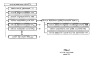
- FIG. 7 is a block diagram of vehicle parameter data 700 as relating to a vehicle attachment point 104 and/or attachment points 104 , 104 a , 104 b , etc.
- the vehicle parameter data 700 relates to coupling data for the vehicle attachment point 104 , and to dimensions of the vehicle 101 (see FIGS. 1-4 ).
- the vehicle parameter data 700 may include a vehicle width parameter 132 , a vehicle length parameters 134 , and a vehicle height parameter 136 .
- the vehicle parameter data 700 may include one or many vehicle attachment points 104 .
- a vehicle 101 may include a vehicle attachment point 104 , which may suspend a hammock from the at least one tether coupled to the vehicle attachment point 104 , and another tether to an anchor from another object (such as a tree, a rock, another vehicle, etc.).
- the vehicle 101 may also include another similar vehicle attachment point elsewhere on the vehicle, or a roof mounted configuration 400 (see FIG. 3 ).
- the vehicle parameter data 700 would include corresponding parameters for each of the vehicle attachment points.
- the vehicle parameter data 700 may include identifiers for vehicle attachment point 104 , 104 a , and 104 b , which may be displayed graphically to a vehicle user for selection of one or all of the attachment points (in which event, the object 302 of FIG. 6 with the greatest relative footprint and associated vehicle attachment point would govern placement of the attachment vehicle point via the vehicle 101 ).
- the vehicle attachment point 104 further includes a vehicle attachment point elevation parameter 138 , a vehicle attachment point width parameter 140 , and a vehicle attachment point distance parameter 150 .
- a sensor input device may be co-located with the vehicle attachment point, in which the distance parameter 150 may effective be a null value.
- the parameters may further include such relational attachment point data.
- the data 700 conveys the distance from the ground of an attachment point (parameter 138 ), the extent the attachment point may extend beyond or be contained within a vehicle skin (parameter 140 ), and the relative location of the vehicle attachment point 104 to a respective input sensor device 102 (see, e.g., FIG. 1 ) for determination of a vehicle distance value with respect to a selected object (see FIG. 6 ).
- the attachment point 104 may include an object attachment 804 for attachment to a tether 304 of an object 302 , a vehicle attachment 806 for attachment to a vehicle 101 , and a force sensor device 802 therebetween.
- the vehicle attachment point 104 of FIG. 8 is to relay general force sensing at an attachment point 104 , with the understanding that various configurations may be deployed to provide an object attachment including a tensile force and/or flex force exertion to the attachment point 104 .
- the vehicle attachment 806 may receive a bolt at vehicle attachment 806 to mount to a vehicle frame, and in this manner may move freely about the bolt as well as detachably stowed when not in use. Further, the communication with a vehicle control unit 300 may occur wirelessly in such a context, via antenna 520 of the vehicle control unit 500 (see, e.g., FIGS. 1-5 ).
- the vehicle attachment 806 may be fixed to a vehicle frame or other such support surface, with the force sensor device 802 and object attachment 804 being removably secured to the cylinder rod of the vehicle attachment 806 by a pin assembly.
- a compact configuration may be accessed via a panel plate on the vehicle skin to access the object attachment 804 portion.
- Other such configurations may be implemented.
- the vehicle control unit 500 may access the force sensor device data 516 - 802 to provide the method and or device described herein, as well as to provide a tension force control value 808 .
- the vehicle attachment point 104 includes a force sensor device 802 , which may include a force sensing transducer aligned to register tensile forces (For cetension ) and flex forces (Force flex ) orthogonal to an axis-of-symmetry of the vehicle attachment point 104 .
- a force vector 803 and associated angle component ⁇ 803 may produce force sensor device data 516 - 802 .
- the data 516 - 802 may be received by the vehicle control unit 300 via the vehicle network 501 (see FIG. 5 ).
- the vehicle control unit 500 may sample the force sensor device data 516 - 802 to determine whether the at least one tether 304 of an object 302 is coupled to the vehicle attachment point 104 via the object attachment 804 .
- the vehicle control unit 500 may determine whether the force vector 803 and associated angle ⁇ 803 , via force sensor device data 516 - 802 , exceeds a predetermined threshold value of the object 302 and/or of the vehicle attachment point 104 .
- the vehicle control unit 500 receives the remote control signal 362 , via the antenna 520 , which may include a tension force control value 808 (see, e.g., FIGS. 1-5 ). Based on the tension force value 808 , a tension mechanism of the vehicle attachment point 104 may be adjusted, such as adjusting an effective length of the attachment point 104 , by rotating the tether 304 about a spindle-configuration of the vehicle attachment point 104 mounted within the void of object attachment 804 .
- a spindle of such sort may be operated on a hydraulic, gear-motor, ratchet and/or other mechanism to impart rotation to a spindle component or to increase/decrease a length of a vehicle attachment point 104 .
- the vehicle control unit 500 may sample the force sensor device data 802 to receive feedback on a tension level via the tether 304 .
- the tension level may be on a “fuzzy” logic basis, as suitable tensions levels may differ for different users.
- the force sensor device data may indicate a “very taut” value, a “somewhat taut” value, a slack value, etc.
- FIG. 9 is a block diagram of a vehicle control unit 500 , which includes a wireless communication interface 902 , a processor 904 , and memory 906 , that are communicatively coupled via a bus 908 .
- the processor 904 of the control unit 500 can be a conventional central processing unit or any other type of device, or multiple devices, capable of manipulating or processing information. As may be appreciated, processor 904 may be a single processing device or a plurality of processing devices. Such a processing device may be a microprocessor, micro-controller, digital signal processor, microcomputer, central processing unit, field programmable gate array, programmable logic device, state machine, logic circuitry, analog circuitry, digital circuitry, and/or any device that manipulates signals (analog and/or digital) based on hard coding of the circuitry and/or operational instructions.
- the memory and/or memory element 906 may be a single memory device, a plurality of memory devices, and/or embedded circuitry of the processing module 904 .
- Such a memory device may be a read-only memory, random access memory, volatile memory, non-volatile memory, static memory, dynamic memory, flash memory, cache memory, and/or any device that stores digital information.
- the memory 906 is capable of storing machine readable instructions such that the machine readable instructions can be accessed by the processor 904 .
- the machine readable instructions can comprise logic or algorithm(s) written in programming languages, and generations thereof, (e.g., 1GL, 2GL, 3GL, 4GL, or 5GL) such as, for example, machine language that may be directly executed by the processor 904 , or assembly language, object-oriented programming (OOP), scripting languages, microcode, etc., that may be compiled or assembled into machine readable instructions and stored on the memory 906 .
- the machine readable instructions may be written in a hardware description language (HDL), such as logic implemented via either a field-programmable gate array (FPGA) configuration or an application-specific integrated circuit (ASIC), or their equivalents. Accordingly, the methods and devices described herein may be implemented in any conventional computer programming language, as pre-programmed hardware elements, or as a combination of hardware and software components.
- HDL hardware description language
- FPGA field-programmable gate array
- ASIC application-specific integrated circuit
- the processing devices may be centrally located (e.g., directly coupled together via a wired and/or wireless bus structure) or may be distributed located (e.g., cloud computing via indirect coupling via a local area network and/or a wide area network).
- the processor 904 implements one or more of its functions via a state machine, analog circuitry, digital circuitry, and/or logic circuitry
- the memory and/or memory element storing the corresponding operational instructions may be embedded within, or external to, the circuitry comprising the state machine, analog circuitry, digital circuitry, and/or logic circuitry.
- the memory element stores, and the processor 904 executes, hard coded and/or operational instructions corresponding to at least some of the steps and/or functions illustrated in FIGS. 1-10 for positioning a vehicle attachment point and methods described herein.
- the wireless communication interface 902 generally governs and manages the vehicle user input data via the vehicle network 512 over the communication path 513 and/or wireless communication 140 and/or 337 .
- the wireless communication interface 902 also manages controller unit output and input data such as the announcement message 314 , the vehicle attachment point positional data 520 , sensor data 516 , and data requests/receipt, such as object data 312 .
- the sensor data 516 includes capturing of intensity or reflectivity returns of the environment surrounding the vehicle, and relative distance of vehicles.
- data captured by the sensor input devices 102 provided to the vehicle control unit 500 via the communication path 513 can be used by one or more of applications of the vehicle to determine the vehicle environment, and to also sense improved positional accuracy with distances relating to the vehicle attachment point or points.
- the vehicle control unit 500 functions to retrieve a plurality of object parameters relating to an object.
- the object includes at least one tether for removably coupling to a vehicle attachment point 104 .
- objects may include recreational and/or camping items, such as a hammock, a slack line, a dog-run tether, a clothes line, a tent, etc.
- the vehicle control unit 500 may determine a vehicle distance value relative to the vehicle attachment point to accommodate an object distance parameter retrieved from the plurality of object parameters that may be stored with memory 906 , or in the alternative received as object data 312 via a handheld mobile device 142 , an object tag 303 (see, e.g., FIGS. 3 and 4 ).
- the object distance parameter relates to a length of an object as extended from the vehicle attachment point, as attached to a vehicle.
- the object distance parameter relates to a suspension length of the hammock, including a level of “sag” to cradle a person.
- the vehicle control unit 500 may assess a vehicle environment via vehicle-based sensor devices, such as the sensor input devices 102 - 5 via sensor data 516 in the present simplified example.
- the vehicle control unit 500 may produce vehicle attachment point positional data for positioning the vehicle attachment point relative to a vehicle environment based on at least the object distance parameter and the vehicle distance value, as is discussed in detail with reference to FIGS. 1-10 .
- FIG. 10 shows an example process 1000 for positioning a vehicle attachment point.
- a vehicle control unit retrieves a plurality of object parameters relating to an object that includes at least one tether for removably coupling the object to a vehicle attachment point.
- An object may be considered to be an article of manufacture, OEM or otherwise in origin, that includes a tether that may couple to the vehicle attachment point for use of the object. Examples of objects may include a hammock, a slack line, a dog-run tether, a clothes line, a tent, etc.
- a vehicle distance value relative to the vehicle attachment point is determined for accommodating an object distance parameter of the plurality of object parameters. That is, relative to the vehicle attachment point, the distance being determined is for accommodating the object when coupled to the vehicle attachment point.
- the method at operation 1006 assesses a vehicle environment for the vehicle distance value and based on a plurality of vehicle parameters. The assessment may be based on a vehicle-based sensor device, which may be in a spaced-apart relation to the vehicle attachment point. As may be appreciated, such assessments and positioning may be based on sensor devices that had been allocated for autonomous and/or driver-assist driving functions, but alternatively, are temporarily repurposed for recreational and leisure pursuits.
- the vehicle control unit at operation 1010 produces vehicle attachment point positional data for positing the vehicle attachment point relative to the vehicle environment based on at least the object distance parameter and the vehicle distance value.
- the vehicle may continue moving forward or in reverse to assess a different vehicle environment resulting from the movement of the vehicle at operation 1006 until a suitable vehicle environment is found.
- the term “substantially” or “approximately,” as may be used herein, provides an industry-accepted tolerance to its corresponding term and/or relativity between items. Such an industry-accepted tolerance ranges from less than one percent to twenty percent and corresponds to, but is not limited to, component values, integrated circuit process variations, temperature variations, rise and fall times, and/or thermal noise. Such relativity between items range from a difference of a few percent to magnitude differences.
- Coupled includes direct coupling and indirect coupling via another component, element, circuit, or module where, for indirect coupling, the intervening component, element, circuit, or module does not modify the information of a signal but may adjust its current level, voltage level, and/or power level.
- inferred coupling (that is, where one element is coupled to another element by inference) includes direct and indirect coupling between two elements in the same manner as “coupled.”
- the term “compares favorably,” as may be used herein, indicates that a comparison between two or more elements, items, signals, et cetera, provides a desired relationship. For example, when the desired relationship is that a first signal has a greater magnitude than a second signal, a favorable comparison may be achieved when the magnitude of the first signal is greater than that of the second signal, or when the magnitude of the second signal is less than that of the first signal.
- a module includes a functional block that is implemented in hardware, software, and/or firmware that performs one or more functions such as the processing of an input signal to produce an output signal.
- a module may contain submodules that themselves are modules.
Landscapes
- Physics & Mathematics (AREA)
- Engineering & Computer Science (AREA)
- General Physics & Mathematics (AREA)
- Electromagnetism (AREA)
- Radar, Positioning & Navigation (AREA)
- Remote Sensing (AREA)
- Computer Networks & Wireless Communication (AREA)
- Automation & Control Theory (AREA)
- Chemical & Material Sciences (AREA)
- Analytical Chemistry (AREA)
- Transportation (AREA)
- Mechanical Engineering (AREA)
- Aviation & Aerospace Engineering (AREA)
- Mathematical Physics (AREA)
- Traffic Control Systems (AREA)
Abstract
Description
Claims (20)
Priority Applications (1)
| Application Number | Priority Date | Filing Date | Title |
|---|---|---|---|
| US15/381,639 US10317909B2 (en) | 2016-12-16 | 2016-12-16 | Vehicle attachment point positioning in relation to a vehicle environment |
Applications Claiming Priority (1)
| Application Number | Priority Date | Filing Date | Title |
|---|---|---|---|
| US15/381,639 US10317909B2 (en) | 2016-12-16 | 2016-12-16 | Vehicle attachment point positioning in relation to a vehicle environment |
Publications (2)
| Publication Number | Publication Date |
|---|---|
| US20180173241A1 US20180173241A1 (en) | 2018-06-21 |
| US10317909B2 true US10317909B2 (en) | 2019-06-11 |
Family
ID=62561587
Family Applications (1)
| Application Number | Title | Priority Date | Filing Date |
|---|---|---|---|
| US15/381,639 Active 2037-07-13 US10317909B2 (en) | 2016-12-16 | 2016-12-16 | Vehicle attachment point positioning in relation to a vehicle environment |
Country Status (1)
| Country | Link |
|---|---|
| US (1) | US10317909B2 (en) |
Citations (13)
| Publication number | Priority date | Publication date | Assignee | Title |
|---|---|---|---|---|
| US3021852A (en) * | 1959-04-10 | 1962-02-20 | Norman A Hoffman | Car top tent |
| US3056415A (en) * | 1959-07-17 | 1962-10-02 | Ray F Nimmo | Collapsible tent for automobiles |
| US4522441A (en) * | 1983-09-06 | 1985-06-11 | Allison Dallas K | Collapsible shelter |
| US5738130A (en) | 1997-01-06 | 1998-04-14 | Thomas; William | Vehicle supported tent |
| US6505873B1 (en) | 2000-12-06 | 2003-01-14 | Alfa Leisure, Inc. | System for preventing damage to recreational vehicle slide-outs |
| US20070126395A1 (en) * | 2005-12-01 | 2007-06-07 | Suchar Michael J | Automatic recharging docking station for electric vehicles and hybrid vehicles |
| US7309075B2 (en) * | 2004-06-23 | 2007-12-18 | Ramsey J Edward | Trailer alignment device |
| US8033349B2 (en) * | 2009-03-12 | 2011-10-11 | Ford Global Technologies, Inc. | Auto-seek electrical connection for a plug-in hybrid electric vehicle |
| US8234010B2 (en) * | 2010-02-16 | 2012-07-31 | Deere & Company | Tethered robot positioning |
| US20120261516A1 (en) * | 2011-04-15 | 2012-10-18 | Patrick Gilliland | Ladar sensor for landing, docking and approach |
| US8552836B2 (en) * | 2008-10-20 | 2013-10-08 | The Boeing Company | System and method for coupling a component to a vehicle |
| US20150102154A1 (en) * | 2013-10-15 | 2015-04-16 | Elwha Llc | Motor vehicle with captive aircraft |
| US9072368B2 (en) | 2013-05-24 | 2015-07-07 | John H. Mueller | Supporting a hammock on a vehicle |
-
2016
- 2016-12-16 US US15/381,639 patent/US10317909B2/en active Active
Patent Citations (13)
| Publication number | Priority date | Publication date | Assignee | Title |
|---|---|---|---|---|
| US3021852A (en) * | 1959-04-10 | 1962-02-20 | Norman A Hoffman | Car top tent |
| US3056415A (en) * | 1959-07-17 | 1962-10-02 | Ray F Nimmo | Collapsible tent for automobiles |
| US4522441A (en) * | 1983-09-06 | 1985-06-11 | Allison Dallas K | Collapsible shelter |
| US5738130A (en) | 1997-01-06 | 1998-04-14 | Thomas; William | Vehicle supported tent |
| US6505873B1 (en) | 2000-12-06 | 2003-01-14 | Alfa Leisure, Inc. | System for preventing damage to recreational vehicle slide-outs |
| US7309075B2 (en) * | 2004-06-23 | 2007-12-18 | Ramsey J Edward | Trailer alignment device |
| US20070126395A1 (en) * | 2005-12-01 | 2007-06-07 | Suchar Michael J | Automatic recharging docking station for electric vehicles and hybrid vehicles |
| US8552836B2 (en) * | 2008-10-20 | 2013-10-08 | The Boeing Company | System and method for coupling a component to a vehicle |
| US8033349B2 (en) * | 2009-03-12 | 2011-10-11 | Ford Global Technologies, Inc. | Auto-seek electrical connection for a plug-in hybrid electric vehicle |
| US8234010B2 (en) * | 2010-02-16 | 2012-07-31 | Deere & Company | Tethered robot positioning |
| US20120261516A1 (en) * | 2011-04-15 | 2012-10-18 | Patrick Gilliland | Ladar sensor for landing, docking and approach |
| US9072368B2 (en) | 2013-05-24 | 2015-07-07 | John H. Mueller | Supporting a hammock on a vehicle |
| US20150102154A1 (en) * | 2013-10-15 | 2015-04-16 | Elwha Llc | Motor vehicle with captive aircraft |
Non-Patent Citations (2)
| Title |
|---|
| Eagles Nest Outfitters Inc., Roadie Hammock Stand, (www.eaglesnestoutfittersinc.com/product/ENO-ROADIE.html) (undated). |
| Unknown, "Finally got to use the whitson rack hammock mounts," web post, (https://www.reddit.com/r/4Runner/comments/3q827a/finally_got_to_use_the_whitson_rack_hammock_mounts/) (undated). |
Also Published As
| Publication number | Publication date |
|---|---|
| US20180173241A1 (en) | 2018-06-21 |
Similar Documents
| Publication | Publication Date | Title |
|---|---|---|
| US10606268B2 (en) | Vehicle control device mounted on vehicle and method for controlling the vehicle | |
| US10992860B2 (en) | Dynamic seam adjustment of image overlap zones from multi-camera source images | |
| US10166996B2 (en) | Systems and methods for adaptively communicating notices in a vehicle | |
| US10030991B2 (en) | Systems and methods for adjusting a contour of a vehicle based on a protrusion | |
| US10371797B1 (en) | Systems and methods for enhancing target detection | |
| US9636981B2 (en) | Systems and methods for altering one or more vehicle functions | |
| EP3424756A1 (en) | Integrated vehicle monitoring system | |
| US10611378B2 (en) | Systems and methods for operating a vehicle on a roadway | |
| US20180050664A1 (en) | Operational mode change based on vehicle occupancy for an autonomous vehicle | |
| US10471927B1 (en) | Tethered airbags | |
| US20180022278A1 (en) | System and method for enhancing vehicle environment perception | |
| US20200164770A1 (en) | Vehicle control apparatus disposed in vehicle and control method of vehicle | |
| CN107215276B (en) | Vehicle DAS (Driver Assistant System) and its control method | |
| US11807257B2 (en) | Sensing interactions with unpermitted components within a vehicle | |
| CN114556253A (en) | Sensor field of view in self-driving vehicles | |
| US20180211527A1 (en) | Systems and methods for communicating notices within a vehicle using a mobile device | |
| US10946710B2 (en) | Systems and methods for alerting drivers of excessive tongue weight | |
| US10317909B2 (en) | Vehicle attachment point positioning in relation to a vehicle environment | |
| US11262562B2 (en) | Infrared camera module cover | |
| US11200476B2 (en) | Cargo tracking systems and methods | |
| CN116797764A (en) | System and method for displaying infrastructure information on an augmented reality display | |
| US20230168091A1 (en) | Power Management Apparatus and Vehicle Having the Same | |
| DE102022127003A1 (en) | METHOD AND SYSTEM FOR VALIDATING THE PERFORMANCE OF AN AUTONOMOUS VEHICLE USING NEARBY TRAFFIC PATTERNS | |
| US20220388464A1 (en) | Sensing the ingress of water into a vehicle | |
| US11386874B2 (en) | System for performing image stabilization of a display in a vehicle |
Legal Events
| Date | Code | Title | Description |
|---|---|---|---|
| AS | Assignment |
Owner name: TOYOTA MOTOR ENGINEERING & MANUFACTURING NORTH AME Free format text: ASSIGNMENT OF ASSIGNORS INTEREST;ASSIGNORS:HURST, KAMERON R.;HALL, JONATHAN C.;GRANT, CASSANDRA R.;AND OTHERS;SIGNING DATES FROM 20161205 TO 20161212;REEL/FRAME:040885/0936 |
|
| AS | Assignment |
Owner name: TOYOTA MOTOR ENGINEERING & MANUFACTURING NORTH AME Free format text: CORRECTIVE ASSIGNMENT TO CORRECT THE INCORRECT APPLICATION NUMBER OF 15/377841 PREVIOUSLY RECORDED ON REEL 040885 FRAME 0936. ASSIGNOR(S) HEREBY CONFIRMS THE ASSIGNMENT;ASSIGNORS:HURST, KAMERON R.;HALL, JONATHAN C.;GRANT, CASSANDRA R.;AND OTHERS;SIGNING DATES FROM 20161205 TO 20161212;REEL/FRAME:042098/0182 |
|
| AS | Assignment |
Owner name: TOYOTA MOTOR ENGINEERING & MANUFACTURING NORTH AMERICA, INC., TEXAS Free format text: CHANGE OF ADDRESS;ASSIGNOR:TOYOTA MOTOR ENGINEERING & MANUFACTURING NORTH AMERICA, INC.;REEL/FRAME:047688/0784 Effective date: 20181128 Owner name: TOYOTA MOTOR ENGINEERING & MANUFACTURING NORTH AME Free format text: CHANGE OF ADDRESS;ASSIGNOR:TOYOTA MOTOR ENGINEERING & MANUFACTURING NORTH AMERICA, INC.;REEL/FRAME:047688/0784 Effective date: 20181128 |
|
| STPP | Information on status: patent application and granting procedure in general |
Free format text: NOTICE OF ALLOWANCE MAILED -- APPLICATION RECEIVED IN OFFICE OF PUBLICATIONS |
|
| STPP | Information on status: patent application and granting procedure in general |
Free format text: PUBLICATIONS -- ISSUE FEE PAYMENT VERIFIED |
|
| STPP | Information on status: patent application and granting procedure in general |
Free format text: AWAITING TC RESP, ISSUE FEE PAYMENT VERIFIED |
|
| STCF | Information on status: patent grant |
Free format text: PATENTED CASE |
|
| MAFP | Maintenance fee payment |
Free format text: PAYMENT OF MAINTENANCE FEE, 4TH YEAR, LARGE ENTITY (ORIGINAL EVENT CODE: M1551); ENTITY STATUS OF PATENT OWNER: LARGE ENTITY Year of fee payment: 4 |