US10312978B2 - Wireless transceiver station with performs multi-path reciprocity calibration with multiple reference antennas - Google Patents
Wireless transceiver station with performs multi-path reciprocity calibration with multiple reference antennas Download PDFInfo
- Publication number
- US10312978B2 US10312978B2 US16/036,372 US201816036372A US10312978B2 US 10312978 B2 US10312978 B2 US 10312978B2 US 201816036372 A US201816036372 A US 201816036372A US 10312978 B2 US10312978 B2 US 10312978B2
- Authority
- US
- United States
- Prior art keywords
- antenna
- reciprocity
- antennas
- coefficient
- antenna pair
- Prior art date
- Legal status (The legal status is an assumption and is not a legal conclusion. Google has not performed a legal analysis and makes no representation as to the accuracy of the status listed.)
- Active
Links
- 230000004044 response Effects 0.000 claims abstract description 67
- 238000000034 method Methods 0.000 claims description 49
- 238000012935 Averaging Methods 0.000 claims description 6
- 238000005259 measurement Methods 0.000 description 25
- 238000004891 communication Methods 0.000 description 12
- 238000010586 diagram Methods 0.000 description 12
- 238000013459 approach Methods 0.000 description 11
- 238000003491 array Methods 0.000 description 7
- 230000005540 biological transmission Effects 0.000 description 6
- 230000001413 cellular effect Effects 0.000 description 5
- 239000000306 component Substances 0.000 description 5
- 235000008694 Humulus lupulus Nutrition 0.000 description 4
- 239000000969 carrier Substances 0.000 description 4
- 230000000694 effects Effects 0.000 description 4
- 238000012545 processing Methods 0.000 description 4
- 230000008859 change Effects 0.000 description 3
- 230000009977 dual effect Effects 0.000 description 3
- 230000006870 function Effects 0.000 description 3
- 230000015654 memory Effects 0.000 description 3
- 230000002441 reversible effect Effects 0.000 description 3
- 230000002238 attenuated effect Effects 0.000 description 2
- 230000008901 benefit Effects 0.000 description 2
- 238000004364 calculation method Methods 0.000 description 2
- 239000008358 core component Substances 0.000 description 2
- 238000010295 mobile communication Methods 0.000 description 2
- 230000009467 reduction Effects 0.000 description 2
- 230000011664 signaling Effects 0.000 description 2
- 230000009286 beneficial effect Effects 0.000 description 1
- 238000013500 data storage Methods 0.000 description 1
- 230000006735 deficit Effects 0.000 description 1
- 238000013461 design Methods 0.000 description 1
- 230000002349 favourable effect Effects 0.000 description 1
- 238000012986 modification Methods 0.000 description 1
- 230000004048 modification Effects 0.000 description 1
- 238000005457 optimization Methods 0.000 description 1
- 230000000737 periodic effect Effects 0.000 description 1
- 230000000135 prohibitive effect Effects 0.000 description 1
- 239000007787 solid Substances 0.000 description 1
Images
Classifications
-
- H—ELECTRICITY
- H04—ELECTRIC COMMUNICATION TECHNIQUE
- H04B—TRANSMISSION
- H04B17/00—Monitoring; Testing
- H04B17/0082—Monitoring; Testing using service channels; using auxiliary channels
- H04B17/0085—Monitoring; Testing using service channels; using auxiliary channels using test signal generators
-
- H—ELECTRICITY
- H04—ELECTRIC COMMUNICATION TECHNIQUE
- H04B—TRANSMISSION
- H04B7/00—Radio transmission systems, i.e. using radiation field
- H04B7/02—Diversity systems; Multi-antenna system, i.e. transmission or reception using multiple antennas
- H04B7/04—Diversity systems; Multi-antenna system, i.e. transmission or reception using multiple antennas using two or more spaced independent antennas
- H04B7/0413—MIMO systems
- H04B7/0417—Feedback systems
-
- H—ELECTRICITY
- H01—ELECTRIC ELEMENTS
- H01Q—ANTENNAS, i.e. RADIO AERIALS
- H01Q1/00—Details of, or arrangements associated with, antennas
- H01Q1/12—Supports; Mounting means
- H01Q1/22—Supports; Mounting means by structural association with other equipment or articles
- H01Q1/24—Supports; Mounting means by structural association with other equipment or articles with receiving set
- H01Q1/241—Supports; Mounting means by structural association with other equipment or articles with receiving set used in mobile communications, e.g. GSM
-
- H—ELECTRICITY
- H04—ELECTRIC COMMUNICATION TECHNIQUE
- H04B—TRANSMISSION
- H04B1/00—Details of transmission systems, not covered by a single one of groups H04B3/00 - H04B13/00; Details of transmission systems not characterised by the medium used for transmission
- H04B1/38—Transceivers, i.e. devices in which transmitter and receiver form a structural unit and in which at least one part is used for functions of transmitting and receiving
- H04B1/40—Circuits
-
- H—ELECTRICITY
- H04—ELECTRIC COMMUNICATION TECHNIQUE
- H04B—TRANSMISSION
- H04B17/00—Monitoring; Testing
- H04B17/10—Monitoring; Testing of transmitters
- H04B17/11—Monitoring; Testing of transmitters for calibration
- H04B17/12—Monitoring; Testing of transmitters for calibration of transmit antennas, e.g. of the amplitude or phase
-
- H—ELECTRICITY
- H04—ELECTRIC COMMUNICATION TECHNIQUE
- H04B—TRANSMISSION
- H04B17/00—Monitoring; Testing
- H04B17/10—Monitoring; Testing of transmitters
- H04B17/11—Monitoring; Testing of transmitters for calibration
- H04B17/14—Monitoring; Testing of transmitters for calibration of the whole transmission and reception path, e.g. self-test loop-back
-
- H—ELECTRICITY
- H04—ELECTRIC COMMUNICATION TECHNIQUE
- H04L—TRANSMISSION OF DIGITAL INFORMATION, e.g. TELEGRAPHIC COMMUNICATION
- H04L1/00—Arrangements for detecting or preventing errors in the information received
- H04L1/0001—Systems modifying transmission characteristics according to link quality, e.g. power backoff
- H04L1/0009—Systems modifying transmission characteristics according to link quality, e.g. power backoff by adapting the channel coding
-
- H—ELECTRICITY
- H04—ELECTRIC COMMUNICATION TECHNIQUE
- H04B—TRANSMISSION
- H04B7/00—Radio transmission systems, i.e. using radiation field
- H04B7/02—Diversity systems; Multi-antenna system, i.e. transmission or reception using multiple antennas
- H04B7/04—Diversity systems; Multi-antenna system, i.e. transmission or reception using multiple antennas using two or more spaced independent antennas
- H04B7/0413—MIMO systems
Definitions
- the New Radio (NR) definition in 3GPP (3 rd Generation Partnership Project) for mobile communication systems will encompass a variety of deployment scenarios envisioned for 5G (fifth generation) mobile communication systems.
- MIMO (multiple input, multiple output) communication systems can be used for 5G TDD (time division duplex) air interfaces.
- massive MIMO reciprocity-based TDD air interfaces allow for symbol-level switching and potential configurability that in turn allow for features to support various aspects of 5G air interfaces, for example, enhanced Mobile BroadBand (eMBB), massive Machine Type Communications (mMTC) and Ultra-Reliable and Low Latency Communications (URLLC).
- eMBB enhanced Mobile BroadBand
- mMTC massive Machine Type Communications
- URLLC Ultra-Reliable and Low Latency Communications
- TDD time division duplex
- Precoding ensures that multiple mobile stations, with only a few antennas each, receive downlink signals without multi-user interference.
- radio components are used for uplink and downlink transmission at the base station. Their impact needs to be calibrated accurately (reciprocity calibration) such that uplink channel information can be used for downlink precoding. Inaccurate calibration results in multi-user interference in the downlink, which results in reduced data rates.
- Calibration can be implemented internally within the base station array by measuring the channel between individual base station array antenna elements. These measurements need to be accurate. Antenna array calibration accuracy can be severely reduced if the link between a certain antenna element and a reference antenna element is attenuated, for instance, due to array geometry.
- the present invention provides a wireless transceiver station that includes M antennas connected to radio transceivers and a processor programmed to designate an antenna of the M antennas as a target reference antenna.
- the processor is further programmed to: define N distinct paths from the antenna m to the target reference antenna through zero or more intermediate reference antennas of the M antennas, wherein N for the antenna m is two or more; wherein each of the N distinct paths has a distinct associated set of one or more antenna pairs of the M antennas; for each antenna pair of the sets of antenna pairs, estimate an effective forward and backward channel response by sending calibration pilots forth and back between the antenna pair and calculate a reciprocity coefficient for the antenna pair using the estimated channel responses; for each path of the N distinct paths, calculate a reciprocity coefficient estimate using the reciprocity coefficients calculated for the set of antenna pairs associated with the path; and combine the N calculated reciprocity coefficient estimates to produce a final reciprocity coefficient estimate for antenna pair (m, target reference antenna).
- the present invention provides a wireless transceiver station having M antennas connected to radio transceivers and a processor programmed to designate an antenna of the M antennas as a target reference antenna and to designate a subset of R antennas of the M antennas as reference antennas, where the target reference antenna is included in the subset, where R is at least two.
- the processor is programmed to define N distinct paths from the antenna m to the target reference antenna through zero or more of P distinct pairs of antennas (rr, rl) of the subset of R reference antennas, where P is at least one, where N for the antenna m is two or more.
- the processor is programmed to estimate an effective forward and backward channel response by sending calibration pilots forth and back between the antenna pair (m, r) and to calculate a single-hop reciprocity coefficient estimate for the antenna pair (m, r) using the estimated effective forward and backward channel responses for the antenna pair (m, r).
- the processor For each antenna pair (rr, rl) of the P distinct pairs of antennas (rr, rl) of the subset of R reference antennas, the processor is programmed to calculate one or more dual-hop reciprocity coefficient estimates for the antenna pair (rr, rl) through respective one or more antennas of the M antennas, where each respective antenna is distinct from rr and rl and to combine the single-hop reciprocity calibration coefficient estimate for the antenna pair (rr, rl) and the one or more dual-hop reciprocity calibration coefficient estimates for the antenna pair (rr, rl) to generate a combined reciprocity calibration coefficient estimate for the antenna pair (rr, rl).
- the processor For each antenna m of the M antennas, for each path of the N distinct paths for the antenna m, the processor is programmed to calculate a respective reciprocity coefficient estimate using the combined reciprocity calibration coefficient estimates for each of the antenna pairs (rr, rl) included in the path and the single-hop reciprocity coefficient estimate for the antenna pair (m, r), where antenna r is one of the antennas in antenna pair (rr, rl) included in the path. For each antenna m of the M antennas, the processor is programmed to combine the N respective reciprocity coefficient estimates to produce a final reciprocity coefficient estimate for antenna pair (m, target reference antenna).
- the present invention provides a method that includes designating an antenna of M antennas of a wireless transceiver station as a target reference antenna and for each antenna m of the M antennas other than the target reference antenna: defining N distinct paths from the antenna m to the target reference antenna through zero or more intermediate reference antennas of the M antennas, wherein N for the antenna m is two or more, wherein each of the N distinct paths has a distinct associated set of one or more antenna pairs of the M antennas; for each antenna pair of the sets of antenna pairs, estimating an effective forward and backward channel response by sending calibration pilots forth and back between the antenna pair and calculating a reciprocity coefficient for the antenna pair using the estimated channel responses; for each path of the N distinct paths, calculating a reciprocity coefficient estimate using the reciprocity coefficients calculated for the set of antenna pairs associated with the path; and combining the N calculated reciprocity coefficient estimates to produce a final reciprocity coefficient estimate for antenna pair (m, target reference antenna).
- the present invention provides a method that includes designating one antenna of the M antennas as a target reference antenna; designating a subset of R antennas of the M antennas as reference antennas, where the target reference antenna is included in the subset, where R is at least two; for each antenna m of the M antennas other than the target reference antenna, defining N distinct paths from the antenna m to the target reference antenna through zero or more of P distinct pairs of antennas (rr, rl) of the subset of R reference antennas, where P is at least one, where N for the antenna m is two or more; for at least each antenna pair (m, r) included in the N distinct paths for the M antennas, estimating an effective forward and backward channel response by sending calibration pilots forth and back between the antenna pair (m, r) and calculating a single-hop reciprocity coefficient estimate for the antenna pair (m, r) using the estimated effective forward and backward channel responses for the antenna pair (m, r); for each antenna pair (rr, rl)
- FIG. 1 is a block diagram illustrating an example embodiment for channel reciprocity associated with a wireless transceiver station with M antennas that provides a wireless MIMO communication system.
- FIG. 2 is a block diagram illustrating multi-path options for estimating reciprocity coefficients at a multi-antenna wireless transceiver station.
- FIG. 3 is a diagram illustrating an initial set of reference antennas used during initial calibration.
- FIG. 4 is a diagram of an antenna array similar to FIG. 3 and illustrating a reduced set of reference antennas relative to the initial set of reference antennas of FIG. 3 .
- FIG. 5 is a diagram of an example wireless transceiver station architecture with 3 distributed 8 ⁇ 8 antenna sub-arrays connected to a wireless transceiver station signal processing unit.
- FIGS. 6 through 14 are flowcharts illustrating operation of the wireless transceiver station of FIG. 5 .
- FIG. 15 is a diagram of antennas illustrating operation according to FIG. 12 to provide a highly reliable reciprocity coefficient estimate for a pair of reference antennas.
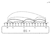
- FIG. 1 a block diagram illustrating an example embodiment for channel reciprocity associated with a wireless transceiver station 102 (e.g., a cellular base station, wireless router, or other wireless transceiver station), also referred to herein as a base station 102 , with M antennas 104 that provides a wireless MIMO communication system 100 is shown.
- An individual BS 102 antenna is referred to generically as antenna m.
- the MIMO base station 102 communicates through its M antennas 104 with multiple mobile stations (MS), or user equipment (UE) devices 106 , such as mobile handsets, that each have one or more antenna 108 , shown in total as K antennas in FIG. 1 .
- An individual MS 106 antenna 108 is referred to generically as antenna k.
- the need for reciprocity calibration will now be described.
- an example embodiment of a wireless MIMO communication system may use linear reciprocity-based pre-coding in the downlink to suppress downlink inter-user interference in Multi-User MIMO (MU-MIMO) operation mode.
- MU-MIMO Multi-User MIMO
- This approach assumes that the wireless MIMO channel between the base station (BS) and the mobile stations (MS) is reciprocal, which is valid under certain conditions.
- the effective channel response ⁇ tilde over (h) ⁇ between any two transceivers can be expressed as the product of the transmitter (TX) front end response t, the physical wireless channel responses h, and the receiver (RX) front end response r.
- a reciprocity calibration factor b m ⁇ k can be defined as the quotient between the channel responses of the effective forward channel and the effective backward channel given in equation (1.5).
- the reciprocity calibration factor only depends on the transmit and receive responses of the involved analog front ends. Of course, this also works in the reverse direction. Generally, we can write the relation shown in (1.8).
- Equations (1.7) and (1.8) are still not practical for a direct implementation in real systems since they would require measuring the reciprocity coefficients between every BS and MS antenna pair. For this, pilots would have been required also in the downlink to be sent from every BS antenna to every MS antenna as well as measurement feedback in the reverse directions. Moreover, since the mobile stations are typically not clock coupled to the base station, reciprocity measurements would have been needed frequently to compensate for related phase drifts.
- the reciprocity factor between base station antenna m and mobile station antenna k can be calculated per equation (1.11).
- ⁇ tilde over (h) ⁇ m ⁇ k DL ⁇ tilde over (h) ⁇ k ⁇ m UL ⁇ b m ⁇ r ⁇ b r ⁇ k (1.12)
- all downlink channel responses ⁇ tilde over (h) ⁇ m ⁇ k DL can be calculated up to a common factor b r ⁇ k .
- a common factor applied to all BS antennas does not change the beamforming characteristics, i.e., for all multi-user beamforming techniques using linear precoding it is sufficient to work with relative effective channel estimates as indicated in equation (1.13).
- the described reciprocity calibration method with one BS reference antenna works well as long as the reference antenna has a good wireless channel to all other base station antenna elements. Unfortunately, this cannot be always assured, especially if the base station works with a large number of antenna elements. In these cases, the method described above is extremely sensitive to the actual antenna arrangement. If one or more BS antenna elements m see a bad channel to the BS reference antenna r, the estimates of the related reciprocity coefficients b m ⁇ r may become unreliable. This can drastically reduce the multi-user downlink performance since also the derived estimates for ⁇ tilde over (h) ⁇ ′ m ⁇ k DL may be unreliable, which may affect calculation of the downlink pre-coding weights.
- Equation (1.15) can be further extended from using one intermediate reference antenna (dual-hop estimates) to using multiple intermediate reference antennas (multi-hop estimates). In a compact form this can be expressed as equation (1.16).
- n represents a specific set of antenna index pairs (a, b) which corresponds to the indices of all BS antenna pairs involved in one specific multi-hop calibration estimate from BS antenna m to target BS reference antenna r 1 .
- a, b the indices of all BS antenna pairs involved in one specific multi-hop calibration estimate from BS antenna m to target BS reference antenna r 1 .
- a 1 ⁇ ( m , r 3 ) , ( r 3 , r 2 ) , ( r 2 , r 1 ) ⁇ ( 1.17 ) b m ⁇ r 1
- equation (1.16) generally holds for every set n of BS antenna pair indices which describes a valid single-hop or multi-hop “connection,” or “path,” from a BS antenna m to the target reference antenna r 1 . It does not depend on the definition of additional reference antennas.
- b ⁇ m ⁇ r 1 arg ⁇ ⁇ min b ⁇ m ⁇ r 1
- the (noise-free) reciprocity coefficients b a ⁇ b between the different BS antennas are assumed to be constant complex factors. This implies that the reciprocity coefficients can be simply estimated in frequency-domain on a sub-carrier basis, which is the simplest way for the given OFDM based system. Sub-carrier wise estimation provides multiple estimates (one per sub-carrier i) for every reciprocity coefficient b a ⁇ b .
- Y a ⁇ b ⁇ ( i ) H ⁇ a ⁇ b ⁇ ( i ) ⁇ X p ⁇ ( i ) + N a ⁇ b ⁇ ( i ) for ⁇ ⁇ a ⁇ b ( 1.23 )
- Y b ⁇ a ⁇ ( i ) H ⁇ b ⁇ a ⁇ ( i ) ⁇ X p ⁇ ( i ) + N b ⁇ a ⁇ ( i ) for ⁇ ⁇ a ⁇ b ( 1.24 )
- a n ⁇ ( i ) ⁇ ⁇ ( a , b ) ⁇ A n ⁇ ⁇ b ⁇ a ⁇ b ⁇ ( i ) ( 1.28 )
- every additional intermediate reference antenna i.e., every additional hop
- every additional hop includes the noise effects of additional TX/RX front ends.
- additional hops are beneficial if the target antennas see a bad wireless channel between each other. Further, additional hops (exponentially) increase the number of estimation options per calibration parameter, which can increase the potential combining gains.
- a multi-stage estimation approach is an additional method to keep the computational effort of the reciprocity calibration at a reasonable level.
- the idea of the multi-stage approach is to hierarchically combine intermediate estimation results in such a way that the number of necessary calculations reduces from stage to stage.
- a set ⁇ r 1 . . . r r . . . r R ⁇ of R ⁇ M BS antennas is selected as reference antenna set.
- the selection is done in a way that the physical distance to the target reference antenna r 1 increases with the reference antenna index r, i.e., r 2 has the shortest distance to r 1 , r 3 the second shortest, and r R the longest distance.
- the reference antennas should be approximately equally distributed with the set of all BS antennas. If the BS antennas are grouped into different sub-systems, the reference antennas should be equally distributed to the different sub-systems.
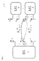
- FIG. 2 a block diagram illustrating multi-path options for estimating reciprocity coefficients at a multi-antenna wireless transceiver station 200 is shown.
- the wireless transceiver station 200 includes a plurality of antennas 104 , referred to generically as m, including reference antennas denoted r 1 , r 2 , r 3 , r 4 .
- FIG. 2 also illustrates multiple estimation options for estimating the reciprocity factor for the antenna pair (m, r 1 ), which includes the single-hop option from m to r1 as well as 3 different multi-hop options
- the detailed multi-stage calibration procedure variant 1 can be described as follows.
- the procedure in this section is almost identical to the procedure in the Detailed Multi-Stage Calibration Procedure—Variant 1 section. Only step 3 has been modified to average over frequency first, followed by the computation of the ratio. Also, the variance computation has been adapted accordingly. This variant provides additional savings with respect to the computational effort. Further the modified estimation step 3 may be more reliable.
- r is the set of all antenna pair indices describing the specific r-hop option.
- the mean single-hop estimates b m ⁇ r r are provided by calibration step 2, equation (1.49), and the mean combined estimates b r l ⁇ r l-1 are provided by calibration step 3, equation (1.55).
- the calibration coefficients change over time, for instance, as a matter of ambient or device temperature drifts.
- the calibration method presented in the previous section targets an accurate initial calibration with little prior information about the signal quality between individual antenna elements. The number of estimates obtained during this procedure can be prohibitive for fast re-calibration on run time. This section uses the method presented before to derive a faster means for re-calibration.
- the duration during which the array cannot be used depends on the number of channels which are measured between antenna elements during the calibration procedure.
- the initial procedure requires the estimation of the channels between all antenna elements in the array and all reference antennas.
- the time during which pilots for calibration are transmitted should be reduced as much as possible to increase the time for the actual data transmission and to minimize interference with the rest of the network.
- the following methods allow for an immediate reduction in calibration measurement time.
- Calibration coefficients are assumed to be frequency flat. In that case, a single parameter is to be estimated per antenna. This easily permits for using frequency orthogonal pilots and letting multiple antennas transmit at a time.
- the measurement calibration time can be reduced to a fixed duration by determining a reference antenna subset of fixed size by optimization according to the following criteria.
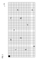
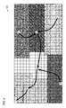
- FIG. 3 a diagram illustrating an initial set of reference antennas used during initial calibration is shown.
- FIG. 3 shows an array 300 of antenna elements arranged as 16 rows by 33 columns. Twelve of the antennas in the array are included in the initial set of reference antennas (shown in gray: row 2, col. 11; row 2, col. 24; row 4, col. 17; row 5, col. 5; row 6, col. 19; row 8, col. 11; row 8, col. 24; row 11, col. 5; row 12, col. 20; row 15, col. 29; row 16, col. 7), and the reference antennas are relatively evenly distributed throughout the array, as shown.
- a master reference antenna is shown in black in the top left corner (row 1, column 1).
- FIG. 4 a diagram of an antenna array 400 similar to FIG. 3 and illustrating a reduced set of reference antennas relative to the initial set of reference antennas of FIG. 3 is shown.
- a smaller subset of reference antennas is derived as shown in FIG. 4 .
- seven reference antennas are selected from the initial set.
- an association of each antenna element to a reference antenna ensures that each antenna element has a favorable connection to at least one reference antenna.
- the association is illustrated in FIG. 4 by different types of stipple and cross-hatching. Note that it is only required to measure the channel between the reference antenna and associated antenna elements but not between a reference antenna and non-associated antenna elements. This does not reduce the calibration measurement time but can help reduce the computational time to evaluate the channel measurements.
- the selection is derived in such a way that:
- the necessary channels between all reference antennas can be estimated. Also, the channel from reference antennas to all other reference antennas can be estimated during this time.
- one antenna element is active per subcarrier at each point in time (frequency orthogonal pilot design), as compared to 128 antenna elements which are active during normal operation. In that case, the overall transmitted power is reduced by a factor of 128. In addition, there is no beamforming gain as the transmitted signals are frequency orthogonal. That is, the interference to the remaining network is likely minimal.
- Massive MIMO Multiple Input Multiple Output
- TDD time division duplex
- Precoding ensures that multiple mobile stations, with only a few antennas each, receive downlink signals without multi-user interference.
- radio components are used for uplink and downlink transmission at the base station. Their impact needs to be calibrated accurately (reciprocity calibration) such that uplink channel information can be used for downlink precoding. Inaccurate calibration results in multi-user interference in the downlink, i.e., reduced data rates.
- Calibration can be implemented base station array-internally by measuring the channel between individual base station array antenna elements. These measurements need to be accurate. Accuracy can be severely reduced if the link between a certain antenna element and a reference antenna element is attenuated, for instance, due to array geometry.
- a robust means is provided to calibrate antenna arrays even if the link between some antenna elements and the reference antenna element is very weak.
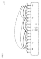
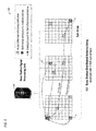
- FIG. 5 a diagram of an example wireless transceiver station architecture 500 with 3 distributed 8 ⁇ 8 antenna sub-arrays 504 connected to a wireless transceiver station signal processing unit 502 is shown.
- the antennas of the antenna array 504 may be exemplary of the antennas 104 of the base station 102 antenna arrays of FIGS. 1 and 2 .
- the processor 502 is programmed to perform the operations described here, e.g., above with respect to FIGS. 1 through 4 and below with respect to FIGS. 6 through 10 .
- Reciprocity calibration requires estimation of calibration coefficients between all antenna elements (see stippled antenna elements a, b, c in the example of FIG. 5 ) and a reference antenna to the mobile station (dark gray antenna in upper left-hand corner).
- the calibration coefficient between an antenna element and the reference antenna to the mobile station can be decomposed into a concatenation of calibration coefficients between the antenna element and multiple (array-internal) reference antennas (light gray antenna elements in the example of FIG. 5 ), referred to as a “path” (e.g., path from antenna element c through three array-internal reference antennas to the reference antenna to the mobile station in the upper left-hand corner).
- path e.g., path from antenna element c through three array-internal reference antennas to the reference antenna to the mobile station in the upper left-hand corner.
- each path can be used to estimate the calibration coefficient between the antenna element and the reference antenna to the mobile station.
- the estimates obtained from multiple different paths can be combined to enhance the accuracy of the estimated calibration coefficient.
- the impact of a weak direct path e.g. dotted path for antenna element c
- multi-path estimates which comprise strong links between all antenna elements (e.g., normal lines).
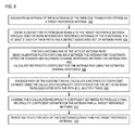
- FIG. 6 a flowchart illustrating operation of the wireless transceiver station 500 of FIG. 5 is shown. Flow begins at block 602 .
- the wireless transceiver station designates an antenna of the M antennas of the wireless transceiver station (e.g., an antenna 104 of an antenna array such as of the wireless transceiver station 102 of FIG. 1 or FIG. 2 or of wireless transceiver station 500 of FIG. 5 ) as a target reference antenna.
- an antenna of the M antennas of the wireless transceiver station e.g., an antenna 104 of an antenna array such as of the wireless transceiver station 102 of FIG. 1 or FIG. 2 or of wireless transceiver station 500 of FIG. 5 .
- the wireless transceiver station defines N distinct paths from an antenna m to the target reference antenna through zero or more intermediate antennas of the array.
- N is at least two for each antenna m, and the value of N may be different for a different antenna m.
- Each of the N paths has a distinct associated set of antenna pairs.
- the wireless transceiver station performs the following two steps for each antenna pair of the sets of antenna pairs defined at block 604 .
- the wireless transceiver station sends calibration pilots forth and back between the antenna pair to estimate effective forward and backward channel responses between the antenna pair.
- An example is according to equations (1.23) through (1.26).
- the wireless transceiver station also calculates a reciprocity coefficient for the antenna pair using the estimated channel responses.
- An example is according to equation (1.27). Flow proceeds to block 608 .
- the wireless transceiver station calculates a reciprocity coefficient estimate using the reciprocity coefficients calculated for the set of antenna pairs associated with the path.
- a reciprocity coefficient estimate is according to equation (1.18), (1.28), (1.45) or (1.58).
- the wireless transceiver station combines the N calculated reciprocity coefficient estimates to produce a final reciprocity coefficient estimate for antenna pair (m, target reference antenna).
- An example is according to equations (1.19) through (1.22), (1.29) through (1.34), (1.35) through (1.48), or (1.49) through (1.61).
- Flow proceeds to block 614 .
- the wireless transceiver station repeats blocks 604 through 612 for each of the M antennas, other than the target reference antenna, whose reciprocity calibration coefficient reduces to a unitary value.
- the combined reciprocity coefficient estimates may subsequently be used to perform reciprocity-based transmit precoding, transmit beamforming, and some types of receive beamforming.
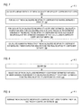
- FIG. 7 a flowchart illustrating operation of the wireless transceiver station 500 of FIG. 5 is shown. More specifically, FIG. 7 illustrates in more detail an embodiment of the operation of block 612 of FIG. 6 .
- Flow begins at block 702 .
- the wireless transceiver station calculates a mean for each of the N calculated reciprocity coefficient estimates.
- An example is according to equation (1.29). Flow proceeds to block 704 .
- the wireless transceiver station estimates a variance for each of the N calculated reciprocity coefficient estimates.
- An example is according to equation (1.31). Flow proceeds to block 706 .
- the wireless transceiver station calculates a respective weight.
- the weight is calculated as a ratio of a reciprocal of the estimated variance calculated at block 704 and a sum of reciprocals of the estimated variances of the N calculated reciprocity coefficient estimates.
- An example is according to equation (1.22), (1.33), (1.48), (1.56) or (1.61). Flow proceeds to block 708 .
- the wireless transceiver station calculates a sum of N products of the calculated reciprocity coefficient estimates and their respective weights to be the final reciprocity coefficient estimate.
- An example is according to equation (1.21), (1.32), (1.47), (1.55) or (1.60). Flow ends at block 708 .
- FIG. 8 a flowchart illustrating operation of the wireless transceiver station 500 of FIG. 5 is shown. More specifically, FIG. 8 illustrates in more detail an alternate embodiment of the operation of block 612 of FIG. 6 .
- Flow begins at block 702 as in FIG. 7 and further flows to block 704 as in FIG. 7 and then flows to block 806 of FIG. 8 .
- the wireless transceiver station selects one of the N calculated reciprocity coefficient estimates that has a minimum estimated variance (e.g., estimated at block 704 ) from among the calculated reciprocity coefficient estimates to be the final reciprocity coefficient estimate.
- a minimum estimated variance e.g., estimated at block 704
- An example is according to equation (1.20). Flow ends at block 806 .
- FIG. 9 a flowchart illustrating operation of the wireless transceiver station 500 of FIG. 5 is shown. More specifically, FIG. 8 illustrates in more detail an alternate embodiment of the operation of block 612 of FIG. 6 .
- Flow begins at block 902 .
- the wireless transceiver station averages the N calculated reciprocity coefficient estimates (e.g., the N reciprocity coefficient estimates calculated at block 608 of FIG. 6 ) to obtain the final reciprocity coefficient estimate.
- N calculated reciprocity coefficient estimates e.g., the N reciprocity coefficient estimates calculated at block 608 of FIG. 6
- An example is according to equation (1.19). Flow ends at block 902 .
- FIG. 10 a flowchart illustrating operation of the wireless transceiver station 500 of FIG. 5 is shown. More specifically, FIG. 10 illustrates in more detail an alternate embodiment of the operation at block 606 of FIG. 6 in which the wireless transceiver station is programmed to transmit and receive on multiple subcarriers, e.g., in an OFDM-based system. Flow begins at block 1002 .
- the wireless transceiver station performs the following two steps for each antenna pair of the sets of antenna pairs defined at block 604 .
- the wireless transceiver station sends calibration pilots forth and back between the antenna pair on each of a plurality of the multiple subcarriers to estimate an effective forward and backward channel response for the plurality of the multiple subcarriers.
- An example is according to equations (1.23) through (1.26).
- the wireless transceiver station also calculates a reciprocity coefficient for the antenna pair for each of the plurality of subcarriers using the effective forward and backward channel responses estimated for each of the plurality of subcarriers.
- Flow proceeds to block 1004 .
- the wireless transceiver station averages the calculated reciprocity coefficients over the plurality of subcarriers to obtain a mean reciprocity coefficient estimate for the antenna pair, which is the calculated reciprocity coefficient for the antenna pair (e.g., of block 606 ).
- a mean reciprocity coefficient estimate for the antenna pair which is the calculated reciprocity coefficient for the antenna pair (e.g., of block 606 ).
- An example is according to equation (1.49). Flow ends at block 1004 .
- FIG. 11 a flowchart illustrating operation of the wireless transceiver station 500 of FIG. 5 is shown. More specifically, FIG. 11 illustrates in more detail an alternate embodiment of the operation at block 608 of FIG. 6 in which the wireless transceiver station is programmed to transmit and receive on multiple subcarriers, e.g., in an OFDM-based system, as in FIG. 10 .
- Flow begins at block 1102 .
- the wireless transceiver station calculates the reciprocity coefficient estimate using the obtained mean reciprocity coefficient estimate for the set of antenna pairs associated with the path.
- Equation (1.58) provides an example of calculating a reciprocity coefficient estimate using mean reciprocity coefficient estimates for a set of antenna pairs associated with a path.
- the used mean reciprocity coefficient estimates are determined in the manner described with respect to steps 2 and 3 of the section Detailed Multi-Stage Calibration Procedure—Variant 2
- the used mean reciprocity coefficient estimates are not limited to such but may instead be calculated in other manners. Flow ends at block 1102 .
- FIG. 12 a flowchart illustrating operation of the wireless transceiver station 500 of FIG. 5 is shown.
- the embodiment described in FIG. 12 is similar in many ways to portions of the description in the section Detailed Multi-Stage Calibration Procedure—Variant 2.
- Flow begins at block 1202 .
- the wireless transceiver station designates an antenna of the M antennas of the wireless transceiver station (e.g., an antenna 104 of an antenna array such as of the wireless transceiver station 102 of FIG. 1 or FIG. 2 or of wireless transceiver station 500 of FIG. 5 ) as a target reference antenna.
- an antenna of the M antennas of the wireless transceiver station e.g., an antenna 104 of an antenna array such as of the wireless transceiver station 102 of FIG. 1 or FIG. 2 or of wireless transceiver station 500 of FIG. 5 .
- the wireless transceiver station designates a subset of R antennas of the M antennas as reference antennas.
- the target reference antenna is included in the subset.
- R is at least two.
- the wireless transceiver station defines N distinct paths from the antenna m to the target reference antenna through zero or more of P distinct pairs of antennas (r r , r l ) of the subset of R reference antennas.
- P is at least one.
- N for the antenna m is two or more, and the value of N may be different for a different antenna m.
- the wireless transceiver station performs the following two actions. First, (A) the wireless transceiver station estimates an effective forward and backward channel response by sending calibration pilots forth and back between the antenna pair (m, r). An example is according to equations (1.23) through (1.26). Second, (B) the wireless transceiver station calculates a single-hop reciprocity coefficient estimate for the antenna pair (m, r) using the estimated effective forward and backward channel responses for the antenna pair (m, r). An example is according to equation (1.27). Flow proceeds to block 1212 .
- the wireless transceiver station performs the following two actions. First, (A) the wireless transceiver station calculates one or more dual-hop reciprocity coefficient estimates for the antenna pair (r r , r l ) through respective one or more antennas of the M antennas, where each respective antenna is distinct from r r and r l .
- An example is according to equation (1.52).
- the wireless transceiver station combines the single-hop reciprocity calibration coefficient estimate for the antenna pair (r r , r l ) and the one or more dual-hop reciprocity calibration coefficient estimates for the antenna pair (r r , r l ) to generate a combined reciprocity calibration coefficient estimate for the antenna pair (r r , r l ).
- An example is according to equation (1.55).
- Flow proceeds to block 1214 .
- the wireless transceiver station performs the following two actions. First, the wireless transceiver station, for each path of the N distinct paths for the antenna m, calculates a respective reciprocity coefficient estimate using the combined reciprocity calibration coefficient estimates for each of the antenna pairs (r r , r l ) included in the path and the single-hop reciprocity coefficient estimate for the antenna pair (m, r), where antenna r is one of the antennas in antenna pair (r r , r l ) included in the path. An example is according to equation (1.58). Second, the wireless transceiver station combines the N respective reciprocity coefficient estimates to produce a final reciprocity coefficient estimate for antenna pair (m, target reference antenna). An example is according to equation (1.60). Flow ends at block 1214 .
- FIG. 13 a flowchart illustrating operation of the wireless transceiver station 500 of FIG. 5 is shown. More specifically, FIG. 13 illustrates in more detail an alternate embodiment of the operation at part (B) of block 1208 of FIG. 12 in which the wireless transceiver station is programmed to transmit and receive on multiple subcarriers, e.g., in an OFDM-based system.
- Flow begins at block 1302 .
- the wireless transceiver station estimates an effective forward and backward channel response for a plurality of the multiple subcarriers by sending calibration pilots forth and back between the antenna m and the antenna r on each of the plurality of subcarriers.
- An example is according to equations (1.23) through (1.26). Flow proceeds to block 1304 .
- the wireless transceiver station calculates a reciprocity coefficient for the antenna pair (m, r) for each of the plurality of subcarriers using the effective forward and backward channel responses estimated for each of the plurality of subcarriers.
- a reciprocity coefficient for the antenna pair (m, r) for each of the plurality of subcarriers using the effective forward and backward channel responses estimated for each of the plurality of subcarriers.
- An example is according to equation (1.27). Flow proceeds to block 1306 .
- the wireless transceiver station averages the calculated reciprocity coefficients of the antenna pair (m, r) over the plurality of subcarriers to obtain the single-hop reciprocity coefficient estimate for the antenna pair (m, r).
- An example is according to equation (1.49). Flow ends at block 1306 .
- FIG. 14 a flowchart illustrating operation of the wireless transceiver station 500 of FIG. 5 is shown. More specifically, FIG. 14 illustrates in more detail an alternate embodiment of the operation at part (B) of block 1212 of FIG. 12 . Flow begins at block 1402 .
- the wireless transceiver station calculates a respective weight.
- An example is according to equation (1.56). Flow proceeds to block 1404 .
- the wireless transceiver station calculates a sum of products of the single-hop reciprocity calibration coefficient estimate for the antenna pair (r r , r l ) and the one or more dual-hop reciprocity calibration coefficient estimates for the antenna pair (r r , r l ) and their respective weights to produce the combined reciprocity calibration coefficient estimate for the antenna pair (r r , r l ).
- An example is according to equation (1.55).
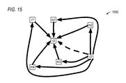
- FIG. 15 a diagram of antennas illustrating operation according to FIG. 12 to provide a highly reliable reciprocity coefficient estimate for a pair of reference antennas is shown.
- FIG. 15 illustrates three reference antennas, denoted r1, r2 and r3, and four non-reference antennas, denoted m1, m2, m3 and m4. More specifically, FIG. 15 illustrates the generation of a highly reliable reciprocity coefficient estimate for the antenna pair (r 2 r 3 ) through the combining of single-hop and dual-hop reciprocity coefficient estimates, e.g., according to equation 1.55 and/or block 1212 of FIG. 12 . A single-hop path between r2 and r3 is shown with a dashed arrow.
- multiple dual-hop paths between r2 and r3 through other antennas are shown with solid arrows. More specifically, five dual hop paths are shown between r2 and r3 through m1, m2, m3, m4 and r1.
- the reciprocity coefficient estimates for these single and dual hop paths may be calculated by equation (1.52), for example.
- the single-hop and dual-hop estimates may be combined, e.g., according to equation (1.55), to provide a more reliable reciprocity coefficient estimate for reference antenna pair (r 2 , r 3 ) than an embodiment in which only the single-hop path between reference antennas r2 and r3 is used to calculate the coefficient, particularly if the reference antenna pair (r2, r3) sees a bad wireless channel directly between them.
- this may provide a more reliable final reciprocity coefficient estimate for antenna pair (m, target reference antenna) that has one or more of its N paths through antenna pair (r2, r3) and therefore uses the reciprocity coefficient estimate for reference antenna pair (r2, r3) since it is likely the weight associated with the bad single-hop estimate will be relatively small and the weight associated with the good dual hop estimates will be relatively large due to the use of the variances, thereby reducing the effect of the bad wireless channel between antenna r2 and r3 in the combined weighted sum, e.g., of equation (1.55).
- embodiments are described for estimation of reciprocity coefficients for a multi-antenna cellular base station, other embodiments are contemplated for estimation of reciprocity coefficients for any multi-antenna transceiver system in an efficient and reliable way without a priori knowledge of which antenna pairs have a good connection and which do not.
- the method and systems are applicable to all multi-antenna techniques that rely on the reciprocity calibration of the antenna elements of a multi-antenna transceiver system. Such techniques can be reciprocity-based transmit precoding, transmit beamforming, and some types of receive beamforming.
- massive MIMO communication systems can be used for 5G dynamic TDD (time division duplex) air interfaces.
- the 5G (5 th generation) mobile telecommunications system is able to span a wide variety of deployment scenarios (e.g., Rural, Urban Macro, Dense Urban, Indoor, etc.) in a flexible and scalable manner.
- massive MIMO reciprocity-based TDD air interfaces allow for symbol-level switching and potential configurability that in turn allow for features to support three primary aspects of 5G air interfaces, namely enhanced Mobile BroadBand (eMBB), massive Machine Type Communications (mMTC) and Ultra-Reliable and Low Latency Communications (URLLC).
- eMBB enhanced Mobile BroadBand
- mMTC massive Machine Type Communications
- URLLC Ultra-Reliable and Low Latency Communications
- the functional blocks, components, systems, devices, and/or circuitry described herein can be implemented using hardware, software, or a combination of hardware and software.
- the disclosed embodiments can be implemented using one or more programmable integrated circuits that are programmed to perform the functions, tasks, methods, actions, and/or other operational features described herein for the disclosed embodiments.
- the one or more programmable integrated circuits can include, for example, one or more processors and/or PLDs (programmable logic devices).
- the one or more processors can be, for example, one or more central processing units (CPUs), controllers, microcontrollers, microprocessors, hardware accelerators, ASICs (application specific integrated circuit), and/or other integrated processing devices.
- the one or more PLDs can be, for example, one or more CPLDs (complex programmable logic devices), FPGAs (field programmable gate arrays), PLAs (programmable logic array), reconfigurable logic circuits, and/or other integrated logic devices.
- the programmable integrated circuits including the one or more processors, can be configured to execute software, firmware, code, and/or other program instructions that are embodied in one or more non-transitory tangible computer-readable mediums to perform the functions, tasks, methods, actions, and/or other operational features described herein for the disclosed embodiments.
- the programmable integrated circuits including the one or more PLDs, can also be programmed using logic code, logic definitions, hardware description languages, configuration files, and/or other logic instructions that are embodied in one or more non-transitory tangible computer-readable mediums to perform the functions, tasks, methods, actions, and/or other operational features described herein for the disclosed embodiments.
- the one or more non-transitory tangible computer-readable mediums can include, for example, one or more data storage devices, memory devices, flash memories, random access memories, read only memories, programmable memory devices, reprogrammable storage devices, hard drives, floppy disks, DVDs, CD-ROMs, and/or any other non-transitory tangible computer-readable mediums.
- Other variations can also be implemented while still taking advantage of the new frame structures described herein.
Abstract
Description
h m→k DL =h k→m UL (1.1)
These equations include the transmit responses tk, tm and the receive responses rm, rk of the respective analog transceiver front ends connected to the BS antenna m and MS antenna k. Due to analog component variations and dynamic effects from clocking structures, such as clock dividers, multipliers, and phase-locked loops (PLLs), it is practically impossible to realize analog front ends with identical reciprocal transmit and receive responses. Typically, random phase and magnitude differences are observed between the analog front-end responses, which might change with every reset of the respective radio hardware. This is why the reciprocity condition does not hold for the effective channel responses, as indicated in equation (1.4).
{tilde over (h)} m→k DL ≠{tilde over (h)} k→m UL (1.4)
Note that the reciprocity factors bm→r measured at the base station are assumed to be approximately stable over a longer time period since all base station front ends are clock coupled. Practically, the length of this period depends also on different front end properties and potential impairments, e.g., phase noise characteristics, phase drifts caused by thermal effects, etc.
Finally, the effective downlink channel response between an arbitrary BS antenna transceiver m and the MS antenna transceiver k can be derived from the effective uplink channel response per equation (1.12).
{tilde over (h)} m→k DL ={tilde over (h)} k→m UL ·b m→r ·b r→k (1.12)
Thus, with the BS reciprocity calibration factors bm→r and estimates for {tilde over (h)}k→m UL, all downlink channel responses {tilde over (h)}m→k DL can be calculated up to a common factor br→k. A common factor applied to all BS antennas does not change the beamforming characteristics, i.e., for all multi-user beamforming techniques using linear precoding it is sufficient to work with relative effective channel estimates as indicated in equation (1.13).
{tilde over (h)}′ m→k DL ={tilde over (h)} k→m UL ·b m→r (1.13)
Note that the reciprocity coefficient for m=r practically cannot be measured. Mathematically it reduces to bm→m=1.
Improved BS Internal Reciprocity Calibration Combining Single and Multi-Hop Calibration Estimates
Expanding the fraction in (1.14) shows that bm→r
This result indicates that bm→r
-
- The physical wireless propagation channels between all BS antennas are reciprocal (during the measurement time).
- The (noise-free) reciprocity coefficients (amplitude and phase differences of the related front-end responses) between all BS antennas are approximately stable over a sufficiently long time period since all base station front ends are clock coupled.
- Within the used channel bandwidth, the frequency dependency of the reciprocity coefficients can be neglected.
-
- 1. Send calibration pilots Xp(i) on every sub-carrier i forth and back between every BS antenna pair (a, b) ∈ n according to equations (1.23) and (1.24).

- 1. Send calibration pilots Xp(i) on every sub-carrier i forth and back between every BS antenna pair (a, b) ∈
-
-
- Y(i) stands for the frequency-domain received signals and N (i) for realization of random noise terms caused by TX and RX noise of the involved analog front ends.
- 2. Estimate the effective forward and backward channels between every BS antenna pair (a, b) ∈ n according to equations (1.25) and (1.26).
-
-
-
- Here for simplification it is assumed the pilots have unit magnitude, i.e., |Xp(i)|=1.
- 3. Calculate the reciprocity calibration coefficient for every BS antenna pair (a, b) and sub-carrier i per equation (1.27).
-
-
-
- Note: {circumflex over (b)}a→b(i) can be interpreted as realization of an approximately Gaussian random variable {circumflex over (b)}a→b.
- 4. Calculate the estimates {circumflex over (b)}m→r
1 |
n (i) for the target reciprocity factor bm→r1 for every sub-carrier i for the estimation option described byn per equation (1.28).
-
-
- 5. Estimate the mean and variance of the reciprocity coefficient estimate {circumflex over (b)}m→r
1 |n obtained for the estimation option described byn per equations (1.29) and (1.30).
- 5. Estimate the mean and variance of the reciprocity coefficient estimate {circumflex over (b)}m→r
-
-
- Nsc is the number of pilot sub-carriers used for estimation. The variance of the mean estimate
b m→r1 |n , accounting for the averaging over multiple subcarriers, can be estimated from equation (1.30) per equation (1.31).
- Nsc is the number of pilot sub-carriers used for estimation. The variance of the mean estimate
-
-
- 6. Repeat steps 1 to 5 for every estimation option n=1 . . . N.
- 7. Finally, combine the estimates
b m→r1 |n following the weighted combining approach described in equations (1.21) and (1.22), which has been observed as the most powerful approach in tested scenarios, according to equations (1.32) and (1.33).
-
-
- with
-
-
-
- Assuming the different estimates
b m→r1 |
n are approximately pair-wisely uncorrelated, the variance ofb m→r1 can be estimated by equation (1.34).
- Assuming the different estimates
-
-
-
- It is noted with respect to equation (1.33), there is no difference if the set of variances of
b m→r1 |n or of {circumflex over (b)}m→r1 |n are used, since the variances of the different sets differ only by the common scaling factor
- It is noted with respect to equation (1.33), there is no difference if the set of variances of
-
For consistency reasons the variances
have been used.
Multi-Stage Estimation Procedure with Multiple Reference Antennas
-
- 1. M*R (single-hop) measurements according to
steps 1 to 3 described in the Detailed Reciprocity Calibration Procedure section above. - 2. All estimates described below will be derived from this measurement data set.
- 1. M*R (single-hop) measurements according to
-
- The set of reference antenna pairs depends on the multi-hop options considered in
calibration step 4. In one embodiment, only the set of immediate neighbor reference antennas is considered, i.e., all (rr, rl) with l=r−1, R≥r>1, with respect toFIG. 2 . - Incorporate direct (single-hop) measurements as well as all dual-hop estimates (over all BS antennas m), e.g., calculate according to equation (1.38). In one embodiment, the averages are computed across the frequency domain before computing the ratio.
- The set of reference antenna pairs depends on the multi-hop options considered in
-
- Average over the sub-carriers i to approximately determine mean and variance for the estimates {circumflex over (b)}r
r →rl |m per equations (1.39), (1.40) and (1.41).
- Average over the sub-carriers i to approximately determine mean and variance for the estimates {circumflex over (b)}r
-
- Combine the estimates
b rr →rl |m following the weighted combining approach described in equations (1.21) and (1.22), per equations (1.42) and (1.43).
- Combine the estimates
-
-
- with
-
-
- Assuming that the different estimates
b rr →rl |m are approximately pair-wisely uncorrelated, the variance ofb rr →rl can be estimated by equation (1.44).
- Assuming that the different estimates
-
- It is noted with respect to equation (1.43), there is no difference if the set of variances of
b rr →rl |m or of {circumflex over (b)}rr →rl |m are used, since the variances of the different set differ only by the common scaling factor
- It is noted with respect to equation (1.43), there is no difference if the set of variances of
For consistency reasons the variances
are used.
-
- The set of evaluated multi-hop estimation options (see
FIG. 2 ) is selected according to the following rules according to one embodiment.- i. Intermediate hops are only allowed from a reference antenna rr to the reference antenna with the next smaller reference antenna index rr-1, i.e., to the nearest reference antenna on the way towards the target reference antenna r1.
- ii. Thus, every considered multi-hop option follows the antenna index pattern:
m→r r →r r-1 → . . . →r 1 with R≥r>1 - iii. Consequently, any dual-hop option starts with the hop to reference antenna r2, any triple-hop option with the hop to antenna r3, etc.
- The mean multi-hop estimate
b m→r1 |
r for the parameter bm→r1 calculated for the multi-hop antenna index pattern m→rr→rr-1→ . . . →r1 can be expressed as shown in equation (1.45).
- The set of evaluated multi-hop estimation options (see
-
- Here, r is the set of all antenna pair indices describing the specific r-hop option. The mean single-hop estimates
b m→rr are provided bycalibration step 2, equation (1.35), and the mean combined estimatesb rl →rl-1 are provided bycalibration step 3, equation (1.42). - With the assumptions that |
b a→b|≈|b m→rr |≈|b rl →rl-1 |≈1 and that the mutual correlation between these estimates can be neglected, the variance of the different mean multi-hop estimatesb m→r1 |
r can be roughly approximated by equation (1.46).
- Here,
-
- For this, again the weighted combining approach described in equations (1.21) and (1.22) is used, per equations (1.47) and (1.48).
-
- with
Detailed Multi-Stage Calibration Procedure—
-
- M*R (single-hop) measurements according to
steps 1 to 3 described in the Detailed Reciprocity Calibration section. - All estimates described below will be derived from this measurement data set.
- M*R (single-hop) measurements according to
The variance of
-
- The set of reference antenna pairs depends on the multi-hop options considered in
calibration step 4. In one embodiment, only the set of immediate neighbor reference antennas is considered, i.e., all (rr, rl) with l=r−1, R≤r>1, with respect toFIG. 2 . - Incorporate direct (single-hop) measurements as well as all dual-hop estimates (over all BS antennas m), e.g., calculate according to equation (1.52).
- The set of reference antenna pairs depends on the multi-hop options considered in
-
- The variance of the ratio of two independent complex random Gaussian variables a and b with mean and variance (μa, σa 2), and (μb, σb 2) can be approximated by equation (1.53).
-
- Assuming the right-hand side of equation (1.52) to represent a ratio of independent complex Gaussian random variables, we can approximate the variance of
b rr →rl |m as follows according to equation (1.54).
- Assuming the right-hand side of equation (1.52) to represent a ratio of independent complex Gaussian random variables, we can approximate the variance of
-
- Combine the estimates
b rr →rl |m following the weighted combining approach described in equations (1.21) and (1.22) per equations (1.55) and (1.56).
- Combine the estimates
-
- with
-
- Assuming the individual estimates
b rr →rl |m are approximately pair-wisely uncorrelated, the variance ofb rr →rl can be estimated by equation (1.57).
- Assuming the individual estimates
-
- The combining of single-hop and dual-hop reciprocity coefficient estimates to obtain a highly reliable reciprocity coefficient estimate for a pair of reference antennas (rr, rl) (e.g., with respect to equation 1.55) is illustrated in the example of
FIG. 15 , which is described in more detail below.
- The combining of single-hop and dual-hop reciprocity coefficient estimates to obtain a highly reliable reciprocity coefficient estimate for a pair of reference antennas (rr, rl) (e.g., with respect to equation 1.55) is illustrated in the example of
-
- The set of evaluated multi-hop estimation options (see
FIG. 2 , for example) is selected according to the following rules according to one embodiment.- i. Intermediate hops are only allowed from a reference antenna rr to the reference antenna with the next smaller reference antenna index rr-1, i.e., to the nearest reference antenna on the way towards the target reference antenna r1.
- ii. Thus, every considered multi-hop option follows the antenna index pattern:
m→r r →r r-1 → . . . →r 1 with R≥r>1 - iii. Consequently, any dual-hop option starts with the hop to reference antenna r2, any triple-hop option with the hop to antenna r3, etc.
- The mean multi-hop estimate
b m→r1 |
r for the parameter bm→r1 calculated for the multi-hop antenna index pattern m→rr→rr-1→ . . . →r1 can be expressed according to equation (1.58).
- The set of evaluated multi-hop estimation options (see
-
- With the assumptions that |ba→b|≈|
b m→rr |≈|b rl →rl-1 |≈1 and that any potential mutual correlation between these estimates can be neglected, the variance of the different mean multi-hop estimatesb m→r1 |r can be roughly approximated by equation (1.59).
- With the assumptions that |ba→b|≈|
-
- For this, again the weighted combining approach described in equations (1.21) and (1.22) is used, per equations (1.60) and (1.61).
-
- with
Method for Fast Runtime Re-Calibration
-
- 128 OFDM symbols to measure the channel from all transmitting antenna elements to all receiving reference antennas
- 12 OFDM symbols to measure the channel from 12 transmitting reference antennas to 128 receiving antenna elements
- 140 OFDM symbols=1 radio frame=10 ms to compute the calibration coefficients.
-
- a. Example: using every 48th subcarrier for a pilot transmitted from an antenna leaves 25 pilot subcarriers per antenna. The noise attenuation by averaging 25 subcarriers is still about 14 dB as compared to about 31 dB for 1200 subcarriers.
- b. In that case ceil(128/48)=3 OFDM symbols are required to estimate the channels from all antennas to all reference antennas.
- c. It still requires 12 OFDM symbols to measure the channel from all reference antennas to all other antennas. (Each reference antenna needs to be received by all other antennas, including reference antennas.) This may lead to a bottleneck.
-
- a. The paths between reference antennas should be strong.
- b. Each antenna element needs to have at least one strong connection to one reference antenna.
-
- The aggregate path from each reference antenna to the master reference antenna (top left) satisfies a certain quality criterion.
- The path from any antenna element to its reference antenna satisfies a certain quality criterion. In one embodiment, the criterion is aggregate SNR along a multi-hop path.
-
- OFDM symbol 1:
reference antennas reference antennas - OFDM symbol 2:
reference antennas
- OFDM symbol 1:
-
- a. Based on observing reduced signal quality, e.g., reported by mobile stations.
- b. Based on base station measurements, e.g., temperature changes.
- c. After fixed, but configurable, time intervals
- d. Signal to mobile terminals the time interval during which no data is being transmitted but a calibration is carried out.
- e. Calibrate.
- f. Continue with data transmission.
Claims (20)
Priority Applications (1)
| Application Number | Priority Date | Filing Date | Title |
|---|---|---|---|
| US16/036,372 US10312978B2 (en) | 2017-07-18 | 2018-07-16 | Wireless transceiver station with performs multi-path reciprocity calibration with multiple reference antennas |
Applications Claiming Priority (2)
| Application Number | Priority Date | Filing Date | Title |
|---|---|---|---|
| US201762534130P | 2017-07-18 | 2017-07-18 | |
| US16/036,372 US10312978B2 (en) | 2017-07-18 | 2018-07-16 | Wireless transceiver station with performs multi-path reciprocity calibration with multiple reference antennas |
Publications (2)
| Publication Number | Publication Date |
|---|---|
| US20190028155A1 US20190028155A1 (en) | 2019-01-24 |
| US10312978B2 true US10312978B2 (en) | 2019-06-04 |
Family
ID=65014359
Family Applications (1)
| Application Number | Title | Priority Date | Filing Date |
|---|---|---|---|
| US16/036,372 Active US10312978B2 (en) | 2017-07-18 | 2018-07-16 | Wireless transceiver station with performs multi-path reciprocity calibration with multiple reference antennas |
Country Status (1)
| Country | Link |
|---|---|
| US (1) | US10312978B2 (en) |
Families Citing this family (6)
| Publication number | Priority date | Publication date | Assignee | Title |
|---|---|---|---|---|
| US9991938B2 (en) | 2016-08-11 | 2018-06-05 | National Instruments Corporation | Intra-node channel reciprocity compensation for radio access in MIMO wireless communication systems |
| US10523345B2 (en) * | 2017-03-06 | 2019-12-31 | Samsung Electronics Co., Ltd. | Methods and apparatus for calibration and array operation in advanced MIMO system |
| US10312978B2 (en) * | 2017-07-18 | 2019-06-04 | National Instruments Corporation | Wireless transceiver station with performs multi-path reciprocity calibration with multiple reference antennas |
| EP3982564A4 (en) | 2019-06-28 | 2022-06-22 | Huawei Technologies Co., Ltd. | Device for correcting deviation between multiple transmission channels, and wireless communication apparatus |
| WO2020258315A1 (en) | 2019-06-28 | 2020-12-30 | 华为技术有限公司 | Transmission channel calibration apparatus and wireless communication device |
| US11683757B2 (en) * | 2020-06-22 | 2023-06-20 | Qualcomm Incorporated | Leveraging wake-up signals and discontinuous reception cycles for assisted antenna calibration |
Citations (34)
| Publication number | Priority date | Publication date | Assignee | Title |
|---|---|---|---|---|
| US4864309A (en) * | 1987-08-18 | 1989-09-05 | Hughes Aircraft Company | Microwave radiometer |
| US20050030021A1 (en) * | 2003-05-02 | 2005-02-10 | Prammer Manfred G. | Systems and methods for NMR logging |
| US20100150013A1 (en) | 2007-05-29 | 2010-06-17 | Mitsubishi Electric Corporation | Calibration method, communication system, frequency control method, and communication device |
| US20110263280A1 (en) | 2010-04-21 | 2011-10-27 | Jiann-Ching Guey | Self-calibrating multi-antenna wireless communication system |
| US8193971B2 (en) | 2008-11-10 | 2012-06-05 | Motorola Mobility, Inc. | Antenna reciprocity calibration |
| US8325755B2 (en) | 2007-09-18 | 2012-12-04 | Lg Electronics Inc. | Method for performing random access process in wireless communication system |
| US8417191B2 (en) * | 2008-03-17 | 2013-04-09 | Samsung Electronics Co., Ltd. | Method and system for beamforming communication in high throughput wireless communication systems |
| US20150071310A1 (en) * | 2013-09-10 | 2015-03-12 | Electronics And Telecommunications Research Institute | Radio measurement method and radio measurement apparatus using multi-antenna channel multiplex |
| US20150222336A1 (en) | 2012-09-04 | 2015-08-06 | Ntt Docomo, Inc. | Method and apparatus for internal relative transceiver calibration |
| US20150326383A1 (en) | 2014-05-07 | 2015-11-12 | National Instruments Corporation | Synchronization of Large Antenna Count Systems |
| US9191161B2 (en) | 2008-11-04 | 2015-11-17 | Apple Inc. | Providing acknowledgement information by a wireless device |
| US20160308624A1 (en) | 2013-12-26 | 2016-10-20 | Huawei Technologies Co., Ltd. | Method and apparatus for reciprocity calibration between base stations |
| US20170290013A1 (en) | 2016-04-01 | 2017-10-05 | National Instruments Corporation | Unified Flexible Radio Access Technology (RAT) For 5G Mobile Communication Systems |
| US20180048361A1 (en) | 2016-08-11 | 2018-02-15 | National Instruments Corporation | Intra-node channel reciprocity compensation for radio access in mimo wireless communication systems |
| US20180091207A1 (en) | 2015-04-08 | 2018-03-29 | Ntt Docomo, Inc. | Base station, user equipment, and method for determining precoding matrix |
| US10091740B2 (en) * | 2007-03-07 | 2018-10-02 | Interdigital Technology Corporation | Combined open loop/closed loop method for controlling uplink power of a mobile station |
| US10096909B2 (en) * | 2014-11-03 | 2018-10-09 | Corning Optical Communications Wireless Ltd. | Multi-band monopole planar antennas configured to facilitate improved radio frequency (RF) isolation in multiple-input multiple-output (MIMO) antenna arrangement |
| US10097234B2 (en) * | 2015-02-12 | 2018-10-09 | Huawei Technologies Co., Ltd. | Full duplex radio with adaptive reception power reduction |
| US10103774B1 (en) * | 2017-03-27 | 2018-10-16 | Kumu Networks, Inc. | Systems and methods for intelligently-tuned digital self-interference cancellation |
| US10110270B2 (en) * | 2013-03-14 | 2018-10-23 | Tarana Wireless, Inc. | Precision array processing using semi-coherent transceivers |
| US10110308B2 (en) * | 2014-12-18 | 2018-10-23 | Corning Optical Communications Wireless Ltd | Digital interface modules (DIMs) for flexibly distributing digital and/or analog communications signals in wide-area analog distributed antenna systems (DASs) |
| US10118696B1 (en) * | 2016-03-31 | 2018-11-06 | Steven M. Hoffberg | Steerable rotating projectile |
| US10128951B2 (en) * | 2009-02-03 | 2018-11-13 | Corning Optical Communications LLC | Optical fiber-based distributed antenna systems, components, and related methods for monitoring and configuring thereof |
| US10136200B2 (en) * | 2012-04-25 | 2018-11-20 | Corning Optical Communications LLC | Distributed antenna system architectures |
| US10135533B2 (en) * | 2014-11-13 | 2018-11-20 | Corning Optical Communications Wireless Ltd | Analog distributed antenna systems (DASS) supporting distribution of digital communications signals interfaced from a digital signal source and analog radio frequency (RF) communications signals |
| US10135508B2 (en) * | 2014-10-13 | 2018-11-20 | Electronics And Telecommunications Research Institute | Method and apparatus for generating common signal in multiple input multiple output system |
| US10136404B2 (en) * | 2015-12-29 | 2018-11-20 | Facebook, Inc. | Reciprocity calibration for multiple-input multiple-output systems |
| US10135499B2 (en) * | 2012-11-30 | 2018-11-20 | Cognosos, Inc. | Methods and systems for a distributed radio communications network |
| US20180338321A1 (en) | 2015-04-24 | 2018-11-22 | Skylark Wireless, Llc | Control Channel Design for Many-Antenna MU-MIMO Systems |
| US20180337717A1 (en) * | 2016-01-21 | 2018-11-22 | Huawei Technologies Co., Ltd. | Communication device and methods thereof |
| US10142082B1 (en) * | 2002-05-14 | 2018-11-27 | Genghiscomm Holdings, LLC | Pre-coding in OFDM |
| US10141959B2 (en) * | 2012-03-23 | 2018-11-27 | Corning Optical Communications Wireless Ltd | Radio-frequency integrated circuit (RFIC) chip(s) for providing distributed antenna system functionalities, and related components, systems, and methods |
| US10142001B2 (en) * | 2015-05-26 | 2018-11-27 | Maxlinear, Inc. | Method and system for hybrid radio frequency digital beamforming |
| US20190028155A1 (en) * | 2017-07-18 | 2019-01-24 | National Instruments Corporation | Wireless transceiver station that performs multi-path reciprocity calibration with multiple reference antennas |
-
2018
- 2018-07-16 US US16/036,372 patent/US10312978B2/en active Active
Patent Citations (38)
| Publication number | Priority date | Publication date | Assignee | Title |
|---|---|---|---|---|
| US4864309A (en) * | 1987-08-18 | 1989-09-05 | Hughes Aircraft Company | Microwave radiometer |
| US10142082B1 (en) * | 2002-05-14 | 2018-11-27 | Genghiscomm Holdings, LLC | Pre-coding in OFDM |
| US20050030021A1 (en) * | 2003-05-02 | 2005-02-10 | Prammer Manfred G. | Systems and methods for NMR logging |
| US10091740B2 (en) * | 2007-03-07 | 2018-10-02 | Interdigital Technology Corporation | Combined open loop/closed loop method for controlling uplink power of a mobile station |
| US20100150013A1 (en) | 2007-05-29 | 2010-06-17 | Mitsubishi Electric Corporation | Calibration method, communication system, frequency control method, and communication device |
| US8325755B2 (en) | 2007-09-18 | 2012-12-04 | Lg Electronics Inc. | Method for performing random access process in wireless communication system |
| US8417191B2 (en) * | 2008-03-17 | 2013-04-09 | Samsung Electronics Co., Ltd. | Method and system for beamforming communication in high throughput wireless communication systems |
| US9191161B2 (en) | 2008-11-04 | 2015-11-17 | Apple Inc. | Providing acknowledgement information by a wireless device |
| US8193971B2 (en) | 2008-11-10 | 2012-06-05 | Motorola Mobility, Inc. | Antenna reciprocity calibration |
| US10128951B2 (en) * | 2009-02-03 | 2018-11-13 | Corning Optical Communications LLC | Optical fiber-based distributed antenna systems, components, and related methods for monitoring and configuring thereof |
| US20110263280A1 (en) | 2010-04-21 | 2011-10-27 | Jiann-Ching Guey | Self-calibrating multi-antenna wireless communication system |
| US10141959B2 (en) * | 2012-03-23 | 2018-11-27 | Corning Optical Communications Wireless Ltd | Radio-frequency integrated circuit (RFIC) chip(s) for providing distributed antenna system functionalities, and related components, systems, and methods |
| US10136200B2 (en) * | 2012-04-25 | 2018-11-20 | Corning Optical Communications LLC | Distributed antenna system architectures |
| US20150222336A1 (en) | 2012-09-04 | 2015-08-06 | Ntt Docomo, Inc. | Method and apparatus for internal relative transceiver calibration |
| US10135499B2 (en) * | 2012-11-30 | 2018-11-20 | Cognosos, Inc. | Methods and systems for a distributed radio communications network |
| US10110270B2 (en) * | 2013-03-14 | 2018-10-23 | Tarana Wireless, Inc. | Precision array processing using semi-coherent transceivers |
| US20150071310A1 (en) * | 2013-09-10 | 2015-03-12 | Electronics And Telecommunications Research Institute | Radio measurement method and radio measurement apparatus using multi-antenna channel multiplex |
| US9548806B2 (en) * | 2013-09-10 | 2017-01-17 | Electronics And Telecommunications Research Institute | Radio measurement method and radio measurement apparatus using multi-antenna channel multiplex |
| US20160308624A1 (en) | 2013-12-26 | 2016-10-20 | Huawei Technologies Co., Ltd. | Method and apparatus for reciprocity calibration between base stations |
| US20150326383A1 (en) | 2014-05-07 | 2015-11-12 | National Instruments Corporation | Synchronization of Large Antenna Count Systems |
| US20150326286A1 (en) | 2014-05-07 | 2015-11-12 | National Instruments Corporation | Massive MIMO Architecture |
| US20150326291A1 (en) | 2014-05-07 | 2015-11-12 | National Instruments Corporation | Signaling and Frame Structure for Massive MIMO Cellular Telecommunication Systems |
| US10135508B2 (en) * | 2014-10-13 | 2018-11-20 | Electronics And Telecommunications Research Institute | Method and apparatus for generating common signal in multiple input multiple output system |
| US10096909B2 (en) * | 2014-11-03 | 2018-10-09 | Corning Optical Communications Wireless Ltd. | Multi-band monopole planar antennas configured to facilitate improved radio frequency (RF) isolation in multiple-input multiple-output (MIMO) antenna arrangement |
| US10135533B2 (en) * | 2014-11-13 | 2018-11-20 | Corning Optical Communications Wireless Ltd | Analog distributed antenna systems (DASS) supporting distribution of digital communications signals interfaced from a digital signal source and analog radio frequency (RF) communications signals |
| US10110308B2 (en) * | 2014-12-18 | 2018-10-23 | Corning Optical Communications Wireless Ltd | Digital interface modules (DIMs) for flexibly distributing digital and/or analog communications signals in wide-area analog distributed antenna systems (DASs) |
| US10097234B2 (en) * | 2015-02-12 | 2018-10-09 | Huawei Technologies Co., Ltd. | Full duplex radio with adaptive reception power reduction |
| US20180091207A1 (en) | 2015-04-08 | 2018-03-29 | Ntt Docomo, Inc. | Base station, user equipment, and method for determining precoding matrix |
| US20180338321A1 (en) | 2015-04-24 | 2018-11-22 | Skylark Wireless, Llc | Control Channel Design for Many-Antenna MU-MIMO Systems |
| US10142001B2 (en) * | 2015-05-26 | 2018-11-27 | Maxlinear, Inc. | Method and system for hybrid radio frequency digital beamforming |
| US10136404B2 (en) * | 2015-12-29 | 2018-11-20 | Facebook, Inc. | Reciprocity calibration for multiple-input multiple-output systems |
| US20180337717A1 (en) * | 2016-01-21 | 2018-11-22 | Huawei Technologies Co., Ltd. | Communication device and methods thereof |
| US10118696B1 (en) * | 2016-03-31 | 2018-11-06 | Steven M. Hoffberg | Steerable rotating projectile |
| US20170290013A1 (en) | 2016-04-01 | 2017-10-05 | National Instruments Corporation | Unified Flexible Radio Access Technology (RAT) For 5G Mobile Communication Systems |
| US20180048492A1 (en) | 2016-08-11 | 2018-02-15 | National Instruments Corporation | Ue-aided channel reciprocity compensation for radio access in mimo wireless communication systems |
| US20180048361A1 (en) | 2016-08-11 | 2018-02-15 | National Instruments Corporation | Intra-node channel reciprocity compensation for radio access in mimo wireless communication systems |
| US10103774B1 (en) * | 2017-03-27 | 2018-10-16 | Kumu Networks, Inc. | Systems and methods for intelligently-tuned digital self-interference cancellation |
| US20190028155A1 (en) * | 2017-07-18 | 2019-01-24 | National Instruments Corporation | Wireless transceiver station that performs multi-path reciprocity calibration with multiple reference antennas |
Non-Patent Citations (23)
| Title |
|---|
| "An Introduction to Orthogonal Frequency Division Multiplex Technology", Keithley Instruments, Inc., 2008, pp. 1-66. |
| "Bristol and Lund Set a New World Record in 5G Wireless Spectrum Efficiency" Bristol Univeristy, News, March: Massive MIMO demonstration, Mar. 23, 2016, pp. 1-6. |
| "Introduction to the NI mmWave Transceiver System Hardware", National Instruments, Apr. 20, 2016, pp. 1-8. |
| "LTE in a Nutshell: Protocol Architecture" Telesystem Innovations Inc. White Paper, 2010, pp. 1-12. |
| "LTE in a Nutshell-Physical Layer", Telesystem Innovations Inc. White Paper, 2010, pp. 1-10. |
| "LTE Random Access Procedure" http://www.eventhelix.com/eventstudio/, Jul. 28, 2017, pp. 1-5. |
| "LTE Small Cell Enhancement by Dual Connectivity", Wireless World Research Forum, Outlook Visions and Research Directions for the Wireless World, Whitepaper, Nov. 2014, pp. 1-22. |
| "National Instruments Wireless Research Handbook", National Instruments, May 2016, pp. 1-37. |
| "Study on Latency Reduction Techniques for LTE", 3GPP TR 36.881 Vo.6.0 Technical Report, Feb. 2016, pp. 1-92. |
| "Study on NR New Radio Access Technology", 3GPP TSG RAN Meeting #71, Goteborg, Sweden, Mar. 7-10, 2016, pp. 1-8. |
| "Study on Scenarios and Requirements for Next Generation Access Technologies", 3GPP TR 38.913 Vo.2.0, Feb. 2016, pp. 1-19. |
| "LTE in a Nutshell—Physical Layer", Telesystem Innovations Inc. White Paper, 2010, pp. 1-10. |
| Harris et al., "University of Bristol and Lund University Partner with NI to Set World Records in 5G Wireless Spectral Efficiency Using Massive MIMO", dowloaded from www.ni.com, May 2016, pp. 1-7. |
| Huawei et al., "WF on CSI Acquisition Framework in NR", 3GPP TSG RAN WG1 Meeting #85, May, 23-27, 2016, pp. 1-3. |
| Huawei, "WF on CSI Acquisition in NR", 3GPP TSG RAB WG1 Meeting #85, May 23-27, 2016, pp. 1-4. |
| Khoolenjani, et al. "Distribution of the Ratio of Normal and Rice Random Variables" Digital Commons @WayneState, Journal of Modern Applied Statistical Methods, vol. 12, Issue 2, Article 27, Nov. 1, 2013, pp. 1-15. |
| Luther, "5G Massive MIMO Testbed: From Theory to Reality", National Instruments, Jun. 8, 2016, pp. 1-11. |
| Rusek, F. et al. "Scaling up MIMO: Opportunities and Challenges with Very Large Arrays." Signal Processing Magazine. IEEE. pp. 40-60, 2013. |
| Shen et al. "Channel Estimation in OFDM Systems", Freescale Semiconductor, Inc. Application Note, Jan. 2006, pp. 1-16. |
| Shepard et al. "Argos: Practical Many-Antenna Base Stations" MobiCom 12, Aug. 22-26, 2012, Istanbul, Turkey, pp. 53-64. |
| Vieira et al. "Reciprocity Calibration for Massive MIMO: Proposal, Modeling and Validation." IEEE Transactions on Wireless Communications. Published Mar. 17, 2017 pp. 1-15. |
| Vieira et al., "A Flexible 100-Antenna Testbed for Massive MIMO", Department of Electrical Information Technology at Lund University, Jan. 1, 2014, pp. 1-7. |
| Vieira et al., "Reciprocity Calibration Methods for Massive MIMO Based on Antenna Coupling", Department of Electrical Engineering, Lund University, Jan. 1, 2014, pp. 1-6. |
Also Published As
| Publication number | Publication date |
|---|---|
| US20190028155A1 (en) | 2019-01-24 |
Similar Documents
| Publication | Publication Date | Title |
|---|---|---|
| US10312978B2 (en) | Wireless transceiver station with performs multi-path reciprocity calibration with multiple reference antennas | |
| US10958314B2 (en) | UE-aided channel reciprocity compensation for radio access in MIMO wireless communication systems | |
| US11329848B2 (en) | Reciprocal calibration for channel estimation based on second-order statistics | |
| US8193971B2 (en) | Antenna reciprocity calibration | |
| US8295869B2 (en) | Method and apparatus for improving transmission efficiency in a mobile radio communications system | |
| JP5933028B2 (en) | Method and apparatus for large-scale antenna for wireless communication with reduced inter-cell interference | |
| US8750253B2 (en) | System for wireless communication and a method for providing wireless communication | |
| US9825679B2 (en) | Hybrid-beamforming method and device for supporting multi-ranks in wireless access system | |
| US10136404B2 (en) | Reciprocity calibration for multiple-input multiple-output systems | |
| KR20090058582A (en) | Mimo communication system with variable slot structure | |
| JP2012531132A (en) | Method and related apparatus for transmitting signals in a time division multiple access MIMO system | |
| US11133875B2 (en) | Over-the-air reciprocity calibration for distributed-multiple input—multiple output systems | |
| US10224991B2 (en) | Method of selecting plurality of sets of optimal beam pairs in wireless communication system | |
| KR100963333B1 (en) | BeanForming Method using Multiple Antenna | |
| CN110383719B (en) | Hardware impairment parameter determination for downlink channel state information estimation | |
| US10193613B2 (en) | Ping pong beamforming | |
| CN102714525A (en) | Device and method for calibrating reciprocity errors | |
| US9294171B2 (en) | Base station calibration | |
| US9729220B1 (en) | Transmit diversity and receive diversity for single carrier modulation | |
| KR101239964B1 (en) | Radio communication apparatus and radio communication method | |
| US10090893B2 (en) | Frequency division multiple antenna distribution | |
| CN101154969B (en) | Method for confirming actual emission power of transmitter | |
| US20240048200A1 (en) | Radio communication apparatus, method for radio communication apparatus, and non-transitory computer readable medium | |
| Geng et al. | On antenna calibration for the TDD-based network MIMO system | |
| US20230318717A1 (en) | Ue aided antenna calibration |
Legal Events
| Date | Code | Title | Description |
|---|---|---|---|
| FEPP | Fee payment procedure |
Free format text: ENTITY STATUS SET TO UNDISCOUNTED (ORIGINAL EVENT CODE: BIG.); ENTITY STATUS OF PATENT OWNER: LARGE ENTITY |
|
| AS | Assignment |
Owner name: NATIONAL INSTRUMENTS CORPORATION, TEXAS Free format text: ASSIGNMENT OF ASSIGNORS INTEREST;ASSIGNORS:HOFRICHTER, JOERG;LOEHNING, MICHAEL;OHLMER, ECKHARD;REEL/FRAME:046434/0749 Effective date: 20180709 |
|
| STPP | Information on status: patent application and granting procedure in general |
Free format text: NOTICE OF ALLOWANCE MAILED -- APPLICATION RECEIVED IN OFFICE OF PUBLICATIONS |
|
| STPP | Information on status: patent application and granting procedure in general |
Free format text: PUBLICATIONS -- ISSUE FEE PAYMENT RECEIVED |
|
| STCF | Information on status: patent grant |
Free format text: PATENTED CASE |
|
| AS | Assignment |
Owner name: WELLS FARGO BANK, NATIONAL ASSOCIATION, NORTH CAROLINA Free format text: SECURITY INTEREST;ASSIGNORS:NATIONAL INSTRUMENTS CORPORATION;PHASE MATRIX, INC.;REEL/FRAME:052935/0001 Effective date: 20200612 |
|
| AS | Assignment |
Owner name: WELLS FARGO BANK, NATIONAL ASSOCIATION, NORTH CAROLINA Free format text: SECURITY INTEREST;ASSIGNOR:NATIONAL INSTRUMENTS CORPORATION;REEL/FRAME:057280/0028 Effective date: 20210618 |
|
| MAFP | Maintenance fee payment |
Free format text: PAYMENT OF MAINTENANCE FEE, 4TH YEAR, LARGE ENTITY (ORIGINAL EVENT CODE: M1551); ENTITY STATUS OF PATENT OWNER: LARGE ENTITY Year of fee payment: 4 |
|
| AS | Assignment |
Owner name: NATIONAL INSTRUMENTS CORPORATION, TEXAS Free format text: RELEASE OF SECURITY INTEREST IN PATENTS (REEL/FRAME 057280/0028);ASSIGNOR:WELLS FARGO BANK, NATIONAL ASSOCIATION, AS ADMINISTRATIVE AGENT;REEL/FRAME:065231/0466 Effective date: 20231011 Owner name: PHASE MATRIX, INC., CALIFORNIA Free format text: RELEASE OF SECURITY INTEREST IN PATENTS (REEL/FRAME 052935/0001);ASSIGNOR:WELLS FARGO BANK, NATIONAL ASSOCIATION, AS ADMINISTRATIVE AGENT;REEL/FRAME:065653/0463 Effective date: 20231011 Owner name: NATIONAL INSTRUMENTS CORPORATION, TEXAS Free format text: RELEASE OF SECURITY INTEREST IN PATENTS (REEL/FRAME 052935/0001);ASSIGNOR:WELLS FARGO BANK, NATIONAL ASSOCIATION, AS ADMINISTRATIVE AGENT;REEL/FRAME:065653/0463 Effective date: 20231011 |