US1025306A - Apparatus for aerial navigation. - Google Patents
Apparatus for aerial navigation. Download PDFInfo
- Publication number
- US1025306A US1025306A US50398509A US1909503985A US1025306A US 1025306 A US1025306 A US 1025306A US 50398509 A US50398509 A US 50398509A US 1909503985 A US1909503985 A US 1909503985A US 1025306 A US1025306 A US 1025306A
- Authority
- US
- United States
- Prior art keywords
- wing
- frame
- movement
- shaft
- members
- Prior art date
- Legal status (The legal status is an assumption and is not a legal conclusion. Google has not performed a legal analysis and makes no representation as to the accuracy of the status listed.)
- Expired - Lifetime
Links
Images


Classifications
-
- B—PERFORMING OPERATIONS; TRANSPORTING
- B64—AIRCRAFT; AVIATION; COSMONAUTICS
- B64C—AEROPLANES; HELICOPTERS
- B64C33/00—Ornithopters
- B64C33/02—Wings; Actuating mechanisms therefor
Definitions
- This invention relates to an apparatus for aerial navigation of that class embracing a plurality of wing members which have both rising and falling and backward and forward movement in a manner to both lift the apparatus and propel the same" forwardly.
- FIG. 1 is a plan view-of the main frame of the machine, the wing members mounted thereon and means on the frame for. actuating'sa-id wing members.
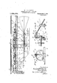
- Fig. 2 is a view in side elevation of the apparatus illustrating the main frame and wing members shown in Fig. 1, together with an aeroplane member located above the same, and a car equipped with a motor suspended below the "same.
- Fig. 3 is a'detail sectiontaken upon line 3-3 of Fig. 1, illustrating the device for giving rising and falling and backward and forward movement to one ofthe wing I plan view of one othe wing, members and members.
- Fig. 1 is a plan view-of the main frame of the machine, the wing members mounted thereon and means on the frame for. actuating'sa-id wing members.
- Fig. 2 is a view in side elevation of the apparatus illustrating the main frame and wing members shown in Fig. 1, together with an aeroplane member located above the same,
- Fig. 4 is a vertical section taken on line 4-4 of Fi 3.
- Fig.5 is a detail associated parts, showing the same at the forward limit of its stroke and in extended position.
- Fig. 6 is a like-plan. view of one of the wing members showing the same at the center of its backward stroke and in a partially folded condition.
- Fig. 7 is a like plan view of one of the wing members I showing the same at the rearward limit of its backward and forward stroke and in its elevation, as seen from its front margin, of a wing member' and its associated parts, taken upon section line 8-8 of Fig. 5.
- Fig. 9 is a view similar to Fig. 8 showing the wing member in its depressed position and partially contracted.
- Fig. 10 is a View like the rearward limit of its backward stroke and in its contracted position.
- Fig. 11 is a detail section taken upon line'll-ll of Fig. 5, showing the guide rods for therear .mar in .of the wingmember.
- Fig. 12 is a detail section taken upon line 12-12 of Fig. 6.
- Fig. 13 is a detail section, taken on line 13-13 of Fig. 5, showing the inclination of the same at the forward limit of its stroke.
- Fig. 14. is a detail section of the wing member taken upon line 14-4 of Fig.;6, showing the inclination of the same at the intermediate point of its backward stroke.
- Fig. 1 5 ⁇ is a detail section of the wing member takenupon line 15-15 of Fig.
- Fig. 16 is a detail section. showing the position of the wing member when at the central part of its forward stroke.
- Fig. 17 is an end view of the apparatus as seen from the front.
- Fig. 18 is a plan view of the suspended car of the new of the joint between two of the frame bars of thewin member illustrated in Fi s. 8, 9 and 101 ig. 20 is a plan view of a form of win member having a rigid frame, together, wit a part of the'frame member which su portsthe same, and parts thereon.
- Fig. 21 1 a sectional view taken on line 21-21 of Fig. 20, showing the frame member and parts thereon, and illustrating the win member. in side elevation.
- Fig. 22 is and parts, thereon shown in Figs. 20 and 21, showing the wing member in end view.
- Fig. 23' is a sectional view taken on line 23-23 of Fig. 20.
- Fig.- 19 is a detail, sectionaL a new in elevation of the-frame member.
- FIG. 8 is a view in frame of the apparatus embraces two lateral, longitudinal frame-members 5, 5, two intermediate, longitudinal frame-members 6, 6 arranged parallel with each other and with the lateral frame members 5, 5,-tran sverse frame-members 7, .7, 7, a forward frame member 8, joining the forward ends of the :lateral frame-members 5,, and a rear frame-member 9 joining the rear end of said lateral frame members 5, 5.
- Said frame members are shownas'made of metal tubes which are rigidly attached to each other at their points of intersection. k
- 10, 10, 10 indicate/wing members, a plurality of which are located on eachside of the machine in the same horizontal plane and which are connected with the lateral longitudinal frame members 5,75 by means.
- the depending, lateral portions of the aeroplane member serve to confine the air from escaping at the'sides of the aeroplane member, so that the latter will act in the nature of a parachute in the descent of the apparatus.
- the car shown is provided with supporting wheels 20, 20 by which the apparatus will be supported when it rests upon the ground.
- Each wing member 10 consists of a light frame, to which is secured a covering of thin flexible material, such as cloth, canvas, rubber or sheet metal.
- the wing member is attached to the outer end of the supporting shaft 25, which is connected by means'of a ball and socket joint 26 with the lateral frame member 5.
- Said ball and socket joint is shown as formed upon the upper end of an arm 50 which is rigidly attached to and rises from the said frame member 5.
- the wing member is attached, at its forward margin, to the outer part or end of the supporting shaft 25, exterior to the ball and socket joint 26, and the outwardly extending end portion of the said supporting shaft constitutes one-of the principal members of the frame of thawing member.
- Said ball and socket joint affords a universal joint-between the said supporting shaft and the mainframe, permitting both rising and falling and backward and forward oscillatory movement in the wing member, and also tilting movement in the wing member, by which the rear margin thereof may be given rising and falling movement relatively to the forward margin of the same.
- the wing members are located in pairs at opposite sides of the main frame, and each pair-of wing members is actuated by means of a horizontal, rotative shaft 27 mounted transversely on the machine frame, in bearings 28, 28 which are attached to the inner longitudinal members 6, 6 of said frame.
- the bearing 28 for each end of the shaft 27 is rigidly secured to the frame member 6 and has thereon a vertically arranged cam-plate 29 provided with a cam groove30 which extends around the shaft 27.
- Said crank arm is provided with longitudinal guides on which is mounted a sliding head 32.
- the crank arm 31 is longitudinally slotted and the sliding head is provided with an arm 33 which extends through the slot in the crank arm and engages the groove 30 in the cam-plate 29.
- the sliding head 32 is connected by a ball and socket joint- 34 with the inner end of a sliding or telescopic section 51 on the inner end of the supporting shaft 25', the socket member of the said joint being carried by the said head and the ball member being formed upon the inner end of said telescopic section 51.
- the inner end of the said supporting shaft- 25 is made hollow or tubular, and the section. 51 is arranged to slide therein.
- the 'wing when elevated and moving forwardly will have a nearly horizontalmovement because of the flattened form of the lower part of the cant ,QI'OOXG and when said Wing member is depressed and is moving backwardly it will move in approximately semi-circular path.
- the wing member in the forward stroke of the wing member the latter will have only a small amount of vertical movemenfiand will act in the nature of an aeroplane member to support the apparatus and during the downstroke of the wing member will move downwardly and rearwardly in a manner adapted to lift the apparatus and impel the same in a forward direction.
- the .wing member is made concave on its lower surface and convex on its upper surfaee so that it will act with greater effect upon the air when movi ng downwardly than when moving upwardly.
- the driving device illustrated for actuating the several shafts 27, 27 27, consists of pulleys 35, 35 afiixed to said shafts, there being two of said pulleys on each shaft excepting those at the forward and rear ends of the main frame, "and driving belts 36, 36 trained over said pulleys.
- the apparatus illustrated is provided with five pairs of wings and five driving shafts therefor, and in this case power for driving the several shafts is applied.
- the driving means illustrated consist of a motor 67 mounted on the car, as shown in Fig. 18 and in dotted lines in Fig. 2, a
- the win member is attached to its supporting sha t 25 adjacent tothe forward margin ofsaid wing member, and as said supporting shaft is adapted to turn or gyrate on its own axis in the ball and socketjoint connecting it with the main frame, the rear margin of the wing member is adapted to swing-or oscillate-up and down about the axis of the said supporting shaft.
- a guide rod 40 is secured transversely to the longitudinal, lateral frame member 5 at the rear of the ball and socket oint 26.
- Said guide-rod 40 is curved concentrically with said ball and socket joint and is made of arched form, with its inner end lower than its outer end.
- the guide-rod 40 extends transversely over the frame member 5 and is connected with the same by means construction illustrated that when the wingmember is at the rearward limit of its movement, and the guide loop 43- is engaged with the lower inner end of the guide-rod, said rear margin of the rin member will be depressed-and when sai wing-member is at the forward limit of its oscillatory movement and the guide loop 43 is engaged with the elevated outer end of said guide rod, said rear margin of the wing-member will be elevated.
- the wing-member illustrated in Figs. 1 to 10 is made extensible and contractible and means are provided for extending or spreading the same during its forward movement and contracting or folding it during its rearward stroke, so that said wing member will be in extended position when making its downward or lifting stroke and in its contracted condition when making its upward stroke, the devices for this purpose being constructed as follows:
- the frame of the wing member embraces jointed or flexibly connected frame bars, the
- the inner portion of the wing-member, which is attached to and directly supported by the outer part of the shaft 25 is provided with a rigid frame over which the inner portion of the cloth covering is stretched, as clearly seen in dotted lines in Fig. 5.
- an actuating bar 47 is pivoted to the machine frame at a point horizontally distant from and at the rear of the ball and socket joint 26, and at its outer end is pivoted to the said frame member 45, near the outer endof the same.
- the said bar 47 is located in the same plane with, and passes through a longitudinal slot in, the said shaft 25.
- the actuating bar 47 thus arranged serves to extend the intermediate frame-bar 45 or swing the same outwardly more nearly into alinement with the shaft 25, when the wing member is swung to its forward position as shown in Fig. In the back stroke of the wing-member, however, said bar 47 flexes the frame member 45 rearwardly as seen in Figs. 6 and 7.
- the bar 47 is extended at its outer end outwardly from the pivot connecting the same with the frame bar 45, and to the extremity of said bar 47 is pivotally connected one end of a link 48.
- the opposite end 0ff ⁇ 'hlCl1 link is connected with an inwardly projecting lug on the said terminal frame-member 46.
- paid outer end ofthe frame bar 47 extends in a direction substantially transverse to the frame-member 45, so that when the said bar 47 is swung or turned on its pivot connecting it with said bar, as the latter swings rearwardly, the link 48 will flex the terminal frame-member 46 rearwardly as seen in Figs. 6 and 7.
- the frame bar 45 has at its outer end an upright rigidly attached hollow or tubular hinge member 80 through which passes an upright pivot bolt 81, and the frame bar 46 has at its inner end a rigidly attached upright arm 82. provided with upper and lower lugs 83 and 84 which are engaged by the upper and lower ends of said pivot bolt.
- the hinged connection between the outer end of the shaft 25 and the intermediate frame bar 45 will be similarly constructed, as seen in Figs. 8, 9 and 10.
- a rudder 55 is mounted on the rear end of the car 16 for steering the apparatus. As illustrated, said rudder is provided with both vertical and horizontal wings and is made of tapered form, being wider at 'its rear than-at its forwardend. Said rudder is connected by a universal joint with the rear end of the car, so that'it maybe raised or lowered or moved laterally for giving either the rising or falling ⁇ or lateral movement to the apparatus.
- a horizontal rudder. 56 adapted to give rising and falling movement to the said forward end of the apparatus.
- transverse frame member 8 is extended at its ends outside of the main, longitudinal frame. members 5, 5 and is extended up wardly to form two supporting standards 57, 57 (Fig. 17
- the said rudder 56 consists of a flat rectangular frame over which flexible material is stretched and secured.
- the said rudder is pivoted at its ends to the upper ends of the standards 57 57 so that it will swing on an axis midway between its forward and rear ed es
- cables 58 and 59 are attached to the forward and rear margin of the rudder and are led downwardly to guide pulleys 60 and 61 on the forward end of thecar, and
- propellers .65, 65 mounted on the car 16 at the rear end thereof aretwo propellers .65, 65 arranged at opposite sides of the center line of the apparatus and in the same horizontal plane.
- Said propellers serve to aid'in the propulsion of the apparatus but are designed mainly
- Said propellers are nally arranged nearly horizontal shafts 66, 66 which are mounted in suitable bearings on the car, and are adapted to slide endwise in said bearings.
- the motor 67 by which the wings are given movement, as hereinbefore described, is provided with a horizontal driving shaft- 68 extending transversely of the car.
- a countershaft 69 located forward of the motor, is driven from the shaft 68 by a chain-belt 70 and is provided with a sprocket wheel 71 over which the driving belt 38 is trained.
- On the ends of the shaft 68 are secured bevel gear wheels 72, 72.
- the forward ends of the -propeller shafts 66,66 are arranged transversely of the ends of said shaft 68 outside ofand parallel with the bevel gear wheels 72, 72.
- On each of said propeller shafts are secured two bevel gear-pinions 73, 74 arranged on the said propeller'shaft at a distance apart somewhat greater than the diameter of said gear wheel 72.
- One or the other of said gear-pinions 73 and 74 may be brought into intermeshing engagement with the gear wheel 72 by giving endwise movement to the propeller shaft.
- Two operating levers 75, 75 are mounted on the car and are engaged with the propeller shafts in a manner to give endwise movement to the same.
- either of the geanpinions 73 and 74 on either shaft may be brought into engagement with one of the gear wheels 72, 72, or both gear-pinions may be. disengaged from said gear wheels. It follows that by movement of said operat ,ing levers both.
- propellers may be driven in a direction to propel the apparatus, either propeller may be driven forward or backward while the other propeller is out of use, or one propeller maybe driven forward and the other backward.
- both propellers When both propellers are driven forwardly, or in a direction to give forward movement to the apparatus, the propellers will aid the wings in the propulsion of the apparatus, as may be necessary in navigating against high winds or in emergencies.
- Both propellers may be turned backward to quickly arrest the forward movement of the apparatus, as when making a landing
- the apparatus By turning one propeller either backward or forward, the apparatus may be turned to the right or left in steering more promptly than when the steering rudder is relied upon alone for this purpose.
- the two propellers are r0 tated at the same time a quick turn either to the right or left may be made for emergencies.
- the apparatus illustrated is provided with closed, longitudinally extending tubes 76, 76 secured to the frame of the aeroplane member 15 at the side margins of the latter, and with like closed tubes 77, 77 secured to the sides of the car 16. Said tubes insure flotation of the apparatus in case the same should descend upon the they may constitute reservoirs to contain a supply of gas under compression when gaseous fuel is used in the motor.
- wing member is not eX- pansible and contractible, but its frame consists of rigidly connectedmembers, preferably having the form of a marginal frame member 78 and curved, radiating ribs 79,
- Said tubes may be filled with air or.
- the wing members shown in said Figs. 20 to 23 operate in the same manner as those illustrated in the other figures of the drawings, and, if found desirable or preferable, wing members of both the kinds illustrated may be employed in the-same apparatus.
- the two kinds may be arranged in alternation with each other at each side of the apparatus, or in any other suitable relative position or arrangement.
- an apparatus for aerial navigation the combination with a main frame, of a wing-member provided with a frame, an operative shaft to which said wing-member frame is attached, said operating shaft being connected with the frame by a ball and socket joint, means acting on said shaft giving rising and falling and forward and backward oscillatory movement to the wingmember, and a guide on the main frame engaging said wing-member frame at a point rearwardly of the said shaft and acting through the oscillatory movement of the wing-member to give rising and falling movement to the rear, relatively to the forward, edge of said wing-member.
- a wing-member having a frame which is connected with said main frame by a universal joint affording turning movement in the wing in a manner permitting rising and falling movement of the rear margin relatively to the forward margin of the wingmember, means giving rising and falling and backward and forward oscillatory movement to said wing-member, and a transversely arranged guide rod on the main frame, curved concentrically with said universal joint, and having its inner end lower than its outer end, said wing-member having a guide loop at its rear portion adapted to slide on said guide-rod.
- an apparatus for aerial navigation the combination with a main frame, of a wing member connected by a universal joint witln said main frame, means giving rising and falling and backward and forward movement to said wing-member, said wingmember having a frame embrzicing three jointed frame bars, adapted to be flexed upon each other in the plane of the wings member, an actuating bar pivoted to the main frame at a point horizontally distant from said universal joint and to the intermediate jointed frame-bar, between the ends of the latter, and a second actuating bar pivoted to the first named actuating bar and to the outermost of said jointed frame bars.
- a wing-men'iber having rising and falling and backward and forward oscillatory motion, jointed frame bars for said wing-member, and means forflexing said frame bars on each other, operated by the backward and forward oscillatory motion of the wingmember, the joints between said frame bars being formed by means of vertically elongated hinge-members rigidly attached to the adjacent ends of said frame bars and pivot.- ally' connected with each other.
- a horizontally extending main frame wingmembers supported on the sides of the main frame and having rising and falling and backward and forward oscillatory motion, a horizontally extending aeroplane member rigidly connected with the main frame.
- a car suspended from the main frame, a horizontal rudder mounted on the main frame and adapted to turn on a horizontal transverse pivotal axislocated between its forward and rear margins, and ropes connected with said rudder at points forward and at the rear ofits pivotal axis, and a Windlass on the car for operating said ropes.
- a'horizontally extending -main frame Wing members supported on the sides of themain frame and having rising and falling and backward and forward oscillatory motion, a car suspended beneath said main frame, a rudder on the rear end of the car having vertical and horizontal surfaces and adapted for both vertical and horizontal movement, and a horizontal rudder mounted on the forward end of the main frame.
- An apparatus for aerial navigation embracing a main frame, wing members supported on the sides of the main frame and having rising and falling and backward the presence of two witnesseses, this 21st day and forward oscillatory motion, a'horizonof June A. D. 1909. tally extending aeroplane member rigidly RANDOLPH R. RAWLE. attached to sald main frame and closed cyl- 4 inders attached to the side inargins of, said JOHN RAWLE' aeroplane member.
Landscapes
- Engineering & Computer Science (AREA)
- Aviation & Aerospace Engineering (AREA)
- Toys (AREA)
Description
-R. R. & J. RA WLE, APPARATUS FOR AERIAL NAVIGATION.
- APPLIOATIONIILED Jun: 24,1909.
1,025,306. Patented May 7, 1912.
6 SHEETB-SHEHT 1.
R. R. & J. RAWLE. APPARATUS FOR AERIAL NAVIGATION.
APPLICATION FILED JUNBM, 1909.
Patented May 7, .1912.
' it-Vizior s:
. 07z1z7iaude |Jil R. R. & J. RAWLE. APPARATUS roa AERIAL NAVIGATION.
APPLICATION FILED JUNE 24, 1909 I Patented May 7, 1912.
6 sums-81mm 3.
at, @4 QM R. R. & J. RAWLEL- APPARATUS FOB. AERIAL NAVIGATION.
' APPLICATION FILED JUNE 24, 1909, 1 ,O25,306.
R. R. & J. RAWLE.
Patented May 7, 1912.
6 SHEETS-SHEET 5.
k, a A A Maia/1s.- Banded 2Z2 EFawie/ v F APPARATUS FOR AERIAL NAVIGATION.
APPLICATION FILED JUNE 24, 1909- 1,025,306.
R. R. & J. RAWLEL.
APPARATUS FOR AERIAL NAVIGATION.
APPLIOATION FILED 111111124, 1909.
Patented May 7, 1912.
6 SHEETS-"SHEET 6. I
UNITED, srAa ns PATENT OFFICE.
RANDOLPH It. RAWLE AND JOHN RAWLE, OF CH ICAGO, ILLINOIS.
APPARATUS FOR AERIAL NAVIGATION.
' Specification of Letters Patent.
I Patented May '7 1912 Application filed. June 1-24, 1908. Serial No. 503,985.
RAWLE and Joint BAWLE, citizens of the United States, and residents of Chicago, in the county of Cook and State of Illinois,
have invented certain new and useful Improvements in Apparatus for Aerial Navigation; and we do hereby declare that the following is a full, clear, and exact description thereof, reference being had to the accompanying drawings, and to the letters of reference marked thereon, which I form a part of this specification. 1
This invention relates to an apparatus for aerial navigation of that class embracing a plurality of wing members which have both rising and falling and backward and forward movement in a manner to both lift the apparatus and propel the same" forwardly. V
The invention consists in the matters hereinafter described and pointed out in the appended claims.
The invention may be more readily understood by reference to the accompanying drawings, in which- Figure 1 is a plan view-of the main frame of the machine, the wing members mounted thereon and means on the frame for. actuating'sa-id wing members. Fig. 2 is a view in side elevation of the apparatus illustrating the main frame and wing members shown in Fig. 1, together with an aeroplane member located above the same, and a car equipped with a motor suspended below the "same. Fig. 3 is a'detail sectiontaken upon line 3-3 of Fig. 1, illustrating the device for giving rising and falling and backward and forward movement to one ofthe wing I plan view of one othe wing, members and members. Fig. 4 is a vertical section taken on line 4-4 of Fi 3. Fig.5 is a detail associated parts, showing the same at the forward limit of its stroke and in extended position. Fig. 6 is a like-plan. view of one of the wing members showing the same at the center of its backward stroke and in a partially folded condition. Fig. 7 is a like plan view of one of the wing members I showing the same at the rearward limit of its backward and forward stroke and in its elevation, as seen from its front margin, of a wing member' and its associated parts, taken upon section line 8-8 of Fig. 5. Fig. 9 is a view similar to Fig. 8 showing the wing member in its depressed position and partially contracted. Fig. 10 is a View like the rearward limit of its backward stroke and in its contracted position. Fig. 11 is a detail section taken upon line'll-ll of Fig. 5, showing the guide rods for therear .mar in .of the wingmember. Fig. 12 is a detail section taken upon line 12-12 of Fig. 6. Fig. 13 is a detail section, taken on line 13-13 of Fig. 5, showing the inclination of the same at the forward limit of its stroke. Fig. 14. is a detail section of the wing member taken upon line 14-4 of Fig.;6, showing the inclination of the same at the intermediate point of its backward stroke. Fig. 1 5\is a detail section of the wing member takenupon line 15-15 of Fig. 7, showing the position of the same at the rearward limit of its stroke. Fig. 16 is a detail section. showing the position of the wing member when at the central part of its forward stroke. Fig. 17 is an end view of the apparatus as seen from the front. Fig. 18 is a plan view of the suspended car of the new of the joint between two of the frame bars of thewin member illustrated in Fi s. 8, 9 and 101 ig. 20 is a plan view of a form of win member having a rigid frame, together, wit a part of the'frame member which su portsthe same, and parts thereon. Fig. 21 1s a sectional view taken on line 21-21 of Fig. 20, showing the frame member and parts thereon, and illustrating the win member. in side elevation. Fig. 22 is and parts, thereon shown in Figs. 20 and 21, showing the wing member in end view. Fig. 23' is a sectional view taken on line 23-23 of Fig. 20.
As shown in said drawings, the main Figs 8 and 9 showing the wing member in apparatus. Fig.- 19 is a detail, sectionaL a new in elevation of the-frame member.
retracted condition. -Fig. 8 is a view in frame of the apparatus embraces two lateral, longitudinal frame- members 5, 5, two intermediate, longitudinal frame- members 6, 6 arranged parallel with each other and with the lateral frame members 5, 5,-tran sverse frame-members 7, .7, 7, a forward frame member 8, joining the forward ends of the :lateral frame-members 5,, and a rear frame-member 9 joining the rear end of said lateral frame members 5, 5. Said frame members are shownas'made of metal tubes which are rigidly attached to each other at their points of intersection. k
10, 10, 10 indicate/wing members, a plurality of which are located on eachside of the machine in the same horizontal plane and which are connected with the lateral longitudinal frame members 5,75 by means.
, 16 is supported centrally below the said main frame. Said car is suspended from the main frame by means of rods 17, 17, 17 rising from the car in radial relation to each other, and, connected with the marginal frame members of the main frame. Other rods 18, 18, preferably arranged in line with the rods 17, 17, 17, extend upwardly from the main frame to the margins of the aeroplane member 15, and serve to rigidly connect said member with the main frame. As clearly seen in Fig, 17, said aeroplane member 15 is extended laterally outside of the wing members 10, 10 and the side margins are deflected downwardly and terminate below the level of the wing members. The lower edges-of said aeroplane members are connected with the car 16 by oblique wires or cables19, 19. The depending, lateral portions of the aeroplane member, arranged as described, serve to confine the air from escaping at the'sides of the aeroplane member, so that the latter will act in the nature of a parachute in the descent of the apparatus. The car shown is provided with supporting wheels 20, 20 by which the apparatus will be supported when it rests upon the ground. Each wing member 10 consists of a light frame, to which is secured a covering of thin flexible material, such as cloth, canvas, rubber or sheet metal. The wing member is attached to the outer end of the supporting shaft 25, which is connected by means'of a ball and socket joint 26 with the lateral frame member 5. Said ball and socket joint is shown as formed upon the upper end of an arm 50 which is rigidly attached to and rises from the said frame member 5. The wing member is attached, at its forward margin, to the outer part or end of the supporting shaft 25, exterior to the ball and socket joint 26, and the outwardly extending end portion of the said supporting shaft constitutes one-of the principal members of the frame of thawing member. Said ball and socket joint affords a universal joint-between the said supporting shaft and the mainframe, permitting both rising and falling and backward and forward oscillatory movement in the wing member, and also tilting movement in the wing member, by which the rear margin thereof may be given rising and falling movement relatively to the forward margin of the same. The wing members are located in pairs at opposite sides of the main frame, and each pair-of wing members is actuated by means of a horizontal, rotative shaft 27 mounted transversely on the machine frame, in bearings 28, 28 which are attached to the inner longitudinal members 6, 6 of said frame.-
As clearly seen in Figs. 3 and 4, the bearing 28 for each end of the shaft 27 is rigidly secured to the frame member 6 and has thereon a vertically arranged cam-plate 29 provided with a cam groove30 which extends around the shaft 27. vTo the end of the shaft 27, outside of the canrplate 29, is secured a crank arm 31. Said crank arm is provided with longitudinal guides on which is mounted a sliding head 32. The crank arm 31 is longitudinally slotted and the sliding head is provided with an arm 33 which extends through the slot in the crank arm and engages the groove 30 in the cam-plate 29. The sliding head 32 is connected by a ball and socket joint- 34 with the inner end of a sliding or telescopic section 51 on the inner end of the supporting shaft 25', the socket member of the said joint being carried by the said head and the ball member being formed upon the inner end of said telescopic section 51. The inner end of the said supporting shaft- 25 is made hollow or tubular, and the section. 51 is arranged to slide therein. By reason of the sliding ortelescopic joint between the said supporting shaft 25 and the inner section 51 thereof, the latter is adapted to follow a path corresponding with the shape of the cam groove 30, parts of which are located at different distances from the ball and socket joint'34. \Vhen the shaft 27 is rotated the crank-arm 31 will give rotative movement to the head 32, and the inner end of the arm 33 on the head will thereby by moved along the cam-grooves 30 as the head 32 iscarried around the axis of the shaft 27, thereby giving rising and falling and also backward and forward movement to the wing member, which is carried upon five.
the outer end of said supporting shaft 25.
The engagement of the stud 33 with the eam-groove 30 produces a radial movement of thehead 32 on the crank-arm, so that centric with the shaft 27 while its lower part is much nearer the axis of said shaft than its upper part and is nearly straight. Inasmuch as the wing member is elevated when the. inner end of the shaft 25 is opposite the lower part of said cam groove, and is depressed when the inner end of said shaft is opposite the upper partof the. cam groove, the path of movement of the wing when elevated will be determined by the shape of the lower part of the cam-groove, and vice versa. In other words, the direction of movement of the wing member in any part of its loop-shaped path will be determined by the shape of the corresponding opposite portion of the cam groove. In the construction illustrated, therefore, the 'wing when elevated and moving forwardly will have a nearly horizontalmovement because of the flattened form of the lower part of the cant ,QI'OOXG and when said Wing member is depressed and is moving backwardly it will move in approximately semi-circular path. It follows that, in the forward stroke of the wing member the latter will have only a small amount of vertical movemenfiand will act in the nature of an aeroplane member to support the apparatus and during the downstroke of the wing member will move downwardly and rearwardly in a manner adapted to lift the apparatus and impel the same in a forward direction. The .wing member is made concave on its lower surface and convex on its upper surfaee so that it will act with greater effect upon the air when movi ng downwardly than when moving upwardly. v
The driving device illustrated for actuating the several shafts 27, 27 27, consists of pulleys 35, 35 afiixed to said shafts, there being two of said pulleys on each shaft excepting those at the forward and rear ends of the main frame, "and driving belts 36, 36 trained over said pulleys. The apparatus illustrated is provided with five pairs of wings and five driving shafts therefor, and in this case power for driving the several shafts is applied. to the central one of the The driving means illustrated consist of a motor 67 mounted on the car, as shown in Fig. 18 and in dotted lines in Fig. 2, a
driving pulley 37 aflixed to the central shaft 27, and a chain belt 38 by means of which motion is transmitted from the motor to said pulley 37. The several pulleys 35, and
37 are shown as having the form of sprocket -wheels and the driving belts 36 as consisting of chain belts.
Devices are provided for giving rising and falling movement to the rear margins'of the wing-member relatively to the forward margin thereof as follows: As hereinbefore stated, the win member is attached to its supporting sha t 25 adjacent tothe forward margin ofsaid wing member, and as said supporting shaft is adapted to turn or gyrate on its own axis in the ball and socketjoint connecting it with the main frame, the rear margin of the wing member is adapted to swing-or oscillate-up and down about the axis of the said supporting shaft. F or imparting rising and falling movementto the rear margins of the wing member a guide rod 40 is secured transversely to the longitudinal, lateral frame member 5 at the rear of the ball and socket oint 26. Said guide-rod 40 is curved concentrically with said ball and socket joint and is made of arched form, with its inner end lower than its outer end. As preferably constructed, the guide-rod 40 extends transversely over the frame member 5 and is connected with the same by means construction illustrated that when the wingmember is at the rearward limit of its movement, and the guide loop 43- is engaged with the lower inner end of the guide-rod, said rear margin of the rin member will be depressed-and when sai wing-member is at the forward limit of its oscillatory movement and the guide loop 43 is engaged with the elevated outer end of said guide rod, said rear margin of the wing-member will be elevated. These parts are so arranged moreover, that when the wing-member is at the forward limit of its movement, as seen in Figs. 5, 8 and 13, the wing will have an intermediate rearward and upward inclination from its forward edge, when the wing-member is in the intermediate part of its baele ward stroke, as seen in Figs. 6, 9 and 14, the wingmember will have a maximum upward and rearward inclination from its forward edge,'whcn said wing-member is at the rearward limit of its movement, the wing-memher will be substantially horizontal, as seen in Figs. 7, 10 and 15, and when the wing.
member is in the intermediate part of its forward stroke, as seen in said Fig. 6 and in' tially no resistance to the forward movement of the apparatus and act as an aeroplane member to aid in supporting the apparatus.
The wing-member illustrated in Figs. 1 to 10 is made extensible and contractible and means are provided for extending or spreading the same during its forward movement and contracting or folding it during its rearward stroke, so that said wing member will be in extended position when making its downward or lifting stroke and in its contracted condition when making its upward stroke, the devices for this purpose being constructed as follows: The frame of the wing member embraces jointed or flexibly connected frame bars, the
, innermost one of which is formed by the outer part of the supporting shaft 25 and the outer ones of which consist of an intermediate frame-bar 45 pivoted to the outer end of the shaft 25, and a terminal frame bar 46, pivoted to, the outer end of the frame bar 45. The pivotal connections between said frame bars are so constructed that the same will be flexed upon each other in the plane of the wing-member, in such manner that the two outermost frame bars may be flexed or swung or folded rearwardly with the effect of contracting the wing-member, the cloth covering of which is adapted tobc stretched tightly when the wing-member is extended, as shown in Fig. ,5, and to be loosely folded when the wing-member'is partially or fully contracted as shown in Figs. 6 and 7. Preferably, the inner portion of the wing-member, which is attached to and directly supported by the outer part of the shaft 25 is provided with a rigid frame over which the inner portion of the cloth covering is stretched, as clearly seen in dotted lines in Fig. 5. For the purpose of flexing the. intermediate frame member 45 relatively to the supporting shaft 25, an actuating bar 47 is pivoted to the machine frame at a point horizontally distant from and at the rear of the ball and socket joint 26, and at its outer end is pivoted to the said frame member 45, near the outer endof the same. As illustrated, the said bar 47 is located in the same plane with, and passes through a longitudinal slot in, the said shaft 25. The actuating bar 47 thus arranged serves to extend the intermediate frame-bar 45 or swing the same outwardly more nearly into alinement with the shaft 25, when the wing member is swung to its forward position as shown in Fig. In the back stroke of the wing-member, however, said bar 47 flexes the frame member 45 rearwardly as seen in Figs. 6 and 7. For giving like flexing movement to the terminal frame-member 46 on the intermediate frame-member 45, the bar 47 is extended at its outer end outwardly from the pivot connecting the same with the frame bar 45, and to the extremity of said bar 47 is pivotally connected one end of a link 48. the opposite end 0ff\\'hlCl1 link is connected with an inwardly projecting lug on the said terminal frame-member 46. paid outer end ofthe frame bar 47 extends in a direction substantially transverse to the frame-member 45, so that when the said bar 47 is swung or turned on its pivot connecting it with said bar, as the latter swings rearwardly, the link 48 will flex the terminal frame-member 46 rearwardly as seen in Figs. 6 and 7.
It follows from the construction described that when the wing member is at. the forward or advance limit of its stroke the frame- members 45 and 46 will be fully extended and when said wing mcnibcr is in the rearward limit of its movement said framemembers will be flexed to a maximum extent relatively to each other and the wing menibers will be fully contracted. Inasmuch as the wing member will be in an expanded condition when advanced and making its downward stroke, it will be seen that at this time it will present its broadest expanse for action against the air, and that when said wing member is at the rearward limit of its stroke and is rising it will be contracted and will present a minimum area or surface 'of the wing member may be held rigidly in the-same plane with each other and the shaft 25, notwithstanding the upward pressure of the air on the outer end of the wing member, a special construction is provided on the joints between said frame bars. as clearly shown in Fig. 19. As illustrated in said Fig. 19, the frame bar 45 has at its outer end an upright rigidly attached hollow or tubular hinge member 80 through which passes an upright pivot bolt 81, and the frame bar 46 has at its inner end a rigidly attached upright arm 82. provided with upper and lower lugs 83 and 84 which are engaged by the upper and lower ends of said pivot bolt. The hinged connection between the outer end of the shaft 25 and the intermediate frame bar 45 will be similarly constructed, as seen in Figs. 8, 9 and 10.
A rudder 55 is mounted on the rear end of the car 16 for steering the apparatus. As illustrated, said rudder is provided with both vertical and horizontal wings and is made of tapered form, being wider at 'its rear than-at its forwardend. Said rudder is connected by a universal joint with the rear end of the car, so that'it maybe raised or lowered or moved laterally for giving either the rising or falling\or lateral movement to the apparatus.
At the forward end of the apparatus, beneath the aeroplane member 15, is located a horizontal rudder. 56 adapted to give rising and falling movement to the said forward end of the apparatus. To afiord support for said horizontal rudder the front, transverse frame member 8 is extended at its ends outside of the main, longitudinal frame. members 5, 5 and is extended up wardly to form two supporting standards 57, 57 (Fig. 17 The said rudder 56 consists of a flat rectangular frame over which flexible material is stretched and secured. The said rudder is pivoted at its ends to the upper ends of the standards 57 57 so that it will swing on an axis midway between its forward and rear ed es For movin or shifting the rudder 56 and holding the same in position, cables 58 and 59 are attached to the forward and rear margin of the rudder and are led downwardly to guide pulleys 60 and 61 on the forward end of thecar, and
i thence over other guide pulleys to a handas an aid in steering.
mounted on the rear ends of the longitudv operated windlass 62, around which they are wound in opposite directions, so that, by the turning of said Windlass, the forward and rear edges of said rudder may be correspondingly raised or lowered.
Mounted on the car 16 at the rear end thereof aretwo propellers .65, 65 arranged at opposite sides of the center line of the apparatus and in the same horizontal plane. Said propellers serve to aid'in the propulsion of the apparatus but are designed mainly Said propellers are nally arranged nearly horizontal shafts 66, 66 which are mounted in suitable bearings on the car, and are adapted to slide endwise in said bearings. The motor 67 by which the wings are given movement, as hereinbefore described, is provided with a horizontal driving shaft- 68 extending transversely of the car. A countershaft 69, located forward of the motor, is driven from the shaft 68 by a chain-belt 70 and is provided with a sprocket wheel 71 over which the driving belt 38 is trained. On the ends of the shaft 68 are secured bevel gear wheels 72, 72. The forward ends of the -propeller shafts 66,66 are arranged transversely of the ends of said shaft 68 outside ofand parallel with the bevel gear wheels 72, 72. On each of said propeller shafts are secured two bevel gear- pinions 73, 74 arranged on the said propeller'shaft at a distance apart somewhat greater than the diameter of said gear wheel 72. One or the other of said gear- pinions 73 and 74 may be brought into intermeshing engagement with the gear wheel 72 by giving endwise movement to the propeller shaft. Two operating levers 75, 75 are mounted on the car and are engaged with the propeller shafts in a manner to give endwise movement to the same. By shifting said operating levers either of the geanpinions 73 and 74 on either shaft may be brought into engagement with one of the gear wheels 72, 72, or both gear-pinions may be. disengaged from said gear wheels. It follows that by movement of said operat ,ing levers both. propellers may be driven in a direction to propel the apparatus, either propeller may be driven forward or backward while the other propeller is out of use, or one propeller maybe driven forward and the other backward. When both propellers are driven forwardly, or in a direction to give forward movement to the apparatus, the propellers will aid the wings in the propulsion of the apparatus, as may be necessary in navigating against high winds or in emergencies. Both propellers may be turned backward to quickly arrest the forward movement of the apparatus, as when making a landing By turning one propeller either backward or forward, the apparatus may be turned to the right or left in steering more promptly than when the steering rudder is relied upon alone for this purpose. When the two propellers are r0 tated at the same time a quick turn either to the right or left may be made for emergencies. The apparatus illustrated is provided with closed, longitudinally extending tubes 76, 76 secured to the frame of the aeroplane member 15 at the side margins of the latter, and with like closed tubes 77, 77 secured to the sides of the car 16. Said tubes insure flotation of the apparatus in case the same should descend upon the they may constitute reservoirs to contain a supply of gas under compression when gaseous fuel is used in the motor.
In Figs. 20, 21, 22 and 23 is 'shown a form of construction in thawing members which may be used in place of that shown in the figures hereinbefore described. In this instance, the wing member is not eX- pansible and contractible, but its frame consists of rigidly connectedmembers, preferably having the form of a marginal frame member 78 and curved, radiating ribs 79,
79 secured at their inner ends to the shaft water. Said tubes may be filled with air or.
25, near the frame member 5, and at their outer ends to the marginal frame member 78. So far as the tilting movement in the wing members by which their rear margins are given a rising and falling motion relatively to their forward margins, the wing members shown in said Figs. 20 to 23 operate in the same manner as those illustrated in the other figures of the drawings, and, if found desirable or preferable, wing members of both the kinds illustrated may be employed in the-same apparatus. When such non-expansible wing members are'employed in connection with the expansible wing members shown in Figs. 5, 6 and 7, the two kinds may be arranged in alternation with each other at each side of the apparatus, or in any other suitable relative position or arrangement.
It is to be understood that we have shown in the-accompanying drawings one practical embodiment of an apparatus embodying our invention and that we do not desire to be limited to the specific features of construction illustrated in the said drawings, except so far asthe same may be set forth in the appended claims as constituting parts of features of our invention.
\Ve claim as our invention 1. In an apparatus for aerial navigation, the combination with the frame of the apparatus, of a wing member connected with the frame by means affording universal swinging movement of the wing member relatively to the frame and also rotat-ive movement of said wing member on its longitudinal axis, and actuating means on the frame operating on the wing member to give to the latter rising and falling and backward and forward oscillatory movement, to-
gether with a simultaneous rotative or tilt ing movement, affording rising and falling motion of the rear, relatively to the forward, part of the said wing member at each stroke of the same.
2. Inan apparatus for aerial navigation, the combination with the frame of the apparatus, of a wing-member connected with the frame by means affording universal movement of the wing-member on the frame, actuating means on the frame giving rising and falling and also backward and forward oscillatory movement to said wing-member, and a guide on the frame engaged with the rear part of the wing-member and acting to give rising and falling n'lovement to said rear part, relatively to the forward part of the wing-member, in the oscillatory movement of the latter.
3. In an apparatus for aerial navigation, a wing member-provided with a frame embracing frame bars pivotally connected with each other at their ends to permit the wing to be longitudinally expanded and contracted by the flexing of the frame bars oneach other, actuatingmeans acting on the frame as a whole to give rising and falling and forward and rearward oscillatory motion thereto, and actuating means operating through the oscillatory movement of the frame as a whole and acting on the frame bars to flex the same on each other and to thereby longitudinally expand and contract the said wing member automatically during the oscillatory movement of the same.
41. In an apparatus for aerial navigation, the combination with a main frame, of a wing-member having a frame which is com nected with the main frame by a universal joint, means acting on the wing-member frame to give rising and falling and backward and forward oscillatory motion thereto, and a guide on the main frame engaging the rear part of the wing-member frame and acting in connection with the oscillatory motion of said wing-member to give rising and falling movement to the rear, relatively to the forward, margin of said wing-member.
5. In an apparatus for aerial navigation, the combination with a main frame, of a wing-member provided with a frame, an operative shaft to which said wing-member frame is attached, said operating shaft being connected with the frame by a ball and socket joint, means acting on said shaft giving rising and falling and forward and backward oscillatory movement to the wingmember, and a guide on the main frame engaging said wing-member frame at a point rearwardly of the said shaft and acting through the oscillatory movement of the wing-member to give rising and falling movement to the rear, relatively to the forward, edge of said wing-member.
6. In an apparatus for aerial navigation, the combination with a main frame, of a wing-member having a frame which is connected with said main frame by a universal joint affording turning movement in the wing in a manner permitting rising and falling movement of the rear margin relatively to the forward margin of the wingmember, means giving rising and falling and backward and forward oscillatory movement to said wing-member, and a transversely arranged guide rod on the main frame, curved concentrically with said universal joint, and having its inner end lower than its outer end, said wing-member having a guide loop at its rear portion adapted to slide on said guide-rod.
7,. In an apparatus for aerial navigation, the combination with a main frame, of a wing-member provided with a frame, an actuating shaft to which said wing-member frame is attached, a universal joint connect ing the said shaft with the main frame, a rotative shaft provided with a crank arm which acts on the said shaft to give rising and falling and backward and forward s cillatory movement to the wing-member, and a fixed cam on the machine frame, noting 011 said shaft to give to the wing-member movement in a path corresponding with the form of said cam.
8. In an apparatus for aerial navigation, the combination with a main frame, of a wing-member, an actuating shaft to which said wing-member is attached, auniversal joint connecting the said shaft with the main frame, a rotative shaft provided with a crank arm, a slide on the crank arm connected with the said wing-member shaft by a universal joint, and a cam on-t-he main frame acting on the said slide to give inward and outward movement of the same on the crank arm.
9. In an apparatus for aerial navigation, the combination with a main frame, of a wing-member connected by a universal joint with the main frame, means for giving rising and falling and backward and forward movement to the wing-member, said wingmember having a frame which includes two jointed frame-bars adapted to be flexed upon each other in the plane of the wing-member, and an actuating bar pivoted to the main frame, at a point horizontally distant from the said universal joint, and to the outermost of said jointed frame bars, said actuating bar being adapted to flex the said frame bars in the backward and forward movement of the wing-member.
10. In an apparatus for aerial navigation, the combination with a main frame, of a wing member connected by a universal joint witln said main frame, means giving rising and falling and backward and forward movement to said wing-member, said wingmember having a frame embrzicing three jointed frame bars, adapted to be flexed upon each other in the plane of the wings member, an actuating bar pivoted to the main frame at a point horizontally distant from said universal joint and to the intermediate jointed frame-bar, between the ends of the latter, and a second actuating bar pivoted to the first named actuating bar and to the outermost of said jointed frame bars.
11. In an apparatus for aerial navigation, the combination with a main frame, of a wingmember, a supporting shaft for said wing-member which is connected with the main frame by a universal joint, means acting on the inner end of said supporting shaft, giving rising and falling and backward and forward movement to said wingmember, said wmg-member having a frame consisting of three jointed frame bars, the
innermost one of which is formed by the prolonged outer end of said supporting shaft, and which are adapted to be flexed on each other-in the plane of the wingmember, and two actuating bars, one of which is pivoted tothe machine frame at a point horizontally distant from said universal joint, and is also pivoted to the intermediate jointed frame bar, and the other of which is pivoted to the outer end of said first named actuating bar and to the outermost of said frame bars.
12. In an apparatus for aerial navigation, a wing-men'iber having rising and falling and backward and forward oscillatory motion, jointed frame bars for said wing-member, and means forflexing said frame bars on each other, operated by the backward and forward oscillatory motion of the wingmember, the joints between said frame bars being formed by means of vertically elongated hinge-members rigidly attached to the adjacent ends of said frame bars and pivot.- ally' connected with each other.
13. In an apparatus for aerial navigation, the combination with a main frame having longitudinal, lateral frame members, of a plurality of wing-members severally pro vided with supporting shafts which are connected with the said tubular frame members by ball-and-socket joints, means on the main frame acting on the inner ends of the supporting shafts to give oscillatory rising and falling and backward and forward motion to said wing-members, and transversely extending, curved guide rods secured to said lateral frame members, and guide loops attached to the rear parts of the wingmembers and having sliding engagement with said guide rods.
14. In an apparatus for aerialnavigation, a horizontally extending main frame, wingmembers supported on the sides of the main frame and having rising and falling and backward and forward oscillatory motion, a horizontally extending aeroplane member rigidly connected with the main frame. above the level of the said wing members, a car suspended from the main frame, a horizontal rudder mounted on the main frame and adapted to turn on a horizontal transverse pivotal axislocated between its forward and rear margins, and ropes connected with said rudder at points forward and at the rear ofits pivotal axis, and a Windlass on the car for operating said ropes.
15. In an apparatus for aerial navigation, a'horizontally extending -main frame, Wing members supported on the sides of themain frame and having rising and falling and backward and forward oscillatory motion, a car suspended beneath said main frame, a rudder on the rear end of the car having vertical and horizontal surfaces and adapted for both vertical and horizontal movement, and a horizontal rudder mounted on the forward end of the main frame.
16. An apparatus for aerial navigation embracing a main frame, wing members supported on the sides of the main frame and having rising and falling and backward the presence of two Witnesses, this 21st day and forward oscillatory motion, a'horizonof June A. D. 1909. tally extending aeroplane member rigidly RANDOLPH R. RAWLE. attached to sald main frame and closed cyl- 4 inders attached to the side inargins of, said JOHN RAWLE' aeroplane member. I Witnesses:
In testimony that We claim the foregoing T. H. ALFnEns,
as our invention We affix our signatures in G. R. WILKINS.
Priority Applications (1)
| Application Number | Priority Date | Filing Date | Title |
|---|---|---|---|
| US50398509A US1025306A (en) | 1909-06-24 | 1909-06-24 | Apparatus for aerial navigation. |
Applications Claiming Priority (1)
| Application Number | Priority Date | Filing Date | Title |
|---|---|---|---|
| US50398509A US1025306A (en) | 1909-06-24 | 1909-06-24 | Apparatus for aerial navigation. |
Publications (1)
| Publication Number | Publication Date |
|---|---|
| US1025306A true US1025306A (en) | 1912-05-07 |
Family
ID=3093602
Family Applications (1)
| Application Number | Title | Priority Date | Filing Date |
|---|---|---|---|
| US50398509A Expired - Lifetime US1025306A (en) | 1909-06-24 | 1909-06-24 | Apparatus for aerial navigation. |
Country Status (1)
| Country | Link |
|---|---|
| US (1) | US1025306A (en) |
Cited By (3)
| Publication number | Priority date | Publication date | Assignee | Title |
|---|---|---|---|---|
| US2783955A (en) * | 1952-05-02 | 1957-03-05 | Patrick James L G Fitz | Air, land, and water craft |
| US20170101177A1 (en) * | 2014-06-15 | 2017-04-13 | Andrei Vladimirovitch Smirnov | Chain-Connected Micro-Areal Vehicles |
| US11008366B2 (en) | 2010-08-13 | 2021-05-18 | Aileron Therapeutics, Inc. | Peptidomimetic macrocycles |
-
1909
- 1909-06-24 US US50398509A patent/US1025306A/en not_active Expired - Lifetime
Cited By (3)
| Publication number | Priority date | Publication date | Assignee | Title |
|---|---|---|---|---|
| US2783955A (en) * | 1952-05-02 | 1957-03-05 | Patrick James L G Fitz | Air, land, and water craft |
| US11008366B2 (en) | 2010-08-13 | 2021-05-18 | Aileron Therapeutics, Inc. | Peptidomimetic macrocycles |
| US20170101177A1 (en) * | 2014-06-15 | 2017-04-13 | Andrei Vladimirovitch Smirnov | Chain-Connected Micro-Areal Vehicles |
Similar Documents
| Publication | Publication Date | Title |
|---|---|---|
| US1025306A (en) | Apparatus for aerial navigation. | |
| US1427257A (en) | Hydroaeroplane | |
| US920792A (en) | Winged propelling and guiding mechanism for air-ships. | |
| US876125A (en) | Flying-machine. | |
| US1034245A (en) | Flying-machine. | |
| US1117585A (en) | Flying-machine. | |
| US1227912A (en) | Combined dirigible and hydro aeroplane. | |
| US1273267A (en) | Flying-machine. | |
| US998978A (en) | Aerial vessel. | |
| US1098129A (en) | Aeroplane. | |
| US1771397A (en) | Toy aeroplane | |
| US939651A (en) | Aeroplane. | |
| US844771A (en) | Aerial navigation. | |
| US868039A (en) | Steering-gear for winged flying-machines or air-ships. | |
| US997727A (en) | Flying-machine. | |
| USRE14417E (en) | Elying-machihe | |
| US937381A (en) | Motor-driven aeroplane. | |
| US997521A (en) | Aerodrome. | |
| US991686A (en) | Apparatus for aerial navigation. | |
| US1202429A (en) | Aeroplane. | |
| US1005646A (en) | Airship. | |
| US1041759A (en) | Aeroplane. | |
| US1014857A (en) | Flying-machine. | |
| US1278247A (en) | Airship. | |
| US1233820A (en) | Airship. |