US10187112B2 - Leakage detection in DOCSIS 3.1 environment - Google Patents
Leakage detection in DOCSIS 3.1 environment Download PDFInfo
- Publication number
- US10187112B2 US10187112B2 US15/548,571 US201615548571A US10187112B2 US 10187112 B2 US10187112 B2 US 10187112B2 US 201615548571 A US201615548571 A US 201615548571A US 10187112 B2 US10187112 B2 US 10187112B2
- Authority
- US
- United States
- Prior art keywords
- docsis
- signal
- channel
- sidebands
- carriers
- Prior art date
- Legal status (The legal status is an assumption and is not a legal conclusion. Google has not performed a legal analysis and makes no representation as to the accuracy of the status listed.)
- Active
Links
Images


Classifications
-
- H—ELECTRICITY
- H04—ELECTRIC COMMUNICATION TECHNIQUE
- H04B—TRANSMISSION
- H04B3/00—Line transmission systems
- H04B3/02—Details
- H04B3/46—Monitoring; Testing
-
- H—ELECTRICITY
- H04—ELECTRIC COMMUNICATION TECHNIQUE
- H04J—MULTIPLEX COMMUNICATION
- H04J11/00—Orthogonal multiplex systems, e.g. using WALSH codes
Definitions
- DOCSIS 3.1 introduces the concept of a subcarrier, which is a small slice of the complete channel.
- the channel can be from 24 MHz to 192 MHz in bandwidth and is allowed to operate in either 4K mode (4096 sub carriers) or 8K mode (8192 sub carriers).
- 4K mode the subcarriers are spaced 50 kHz apart, while in 8K mode the sub carriers are spaced 25 kHz apart.
- FIG. 1 four subcarriers 10 , 12 , 14 , 16 of a DOCSIS 3.1 channel 18 are illustrated. Each of the sub-carriers overlaps with an adjacent sub-carrier.
- sub-carrier 10 overlaps with sub-carrier 12
- subcarrier 12 overlaps with sub-carrier 14
- the overlap between the subcarriers creates difficulties in identifying and isolating subcarriers on a spectrum analyzer.
- Each DOCSIS 3.1 channel also has a continuous pilot carrier, which occurs at the same subcarrier location in every symbol and are needed for receiver synchronization.
- the pilot carriers are boosted by 6 dB over all other subcarriers in the OFDM signal or channel. This boosting enables easier location and detection of the continuous pilots.
- Each DOCSIS 3.1 channel further includes what is called a cyclic prefix, which is a repeated slice or snapshot of a portion of the DOCSIS 3.1 signal. Each snapshot is taken at the end of a symbol and prepended to the beginning of the symbol. For example, if the cyclic prefix is 5 ⁇ -seconds, then the last 5 ⁇ -seconds of an OFDM symbol is copied and prepended to the beginning of that same OFDM symbol. The resulting symbol is now 5 ⁇ -seconds longer. This process is repeated for every symbol, so that each symbol is prepended by a copy of the last part of that symbol.
- the cyclic prefix enables a receiver to overcome the effects of intersymbol-interference and intercarrier interference caused by microreflections in the channel.
- a method for detecting leakage of a signal from a Data-Over-Cable Service Interface Specification (DOCSIS) 3.1 channel comprises removing some orthogonal frequency division multiplex (OFDM) subcarriers to create an exclusion band, and inserting one or more test carriers in the exclusion band at appropriate power levels relative to the remaining subcarriers.
- OFDM orthogonal frequency division multiplex
- the inserted test carriers are placed in locations where there are no off-air signals to reduce the possibility of other signals interfering with detection of egress of the inserted test carriers.
- a method for detecting leakage of a signal from a Data-Over-Cable Service Interface Specification (DOCSIS) 3.1 channel comprises tuning a receiver to the boosted continuous pilot carriers present in the DOCSIS 3.1 system, and detecting the continuous pilot carriers.
- DOCSIS Data-Over-Cable Service Interface Specification
- a method for detecting leakage of a signal from a Data-Over-Cable Service Interface Specification (DOCSIS) 3.1 channel comprises detecting the presence of the sidebands or power signatures generated by the modulation in the DOCSIS 3.1 system by determining if, within a frequency/spectral view of the signal bandwidth, a predetermined pattern exists. These patterns are predictable based on the subcarrier index of the continuous pilot, the length of the cyclic prefix, and the length of the symbol.
- DOCSIS Data-Over-Cable Service Interface Specification
- the method further comprises checking for amplitude matching between spectral components.
- a method for detecting leakage of a signal from a Data-Over-Cable Service Interface Specification (DOCSIS) 3.1 channel comprises receiving the orthogonal frequency division multiplex (OFDM) signal and time-correlating the OFDM signal with either the ideal signal or a portion of the received signal to detect the cyclic prefix.
- OFDM orthogonal frequency division multiplex
- time correlating the OFDM signal with either the ideal signal or a portion of the received signal to detect the cyclic prefix comprises time correlating the OFDM signal with each of the five possible values for the length of the cyclic prefix to account for the delay spread of the channel.
- FIG. 1 illustrates a number of sub-carriers of a typical DOCSIS 3.1 orthogonal frequency division multiplexing (OFDM) channel
- FIG. 2 illustrates a DOCSIS 3.1 OFDM channel
- FIG. 3 illustrates an exclusion band in the OFDM channel of FIG. 2 ;
- FIG. 4 is another illustration of an exclusion band in the OFDM channel of FIG. 2 ;
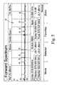
- FIG. 5 illustrates a DOCSIS 3.1 OFDM channel with some of the projecting pilot carriers of the channel
- FIG. 6 illustrates a table including settings for determining the location of a pilot carrier of the channel of FIG. 5 ;
- FIG. 7 illustrates the detection of a cyclic prefix of a DOCSIS 3.1 OFDM channel.
- This application describes three methods for detecting signal egress, generally referred to herein and elsewhere as leakage, from a hybrid fiber coaxial (HFC) system.
- the first method uses current equipment and only requires a configuration change to enable monitoring of the DOCSIS 3.1 signal permitted in the specification.
- the other two methods involve detecting a particular component of the DOCSIS 3.1 signal, generally referred to hereinafter and elsewhere as “pilot” carriers. These two methods are specific to the detection of the presence of the pilot carrier component, although these methods could be used to detect the presence of only pilot carrier type signals broadcast within the system.
- pilot carriers are currently required to transmit attributes of the signal being broadcast to receivers further out in the system.
- These signals are currently transmitted using binary phase shift keying, or BPSK, modulation, but these methods could be used to detect other types of modulation as well.
- each method may be used in combination with any of the other methods to provide a single, overall leakage detection technique.
- the first method (1) is the most straightforward to implement because it involves only a special configuration of the DOCSIS 3.1 channel.
- an exclusion band 20 may be created by removing some OFDM subcarriers and treating the spaces previously occupied by the removed OFDM subcarriers as “unused” in the channel.
- a DOCSIS 3.1 OFDM channel 22 occupies a space of 138 MHz, and an exclusion band 20 has been created around 612 MHz, as shown in FIG. 3 .
- “Exclusion bands” are defined as notches of spectrum (subcarriers) within the DOCSIS 3.1 OFDM carrier that are unused.
- a device such as, for example, a Trilithic CT-4 Digital Leakage Tagger can be used to insert one or more test carriers 24 at about the remaining subcarriers' power levels.
- the exclusion band 20 is shown in detail with one or more test carriers 24 inserted.
- the inserted test carriers 24 are ideally placed in locations where there are no off-air signals. This placement reduces the chance of other signals interfering with the detection by the leakage instrument of egress of the inserted test carriers.
- a user may insert the CT-4 tagger carrier at 612 MHz at ⁇ 30 dB from the total power of an adjacent 6 MHz chunk of spectrum.
- the user may then configure the Cable Modem Termination System (CMTS) at the broadcaster's headend to remove subcarriers from the area around 612 MHz, as shown in FIG. 4 , to create an exclusion band without affecting the adjacent subcarriers.
- CMTS Cable Modem Termination System
- up to five subcarriers may be removed (250 kHz) without any subcarrier Modulation Error Ratio (MER) degradation such that a 190 MHz maximum bandwidth DOCSIS 3.1 channel in 4K mode with the 5 subcarrier exclusion band causes only a 0.13% of data capacity reduction.
- a 3 subcarrier exclusion band may be created to cause only a 0.08% data capacity reduction.
- the second method (2) requires no inserted carriers from a tagger-type device. Instead, it examines the continuous pilot carriers present in a DOCSIS 3.1 system to determine the source of the leakage.
- the DOCSIS 3.1 specification defines “continuous pilots” as pilots that occur at the same subcarrier location in every symbol and are needed for receiver synchronization.
- the pilot carriers are boosted by 6 dB over all other sub carriers in the OFDM signal or channel. This boosting enables easier location and detection of the continuous pilots.
- a DOCSIS 3.1 OFDM channel 30 includes a number of subcarriers 32 located around—10 dB.
- the second method detects the presence of the sidebands or power signatures generated by the BPSK modulation by determining if, within a frequency/spectral view of the signal bandwidth, two such sidebands are present at a particular spacing from each other.
- This method can be further enhanced by checking for amplitude matching between the two sidebands.
- This method can be further enhanced by determining that a carrier frequency was also present at half the distance between the sidebands. If the amplitude difference is known for this signal, then this method could be further enhanced by ensuring the carrier frequency amplitude difference from either sideband is correct within the received signal.
- these additional attributes of the signal become additional means for satisfying the investigator that a signal originates from a particular broadcaster in a situation where signals from multiple broadcasters are present at the same time. If all of these attributes match the attributes of the system being monitored, then it becomes much more likely that detected signal leakage originates from a particular system and can be reported as signal leakage from that system.
- the second method detects the unique signatures of the continuous pilot carriers 34 to identify the leakage source.
- a user may determine the exact frequency location of one of the continuous pilot carriers 34 based on the Cyclic Prefix Setting, Fast Fourier Transform (FFT) size, and continuous pilot location relative to the subcarrier index (n), which are set by each broadcaster system.
- FFT Fast Fourier Transform
- n the subcarrier index
- the location of a pilot carrier 34 relative to a particular subcarrier center frequency may be calculated from a 5 ⁇ -second Cyclic Prefix and a 4096 FFT size. It should be appreciate that table 40 represents only one possible setting combination for the DOCSIS 3.1 channel.
- other setting combinations may be used to generate hundreds of possible locations for pilot signals.
- a person of ordinary skill may select the setting combination of Cyclic Prefix, FFt Size, and Pilot Location associated with the target system in order to detect any leakage.
- the third method (3) involves repeatedly receiving a portion of the OFDM channel and using time correlation to detect the cyclic prefix.
- this method detects the presence of particular known and recurring data signal within the subcarriers by means of time-based correlation. Beginning with the assumption that we know a desired/ideal and recurring time-based signal within the data stream being broadcast, we can compare the incoming signal time-based samples to the expected ideal signal. If the sample size is large enough and the ideal signal is substantially different than all other received signals, then correlating/comparing the ideal signal to the received signal will produce higher response for received signals with characteristics similar to the ideal signal than those for, say, random noise or even other non-random signals that are substantially different.
- the correlation is long enough in terms of samples, then it is also possible to detect these signals even in the presence of substantial and otherwise disabling levels of noise. This higher correlation response can then be recognized from other responses and used to indicate signal leakage from the system. Given that, the ideal signal will include data potentially unique to a particular system, then the response of the detector will likely indicate signal leakage from that particular system.
- This third method takes advantage of the cyclic prefix mechanism to detect the presence of a particular DOCSIS 3.1 signal as the source of signal leakage. If a time-based correlation of the received signal is performed with a time-delayed version of the received signal, then strong correlation peaks will be observed at the new OFDM symbol width. For example, if the original OFDM symbol is 20 ⁇ -seconds long, the addition of a 5 ⁇ -second cyclic prefix will make the new OFDM symbol 25 ⁇ -seconds long. A user may configure a receiver to correlate the currently received signal with a copy of the received signal from the previous 20 ⁇ -seconds, which corresponds to the original OFDM symbol.
- FIG. 7 illustrates the detection of a cyclic prefix 50 in a real signal generated by a particular system.
- the cyclic prefix 50 occurs every 750 samples, or 25 ⁇ sec.
- N is the FFT size and n is the number of samples.
- the FFT size is equal to 4096.
- Avg ⁇ ⁇ 1 ⁇ ( n ) sum ⁇ ( Xcorr ⁇ ( n : n - Ncp - 1 ) ) Ncp ( 2 )
- Ncp is the cyclic prefix length multiplied times the FFT size (N) and n is the number of samples.
Landscapes
- Engineering & Computer Science (AREA)
- Computer Networks & Wireless Communication (AREA)
- Signal Processing (AREA)
- Monitoring And Testing Of Transmission In General (AREA)
- Mobile Radio Communication Systems (AREA)
Abstract
Description
Xcorr(n)=x(n)*conj(x(n−N)) (1)
Claims (3)
Priority Applications (1)
| Application Number | Priority Date | Filing Date | Title |
|---|---|---|---|
| US15/548,571 US10187112B2 (en) | 2015-02-04 | 2016-02-04 | Leakage detection in DOCSIS 3.1 environment |
Applications Claiming Priority (3)
| Application Number | Priority Date | Filing Date | Title |
|---|---|---|---|
| US201562111838P | 2015-02-04 | 2015-02-04 | |
| PCT/US2016/016568 WO2016126943A1 (en) | 2015-02-04 | 2016-02-04 | Leakage detection in docsis 3.1 environment |
| US15/548,571 US10187112B2 (en) | 2015-02-04 | 2016-02-04 | Leakage detection in DOCSIS 3.1 environment |
Publications (2)
| Publication Number | Publication Date |
|---|---|
| US20180019786A1 US20180019786A1 (en) | 2018-01-18 |
| US10187112B2 true US10187112B2 (en) | 2019-01-22 |
Family
ID=56564693
Family Applications (1)
| Application Number | Title | Priority Date | Filing Date |
|---|---|---|---|
| US15/548,571 Active US10187112B2 (en) | 2015-02-04 | 2016-02-04 | Leakage detection in DOCSIS 3.1 environment |
Country Status (3)
| Country | Link |
|---|---|
| US (1) | US10187112B2 (en) |
| CA (1) | CA2975872C (en) |
| WO (1) | WO2016126943A1 (en) |
Families Citing this family (1)
| Publication number | Priority date | Publication date | Assignee | Title |
|---|---|---|---|---|
| US9882663B2 (en) | 2016-03-17 | 2018-01-30 | Arcom Digital, Llc | Doppler location of signal leaks in an HFC network |
Citations (11)
| Publication number | Priority date | Publication date | Assignee | Title |
|---|---|---|---|---|
| US20030206674A1 (en) * | 2002-05-02 | 2003-11-06 | Lucent Technologies Inc. | Method and apparatus for controlling the extinction ratio of transmitters |
| US20090243394A1 (en) * | 2008-03-28 | 2009-10-01 | Nigelpower, Llc | Tuning and Gain Control in Electro-Magnetic power systems |
| US20090297140A1 (en) * | 2008-05-29 | 2009-12-03 | Actena Llc | Measuring chromatic dispersion in an optical wavelength channel of an optical fiber link |
| US20100034542A1 (en) * | 2007-01-29 | 2010-02-11 | Ofidium Pty Ltd | Methods and apparatus for generation and transmission of optical signals |
| US20110043640A1 (en) * | 2009-08-18 | 2011-02-24 | Arcom Digital, Llc | Methods and apparatus for detecting and locating leakage of digital signals |
| US20110267474A1 (en) | 2010-04-29 | 2011-11-03 | Kabelkom Sp. Z O.O. | Method of tagging signals used for leakage detection and measurement in cable television networks and apparatus for detection and/or measurement of leakage sources tagged with this method |
| US20120076331A1 (en) * | 2010-09-27 | 2012-03-29 | Siemens Medical Instruments Pte. Ltd. | Method for reconstructing a speech signal and hearing device |
| WO2014062649A2 (en) | 2012-10-15 | 2014-04-24 | Trilithic, Inc. | Icon-based home certification, in-home leakage testing, and antenna matching pad |
| US20140294052A1 (en) * | 2013-03-28 | 2014-10-02 | Broadcom Corporation | Communication system with proactive network maintenance and methods for use therewith |
| US20150311923A1 (en) * | 2014-04-25 | 2015-10-29 | Qualcomm Incorporated | Techniques for differentiating between signals of different radio access technologies |
| US20150358106A1 (en) * | 2014-06-09 | 2015-12-10 | Allen LeRoy Limberg | Conveying metadata by modulation of pilot carriers in COFDM broadcasting |
-
2016
- 2016-02-04 WO PCT/US2016/016568 patent/WO2016126943A1/en active Application Filing
- 2016-02-04 CA CA2975872A patent/CA2975872C/en active Active
- 2016-02-04 US US15/548,571 patent/US10187112B2/en active Active
Patent Citations (11)
| Publication number | Priority date | Publication date | Assignee | Title |
|---|---|---|---|---|
| US20030206674A1 (en) * | 2002-05-02 | 2003-11-06 | Lucent Technologies Inc. | Method and apparatus for controlling the extinction ratio of transmitters |
| US20100034542A1 (en) * | 2007-01-29 | 2010-02-11 | Ofidium Pty Ltd | Methods and apparatus for generation and transmission of optical signals |
| US20090243394A1 (en) * | 2008-03-28 | 2009-10-01 | Nigelpower, Llc | Tuning and Gain Control in Electro-Magnetic power systems |
| US20090297140A1 (en) * | 2008-05-29 | 2009-12-03 | Actena Llc | Measuring chromatic dispersion in an optical wavelength channel of an optical fiber link |
| US20110043640A1 (en) * | 2009-08-18 | 2011-02-24 | Arcom Digital, Llc | Methods and apparatus for detecting and locating leakage of digital signals |
| US20110267474A1 (en) | 2010-04-29 | 2011-11-03 | Kabelkom Sp. Z O.O. | Method of tagging signals used for leakage detection and measurement in cable television networks and apparatus for detection and/or measurement of leakage sources tagged with this method |
| US20120076331A1 (en) * | 2010-09-27 | 2012-03-29 | Siemens Medical Instruments Pte. Ltd. | Method for reconstructing a speech signal and hearing device |
| WO2014062649A2 (en) | 2012-10-15 | 2014-04-24 | Trilithic, Inc. | Icon-based home certification, in-home leakage testing, and antenna matching pad |
| US20140294052A1 (en) * | 2013-03-28 | 2014-10-02 | Broadcom Corporation | Communication system with proactive network maintenance and methods for use therewith |
| US20150311923A1 (en) * | 2014-04-25 | 2015-10-29 | Qualcomm Incorporated | Techniques for differentiating between signals of different radio access technologies |
| US20150358106A1 (en) * | 2014-06-09 | 2015-12-10 | Allen LeRoy Limberg | Conveying metadata by modulation of pilot carriers in COFDM broadcasting |
Non-Patent Citations (1)
| Title |
|---|
| PCT International Search Report and Written Opinion for PCT/US2016/016568, completed Jun. 10, 2016. |
Also Published As
| Publication number | Publication date |
|---|---|
| US20180019786A1 (en) | 2018-01-18 |
| CA2975872A1 (en) | 2016-08-11 |
| WO2016126943A1 (en) | 2016-08-11 |
| CA2975872C (en) | 2023-07-04 |
Similar Documents
| Publication | Publication Date | Title |
|---|---|---|
| CA2646967C (en) | Ofdma based on cognitive radio | |
| US10911276B2 (en) | Transmitter, receiver and methods and computer readable medium | |
| US10404507B2 (en) | Implicit signaling in OFDM preamble with embedded signature sequence, and cyclic prefix and postfix aided signature detection | |
| EP1959625A1 (en) | Receiver apparatus for detecting narrowband interference in a multi-carrier receive signal | |
| US7860177B2 (en) | Receiver detecting signals based on spectrum characteristic and detecting method thereof | |
| KR100376803B1 (en) | Apparatus for compensating frequency offset and method thereof in orthogonal frequency division multiplexing system | |
| WO2015200785A1 (en) | Downstream ofdm signal egress detection | |
| US8265200B2 (en) | Method and system for receiver synchronization | |
| EP1983674A1 (en) | Ofdm demodulation device and method | |
| US11070308B2 (en) | Mitigation of partial band jamming for satellite communications | |
| KR20050101253A (en) | Method and device for searching cell in ofdma systems | |
| US9210002B2 (en) | Transmitter, receiver, and controlling method thereof | |
| EP2806610A1 (en) | Coarse symbol boundary detection in ofdm receivers | |
| WO2009083336A1 (en) | Identifying a sequence of received signals | |
| US9100226B2 (en) | Robust sensing of DVB-T/H transmissions in the presence of frequency offsets | |
| WO2014171341A1 (en) | Reception apparatus, reception method, and program | |
| US10187112B2 (en) | Leakage detection in DOCSIS 3.1 environment | |
| US7158475B1 (en) | Transmitting apparatus and method and provision medium | |
| US7020074B1 (en) | Synchronization method and apparatus for frequency division multiplexed telecommunication systems | |
| US6928046B1 (en) | Frame synchronization of an OFDM signal | |
| WO2014091198A1 (en) | Data processing apparatus and method for reduction of papr in multi-carrier transmission systems | |
| US9203670B2 (en) | Frame structure for terrestrial cloud broadcast and a method of receiving the same | |
| JP3793534B2 (en) | OFDM receiving apparatus and OFDM signal receiving method | |
| KR20080001940A (en) | Apparatus for receiving braodcasting signals and method thereof | |
| US8867634B2 (en) | Method and appratus for spectrum sensing for OFDM systems employing pilot tones |
Legal Events
| Date | Code | Title | Description |
|---|---|---|---|
| FEPP | Fee payment procedure |
Free format text: ENTITY STATUS SET TO SMALL (ORIGINAL EVENT CODE: SMAL); ENTITY STATUS OF PATENT OWNER: LARGE ENTITY Free format text: ENTITY STATUS SET TO SMALL (ORIGINAL EVENT CODE: SMAL); ENTITY STATUS OF PATENT OWNER: SMALL ENTITY |
|
| AS | Assignment |
Owner name: VIAVI SOLUTIONS, INC., CALIFORNIA Free format text: ASSIGNMENT OF ASSIGNORS INTEREST;ASSIGNOR:TRILITHIC, INC.;REEL/FRAME:044756/0836 Effective date: 20180116 |
|
| STCF | Information on status: patent grant |
Free format text: PATENTED CASE |
|
| AS | Assignment |
Owner name: WELLS FARGO BANK, NATIONAL ASSOCIATION, AS ADMINISTRATIVE AGENT, COLORADO Free format text: SECURITY INTEREST;ASSIGNORS:VIAVI SOLUTIONS INC.;3Z TELECOM, INC.;ACTERNA LLC;AND OTHERS;REEL/FRAME:052729/0321 Effective date: 20200519 |
|
| AS | Assignment |
Owner name: RPC PHOTONICS, INC., NEW YORK Free format text: TERMINATIONS OF SECURITY INTEREST AT REEL 052729, FRAME 0321;ASSIGNOR:WELLS FARGO BANK, NATIONAL ASSOCIATION, AS ADMINISTRATIVE AGENT;REEL/FRAME:058666/0639 Effective date: 20211229 Owner name: VIAVI SOLUTIONS INC., CALIFORNIA Free format text: TERMINATIONS OF SECURITY INTEREST AT REEL 052729, FRAME 0321;ASSIGNOR:WELLS FARGO BANK, NATIONAL ASSOCIATION, AS ADMINISTRATIVE AGENT;REEL/FRAME:058666/0639 Effective date: 20211229 |
|
| FEPP | Fee payment procedure |
Free format text: ENTITY STATUS SET TO UNDISCOUNTED (ORIGINAL EVENT CODE: BIG.); ENTITY STATUS OF PATENT OWNER: LARGE ENTITY |
|
| MAFP | Maintenance fee payment |
Free format text: PAYMENT OF MAINTENANCE FEE, 4TH YEAR, LARGE ENTITY (ORIGINAL EVENT CODE: M1551); ENTITY STATUS OF PATENT OWNER: LARGE ENTITY Year of fee payment: 4 |