US10174716B2 - Gas turbine engine with axial movable fan variable area nozzle - Google Patents
Gas turbine engine with axial movable fan variable area nozzle Download PDFInfo
- Publication number
- US10174716B2 US10174716B2 US15/712,251 US201715712251A US10174716B2 US 10174716 B2 US10174716 B2 US 10174716B2 US 201715712251 A US201715712251 A US 201715712251A US 10174716 B2 US10174716 B2 US 10174716B2
- Authority
- US
- United States
- Prior art keywords
- fan
- nozzle
- area
- variable area
- turbofan engine
- Prior art date
- Legal status (The legal status is an assumption and is not a legal conclusion. Google has not performed a legal analysis and makes no representation as to the accuracy of the status listed.)
- Active
Links
Images


Classifications
-
- F—MECHANICAL ENGINEERING; LIGHTING; HEATING; WEAPONS; BLASTING
- F02—COMBUSTION ENGINES; HOT-GAS OR COMBUSTION-PRODUCT ENGINE PLANTS
- F02K—JET-PROPULSION PLANTS
- F02K1/00—Plants characterised by the form or arrangement of the jet pipe or nozzle; Jet pipes or nozzles peculiar thereto
- F02K1/06—Varying effective area of jet pipe or nozzle
- F02K1/15—Control or regulation
- F02K1/18—Control or regulation automatic
-
- B—PERFORMING OPERATIONS; TRANSPORTING
- B64—AIRCRAFT; AVIATION; COSMONAUTICS
- B64D—EQUIPMENT FOR FITTING IN OR TO AIRCRAFT; FLIGHT SUITS; PARACHUTES; ARRANGEMENTS OR MOUNTING OF POWER PLANTS OR PROPULSION TRANSMISSIONS IN AIRCRAFT
- B64D27/00—Arrangement or mounting of power plant in aircraft; Aircraft characterised thereby
- B64D27/02—Aircraft characterised by the type or position of power plant
- B64D27/16—Aircraft characterised by the type or position of power plant of jet type
-
- B—PERFORMING OPERATIONS; TRANSPORTING
- B64—AIRCRAFT; AVIATION; COSMONAUTICS
- B64D—EQUIPMENT FOR FITTING IN OR TO AIRCRAFT; FLIGHT SUITS; PARACHUTES; ARRANGEMENTS OR MOUNTING OF POWER PLANTS OR PROPULSION TRANSMISSIONS IN AIRCRAFT
- B64D31/00—Power plant control; Arrangement thereof
-
- B—PERFORMING OPERATIONS; TRANSPORTING
- B64—AIRCRAFT; AVIATION; COSMONAUTICS
- B64D—EQUIPMENT FOR FITTING IN OR TO AIRCRAFT; FLIGHT SUITS; PARACHUTES; ARRANGEMENTS OR MOUNTING OF POWER PLANTS OR PROPULSION TRANSMISSIONS IN AIRCRAFT
- B64D33/00—Arrangements in aircraft of power plant parts or auxiliaries not otherwise provided for
- B64D33/04—Arrangements in aircraft of power plant parts or auxiliaries not otherwise provided for of exhaust outlets or jet pipes
-
- F—MECHANICAL ENGINEERING; LIGHTING; HEATING; WEAPONS; BLASTING
- F01—MACHINES OR ENGINES IN GENERAL; ENGINE PLANTS IN GENERAL; STEAM ENGINES
- F01D—NON-POSITIVE DISPLACEMENT MACHINES OR ENGINES, e.g. STEAM TURBINES
- F01D25/00—Component parts, details, or accessories, not provided for in, or of interest apart from, other groups
- F01D25/24—Casings; Casing parts, e.g. diaphragms, casing fastenings
-
- F—MECHANICAL ENGINEERING; LIGHTING; HEATING; WEAPONS; BLASTING
- F01—MACHINES OR ENGINES IN GENERAL; ENGINE PLANTS IN GENERAL; STEAM ENGINES
- F01D—NON-POSITIVE DISPLACEMENT MACHINES OR ENGINES, e.g. STEAM TURBINES
- F01D5/00—Blades; Blade-carrying members; Heating, heat-insulating, cooling or antivibration means on the blades or the members
- F01D5/02—Blade-carrying members, e.g. rotors
- F01D5/06—Rotors for more than one axial stage, e.g. of drum or multiple disc type; Details thereof, e.g. shafts, shaft connections
-
- F—MECHANICAL ENGINEERING; LIGHTING; HEATING; WEAPONS; BLASTING
- F02—COMBUSTION ENGINES; HOT-GAS OR COMBUSTION-PRODUCT ENGINE PLANTS
- F02C—GAS-TURBINE PLANTS; AIR INTAKES FOR JET-PROPULSION PLANTS; CONTROLLING FUEL SUPPLY IN AIR-BREATHING JET-PROPULSION PLANTS
- F02C7/00—Features, components parts, details or accessories, not provided for in, or of interest apart form groups F02C1/00 - F02C6/00; Air intakes for jet-propulsion plants
- F02C7/36—Power transmission arrangements between the different shafts of the gas turbine plant, or between the gas-turbine plant and the power user
-
- F—MECHANICAL ENGINEERING; LIGHTING; HEATING; WEAPONS; BLASTING
- F02—COMBUSTION ENGINES; HOT-GAS OR COMBUSTION-PRODUCT ENGINE PLANTS
- F02K—JET-PROPULSION PLANTS
- F02K1/00—Plants characterised by the form or arrangement of the jet pipe or nozzle; Jet pipes or nozzles peculiar thereto
- F02K1/28—Plants characterised by the form or arrangement of the jet pipe or nozzle; Jet pipes or nozzles peculiar thereto using fluid jets to influence the jet flow
- F02K1/30—Plants characterised by the form or arrangement of the jet pipe or nozzle; Jet pipes or nozzles peculiar thereto using fluid jets to influence the jet flow for varying effective area of jet pipe or nozzle
-
- F—MECHANICAL ENGINEERING; LIGHTING; HEATING; WEAPONS; BLASTING
- F02—COMBUSTION ENGINES; HOT-GAS OR COMBUSTION-PRODUCT ENGINE PLANTS
- F02K—JET-PROPULSION PLANTS
- F02K1/00—Plants characterised by the form or arrangement of the jet pipe or nozzle; Jet pipes or nozzles peculiar thereto
- F02K1/54—Nozzles having means for reversing jet thrust
- F02K1/64—Reversing fan flow
- F02K1/70—Reversing fan flow using thrust reverser flaps or doors mounted on the fan housing
- F02K1/72—Reversing fan flow using thrust reverser flaps or doors mounted on the fan housing the aft end of the fan housing being movable to uncover openings in the fan housing for the reversed flow
-
- F—MECHANICAL ENGINEERING; LIGHTING; HEATING; WEAPONS; BLASTING
- F02—COMBUSTION ENGINES; HOT-GAS OR COMBUSTION-PRODUCT ENGINE PLANTS
- F02K—JET-PROPULSION PLANTS
- F02K3/00—Plants including a gas turbine driving a compressor or a ducted fan
- F02K3/02—Plants including a gas turbine driving a compressor or a ducted fan in which part of the working fluid by-passes the turbine and combustion chamber
- F02K3/04—Plants including a gas turbine driving a compressor or a ducted fan in which part of the working fluid by-passes the turbine and combustion chamber the plant including ducted fans, i.e. fans with high volume, low pressure outputs, for augmenting the jet thrust, e.g. of double-flow type
- F02K3/06—Plants including a gas turbine driving a compressor or a ducted fan in which part of the working fluid by-passes the turbine and combustion chamber the plant including ducted fans, i.e. fans with high volume, low pressure outputs, for augmenting the jet thrust, e.g. of double-flow type with front fan
-
- F—MECHANICAL ENGINEERING; LIGHTING; HEATING; WEAPONS; BLASTING
- F04—POSITIVE - DISPLACEMENT MACHINES FOR LIQUIDS; PUMPS FOR LIQUIDS OR ELASTIC FLUIDS
- F04D—NON-POSITIVE-DISPLACEMENT PUMPS
- F04D29/00—Details, component parts, or accessories
- F04D29/26—Rotors specially for elastic fluids
- F04D29/32—Rotors specially for elastic fluids for axial flow pumps
- F04D29/321—Rotors specially for elastic fluids for axial flow pumps for axial flow compressors
-
- F—MECHANICAL ENGINEERING; LIGHTING; HEATING; WEAPONS; BLASTING
- F04—POSITIVE - DISPLACEMENT MACHINES FOR LIQUIDS; PUMPS FOR LIQUIDS OR ELASTIC FLUIDS
- F04D—NON-POSITIVE-DISPLACEMENT PUMPS
- F04D29/00—Details, component parts, or accessories
- F04D29/26—Rotors specially for elastic fluids
- F04D29/32—Rotors specially for elastic fluids for axial flow pumps
- F04D29/325—Rotors specially for elastic fluids for axial flow pumps for axial flow fans
-
- F—MECHANICAL ENGINEERING; LIGHTING; HEATING; WEAPONS; BLASTING
- F04—POSITIVE - DISPLACEMENT MACHINES FOR LIQUIDS; PUMPS FOR LIQUIDS OR ELASTIC FLUIDS
- F04D—NON-POSITIVE-DISPLACEMENT PUMPS
- F04D29/00—Details, component parts, or accessories
- F04D29/26—Rotors specially for elastic fluids
- F04D29/32—Rotors specially for elastic fluids for axial flow pumps
- F04D29/38—Blades
-
- F—MECHANICAL ENGINEERING; LIGHTING; HEATING; WEAPONS; BLASTING
- F04—POSITIVE - DISPLACEMENT MACHINES FOR LIQUIDS; PUMPS FOR LIQUIDS OR ELASTIC FLUIDS
- F04D—NON-POSITIVE-DISPLACEMENT PUMPS
- F04D29/00—Details, component parts, or accessories
- F04D29/40—Casings; Connections of working fluid
- F04D29/52—Casings; Connections of working fluid for axial pumps
- F04D29/522—Casings; Connections of working fluid for axial pumps especially adapted for elastic fluid pumps
-
- F—MECHANICAL ENGINEERING; LIGHTING; HEATING; WEAPONS; BLASTING
- F04—POSITIVE - DISPLACEMENT MACHINES FOR LIQUIDS; PUMPS FOR LIQUIDS OR ELASTIC FLUIDS
- F04D—NON-POSITIVE-DISPLACEMENT PUMPS
- F04D29/00—Details, component parts, or accessories
- F04D29/40—Casings; Connections of working fluid
- F04D29/52—Casings; Connections of working fluid for axial pumps
- F04D29/54—Fluid-guiding means, e.g. diffusers
- F04D29/56—Fluid-guiding means, e.g. diffusers adjustable
- F04D29/563—Fluid-guiding means, e.g. diffusers adjustable specially adapted for elastic fluid pumps
-
- F—MECHANICAL ENGINEERING; LIGHTING; HEATING; WEAPONS; BLASTING
- F05—INDEXING SCHEMES RELATING TO ENGINES OR PUMPS IN VARIOUS SUBCLASSES OF CLASSES F01-F04
- F05D—INDEXING SCHEME FOR ASPECTS RELATING TO NON-POSITIVE-DISPLACEMENT MACHINES OR ENGINES, GAS-TURBINES OR JET-PROPULSION PLANTS
- F05D2220/00—Application
- F05D2220/30—Application in turbines
- F05D2220/32—Application in turbines in gas turbines
- F05D2220/323—Application in turbines in gas turbines for aircraft propulsion, e.g. jet engines
-
- F—MECHANICAL ENGINEERING; LIGHTING; HEATING; WEAPONS; BLASTING
- F05—INDEXING SCHEMES RELATING TO ENGINES OR PUMPS IN VARIOUS SUBCLASSES OF CLASSES F01-F04
- F05D—INDEXING SCHEME FOR ASPECTS RELATING TO NON-POSITIVE-DISPLACEMENT MACHINES OR ENGINES, GAS-TURBINES OR JET-PROPULSION PLANTS
- F05D2220/00—Application
- F05D2220/30—Application in turbines
- F05D2220/36—Application in turbines specially adapted for the fan of turbofan engines
-
- F—MECHANICAL ENGINEERING; LIGHTING; HEATING; WEAPONS; BLASTING
- F05—INDEXING SCHEMES RELATING TO ENGINES OR PUMPS IN VARIOUS SUBCLASSES OF CLASSES F01-F04
- F05D—INDEXING SCHEME FOR ASPECTS RELATING TO NON-POSITIVE-DISPLACEMENT MACHINES OR ENGINES, GAS-TURBINES OR JET-PROPULSION PLANTS
- F05D2230/00—Manufacture
- F05D2230/50—Building or constructing in particular ways
-
- F—MECHANICAL ENGINEERING; LIGHTING; HEATING; WEAPONS; BLASTING
- F05—INDEXING SCHEMES RELATING TO ENGINES OR PUMPS IN VARIOUS SUBCLASSES OF CLASSES F01-F04
- F05D—INDEXING SCHEME FOR ASPECTS RELATING TO NON-POSITIVE-DISPLACEMENT MACHINES OR ENGINES, GAS-TURBINES OR JET-PROPULSION PLANTS
- F05D2240/00—Components
- F05D2240/10—Stators
- F05D2240/12—Fluid guiding means, e.g. vanes
- F05D2240/128—Nozzles
-
- F—MECHANICAL ENGINEERING; LIGHTING; HEATING; WEAPONS; BLASTING
- F05—INDEXING SCHEMES RELATING TO ENGINES OR PUMPS IN VARIOUS SUBCLASSES OF CLASSES F01-F04
- F05D—INDEXING SCHEME FOR ASPECTS RELATING TO NON-POSITIVE-DISPLACEMENT MACHINES OR ENGINES, GAS-TURBINES OR JET-PROPULSION PLANTS
- F05D2260/00—Function
- F05D2260/40—Transmission of power
- F05D2260/403—Transmission of power through the shape of the drive components
- F05D2260/4031—Transmission of power through the shape of the drive components as in toothed gearing
- F05D2260/40311—Transmission of power through the shape of the drive components as in toothed gearing of the epicyclical, planetary or differential type
-
- F—MECHANICAL ENGINEERING; LIGHTING; HEATING; WEAPONS; BLASTING
- F05—INDEXING SCHEMES RELATING TO ENGINES OR PUMPS IN VARIOUS SUBCLASSES OF CLASSES F01-F04
- F05D—INDEXING SCHEME FOR ASPECTS RELATING TO NON-POSITIVE-DISPLACEMENT MACHINES OR ENGINES, GAS-TURBINES OR JET-PROPULSION PLANTS
- F05D2270/00—Control
- F05D2270/30—Control parameters, e.g. input parameters
- F05D2270/301—Pressure
- F05D2270/3015—Pressure differential pressure
Definitions
- the present invention relates to a gas turbine engine, and more particularly to a turbofan engine having a fan variable area nozzle (VAFN) which moves axially to change a bypass flow path area thereof.
- VAFN fan variable area nozzle
- Conventional gas turbine engines generally include a fan section and a core engine with the fan section having a larger diameter than that of the core engine.
- the fan section and the core engine are disposed about a longitudinal axis and are enclosed within an engine nacelle assembly.
- Combustion gases are discharged from the core engine through a core exhaust nozzle while an annular fan flow, disposed radially outward of the primary airflow path, is discharged through an annular fan exhaust nozzle defined between a fan nacelle and a core nacelle.
- a majority of thrust is produced by the pressurized fan air discharged through the fan exhaust nozzle, the remaining thrust being provided from the combustion gases discharged through the core exhaust nozzle.
- the fan nozzles of conventional gas turbine engines have a fixed geometry.
- the fixed geometry fan nozzles are a compromise suitable for take-off and landing conditions as well as for cruise conditions.
- Some gas turbine engines have implemented fan variable area nozzles.
- the fan variable area nozzle provide a smaller fan exit nozzle diameter during cruise conditions and a larger fan exit nozzle diameter during take-off and landing conditions.
- Existing fan variable area nozzles typically utilize relatively complex mechanisms that increase overall engine weight to the extent that the increased fuel efficiency therefrom may be negated.
- a turbofan engine includes a fan variable area nozzle (VAFN) having a first fan nacelle section and a second fan nacelle section movably mounted relative the first fan nacelle section.
- the second fan nacelle section axially slides relative the fixed first fan nacelle section to change the effective area of the fan nozzle exit area.
- the VAFN changes the physical area and geometry of the bypass flow path during particular flight conditions.
- the VAFN is closed by positioning the second fan nacelle section in-line with the first fan nacelle section to define the fan nozzle exit area and is opened by moving the second fan nacelle section aftward to provide an increased fan nozzle exit area.
- the VAFN communicates with the controller to effectively vary the area defined by the fan nozzle exit area.
- the controller By adjusting the entire periphery of the second fan nacelle section in which all sectors are moved simultaneously, engine thrust and fuel economy are maximized during each flight regime by varying the fan nozzle exit area.
- engine bypass flow is selectively vectored to provide, for example only, trim balance, thrust controlled maneuvering, enhanced ground operations and short field performance.
- the present invention therefore provides an effective, lightweight fan variable area nozzle for a gas turbine engine.
- a nacelle assembly for a high-bypass gas turbine engine may include a core nacelle defined about an engine centerline axis, a fan nacelle mounted at least partially around the core nacelle to define a fan bypass flow path for a fan bypass airflow, and a fan variable area nozzle axially movable relative the fan nacelle to define an auxiliary port to vary a fan nozzle exit area and adjust a pressure ratio of the fan bypass airflow during engine operation.
- the controller may be operable to control the fan variable area nozzle to vary a fan nozzle exit area and adjust the pressure ratio of the fan bypass airflow.
- the controller may be operable to reduce the fan nozzle exit area at a cruise flight condition.
- the controller may be operable to control the aid fan nozzle exit area to reduce a fan instability.
- the fan variable area nozzle may define a trailing edge of the fan nacelle.
- the assembly may further include a controller operable to axially move the fan variable area nozzle to vary the fan nozzle exit area in response to a flight condition.
- the fan variable area nozzle may be aligned with the fan nacelle to define a closed position of the fan nozzle exit area. Additionally or alternatively, the fan variable area nozzle is axially offset from the fan nacelle to define an open position of the fan nozzle exit area.
- the nacelle assembly may further include a gear system driven by the core engine within the core nacelle to drive the fan within the fan nacelle, the gear system defines a gear reduction ratio of greater than or equal to about 2.3.
- the nacelle assembly may further include a gear system driven by the core engine within the core nacelle to drive the fan within the fan nacelle, the gear system defines a gear reduction ratio of greater than or equal to about 2.5.
- the nacelle assembly may further include a gear system driven by the core engine to drive the fan, the gear system defines a gear reduction ratio of greater than or equal to 2.5.
- the core engine may include a low pressure turbine which defines a pressure ratio that is greater than about five (5).
- the core engine may include a low pressure turbine which defines a pressure ratio that is greater than five (5).
- the bypass flow may define a bypass ratio greater than about six (6).
- the bypass flow may define a bypass ratio greater than about ten (10).
- the bypass flow may define a bypass ratio greater than ten (10).
- a gas turbine engine may include a core nacelle defined about an engine centerline axis, a fan nacelle mounted at least partially around the core nacelle to define a fan bypass flow path for a fan bypass airflow; a fan variable area nozzle axially movable relative the fan nacelle to define an auxiliary port to vary a fan nozzle exit area and adjust a pressure ratio of the fan bypass airflow during engine operation, and a controller operable to control the fan variable area nozzle to vary a fan nozzle exit area and adjust the pressure ratio of the fan bypass airflow.
- the gas turbine engine may be a direct drive turbofan engine.
- the gas turbine may further include a low spool within the core nacelle that drives a fan within the fan nacelle through a geared architecture.
- the engine may have a bypass ratio greater than 10:1 and the geared architecture may have a gear reduction ratio of greater than 2.5:1.
- FIG. 1A is a general schematic partial fragmentary view of an exemplary gas turbine engine embodiment for use with the present invention
- FIG. 1B is a rear view of the engine
- FIG. 1C is a side view of the engine integrated with a pylon
- FIG. 1D is a perspective view of the engine integrated with a pylon
- FIG. 2A is a sectional side view of the VAFN in a closed position
- FIG. 2B is a sectional side view of the VAFN in an open position
- FIG. 3 is a graph of a bypass duct normalized cross-sectional area distribution.
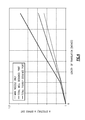
- FIG. 4 is a graph of a Effective Area Increase vs. Nozzle Translation
- FIG. 5 is a graph of a duct area distribution
- FIG. 6A is schematic geometric view of the auxiliary port location
- FIG. 6B is schematic geometric view of the auxiliary port entrance angle
- FIG. 6C is schematic geometric view of a VAFN outer surface curvature.
- FIG. 1A illustrates a general partial fragmentary schematic view of a gas turbofan engine 10 suspended from an engine pylon P within an engine nacelle assembly N as is typical of an aircraft designed for subsonic operation.
- the turbofan engine 10 includes a core engine within a core nacelle 12 that houses a low spool 14 and high spool 24 .
- the low spool 14 includes a low pressure compressor 16 and low pressure turbine 18 .
- the low spool 14 drives a fan section 20 through a gear train 22 .
- the high spool 24 includes a high pressure compressor 26 and high pressure turbine 28 .
- a combustor 30 is arranged between the high pressure compressor 26 and high pressure turbine 28 .
- the low and high spools 14 , 24 rotate about an engine axis of rotation A.
- the engine 10 is preferably a high-bypass geared architecture aircraft engine.
- the engine 10 bypass ratio is greater than about six (6) to ten (10)
- the gear train 22 is an epicyclic gear train such as a planetary gear system or other gear system with a gear reduction ratio of greater than about 2.3 and the low pressure turbine 18 has a pressure ratio that is greater than about 5.
- the engine 10 bypass ratio is greater than ten (10:1)
- the turbofan diameter is significantly larger than that of the low pressure compressor 16
- the low pressure turbine 18 has a pressure ratio that is greater than 5:1.
- the gear train 22 may be an epicycle gear train such as a planetary gear system or other gear system with a gear reduction ratio of greater than 2.5:1. It should be understood, however, that the above parameters are only exemplary of one embodiment of a geared architecture engine and that the present invention is applicable to other gas turbine engines including direct drive turbofans.
- the fan section 20 communicates airflow into the core nacelle 12 to power the low pressure compressor 16 and the high pressure compressor 26 .
- Core airflow compressed by the low pressure compressor 16 and the high pressure compressor 26 is mixed with the fuel in the combustor 30 and expanded over the high pressure turbine 28 and low pressure turbine 18 .
- the turbines 28 , 18 are coupled for rotation with, respective, spools 24 , 14 to rotationally drive the compressors 26 , 16 and through the gear train 22 , the fan section 20 in response to the expansion.
- a core engine exhaust E exits the core nacelle 12 through a core nozzle 43 defined between the core nacelle 12 and a tail cone 32 .
- the core nacelle 12 is supported within the fan nacelle 34 by structure 36 often generically referred to as Fan Exit Guide Vanes (FEGVs).
- a bypass flow path 40 is defined between the core nacelle 12 and the fan nacelle 34 .
- the engine 10 generates a high bypass flow arrangement with a bypass ratio in which approximately 80 percent of the airflow entering the fan nacelle 34 becomes bypass flow B.
- the bypass flow B communicates through the generally annular fan bypass flow path 40 and is discharged from the engine 10 through a fan variable area nozzle (VAFN) 42 which defines a fan nozzle exit area 44 between the fan nacelle 34 and the core nacelle 12 at a fan nacelle end segment 34 S of the fan nacelle 34 downstream of the fan section 20 .
- VAFN fan variable area nozzle
- Thrust is a function of density, velocity, and area. One or more of these parameters can be manipulated to vary the amount and direction of thrust provided by the bypass flow B.
- the VAFN 42 operates to effectively vary the area of the fan nozzle exit area 44 to selectively adjust the pressure ratio of the bypass flow B in response to a controller C.
- Low pressure ratio turbofans are desirable for their high propulsive efficiency. However, low pressure ratio fans may be inherently susceptible to fan stability/flutter problems at low power and low flight speeds.
- the VAFN allows the engine to change to a more favorable fan operating line at low power, avoiding the instability region, and still provide the relatively smaller nozzle area necessary to obtain a high-efficiency fan operating line at cruise.
- the fan section 20 of the engine 10 is preferably designed for a particular flight condition—typically cruise at about 0.8 M and about 35,000 feet.
- the VAFN 42 is operated to effectively vary the fan nozzle exit area 44 to adjust fan bypass air flow such that the angle of attack or incidence on the fan blades is maintained close to the design incidence for efficient engine operation at other flight conditions, such as landing and takeoff to thus provide optimized engine operation over a range of flight conditions with respect to performance and other operational parameters such as noise levels.
- the VAFN 42 is separated into at least two sectors 42 A- 42 B ( FIG. 1B ) defined between the pylon P and a lower Bi-Fi splitter L which typically interconnects a larger diameter fan duct reverser cowl and a smaller diameter core cowl ( FIGS. 1C and 1D ).
- Each of the at least two sectors 42 A- 42 B are independently adjustable to asymmetrically vary the fan nozzle exit area 44 to generate vectored thrust. It should be understood that although two segments are illustrated, any number of segments may alternatively or additionally be provided.
- the VAFN 42 communicates with a controller C or the like to adjust the fan nozzle exit area 44 in a symmetrical and asymmetrical manner.
- Other control systems including an engine controller or aircraft flight control system may also be usable with the present invention.
- By separately adjusting the circumferential sectors 42 A- 42 B of the VAFN 42 to provide an asymmetrical fan nozzle exit area 44 engine bypass flow is selectively vectored to provide, for example only, trim balance or thrust controlled maneuvering enhanced ground operations or short field performance.
- the VAFN 42 generally includes an auxiliary port assembly 50 having a first fan nacelle section 52 and a second fan nacelle section 54 movably mounted relative the first fan nacelle section 52 .
- the second fan nacelle section 54 axially slides along the engine axis A relative the fixed first fan nacelle section 52 to change the effective area of the fan nozzle exit area 44 .
- the second fan nacelle section 54 slides aftward upon a track fairing 56 A, 56 B (illustrated schematically in FIGS. 1C and 1D ) in response to an actuator 58 (illustrated schematically).
- the track fairing 56 A, 56 B extend from the first fan nacelle section 52 adjacent the respective pylon P and the lower Bi-Fi splitter L ( FIG. 1D ).
- the VAFN 42 changes the physical area and geometry of the bypass flow path 40 during particular flight conditions.
- the bypass flow B is effectively altered by sliding of the second fan nacelle section 54 relative the first fan nacelle section 52 between a closed position ( FIG. 2A ) and an open position ( FIG. 2B ).
- the auxiliary port assembly 50 is closed by positioning the second fan nacelle section 54 in-line with the first fan nacelle section 52 to define the fan nozzle exit area 44 as exit area F 0 ( FIG. 2A ).
- the VAFN 42 is opened by moving the second fan nacelle section 54 aftward along the track fairing 56 A, 56 B away from the first fan nacelle section 52 to open an auxiliary port 60 which extends between the open second fan nacelle section 54 relative the first fan nacelle section 52 to essentially provide an increased fan nozzle exit area 44 exit area F 1 . That is, the exit area F 1 with the port 60 is greater than exit area F 0 ( FIG. 2B ).
- the auxiliary port 60 is incorporated into the exhaust system of a high bypass ratio commercial turbofan engine within the bypass duct aft of the Fan Exit Guide Vanes (FEGVs; FIGS. 2A, 2B ).
- the auxiliary port 60 is located in the aft section of the bypass duct outer wall.
- the bypass duct area distribution, the effective area increase vs. translation ( FIG. 4 ), area distribution ( FIG. 5 ), and auxiliary port 60 location ( FIG. 6A ) and wall curvatures ( FIG. 6B-6C ) are tailored to provide a proper flow-field that allows the auxiliary port 60 to obtain the required additional effective exit area.
- the auxiliary port 60 will essentially double the effective area gain due to translation.
- the auxiliary port 60 provides a relatively low weight method of providing increased exit area to control the fan operating line without causing high system losses or unacceptable aircraft installation issues.
- the auxiliary port exit plane 44 B (defined as the plane between the stationary section's trailing edge and the moving sections leading edge) initially has an opening in which the exit plane normal vector is near-axial, but as the stroke increases, the normal vector becomes more inclined and approaches a near-radial vector. Once the exit plane normal has become near-radial, the maximum auxiliary port effectiveness has been reached. Once this point is reached, the rate of the effective area vs. translation changes from steep slope of the “well designed port” the shallow rate of the “main nozzle only”, since additional area will be provided through the main nozzle 44 A due to the inward slope of the core nacelle 12 . A well designed auxiliary port nozzle will achieve approximately +25% effective area before the port effectiveness limit is reached.
- the auxiliary port doubles the rate of additional effectiveness. Outside of this range, the rate of additional effectiveness may be equivalent to a translating nozzle that has no auxiliary port. Or put another way, the auxiliary port reduces the stroke necessary for a pure translating nozzle to achieve a desired effective area.
- the cross-sectional area at the auxiliary port 60 is greater than the maximum required effective area of the VAFN 42 and the bypass duct area distribution is tailored to ensure the duct cross-sectional area forward of the auxiliary port 60 is greater than the port opening cross-sectional area. This avoids a situation where an upstream internal cross-section becomes the controlling flow area (i.e. is smaller than the exit area), which can lead to operational limits and structural issues.
- the auxiliary port 60 in the disclosed embodiment is located no more forward than 0.1 DEL_X/L_DUCT defined from a point D at the largest radius Rmax of the annular fan bypass flow path 40 defined by the second fan nacelle section 54 .
- Rmax is defined through point D and perpendicular to the engine axis A.
- Point D in the disclosed non limiting embodiment is located on an inner wall surface 541 of the second fan nacelle section 54 when the second fan nacelle section 54 is in a closed position.
- DEL_X is the axial distance to the forward most point of the auxiliary port 60 from Rmax.
- L_DUCT is the overall axial length of the annular fan bypass flow path 40 .
- the angle between the mean port line and the fan duct outer wall is relatively low to provide well-behaved, low loss exit flow.
- the auxiliary port 60 entrance angle (Theta_in) relative to the fan bypass duct OD wall is less than 20 degrees ( FIG. 6B ) while the outer VAFN surface has an R_ARC/CHORD>0.7 where R_ARC is a radial distance from the engine axis A to a radial outer wall surface 54 O of the second fan nacelle section 54 and CHORD is the chord length of the second fan nacelle section 54 ( FIG. 6C ).
- the curvature of the outer wall surface 54 O near the auxiliary port 60 promotes flow through the auxiliary port 60 .
- the stroke of the second fan nacelle section 54 necessary to obtain an additional 20% effective exit area is approximately 8.4 inches.
- the VAFN 42 communicates with the controller C to move the second fan nacelle section 54 relative the first fan nacelle section 52 of the auxiliary port assembly 50 to effectively vary the area defined by the fan nozzle exit area 44 .
- Various control systems including an engine controller or an aircraft flight control system may also be usable with the present invention.
- engine thrust and fuel economy are maximized during each flight regime by varying the fan nozzle exit area.
- engine bypass flow is selectively vectored to provide, for example only, trim balance, thrust controlled maneuvering, enhanced ground operations and short field performance.
Abstract
Description
Claims (30)
Priority Applications (3)
| Application Number | Priority Date | Filing Date | Title |
|---|---|---|---|
| US15/712,251 US10174716B2 (en) | 2007-08-23 | 2017-09-22 | Gas turbine engine with axial movable fan variable area nozzle |
| US16/214,755 US11162456B2 (en) | 2007-08-23 | 2018-12-10 | Gas turbine engine with axial movable fan variable area nozzle |
| US17/326,904 US11454193B2 (en) | 2007-08-23 | 2021-05-21 | Gas turbine engine with axial movable fan variable area nozzle |
Applications Claiming Priority (4)
| Application Number | Priority Date | Filing Date | Title |
|---|---|---|---|
| US11/843,675 US8074440B2 (en) | 2007-08-23 | 2007-08-23 | Gas turbine engine with axial movable fan variable area nozzle |
| US13/314,365 US9701415B2 (en) | 2007-08-23 | 2011-12-08 | Gas turbine engine with axial movable fan variable area nozzle |
| US15/360,001 US9784212B2 (en) | 2007-08-23 | 2016-11-23 | Gas turbine engine with axial movable fan variable area nozzle |
| US15/712,251 US10174716B2 (en) | 2007-08-23 | 2017-09-22 | Gas turbine engine with axial movable fan variable area nozzle |
Related Parent Applications (1)
| Application Number | Title | Priority Date | Filing Date |
|---|---|---|---|
| US15/360,001 Continuation US9784212B2 (en) | 2007-08-23 | 2016-11-23 | Gas turbine engine with axial movable fan variable area nozzle |
Related Child Applications (1)
| Application Number | Title | Priority Date | Filing Date |
|---|---|---|---|
| US16/214,755 Continuation US11162456B2 (en) | 2007-08-23 | 2018-12-10 | Gas turbine engine with axial movable fan variable area nozzle |
Publications (2)
| Publication Number | Publication Date |
|---|---|
| US20180030925A1 US20180030925A1 (en) | 2018-02-01 |
| US10174716B2 true US10174716B2 (en) | 2019-01-08 |
Family
ID=45869233
Family Applications (10)
| Application Number | Title | Priority Date | Filing Date |
|---|---|---|---|
| US13/314,365 Active US9701415B2 (en) | 2007-08-23 | 2011-12-08 | Gas turbine engine with axial movable fan variable area nozzle |
| US15/360,001 Active US9784212B2 (en) | 2007-08-23 | 2016-11-23 | Gas turbine engine with axial movable fan variable area nozzle |
| US15/359,948 Abandoned US20170074208A1 (en) | 2007-08-23 | 2016-11-23 | Gas turbine engine with axial movable fan variable area nozzle |
| US15/360,092 Active US9771893B2 (en) | 2007-08-23 | 2016-11-23 | Gas turbine engine with axial movable fan variable area nozzle |
| US15/360,053 Active US9822732B2 (en) | 2007-08-23 | 2016-11-23 | Gas turbine engine with axial movable fan variable area nozzle |
| US15/712,238 Active US10174715B2 (en) | 2007-08-23 | 2017-09-22 | Gas turbine engine with axial movable fan variable area nozzle |
| US15/712,251 Active US10174716B2 (en) | 2007-08-23 | 2017-09-22 | Gas turbine engine with axial movable fan variable area nozzle |
| US15/729,748 Active US10087885B2 (en) | 2007-08-23 | 2017-10-11 | Gas turbine engine with axial movable fan variable area nozzle |
| US16/214,755 Active 2028-02-08 US11162456B2 (en) | 2007-08-23 | 2018-12-10 | Gas turbine engine with axial movable fan variable area nozzle |
| US17/326,904 Active US11454193B2 (en) | 2007-08-23 | 2021-05-21 | Gas turbine engine with axial movable fan variable area nozzle |
Family Applications Before (6)
| Application Number | Title | Priority Date | Filing Date |
|---|---|---|---|
| US13/314,365 Active US9701415B2 (en) | 2007-08-23 | 2011-12-08 | Gas turbine engine with axial movable fan variable area nozzle |
| US15/360,001 Active US9784212B2 (en) | 2007-08-23 | 2016-11-23 | Gas turbine engine with axial movable fan variable area nozzle |
| US15/359,948 Abandoned US20170074208A1 (en) | 2007-08-23 | 2016-11-23 | Gas turbine engine with axial movable fan variable area nozzle |
| US15/360,092 Active US9771893B2 (en) | 2007-08-23 | 2016-11-23 | Gas turbine engine with axial movable fan variable area nozzle |
| US15/360,053 Active US9822732B2 (en) | 2007-08-23 | 2016-11-23 | Gas turbine engine with axial movable fan variable area nozzle |
| US15/712,238 Active US10174715B2 (en) | 2007-08-23 | 2017-09-22 | Gas turbine engine with axial movable fan variable area nozzle |
Family Applications After (3)
| Application Number | Title | Priority Date | Filing Date |
|---|---|---|---|
| US15/729,748 Active US10087885B2 (en) | 2007-08-23 | 2017-10-11 | Gas turbine engine with axial movable fan variable area nozzle |
| US16/214,755 Active 2028-02-08 US11162456B2 (en) | 2007-08-23 | 2018-12-10 | Gas turbine engine with axial movable fan variable area nozzle |
| US17/326,904 Active US11454193B2 (en) | 2007-08-23 | 2021-05-21 | Gas turbine engine with axial movable fan variable area nozzle |
Country Status (1)
| Country | Link |
|---|---|
| US (10) | US9701415B2 (en) |
Cited By (2)
| Publication number | Priority date | Publication date | Assignee | Title |
|---|---|---|---|---|
| US11286878B2 (en) | 2020-03-31 | 2022-03-29 | Rolls-Royce North American Technologies Inc. | Variable area nozzle exhaust system with integrated thrust reverser |
| US11891964B1 (en) | 2023-08-14 | 2024-02-06 | Rolls-Royce North American Technologies Inc. | Method of manufacture of plug nozzle with thrust reverser |
Families Citing this family (38)
| Publication number | Priority date | Publication date | Assignee | Title |
|---|---|---|---|---|
| US9701415B2 (en) | 2007-08-23 | 2017-07-11 | United Technologies Corporation | Gas turbine engine with axial movable fan variable area nozzle |
| US10309232B2 (en) * | 2012-02-29 | 2019-06-04 | United Technologies Corporation | Gas turbine engine with stage dependent material selection for blades and disk |
| US9097350B2 (en) * | 2012-04-02 | 2015-08-04 | United Technologies Corporation | Axial non-contact seal |
| US9879599B2 (en) * | 2012-09-27 | 2018-01-30 | United Technologies Corporation | Nacelle anti-ice valve utilized as compressor stability bleed valve during starting |
| US10036316B2 (en) | 2012-10-02 | 2018-07-31 | United Technologies Corporation | Geared turbofan engine with high compressor exit temperature |
| WO2014055114A1 (en) * | 2012-10-02 | 2014-04-10 | United Technologies Corporation | Geared turbofan engine with high compressor exit temperature |
| US9694912B2 (en) | 2013-02-22 | 2017-07-04 | United Technologies Corporation | ATR guide pins for sliding nacelle |
| US9631578B2 (en) | 2013-02-22 | 2017-04-25 | United Technologies Corporation | Pivot thrust reverser surrounding inner surface of bypass duct |
| WO2014197033A2 (en) * | 2013-03-15 | 2014-12-11 | United Technologies Corporation | Pivot door thrust reverser |
| US10502163B2 (en) * | 2013-11-01 | 2019-12-10 | United Technologies Corporation | Geared turbofan arrangement with core split power ratio |
| FR3020658B1 (en) * | 2014-04-30 | 2020-05-15 | Safran Aircraft Engines | LUBRICATION OIL RECOVERY HOOD FOR TURBOMACHINE EQUIPMENT |
| US9869190B2 (en) | 2014-05-30 | 2018-01-16 | General Electric Company | Variable-pitch rotor with remote counterweights |
| US10072510B2 (en) | 2014-11-21 | 2018-09-11 | General Electric Company | Variable pitch fan for gas turbine engine and method of assembling the same |
| CN105756808B (en) * | 2014-12-19 | 2018-01-23 | 中国航空工业集团公司沈阳发动机设计研究所 | A kind of axial symmetry plug nozzle with afterbunring function |
| CN105756806B (en) * | 2014-12-19 | 2018-01-16 | 中国航空工业集团公司沈阳发动机设计研究所 | A kind of axisymmetric nozzle with afterbunring function |
| US10100653B2 (en) | 2015-10-08 | 2018-10-16 | General Electric Company | Variable pitch fan blade retention system |
| US10399687B2 (en) | 2015-12-03 | 2019-09-03 | The Boeing Company | Methods and apparatus to vary an air intake of aircraft engines |
| PL415184A1 (en) * | 2015-12-10 | 2017-06-19 | General Electric Company | Exhaust nozzle for the engine with gas turbine |
| US20170204739A1 (en) | 2016-01-20 | 2017-07-20 | General Electric Company | System and Method for Cleaning a Gas Turbine Engine and Related Wash Stand |
| US10730636B2 (en) * | 2016-07-18 | 2020-08-04 | Rolls-Royce North American Technologies Inc. | Integrated aircraft cooling system |
| US11053797B2 (en) | 2017-01-23 | 2021-07-06 | General Electric Company | Rotor thrust balanced turbine engine |
| US11421627B2 (en) | 2017-02-22 | 2022-08-23 | General Electric Company | Aircraft and direct drive engine under wing installation |
| US10654577B2 (en) | 2017-02-22 | 2020-05-19 | General Electric Company | Rainbow flowpath low pressure turbine rotor assembly |
| US10393065B2 (en) * | 2017-11-09 | 2019-08-27 | United Technologies Corporation | Variable nozzle apparatus |
| GB201820924D0 (en) | 2018-12-21 | 2019-02-06 | Rolls Royce Plc | Turbine engine |
| US11204037B2 (en) | 2018-12-21 | 2021-12-21 | Rolls-Royce Plc | Turbine engine |
| GB201820919D0 (en) | 2018-12-21 | 2019-02-06 | Rolls Royce Plc | Turbine engine |
| US11480111B2 (en) | 2019-05-15 | 2022-10-25 | Honeywell International Inc. | Variable area turbine nozzle and method |
| CN112343865B (en) * | 2019-08-09 | 2022-03-01 | 广东美的环境电器制造有限公司 | Air duct structure and air treatment device |
| CN111661289B (en) * | 2020-04-23 | 2022-04-15 | 武汉船用机械有限责任公司 | Method and device for identifying faults of controllable pitch propeller |
| CN111520253B (en) * | 2020-04-30 | 2021-07-27 | 玉环天润航空机械制造有限公司 | Jet engine structure for airplane based on wind power change |
| US11428160B2 (en) | 2020-12-31 | 2022-08-30 | General Electric Company | Gas turbine engine with interdigitated turbine and gear assembly |
| US11674435B2 (en) | 2021-06-29 | 2023-06-13 | General Electric Company | Levered counterweight feathering system |
| US11795964B2 (en) | 2021-07-16 | 2023-10-24 | General Electric Company | Levered counterweight feathering system |
| US20230027726A1 (en) * | 2021-07-19 | 2023-01-26 | Raytheon Technologies Corporation | High and low spool configuration for a gas turbine engine |
| US11732673B2 (en) | 2021-07-27 | 2023-08-22 | General Electric Company | Variable area exhaust nozzle system and method for control thereof |
| US11572827B1 (en) | 2021-10-15 | 2023-02-07 | General Electric Company | Unducted propulsion system |
| US11753144B2 (en) | 2021-10-15 | 2023-09-12 | General Electric Company | Unducted propulsion system |
Citations (120)
| Publication number | Priority date | Publication date | Assignee | Title |
|---|---|---|---|---|
| US2258792A (en) | 1941-04-12 | 1941-10-14 | Westinghouse Electric & Mfg Co | Turbine blading |
| US2936655A (en) | 1955-11-04 | 1960-05-17 | Gen Motors Corp | Self-aligning planetary gearing |
| US3021731A (en) | 1951-11-10 | 1962-02-20 | Wilhelm G Stoeckicht | Planetary gear transmission |
| US3194487A (en) | 1963-06-04 | 1965-07-13 | United Aircraft Corp | Noise abatement method and apparatus |
| US3287906A (en) | 1965-07-20 | 1966-11-29 | Gen Motors Corp | Cooled gas turbine vanes |
| US3352178A (en) | 1965-11-15 | 1967-11-14 | Gen Motors Corp | Planetary gearing |
| FR1503425A (en) | 1965-12-22 | 1967-11-24 | Chepos Zd Y Chemickeho A Potra | Suspended demoulding device or hydraulic ingot pincer |
| US3412560A (en) | 1966-08-03 | 1968-11-26 | Gen Motors Corp | Jet propulsion engine with cooled combustion chamber, fuel heater, and induced air-flow |
| US3747343A (en) | 1972-02-10 | 1973-07-24 | United Aircraft Corp | Low noise prop-fan |
| US3754484A (en) | 1971-01-08 | 1973-08-28 | Secr Defence | Gearing |
| US3779010A (en) | 1972-08-17 | 1973-12-18 | Gen Electric | Combined thrust reversing and throat varying mechanism for a gas turbine engine |
| US3820719A (en) | 1972-05-09 | 1974-06-28 | Rolls Royce 1971 Ltd | Gas turbine engines |
| US3892358A (en) | 1971-03-17 | 1975-07-01 | Gen Electric | Nozzle seal |
| US3932058A (en) | 1974-06-07 | 1976-01-13 | United Technologies Corporation | Control system for variable pitch fan propulsor |
| US3935558A (en) | 1974-12-11 | 1976-01-27 | United Technologies Corporation | Surge detector for turbine engines |
| US3988889A (en) | 1974-02-25 | 1976-11-02 | General Electric Company | Cowling arrangement for a turbofan engine |
| US4054030A (en) | 1976-04-29 | 1977-10-18 | General Motors Corporation | Variable cycle gas turbine engine |
| US4086761A (en) | 1976-04-26 | 1978-05-02 | The Boeing Company | Stator bypass system for turbofan engine |
| GB1516041A (en) | 1977-02-14 | 1978-06-28 | Secr Defence | Multistage axial flow compressor stators |
| US4130872A (en) | 1975-10-10 | 1978-12-19 | The United States Of America As Represented By The Secretary Of The Air Force | Method and system of controlling a jet engine for avoiding engine surge |
| US4137708A (en) | 1973-07-02 | 1979-02-06 | General Motors Corporation | Jet propulsion |
| GB2041090A (en) | 1979-01-31 | 1980-09-03 | Rolls Royce | By-pass gas turbine engines |
| US4284174A (en) | 1979-04-18 | 1981-08-18 | Avco Corporation | Emergency oil/mist system |
| US4327548A (en) | 1979-03-10 | 1982-05-04 | Rolls-Royce Limited | Gas turbine engine power plant |
| US4478551A (en) | 1981-12-08 | 1984-10-23 | United Technologies Corporation | Turbine exhaust case design |
| US4649114A (en) | 1979-10-05 | 1987-03-10 | Intermedicat Gmbh | Oxygen permeable membrane in fermenter for oxygen enrichment of broth |
| US4696156A (en) | 1986-06-03 | 1987-09-29 | United Technologies Corporation | Fuel and oil heat management system for a gas turbine engine |
| GB2189550A (en) | 1986-04-25 | 1987-10-28 | Rolls Royce | A gas turbine engine powerplant with flow control devices |
| US4922713A (en) | 1987-11-05 | 1990-05-08 | Societe Anonyme Dite Hispano-Suiza | Turbojet engine thrust reverser with variable exhaust cross-section |
| US4979362A (en) | 1989-05-17 | 1990-12-25 | Sundstrand Corporation | Aircraft engine starting and emergency power generating system |
| US5102379A (en) | 1991-03-25 | 1992-04-07 | United Technologies Corporation | Journal bearing arrangement |
| US5141400A (en) | 1991-01-25 | 1992-08-25 | General Electric Company | Wide chord fan blade |
| US5169288A (en) | 1991-09-06 | 1992-12-08 | General Electric Company | Low noise fan assembly |
| US5317877A (en) | 1992-08-03 | 1994-06-07 | General Electric Company | Intercooled turbine blade cooling air feed system |
| US5433674A (en) | 1994-04-12 | 1995-07-18 | United Technologies Corporation | Coupling system for a planetary gear train |
| US5447411A (en) | 1993-06-10 | 1995-09-05 | Martin Marietta Corporation | Light weight fan blade containment system |
| US5466198A (en) | 1993-06-11 | 1995-11-14 | United Technologies Corporation | Geared drive system for a bladed propulsor |
| US5524847A (en) | 1993-09-07 | 1996-06-11 | United Technologies Corporation | Nacelle and mounting arrangement for an aircraft engine |
| US5577381A (en) | 1994-12-06 | 1996-11-26 | United Technologies Corporation | Exhaust nozzle cooling scheme for gas turbine engine |
| US5586431A (en) | 1994-12-06 | 1996-12-24 | United Technologies Corporation | Aircraft nacelle ventilation and engine exhaust nozzle cooling |
| US5593112A (en) | 1994-12-06 | 1997-01-14 | United Technologies Corporation | Nacelle air pump for vector nozzles for aircraft |
| US5655360A (en) | 1995-05-31 | 1997-08-12 | General Electric Company | Thrust reverser with variable nozzle |
| EP0791383A1 (en) | 1996-02-26 | 1997-08-27 | Japan Gore-Tex, Inc. | An assembly for deaeration of liquids |
| US5677060A (en) | 1994-03-10 | 1997-10-14 | Societe Europeenne De Propulsion | Method for protecting products made of a refractory material against oxidation, and resulting protected products |
| US5778659A (en) | 1994-10-20 | 1998-07-14 | United Technologies Corporation | Variable area fan exhaust nozzle having mechanically separate sleeve and thrust reverser actuation systems |
| US5806302A (en) | 1996-09-24 | 1998-09-15 | Rohr, Inc. | Variable fan exhaust area nozzle for aircraft gas turbine engine with thrust reverser |
| US5833140A (en) | 1996-12-12 | 1998-11-10 | United Technologies Corporation | Variable geometry exhaust nozzle for a turbine engine |
| US5853148A (en) | 1995-12-19 | 1998-12-29 | Societe De Construction Des Avions Hurel-Dubois | Thrust reverser with adjustable section nozzle for aircraft jet engine |
| US5857836A (en) | 1996-09-10 | 1999-01-12 | Aerodyne Research, Inc. | Evaporatively cooled rotor for a gas turbine engine |
| US5915917A (en) | 1994-12-14 | 1999-06-29 | United Technologies Corporation | Compressor stall and surge control using airflow asymmetry measurement |
| US5971229A (en) | 1997-09-03 | 1999-10-26 | Perma-Tec Gmbh & Co. Kg | Automatic lubricant dispenser |
| US5975841A (en) | 1997-10-03 | 1999-11-02 | Thermal Corp. | Heat pipe cooling for turbine stators |
| US5985470A (en) | 1998-03-16 | 1999-11-16 | General Electric Company | Thermal/environmental barrier coating system for silicon-based materials |
| US6158210A (en) | 1998-12-03 | 2000-12-12 | General Electric Company | Gear driven booster |
| US6223616B1 (en) | 1999-12-22 | 2001-05-01 | United Technologies Corporation | Star gear system with lubrication circuit and lubrication method therefor |
| EP1142850A1 (en) | 2000-04-06 | 2001-10-10 | General Electric Company | Thermal/environmental barrier coating for silicon-containing materials |
| US6315815B1 (en) | 1999-12-16 | 2001-11-13 | United Technologies Corporation | Membrane based fuel deoxygenator |
| US6318070B1 (en) | 2000-03-03 | 2001-11-20 | United Technologies Corporation | Variable area nozzle for gas turbine engines driven by shape memory alloy actuators |
| US6378293B1 (en) | 1999-02-25 | 2002-04-30 | Rolls-Royce Plc | Gas turbine engine bearing arrangement |
| US6387456B1 (en) | 1999-04-15 | 2002-05-14 | General Electric Company | Silicon based substrate with environmental/thermal barrier layer |
| US20020069637A1 (en) | 2000-12-07 | 2002-06-13 | Becquerelle Samuel Raymond Germain | Speed-reducing gear unit to absorb the axial loads generated by a turbojet fan |
| US6517341B1 (en) | 1999-02-26 | 2003-02-11 | General Electric Company | Method to prevent recession loss of silica and silicon-containing materials in combustion gas environments |
| US6607165B1 (en) | 2002-06-28 | 2003-08-19 | General Electric Company | Aircraft engine mount with single thrust link |
| EP1340903A2 (en) | 2002-03-01 | 2003-09-03 | General Electric Company | Counter rotating aircraft gas turbine engine |
| US20030163984A1 (en) | 2002-03-01 | 2003-09-04 | Seda Jorge F. | Aircraft engine with inter-turbine engine frame supported counter rotating low pressure turbine rotors |
| US6709492B1 (en) | 2003-04-04 | 2004-03-23 | United Technologies Corporation | Planar membrane deoxygenator |
| US6814541B2 (en) | 2002-10-07 | 2004-11-09 | General Electric Company | Jet aircraft fan case containment design |
| EP1522710A2 (en) | 2003-10-07 | 2005-04-13 | General Electric Company | Gas turbine engine with variable pressure |
| US20050229585A1 (en) | 2001-03-03 | 2005-10-20 | Webster John R | Gas turbine engine exhaust nozzle |
| US6971229B2 (en) | 2003-02-26 | 2005-12-06 | The Nordam Group, Inc. | Confluent exhaust nozzle |
| US20050286823A1 (en) | 2004-06-24 | 2005-12-29 | Singh Anant P | Methods and apparatus for assembling a bearing assembly |
| US7021042B2 (en) | 2002-12-13 | 2006-04-04 | United Technologies Corporation | Geartrain coupling for a turbofan engine |
| US20060101807A1 (en) | 2004-11-12 | 2006-05-18 | Wood Jeffrey H | Morphing structure |
| US20060179818A1 (en) | 2005-02-15 | 2006-08-17 | Ali Merchant | Jet engine inlet-fan system and design method |
| US20060228206A1 (en) | 2005-04-07 | 2006-10-12 | General Electric Company | Low solidity turbofan |
| GB2426792A (en) | 2005-04-01 | 2006-12-06 | David Richard Hopkins | Fan with conical hub |
| WO2007038674A1 (en) | 2005-09-28 | 2007-04-05 | Entrotech Composites, Llc | Braid-reinforced composites and processes for their preparation |
| US20080003096A1 (en) | 2006-06-29 | 2008-01-03 | United Technologies Corporation | High coverage cooling hole shape |
| US20080010969A1 (en) | 2006-07-11 | 2008-01-17 | Thomas Anthony Hauer | Gas turbine engine and method of operating same |
| US20080010929A1 (en) | 1996-06-11 | 2008-01-17 | Unilin Beheer B.V., Besloten Vennootschap | Floor panels with edge connectors |
| US7328580B2 (en) | 2004-06-23 | 2008-02-12 | General Electric Company | Chevron film cooled wall |
| WO2008045049A1 (en) | 2006-10-12 | 2008-04-17 | United Technologies Corporation | Gas turbine engine with axial movable fan variable area nozzle |
| WO2008045058A1 (en) | 2006-10-12 | 2008-04-17 | United Technologies Corporation | Operational line management of low pressure compressor in a turbofan engine |
| US20080098716A1 (en) | 2006-10-31 | 2008-05-01 | Robert Joseph Orlando | Gas turbine engine assembly and methods of assembling same |
| US20080116009A1 (en) | 2006-11-22 | 2008-05-22 | United Technologies Corporation | Lubrication system with extended emergency operability |
| EP1967701A2 (en) | 2007-03-05 | 2008-09-10 | United Technologies Corporation | Flutter sensing and control system for a gas turbine engine |
| US20080317588A1 (en) | 2007-06-25 | 2008-12-25 | Grabowski Zbigniew M | Managing spool bearing load using variable area flow nozzle |
| EP2028359A2 (en) | 2007-08-23 | 2009-02-25 | United Technologies Corporation | Gas turbine engine with axial movable fan variable area nozzle |
| US20090056343A1 (en) | 2007-08-01 | 2009-03-05 | Suciu Gabriel L | Engine mounting configuration for a turbofan gas turbine engine |
| US20090097967A1 (en) | 2007-07-27 | 2009-04-16 | Smith Peter G | Gas turbine engine with variable geometry fan exit guide vane system |
| US20090208328A1 (en) | 2008-02-20 | 2009-08-20 | Stern Alfred M | Gas turbine engine with variable area fan nozzle bladder system |
| US20090226303A1 (en) | 2008-03-05 | 2009-09-10 | Grabowski Zbigniew M | Variable area fan nozzle fan flutter management system |
| US7591754B2 (en) | 2006-03-22 | 2009-09-22 | United Technologies Corporation | Epicyclic gear train integral sun gear coupling design |
| US20090277155A1 (en) | 2007-01-02 | 2009-11-12 | Airbus France | Nacelle for aircraft jet engine and aircraft including such nacelle |
| EP2138696A1 (en) | 2008-06-26 | 2009-12-30 | United Technologies Corporation | Gas turbine engine with noise attenuating variable area fan nozzle |
| US20100008764A1 (en) | 2006-10-12 | 2010-01-14 | Constantine Baltas | Gas turbine engine with a variable exit area fan nozzle, nacelle assembly of such a engine, and corresponding operating method |
| US7662059B2 (en) | 2006-10-18 | 2010-02-16 | United Technologies Corporation | Lubrication of windmilling journal bearings |
| EP2157305A2 (en) | 2008-08-19 | 2010-02-24 | United Technologies Corporation | Gas turbine engine with variable area fan nozzle |
| US20100044503A1 (en) | 2006-09-29 | 2010-02-25 | Airbus France | Jet engine nacelle for an aircraft and aircraft comprising such a nacelle |
| US20100064659A1 (en) | 2007-08-08 | 2010-03-18 | Rohr, Inc. | Translating variable area fan nozzle with split beavertail fairings |
| US20100105516A1 (en) | 2006-07-05 | 2010-04-29 | United Technologies Corporation | Coupling system for a star gear train in a gas turbine engine |
| EP2184480A2 (en) | 2008-11-05 | 2010-05-12 | Rolls-Royce plc | A gas turbine engine with variable area exhaust nozzle and method of operating such a gas turbine engine |
| US20100148396A1 (en) | 2007-04-17 | 2010-06-17 | General Electric Company | Methods of making articles having toughened and untoughened regions |
| US20100212281A1 (en) | 2009-02-26 | 2010-08-26 | United Technologies Corporation | Auxiliary pump system for fan drive gear system |
| US20100218483A1 (en) | 2009-02-27 | 2010-09-02 | United Technologies Corporation | Controlled fan stream flow bypass |
| US7806651B2 (en) | 2004-04-02 | 2010-10-05 | Mtu Aero Engines Gmbh | Method for designing a low-pressure turbine of an aircraft engine, and low-pressure turbine |
| US20100331139A1 (en) | 2009-06-25 | 2010-12-30 | United Technologies Corporation | Epicyclic gear system with superfinished journal bearing |
| US20110004388A1 (en) | 2009-07-01 | 2011-01-06 | United Technologies Corporation | Turbofan temperature control with variable area nozzle |
| US7870722B2 (en) | 2006-12-06 | 2011-01-18 | The Boeing Company | Systems and methods for passively directing aircraft engine nozzle flows |
| US7926260B2 (en) | 2006-07-05 | 2011-04-19 | United Technologies Corporation | Flexible shaft for gas turbine engine |
| US20110120078A1 (en) | 2009-11-24 | 2011-05-26 | Schwark Jr Fred W | Variable area fan nozzle track |
| US20110120080A1 (en) | 2009-11-24 | 2011-05-26 | Schwark Jr Fred W | Variable area fan nozzle cowl airfoil |
| US20110159797A1 (en) | 2009-12-31 | 2011-06-30 | Willem Beltman | Quiet System Cooling Using Coupled Optimization Between Integrated Micro Porous Absorbers And Rotors |
| US7997868B1 (en) | 2008-11-18 | 2011-08-16 | Florida Turbine Technologies, Inc. | Film cooling hole for turbine airfoil |
| US20110293423A1 (en) | 2010-05-28 | 2011-12-01 | General Electric Company | Articles which include chevron film cooling holes, and related processes |
| US20110302907A1 (en) | 2010-06-11 | 2011-12-15 | Murphy Michael J | Variable area fan nozzle |
| US20120124964A1 (en) | 2007-07-27 | 2012-05-24 | Hasel Karl L | Gas turbine engine with improved fuel efficiency |
| US8205432B2 (en) | 2007-10-03 | 2012-06-26 | United Technologies Corporation | Epicyclic gear train for turbo fan engine |
| EP2584184A2 (en) | 2011-10-17 | 2013-04-24 | Rolls-Royce plc | Variable area nozzle for gas turbine engine |
| US8997497B2 (en) | 2010-10-29 | 2015-04-07 | United Technologies Corporation | Gas turbine engine with variable area fan nozzle |
Family Cites Families (21)
| Publication number | Priority date | Publication date | Assignee | Title |
|---|---|---|---|---|
| US3664612A (en) | 1969-12-22 | 1972-05-23 | Boeing Co | Aircraft engine variable highlight inlet |
| GB1309721A (en) | 1971-01-08 | 1973-03-14 | Secr Defence | Fan |
| US3765623A (en) | 1971-10-04 | 1973-10-16 | Mc Donnell Douglas Corp | Air inlet |
| US3843277A (en) | 1973-02-14 | 1974-10-22 | Gen Electric | Sound attenuating inlet duct |
| GB1503425A (en) | 1976-08-04 | 1978-03-08 | Hallowell E | Gas turbine ducted fan jet engines for supersonic flight |
| US4240250A (en) | 1977-12-27 | 1980-12-23 | The Boeing Company | Noise reducing air inlet for gas turbine engines |
| US4206596A (en) * | 1978-09-14 | 1980-06-10 | General Motors Corporation | Dual shaft gasifier spool for two shaft gas turbine engine |
| US4220171A (en) | 1979-05-14 | 1980-09-02 | The United States Of America As Represented By The Administrator Of The National Aeronautics And Space Administration | Curved centerline air intake for a gas turbine engine |
| US4289360A (en) | 1979-08-23 | 1981-09-15 | General Electric Company | Bearing damper system |
| US4722357A (en) | 1986-04-11 | 1988-02-02 | United Technologies Corporation | Gas turbine engine nacelle |
| US5058617A (en) | 1990-07-23 | 1991-10-22 | General Electric Company | Nacelle inlet for an aircraft gas turbine engine |
| US5361580A (en) | 1993-06-18 | 1994-11-08 | General Electric Company | Gas turbine engine rotor support system |
| US5634767A (en) | 1996-03-29 | 1997-06-03 | General Electric Company | Turbine frame having spindle mounted liner |
| US6647707B2 (en) | 2000-09-05 | 2003-11-18 | Sudarshan Paul Dev | Nested core gas turbine engine |
| US20100120078A1 (en) | 2001-08-16 | 2010-05-13 | Tony Baker | Urine Stabilization System |
| US6708482B2 (en) | 2001-11-29 | 2004-03-23 | General Electric Company | Aircraft engine with inter-turbine engine frame |
| BE1017135A3 (en) | 2006-05-11 | 2008-03-04 | Hansen Transmissions Int | A GEARBOX FOR A WIND TURBINE. |
| JP4911344B2 (en) | 2006-07-04 | 2012-04-04 | 株式会社Ihi | Turbofan engine |
| US7632064B2 (en) | 2006-09-01 | 2009-12-15 | United Technologies Corporation | Variable geometry guide vane for a gas turbine engine |
| US9701415B2 (en) * | 2007-08-23 | 2017-07-11 | United Technologies Corporation | Gas turbine engine with axial movable fan variable area nozzle |
| US8128021B2 (en) | 2008-06-02 | 2012-03-06 | United Technologies Corporation | Engine mount system for a turbofan gas turbine engine |
-
2011
- 2011-12-08 US US13/314,365 patent/US9701415B2/en active Active
-
2016
- 2016-11-23 US US15/360,001 patent/US9784212B2/en active Active
- 2016-11-23 US US15/359,948 patent/US20170074208A1/en not_active Abandoned
- 2016-11-23 US US15/360,092 patent/US9771893B2/en active Active
- 2016-11-23 US US15/360,053 patent/US9822732B2/en active Active
-
2017
- 2017-09-22 US US15/712,238 patent/US10174715B2/en active Active
- 2017-09-22 US US15/712,251 patent/US10174716B2/en active Active
- 2017-10-11 US US15/729,748 patent/US10087885B2/en active Active
-
2018
- 2018-12-10 US US16/214,755 patent/US11162456B2/en active Active
-
2021
- 2021-05-21 US US17/326,904 patent/US11454193B2/en active Active
Patent Citations (131)
| Publication number | Priority date | Publication date | Assignee | Title |
|---|---|---|---|---|
| US2258792A (en) | 1941-04-12 | 1941-10-14 | Westinghouse Electric & Mfg Co | Turbine blading |
| US3021731A (en) | 1951-11-10 | 1962-02-20 | Wilhelm G Stoeckicht | Planetary gear transmission |
| US2936655A (en) | 1955-11-04 | 1960-05-17 | Gen Motors Corp | Self-aligning planetary gearing |
| US3194487A (en) | 1963-06-04 | 1965-07-13 | United Aircraft Corp | Noise abatement method and apparatus |
| US3287906A (en) | 1965-07-20 | 1966-11-29 | Gen Motors Corp | Cooled gas turbine vanes |
| US3352178A (en) | 1965-11-15 | 1967-11-14 | Gen Motors Corp | Planetary gearing |
| FR1503425A (en) | 1965-12-22 | 1967-11-24 | Chepos Zd Y Chemickeho A Potra | Suspended demoulding device or hydraulic ingot pincer |
| US3412560A (en) | 1966-08-03 | 1968-11-26 | Gen Motors Corp | Jet propulsion engine with cooled combustion chamber, fuel heater, and induced air-flow |
| US3754484A (en) | 1971-01-08 | 1973-08-28 | Secr Defence | Gearing |
| US3892358A (en) | 1971-03-17 | 1975-07-01 | Gen Electric | Nozzle seal |
| US3747343A (en) | 1972-02-10 | 1973-07-24 | United Aircraft Corp | Low noise prop-fan |
| US3820719A (en) | 1972-05-09 | 1974-06-28 | Rolls Royce 1971 Ltd | Gas turbine engines |
| US3779010A (en) | 1972-08-17 | 1973-12-18 | Gen Electric | Combined thrust reversing and throat varying mechanism for a gas turbine engine |
| US4137708A (en) | 1973-07-02 | 1979-02-06 | General Motors Corporation | Jet propulsion |
| US3988889A (en) | 1974-02-25 | 1976-11-02 | General Electric Company | Cowling arrangement for a turbofan engine |
| US3932058A (en) | 1974-06-07 | 1976-01-13 | United Technologies Corporation | Control system for variable pitch fan propulsor |
| US3935558A (en) | 1974-12-11 | 1976-01-27 | United Technologies Corporation | Surge detector for turbine engines |
| US4130872A (en) | 1975-10-10 | 1978-12-19 | The United States Of America As Represented By The Secretary Of The Air Force | Method and system of controlling a jet engine for avoiding engine surge |
| US4086761A (en) | 1976-04-26 | 1978-05-02 | The Boeing Company | Stator bypass system for turbofan engine |
| US4054030A (en) | 1976-04-29 | 1977-10-18 | General Motors Corporation | Variable cycle gas turbine engine |
| GB1516041A (en) | 1977-02-14 | 1978-06-28 | Secr Defence | Multistage axial flow compressor stators |
| GB2041090A (en) | 1979-01-31 | 1980-09-03 | Rolls Royce | By-pass gas turbine engines |
| US4327548A (en) | 1979-03-10 | 1982-05-04 | Rolls-Royce Limited | Gas turbine engine power plant |
| US4284174A (en) | 1979-04-18 | 1981-08-18 | Avco Corporation | Emergency oil/mist system |
| US4649114A (en) | 1979-10-05 | 1987-03-10 | Intermedicat Gmbh | Oxygen permeable membrane in fermenter for oxygen enrichment of broth |
| US4478551A (en) | 1981-12-08 | 1984-10-23 | United Technologies Corporation | Turbine exhaust case design |
| GB2189550A (en) | 1986-04-25 | 1987-10-28 | Rolls Royce | A gas turbine engine powerplant with flow control devices |
| US4696156A (en) | 1986-06-03 | 1987-09-29 | United Technologies Corporation | Fuel and oil heat management system for a gas turbine engine |
| US4922713A (en) | 1987-11-05 | 1990-05-08 | Societe Anonyme Dite Hispano-Suiza | Turbojet engine thrust reverser with variable exhaust cross-section |
| US4979362A (en) | 1989-05-17 | 1990-12-25 | Sundstrand Corporation | Aircraft engine starting and emergency power generating system |
| US5141400A (en) | 1991-01-25 | 1992-08-25 | General Electric Company | Wide chord fan blade |
| US5102379A (en) | 1991-03-25 | 1992-04-07 | United Technologies Corporation | Journal bearing arrangement |
| US5169288A (en) | 1991-09-06 | 1992-12-08 | General Electric Company | Low noise fan assembly |
| US5317877A (en) | 1992-08-03 | 1994-06-07 | General Electric Company | Intercooled turbine blade cooling air feed system |
| US5447411A (en) | 1993-06-10 | 1995-09-05 | Martin Marietta Corporation | Light weight fan blade containment system |
| US5466198A (en) | 1993-06-11 | 1995-11-14 | United Technologies Corporation | Geared drive system for a bladed propulsor |
| US5524847A (en) | 1993-09-07 | 1996-06-11 | United Technologies Corporation | Nacelle and mounting arrangement for an aircraft engine |
| US5677060A (en) | 1994-03-10 | 1997-10-14 | Societe Europeenne De Propulsion | Method for protecting products made of a refractory material against oxidation, and resulting protected products |
| US5433674A (en) | 1994-04-12 | 1995-07-18 | United Technologies Corporation | Coupling system for a planetary gear train |
| US5778659A (en) | 1994-10-20 | 1998-07-14 | United Technologies Corporation | Variable area fan exhaust nozzle having mechanically separate sleeve and thrust reverser actuation systems |
| US5577381A (en) | 1994-12-06 | 1996-11-26 | United Technologies Corporation | Exhaust nozzle cooling scheme for gas turbine engine |
| US5586431A (en) | 1994-12-06 | 1996-12-24 | United Technologies Corporation | Aircraft nacelle ventilation and engine exhaust nozzle cooling |
| US5593112A (en) | 1994-12-06 | 1997-01-14 | United Technologies Corporation | Nacelle air pump for vector nozzles for aircraft |
| US5915917A (en) | 1994-12-14 | 1999-06-29 | United Technologies Corporation | Compressor stall and surge control using airflow asymmetry measurement |
| US5655360A (en) | 1995-05-31 | 1997-08-12 | General Electric Company | Thrust reverser with variable nozzle |
| US5853148A (en) | 1995-12-19 | 1998-12-29 | Societe De Construction Des Avions Hurel-Dubois | Thrust reverser with adjustable section nozzle for aircraft jet engine |
| EP0791383A1 (en) | 1996-02-26 | 1997-08-27 | Japan Gore-Tex, Inc. | An assembly for deaeration of liquids |
| US20080010929A1 (en) | 1996-06-11 | 2008-01-17 | Unilin Beheer B.V., Besloten Vennootschap | Floor panels with edge connectors |
| US5857836A (en) | 1996-09-10 | 1999-01-12 | Aerodyne Research, Inc. | Evaporatively cooled rotor for a gas turbine engine |
| US5806302A (en) | 1996-09-24 | 1998-09-15 | Rohr, Inc. | Variable fan exhaust area nozzle for aircraft gas turbine engine with thrust reverser |
| US5833140A (en) | 1996-12-12 | 1998-11-10 | United Technologies Corporation | Variable geometry exhaust nozzle for a turbine engine |
| US5971229A (en) | 1997-09-03 | 1999-10-26 | Perma-Tec Gmbh & Co. Kg | Automatic lubricant dispenser |
| US5975841A (en) | 1997-10-03 | 1999-11-02 | Thermal Corp. | Heat pipe cooling for turbine stators |
| US5985470A (en) | 1998-03-16 | 1999-11-16 | General Electric Company | Thermal/environmental barrier coating system for silicon-based materials |
| US6158210A (en) | 1998-12-03 | 2000-12-12 | General Electric Company | Gear driven booster |
| US6378293B1 (en) | 1999-02-25 | 2002-04-30 | Rolls-Royce Plc | Gas turbine engine bearing arrangement |
| US6517341B1 (en) | 1999-02-26 | 2003-02-11 | General Electric Company | Method to prevent recession loss of silica and silicon-containing materials in combustion gas environments |
| US6387456B1 (en) | 1999-04-15 | 2002-05-14 | General Electric Company | Silicon based substrate with environmental/thermal barrier layer |
| US6315815B1 (en) | 1999-12-16 | 2001-11-13 | United Technologies Corporation | Membrane based fuel deoxygenator |
| US6223616B1 (en) | 1999-12-22 | 2001-05-01 | United Technologies Corporation | Star gear system with lubrication circuit and lubrication method therefor |
| US6318070B1 (en) | 2000-03-03 | 2001-11-20 | United Technologies Corporation | Variable area nozzle for gas turbine engines driven by shape memory alloy actuators |
| EP1142850A1 (en) | 2000-04-06 | 2001-10-10 | General Electric Company | Thermal/environmental barrier coating for silicon-containing materials |
| US20020069637A1 (en) | 2000-12-07 | 2002-06-13 | Becquerelle Samuel Raymond Germain | Speed-reducing gear unit to absorb the axial loads generated by a turbojet fan |
| US6622473B2 (en) | 2000-12-07 | 2003-09-23 | Hispano-Suiza | Speed-reducing gear unit to absorb the axial loads generated by a turbojet fan |
| US20050229585A1 (en) | 2001-03-03 | 2005-10-20 | Webster John R | Gas turbine engine exhaust nozzle |
| US20030163984A1 (en) | 2002-03-01 | 2003-09-04 | Seda Jorge F. | Aircraft engine with inter-turbine engine frame supported counter rotating low pressure turbine rotors |
| EP1340903A2 (en) | 2002-03-01 | 2003-09-03 | General Electric Company | Counter rotating aircraft gas turbine engine |
| US6732502B2 (en) | 2002-03-01 | 2004-05-11 | General Electric Company | Counter rotating aircraft gas turbine engine with high overall pressure ratio compressor |
| US6619030B1 (en) | 2002-03-01 | 2003-09-16 | General Electric Company | Aircraft engine with inter-turbine engine frame supported counter rotating low pressure turbine rotors |
| US6607165B1 (en) | 2002-06-28 | 2003-08-19 | General Electric Company | Aircraft engine mount with single thrust link |
| US6814541B2 (en) | 2002-10-07 | 2004-11-09 | General Electric Company | Jet aircraft fan case containment design |
| US7021042B2 (en) | 2002-12-13 | 2006-04-04 | United Technologies Corporation | Geartrain coupling for a turbofan engine |
| US6971229B2 (en) | 2003-02-26 | 2005-12-06 | The Nordam Group, Inc. | Confluent exhaust nozzle |
| US6709492B1 (en) | 2003-04-04 | 2004-03-23 | United Technologies Corporation | Planar membrane deoxygenator |
| EP1522710A2 (en) | 2003-10-07 | 2005-04-13 | General Electric Company | Gas turbine engine with variable pressure |
| US7806651B2 (en) | 2004-04-02 | 2010-10-05 | Mtu Aero Engines Gmbh | Method for designing a low-pressure turbine of an aircraft engine, and low-pressure turbine |
| US7328580B2 (en) | 2004-06-23 | 2008-02-12 | General Electric Company | Chevron film cooled wall |
| US20050286823A1 (en) | 2004-06-24 | 2005-12-29 | Singh Anant P | Methods and apparatus for assembling a bearing assembly |
| US20060101807A1 (en) | 2004-11-12 | 2006-05-18 | Wood Jeffrey H | Morphing structure |
| US20060179818A1 (en) | 2005-02-15 | 2006-08-17 | Ali Merchant | Jet engine inlet-fan system and design method |
| GB2426792A (en) | 2005-04-01 | 2006-12-06 | David Richard Hopkins | Fan with conical hub |
| US20060228206A1 (en) | 2005-04-07 | 2006-10-12 | General Electric Company | Low solidity turbofan |
| US7374403B2 (en) | 2005-04-07 | 2008-05-20 | General Electric Company | Low solidity turbofan |
| WO2007038674A1 (en) | 2005-09-28 | 2007-04-05 | Entrotech Composites, Llc | Braid-reinforced composites and processes for their preparation |
| US7591754B2 (en) | 2006-03-22 | 2009-09-22 | United Technologies Corporation | Epicyclic gear train integral sun gear coupling design |
| US7824305B2 (en) | 2006-03-22 | 2010-11-02 | United Technologies Corporation | Integral sun gear coupling |
| US20080003096A1 (en) | 2006-06-29 | 2008-01-03 | United Technologies Corporation | High coverage cooling hole shape |
| US20100105516A1 (en) | 2006-07-05 | 2010-04-29 | United Technologies Corporation | Coupling system for a star gear train in a gas turbine engine |
| US7926260B2 (en) | 2006-07-05 | 2011-04-19 | United Technologies Corporation | Flexible shaft for gas turbine engine |
| US20080010969A1 (en) | 2006-07-11 | 2008-01-17 | Thomas Anthony Hauer | Gas turbine engine and method of operating same |
| US20100044503A1 (en) | 2006-09-29 | 2010-02-25 | Airbus France | Jet engine nacelle for an aircraft and aircraft comprising such a nacelle |
| WO2008045049A1 (en) | 2006-10-12 | 2008-04-17 | United Technologies Corporation | Gas turbine engine with axial movable fan variable area nozzle |
| US20100008764A1 (en) | 2006-10-12 | 2010-01-14 | Constantine Baltas | Gas turbine engine with a variable exit area fan nozzle, nacelle assembly of such a engine, and corresponding operating method |
| WO2008045058A1 (en) | 2006-10-12 | 2008-04-17 | United Technologies Corporation | Operational line management of low pressure compressor in a turbofan engine |
| US7662059B2 (en) | 2006-10-18 | 2010-02-16 | United Technologies Corporation | Lubrication of windmilling journal bearings |
| US20080098716A1 (en) | 2006-10-31 | 2008-05-01 | Robert Joseph Orlando | Gas turbine engine assembly and methods of assembling same |
| US20080116009A1 (en) | 2006-11-22 | 2008-05-22 | United Technologies Corporation | Lubrication system with extended emergency operability |
| US7870722B2 (en) | 2006-12-06 | 2011-01-18 | The Boeing Company | Systems and methods for passively directing aircraft engine nozzle flows |
| US20090277155A1 (en) | 2007-01-02 | 2009-11-12 | Airbus France | Nacelle for aircraft jet engine and aircraft including such nacelle |
| EP1967701A2 (en) | 2007-03-05 | 2008-09-10 | United Technologies Corporation | Flutter sensing and control system for a gas turbine engine |
| US20100148396A1 (en) | 2007-04-17 | 2010-06-17 | General Electric Company | Methods of making articles having toughened and untoughened regions |
| US7950237B2 (en) | 2007-06-25 | 2011-05-31 | United Technologies Corporation | Managing spool bearing load using variable area flow nozzle |
| US20080317588A1 (en) | 2007-06-25 | 2008-12-25 | Grabowski Zbigniew M | Managing spool bearing load using variable area flow nozzle |
| US20120124964A1 (en) | 2007-07-27 | 2012-05-24 | Hasel Karl L | Gas turbine engine with improved fuel efficiency |
| US20090097967A1 (en) | 2007-07-27 | 2009-04-16 | Smith Peter G | Gas turbine engine with variable geometry fan exit guide vane system |
| US20090056343A1 (en) | 2007-08-01 | 2009-03-05 | Suciu Gabriel L | Engine mounting configuration for a turbofan gas turbine engine |
| US20100064659A1 (en) | 2007-08-08 | 2010-03-18 | Rohr, Inc. | Translating variable area fan nozzle with split beavertail fairings |
| US20110296813A1 (en) | 2007-08-08 | 2011-12-08 | Rohr, Inc. | Variable area fan nozzle with bypass flow |
| US20090053058A1 (en) | 2007-08-23 | 2009-02-26 | Kohlenberg Gregory A | Gas turbine engine with axial movable fan variable area nozzle |
| EP2028359A2 (en) | 2007-08-23 | 2009-02-25 | United Technologies Corporation | Gas turbine engine with axial movable fan variable area nozzle |
| US8205432B2 (en) | 2007-10-03 | 2012-06-26 | United Technologies Corporation | Epicyclic gear train for turbo fan engine |
| US20090208328A1 (en) | 2008-02-20 | 2009-08-20 | Stern Alfred M | Gas turbine engine with variable area fan nozzle bladder system |
| US20090226303A1 (en) | 2008-03-05 | 2009-09-10 | Grabowski Zbigniew M | Variable area fan nozzle fan flutter management system |
| EP2138696A1 (en) | 2008-06-26 | 2009-12-30 | United Technologies Corporation | Gas turbine engine with noise attenuating variable area fan nozzle |
| US20090320488A1 (en) | 2008-06-26 | 2009-12-31 | Jonathan Gilson | Gas turbine engine with noise attenuating variable area fan nozzle |
| US20100043393A1 (en) | 2008-08-19 | 2010-02-25 | Zamora Sean P | Gas turbine engine with variable area fan nozzle |
| EP2157305A2 (en) | 2008-08-19 | 2010-02-24 | United Technologies Corporation | Gas turbine engine with variable area fan nozzle |
| EP2184480A2 (en) | 2008-11-05 | 2010-05-12 | Rolls-Royce plc | A gas turbine engine with variable area exhaust nozzle and method of operating such a gas turbine engine |
| US7997868B1 (en) | 2008-11-18 | 2011-08-16 | Florida Turbine Technologies, Inc. | Film cooling hole for turbine airfoil |
| US20100212281A1 (en) | 2009-02-26 | 2010-08-26 | United Technologies Corporation | Auxiliary pump system for fan drive gear system |
| US20100218483A1 (en) | 2009-02-27 | 2010-09-02 | United Technologies Corporation | Controlled fan stream flow bypass |
| US20100331139A1 (en) | 2009-06-25 | 2010-12-30 | United Technologies Corporation | Epicyclic gear system with superfinished journal bearing |
| EP2282016A2 (en) | 2009-07-01 | 2011-02-09 | United Technologies Corporation | Turbofan temperature control with variable area nozzle |
| US20110004388A1 (en) | 2009-07-01 | 2011-01-06 | United Technologies Corporation | Turbofan temperature control with variable area nozzle |
| US20110120078A1 (en) | 2009-11-24 | 2011-05-26 | Schwark Jr Fred W | Variable area fan nozzle track |
| US20110120080A1 (en) | 2009-11-24 | 2011-05-26 | Schwark Jr Fred W | Variable area fan nozzle cowl airfoil |
| US20110159797A1 (en) | 2009-12-31 | 2011-06-30 | Willem Beltman | Quiet System Cooling Using Coupled Optimization Between Integrated Micro Porous Absorbers And Rotors |
| US20110293423A1 (en) | 2010-05-28 | 2011-12-01 | General Electric Company | Articles which include chevron film cooling holes, and related processes |
| US20110302907A1 (en) | 2010-06-11 | 2011-12-15 | Murphy Michael J | Variable area fan nozzle |
| US8997497B2 (en) | 2010-10-29 | 2015-04-07 | United Technologies Corporation | Gas turbine engine with variable area fan nozzle |
| EP2584184A2 (en) | 2011-10-17 | 2013-04-24 | Rolls-Royce plc | Variable area nozzle for gas turbine engine |
Non-Patent Citations (201)
| Title |
|---|
| "Civil Turbojet/Turbofan Specifications", Jet Engine Specification Database (Apr. 3, 2005). |
| Adams, Eric. The worlds hugest jet engine is wider than a 737's fuselage. Retrieved Apr. 28, 2016 from: www.wired.com/2016/04/worlds-hugest jet-engine-wider-737s-fuselage/ accessed. |
| Agarwal, B.D and Broutman, L.J. (1990). Analysis and performance of fiber composites, 2nd Edition. John Kiley & Sons, Inc. New York: New York. pp. 1-30, 50-51, 56-58, 60-61, 64-71, 87-89, 324-329, 436-437. |
| Anderson, N.E., Loewenthal, S.H., and Black, J.D. (1984). An analytical method to predict efficiency of aircraft gearboxes. NASA Technical Memorandum prepared for the Twentieth Joint Propulsion Conference. Cincinnati, OH. Jun. 11-13, 1984. pp. 1-25. |
| Avco Lycoming Divison. ALF 502L Maintenance Manual. Apr. 1981. pp. 1-118. |
| Aviadvigatel D-110. Jane's Aero-engines, Aero-engines-Turbofan. Jun. 1, 2010. |
| Aviadvigatel D-110. Jane's Aero-engines, Aero-engines—Turbofan. Jun. 1, 2010. |
| Baker, R.W. (2000). Membrane technology and applications. New York, NY: McGraw-Hill. pp. 87-153. |
| Bessarabov, D.G., Jacobs, E.P., Sanderson, R.D., and Beckman, I.N. (1996). Use of nonporous polymeric flat-sheet gas-separation membranes in a membrane-liquid contactor: experimental studies. Journal of Membrane Sciences, vol. 113. 1996. pp. 275-284. |
| Boggia, S. et al., Intercooled Recuperated Gas Turbine Engine Concept, AIAA 2005-4192, 2005, pp. 1-11. |
| Bornstein, N. (1993). Oxidation of advanced intermetallic compounds. Journal de Physique IV, 1993, 03 (C9), pp. C9-367-C9-373. |
| Brennan, P.J. and Kroliczek, E.J. (1979). Heat pipe design handbook. Prepared for National Aeronautics and Space Administration by B & K Engineering, Inc. Jun. 1979. pp. 1-348. |
| Brines, G.L. (1990). The turbofan of tomorrow. Mechanical Engineering: The Journal of the American Society of Mechanical Engineers,108(8), 65-67. |
| Bucknell, R.L. (1973). Influence of fuels and lubricants on turbine engine design and performance, fuel and lubricant analyses. Final Technical Report, Mar. 1971-Mar. 1973. pp. 1-252. |
| Bunker, R.S. (2005). A review of shaped hole turbine film-cooling technology. Journal of Heat Transfer vol. 127. Apr. 2005. pp. 441-453. |
| Carney, K., Pereira, M. Revilock, and Matheny, P. (2003). Jet engine fan blade containment using two alternate geometries. 4th European LS-DYNA Users Conference. pp. 1-10. |
| Cheryan, M. (1998). Ultrafiltration and microfiltration handbook. Lancaster, PA: Tecnomic Publishing Company, Inc. pp. 171-236. |
| Clarke, D.R. and Levi, C.G. (2003). Materials design for the next generation thermal barrier coatings. Annual. Rev. Mater. Res. vol. 33. 2003. pp. 383-417. |
| Coy, Peter. The little gear that could reshape the jet engine: A simple idea's almost 30-year, $10 billion journey oto the aircraft mainstream. Bloomberg Business. Oct. 15, 2015. p. 1-4. |
| Cramoisi, G. Ed. (2012). Death in the Potomac: The crash of Air Florida Flight 90. Air Crash Investigations. Accident Report NTSB/AAR-82-8. p. 45-47. |
| Cusick, M. (1981). Avco Lycoming's ALF 502 high bypass fan engine. Society of Automotive Engineers, inc. Business Aircraft Meeting & Exposition. Wichita, Kansas. Apr. 7-10, 1981. pp. 1-9. |
| Daly, M. Ed. (2010). Jane's Aero-Engine. Issue Twenty-seven. Mar. 2010. p. 633-636. |
| Darrah, S. (1987). Jet fuel deoxygenation. Interim Report for Period Mar. 1987-Jul. 1988. pp. 1-22. |
| Dassault Falcon 900EX Easy Systems Summary. Retrieved from: http://www.smartcockpit.com/docs/F900EX-Engines.pdf pp. 1-31. |
| Davies, D. and Miller, D.C. (1971). A variable pitch fan for an ultra quiet demonstrator engine. 1976 Spring Convention: Seeds for Success in Civil Aircraft Design in the Next Two Decades. pp. 1-18. |
| Decision Institution of Inter Partes Review. General Electric Co., Petitioner, v. United Technologies Corp., Patent Owner. IPR2016-00531. Patent 8,511,605. Entered Jun. 30, 2016. pp. 1-16. |
| Decision Institution of Inter Partes Review. General Electric Co., Petitioner, v. United Technologies Corp., Patent Owner. IPR2016-00533. U.S. Pat. No. 8,511,605. Entered Jun. 30, 2016. pp. 1-19. |
| Decision Institution of Inter Partes Review. General Electric Co., Petitioner, v. United Technologies Corp., Patent Owner. IPR2016-00534. Patent 8,365,513. Entered Aug. 12, 2016. pp. 1-27. |
| Decker, S. and Clough, R. (2016). GE wins shot at voiding pratt patent in jet-engine clash. Bloomberg Technology. Retrieved from: https://www.bloomberg.com/news/articles/2016-06-30/ge-wins-shot-to-invalidate-pratt-airplane-engine-patent-in-u-s. |
| Declaration of Dr. Magdy Allia. In re U.S. Pat. No. 8,313,280. Executed Oct. 21, 2016. pp. 1-88. |
| Declaration of Dr. Magdy Attia. In re U.S. Pat. No. 8,517,668. Executed Dec. 8, 2016. pp. 1-81. |
| Declaration of John Eaton, Ph.D. In re U.S. Pat. No. 8,869,568. Executed Mar. 28, 2016. pp. 1-87. |
| Declaration of Magdy Attia, Ph.D in connection with the petition for inter partes review for U.S. Pat. No. 8,365,513 executed Jan. 17, 2016. pp. 1-74. |
| Declaration of Reza Abhari, Ph.D. In re U.S. Pat. No. 8,844,265. Executed Jun. 28, 2016. pp. 1-91. |
| Declaration of Reza Abhari. In re U.S. Pat. No. 8,448,895. Executed Nov. 28. pp. 1-81. |
| Declaration of Reza Abhari. In re U.S. Pat. No. 8,695,920, claims 1-4, 7-14, 17 and 19. Executed Nov. 29. pp. 1-102. |
| Declaration of Reza Abhari. In re U.S. Pat. No. 8,695,920. Executed Nov. 30. pp. 1-67. |
| Dickey, T.A. and Dobak, E.R. (1972). The evolution and development status of ALF 502 turbofan engine. National Aerospace Engineering and Manufacturing Meeting. San Diego, California. Oct. 2-5, 1972. pp. 1-12. |
| Drago, R.J. (1974). Heavy-lift helicopter brings up drive ideas. Power Transmission Design. Mar. 1987. pp. 1-15. |
| Drago, R.J. and Margasahayam, R.N. (1987). Stress analysis of planet gears with integral bearings; 3D finite-element model development and test validation. 1987 MSC NASTRAN World Users Conference. Los Angeles, CA. Mar. 1987. pp. 1-14. |
| Dudley, D.W., Ed. (1962). Gear handbook. New York, NY: McGraw-Hill. pp. 14-17 (TOC, Preface, and Index). |
| Edkins, D.P., Hirschkron, R., and Lee, R. (1972). TF34 turbofan quiet engine study. Final Report prepared for NASA. NASA-CR-120914. Jan. 1, 1972. pp. 1-99. |
| Edwards, T. and Zabarnick, S. (1993). Supercritical fuel deposition mechanisms. Ind. Eng. Chem. Res. vol. 32. 1993. pp. 3117-3122. |
| El-Sayad, A.F. (2008). Aircraft propulsion and gas turbine engines. Boca Raton, FL: CRC Press. pp. 215-219 and 855-860. |
| European Search Report for EP Application No. 12869088.0 dated Jul. 23, 2015. |
| European Search Report for EP Application No. 12871636.2 dated Jul. 23, 2015. |
| European Search Report for EP Application No. 12871743.6 dated Jul. 14, 2015. |
| European Search Report for EP Application No. 12872220.4 dated Jul. 22, 2015. |
| European Search Report for EP Application No. 12872986.0 dated Jun. 22, 2015. |
| Faghri, A. (1995). Heat pipe and science technology. Washington, D.C.: Taylor & Francis. pp. 1-60. |
| File History for U.S. Appl. No. 12/131,876. |
| Final Written Decision General Electric Company., Petitioner, v. United Technologies Corp., Patent Owner. IPR2016-00534. U.S. Pat. No. 8,365,513. Entered Aug. 3, 2017. pp. 1-42. |
| Final Written Decision. U.S. Pat. No. 8,313,280. General Electric Company, Petitioner, v. United Technologies Corporation, Patent Owner. IPR2017-00427. Entered Jul. 3, 2018. |
| Fledderjohn, K.R. (1983). The TFE731-5: Evolution of a decade of business jet service. SAE Technical Paper Series. Business Aircraft Meeting & Exposition. Wichita, Kansas. Apr. 12-15, 1983. pp. 1-12. |
| Frankenfeld, J.W. and Taylor, W.F. (1980). Deposit fromation from deoxygenated hydrocarbons. 4. Studies in pure compound systems. Ind. Eng. Chem., Prod. Res. Dev., vol. 19(1). 1978. pp. 65-70. |
| Garret TFE731 Turbofan Engine (CAT C). Chapter 79: Lubrciation System. TTFE731 Issue 2. 2010. pp. 1-24. |
| Gates, D. Bombardier flies at higher market. Seattle Times. Jul. 13, 2008. pp. C6. |
| Gibala, R., Ghosh, A.K., Van Aken, D.C., Srolovitz, D.J., Basu, A., Chang, H., . . . Yang, W. (1992). Mechanical behavior and interface design of MoSi2-based alloys and composites. Materials Science and Engineering, A155, 1992. pp. 147-158. |
| Gliebe, P.R. and Janardan, B.A. (2003). Ultra-high bypass engine aeroacoustic study. NASA/CR-2003-21252. GE Aircraft Engines, Cincinnati, Ohio. Oct. 2003. pp. 1-103. |
| Grady, J.E., Weir, D.S., Lamoureux, M.C., and Martinez, M.M. (2007). Engine noise research in NASA's quiet aircraft technology project. Papers from the International Symposium on Air Breathing Engines (ISABE). 2007. |
| Griffiths, B. (2005). Composite fan blade containment case. Modem Machine Shop. Retrieved from: http://www.mmsonline.com/articles/composite-fan-blade-containment-case pp. 1-4. |
| Guha. Optimum Fan Pressure Ratio for Bypass Engines with Separate or Mixed Exhaust Streams. Journal of Propulsion and Power, vol. 17, No. 5. Sep.-Oct. 2001 [retrieved on Aug. 21, 2013]. Retrieved from the Internet: <URL: http://www.facweb.iitkgp,ernet.in/˜aguha/research/AIAA2001.pdf>entire document. |
| Gunston, B. (Ed). (2000). Jane's aero-engines. Issue Seven. Janes Information Group Inc. Alexandria, Virgina. pp. 1-47, 61, 464-512. |
| Gunston, B. (Ed.) (2000). Jane's aero-engines, Issue seven. Coulsdon, Surrey, UK: Jane's Information Group Limited. pp. 510-512. |
| Guynn, M. D., Berton, J.J., Fisher, K. L., Haller, W.J., Tong, M. T., and Thurman, D.R. (2011). Refined exploration of turbofan design options for an advanced single-aisle transport. NASA/TM-2011-216883. pp. 1-27. |
| Hall, C.A. and Crichton, D. (2007). Engine design studies for a silent aircraft. Journal of Turbomachinery, 129, 479-487. |
| Han, J., Dutta, S., and Ekkad, S.V. (2000). Gas turbine heat transfer and cooling technology. New York, NY: Taylor & Francis. pp. 1-25, 129-157, and 160-249. |
| Haque, A. and Shamsuzzoha, M., Hussain, F., and Dean, D. (2003). S20-glass/epoxy polymer nanocomposites: Manufacturing, structures, thermal and mechanical properties. Journal of Composite Materials, 37 (20), 1821-1837. |
| Hazlett, R.N. (1991). Thermal oxidation stability of aviation turbine fuels. Philadelphia, PA: ASTM. pp. 1-163. |
| Heingartner, P., MBA, D., Brown, D. (2003). Determining power losses in the helical gear mesh; Case Study. ASME 2003 Design Engineering Technical Conferences. Chicago, IL. Sep. 2-6, 2003. pp. 1-7. |
| Hemighaus, G., Boval, T., Bacha, J., Barnes, F., Franklin, M., Gibbs, L., . . . Morris, J. (2007). Aviation fuels: Techincal review. Chevron Products Company. pp. 1-94. Retrieved from: https://www.cgabusinessdesk.com/document/aviation_tech_review.pdf. |
| Hendricks, E.S. and Tong, M.T. (2012). Performance and weight estimates for an advanced open rotor engine. NASA/TM-2012-217710. pp. 1-13. |
| Hess, C. (1998). Pratt & Whitney develops geared turbofan. Flug Revue 43(7). Oct. 1998. |
| Honeywell LF502. Jane's Aero-engines, Aero-engines-Turbofan. Aug. 17, 2016. |
| Honeywell LF502. Jane's Aero-engines, Aero-engines—Turbofan. Aug. 17, 2016. |
| Honeywell LF502. Jane's Aero-engines, Aero-engines-Turbofan. Feb. 9, 2012. |
| Honeywell LF502. Jane's Aero-engines, Aero-engines—Turbofan. Feb. 9, 2012. |
| Honeywell LF507. Jane's Aero-engines, Aero-engines-Turbofan. Feb. 9, 2012. |
| Honeywell LF507. Jane's Aero-engines, Aero-engines—Turbofan. Feb. 9, 2012. |
| Honeywell TFE731 Pilot Tips. pp. 1-143. |
| Honeywell TFE731. Jane's Aero-engines, Aero-engines-Turbofan. Jul. 18, 2012. |
| Honeywell TFE731. Jane's Aero-engines, Aero-engines—Turbofan. Jul. 18, 2012. |
| Honeywell TFE731-5AR to -5BR Engine Conversion Program. Sep. 2005. pp. 1-4. |
| Horikoshi, S. and Serpone, N. (2013). Introduction to nanoparticles. Microwaves in nanoparticle synthesis. Wiley-VCH Verlag GmbH & Co. KGaA. pp. 1-24. |
| Huang, H., Sobel, D.R., and Spadaccini, L.J. (2002). Endothermic heat-sink of hydrocarbon fuels for scramjet cooling. AIAA/ASME/SAE/ASEE, Jul. 2002. pp. 1-7. |
| Hughes, C. (2002). Aerodynamic performance of scale-model turbofan outlet guide vanes designed for low noise. Prepared for the 40th Aerospace Sciences Meeting and Exhibit. Reno, NV. NASA/TM-2001-211352. Jan. 14-17, 2002. pp. 1-38. |
| Hughes, C. (2010). Geared turbofan technology. NASA Environmentally Responsible Aviation Project. Green Aviation Summit. NASA Ames Research Center. Sep. 8-9, 2010. pp. 1-8. |
| International Preliminary Report on Patentability for International Application No. PCT/US2012/068336 dated Jun. 19, 2014. |
| International Preliminary Report on Patentability for International Application No. PCT/US2012/071928 dated Jul. 10, 2014. |
| International Preliminary Report on Patentability for International Application No. PCT/US2012/071937 dated Jul. 10, 2014. |
| International Preliminary Report on Patentability for International Application No. PCT/US2012/071946 dated Jul. 10, 2014. |
| International Preliminary Report on Patentability for International Application No. PCT/US2012/071954 dated Jul. 10, 2014. |
| International Search Report & Written Opinion for International Application No. PCT/US2012/068336 dated Jun. 27, 2013. |
| International Search Report & Written Opinion for International Application No. PCT/US2012/071954 dated Jul. 29, 2013. |
| International Search Report and Written Opinion for International Application No. PCT/US2012/071928 completed on Aug. 20, 2013. |
| International Search Report and Written Opinion for International Application No. PCT/US2012/071937 completed on Aug. 16, 2013. |
| International Search Report and Written Opinion for International Application No. PCT/US2012/071946 completed on Aug. 21, 2013. |
| Ivchenko-Progress AI-727M. Jane's Aero-engines, Aero-engines-Turbofan. Nov. 27, 2011. |
| Ivchenko-Progress AI-727M. Jane's Aero-engines, Aero-engines—Turbofan. Nov. 27, 2011. |
| Ivchenko-Progress D-436. Jane's Aero-engines, Aero-engines-Turbofan. Feb. 8, 2012. |
| Ivchenko-Progress D-436. Jane's Aero-engines, Aero-engines—Turbofan. Feb. 8, 2012. |
| Ivchenko-Progress D-727. Jane's Aero-engines, Aero-engines-Turbofan. Feb. 7, 2007. |
| Ivchenko-Progress D-727. Jane's Aero-engines, Aero-engines—Turbofan. Feb. 7, 2007. |
| Jacobs, Eastman N., "The Characteristics of 78 Related Airfoil Sections from Tests in the Variable-Density Wind Tunnel," National Advisory Committee for Aeronautics, Nov. 1933, pp. 2-61. |
| Jacobson, N.S. (1993). Corrosion of silicon-based ceramics in combustion environments. J. Am. Ceram. Soc. 76 (1). pp. 3-28. |
| Jeng, Y.-L., Lavernia, E.J. (1994). Processing of molybdenum disilicide. J. of Mat. Sci. vol. 29. 1994. pp. 2557-2571. |
| Jorgensen, P.J., Wadsworth, M.E., and Cutler, I.B. (1961). Effects of water vapor on oxidation of silicon carbide. J. Am. Ceram. Soc. 44(6). pp. 248-261. |
| Kahn, H., Tayebi, N., Ballarini, R., Mullen, R.L., Heuer, A.H. (2000). Fracture toughness of polysilicon MEMS devices. Sensors and Actuators vol. 82. 2000. pp. 274-280. |
| Kandebo, S.W. (1993). Geared-turbofan engine design targets cost, complexity. Aviation Week & Space Technology, 148(8). Start p. 32. |
| Kaplan, B., Nicke, E., Voss, C. (2006), Design of a highly efficient low-noise fan for ultra-high bypass engines. Proceedings of GT2006 for ASME Turbo Expo 2006: Power for Land, Sea and Air. Barcelona, SP. May 8-11, 2006. pp. 1-10. |
| Kerrebrock, J.L. (1977). Aircraft engines and gas turbines. Cambridge, MA: The MIT Press. p. 11. |
| Kjelgaard, C. (2010). Gear up for the GTF. Aircraft Technology, 105. Apr.-May 2010. pp. 86, 88, 90, 92-95. |
| Knip, Jr., G. (1987). Analysis of an advanced technology subsonic turbofan incorporating revolutionary materials. NASA Technical Memorandum. May 1987. pp. 1-23. |
| Kojima, Y., Usuki, A. Kawasumi, M., Okada, A., Fukushim, Y., Kurauchi, T., and Kamigaito, O. (1992). Mechanical properties of nylon 6-clay hybrid. Journal of Materials Research, 8(5), 1185-1189. |
| Kollar, L.P. and Springer, G.S. (2003). Mechanics of composite structures. Cambridge, UK: Cambridge University Press. p. 465. |
| Krantz, T.L. (1990). Experimental and analytical evaluation of efficiency of helicopter planetary stage. NASA Technical Paper. Nov. 1990. pp. 1-19. |
| Krenkel, W., Naslain, R., and Schneider, H. Eds. (2001). High temperature ceramic matrix composites pp. 224-229. Weinheim, DE: Wiley-VCH Verlag GmbH. |
| Kurzke, J. (2008). Preliminary Design, Aero-engine design: From state of the art turbofans towards innovative architectures. pp. 1-72. |
| Kurzke, J. (2009). Fundamental differences between conventional and geared turbofans. Proceedings of ASME Turbo Expo: Power for Land, Sea, and Air. 2009, Orlando, Florida. pp. 145-153. |
| Langston, L. and Faghri, A. Heat pipe turbine vane cooling. Prepared for Advanced Turbine Systems Annual Program Review. Morgantown, West Virginia. Oct. 17-19, 1995. pp. 3-9. |
| Lau, K., Gu, C., and Hui, D. (2005). A critical review on nanotube and nanotube/nanoclay related polymer composite materials. Composites: Part B 37(2006) 425-436. |
| Leckie, F.A. and Dal Bello, D.J. (2009). Strength and stiffness of engineering systems. Mechanical Engineering Series. Springer. pp. 1-3. |
| Lee, K.N. (2000). Current status of environmental barrier coatings for Si-Based ceramics. Surface and Coatings Technology 133-134, 2000. pp. 1-7. |
| Lewicki, D.G., Black, J.D., Savage, M., and Coy, J.J. (1985). Fatigue life analysis of a turboprop reduction gearbox. NASA Technical Memorandum. Prepared for the Design Technical Conference (ASME). Sep. 11-13, 1985. pp. 1-26. |
| Lord, W.K. (2000). P&W expectations. Quiet Aircraft Technology Workshop, Dallas, TX. Apr. 11-12, 2000. pp. 1-7. |
| Lord, W.K., MacMartin, D.G., and Tillman, T.G. (2000). Flow control opportunities in gas turbine engines. American Institute of Aeronautics and Astronautics. pp. 1-15. |
| Lynwander, P. (1983). Gear drive systems: Design and application. New York, New York: Marcel Dekker, Inc. pp. 145, 355-358. |
| Matsumoto, T., Toshiro, U., Kishida, A., Tsutomu, F., Maruyama, L, and Akashi, M. (1996). Novel functional polymers: Poly (dimethylsiloxane)-polyamide multiblock copolymer. VII. Oxygen permeability of aramid-silicone membranes in a gas-membrane-liquid system. Journal of Applied Polymer Science, vol. 64(6). May 9, 1997. pp. 1153-1159. |
| Mattingly, J.D. (1996). Elements of gas turbine propulsion. New York, New York: McGraw-Hill, Inc. pp. 1-18, 60-62, 85-87, 95-104, 121-123, 223-234, 242-245, 278-280, 303-309, 323-326, 462-479, 517-520, 563-565, 673-675, 682-685, 697-699, 703-705, 802-805, 862-864, and 923-925. |
| Mattingly, J.D. (1996). Elements of gas turbine propulsion. New York, New York: McGraw-Hill, Inc. pp. 8-15. |
| McArdle, J.G. (1979). Static test-stand performance of the YF-102 turbofan engine with several exhaust configurations for the quiet short-haul research aircraft (QSRA). NASA Technical Paper. Nov. 1979. pp. 1-68. |
| McCune, M.E. (1993). Initial test results of 40,000 horsepower fan drive gear system for advanced ducted propulsion systems. AIAA 29th Joint Conference and Exhibit. Jun. 28-30, 1993. pp. 1-10. |
| McMillian, A. (2008) Material development for fan blade containment casing. Abstract. p. 1. Conference on Engineering and Physics: Synergy for Success 2006. Journal of Physics: Conference Series vol. 105. London, UK. Oct. 5, 2006. |
| Merriam-Webster's collegiate dictionary, 10th Ed. (2001). p. 1125-1126. |
| Merriam-Webster's collegiate dictionary, 11th Ed. (2009). p. 824. |
| Meyer, A.G. (1988). Transmission development of Textron Lycoming's geared fan engine. Technical Paper. Oct. 1988. pp. 1-12. |
| Middleton, P. (1971). 614: VFW's jet feederliner. Flight International, Nov. 4, 1971. p. 725, 729-732. |
| Moxon, J. How to save fuel in tomorrow's engines. Flight International. Jul. 30, 1983. 3873(124). pp. 272-273. |
| Muhlstein, C.L., Stach, E.A., and Ritchie, R.O. (2002). A reaction-layer mechanism for the delayed failure of micron-scale polycrystalline silicon structural films subjected to high-cycle fatigue loading. Ada Materialia vol. 50. 2002. pp. 3579-3595. |
| Munt, R. (1981). Aircraft technology assessment: Progress in low emissions engine. Technical Report. May 1981. pp. 1-171. |
| Nanocor Technical Data for Epoxy Nanocomposites using Nanomer 1.30E Nanoclay. Nnacor, Inc. Oct. 2004. |
| NASA Conference Publication. Quiet, powered-lift propulsion. Cleveland, Ohio. Nov. 14-15, 1978. pp. 1-420. |
| Norton, M. and Karczub, D. (2003). Fundamentals of noise and vibration analysis for engineers. Press Syndicate of the University of Cambridge. New York: New York. p. 524. |
| Oates, G.C. (Ed). (1989). Aircraft propulsion systems and technology and design. Washington, D.C.: American Institute of Aeronautics, Inc. pp. 341-344. |
| Petition for Inter Partes Review of U.S. Pat. No. 8,365,513. General Electric Company, Petitioner v. United Technologies Corporation, Patent Owner. Filed Jan. 29, 2016. pp. 1-61. |
| Petition for Inter Partes Review of U.S. Pat. No. 8,511,605, Claims 1,2, and 7-11. General Electric Company, Petitioner v. United Technologies Corporation, Patent Owner. Filed Jan. 29, 2016. pp. 1-43. |
| Petition for Inter Partes Review of U.S. Pat. No. 8,511,605, Claims 1-6 and 12-16. General Electric Company, Petitioner v. United Technologies Corporation, Patent Owner. Filed Jan. 29, 2016. pp. 1-43. |
| Petrovic, J.J., Castro, R.G., Vaidya, R.U., Peters, M.I., Mendoza, D., Hoover, R.C., and Gallegos, D.E. (2001). Molybdenum disilicide materials for glass melting sensor sheaths. Ceramic Engineering and Science Proceedings. vol. 22(3). 2001. pp. 59-64. |
| Pyrograf-III Carbon Nanofiber. Product guide. Retrieved Dec. 1, 2015 from: http://pyrografproducts.com/Merchant5/merchant_mvc?Screen=cp_nanofiber. |
| Ramsden, J.M. (Ed). (1978). The new European airliner. Flight International, 113(3590). Jan. 7, 1978. pp. 39-43. |
| Ratna, D. (2009). Handbook of thermoset resins. Shawbury, UK: iSmithers. pp. 187-216. |
| Rauch, D. (1972). Design study of an air pump and integral lift engine ALF-504 using the Lycoming 502 core. Prepare for NASA. Jul. 1972. pp. 1-182. |
| Read, B. (2014). Powerplant revolution. AeroSpace. May 2014. pp. 28-31. |
| Rolls-Royce M45H. Jane's Aero-engines, Aero-engines-Turbofan. Feb. 24, 2010. |
| Rolls-Royce M45H. Jane's Aero-engines, Aero-engines—Turbofan. Feb. 24, 2010. |
| Roux, E. (2007). Turbofan and turbojet engines database handbook. Editions Elodie Roux. Blagnac: France. pp. 1-595. |
| Savelle, S.A. and Garrard, G.D. (1996). Application of transient and dynamic simulations to the U.S. Army T55-L-712 helicopter engine. The American Society of Mechanical Engineers. Presented Jun. 10-13, 1996. pp. 1-8. |
| Schaefer, J.W., Sagerser, D.R., and Stakolich, E.G. (1977). Dynamics of high-bypass-engine thrust reversal using a variable-pitch fan. Technical Report prepare for NASA. NASA-TM-X-3524. May 1, 1977. pp. 1-33. |
| Seader, J.D. and Henley, E.J. (1998). Separation process principles. New York, NY: John Wiley & Sons, Inc. pp. 722-726 and 764-771. |
| Search Report and Written Opinion for Singapore Application No. 11201402854V dated Oct. 2, 2015. |
| Search Report and Written Opinion for Singapore Application No. 11201403544T dated Mar. 19, 2015. |
| Search Report and Written Opinion for Singapore Application No. 11201403545S dated Mar. 19, 2015. |
| Search Report and Written Opinion for Singapore Application No. 11201403586Q dated Mar. 10, 2015. |
| Search Report and Written Opinion for Singapore Application No. 11201403587S dated Mar. 10, 2015. |
| Shah, D.M. (1992). MoSi2 and other silicides as high temperature structural materials. Superalloys 1992. The Minerals, Metals, & Materials Society. pp. 409-422. |
| Shorter Oxford English dictionary, 6th Edition. (2007). vol. 2, N-Z. p. 1888. |
| Silverstein, C.C., Gottschlich, J.M., and Meininger, M. The feasibility of heat pipe turbine vane cooling. Presented at the International Gas Turbine and Aeroengine Congress and Exposition, The Hague, Netherlands. Jun. 13-16, 1994.pp. 1-7. |
| Spadaccini, L.J., and Huang, H. (2002). On-line fuel deoxygenation for coke suppression. ASME, Jun. 2002. pp. 1-7. |
| Spadaccini, L.J., Sobel, D.R., and Huang, H. (2001). Deposit formation and mitigation in aircraft fuels. Journal of Eng. For Gas Turbine and Power, vol. 123. Oct. 2001. pp. 741-746. |
| Sundaram, S.K., Hsu, J-Y., Speyer, R.F. (1994). Molten glass corrosion resistance of immersed combustion-heating tube materials in soda-lime-silicate glass. J. Am. Ceram. Soc. 77(6). pp. 1613-1623. |
| Sundaram, S.K., Hsu, J-Y., Speyer, R.F. (1995). Molten glass corrosion resistance of immersed combustion-heating tube materials in e-glass. J. Am. Ceram. Soc. 78(7). pp. 1940-1946. |
| Suzuki, Y., Morgan, P.E.D., and Niihara, K. (1998). Improvement in mechanical properties of powder-processed MoSi2 by the addition of Sc2O3 and Y2O3. J. Am. Ceram. Soci. 81(12). pp. 3141-3149. |
| Sweetman, B. and Sutton, O. (1998). Pratt & Whitney's surprise leap. Interavia Business & Technology, 53.621, p. 25. |
| Taylor, W.F. (1974). Deposit formation from deoxygenated hydrocarbons. I. General features. Ind. Eng. Chem., Prod. Res. Develop., vol. 13(2). 1974. pp. 133-138. |
| Taylor, W.F. (1974). Deposit formation from deoxygenated hydrocarbons. II. Effect of trace sulfur compounds. Ind. Eng. Chem., Prod. Res. Dev., vol. 15(1). 1974. pp. 64-68. |
| Taylor, W.F. and Frankenfeld, J.W. (1978). Deposit fromation from deoxygenated hydrocarbons. 3. Effects of trace nitrogen and oxygen compounds. Ind. Eng. Chem., Prod. Res. Dev., vol. 17(1). 1978. pp. 86-90. |
| Technical Data. Teflon. WS Hampshire Inc. Retrieved from: http://catalog.wshampshire.com/Asset/psg_teflon_ptfe.pdf. |
| Thulin, R.D., Howe, D.C., and Singer, I.D. (1982). Energy efficient engine: High pressure turbine detailed design report. Prepared for NASA. NASA CR-165608. Received Aug. 9, 1984. pp. 1-178. |
| Trembley, Jr., H.F. (1977). Determination of effects of ambient conditions on aircraft engine emissions. ALF 502 combustor rig testing and engine verification test. Prepared for Environmental Protection Agency. Sep. 1977. pp. 1-256. |
| Trembley, Jr., H.F. (1977). Determination of effects of ambient conditions on aircraft engine emissions. Prepared for Environmental Protection Agency. Ann Arbor, Michigan. Sep. 1977 pp. 1-256. |
| Tsirlin, M., Pronin, Y.E., Florina, E.K., Mukhametov, S. Kh., Khatsernov, M.A., Yun, H.M., . . . Kroke, E. (2001). Experimental investigation of multifunctional interphase coatings on SiC fibers for non-oxide high temperature resistant CMGs. High Temperature Ceramic Matrix Composites. 4th Int'l Conf. on High Temp. Ceramic Matrix Composites. Oct. 1-3, 2001. pp. 149-156. |
| Turbomeca Aubisque. Jane's Aero-engines, Aero-engines-Turbofan. Nov. 2, 2009. |
| Turbomeca Aubisque. Jane's Aero-engines, Aero-engines—Turbofan. Nov. 2, 2009. |
| Type Certificate Data Sheet No. E6NE. Department of Transportation Federal Aviation Administration. Jun. 7, 2002. pp. 1-10. |
| U.S. Department of Transportation: Federal Aviation Administration Advisory Circular. Runway overrun prevention. Dated: Nov. 6, 2007. p. 1-8 and Appendix 1 p. 1-15, Appendix 2 p. 1-6, Appendix 3 p. 1-3, and Appendix 4 p. 1-5. |
| U.S. Department of Transportation: Federal Aviation Administration Advisory Circular. Standard operating procedures for flight deck crewmembers. Dated: Feb. 27, 2003.. p. 1-6 and Appendices. |
| Vasudevan, A.K. and Petrovic, J.J. (1992). A comparative overview of molybedenum disilicide composites. Materials Science and Engineering, A155, 1992. pp. 1-17. |
| Warwick, G. (2007). Civil engines: Pratt & Whitney gears up for the future with GTF. Flight International, Nov. 2007. Retrieved Jun. 14, 2016 from: https://www.flightglobal.com/news/articles/civil-engines-pratt-amp-whitney-gears-up-for-the-future-with-219989/. |
| Waters, M.H. and Schairer, E.T. (1977). Analysis of turbofan propulsion system weight and dimensions. NASA Technical Memorandum. Jan. 1977. pp. 1-65. |
| Webster, J.D., Westwood, M.E., Hayes, F.H., Day, R.J., Taylor, R., Duran, A., . . . Vogel, W.D. (1998). Oxidation protection coatings for C/SiC based on yttrium silicate. Journal of European Ceramic Society vol. 18. 1998. pp. 2345-2350. |
| Wendus, B.E., Stark, D.F., Holler, R.P., and Funkhouser, M.E. (2003). Follow-on technology requirement study for advanced subsonic transport. NASA/CR-2003-212467. pp. 1-37. |
| Whitaker, R. (1982). ALF 502: plugging the turbofan gap. Flight International, p. 237-241, Jan. 30, 1982. |
| Wilfert, G. (2008). Geared fan. Aero-Engine Design: From State of the Art Turbofans Towards Innovative Architectures, von Karman Institute for Fluid Dynamics, Belgium, Mar. 3-7, 2008. pp. 1-26. |
| Willis, W.S. (1979). Quiet clean short-haul experimental engine (QCSEE) final report. NASA/CR-159473 pp. 1-289. |
| Wright, G.H. and Russell, J.G. (1990). The M.455D-02 variable pitch geared fan engine demonstrator test and evaluation experience. Aeronautical Journal., vol. 84(836). Sep. 1980. pp. 268-277. |
| Xie, M. (2008). Intelligent engine systems: Smart case system. NASA/CR-2008-215233. pp. 1-31. |
| Xu, Y., Cheng, L., Zhang, L., Ying, H., and Zhou, W. (1999). Oxidation behavior and mechanical properties of C/SiC composites with Si-MoSi2 oxidation protection coating. J. of Mat. Sci. vol. 34. 1999. pp. 6009-6014. |
| Xu, Y., Cheng, L., Zhang, L., Ying, H., and Zhou, W. (1999). Oxidation behavior and mechanical properties of C/SiC composites with Si—MoSi2 oxidation protection coating. J. of Mat. Sci. vol. 34. 1999. pp. 6009-6014. |
| Zalud, T. (1998). Gears put a new spin on turbofan performance. Machine Design, 70(20), p. 104. |
| Zamboni, G. and Xu, L. (2009). Fan root aerodynamics for large bypass gas turbine engines: Influence on the engine performance and 3D design. Proceedings of ASME Turbo Expo 2009: Power for Land, Sea and Air. Jun. 8-12, 2009, Orlando, Florida, USA. pp. 1-12. |
| Zhao, J.C. and Westbrook, J.H. (2003). Ultrahigh-temperature materials for jet engines. MRS Bulletin. vol. 28 (9). Sep. 2003. pp. 622-630. |
Cited By (2)
| Publication number | Priority date | Publication date | Assignee | Title |
|---|---|---|---|---|
| US11286878B2 (en) | 2020-03-31 | 2022-03-29 | Rolls-Royce North American Technologies Inc. | Variable area nozzle exhaust system with integrated thrust reverser |
| US11891964B1 (en) | 2023-08-14 | 2024-02-06 | Rolls-Royce North American Technologies Inc. | Method of manufacture of plug nozzle with thrust reverser |
Also Published As
| Publication number | Publication date |
|---|---|
| US20190107079A1 (en) | 2019-04-11 |
| US11454193B2 (en) | 2022-09-27 |
| US20120073263A1 (en) | 2012-03-29 |
| US9822732B2 (en) | 2017-11-21 |
| US9771893B2 (en) | 2017-09-26 |
| US20180010550A1 (en) | 2018-01-11 |
| US20170074208A1 (en) | 2017-03-16 |
| US20170074284A1 (en) | 2017-03-16 |
| US20180030925A1 (en) | 2018-02-01 |
| US9701415B2 (en) | 2017-07-11 |
| US10087885B2 (en) | 2018-10-02 |
| US20210285397A1 (en) | 2021-09-16 |
| US9784212B2 (en) | 2017-10-10 |
| US20170074209A1 (en) | 2017-03-16 |
| US11162456B2 (en) | 2021-11-02 |
| US10174715B2 (en) | 2019-01-08 |
| US20180045139A1 (en) | 2018-02-15 |
| US20170074210A1 (en) | 2017-03-16 |
Similar Documents
| Publication | Publication Date | Title |
|---|---|---|
| US11454193B2 (en) | Gas turbine engine with axial movable fan variable area nozzle | |
| US8074440B2 (en) | Gas turbine engine with axial movable fan variable area nozzle | |
| US10047628B2 (en) | Gas turbine engine with fan variable area nozzle for low fan pressure ratio | |
| EP2069630B1 (en) | Nacelle assembly and corresponding method | |
| EP2798188A1 (en) | Gas turbine engine with fan variable area nozzle for low fan pressure ratio | |
| US20130149112A1 (en) | Gas turbine engine with fan variable area nozzle | |
| US20120011825A1 (en) | Gas turbine engine with noise attenuating variable area fan nozzle | |
| US10167813B2 (en) | Gas turbine engine with fan variable area nozzle to reduce fan instability | |
| US20110302907A1 (en) | Variable area fan nozzle | |
| US20100008764A1 (en) | Gas turbine engine with a variable exit area fan nozzle, nacelle assembly of such a engine, and corresponding operating method | |
| US20130149111A1 (en) | Gas turbine engine with fan variable area nozzle for low fan pressure ratio | |
| EP2788609A1 (en) | Gas turbine engine with axial movable fan variable area nozzle | |
| WO2013141934A2 (en) | Gas turbine engine with fan variable area nozzle | |
| WO2013141932A1 (en) | Gas turbine engine with fan variable area nozzle for low fan pressure ratio | |
| WO2013141933A1 (en) | Gas turbine engine with fan variable area nozzle to reduce fan instability |
Legal Events
| Date | Code | Title | Description |
|---|---|---|---|
| FEPP | Fee payment procedure |
Free format text: ENTITY STATUS SET TO UNDISCOUNTED (ORIGINAL EVENT CODE: BIG.); ENTITY STATUS OF PATENT OWNER: LARGE ENTITY |
|
| STCF | Information on status: patent grant |
Free format text: PATENTED CASE |
|
| AS | Assignment |
Owner name: RAYTHEON TECHNOLOGIES CORPORATION, MASSACHUSETTS Free format text: CHANGE OF NAME;ASSIGNOR:UNITED TECHNOLOGIES CORPORATION;REEL/FRAME:054062/0001 Effective date: 20200403 |
|
| AS | Assignment |
Owner name: RAYTHEON TECHNOLOGIES CORPORATION, CONNECTICUT Free format text: CORRECTIVE ASSIGNMENT TO CORRECT THE AND REMOVE PATENT APPLICATION NUMBER 11886281 AND ADD PATENT APPLICATION NUMBER 14846874. TO CORRECT THE RECEIVING PARTY ADDRESS PREVIOUSLY RECORDED AT REEL: 054062 FRAME: 0001. ASSIGNOR(S) HEREBY CONFIRMS THE CHANGE OF ADDRESS;ASSIGNOR:UNITED TECHNOLOGIES CORPORATION;REEL/FRAME:055659/0001 Effective date: 20200403 |
|
| MAFP | Maintenance fee payment |
Free format text: PAYMENT OF MAINTENANCE FEE, 4TH YEAR, LARGE ENTITY (ORIGINAL EVENT CODE: M1551); ENTITY STATUS OF PATENT OWNER: LARGE ENTITY Year of fee payment: 4 |
|
| AS | Assignment |
Owner name: RTX CORPORATION, CONNECTICUT Free format text: CHANGE OF NAME;ASSIGNOR:RAYTHEON TECHNOLOGIES CORPORATION;REEL/FRAME:064714/0001 Effective date: 20230714 |