US10172256B2 - Multi-way opening panel for an electronics rack with electronically controlled hinge - Google Patents
Multi-way opening panel for an electronics rack with electronically controlled hinge Download PDFInfo
- Publication number
- US10172256B2 US10172256B2 US15/977,783 US201815977783A US10172256B2 US 10172256 B2 US10172256 B2 US 10172256B2 US 201815977783 A US201815977783 A US 201815977783A US 10172256 B2 US10172256 B2 US 10172256B2
- Authority
- US
- United States
- Prior art keywords
- hinge
- panel
- enclosure
- hinges
- hinge pin
- Prior art date
- Legal status (The legal status is an assumption and is not a legal conclusion. Google has not performed a legal analysis and makes no representation as to the accuracy of the status listed.)
- Active
Links
Images


Classifications
-
- H—ELECTRICITY
- H05—ELECTRIC TECHNIQUES NOT OTHERWISE PROVIDED FOR
- H05K—PRINTED CIRCUITS; CASINGS OR CONSTRUCTIONAL DETAILS OF ELECTRIC APPARATUS; MANUFACTURE OF ASSEMBLAGES OF ELECTRICAL COMPONENTS
- H05K7/00—Constructional details common to different types of electric apparatus
- H05K7/18—Construction of rack or frame
-
- H—ELECTRICITY
- H05—ELECTRIC TECHNIQUES NOT OTHERWISE PROVIDED FOR
- H05K—PRINTED CIRCUITS; CASINGS OR CONSTRUCTIONAL DETAILS OF ELECTRIC APPARATUS; MANUFACTURE OF ASSEMBLAGES OF ELECTRICAL COMPONENTS
- H05K5/00—Casings, cabinets or drawers for electric apparatus
- H05K5/02—Details
- H05K5/0217—Mechanical details of casings
- H05K5/0226—Hinges
-
- H—ELECTRICITY
- H05—ELECTRIC TECHNIQUES NOT OTHERWISE PROVIDED FOR
- H05K—PRINTED CIRCUITS; CASINGS OR CONSTRUCTIONAL DETAILS OF ELECTRIC APPARATUS; MANUFACTURE OF ASSEMBLAGES OF ELECTRICAL COMPONENTS
- H05K7/00—Constructional details common to different types of electric apparatus
- H05K7/14—Mounting supporting structure in casing or on frame or rack
- H05K7/1485—Servers; Data center rooms, e.g. 19-inch computer racks
- H05K7/1488—Cabinets therefor, e.g. chassis or racks or mechanical interfaces between blades and support structures
- H05K7/1492—Cabinets therefor, e.g. chassis or racks or mechanical interfaces between blades and support structures having electrical distribution arrangements, e.g. power supply or data communications
Definitions
- the invention relates to an electronics rack enclosure and, more particularly, to a door or panel on an electronics rack which is electronically controlled and optionally transmits power, data and/or signals through the hinge.
- racks that house audio/visual equipment, such as AV equipment in a school, it may be desirable to limit access for the users to a smaller portion of the rack.
- An electronics rack that includes an electrically controlled access panel.
- the rack includes a base, at least four side walls and a top.
- the base, sidewalls and top defining an enclosure with an interior.
- the enclosure has at least one opening in at least one sidewall or the top for accessing the interior of the enclosure.
- At least four vertical supports are attached to and extend up from the base for supporting the side walls and the top.
- At least one panel is mounted to the enclosure for permitting controlled access to the interior of the enclosure.
- At least two electronically controlled hinges are mounted to opposite sides of the panel.
- Each hinge has a hinge axis about which the panel can rotate when the hinge on the opposite side of the panel is unlocked, the hinge axes of the two hinges being parallel to one another.
- Each hinge includes a hinge pin that is slidable in a housing between a retracted position and an extended position. A portion of the hinge pin extends out of the housing and into a recess in a hinge cup in the extended position, and is substantially retracted into the housing and out of the recess in the hinge cup in the retracted position.
- the housing of each hinge is attached to one of either the panel or the enclosure and the hinge cup is mounted to the other of the panel or the enclosure.
- Each hinge further included an electronically controlled drive mechanism for controlling reciprocation of the hinge pin relative to the housing.
- the panel when the hinge pins on the two hinges are in their extended position and in the recesses of the hinge cups, the panel cannot be rotated about either hinge axis, and when the hinge pin of one of the two hinges is in its retracted position and the hinge pin of the other of the two hinges is in its extended position, the panel can be rotated about the hinge axis of the hinge that has the hinge pin in its extended position.
- the drive mechanism may be an electronically controlled solenoid mounted to the housing.
- the panel may be a door on one of the sidewalls of the enclosure, or an access cover on the top.
- An electronic control panel may be included and mounted on the enclosure and wired to the solenoids for controlling actuation of the solenoids.
- a program application may be stored in memory (such as logic encoded in a non-transitory computer readable medium) of a computing device that is remotely located from the enclosure.
- the computing device preferably includes a processor, such as a microcontroller, digital signal processor or other processing component, for running the program application.
- the program application is configured to supply control signals, such as through a wireless transmitter, to a received in the control panel for sending signals to control the actuation of the solenoids.
- the panel may include an electrical device mounted thereon which is configured to receive at least one type of electrical signal selected from a group including power, data and control signals. At least one of the hinges may be configured to transmit the at least one electrical signal from the hinge pin to the panel.
- the hinge may include a first electrical lead with a first end adapted to be connected to a source for supplying the electrical signal and a second end connected to a conductive surface on the hinge pin.
- a second electrical lead has a first end connected to a component of the hinge cup that is in contact with the conductive surface of the hinge pin when the hinge pin is in its extended position, and a second end connected to the electrical device.
- At least two hinges may be configured to transmit the at least one electrical signal
- the electronics rack includes a switch for controlling the transmission of the electrical signals from the hinges to the electrical device.
- At least one hinges may be configured to transmit two or more electrical signals selected from a group including power, data and control signals, where the hinge pin includes a plurality of first electrical leads that extend through a portion of the hinge pin, each first electrical lead having an end that is attached to a band of conductive material on the surface of the hinge pin. Each conductive band is preferably separate from an adjacent conductive band by a non-conducting material. Each electrical lead is adapted to transmit one of the two or more electrical signals.
- the hinge cup may include a plurality of second electrical leads, each of the second electrical leads having a first end connected to a conductive material positioned within the hinge cup which is arranged to contact an associated one of the conductive surfaces of the hinge pin when the hinge pin is in its extended position.
- an electronics rack that includes an electrically controlled panel.
- the rack includes a base, at least four side walls and a top, the base, sidewalls and top defining an enclosure with an interior, the enclosure having at least one opening in at least one sidewall or the top for accessing the interior of the enclosure.
- At least one panel is mounted to the enclosure for permitting controlled access to the interior of the enclosure.
- a plurality of electronically controlled hinges are provided, each hinge having an engaged state and a disengaged state.
- Each hinge is attached to the enclosure and the panel for securing the panel to the enclosure when the hinge is in its engaged state.
- At least two of the plurality of hinges are attached to opposites sides of the panel.
- Each hinge has a hinge axis about which the panel can rotate when the hinge is in its engaged state and the other hinge is in its disengaged state, the hinge axes of the at least two hinges being parallel to one another.
- Each hinge includes a hinge pin that reciprocates in a housing between a retracted position and an extended position. A portion of the hinge pin extends out of the housing and into a recess in a hinge cup in the extended position thereby defining the engaged state of the hinge.
- each hinge is attached to one of either the panel or the enclosure and the hinge cup is mounted to the other of the panel or the enclosure.
- Each hinge further includes an electronically controlled solenoid mounted to the housing for controlling reciprocation of the hinge pin relative to the housing.
- the panel When the at least two hinges are in their engaged state the panel cannot be rotated about either hinge axis, and when one hinge of the at least two hinges is in its disengaged state and the other hinge of the at least two hinges is in its engaged position, the panel can be rotated about the hinge axis of the hinge that is in its engaged position.
- An electronic control panel is mounted on the enclosure and wired to the solenoids for controlling actuation of the solenoids.
- FIG. 1 is a front view of an electronics rack with a multi-way opening door/panel/cover mounted thereon.
- FIG. 2 is an enlarged view of the hinge of FIG. 1 .
- FIG. 3 is an enlarged cross-sectional view of the hinge of FIG. 2 , taken along lines 3 - 3 in FIG. 2 .
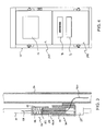
- FIG. 4 is a front view of another electronics rack with a multi-way opening door/panel/cover mounted thereon.
- FIG. 5 is an enlarged cross-sectional view of the electronically controlled hinge of FIG. 2 with multiple conductors for supplying a plurality of electronic signals.
- the present invention is directed to a door, panel or cover 10 for an electronics rack 12 that is mounted so as to permit multi-directional opening of the door, panel or cover (i.e., opening of the door/panel/cover in the left or right, up or down directions).
- a dual opening door is shown which is particularly useful for ganged racks, i.e., multiple side-by-side racks, that at times require accessing adjacent racks simultaneously.
- the present invention permits such access without the need for removing the doors.
- the door 10 is mounted to the rack 12 through a plurality of hinges 14 that are attached to the door and a vertical post 16 of the rack 12 . As shown, there are hinges 14 on both lateral sides of the door 10 .
- Each hinge 14 is electronically controlled such that the hinge pin can be engaged or disengaged from hinge cup.
- the electronically controlled hinge 14 includes a solenoid controlled hinge pin assembly 20 and a hinge cup 22 .
- the hinge pin assembly 20 includes a pin housing 24 within which is reciprocally mounted a hinge pin 26 .
- a solenoid 28 controls the reciprocation of the hinge pin 26 into and out of the housing 24 .
- the hinge cup 22 includes a recess 23 into which the hinge pin 26 can slide when it is extended from the housing 24 .
- a controller 30 controls the actuation of the solenoids 28 .
- the controller 30 could be an electronic panel mounted on the rack that is wired to the solenoids 28 .
- the controller 30 is preferably configured to provide at least the following control selections: (i) “open left side” (which sends commands to the hinges 14 on the left side of the door to cause the solenoids 28 to retract the hinge pins 26 ); (ii) “open right side” (which sends commands to the hinges 14 on the right side of the door to cause the solenoids 28 to retract the hinge pins 26 ); and (iii) “remove door” (which sends commands to all the hinges 14 to cause the solenoids 28 to retract the hinge pins 26 ).
- the controller 30 may in addition or in the alternative include a computer application 40 that can be stored on and run from a remote processing device, such as a laptop or a mobile smart phone.
- the computer application 40 would provide the ability to send commands to the hinges 14 as set forth above (e.g., open left side, open right side, remove door).
- the remote device if the remote device is not hard wired to the controller 30 , the remote device includes a transmitter for sending the signals 42 (such as by wireless (WiFi) signals) and the controller 30 would include a receiver (such as a WiFi dongle) for receiving the signals.
- the rack may be an intelligent smart rack that includes suitable electrical communication components that permits wired communications through the internet.
- One suitable electronic control is the RackLink® control system available from Middle Atlantic Products, Inc., Fairfield, N.J.
- the present invention contemplates the use of a novel manner of supplying electrical signals, such as power, data or control signals, to the door.
- a wire lead 50 extends from a power source P to the hinge pin 26 .
- the hinge pin 26 is preferably made from a conductive material or, more preferably, includes a conductive trace or wire 26 A that extends from the wire lead 50 to the tip 52 of the pin 26 .
- a conductive spring 54 is located within the recess 23 and is electrically connected to a wire lead 56 that extends to the electrically powered component on the door.
- a conductive circuit is provided between the power source and the electrical/data component through the electrically controlled hinge pin 26 that supplies the additional control signal(s).
- the hinge pin assembly 20 is disengaged, the pin 26 is retracted out of contact with the spring 54 , thus stopping power supply to the door. If the electrical signal needs to be sent to the door only when it is closed, then only a signal hinge 14 needs to provide the electrical signal since it is not necessary to supply power when the door is open. If, however, it is desired that the electrical signals are continuous, then at least one hinge 14 on each side of the door 10 in the dual-directional opening door embodiment is configured to pass electrical signals to the door from the rack 12 .
- the controller 30 would include programming to determine which of the two electronic signal transmitting hinges (e.g., the left or right hinge) should supply the signal to the door 10 .
- controller receives a command to unlock a hinge 14 that is transmitting electronic signals, for example, power, to the door, the controller redirects the electronic signals to the hinge that remains engaged before disengaging the hinge to be unlocked.
- the system could be configured to supply the power to hinges on both sides and a switch (not shown) included on the door to change from one lead 56 to the other when power is no longer supplied on one lead 56 .
- the hinges may be used for supplying different signals for different tasks.
- the lower hinges may be used for supplying power to an electrical component on the door
- the upper hinges may be used for supplying power to a second electrical component or, more preferably, for supplying data or control signals to an electrical component on the door, such as a display.
- a single hinge can be used to transmit multiple electronic signals (such as power, data and control signals).
- the hinge pin 26 ′ in addition to the conductive tip 52 , the hinge pin 26 ′ includes separate bands of conductive material 60 separated by insulators 62 . Each conductive band 60 and the tip 52 would be attached to a separate electronic signal supply line (e.g., power L 1 , data L 2 , control signals L 3 ).
- the hinge cup 22 would have conductive contacts or springs 64 at distinct locations on the inside of the cup which contact the appropriate conductive band 60 . Each spring 54 , 64 would be attached to a separate line 56 , 66 to receive the electronic signal transmitted through the respective spring 54 , 64 and connect to the appropriate component.
- the rack there was only a single door 10 on the rack. However, it is contemplated that there may be two or more doors on the rack. For example, as shown in FIG. 4 , there may be two doors 10 A, 10 B, each covering a portion of the rack 10 .
- the present invention can be applied to covers mounted on the top, sides or back of the rack, thus permitting multiple controlled entry points.
- instructions could be sent to a display screen on the door of a rack providing a service technician with detailed instruction for servicing or configuring a the particular rack.
Landscapes
- Engineering & Computer Science (AREA)
- Microelectronics & Electronic Packaging (AREA)
- Computer Hardware Design (AREA)
- General Engineering & Computer Science (AREA)
- Casings For Electric Apparatus (AREA)
Abstract
Description
Claims (10)
Priority Applications (1)
| Application Number | Priority Date | Filing Date | Title |
|---|---|---|---|
| US15/977,783 US10172256B2 (en) | 2017-06-02 | 2018-05-11 | Multi-way opening panel for an electronics rack with electronically controlled hinge |
Applications Claiming Priority (2)
| Application Number | Priority Date | Filing Date | Title |
|---|---|---|---|
| US201762514129P | 2017-06-02 | 2017-06-02 | |
| US15/977,783 US10172256B2 (en) | 2017-06-02 | 2018-05-11 | Multi-way opening panel for an electronics rack with electronically controlled hinge |
Publications (2)
| Publication Number | Publication Date |
|---|---|
| US20180352674A1 US20180352674A1 (en) | 2018-12-06 |
| US10172256B2 true US10172256B2 (en) | 2019-01-01 |
Family
ID=64458432
Family Applications (1)
| Application Number | Title | Priority Date | Filing Date |
|---|---|---|---|
| US15/977,783 Active US10172256B2 (en) | 2017-06-02 | 2018-05-11 | Multi-way opening panel for an electronics rack with electronically controlled hinge |
Country Status (1)
| Country | Link |
|---|---|
| US (1) | US10172256B2 (en) |
Cited By (1)
| Publication number | Priority date | Publication date | Assignee | Title |
|---|---|---|---|---|
| US11350534B1 (en) * | 2020-12-10 | 2022-05-31 | Super Micro Computer, Inc. | Telecommunication cabinet with replaceable cabinet door module |
Families Citing this family (4)
| Publication number | Priority date | Publication date | Assignee | Title |
|---|---|---|---|---|
| USD904327S1 (en) * | 2018-04-10 | 2020-12-08 | Fmr Llc | Freestanding blanking panel |
| US20220066503A1 (en) * | 2019-04-30 | 2022-03-03 | Hewlett-Packard Development Company, L.P. | Translating members |
| CN110740395B (en) * | 2019-10-29 | 2020-10-27 | 台州椒江中含乐器科技有限公司 | Sound power amplifier cabinet capable of accommodating microphone |
| CN113294962B (en) * | 2020-02-21 | 2022-10-28 | 青岛海尔电冰箱有限公司 | Refrigerator and door state detection method thereof |
Citations (6)
| Publication number | Priority date | Publication date | Assignee | Title |
|---|---|---|---|---|
| US5001602A (en) * | 1988-11-28 | 1991-03-19 | Reliance Comm/Tec Corporation | Network interface cabinet for large pair count telephone terminations |
| US6445585B1 (en) * | 2000-07-27 | 2002-09-03 | Eaton Corporation | Door-in-a-door device access module |
| US7518876B1 (en) * | 2008-03-11 | 2009-04-14 | International Business Machines Corporation | Retractable operator control panel with universal hinge design and dual orientation features |
| US20090277661A1 (en) * | 2006-12-12 | 2009-11-12 | Michael Schell | Control box arrangement |
| US8503182B2 (en) * | 2010-03-11 | 2013-08-06 | Bretford Manufacturing, Inc. | Electronic device storage tray |
| US20160192529A1 (en) * | 2014-12-29 | 2016-06-30 | International Business Machines Corporation | Modular elements employing latches with flexure bearings |
-
2018
- 2018-05-11 US US15/977,783 patent/US10172256B2/en active Active
Patent Citations (7)
| Publication number | Priority date | Publication date | Assignee | Title |
|---|---|---|---|---|
| US5001602A (en) * | 1988-11-28 | 1991-03-19 | Reliance Comm/Tec Corporation | Network interface cabinet for large pair count telephone terminations |
| US6445585B1 (en) * | 2000-07-27 | 2002-09-03 | Eaton Corporation | Door-in-a-door device access module |
| US20090277661A1 (en) * | 2006-12-12 | 2009-11-12 | Michael Schell | Control box arrangement |
| US8283576B2 (en) * | 2006-12-12 | 2012-10-09 | Rittal Gmbh & Co. Kg | Hinges for control box enclosure |
| US7518876B1 (en) * | 2008-03-11 | 2009-04-14 | International Business Machines Corporation | Retractable operator control panel with universal hinge design and dual orientation features |
| US8503182B2 (en) * | 2010-03-11 | 2013-08-06 | Bretford Manufacturing, Inc. | Electronic device storage tray |
| US20160192529A1 (en) * | 2014-12-29 | 2016-06-30 | International Business Machines Corporation | Modular elements employing latches with flexure bearings |
Cited By (2)
| Publication number | Priority date | Publication date | Assignee | Title |
|---|---|---|---|---|
| US11350534B1 (en) * | 2020-12-10 | 2022-05-31 | Super Micro Computer, Inc. | Telecommunication cabinet with replaceable cabinet door module |
| US20220192040A1 (en) * | 2020-12-10 | 2022-06-16 | Super Micro Computer, Inc. | Telecommunication cabinet with replaceable cabinet door module |
Also Published As
| Publication number | Publication date |
|---|---|
| US20180352674A1 (en) | 2018-12-06 |
Similar Documents
| Publication | Publication Date | Title |
|---|---|---|
| US10172256B2 (en) | Multi-way opening panel for an electronics rack with electronically controlled hinge | |
| US9955548B2 (en) | Wireless control device | |
| US20170064850A1 (en) | Modular Device Control Unit | |
| US20130063382A1 (en) | Multi-Position Under-Cabinet Mounted Control System for a Portable Touch Screen Device | |
| US20170102493A1 (en) | Wireless control device having a faceplate with illuminated indicia | |
| US9857841B2 (en) | Modular gang box docking system for computing devices | |
| JP2015526941A (en) | Electric furniture drive | |
| US10404017B2 (en) | Plug load receptacle | |
| US9559474B2 (en) | Track transmission system and track transmission device thereof | |
| US20190273386A1 (en) | Infrared intelligent control wireless charging bracket | |
| EP3104075B1 (en) | Electromechanical adapter for electrified tracks | |
| US20180124930A1 (en) | Interactive Cabinetry Door for Use with a Cabinet Base | |
| CN104852152B (en) | A kind of antenna and electronic equipment | |
| EP3285482A1 (en) | Television mainboard device and television system | |
| WO2015164412A1 (en) | Remote power management of an adapter | |
| US10122080B2 (en) | Supply cable, a driver arrangement with wireless control function and a control method | |
| EP3462677A1 (en) | Communication module for a household appliance | |
| CN107768916B (en) | Power cord and household appliance provided with same | |
| US5761042A (en) | Radio frequency compatible multi-board cluster | |
| EP3285483A1 (en) | Television mainboard device, television, and television system | |
| CN203405682U (en) | Intelligent home entertainment apparatus control device | |
| GB2510565A (en) | Switch or socket wall plate with integrated radio frequency antenna | |
| CN219107099U (en) | Wireless charging device and wireless charging equipment | |
| US9750115B2 (en) | Interface module for powering wireless user interface through light switch | |
| US20180061589A1 (en) | Bus type switch socket bracket |
Legal Events
| Date | Code | Title | Description |
|---|---|---|---|
| FEPP | Fee payment procedure |
Free format text: ENTITY STATUS SET TO UNDISCOUNTED (ORIGINAL EVENT CODE: BIG.); ENTITY STATUS OF PATENT OWNER: LARGE ENTITY |
|
| AS | Assignment |
Owner name: MIDDLE ATLANTIC PRODUCTS, INC., NEW JERSEY Free format text: ASSIGNMENT OF ASSIGNORS INTEREST;ASSIGNORS:WALSH, BRENDAN K.;CORBO, NICO;REEL/FRAME:047063/0692 Effective date: 20180927 |
|
| AS | Assignment |
Owner name: MIDDLE ATLANTIC PRODUCTS, INC., NEW JERSEY Free format text: ASSIGNMENT OF ASSIGNORS INTEREST;ASSIGNOR:GLENDMYER, ANDREW;REEL/FRAME:047550/0328 Effective date: 20170810 |
|
| STCF | Information on status: patent grant |
Free format text: PATENTED CASE |
|
| AS | Assignment |
Owner name: LEGRAND AV INC., NEW JERSEY Free format text: MERGER AND CHANGE OF NAME;ASSIGNORS:MIDDLE ATLANTIC PRODUCTS, INC.;MILESTONE AV TECHNOLOGIES INC.;REEL/FRAME:049922/0634 Effective date: 20181231 |
|
| MAFP | Maintenance fee payment |
Free format text: PAYMENT OF MAINTENANCE FEE, 4TH YEAR, LARGE ENTITY (ORIGINAL EVENT CODE: M1551); ENTITY STATUS OF PATENT OWNER: LARGE ENTITY Year of fee payment: 4 |