US10167891B1 - Self-reporting, grounded nut-clip - Google Patents
Self-reporting, grounded nut-clip Download PDFInfo
- Publication number
- US10167891B1 US10167891B1 US15/915,841 US201815915841A US10167891B1 US 10167891 B1 US10167891 B1 US 10167891B1 US 201815915841 A US201815915841 A US 201815915841A US 10167891 B1 US10167891 B1 US 10167891B1
- Authority
- US
- United States
- Prior art keywords
- clip
- reporting
- self
- nut
- grounded
- Prior art date
- Legal status (The legal status is an assumption and is not a legal conclusion. Google has not performed a legal analysis and makes no representation as to the accuracy of the status listed.)
- Active
Links
- 238000009434 installation Methods 0.000 claims abstract description 13
- 230000004913 activation Effects 0.000 claims abstract description 9
- 239000004020 conductor Substances 0.000 claims description 20
- 239000003973 paint Substances 0.000 claims description 13
- 238000000034 method Methods 0.000 claims description 12
- 230000000295 complement effect Effects 0.000 claims description 11
- 230000009471 action Effects 0.000 description 4
- 238000010586 diagram Methods 0.000 description 3
- 238000005516 engineering process Methods 0.000 description 3
- 230000008901 benefit Effects 0.000 description 2
- 239000000463 material Substances 0.000 description 2
- 238000007514 turning Methods 0.000 description 2
- 229910000639 Spring steel Inorganic materials 0.000 description 1
- 229910045601 alloy Inorganic materials 0.000 description 1
- 239000000956 alloy Substances 0.000 description 1
- 239000011248 coating agent Substances 0.000 description 1
- 238000000576 coating method Methods 0.000 description 1
- 210000005069 ears Anatomy 0.000 description 1
- 230000006872 improvement Effects 0.000 description 1
- 238000011900 installation process Methods 0.000 description 1
- 238000003754 machining Methods 0.000 description 1
- 238000004519 manufacturing process Methods 0.000 description 1
- 230000000873 masking effect Effects 0.000 description 1
- 239000007769 metal material Substances 0.000 description 1
- 238000012986 modification Methods 0.000 description 1
- 230000004048 modification Effects 0.000 description 1
- 238000010422 painting Methods 0.000 description 1
- 230000000149 penetrating effect Effects 0.000 description 1
- 238000003860 storage Methods 0.000 description 1
Images


Classifications
-
- F—MECHANICAL ENGINEERING; LIGHTING; HEATING; WEAPONS; BLASTING
- F16—ENGINEERING ELEMENTS AND UNITS; GENERAL MEASURES FOR PRODUCING AND MAINTAINING EFFECTIVE FUNCTIONING OF MACHINES OR INSTALLATIONS; THERMAL INSULATION IN GENERAL
- F16B—DEVICES FOR FASTENING OR SECURING CONSTRUCTIONAL ELEMENTS OR MACHINE PARTS TOGETHER, e.g. NAILS, BOLTS, CIRCLIPS, CLAMPS, CLIPS OR WEDGES; JOINTS OR JOINTING
- F16B39/00—Locking of screws, bolts or nuts
- F16B39/02—Locking of screws, bolts or nuts in which the locking takes place after screwing down
- F16B39/10—Locking of screws, bolts or nuts in which the locking takes place after screwing down by a plate, spring, wire or ring immovable with regard to the bolt or object and mainly perpendicular to the axis of the bolt
-
- F—MECHANICAL ENGINEERING; LIGHTING; HEATING; WEAPONS; BLASTING
- F16—ENGINEERING ELEMENTS AND UNITS; GENERAL MEASURES FOR PRODUCING AND MAINTAINING EFFECTIVE FUNCTIONING OF MACHINES OR INSTALLATIONS; THERMAL INSULATION IN GENERAL
- F16B—DEVICES FOR FASTENING OR SECURING CONSTRUCTIONAL ELEMENTS OR MACHINE PARTS TOGETHER, e.g. NAILS, BOLTS, CIRCLIPS, CLAMPS, CLIPS OR WEDGES; JOINTS OR JOINTING
- F16B33/00—Features common to bolt and nut
- F16B33/004—Sealing; Insulation
-
- F—MECHANICAL ENGINEERING; LIGHTING; HEATING; WEAPONS; BLASTING
- F16—ENGINEERING ELEMENTS AND UNITS; GENERAL MEASURES FOR PRODUCING AND MAINTAINING EFFECTIVE FUNCTIONING OF MACHINES OR INSTALLATIONS; THERMAL INSULATION IN GENERAL
- F16B—DEVICES FOR FASTENING OR SECURING CONSTRUCTIONAL ELEMENTS OR MACHINE PARTS TOGETHER, e.g. NAILS, BOLTS, CIRCLIPS, CLAMPS, CLIPS OR WEDGES; JOINTS OR JOINTING
- F16B43/00—Washers or equivalent devices; Other devices for supporting bolt-heads or nuts
-
- F—MECHANICAL ENGINEERING; LIGHTING; HEATING; WEAPONS; BLASTING
- F16—ENGINEERING ELEMENTS AND UNITS; GENERAL MEASURES FOR PRODUCING AND MAINTAINING EFFECTIVE FUNCTIONING OF MACHINES OR INSTALLATIONS; THERMAL INSULATION IN GENERAL
- F16B—DEVICES FOR FASTENING OR SECURING CONSTRUCTIONAL ELEMENTS OR MACHINE PARTS TOGETHER, e.g. NAILS, BOLTS, CIRCLIPS, CLAMPS, CLIPS OR WEDGES; JOINTS OR JOINTING
- F16B5/00—Joining sheets or plates, e.g. panels, to one another or to strips or bars parallel to them
- F16B5/06—Joining sheets or plates, e.g. panels, to one another or to strips or bars parallel to them by means of clamps or clips
- F16B5/0607—Joining sheets or plates, e.g. panels, to one another or to strips or bars parallel to them by means of clamps or clips joining sheets or plates to each other
- F16B5/0621—Joining sheets or plates, e.g. panels, to one another or to strips or bars parallel to them by means of clamps or clips joining sheets or plates to each other in parallel relationship
- F16B5/0635—Joining sheets or plates, e.g. panels, to one another or to strips or bars parallel to them by means of clamps or clips joining sheets or plates to each other in parallel relationship fastened over the edges of the sheets or plates
-
- H—ELECTRICITY
- H05—ELECTRIC TECHNIQUES NOT OTHERWISE PROVIDED FOR
- H05K—PRINTED CIRCUITS; CASINGS OR CONSTRUCTIONAL DETAILS OF ELECTRIC APPARATUS; MANUFACTURE OF ASSEMBLAGES OF ELECTRICAL COMPONENTS
- H05K7/00—Constructional details common to different types of electric apparatus
- H05K7/14—Mounting supporting structure in casing or on frame or rack
- H05K7/1485—Servers; Data center rooms, e.g. 19-inch computer racks
- H05K7/1488—Cabinets therefor, e.g. chassis or racks or mechanical interfaces between blades and support structures
-
- H—ELECTRICITY
- H05—ELECTRIC TECHNIQUES NOT OTHERWISE PROVIDED FOR
- H05K—PRINTED CIRCUITS; CASINGS OR CONSTRUCTIONAL DETAILS OF ELECTRIC APPARATUS; MANUFACTURE OF ASSEMBLAGES OF ELECTRICAL COMPONENTS
- H05K7/00—Constructional details common to different types of electric apparatus
- H05K7/18—Construction of rack or frame
-
- F—MECHANICAL ENGINEERING; LIGHTING; HEATING; WEAPONS; BLASTING
- F16—ENGINEERING ELEMENTS AND UNITS; GENERAL MEASURES FOR PRODUCING AND MAINTAINING EFFECTIVE FUNCTIONING OF MACHINES OR INSTALLATIONS; THERMAL INSULATION IN GENERAL
- F16B—DEVICES FOR FASTENING OR SECURING CONSTRUCTIONAL ELEMENTS OR MACHINE PARTS TOGETHER, e.g. NAILS, BOLTS, CIRCLIPS, CLAMPS, CLIPS OR WEDGES; JOINTS OR JOINTING
- F16B2200/00—Constructional details of connections not covered for in other groups of this subclass
- F16B2200/93—Fastener comprising feature for establishing a good electrical connection, e.g. electrostatic discharge or insulation feature
-
- F—MECHANICAL ENGINEERING; LIGHTING; HEATING; WEAPONS; BLASTING
- F16—ENGINEERING ELEMENTS AND UNITS; GENERAL MEASURES FOR PRODUCING AND MAINTAINING EFFECTIVE FUNCTIONING OF MACHINES OR INSTALLATIONS; THERMAL INSULATION IN GENERAL
- F16B—DEVICES FOR FASTENING OR SECURING CONSTRUCTIONAL ELEMENTS OR MACHINE PARTS TOGETHER, e.g. NAILS, BOLTS, CIRCLIPS, CLAMPS, CLIPS OR WEDGES; JOINTS OR JOINTING
- F16B37/00—Nuts or like thread-engaging members
- F16B37/04—Devices for fastening nuts to surfaces, e.g. sheets, plates
- F16B37/041—Releasable devices
Definitions
- the present invention generally relates to nut-clips, and more specifically, to a self-reporting, grounded nut-clip.
- a rack is a frame or enclosure that is configured for mounting multiple electronic equipment modules inside of an interior.
- the electronic equipment modules can include servers, telecommunication relays, etc.
- Equipment designed to be placed in a rack is typically described as rack mounted, a rack mounted instrument, a rack mounted system, a rack mount chassis, a sub-rack, rack mountable or occasionally as simply shelf equipment.
- Embodiments of the present invention are directed to a self-reporting, grounded nut-clip.
- a non-limiting example of the self-reporting, grounded nut-clip includes a support body.
- the support body includes first and second bends defining first, second and third support sections interleaved with the first and second bends.
- the first and third support sections define first and second apertures, respectively, and the second support section is interposed between the first and third support sections.
- the non-limiting example of the self-reporting, grounded nut-clip further includes a fastening element receiving member disposed on the first support section at the first aperture, a star washer, and an indicator.
- the star washer is disposed on the third support section at a location of the second aperture.
- the indicator is coupled to the third support section and is configured for automatic activation upon complete nut-clip installation.
- Embodiments of the present invention are directed to a structural assembly.
- a non-limiting example of the structural assembly includes first and second structures having first and second flanges, respectively, the first and second flanges defining first and second through-holes, respectively.
- the first and second structures each include electrically conductive materials and paint covering the electrically conductive materials proximate to the first and second through-holes.
- the first and second structures are each disposable with the first and second through-holes aligned.
- the non-limiting example of the structural assembly includes a self-reporting, grounded nut-clip defining apertures disposable in alignment with the first and second through-holes.
- the self-reporting, grounded nut-clip includes a star washer and an indicator configured for automatic activation upon complete nut-clip installation.
- the structural assembly further includes a fastening element configured for extension through the first and second through-holes and for engagement with the apertures to tighten the first and second flanges onto opposite sides of the star washer such that the opposite sides of the star washer electrically contact the conductive materials through the paint.
- Embodiments of the present invention are directed to a structural assembly method.
- a non-limiting example of the structural assembly method includes arranging first and second rack mount structures having first and second flanges, respectively, which define first and second through-holes, respectively, such that the first and second through-holes are aligned.
- the non-limiting example of the structural assembly method further includes disposing a self-reporting, grounded nut-clip including a star washer and an indicator configured for automatic activation upon complete nut-clip installation and defining apertures such that the apertures align with the first and second through-holes.
- the non-limiting example of the structural assembly method further includes engaging a fastening element with the apertures to tighten the first and second flanges onto opposite sides of the star washer such that the opposite sides of the star washer electrically contact first and second electrically conductive materials of the first and second rack mount structures, respectively, through paint overlying the first and second electrically conductive materials and continuing the engaging until the indicator automatically activates.
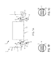
- FIG. 1A is a schematic, top-down view of a rack mount assembly according to embodiments of the invention.
- FIG. 1B is an enlarged view of the portion of FIG. 1A encircled by circle C 1 ;
- FIG. 1C is an enlarged view of the portion of FIG. 1A encircled by circle C 2 ;
- FIG. 2 is a schematic, front view of a self-reporting, grounded nut-clip according to embodiments of the invention
- FIG. 3 is a schematic, front view of a self-reporting, grounded nut-clip according to embodiments of the invention.
- FIG. 4 is a schematic, front view of a self-reporting, grounded nut-clip according to embodiments of the invention.
- FIG. 5 is an illustration of an installation process of the self-reporting grounded nut-clip of FIGS. 1A, 1B, 1C, 2, 3 and 4 ;
- FIG. 6 is a schematic, top-down view of a rack mount assembly according to further embodiments of the invention.
- FIG. 7 is a schematic illustration of an operation of an indicator of a self-reporting, grounded nut-clip according to embodiments of the invention.
- FIG. 8 is a flow diagram of a structural assembly method according to embodiments of the invention.
- rack systems can be made of generally very high value components and can be configured as storage racks, racks for mainframes, racks for computers, racks for security appliances, etc.
- IT information technology
- telecommunications equipment is stored in rack systems that are often subject to Electronics Industry Alliance Standard 310-D (or IEC 60297).
- the face (or ears) of rackable equipment is pushed up against and held to rails by screws through multiple hole locations.
- these rails were threaded at each hole location but this has changed over time due to the fact that rails need to be thicker to tap, which adds cost and weight, and the additional machining required increases manufacturing time.
- Multiple ad-hoc standards for the threading emerged (10-32, 12-23, M6, etc.) and this leads to incompatibilities between rack systems.
- one or more embodiments of the invention address the need for assembly certain structures together, for grounding those structures and for providing a visible indication of a good assembly.
- a structural assembly 10 is provided for use with multiple structural articles including, for example, rack mount systems and automobiles.
- the following description will generally relate to the structural assembly 10 being provided for use with rack mount systems but it is to be understood that this is merely exemplary and that other embodiments exist.
- the structural assembly 10 includes a first structure 11 and a second structure 12 .
- the first structure 11 can be provided as a rack enclosure 110 and includes opposite sidewalls 111 and a pair of first flanges 112 extending inwardly from forward-most edges of the opposite sidewalls 111 . Each of the first flanges 112 is formed to define first through-holes 113 .
- the first structure 11 can include various materials but particularly includes electrically conductive materials 114 and paint 115 covering the electrically conductive materials 114 at least at locations proximate to the first through-holes 113 (see FIG. 1B ).
- the second structure 12 can be provided as a rackable unit 120 and includes a pair of second flanges 121 extending outwardly from opposite sides of the rackable unit 120 . Each of the second flanges 121 is formed to define second through-holes 122 .
- the second structure 12 can include various materials but particularly includes electrically conductive materials 123 and paint 124 covering the electrically conductive materials 123 at least at locations proximate to the second through-holes 122 .
- the first structure 11 and the second structure 12 can each be disposed with the first through-holes 113 and the second through-holes 122 aligned with each other.
- the structural assembly 10 also includes a pair of self-reporting, grounded nut-clips 20 for respective association each of the aligned sets of first and second through-holes 113 and 122 and a pair of fastening elements 30 for respective association with each of the self-reporting, grounded nut-clips 20 . That is, a self-reporting, grounded nut-clip 20 can be provided for the first and second through-holes 113 and 122 at one side of the rackable unit 120 and an additional self-reporting, grounded nut-clip 20 can be provided for the first and second through-holes 113 and 122 at the opposite side of the rackable unit 120 .
- each self-reporting, grounded nut-clip 20 can be formed of plastic and/or metallic materials and can include a support body 21 , a fastening element receiving member 22 (see FIG. 1 ), a star washer 23 and an indicator 24 .
- the support body 21 includes first and second bends 210 and 211 that define and delimit first, second and third support sections 212 , 213 and 214 , which are respectively interleaved with the first and second bends 210 and 211 .
- the first support section 212 is formed to define a first aperture 215 .
- the third support section 214 is formed to define a second aperture 216 .
- the second support section 213 acts as a spine and is interposed between the first support section 212 and the third support section 214 .
- the fastening element receiving member 22 is disposed on the first support section 212 at, near or about the first aperture 215 .
- the star washer 23 is disposed on the third support section 214 at, near or about a location of the second aperture 216 .
- the indicator 24 is coupled to a top (see FIGS. 2 and 3 ) or a side (see FIG. 4 ) of the third support section 214 and is configured for automatic activation to be visible to an operator upon complete nut-clip installation.
- the star washer 23 can include a ring-shaped hub 230 and spiked spokes 231 extending radially outwardly from the ring-shaped hub 230 .
- Each of the spiked spokes 231 includes a pair of opposing axial spikes 232 that extend out of the plane of the ring-shaped hub 230 and the spiked spokes 231 in opposite axial directions.
- each self-reporting, grounded nut-clip 20 can include internal fixture tabs 25 .
- the first and second through-holes 113 and 122 are angular or rectangular. In these cases, each self-reporting, grounded nut-clip 20 can include external fixture tabs 26 .
- the fastening element receiving member 22 can be provided with a threaded interior that can engage with a threaded exterior of a corresponding one of the fastening elements 30 (the ring-shaped hub 230 of the star washer 23 can also be provided with a threaded interior that can engage with the threaded exterior of the corresponding one of the fastening elements 30 ).
- the corresponding one of the fastening elements 30 is extendable through the first and second through-holes 113 and 122 and is configured for engagement with the apertures first and second apertures 215 and 216 .
- Such extension and engagement result in the first and second flanges 112 and 121 tightening onto opposite sides of the star washer 23 as the fastening elements 30 are rotated about their respective longitudinal axes.
- the timing of the self-reporting, grounded nut-clip 20 can be configured such that the tightening of the first and second flanges 112 and 121 onto the opposite sides of the star washer 23 does not activate the indicator 24 until the opposing axial spikes 232 penetrate through the paint 115 and 124 to electrically contact the conductive materials 114 and 123 and to thereby ground the structural assembly 10 . Therefore, the indicator 24 effectively operates as an indicator that is visible to the operator that the structural assembly 10 has been properly grounded.
- At least the second bend 211 can be plural in number with the plural second bends 211 arranged as a sequence of plural second bends 211 at varying distances from the first bend 210 .
- the first and third support sections 212 and 214 are substantially parallel (see, e.g., FIG. 1 )
- a distance between the first and third support sections 212 and 214 is defined based on which of the plural second bends 211 is employed to wrap around the first or second flange 112 or 121 .
- each self-reporting, grounded nut-clip 20 is usable with first flanges 112 1,2 of varying thicknesses.
- Each self-reporting, grounded nut-clip 20 is initially provided as a substantially straight feature with a first bend 210 and plural second bends 211 available but not formed into angles.
- the first bend 210 is formed into a right angle, for example, that will align with a first edge of the first and second flanges 112 1,2 .
- the second bend 211 is formed thereafter as a right angle that will align with a second edge of the first flange 112 1 at a distance from the first bend 210 which is in accordance with the thickness of the first flange 112 1 .
- the second bend 211 is formed as a right angle that will align with a second edge of the second flange 112 2 at a distance from the first bend 210 which is in accordance with the thickness of the second flange 112 2 .
- the support body 21 can further include third and fourth bends 601 and 602 defining fourth and fifth support sections 603 and 604 interleaved with the third and fourth bends 601 and 602 .
- the fifth support section 604 is formed to define a third aperture 605 and the fourth support section is interposed between the third support section 214 and the fifth support section 604 .
- An additional star washer 606 is disposed on the fifth support section 604 at a location of the third aperture 605 .
- the spiked spokes of the additional star washer 606 penetrate the paint 124 to electrically contact the electrically conductive materials 123 on an exterior of the second flanges 121 to provide a redundant grounding feature structural assembly 10 .
- the indicator 24 can include complementary bezel surfaces 241 and 242 .
- the complementary bezel surfaces 241 and 242 Prior to installation of the self-reporting, grounded nut-clip 20 , the complementary bezel surfaces 241 and 242 are separated from one another. Subsequently, during installation of the self-reporting, grounded nut-clip 20 , the complementary bezel surfaces 241 and 242 are forced together to thereby automatically activate the indicator 24 .
- the structural assembly includes arranging first and second structures having first and second flanges, respectively, which define first and second through-holes, respectively, such that the first and second through-holes are aligned (block 801 ).
- the structural assembly method further includes disposing a self-reporting, grounded nut-clip that includes a star washer and an indicator configured for automatic activation upon complete nut-clip installation and defining apertures such that the apertures align with the first and second through-holes (block 802 ).
- the structural assembly method includes engaging a fastening element with the apertures to tighten the first and second flanges onto opposite sides of the star washer such that the opposite sides of the star washer electrically contact first and second electrically conductive materials of the first and second rack mount structures, respectively, through paint overlying the first and second electrically conductive materials (block 803 ) and continuing the engaging until the indicator automatically activates (block 804 ).
- the structural assembly method also includes grinding a bezel onto complementary edges of the star washer and a local nut-clip component (block 805 ) and separating the complementary edges such that the complementary edges are forced together during the nut-clip installation (block 806 ).
- the description provided above relates to a self-reporting, grounded nut-clip that serves to ground a structural assembly to which it is attached and provides a visible indication to an operator that it has been completely installed.
Abstract
A self-reporting, grounded nut-clip is provided. The self-reporting, grounded nut-clip includes a support body. The support body includes first and second bends defining first, second and third support sections interleaved with the first and second bends. The first and third support sections define first and second apertures, respectively, and the second support section is interposed between the first and third support sections. The self-reporting, grounded nut-clip further includes a fastening element receiving member disposed on the first support section at the first aperture, a star washer, and an indicator. The star washer is disposed on the third support section at a location of the second aperture. The indicator is coupled to the third support section and is configured for automatic activation upon complete nut-clip installation.
Description
The present invention generally relates to nut-clips, and more specifically, to a self-reporting, grounded nut-clip.
A rack is a frame or enclosure that is configured for mounting multiple electronic equipment modules inside of an interior. The electronic equipment modules can include servers, telecommunication relays, etc. Equipment designed to be placed in a rack is typically described as rack mounted, a rack mounted instrument, a rack mounted system, a rack mount chassis, a sub-rack, rack mountable or occasionally as simply shelf equipment.
Embodiments of the present invention are directed to a self-reporting, grounded nut-clip. A non-limiting example of the self-reporting, grounded nut-clip includes a support body. The support body includes first and second bends defining first, second and third support sections interleaved with the first and second bends. The first and third support sections define first and second apertures, respectively, and the second support section is interposed between the first and third support sections. The non-limiting example of the self-reporting, grounded nut-clip further includes a fastening element receiving member disposed on the first support section at the first aperture, a star washer, and an indicator. The star washer is disposed on the third support section at a location of the second aperture. The indicator is coupled to the third support section and is configured for automatic activation upon complete nut-clip installation.
Embodiments of the present invention are directed to a structural assembly. A non-limiting example of the structural assembly includes first and second structures having first and second flanges, respectively, the first and second flanges defining first and second through-holes, respectively. The first and second structures each include electrically conductive materials and paint covering the electrically conductive materials proximate to the first and second through-holes. The first and second structures are each disposable with the first and second through-holes aligned. The non-limiting example of the structural assembly includes a self-reporting, grounded nut-clip defining apertures disposable in alignment with the first and second through-holes. The self-reporting, grounded nut-clip includes a star washer and an indicator configured for automatic activation upon complete nut-clip installation. The structural assembly further includes a fastening element configured for extension through the first and second through-holes and for engagement with the apertures to tighten the first and second flanges onto opposite sides of the star washer such that the opposite sides of the star washer electrically contact the conductive materials through the paint.
Embodiments of the present invention are directed to a structural assembly method. A non-limiting example of the structural assembly method includes arranging first and second rack mount structures having first and second flanges, respectively, which define first and second through-holes, respectively, such that the first and second through-holes are aligned. The non-limiting example of the structural assembly method further includes disposing a self-reporting, grounded nut-clip including a star washer and an indicator configured for automatic activation upon complete nut-clip installation and defining apertures such that the apertures align with the first and second through-holes. In addition, the non-limiting example of the structural assembly method further includes engaging a fastening element with the apertures to tighten the first and second flanges onto opposite sides of the star washer such that the opposite sides of the star washer electrically contact first and second electrically conductive materials of the first and second rack mount structures, respectively, through paint overlying the first and second electrically conductive materials and continuing the engaging until the indicator automatically activates.
Additional technical features and benefits are realized through the techniques of the present invention. Embodiments and aspects of the invention are described in detail herein and are considered a part of the claimed subject matter. For a better understanding, refer to the detailed description and to the drawings.
The subject matter which is regarded as the invention is particularly pointed out and distinctly claimed in the claims at the conclusion of the specification. The forgoing and other features, and advantages of the invention are apparent from the following detailed description taken in conjunction with the accompanying drawings in which:
The diagrams depicted herein are illustrative. There can be many variations to the diagram or the operations described therein without departing from the spirit of the invention. For instance, the actions can be performed in a differing order or actions can be added, deleted or modified. Also, the term “coupled” and variations thereof describes having a communications path between two elements and does not imply a direct connection between the elements with no intervening elements/connections between them. All of these variations are considered a part of the specification.
In the accompanying figures and following detailed description of the disclosed embodiments, the various elements illustrated in the figures are provided with two or three digit reference numbers. With minor exceptions, the leftmost digit(s) of each reference number correspond to the figure in which its element is first illustrated.
Turning now to an overview of technologies that are more specifically relevant to aspects of the invention, rack systems can be made of generally very high value components and can be configured as storage racks, racks for mainframes, racks for computers, racks for security appliances, etc.
A large portion of information technology (IT) and telecommunications equipment is stored in rack systems that are often subject to Electronics Industry Alliance Standard 310-D (or IEC 60297). In such rack systems, the face (or ears) of rackable equipment is pushed up against and held to rails by screws through multiple hole locations. Originally, these rails were threaded at each hole location but this has changed over time due to the fact that rails need to be thicker to tap, which adds cost and weight, and the additional machining required increases manufacturing time. Multiple ad-hoc standards for the threading emerged (10-32, 12-23, M6, etc.) and this leads to incompatibilities between rack systems.
Rack systems then began to be designed with thinner metallic components (e.g., rails) and unthreaded holes that require clips. However, since rail thicknesses vary, since clips are often formed with spring steel and can be difficult to deal with and since clips typically must be bent past their elastic limits for removal, these solutions presented additional issues, such as cost pressures. Proper electrical bonding can be addressed by “masking off” the rails but this adds even further costs in setup before painting. Painted rails allow for cheaper alloys without anti-corrosive properties to be used.
In any case, while modern rack systems can be inexpensive and faster to produce than rack systems used to be, grounding suitability of rack systems has become degraded. As such, rackable equipment that must be redundantly grounded ends up being provided with ground straps, which have numerous problems of their own: customers forget to install them or do not know what they are for, customers (or trained installers) use them initially but untrained personnel later remove them and do not reinstall them properly, customers install them non-uniformly, leading to a confusing state where some equipment is grounded and other equipment is ungrounded and it is not always easy to confirm good contact without test equipment
Turning now to an overview of the aspects of the invention, one or more embodiments of the invention address the need for assembly certain structures together, for grounding those structures and for providing a visible indication of a good assembly.
With reference to FIGS. 1A, 1B, 1C, 2 and 3 , a structural assembly 10 is provided for use with multiple structural articles including, for example, rack mount systems and automobiles. The following description will generally relate to the structural assembly 10 being provided for use with rack mount systems but it is to be understood that this is merely exemplary and that other embodiments exist.
The structural assembly 10 includes a first structure 11 and a second structure 12. The first structure 11 can be provided as a rack enclosure 110 and includes opposite sidewalls 111 and a pair of first flanges 112 extending inwardly from forward-most edges of the opposite sidewalls 111. Each of the first flanges 112 is formed to define first through-holes 113. The first structure 11 can include various materials but particularly includes electrically conductive materials 114 and paint 115 covering the electrically conductive materials 114 at least at locations proximate to the first through-holes 113 (see FIG. 1B ). The second structure 12 can be provided as a rackable unit 120 and includes a pair of second flanges 121 extending outwardly from opposite sides of the rackable unit 120. Each of the second flanges 121 is formed to define second through-holes 122. The second structure 12 can include various materials but particularly includes electrically conductive materials 123 and paint 124 covering the electrically conductive materials 123 at least at locations proximate to the second through-holes 122.
The first structure 11 and the second structure 12 can each be disposed with the first through-holes 113 and the second through-holes 122 aligned with each other.
The structural assembly 10 also includes a pair of self-reporting, grounded nut-clips 20 for respective association each of the aligned sets of first and second through- holes 113 and 122 and a pair of fastening elements 30 for respective association with each of the self-reporting, grounded nut-clips 20. That is, a self-reporting, grounded nut-clip 20 can be provided for the first and second through- holes 113 and 122 at one side of the rackable unit 120 and an additional self-reporting, grounded nut-clip 20 can be provided for the first and second through- holes 113 and 122 at the opposite side of the rackable unit 120.
With continued reference to FIGS. 2 and 3 and with additional reference to FIG. 4 , each self-reporting, grounded nut-clip 20 can be formed of plastic and/or metallic materials and can include a support body 21, a fastening element receiving member 22 (see FIG. 1 ), a star washer 23 and an indicator 24. The support body 21 includes first and second bends 210 and 211 that define and delimit first, second and third support sections 212, 213 and 214, which are respectively interleaved with the first and second bends 210 and 211. The first support section 212 is formed to define a first aperture 215. The third support section 214 is formed to define a second aperture 216. The second support section 213 acts as a spine and is interposed between the first support section 212 and the third support section 214. The fastening element receiving member 22 is disposed on the first support section 212 at, near or about the first aperture 215. The star washer 23 is disposed on the third support section 214 at, near or about a location of the second aperture 216. The indicator 24 is coupled to a top (see FIGS. 2 and 3 ) or a side (see FIG. 4 ) of the third support section 214 and is configured for automatic activation to be visible to an operator upon complete nut-clip installation.
As shown in FIGS. 1 and 3 , the star washer 23 can include a ring-shaped hub 230 and spiked spokes 231 extending radially outwardly from the ring-shaped hub 230. Each of the spiked spokes 231 includes a pair of opposing axial spikes 232 that extend out of the plane of the ring-shaped hub 230 and the spiked spokes 231 in opposite axial directions.
In accordance with embodiments and, as shown in FIG. 2 , the first and second through- holes 113 and 122 are annular or circular. In these cases, each self-reporting, grounded nut-clip 20 can include internal fixture tabs 25. In accordance with embodiments and, as shown in FIG. 3 , the first and second through- holes 113 and 122 are angular or rectangular. In these cases, each self-reporting, grounded nut-clip 20 can include external fixture tabs 26.
In accordance with embodiments, the fastening element receiving member 22 can be provided with a threaded interior that can engage with a threaded exterior of a corresponding one of the fastening elements 30 (the ring-shaped hub 230 of the star washer 23 can also be provided with a threaded interior that can engage with the threaded exterior of the corresponding one of the fastening elements 30). Thus, where the self-reporting, grounded nut-clip 20 is disposed to register with the first and second flanges 112 and 121 such that the first and second apertures 215 and 216 align with the first and second through- holes 113 and 122, the corresponding one of the fastening elements 30 is extendable through the first and second through- holes 113 and 122 and is configured for engagement with the apertures first and second apertures 215 and 216. Such extension and engagement result in the first and second flanges 112 and 121 tightening onto opposite sides of the star washer 23 as the fastening elements 30 are rotated about their respective longitudinal axes. The opposing axial spikes 232 that extend out of the plane of the ring-shaped hub 230 and the spiked spokes 231 in opposite axial directions, therefore, penetrate through the paint 115 and 124 to electrically contact the conductive materials 114 and 123.
The action of tightening the first and second flanges 112 and 121 onto the opposite sides of the star washer 23 activates the indicator 24. Similarly, the action of the opposing axial spikes 232 penetrating through the paint 115 and 124 or other non-conductive coating to electrically contact the conductive materials 114 and 123 serves to ground the structural assembly 10. In accordance with embodiments, the timing of the self-reporting, grounded nut-clip 20 can be configured such that the tightening of the first and second flanges 112 and 121 onto the opposite sides of the star washer 23 does not activate the indicator 24 until the opposing axial spikes 232 penetrate through the paint 115 and 124 to electrically contact the conductive materials 114 and 123 and to thereby ground the structural assembly 10. Therefore, the indicator 24 effectively operates as an indicator that is visible to the operator that the structural assembly 10 has been properly grounded.
With reference to FIGS. 2-4 and 5 , at least the second bend 211 can be plural in number with the plural second bends 211 arranged as a sequence of plural second bends 211 at varying distances from the first bend 210. As such, where the first and third support sections 212 and 214 are substantially parallel (see, e.g., FIG. 1 ), a distance between the first and third support sections 212 and 214 is defined based on which of the plural second bends 211 is employed to wrap around the first or second flange 112 or 121.
As shown in FIG. 5 , each self-reporting, grounded nut-clip 20 is usable with first flanges 112 1,2 of varying thicknesses. Each self-reporting, grounded nut-clip 20 is initially provided as a substantially straight feature with a first bend 210 and plural second bends 211 available but not formed into angles. When the self-reporting, grounded nut-clip 20 is to be installed, the first bend 210 is formed into a right angle, for example, that will align with a first edge of the first and second flanges 112 1,2. The second bend 211 is formed thereafter as a right angle that will align with a second edge of the first flange 112 1 at a distance from the first bend 210 which is in accordance with the thickness of the first flange 112 1. Alternately, the second bend 211 is formed as a right angle that will align with a second edge of the second flange 112 2 at a distance from the first bend 210 which is in accordance with the thickness of the second flange 112 2.
Final configurations of each self-reporting, grounded nut-clip 20 following completion of the second bend 211 can be seen in the dashed details of the lower images of FIG. 5 and schematically in FIGS. 1 and 6 , for example.
With reference to FIG. 6 , the support body 21 can further include third and fourth bends 601 and 602 defining fourth and fifth support sections 603 and 604 interleaved with the third and fourth bends 601 and 602. The fifth support section 604 is formed to define a third aperture 605 and the fourth support section is interposed between the third support section 214 and the fifth support section 604. An additional star washer 606 is disposed on the fifth support section 604 at a location of the third aperture 605. Here, the spiked spokes of the additional star washer 606 penetrate the paint 124 to electrically contact the electrically conductive materials 123 on an exterior of the second flanges 121 to provide a redundant grounding feature structural assembly 10.
With reference to FIG. 7 , the indicator 24 can include complementary bezel surfaces 241 and 242. Prior to installation of the self-reporting, grounded nut-clip 20, the complementary bezel surfaces 241 and 242 are separated from one another. Subsequently, during installation of the self-reporting, grounded nut-clip 20, the complementary bezel surfaces 241 and 242 are forced together to thereby automatically activate the indicator 24.
With reference to FIG. 8 , a structural assembly method is provided for assembling the structural assembly 10 described herein. As shown in FIG. 8 , the structural assembly includes arranging first and second structures having first and second flanges, respectively, which define first and second through-holes, respectively, such that the first and second through-holes are aligned (block 801). The structural assembly method further includes disposing a self-reporting, grounded nut-clip that includes a star washer and an indicator configured for automatic activation upon complete nut-clip installation and defining apertures such that the apertures align with the first and second through-holes (block 802). In addition, the structural assembly method includes engaging a fastening element with the apertures to tighten the first and second flanges onto opposite sides of the star washer such that the opposite sides of the star washer electrically contact first and second electrically conductive materials of the first and second rack mount structures, respectively, through paint overlying the first and second electrically conductive materials (block 803) and continuing the engaging until the indicator automatically activates (block 804). In accordance with embodiments, the structural assembly method also includes grinding a bezel onto complementary edges of the star washer and a local nut-clip component (block 805) and separating the complementary edges such that the complementary edges are forced together during the nut-clip installation (block 806).
The description provided above relates to a self-reporting, grounded nut-clip that serves to ground a structural assembly to which it is attached and provides a visible indication to an operator that it has been completely installed.
The descriptions of the various embodiments of the present invention have been presented for purposes of illustration, but are not intended to be exhaustive or limited to the embodiments described. Many modifications and variations will be apparent to those of ordinary skill in the art without departing from the scope and spirit of the described embodiments. The terminology used herein was chosen to best explain the principles of the embodiments, the practical application or technical improvement over technologies found in the marketplace, or to enable others of ordinary skill in the art to understand the embodiments described herein.
Claims (20)
1. A self-reporting, grounded nut-clip, comprising:
a support body comprising first and second bends defining first, second and third support sections interleaved with the first and second bends,
the first and third support sections defining first and second apertures, respectively, and the second support section being interposed between the first and third support sections;
a fastening element receiving member disposed on the first support section at the first aperture;
a star washer disposed on the third support section at a location of the second aperture; and
an indicator coupled to the third support section and which is configured for automatic activation upon complete nut-clip installation.
2. The self-reporting, grounded nut-clip according to claim 1 , wherein the second bend is plural in number and arranged as a sequence of plural second bends at varying distances from the first bend.
3. The self-reporting, grounded nut-clip according to claim 1 , further comprising at least one of:
internal fixture tabs coupled to the first and third support sections; and
external fixture tabs coupled to the first and third support sections.
4. The self-reporting, grounded nut-clip according to claim 1 , wherein the star washer comprises:
a ring-shaped hub; and
spiked spokes extending radially outwardly from the ring-shaped hub.
5. The self-reporting, grounded nut-clip according to claim 4 , wherein the spiked spokes each comprise a pair of opposing axial spikes.
6. The self-reporting, grounded nut-clip according to claim 1 , wherein the indicator is coupled to one of a top and a side of the third support section.
7. The self-reporting, grounded nut-clip according to claim 1 , wherein the indicator comprises complementary bezel surfaces.
8. The self-reporting, grounded nut-clip according to claim 1 , wherein:
the support body further comprises third and fourth bends defining fourth and fifth support sections interleaved with the third and fourth bends,
the fifth support section defining a third aperture and the fourth support section being interposed between the third and fifth support sections; and
an additional star washer disposed on the fifth support section at a location of the third aperture.
9. A structural assembly, comprising:
first and second structures having first and second flanges, respectively, the first and second flanges defining first and second through-holes, respectively,
the first and second structures each comprising electrically conductive materials and paint covering the electrically conductive materials proximate to the first and second through-holes and each being disposable with the first and second through-holes aligned;
a self-reporting, grounded nut-clip defining apertures disposable in alignment with the first and second through-holes and comprising:
a star washer; and
an indicator configured for automatic activation upon complete nut-clip installation; and
a fastening element configured for extension through the first and second through-holes and for engagement with the apertures to tighten the first and second flanges onto opposite sides of the star washer such that the opposite sides of the star washer electrically contact the electrically conductive materials through the paint.
10. The structural assembly according to claim 9 , wherein:
the first structure comprises a rack enclosure and the first flange comprises a pair of inwardly extending first flanges, and
the second structure comprises a rackable unit and the second flange comprises a pair of outwardly extending second flanges.
11. The structural assembly according to claim 10 , wherein the self-reporting, grounded nut-clip and the fastening element are provided as respective pairs thereof.
12. The structural assembly according to claim 9 , wherein:
the first and second through-holes are annular and the self-reporting, grounded nut-clip comprises internal fixture tabs, or
the first and second through-holes are angular and the self-reporting, grounded nut-clip comprises external fixture tabs.
13. The structural assembly according to claim 9 , wherein the self-reporting, grounded nut-clip, comprises:
a support body comprising first and second bends defining first, second and third support sections interleaved with the first and second bends,
the first and third support sections defining the apertures as first and second apertures, respectively, and the second support section being interposed between the first and third support sections; and
a fastening element receiving member disposed on the first support section at the first aperture,
wherein the star washer is disposed on the third support section at a location of the second aperture and the indicator is coupled to the third support section.
14. The structural assembly according to claim 13 , wherein the second bend is plural in number and arranged as a sequence of plural second bends at varying distances from the first bend.
15. The structural assembly according to claim 13 , wherein the star washer comprises:
a ring-shaped hub; and
spiked spokes extending radially outwardly from the ring-shaped hub.
16. The structural assembly according to claim 15 , wherein the spiked spokes each comprise a pair of opposing axial spikes.
17. The structural assembly according to claim 13 , wherein the indicator is coupled to one of a top and a side of the third support section.
18. The structural assembly according to claim 13 , wherein the indicator comprises complementary bezel surfaces.
19. A structural assembly method, comprising:
arranging first and second structures having first and second flanges, respectively, which define first and second through-holes, respectively, such that the first and second through-holes are aligned;
disposing a self-reporting, grounded nut-clip comprising a star washer and an indicator configured for automatic activation upon complete nut-clip installation and defining apertures such that the apertures align with the first and second through-holes;
engaging a fastening element with the apertures to tighten the first and second flanges onto opposite sides of the star washer such that the opposite sides of the star washer electrically contact first and second electrically conductive materials of first and second rack mount structures, respectively, through paint overlying the first and second electrically conductive materials; and
continuing the engaging until the indicator automatically activates.
20. The structural assembly method according to claim 19 , further comprising:
grinding a bezel onto complementary edges of the star washer and a local nut-clip component; and
separating the complementary edges such that the complementary edges are forced together during the nut-clip installation.
Priority Applications (1)
| Application Number | Priority Date | Filing Date | Title |
|---|---|---|---|
| US15/915,841 US10167891B1 (en) | 2018-03-08 | 2018-03-08 | Self-reporting, grounded nut-clip |
Applications Claiming Priority (1)
| Application Number | Priority Date | Filing Date | Title |
|---|---|---|---|
| US15/915,841 US10167891B1 (en) | 2018-03-08 | 2018-03-08 | Self-reporting, grounded nut-clip |
Publications (1)
| Publication Number | Publication Date |
|---|---|
| US10167891B1 true US10167891B1 (en) | 2019-01-01 |
Family
ID=64739658
Family Applications (1)
| Application Number | Title | Priority Date | Filing Date |
|---|---|---|---|
| US15/915,841 Active US10167891B1 (en) | 2018-03-08 | 2018-03-08 | Self-reporting, grounded nut-clip |
Country Status (1)
| Country | Link |
|---|---|
| US (1) | US10167891B1 (en) |
Cited By (1)
| Publication number | Priority date | Publication date | Assignee | Title |
|---|---|---|---|---|
| US10932387B2 (en) * | 2018-05-25 | 2021-02-23 | Cisco Technology, Inc. | Quick release for online insertion and removal of a module in a distributed network system |
Citations (87)
| Publication number | Priority date | Publication date | Assignee | Title |
|---|---|---|---|---|
| US1359463A (en) * | 1915-06-10 | 1920-11-16 | pier-sen | |
| US2114067A (en) * | 1936-12-14 | 1938-04-12 | Galvin Mfg Corp | Indicating and control apparatus |
| US2219846A (en) * | 1939-03-15 | 1940-10-29 | Porcelain Products Inc | Tap connector |
| US2371592A (en) * | 1943-02-19 | 1945-03-13 | Folmer Graflex Corp | Automatic aerial camera |
| US2375059A (en) * | 1945-05-01 | Cardiometric apparatus | ||
| US2664475A (en) * | 1950-05-13 | 1953-12-29 | Harlin Brothers | Electrical receptacle, plug, and switch |
| US2911608A (en) * | 1956-03-13 | 1959-11-03 | Gen Motors Corp | Ground spring clip |
| GB982132A (en) | 1961-04-19 | 1965-02-03 | Multifastener Corp | Panel clip fastener with nut secured thereto |
| US3810069A (en) * | 1972-08-08 | 1974-05-07 | Hubbell Inc Harvey | Grounding clip for electrical fixtures |
| US3885847A (en) * | 1974-03-27 | 1975-05-27 | Sola Basic Ind Inc | Grounding clip with wrap-around tabs |
| US4256359A (en) * | 1979-05-25 | 1981-03-17 | Thomas & Betts Corporation | Termination connector |
| US4260849A (en) * | 1979-05-08 | 1981-04-07 | Telex Computer Products, Inc. | Low cost grounding hanger assembly |
| US4406505A (en) * | 1981-02-18 | 1983-09-27 | Daniel Woodhead, Inc. | Grounding clip for electrical fixtures |
| US4505010A (en) * | 1981-09-24 | 1985-03-19 | Arenhold K | Spring clip |
| US4526428A (en) * | 1984-03-30 | 1985-07-02 | Isaac Sachs | Multi-strand cable clamp with positive strand engagement |
| US4828504A (en) * | 1987-11-05 | 1989-05-09 | Franks George J Jr | Clamp |
| US4875876A (en) * | 1988-08-31 | 1989-10-24 | Thomas & Betts Corporation | Electrical connector for overlapped conductors |
| US4897005A (en) * | 1987-04-01 | 1990-01-30 | Buell Industries, Inc. | Gutted U-nut |
| US5094622A (en) * | 1991-06-17 | 1992-03-10 | Electric Motion Company, Incorporated | Cable rack bond clamp |
| US5154385A (en) * | 1991-04-08 | 1992-10-13 | George R. Todd | Support systems with improved channel nuts |
| US5160285A (en) * | 1990-10-10 | 1992-11-03 | C. A. Wieidmuller GmbH & Co. | Separable contact arrangement |
| US5207588A (en) * | 1980-02-02 | 1993-05-04 | Multifastener Corporation | Electrical grounding stud |
| US5253949A (en) * | 1992-07-21 | 1993-10-19 | Trw Inc. | Fail-safe universal joint connection |
| FR2697060A1 (en) | 1992-10-15 | 1994-04-22 | Rapid Sa | Clip nut esp. for electrical earth connections on panel - has hole on one side of folded U=piece for screw to pass through to thread opposite second hole with spikes on edge that indent panel |
| US5371819A (en) * | 1991-06-12 | 1994-12-06 | John Mezzalingua Assoc. Inc. | Fiber optic cable end connector with electrical grounding means |
| US5377558A (en) * | 1993-04-30 | 1995-01-03 | Harris; Dimitri | Protective device for covering brackets on motorcycle handlebars |
| US5442133A (en) * | 1993-09-08 | 1995-08-15 | Emhart Inc. | Grounding stud/nut |
| US5494456A (en) * | 1994-10-03 | 1996-02-27 | Methode Electronics, Inc. | Wire-trap connector with anti-overstress member |
| US5616036A (en) * | 1995-10-27 | 1997-04-01 | Thomas Polidori | Grounding clamp |
| US5688131A (en) * | 1996-09-03 | 1997-11-18 | Wirth Co Engineering, Inc. | Multi-use electrical connector |
| US5697797A (en) * | 1993-04-29 | 1997-12-16 | Rtb Ab | Device for grounded securing of an element at a hole in a metal plate |
| US5704805A (en) * | 1995-03-31 | 1998-01-06 | The Whitaker Corporation | Connector for connection to a rail |
| JP2767215B2 (en) | 1995-06-28 | 1998-06-18 | 中洲電機株式会社 | Ground terminal mounting member and ground terminal cover |
| GB2343726A (en) | 1998-11-13 | 2000-05-17 | Business Lines Limited | Indicating loosening of a nut or bolt |
| US6106310A (en) * | 1997-11-19 | 2000-08-22 | The Whitaker Corporation | Panel-grounding contact |
| US6209424B1 (en) * | 1994-03-15 | 2001-04-03 | Sicame Electrical Developments Ltd. | Clamping screws |
| US6345993B1 (en) * | 1999-06-03 | 2002-02-12 | Framatome Connectors International | Compact branch connector for at least one branch neutral cable into a main neutral cable and simultaneous grounding |
| USD459302S1 (en) * | 2001-07-12 | 2002-06-25 | Allied Bolt, Inc. | Grounding connector |
| US6431885B1 (en) * | 2000-06-27 | 2002-08-13 | X-Com Systems, Inc. | Electrical component grounding device, electrical system grounding and support apparatus, and antenna component grounding system |
| US20030169160A1 (en) * | 2000-07-12 | 2003-09-11 | Alejandro Rodriguez Barros | Rear-view mirror with multiple interchangeable signals for vehicles with two, three, four or more wheels |
| US6648698B1 (en) * | 2002-10-31 | 2003-11-18 | Illinois Tool Works Inc. | Grounding tab for a welding apparatus |
| US6652295B1 (en) * | 1997-02-28 | 2003-11-25 | Maris Anthony Glass | Ground bus for junction box |
| US6709280B1 (en) * | 2002-01-17 | 2004-03-23 | Arlington Industries, Inc. | Fitting with improved continuity |
| US6739880B2 (en) * | 2001-10-16 | 2004-05-25 | Molex Incorporated | Circuit board-to-board interconnection device |
| US6877996B1 (en) * | 2002-11-27 | 2005-04-12 | Senior Industries, Inc. | Grounding connector |
| US6957968B1 (en) * | 2002-01-17 | 2005-10-25 | Arlington Industries, Inc. | Snap engagement electrical fitting with flangeless body |
| US6991478B2 (en) * | 2004-01-08 | 2006-01-31 | Airbus France | Electrical connection device to make a metallisation point, support equipped with such a connection device and aircraft equipped with such a support |
| US6994586B2 (en) * | 2004-05-12 | 2006-02-07 | Funai Electric Co., Ltd. | Printed circuit board supporting structure |
| US7128583B2 (en) * | 2004-09-15 | 2006-10-31 | Benq Corporation | Grounding element |
| US7131867B1 (en) * | 2005-05-06 | 2006-11-07 | Pacific Aerospace & Electronics, Inc. | RF connectors having ground springs |
| US7154042B2 (en) * | 2004-09-13 | 2006-12-26 | Bridgeport Fittings, Inc. | Electrical connector with snap fit retainer ring constructed to enhance the connection of the connector to an electrical box |
| US20070093121A1 (en) * | 2005-10-24 | 2007-04-26 | Johannes Helmreich | Electrical Component, in Particular Relay Socket, Having Spring Clamps, and Method for the Manufacture Thereof |
| US7381105B2 (en) * | 2006-02-01 | 2008-06-03 | Sierra Madre Marketing Group | Electrical contact surface having numerous protrusions |
| US7387518B2 (en) * | 2005-12-23 | 2008-06-17 | M/A-Com, Inc. | Grounding attachment assembly |
| US7462042B2 (en) * | 2005-05-19 | 2008-12-09 | John Mezzalingua Associates, Inc. | Bonding block for coaxial cable |
| US7566250B1 (en) * | 2008-06-27 | 2009-07-28 | Tyco Electronics Corporation | Wire grounding assembly |
| US7670153B2 (en) * | 2007-09-10 | 2010-03-02 | Burndy Technology Llc | Electrical connector |
| US7686625B1 (en) * | 2008-11-07 | 2010-03-30 | Tyco Electronics Corporation | Grounding clip |
| US7753697B2 (en) * | 2007-09-03 | 2010-07-13 | Eurocopter | Electrical connection between first and second metal parts that are electrically insulated from each other |
| US7857269B2 (en) * | 2006-11-29 | 2010-12-28 | Pvt Solar, Inc. | Mounting assembly for arrays and other surface-mounted equipment |
| US7988464B2 (en) * | 2008-04-09 | 2011-08-02 | Panduit Corp. | Beam clamp |
| US8000111B2 (en) * | 2008-10-01 | 2011-08-16 | Inventec Corporation | Electronic device structure |
| US8013610B1 (en) * | 2006-12-21 | 2011-09-06 | Seektech, Inc. | High-Q self tuning locating transmitter |
| US8137116B2 (en) * | 2009-09-08 | 2012-03-20 | Autonetworks Technologies, Ltd. | Ground joint connector and wire harness including the same |
| US8152536B2 (en) * | 2009-03-10 | 2012-04-10 | Tyco Electronics Amp Gmbh | Connection device for connection to a solar module and solar module comprising such connection device |
| US8231317B2 (en) * | 2005-09-23 | 2012-07-31 | A. Raymond Et Cie | Fastening clamp |
| US8436243B2 (en) * | 2007-12-11 | 2013-05-07 | Airbus Operations (S.A.S.) | Anti-lightning system and aircraft comprising such a system |
| US8475185B2 (en) * | 2011-03-24 | 2013-07-02 | Solar Mounting Solutions, LLC | Solar panels grounding clip |
| CN203098530U (en) | 2013-03-06 | 2013-07-31 | 清源科技(厦门)股份有限公司 | Nut clamping piece capable of being installed quickly and bolt assembly |
| US8590223B2 (en) * | 2011-08-29 | 2013-11-26 | A. Raymond Et Cie | Solar panel assembly attachment apparatus |
| US20140065892A1 (en) * | 2012-09-05 | 2014-03-06 | Schneider Electric Industries Sas | Electrical connector and a connector assembly |
| US8777538B2 (en) * | 2012-09-10 | 2014-07-15 | Renewable Energy Holdings, Llc | Bonding fastener with environmental seals |
| US8806813B2 (en) * | 2006-08-31 | 2014-08-19 | Pvt Solar, Inc. | Technique for electrically bonding solar modules and mounting assemblies |
| US8888431B2 (en) * | 2013-03-15 | 2014-11-18 | Hubbell Incorporated | Adjustable bonding washer |
| US8918993B2 (en) * | 2005-12-15 | 2014-12-30 | The Boeing Company | Method for installing a ground stud in composite structures |
| US8955259B2 (en) * | 2011-06-09 | 2015-02-17 | A. Raymond & Cie | Solar panel attachment system for a roof |
| US20150104239A1 (en) | 2010-10-20 | 2015-04-16 | D Three Enterprises, Llc | Combination mounting and grounding clip |
| US20150144053A1 (en) * | 2013-11-22 | 2015-05-28 | Standex International Corporation | Pressure differential indicator |
| US9151315B2 (en) * | 2013-07-03 | 2015-10-06 | Sunrun South Llc | Devices, systems, and methods for securing a component to a surface |
| US9178288B2 (en) * | 2013-06-07 | 2015-11-03 | Apple Inc. | Spring plate for attaching bus bar to a printed circuit board |
| US20150349166A1 (en) | 2014-05-28 | 2015-12-03 | Sunedison Llc | Grounding clips and tabs for mounting components to solar modules |
| US20160268958A1 (en) * | 2015-03-11 | 2016-09-15 | Ecolibrium Solar, Inc. | Sloped Roof Solar Panel Mounting System |
| US9459135B2 (en) * | 2013-12-26 | 2016-10-04 | Aisin Seiki Kabushiki Kaisha | Cover for load detection sensor and load detection device |
| US20170074312A1 (en) | 2014-03-12 | 2017-03-16 | Rittal Gmbh & Co. Kg | Mounting system for mounting of equipment in particular electrical appliances |
| US9673602B2 (en) * | 2015-10-02 | 2017-06-06 | Rockwell Automation Technologies, Inc | System for isolating power conductors using cover assemblies |
| US9958586B2 (en) * | 2013-02-22 | 2018-05-01 | Geberit International Ag | Mounting device for a sanitary element |
| US10051767B2 (en) * | 2012-09-28 | 2018-08-14 | The Boeing Company | Method and apparatus for covering a fastener system |
-
2018
- 2018-03-08 US US15/915,841 patent/US10167891B1/en active Active
Patent Citations (93)
| Publication number | Priority date | Publication date | Assignee | Title |
|---|---|---|---|---|
| US2375059A (en) * | 1945-05-01 | Cardiometric apparatus | ||
| US1359463A (en) * | 1915-06-10 | 1920-11-16 | pier-sen | |
| US2114067A (en) * | 1936-12-14 | 1938-04-12 | Galvin Mfg Corp | Indicating and control apparatus |
| US2219846A (en) * | 1939-03-15 | 1940-10-29 | Porcelain Products Inc | Tap connector |
| US2371592A (en) * | 1943-02-19 | 1945-03-13 | Folmer Graflex Corp | Automatic aerial camera |
| US2664475A (en) * | 1950-05-13 | 1953-12-29 | Harlin Brothers | Electrical receptacle, plug, and switch |
| US2911608A (en) * | 1956-03-13 | 1959-11-03 | Gen Motors Corp | Ground spring clip |
| GB982132A (en) | 1961-04-19 | 1965-02-03 | Multifastener Corp | Panel clip fastener with nut secured thereto |
| US3810069A (en) * | 1972-08-08 | 1974-05-07 | Hubbell Inc Harvey | Grounding clip for electrical fixtures |
| US3885847A (en) * | 1974-03-27 | 1975-05-27 | Sola Basic Ind Inc | Grounding clip with wrap-around tabs |
| US4260849A (en) * | 1979-05-08 | 1981-04-07 | Telex Computer Products, Inc. | Low cost grounding hanger assembly |
| US4256359A (en) * | 1979-05-25 | 1981-03-17 | Thomas & Betts Corporation | Termination connector |
| US5207588A (en) * | 1980-02-02 | 1993-05-04 | Multifastener Corporation | Electrical grounding stud |
| US4406505A (en) * | 1981-02-18 | 1983-09-27 | Daniel Woodhead, Inc. | Grounding clip for electrical fixtures |
| US4505010A (en) * | 1981-09-24 | 1985-03-19 | Arenhold K | Spring clip |
| US4526428A (en) * | 1984-03-30 | 1985-07-02 | Isaac Sachs | Multi-strand cable clamp with positive strand engagement |
| US4897005A (en) * | 1987-04-01 | 1990-01-30 | Buell Industries, Inc. | Gutted U-nut |
| US4828504A (en) * | 1987-11-05 | 1989-05-09 | Franks George J Jr | Clamp |
| US4875876A (en) * | 1988-08-31 | 1989-10-24 | Thomas & Betts Corporation | Electrical connector for overlapped conductors |
| US5160285A (en) * | 1990-10-10 | 1992-11-03 | C. A. Wieidmuller GmbH & Co. | Separable contact arrangement |
| US5154385A (en) * | 1991-04-08 | 1992-10-13 | George R. Todd | Support systems with improved channel nuts |
| US5371819A (en) * | 1991-06-12 | 1994-12-06 | John Mezzalingua Assoc. Inc. | Fiber optic cable end connector with electrical grounding means |
| US5094622A (en) * | 1991-06-17 | 1992-03-10 | Electric Motion Company, Incorporated | Cable rack bond clamp |
| US5253949A (en) * | 1992-07-21 | 1993-10-19 | Trw Inc. | Fail-safe universal joint connection |
| FR2697060A1 (en) | 1992-10-15 | 1994-04-22 | Rapid Sa | Clip nut esp. for electrical earth connections on panel - has hole on one side of folded U=piece for screw to pass through to thread opposite second hole with spikes on edge that indent panel |
| US5697797A (en) * | 1993-04-29 | 1997-12-16 | Rtb Ab | Device for grounded securing of an element at a hole in a metal plate |
| US5377558A (en) * | 1993-04-30 | 1995-01-03 | Harris; Dimitri | Protective device for covering brackets on motorcycle handlebars |
| US5442133A (en) * | 1993-09-08 | 1995-08-15 | Emhart Inc. | Grounding stud/nut |
| US6209424B1 (en) * | 1994-03-15 | 2001-04-03 | Sicame Electrical Developments Ltd. | Clamping screws |
| US5494456A (en) * | 1994-10-03 | 1996-02-27 | Methode Electronics, Inc. | Wire-trap connector with anti-overstress member |
| US5704805A (en) * | 1995-03-31 | 1998-01-06 | The Whitaker Corporation | Connector for connection to a rail |
| JP2767215B2 (en) | 1995-06-28 | 1998-06-18 | 中洲電機株式会社 | Ground terminal mounting member and ground terminal cover |
| US5616036A (en) * | 1995-10-27 | 1997-04-01 | Thomas Polidori | Grounding clamp |
| US5688131A (en) * | 1996-09-03 | 1997-11-18 | Wirth Co Engineering, Inc. | Multi-use electrical connector |
| US6652295B1 (en) * | 1997-02-28 | 2003-11-25 | Maris Anthony Glass | Ground bus for junction box |
| US6106310A (en) * | 1997-11-19 | 2000-08-22 | The Whitaker Corporation | Panel-grounding contact |
| US6561124B1 (en) * | 1998-11-13 | 2003-05-13 | Business Lines Limited | Position indicator assembly for nuts and or bolts |
| GB2343726A (en) | 1998-11-13 | 2000-05-17 | Business Lines Limited | Indicating loosening of a nut or bolt |
| US6345993B1 (en) * | 1999-06-03 | 2002-02-12 | Framatome Connectors International | Compact branch connector for at least one branch neutral cable into a main neutral cable and simultaneous grounding |
| US6431885B1 (en) * | 2000-06-27 | 2002-08-13 | X-Com Systems, Inc. | Electrical component grounding device, electrical system grounding and support apparatus, and antenna component grounding system |
| US20030169160A1 (en) * | 2000-07-12 | 2003-09-11 | Alejandro Rodriguez Barros | Rear-view mirror with multiple interchangeable signals for vehicles with two, three, four or more wheels |
| USD459302S1 (en) * | 2001-07-12 | 2002-06-25 | Allied Bolt, Inc. | Grounding connector |
| US6739880B2 (en) * | 2001-10-16 | 2004-05-25 | Molex Incorporated | Circuit board-to-board interconnection device |
| US6709280B1 (en) * | 2002-01-17 | 2004-03-23 | Arlington Industries, Inc. | Fitting with improved continuity |
| US6957968B1 (en) * | 2002-01-17 | 2005-10-25 | Arlington Industries, Inc. | Snap engagement electrical fitting with flangeless body |
| US6648698B1 (en) * | 2002-10-31 | 2003-11-18 | Illinois Tool Works Inc. | Grounding tab for a welding apparatus |
| US6877996B1 (en) * | 2002-11-27 | 2005-04-12 | Senior Industries, Inc. | Grounding connector |
| US6991478B2 (en) * | 2004-01-08 | 2006-01-31 | Airbus France | Electrical connection device to make a metallisation point, support equipped with such a connection device and aircraft equipped with such a support |
| US6994586B2 (en) * | 2004-05-12 | 2006-02-07 | Funai Electric Co., Ltd. | Printed circuit board supporting structure |
| US7154042B2 (en) * | 2004-09-13 | 2006-12-26 | Bridgeport Fittings, Inc. | Electrical connector with snap fit retainer ring constructed to enhance the connection of the connector to an electrical box |
| US7128583B2 (en) * | 2004-09-15 | 2006-10-31 | Benq Corporation | Grounding element |
| US7131867B1 (en) * | 2005-05-06 | 2006-11-07 | Pacific Aerospace & Electronics, Inc. | RF connectors having ground springs |
| US7462042B2 (en) * | 2005-05-19 | 2008-12-09 | John Mezzalingua Associates, Inc. | Bonding block for coaxial cable |
| US8231317B2 (en) * | 2005-09-23 | 2012-07-31 | A. Raymond Et Cie | Fastening clamp |
| US20070093121A1 (en) * | 2005-10-24 | 2007-04-26 | Johannes Helmreich | Electrical Component, in Particular Relay Socket, Having Spring Clamps, and Method for the Manufacture Thereof |
| US8918993B2 (en) * | 2005-12-15 | 2014-12-30 | The Boeing Company | Method for installing a ground stud in composite structures |
| US7387518B2 (en) * | 2005-12-23 | 2008-06-17 | M/A-Com, Inc. | Grounding attachment assembly |
| US7381105B2 (en) * | 2006-02-01 | 2008-06-03 | Sierra Madre Marketing Group | Electrical contact surface having numerous protrusions |
| US8806813B2 (en) * | 2006-08-31 | 2014-08-19 | Pvt Solar, Inc. | Technique for electrically bonding solar modules and mounting assemblies |
| US7857269B2 (en) * | 2006-11-29 | 2010-12-28 | Pvt Solar, Inc. | Mounting assembly for arrays and other surface-mounted equipment |
| US8013610B1 (en) * | 2006-12-21 | 2011-09-06 | Seektech, Inc. | High-Q self tuning locating transmitter |
| US8717028B1 (en) * | 2006-12-21 | 2014-05-06 | SeeScan, Inc. | Spring clips for use with locating transmitters |
| US9880309B2 (en) * | 2006-12-21 | 2018-01-30 | SeeScan, Inc. | Utility locating transmitter apparatus and methods |
| US7753697B2 (en) * | 2007-09-03 | 2010-07-13 | Eurocopter | Electrical connection between first and second metal parts that are electrically insulated from each other |
| US7670153B2 (en) * | 2007-09-10 | 2010-03-02 | Burndy Technology Llc | Electrical connector |
| US8436243B2 (en) * | 2007-12-11 | 2013-05-07 | Airbus Operations (S.A.S.) | Anti-lightning system and aircraft comprising such a system |
| US8096816B2 (en) * | 2008-04-09 | 2012-01-17 | Panduit Corp. | Beam clamp |
| US7988464B2 (en) * | 2008-04-09 | 2011-08-02 | Panduit Corp. | Beam clamp |
| US7566250B1 (en) * | 2008-06-27 | 2009-07-28 | Tyco Electronics Corporation | Wire grounding assembly |
| US8000111B2 (en) * | 2008-10-01 | 2011-08-16 | Inventec Corporation | Electronic device structure |
| US7686625B1 (en) * | 2008-11-07 | 2010-03-30 | Tyco Electronics Corporation | Grounding clip |
| US8152536B2 (en) * | 2009-03-10 | 2012-04-10 | Tyco Electronics Amp Gmbh | Connection device for connection to a solar module and solar module comprising such connection device |
| US8137116B2 (en) * | 2009-09-08 | 2012-03-20 | Autonetworks Technologies, Ltd. | Ground joint connector and wire harness including the same |
| US20150104239A1 (en) | 2010-10-20 | 2015-04-16 | D Three Enterprises, Llc | Combination mounting and grounding clip |
| US8475185B2 (en) * | 2011-03-24 | 2013-07-02 | Solar Mounting Solutions, LLC | Solar panels grounding clip |
| US8955259B2 (en) * | 2011-06-09 | 2015-02-17 | A. Raymond & Cie | Solar panel attachment system for a roof |
| US8590223B2 (en) * | 2011-08-29 | 2013-11-26 | A. Raymond Et Cie | Solar panel assembly attachment apparatus |
| US20140065892A1 (en) * | 2012-09-05 | 2014-03-06 | Schneider Electric Industries Sas | Electrical connector and a connector assembly |
| US9160085B2 (en) * | 2012-09-05 | 2015-10-13 | Schneider Electric Industries Sas | Electrical connector and a connector assembly |
| US8777538B2 (en) * | 2012-09-10 | 2014-07-15 | Renewable Energy Holdings, Llc | Bonding fastener with environmental seals |
| US10051767B2 (en) * | 2012-09-28 | 2018-08-14 | The Boeing Company | Method and apparatus for covering a fastener system |
| US9958586B2 (en) * | 2013-02-22 | 2018-05-01 | Geberit International Ag | Mounting device for a sanitary element |
| CN203098530U (en) | 2013-03-06 | 2013-07-31 | 清源科技(厦门)股份有限公司 | Nut clamping piece capable of being installed quickly and bolt assembly |
| US9595772B2 (en) * | 2013-03-15 | 2017-03-14 | Hubbell Incorporated | Adjustable bonding washer |
| US8888431B2 (en) * | 2013-03-15 | 2014-11-18 | Hubbell Incorporated | Adjustable bonding washer |
| US9178288B2 (en) * | 2013-06-07 | 2015-11-03 | Apple Inc. | Spring plate for attaching bus bar to a printed circuit board |
| US9151315B2 (en) * | 2013-07-03 | 2015-10-06 | Sunrun South Llc | Devices, systems, and methods for securing a component to a surface |
| US20150144053A1 (en) * | 2013-11-22 | 2015-05-28 | Standex International Corporation | Pressure differential indicator |
| US9459135B2 (en) * | 2013-12-26 | 2016-10-04 | Aisin Seiki Kabushiki Kaisha | Cover for load detection sensor and load detection device |
| US20170074312A1 (en) | 2014-03-12 | 2017-03-16 | Rittal Gmbh & Co. Kg | Mounting system for mounting of equipment in particular electrical appliances |
| US20150349166A1 (en) | 2014-05-28 | 2015-12-03 | Sunedison Llc | Grounding clips and tabs for mounting components to solar modules |
| US20160268958A1 (en) * | 2015-03-11 | 2016-09-15 | Ecolibrium Solar, Inc. | Sloped Roof Solar Panel Mounting System |
| US9673602B2 (en) * | 2015-10-02 | 2017-06-06 | Rockwell Automation Technologies, Inc | System for isolating power conductors using cover assemblies |
Non-Patent Citations (2)
| Title |
|---|
| Anonymous, "Ground Conductivity Clip", IPCOM000194416D, Mar. 23, 2010, 4 pages. |
| Anonymous, "Star Washer Fasteners", IBM TDB 09-84 p. 2381-2382, IPCOM000043693D, Feb. 5, 2005, 3 pages. |
Cited By (1)
| Publication number | Priority date | Publication date | Assignee | Title |
|---|---|---|---|---|
| US10932387B2 (en) * | 2018-05-25 | 2021-02-23 | Cisco Technology, Inc. | Quick release for online insertion and removal of a module in a distributed network system |
Similar Documents
| Publication | Publication Date | Title |
|---|---|---|
| US9038973B2 (en) | Accessory bracket | |
| US6141222A (en) | Screwless technique for attaching a peripheral electronic component to an electronic system | |
| US7886439B2 (en) | Ground stud installation on composite structures for electrostatic charges | |
| US8443987B2 (en) | Mounting apparatus for electronic device | |
| US20150181726A1 (en) | Mounting apparatus and screw assembly for the same | |
| KR101898812B1 (en) | Electrical distribution center | |
| US10167891B1 (en) | Self-reporting, grounded nut-clip | |
| US9106011B2 (en) | Electrical connection arrangement having a fastener abutting an uncoated portion of a sleeve | |
| US20120238133A1 (en) | Connector mounting apparatus with emi shielding clip | |
| US9110638B2 (en) | Pointing device | |
| US20140268583A1 (en) | Electrical Gasket and Electronic Module Having Electrical Gasket | |
| US20080013273A1 (en) | Computer chassis having a tuning gasket | |
| JP2014211011A (en) | Solar panel mounting metal fitting | |
| US11870178B2 (en) | Backing plate for mounting and sealing an electrical connector to an intermediate surface | |
| US20030092307A1 (en) | Apparatus and method for using a backshell | |
| US8857925B2 (en) | Mounting bracket for power supply unit | |
| US10750608B2 (en) | Logic-to-chassis printed circuit board (PCB) bolt and washer assembly | |
| US20110281457A1 (en) | Connector assembly | |
| US9788412B2 (en) | Techniques and arrangements for multiple component grounding | |
| US20130229780A1 (en) | Patch panel and method of facilitating access to rear ports of a component | |
| WO2021040632A1 (en) | Cable feedthrough element | |
| WO2015136448A1 (en) | Bracket for and method of forming a wire harness assembly | |
| CN104659612A (en) | Flange mounting floating mechanism for radio-frequency coaxial connector | |
| US11751324B2 (en) | Electronic card comprising a first ground plane and a second ground plane | |
| CN203760318U (en) | Round capacitor fixing structure and frequency converter |
Legal Events
| Date | Code | Title | Description |
|---|---|---|---|
| FEPP | Fee payment procedure |
Free format text: ENTITY STATUS SET TO UNDISCOUNTED (ORIGINAL EVENT CODE: BIG.); ENTITY STATUS OF PATENT OWNER: LARGE ENTITY |
|
| STCF | Information on status: patent grant |
Free format text: PATENTED CASE |
|
| MAFP | Maintenance fee payment |
Free format text: PAYMENT OF MAINTENANCE FEE, 4TH YEAR, LARGE ENTITY (ORIGINAL EVENT CODE: M1551); ENTITY STATUS OF PATENT OWNER: LARGE ENTITY Year of fee payment: 4 |