US10154848B2 - Stand alone energy-based tissue clips - Google Patents
Stand alone energy-based tissue clips Download PDFInfo
- Publication number
- US10154848B2 US10154848B2 US15/628,051 US201715628051A US10154848B2 US 10154848 B2 US10154848 B2 US 10154848B2 US 201715628051 A US201715628051 A US 201715628051A US 10154848 B2 US10154848 B2 US 10154848B2
- Authority
- US
- United States
- Prior art keywords
- tissue
- clip
- arm
- tissue clip
- electrode
- Prior art date
- Legal status (The legal status is an assumption and is not a legal conclusion. Google has not performed a legal analysis and makes no representation as to the accuracy of the status listed.)
- Expired - Fee Related, expires
Links
Images


Classifications
-
- A—HUMAN NECESSITIES
- A61—MEDICAL OR VETERINARY SCIENCE; HYGIENE
- A61B—DIAGNOSIS; SURGERY; IDENTIFICATION
- A61B17/00—Surgical instruments, devices or methods, e.g. tourniquets
- A61B17/12—Surgical instruments, devices or methods, e.g. tourniquets for ligaturing or otherwise compressing tubular parts of the body, e.g. blood vessels, umbilical cord
- A61B17/122—Clamps or clips, e.g. for the umbilical cord
-
- A—HUMAN NECESSITIES
- A61—MEDICAL OR VETERINARY SCIENCE; HYGIENE
- A61B—DIAGNOSIS; SURGERY; IDENTIFICATION
- A61B18/00—Surgical instruments, devices or methods for transferring non-mechanical forms of energy to or from the body
- A61B18/04—Surgical instruments, devices or methods for transferring non-mechanical forms of energy to or from the body by heating
- A61B18/12—Surgical instruments, devices or methods for transferring non-mechanical forms of energy to or from the body by heating by passing a current through the tissue to be heated, e.g. high-frequency current
- A61B18/14—Probes or electrodes therefor
- A61B18/1442—Probes having pivoting end effectors, e.g. forceps
-
- A—HUMAN NECESSITIES
- A61—MEDICAL OR VETERINARY SCIENCE; HYGIENE
- A61B—DIAGNOSIS; SURGERY; IDENTIFICATION
- A61B18/00—Surgical instruments, devices or methods for transferring non-mechanical forms of energy to or from the body
- A61B18/18—Surgical instruments, devices or methods for transferring non-mechanical forms of energy to or from the body by applying electromagnetic radiation, e.g. microwaves
- A61B18/20—Surgical instruments, devices or methods for transferring non-mechanical forms of energy to or from the body by applying electromagnetic radiation, e.g. microwaves using laser
-
- A—HUMAN NECESSITIES
- A61—MEDICAL OR VETERINARY SCIENCE; HYGIENE
- A61B—DIAGNOSIS; SURGERY; IDENTIFICATION
- A61B17/00—Surgical instruments, devices or methods, e.g. tourniquets
- A61B2017/00004—(bio)absorbable, (bio)resorbable, resorptive
-
- A—HUMAN NECESSITIES
- A61—MEDICAL OR VETERINARY SCIENCE; HYGIENE
- A61B—DIAGNOSIS; SURGERY; IDENTIFICATION
- A61B17/00—Surgical instruments, devices or methods, e.g. tourniquets
- A61B2017/00017—Electrical control of surgical instruments
- A61B2017/00022—Sensing or detecting at the treatment site
- A61B2017/00026—Conductivity or impedance, e.g. of tissue
-
- A—HUMAN NECESSITIES
- A61—MEDICAL OR VETERINARY SCIENCE; HYGIENE
- A61B—DIAGNOSIS; SURGERY; IDENTIFICATION
- A61B17/00—Surgical instruments, devices or methods, e.g. tourniquets
- A61B2017/00017—Electrical control of surgical instruments
- A61B2017/00115—Electrical control of surgical instruments with audible or visual output
- A61B2017/00119—Electrical control of surgical instruments with audible or visual output alarm; indicating an abnormal situation
-
- A—HUMAN NECESSITIES
- A61—MEDICAL OR VETERINARY SCIENCE; HYGIENE
- A61B—DIAGNOSIS; SURGERY; IDENTIFICATION
- A61B17/00—Surgical instruments, devices or methods, e.g. tourniquets
- A61B2017/00017—Electrical control of surgical instruments
- A61B2017/00199—Electrical control of surgical instruments with a console, e.g. a control panel with a display
-
- A—HUMAN NECESSITIES
- A61—MEDICAL OR VETERINARY SCIENCE; HYGIENE
- A61B—DIAGNOSIS; SURGERY; IDENTIFICATION
- A61B17/00—Surgical instruments, devices or methods, e.g. tourniquets
- A61B2017/00017—Electrical control of surgical instruments
- A61B2017/00221—Electrical control of surgical instruments with wireless transmission of data, e.g. by infrared radiation or radiowaves
-
- A—HUMAN NECESSITIES
- A61—MEDICAL OR VETERINARY SCIENCE; HYGIENE
- A61B—DIAGNOSIS; SURGERY; IDENTIFICATION
- A61B17/00—Surgical instruments, devices or methods, e.g. tourniquets
- A61B17/00491—Surgical glue applicators
- A61B2017/00513—Tissue soldering
- A61B2017/00517—Tissue soldering using laser
-
- A—HUMAN NECESSITIES
- A61—MEDICAL OR VETERINARY SCIENCE; HYGIENE
- A61B—DIAGNOSIS; SURGERY; IDENTIFICATION
- A61B17/00—Surgical instruments, devices or methods, e.g. tourniquets
- A61B2017/00681—Aspects not otherwise provided for
- A61B2017/00734—Aspects not otherwise provided for battery operated
-
- A—HUMAN NECESSITIES
- A61—MEDICAL OR VETERINARY SCIENCE; HYGIENE
- A61B—DIAGNOSIS; SURGERY; IDENTIFICATION
- A61B17/00—Surgical instruments, devices or methods, e.g. tourniquets
- A61B2017/00831—Material properties
- A61B2017/00867—Material properties shape memory effect
-
- A—HUMAN NECESSITIES
- A61—MEDICAL OR VETERINARY SCIENCE; HYGIENE
- A61B—DIAGNOSIS; SURGERY; IDENTIFICATION
- A61B18/00—Surgical instruments, devices or methods for transferring non-mechanical forms of energy to or from the body
- A61B2018/00053—Mechanical features of the instrument of device
- A61B2018/00273—Anchoring means for temporary attachment of a device to tissue
-
- A—HUMAN NECESSITIES
- A61—MEDICAL OR VETERINARY SCIENCE; HYGIENE
- A61B—DIAGNOSIS; SURGERY; IDENTIFICATION
- A61B18/00—Surgical instruments, devices or methods for transferring non-mechanical forms of energy to or from the body
- A61B2018/00315—Surgical instruments, devices or methods for transferring non-mechanical forms of energy to or from the body for treatment of particular body parts
- A61B2018/00345—Vascular system
- A61B2018/00404—Blood vessels other than those in or around the heart
- A61B2018/00428—Severing
-
- A—HUMAN NECESSITIES
- A61—MEDICAL OR VETERINARY SCIENCE; HYGIENE
- A61B—DIAGNOSIS; SURGERY; IDENTIFICATION
- A61B18/00—Surgical instruments, devices or methods for transferring non-mechanical forms of energy to or from the body
- A61B2018/00571—Surgical instruments, devices or methods for transferring non-mechanical forms of energy to or from the body for achieving a particular surgical effect
- A61B2018/00607—Coagulation and cutting with the same instrument
-
- A—HUMAN NECESSITIES
- A61—MEDICAL OR VETERINARY SCIENCE; HYGIENE
- A61B—DIAGNOSIS; SURGERY; IDENTIFICATION
- A61B18/00—Surgical instruments, devices or methods for transferring non-mechanical forms of energy to or from the body
- A61B2018/00571—Surgical instruments, devices or methods for transferring non-mechanical forms of energy to or from the body for achieving a particular surgical effect
- A61B2018/0063—Sealing
-
- A—HUMAN NECESSITIES
- A61—MEDICAL OR VETERINARY SCIENCE; HYGIENE
- A61B—DIAGNOSIS; SURGERY; IDENTIFICATION
- A61B18/00—Surgical instruments, devices or methods for transferring non-mechanical forms of energy to or from the body
- A61B2018/00636—Sensing and controlling the application of energy
- A61B2018/00642—Sensing and controlling the application of energy with feedback, i.e. closed loop control
-
- A—HUMAN NECESSITIES
- A61—MEDICAL OR VETERINARY SCIENCE; HYGIENE
- A61B—DIAGNOSIS; SURGERY; IDENTIFICATION
- A61B18/00—Surgical instruments, devices or methods for transferring non-mechanical forms of energy to or from the body
- A61B2018/00636—Sensing and controlling the application of energy
- A61B2018/00696—Controlled or regulated parameters
- A61B2018/00702—Power or energy
-
- A—HUMAN NECESSITIES
- A61—MEDICAL OR VETERINARY SCIENCE; HYGIENE
- A61B—DIAGNOSIS; SURGERY; IDENTIFICATION
- A61B18/00—Surgical instruments, devices or methods for transferring non-mechanical forms of energy to or from the body
- A61B2018/00636—Sensing and controlling the application of energy
- A61B2018/00773—Sensed parameters
- A61B2018/00779—Power or energy
-
- A—HUMAN NECESSITIES
- A61—MEDICAL OR VETERINARY SCIENCE; HYGIENE
- A61B—DIAGNOSIS; SURGERY; IDENTIFICATION
- A61B18/00—Surgical instruments, devices or methods for transferring non-mechanical forms of energy to or from the body
- A61B2018/00636—Sensing and controlling the application of energy
- A61B2018/00773—Sensed parameters
- A61B2018/00875—Resistance or impedance
-
- A—HUMAN NECESSITIES
- A61—MEDICAL OR VETERINARY SCIENCE; HYGIENE
- A61B—DIAGNOSIS; SURGERY; IDENTIFICATION
- A61B18/00—Surgical instruments, devices or methods for transferring non-mechanical forms of energy to or from the body
- A61B18/04—Surgical instruments, devices or methods for transferring non-mechanical forms of energy to or from the body by heating
- A61B18/12—Surgical instruments, devices or methods for transferring non-mechanical forms of energy to or from the body by heating by passing a current through the tissue to be heated, e.g. high-frequency current
- A61B18/1206—Generators therefor
- A61B2018/1226—Generators therefor powered by a battery
-
- A—HUMAN NECESSITIES
- A61—MEDICAL OR VETERINARY SCIENCE; HYGIENE
- A61B—DIAGNOSIS; SURGERY; IDENTIFICATION
- A61B90/00—Instruments, implements or accessories specially adapted for surgery or diagnosis and not covered by any of the groups A61B1/00 - A61B50/00, e.g. for luxation treatment or for protecting wound edges
- A61B90/06—Measuring instruments not otherwise provided for
- A61B2090/064—Measuring instruments not otherwise provided for for measuring force, pressure or mechanical tension
- A61B2090/065—Measuring instruments not otherwise provided for for measuring force, pressure or mechanical tension for measuring contact or contact pressure
-
- A—HUMAN NECESSITIES
- A61—MEDICAL OR VETERINARY SCIENCE; HYGIENE
- A61B—DIAGNOSIS; SURGERY; IDENTIFICATION
- A61B5/00—Measuring for diagnostic purposes; Identification of persons
- A61B5/05—Detecting, measuring or recording for diagnosis by means of electric currents or magnetic fields; Measuring using microwaves or radio waves
Definitions
- the present disclosure relates to the use of energy-based electrosurgical instruments. More particularly, the present disclosure is directed to the use of stand alone energy-based tissue clips to provide energy to seal, cauterize, ablate or destroy cells and/or tissue.
- Surgical staplers are widely used to join or bond tissues together and to provide hemostasis of adjacent tissues. These staples can be employed in combination with electrosurgical stapling apparatus where thermogenic energy is utilized to provide short-term hemostasis and sealing.
- thermogenic energy is utilized to provide short-term hemostasis and sealing.
- One drawback of using staples is that staples generally remain inside the body.
- RF energy-based tissue sealing involves compressing tissue to bring vessel walls together, heating compressed tissue by RF current up to the temperature of denaturizing and mixing of collagen and elastin, and cooling down and solidification of the melted collagen and elastin to form the seal.
- a tissue clip having an arm with a first electrode and a body pivotally coupled to the arm.
- the body includes a power source and a second electrode.
- the arm is moveable from a first position relative to the body for approximating tissue and a second position closer to the body for grasping tissue therebetween.
- the body may include an antenna configured to transfer energy from the power source to the first and/or second electrode.
- the body may also include an antenna configured to communicate with an external control unit.
- the tissue clip may further include a sensor array to determine tissue parameters of tissue between the arm and the body.
- the first electrode and/or second electrode may include a stainless steel layer and a copper layer.
- the first and/or second electrode may include at least one piezo electric sensor.
- the first electrode may include an outer layer composed of a non-stick material and flex circuit having a coil formed thereon.
- the first electrode and second electrode cooperate with the control unit and the power source to seal tissue.
- the tissue clip may also include a cutting element having an electrode configured to electrically cut tissue. The cutting element cooperates with a control unit to cut tissue after seal is completed.
- the tissue clip may also include at least one sensor configured to sense a completed seal and the control unit automatically activates the cutting element when the at least one sensor senses the completed seal.
- the first electrode includes a first pair of tissue contacting surfaces and an insulator disposed therebetween and the second electrode includes a second pair of tissue contacting surfaces and a pair of insulators disposed between the second pair of tissue contacting surfaces.
- a cutting element is disposed between the pair of insulators. The cutting element may be moveable to cut tissue before, during or after the formation of a tissue seal.
- the cutting element includes an electrode that is configured to electrically cut tissue
- a tissue clip in another embodiment, includes an arm having a fiber grating and a body pivotally coupled to the arm.
- the body includes a power source, a fiber grating and a light source coupled to the fiber grating in the arm and the fiber grating in the body.
- the arm is moveable from a first position relative to the body for approximating tissue and a second position closer to the body for grasping tissue therebetween.
- the body may include a control unit configured to transfer energy from the power source to the light source to.
- the fiber grating in the arm and the fiber grating in the body cooperate with the control unit and the power source to seal tissue.
- the arm and/or the body includes a cutting mechanism configured to cut tissue disposed between the arm and the body wherein the cutting mechanism cuts the tissue disposed between the arm and the body before, during or after the tissue is sealed.
- the cutting mechanism may include an electrode configured to electrically cut tissue.
- the cutting mechanism cooperates with a control unit to cut tissue after seal is completed.
- the cutting mechanism may include a light source configured to emit a focused light to cut tissue.
- a tissue clip in yet another embodiment, includes an electrode assembly, a first arm, a second arm moveable from a first position relative to the first arm to approximate tissue to a second position closer to the first arm for grasping tissue therebetween, a first electrode disposed on the first arm, a second electrode disposed on the second arm, and
- the electrode assembly is configured to seal tissue and may cooperate with a control unit to seal tissue.
- the electrode assembly may also include a pair of first terminals coupled to the first electrode and the second electrode.
- the tissue clip may also include a body having a power source, a control unit coupled to the power source and a pair of second terminals coupled to control unit, the pair of second terminals configured to receive the pair of first terminals.
- the electrode assembly may be removably coupled to the body.
- the electrode assembly may be absorbable and the body may be reusable.
- the power source may be removably coupled to the body.
- the power source is included in the body.
- the power source may also be removably coupled to the electrode assembly.
- a tissue clip having an electrode assembly with a first electrode and a retaining clip.
- the tissue clip also includes a body having a second electrode and a power source.
- the retaining clip couples the electrode assembly to the body to grasp tissue between the first electrode and the second electrode.
- the body may include a control unit coupled to the power source.
- the electrode assembly may further include a power source, and at least one sensor to determine a parameter of the tissue grasped between the first electrode and the second electrode.
- the electrode assembly may also include a control unit coupled to the power source wherein the control unit controls sealing of tissue.
- the body further includes at least one sensor to determine a parameter of the tissue grasped between the first electrode and the second electrode.
- the power source in the body may provide energy to the first electrode.
- a method for sealing tissue includes providing a tissue clip having a first portion having a first electrode and a second portion removably coupled to the first portion.
- the second portion includes a power source, a second electrode and a control unit configured to transfer energy from the power source to the first and/or second electrode.
- tissue is approximated between the first portion and the second portion.
- the tissue is grasped between the first portion and the second portion by moving the first portion from a first position relative to the second portion for approximating tissue to a second position closer to the second portion for grasping tissue therebetween.
- the power source is activated to seal tissue.
- a tissue sealing system may be provided that includes an external control unit and a tissue clip.
- the external control unit includes a power source and a transmitting coil.
- the tissue clip includes a body, a first arm movable relative to the body to grasp tissue and a receiving coil operatively coupled to at least one electrode disposed in one of the body and/or first arm.
- the transmitting coil induces a current in the receiving coil that is supplied to the at least one electrode to thermally treat tissue.
- a tissue clip in yet another embodiment, includes a control portion having a power source and a clip portion.
- the clip portion includes a first arm, a second arm, and at least one electrode.
- the clip portion may be removably coupled from the control portion.
- the control portion may also include a control unit configured to transfer energy from the power source to the at least one electrode.
- the clip portion includes a shape memory alloy, wherein the first arm moves relatively closer to the second arm when the tissue clip is heated.
- the clip portion includes a spring member configured to bias the first arm toward the second arm. The first arm and the second arm apply a closure pressure to seal tissue between 3 kg/cm 2 to 16 kg/cm 2 .
- a tissue clip having a first arm, a second arm, and helical torsion spring.
- the first arm includes a power source and at least one electrode.
- the helical torsion spring is configured to couple the first arm to the second arm.
- the helical coil spring biases a proximal end of the first arm toward the proximal end of the second arm to grasp tissue therebetween.
- the helical torsion spring causes the first arm and the second arm to apply a closure pressure to seal tissue between 3 kg/cm 2 to 16 kg/cm 2 .
- the tissue clip may also include at least one stop member configured to provide a gap between the first arm and the second arm during sealing in the range of 0.001 inches to 0.006 inches.
- the first arm may also include control unit configured to transfer energy from the power source to the at least one electrode.
- the arms close with an appropriate closure pressure to seal tissue, e.g., 3 kg/cm 2 to 16 kg/cm 2 .
- tissue clip embodiments described herein can use light, microwave, RF, or resistive energy to thermally treat tissue or seal tissue (as defined herein).
- FIG. 1A is a schematic diagram of a tissue clip according to an embodiment of the present disclosure
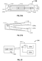
- FIG. 1B is a schematic diagram of a tissue clip according to another embodiment of the present disclosure.
- FIG. 1C is a schematic diagram of a tissue clip according to another embodiment of the present disclosure.
- FIG. 2 is a schematic diagram of an electrosurgical system utilizing tissue clips according to an embodiment of the present disclosure
- FIG. 3 is a system block diagram according to an embodiment of the present disclosure.
- FIG. 4 is a schematic diagram of a tissue clip according to another embodiment of the present disclosure.
- FIG. 5 is a system block diagram of the tissue clip of FIG. 4 ;
- FIG. 6 is a schematic diagram of a jaw portion according to an embodiment of the present disclosure.
- FIG. 7 is a schematic block diagram of an electrode suitable for use in a tissue clip according to another embodiment of the present disclosure.
- FIG. 8 is a schematic block diagram of an electrode suitable for use in a tissue clip according to another embodiment of the present disclosure.
- FIG. 9 is a schematic block diagram of an electrode suitable for use in a tissue clip according to another embodiment of the present disclosure.
- FIG. 10 is a cross sectional view of an electrode assembly of a tissue clip according to another embodiment of the present disclosure.
- FIG. 11 is a schematic diagram of a tissue clip according to another embodiment of the present disclosure.
- FIG. 12 is a system block diagram of the tissue clip of FIG. 11 ;
- FIG. 13A is a schematic block diagram of a tissue clip according to another embodiment of the present disclosure.
- FIG. 13B is a schematic diagram of an electrode arrangement of the tissue clip of FIG. 13A ;
- FIG. 14 is a schematic diagram of a tissue clip according to another embodiment of the present disclosure.
- FIG. 15 is a system block diagram of the tissue clip of FIG. 14 ;
- FIG. 16 is a schematic diagram of a tissue clip according to another embodiment of the present disclosure.
- FIG. 17 is a schematic diagram of a tissue clip according to another embodiment of the present disclosure.
- FIGS. 18A-18C are schematic diagrams of a tissue clip according to another embodiment of the present disclosure.
- FIG. 19 is a schematic diagram of a tissue clip according to another embodiment of the present disclosure.
- FIG. 20A is a schematic diagram of a tissue clip according to another embodiment of the present disclosure.
- FIG. 20B is a schematic diagram of a tissue clip according to yet another embodiment of the present disclosure.
- FIG. 21A is a schematic diagram of a tissue clip according to still another embodiment of the present disclosure.
- FIG. 21B is a schematic diagram of a tissue clip according to yet another embodiment of the present disclosure.
- FIG. 22 is a system block diagram of a tissue sealing system according to another embodiment of the present disclosure.
- proximal refers to the end of the apparatus that is closer to the user and the term “distal” refers to the end of the apparatus that is farther away from the user.
- distal refers to the end of the apparatus that is farther away from the user.
- clinical refers to any medical professional (e.g., doctor, surgeon, nurse, or the like) performing a medical procedure involving the use of embodiments described herein.
- Electromagnetic energy is generally classified by increasing frequency or decreasing wavelength into radio waves, microwaves, infrared, visible light, ultraviolet, X-rays and gamma-rays.
- microwave generally refers to electromagnetic waves in the frequency range of 300 megahertz (MHz) (3 ⁇ 10 8 cycles/second) to 300 gigahertz (GHz) (3 ⁇ 10 11 cycles/second).
- RF generally refers to electromagnetic waves having a lower frequency than microwaves.
- ultrasound generally refers to cyclic sound pressure with a frequency greater than the upper limit of human hearing.
- tissue and “vessel” may be used interchangeably since it is believed that the present disclosure may be employed to seal and cut tissue or seal and cut vessels utilizing the same principles described herein.
- the present disclosure is directed to the use of tissue clips in electrosurgical procedures.
- the tissue clips can be installed and configured to operate independently.
- the clip can stop blood flow immediately after installation and lets a surgeon proceed without waiting until the installed clip completes the vessel sealing procedure.
- tissue clips in a vessel sealing procedure involves providing a tissue clip that may be any one of the tissue clips described hereinbelow.
- the tissue clip is placed in the body of a patient approximately near tissue that will be sealed and/or cut.
- the tissue is then grasped by the tissue clip using one of the mechanisms described below. Energy is provided to the tissue from the power source and the grasped tissue is then sealed before the tissue clip is removed.
- the clip can be positioned on a vessel and then set into the closed position using a suitable surgical instrument such as forceps.
- a suitable surgical instrument such as forceps.
- the closed position provides vessel deformation and stops the blood flow.
- sealing time is not as crucial as for typical energy-based instruments. Longer sealing time lowers the requirements for a power source and, as such, enables more compact designs and reduces risk of thermal damage.
- the use of such tissue clips also enables the use of different sealing mechanisms such as soldering and photochemical tissue bonding which require a longer time then RF based sealing.
- Tissue clip 100 may be used for monopolar or bipolar electrosurgical procedures.
- Tissue clip 100 includes a body 101 and arm 102 .
- Arm 102 is connected to body 101 via a flexible joint 103 .
- a hinge or other pivoting mechanism may be used instead of flexible joint 103 .
- Flexible joint 103 allows the other end of arm 102 to move with respect to body 101 .
- Body 101 includes a protrusion or latch 104 which fixes or selectively locks arm 102 in the closed position.
- Tissue that is to be sealed is placed between body 101 and arm 102 .
- a gap may be provided by the flexible hinge 103 or stop members 190 ( FIG. 6 ) may be used to determine the gap between body 101 and arm 102 to provide optimal tissue thickness for a particular sealing mechanism. Typically, the gap is in the range of 0.001 inches to about 0.006 inches
- Tissue clip 100 includes electrodes 105 a and 105 b on arm 102 and body 101 , respectively.
- a power source 106 and control unit 107 are provided in body 101 to provide the necessary voltage to electrodes 105 a and 105 b .
- Control unit 107 transfers electrical power from power source 106 to electrodes 105 a and 105 b and applies a 100 KHz to 10 MHz frequency to electrodes 105 a and 105 b .
- the voltage profile provided by control unit 107 may be predetermined and stored in control unit 107 or provided by an external control unit 202 ( FIG. 2 ) via antenna 108 . Alternatively, the voltage profile may be adjusted by sensor array 170 ( FIG. 6 ) that determines one or more parameters of the grasped tissue measured before or during a sealing process.
- body 101 and arm 102 applies a sealing pressure to tissue grasped therebetween.
- the sealing pressure is in the range of 3 Kg/cm 2 to 16 Kg/cm 2 .
- Sealing pressure may be applied using different methods as shown in FIGS. 1A-1C . For instance, as shown in FIG. 1A , when arm 102 is locked in the closed position by protrusion 104 , a predetermined sealing pressure is maintained.
- a biasing member may be provided to generate the appropriate sealing pressure.
- a biasing member 132 may be substituted for hinge 103 , as shown in FIG. 1B or a biasing member 134 , 136 may be attached to electrodes 105 a and 105 b , as shown in FIG. 1C .
- biasing member 132 is used to move arm 102 from a first position to a second position closer to body 101 to grasp tissue.
- Biasing member 132 may be a spring loaded component that applies a predetermined sealing pressure to grasped tissue.
- biasing member 132 may be driven by a motor that may be manufactured using micro-electromechanical systems (MEMS) technology.
- the motor may be controlled by control unit 107 based on: a sealing pressure detected by sensor array 170 ( FIG. 6 ); an algorithm stored in control unit 107 ; an algorithm provided to control unit 107 from control unit 202 ; or a user input provided from control unit 202 .
- MEMS micro-electromechanical systems
- biasing members 134 and 136 may be attached to electrodes 105 a and 105 b , respectively. Although two biasing members are shown, a single biasing member attached to one electrode or both electrodes may be used. Biasing members 134 and 136 may be a spring-loaded component that moves at least one of the electrodes toward or away from each other to apply a predetermined sealing pressure to grasped tissue. Alternatively, biasing members 134 and 136 may be driven by a motor that may be manufactured using MEMS technology. The motor may be controlled by control unit 107 based on: a sealing pressure detected by sensor array 170 ( FIG. 6 ); an algorithm stored in control unit 107 ; an algorithm provided to control unit 107 from control unit 202 ; or a user input provided from control unit 202 .
- the tissue clips may be used with an external control unit 202 , as shown in FIGS. 2 and 3 .
- Control unit 202 may communicate with tissue clips 100 using suitable methods such as Bluetooth communication, radio communication, communication similar to the use of radio frequency identification tags or any other wireless communication.
- External control unit may transmit instructions to tissue clips 100 while tissue clips 100 may transmit results as well as measured tissue parameters.
- control unit 202 may send instructions to tissue clips 100 , which set the voltage and frequency according to the received instructions.
- One external control unit 202 may be used to control multiple tissue clips.
- FIG. 3 depicts a system block diagram of an embodiment of the present disclosure.
- Control unit 202 may include an input device 221 , a display 222 , memory 223 , processor 224 and a transceiver 225 coupled to an antenna 226 .
- Input device 221 may include buttons, knobs, switches or the like to input information for control unit 202 as well as tissue clips 100 .
- Display 222 may show the status of the vessel sealing procedure, parameters measured by sensor array 170 , status of individual tissue clips (e.g., malfunction, damaged, properly working, battery life, etc.) and time left in the electrosurgical procedure, time elapsed during the electrosurgical procedure.
- Memory 223 may be volatile type memory (e.g., RAM) and/or non-volatile type memory (e.g., flash media, disk media, etc.) that stores programs or sets of instructions that may be used to control the vessel sealing procedure.
- Processor 224 may be an integrated circuit or may include analog and/or logic circuitry that may be used to: execute instructions according to inputs provided by the input device 221 or sensor array 170 , execute instructions according to a program provided in memory 223 ; and control operation of control unit 202 and/or tissue clip 100 .
- the processor 224 sends a control signal to tissue clip 100 via transceiver 225 and antenna 226 .
- Control unit 202 transmits instructions to tissue clip 100 , which receives the instructions through antenna 108 .
- the instructions are decoded by control unit 107 , which then transfers power from power source 106 to electrodes 105 a and 105 b according to the received instructions.
- Control unit 107 may apply energy to a terminal 105 c that may be coupled to an electrode 1026 ( FIG. 10 ) to be used for cutting tissue.
- Control unit 107 may perform a diagnostic check on tissue clip 100 . If the tissue clip is defective or malfunctioning, a red light emitting diode (LED) 182 may be illuminated. If the tissue clip is functioning properly, a green LED 184 may be lit. Tissue clip also includes a sensor array 170 that determines properties of tissue between electrodes 105 a and 105 b as well as output voltage, current, impedance and power from control unit 107 . The detected tissue properties provide feedback to the control unit 107 or external control unit 202 to control the output of control unit 107 via an open loop or closed loop scheme.
- a red light emitting diode (LED) 182 may be illuminated. If the tissue clip is functioning properly, a green LED 184 may be lit.
- Tissue clip also includes a sensor array 170 that determines properties of tissue between electrodes 105 a and 105 b as well as output voltage, current, impedance and power from control unit 107 . The detected tissue properties provide feedback to the control unit 107 or external control unit
- Power source 106 may be a rechargeable battery and may be coupled to a terminal 160 that may be used to recharge power source 106 .
- arm 102 may have a contact 110 and body 101 may have a contact 111 as a safety check. The tissue clip is not operational until contact 110 is electrically coupled to contact 111 .
- FIGS. 4 and 5 depict a tissue clip according to another embodiment of the present disclosure shown generally as 200 .
- tissue clip 200 includes a control unit 207 .
- Control unit 207 includes a memory 210 and a processor 220 .
- Memory 210 may include a program or set of instructions that can be used to control the voltage output of control unit 207 .
- Tissue clip 200 may also include a terminal 230 that may be used to store instructions in memory 207 , determine the status of the tissue clip, record tissue parameters detected by sensor array 170 of tissue clip 200 .
- Tissue clip 200 may also include any of the biasing members described above with regard to FIGS. 1B and 1C .
- an array of sensors 170 a - 170 e are positioned within a cavity defined between arm 102 and body 101 .
- the sensors 170 a - 170 e are configured to automatically sense various properties of the tissue disposed between the arm 102 and body 101 and provide feedback to the control unit 107 , 207 or 202 during the sealing process.
- Such properties include, but are not limited to: tissue impedance, tissue type, tissue clarity, tissue compliance, temperature of the tissue or jaw members, water content in tissue, jaw opening angle, water motility in tissue, energy delivery sealing pressure and/or jaw closure pressure.
- the sensors 170 a - 170 e , control unit 107 , 207 , and/or 202 all cooperate to regulate the sealing procedure on tissue to conform to a predetermined algorithm.
- the arm 102 and/or body 101 may include one or more stop members 190 which limit the movement of the arm 102 and/or body 101 relative to one another.
- the stop member(s) 190 may be configured to extend from the electrode 105 a and/or 105 b a predetermined distance according to the specific material properties (e.g., compressive strength, thermal expansion, etc.) to yield a consistent and accurate gap distance “G” during sealing.
- the gap distance between the arm 102 and body 101 during sealing ranges from about 0.001 inches to about 0.006 inches and, in one particularly useful embodiment, between about 0.002 and about 0.003 inches.
- the non-conductive stop member(s) 190 may be molded onto the arm 102 and/or body 101 (e.g., overmolding, injection molding, etc.), stamped onto the arm 102 and/or body 101 or deposited (e.g., deposition) onto the arm 102 and/or body 101 .
- electrode 705 an electrode suitable for use in a tissue clip according to another embodiment of the present disclosure is shown generally as 705 .
- electrode 705 includes a stainless steel layer 710 and a copper layer 712 .
- Copper layer 712 partially covers stainless steel layer 710 .
- Electrode 705 may be formed by cladding a sheet of copper to a sheet of stainless steel and then stamping out or machining the bonded sheets into the shape of electrode 705 . Then a photolithography procedure may be used to etch portions of the copper from the edges of the electrode 705 leaving a heating section 714 . By etching out the copper from electrode 705 , only heating section 714 applies heat to tissue during a vessel sealing procedure.
- An energy source 720 which may include a control unit and/or battery as described above, may be used to provide electrosurgical energy to electrode 705 .
- Electrode 805 includes an insulative plate 804 that is a flex circuit. Flex circuits are used to assemble electronic circuits by mounting electronic devices on flexible plastic substrates. Such plastic substrates may include, but are not limited to, polyimide or polyether ether ketone (PEEK) film. Flex circuits may also be constructed by screen printing silver circuits onto polyester. As shown in FIG. 8 insulative plate 804 has a substrate 806 having circuit traces 812 formed thereon. Circuit traces 812 may be made from copper, silver, or any other electrical conductor. Circuit traces 812 may be formed by any suitable method.
- PEEK polyether ether ketone
- circuit traces 812 may be formed by adhering a conductive layer to substrate 806 . Using photolithography, a mask outlining circuit traces 812 may be formed and then the conductive layer may be etched to leave circuit traces 812 .
- Circuit traces 812 include contacts 810 that may be made from copper, silver or any other electrical conductor. Contacts 810 may be made from the same material as circuit traces 812 or from a material different from circuit traces 812 . Each contact 810 is operatively coupled to sensor array 820 via contact traces 816 . Contacts 810 and contact traces 816 are formed using the same techniques that may be used to form circuit traces 812 . The location of contacts 810 correspond to the location of piezo electric sensors 890 . Accordingly, when piezo electric sensors 890 measure or detect a tissue property, piezo electric sensors 890 provide a signal to controller 820 indicative of tissue properties via contacts 810 and contact traces 816 .
- Electrode 805 includes a seal plate 802 .
- Seal plate 802 is made from stainless steel, and as described above, has piezo electric sensors 890 disposed therein in locations 892 .
- Seal plate 802 may be formed by any suitable method. For instance, a layer of stainless steel may be provided and shaped to form seal plate 802 . Then, a photolithography mask is applied to seal plate 802 leaving locations 892 exposed. An etching solution is applied to seal plate 802 to etch away exposed locations 892 . Then the mask is removed leaving seal plate 802 with locations 892 etched away.
- piezo electric sensors 890 are placed in locations 892 of seal plate 802 and are coupled to contacts 810 of insulative plate 804 .
- Electrode 905 is located on an arm of a tissue clip (e.g., 102 of tissue clip 100 ) and has an outer layer 905 a formed from glass or other isolative non-stick material.
- Layer 905 b may be a flex circuit having a coil 910 formed on a flexible plastic substrate 912 .
- Such flexible plastic substrates 912 may be formed from, but are not limited to, polyimide, polyether ether ketone (PEEK) film or polylaminate. Flex circuits may also be constructed by screen printing silver circuits onto polyester.
- Coil 910 may be made from copper, silver, or any other electrical conductor. Coil 910 may be formed by any suitable method. For instance, coil 910 may be formed by adhering a conductive layer to flexible plastic substrate 912 . Using photolithography, a mask outlining coil 910 may be formed and then the conductive layer may be etched to leave coil 910 . Coil 910 may be coupled to an energy source 920 .
- Electrode 905 may have one or more coatings of a non-stick material. Therefore, tissue would not touch hot metal surfaces and sticking would be reduced. Further, since no heat energy would be applied to the electrode 905 (heat is generated in the tissue) the efficiency and speed of the seal would increase.
- an electrode assembly 1005 having a first electrode 1005 a located on an arm of the tissue clip (e.g., arm 102 of FIG. 1A ) and a second electrode 1005 b on a body of the tissue clip (e.g., body 101 of FIG. 1A ) are shown and are designed to effectively seal and cut tissue disposed between sealing surfaces 1012 a , 1012 b and 1022 a , 1022 b and cutting element 1026 of the opposing electrodes 1005 a and 1005 b , respectively. More particularly, and with respect to FIG.
- electrodes 1005 a and 1005 b include conductive tissue contacting surfaces 1012 a , 1012 b and 1022 a , 1022 b , respectively, disposed along substantially the entire longitudinal length thereof (e.g., extending substantially from the proximal to distal end of the respective arm and body of a tissue clip).
- Tissue contacting surfaces 1012 a , 1012 b and 1022 a , 1022 b may be attached to arm or body by stamping, by overmolding, by casting, by overmolding a casting, by coating a casting, by overmolding a stamped electrically conductive sealing plate and/or by overmolding a metal injection molded seal plate or in other suitable ways.
- the opposing electrodes 1005 a and 1005 b both include an insulator or insulative material 1014 and 1024 , respectively, disposed between each pair of electrically conductive sealing surfaces on the opposing electrodes 1005 a and 1005 b , e.g., between pairs 1012 a and 1012 b and between pairs 1022 a and 1022 b .
- Insulator 1014 is generally centered between tissue contacting surfaces 1012 a , 1012 b thereof along substantially the entire length the arm of the tissue clip.
- Insulators 1024 are generally centered along substantially the entire length of the body of the tissue clip. Insulators 1014 and 1024 are arranged such that the insulator 1014 generally opposes insulators 1024 .
- One or all of the insulators 1014 and 1024 may be made from a ceramic material due to the hardness of the ceramic and inherent ability to withstand high temperature fluctuations.
- one or both of the insulators 1014 and 1024 may be made from a material having a high Comparative Tracking Index (CTI) having a value in the range of about 300 to about 600 volts.
- CTI Comparative Tracking Index
- Examples of high CTI materials include nylons and syndiotactic polystyrenes.
- Suitable materials may also be utilized either alone or in combination, e.g., Nylons, Syndiotactic-polystryrene (SPS), Polybutylene Terephthalate (PBT), Polycarbonate (PC), Acrylonitrile Butadiene Styrene (ABS), Polyphthalamide (PPA), Polymide, Polyethylene Terephthalate (PET), Polyamide-imide (PAI), Acrylic (PMMA), Polystyrene (PS and HIPS), Polyether Sulfone (PES), Aliphatic Polyketone, Acetal (POM) Copolymer, Polyurethane (PU and TPU), Nylon with Polyphenylene-oxide dispersion and Acrylonitrile Styrene Acrylate.
- SPS Syndiotactic-polystryrene
- PBT Polybutylene Terephthalate
- PC Polycarbonate
- ABS Acrylonitrile Butadiene Styrene
- PPA Polyphthalamide
- PET Polyethylene Terephthal
- Electrode 1005 b includes an electrically conductive cutting element 1026 disposed substantially within insulators 1024 .
- the cutting element 1026 may play a dual role during the sealing and cutting processes, namely: 1) to provide the necessary gap distance between conductive surfaces 1012 a , 1012 b and 1022 a , 1022 b during the sealing process; and 2) to electrically energize the tissue along the previously formed tissue seal to cut the tissue along the seal.
- cutting element 1026 is electrically conductive; however, cutting element 1026 may be made from an insulative material with a conductive coating disposed thereon.
- the distance between cutting element 1026 and insulator 1014 may be disposed within the range of about 0.000 inches to about 0.040 inches to optimize the cutting effect.
- the opposing electrodes 1005 a and 1005 b are closed about tissue and the cutting element 1026 may form the requisite gap between the opposing sealing surfaces 1012 a , 1022 a and 1012 b , 1022 b .
- the cutting element 1026 is not necessarily energized such that the majority of the current is concentrated between opposing sealing surfaces, 1012 a and 1022 a and 1012 b and 1022 b , to effectively seal the tissue. Stop members (not shown) may also be employed to regulate the gap distance between the sealing surfaces in lieu of or in combination with cutting element 1026 .
- Cutting element 1026 may be configured to extend beyond the tissue contacting surfaces 1012 a , 1012 b and 1022 a , 1022 b such that cutting element 1026 acts as a stop member that creates a distance “d” between opposing conductive sealing surfaces 1012 a , 1022 a and 1012 b , 1022 b , which as mentioned above promotes accurate, consistent and effective tissue sealing.
- Distance “d” is typically within the above-mentioned gap range. In one embodiment, the distance “d” has a minimum distance of about 0.005 inches for proper effect without stopping the current flow between the cutting element 1026 and tissue contacting surfaces 1012 a , 1012 b and 1022 a , 1022 b .
- cutting element 1026 also prevents the opposing tissue contacting surfaces 1012 a , 1022 a and 1012 b , 1022 b from touching, which eliminates the chances of the forceps 10 , 100 shorting during the sealing process.
- sealing electrodes 1012 a , 1012 b and 1022 a , 1022 b are energized to a first potential “ ⁇ ” and cutting element 1026 is energized to the second electrical potential “+”.
- energy is transferred between cutting element 1026 and sealing electrodes 1012 a , 1012 b and 1022 a , 1022 b thereby cutting tissue disposed between electrodes 1005 a and 1005 b.
- control unit 107 is configured to determine when tissue grasped by the tissue clip is sealed based on tissue properties detected by sensor array 170 . When the control unit determines that the tissue has been sealed, control unit 107 automatically provides energy to terminal 105 c , which is coupled to cutting element 1026 , to cut the tissue grasped by the tissue clip.
- FIGS. 11 and 12 depict a tissue clip 1100 according to another embodiment of the present disclosure.
- tissue clip 1100 includes a control unit 1107 and a transducer 1105 .
- Control unit 1107 transfers energy from power source 106 to transducer 1105 to apply ultrasonic energy to tissue disposed between arm 102 and body 101 .
- antenna 108 may receive instructions from an external control unit 202 .
- control unit 1107 may include a memory and a processor.
- Memory may include a program or set of instructions that can be used to control the voltage output of control unit 1107 .
- Tissue clip 1100 may also include any of the biasing members described above with regard to FIGS. 1B and 1C .
- FIGS. 13A and 13B depict a tissue clip according to another embodiment of the present disclosure shown generally as 1300 .
- Tissue clip 1300 includes a power source 1330 , control unit 1320 and a light source 1310 .
- Light source 1310 may be coupled to long period fiber gratings 1305 a and 1305 b that emits light.
- Tissue clip 1300 may be used for optical soldering or photochemical tissue bonding.
- a soldering material may be applied (e.g., albumin) onto tissue between fiber gratings 1305 a and 1305 b .
- the soldering material may have a dye added thereto to reduce the amount of energy required due to the dye's absorption of certain wavelengths which is not absorbed by tissue.
- Tissue clip 1300 may also include any of the biasing members described above with regard to FIGS. 1B and 1C .
- a cutting element 1350 is disposed between fiber grating 1305 b .
- Cutting element 1350 is selectively moveable from a first position below the surface of fiber grating 1305 b to a second position to cut tissue grasped by tissue clip 1300 .
- FIG. 13 b depicts the cutting mechanism disposed in the body between fiber grating 1305 b
- cutting mechanism 1350 patent may be disposed in the arm between fiber rating 1305 a .
- Cutting mechanism 1350 may be incorporated into any of the embodiments described herein.
- cutting mechanism 1350 may be an electrode coupled to control unit 1320 . After a seal is completed, control unit 1320 transfers power from power source 1330 to cutting mechanism 1350 to electrically cut tissue.
- Cutting mechanism 1350 may also be a light source that emits a focused beam of light (i.e., a laser) to cut tissue.
- the light source may be a semiconductor laser or any other device that emits a focused beam of light.
- FIGS. 14 and 15 depict a tissue clip 1400 according to another embodiment of the present disclosure.
- tissue clip 1400 includes a control unit 1407 and an antenna array 1405 .
- Control unit 1407 transfers energy from power source 106 to antenna array 1405 to apply microwave energy to tissue disposed between arm 102 and body 101 .
- the microwave energy return to the control unit via return pad 1405 b .
- antenna 108 may receive instructions from an external control unit 202 .
- control unit 1407 may include a memory and a processor.
- Memory may include a program or set of instructions that can be used to control the voltage output of control unit 1407 .
- Tissue clip 1400 may also include any of the biasing members described above with regard to FIGS. 1B and 1C .
- FIG. 16 depicts a tissue clip according to another embodiment of the present disclosure shown generally as 1600 .
- Tissue clip 1600 includes an electrode assembly 1610 that is removably coupled to body 1620 .
- Electrode assembly 1610 includes electrodes 1615 that are coupled to terminals 1616 and 1618 . Electrodes 1615 are located on a pair of arms 1611 and 1612 that are coupled to each other via a flexible hinge 1613 . Terminals 1616 and 1618 are removably coupled to terminals 1626 and 1628 of body 1620 .
- Body 1620 includes a control unit 1624 and a power source 1622 .
- Body 1620 and electrode assembly 1610 may include any of the features described hereinabove.
- Electrode assembly 1610 may be absorbable while body 1620 may be reusable by sterilizing body 1620 and coupling body 1620 to a different electrode assembly 1610 .
- Tissue clip 1600 may also include any of the biasing members described above with regard to FIGS. 1B and 1C .
- FIG. 17 depicts a tissue clip according to another embodiment of the present disclosure shown generally as 1700 .
- Tissue clip 1700 includes an electrode assembly 1610 that is removably coupled to body 1710 .
- Electrode assembly 1610 includes electrodes 1615 that are coupled to terminals 1616 and 1618 . Electrodes 1615 are located on a pair of arms 1611 and 1612 that are coupled to each other via a flexible hinge 1613 . Terminals 1616 and 1618 are removably coupled to terminals 1626 and 1628 of body 1710 .
- Body 1710 includes a control unit 1624 and an antenna 1625 . Body 1710 and electrode assembly 1610 may include any of the features described hereinabove.
- a battery pack 1720 is removably coupled to body 1710 by coupling terminal 1722 to terminal 1712 .
- Battery pack 1720 includes a battery 1622 that may be a single use battery or a rechargeable battery.
- Electrode assembly 1610 may be absorbable while body 1710 and/or battery pack 1720 may be reusable by sterilizing body 1710 and/or battery pack 1720 and coupling body 1710 and/or battery pack 1720 to a different electrode assembly 1610 .
- Tissue clip 1700 may also include any of the biasing members described above with regard to FIGS. 1B and 1C .
- electrode assembly may be coupled to a housing (not shown). The housing may be configured to receive body 1710 and/or battery pack 1720 .
- FIGS. 18A-18C depict a tissue clip 1800 according to another embodiment of the present disclosure.
- Tissue clip 1800 includes an arm 1810 that is removably coupled to body 1820 .
- Arm 1810 includes an electrode 1814 and a retaining clip 1812 .
- Body 1820 includes an electrode 1824 and a retaining lip 1822 .
- Retaining clip 1812 and retaining lip 1822 are used to fix or selectively lock arm 1810 to body 1820 to grasp tissue disposed therebetween.
- Arm 1810 may include a power source 1815 , control unit 1816 and sensor array 1817 similar to any of the power sources, control units and/or sensor arrays described above.
- Body 1820 may include a power source 1825 , control unit 1826 and sensor array 1827 similar to any of the power sources, control units and/or sensor arrays described above.
- FIG. 19 depicts a tissue clip 1900 according to another embodiment of the present disclosure.
- Tissue clip 1900 includes a first arm 1901 and a second arm 1902 that are coupled together by a helical torsion spring 1910 .
- First arm 1901 includes a power source 1906 , control unit 1907 , antenna 1908 and electrode 1905 a .
- Second arm 1902 includes electrode 1905 b
- FIG. 19 shows the power source 1906 , control unit 1907 , and antenna 1908 in first arm 1901
- the power source 1906 , control unit 1907 , and antenna 1908 may be disposed in second arm 1902 or both the first arm 1901 and the second arm 1902 .
- Power source 1906 is similar to the power sources described hereinabove.
- Control unit 1907 stores a program that, when executed, causes tissue clip 1900 to seal tissue grasped between distal ends 1941 and 1942 of first arm 1901 and second arm 1902 , respectively.
- Antenna 1908 is configured to receive instructions from an external control unit or transmit information from a sensor (not shown) to an external control unit.
- Tissue clip 1900 may be effective in emergency situations where access to hospitals is limited such as rural areas or combat situations.
- a user presses proximal ends 1931 and 1932 of first arm 1901 and second arm 1902 , respectively, towards each other causing distal ends 1941 and 1942 to move away from each other.
- Tissue is placed between the distal ends 1941 and 1942 and then proximal ends 1931 and 1932 are released causing helical torsion spring 1920 to bias distal ends 1941 and 1941 toward each other to grasp tissue therebetween under the appropriate pressure to seal tissue.
- Stop members 1920 may be configured to extend from the electrode 1905 a and/or 1905 b a predetermined distance according to the specific material properties (e.g., compressive strength, thermal expansion, etc.) to yield a consistent and accurate gap distance during sealing.
- the gap distance between the first arm 1901 and second arm 1902 during sealing ranges from about 0.001 inches to about 0.006 inches and, in one particularly useful embodiment, between about 0.002 and about 0.003 inches.
- Helical torsion spring 1901 causes first arm 1901 and second arm 1902 to apply a sealing pressure to tissue grasped therebetween.
- the sealing pressure is in the range of 3 Kg/cm 2 to 16 Kg/cm 2 .
- FIG. 20A depicts a tissue clip according to another embodiment of the present disclosure.
- tissue clip 2000 includes a control portion 2010 and a clip portion 2020 .
- Control portion includes a power source 2006 , control unit 2007 , and antenna 2008 .
- Power source 2006 is similar to the power sources described hereinabove.
- Control unit 2007 stores a program that, when executed, causes tissue clip 2000 to seal tissue grasped between arm 2022 and arm 2023 .
- Antenna 2008 is configured to receive instructions from an external control unit or transmit information from a sensor (not shown) to an external control unit.
- Clip portion 2020 may be made from a shape memory alloy 2021, e.g., copper-zinc-aluminum-nickel, copper-aluminum-nickel, and nickel-titanium (NiTi) alloys.
- Shape memory alloy 2021 may exhibit a one way effect or two-way effect. When outside the body, shape memory material is in an open shape with arm 2022 and arm 2023 spaced apart from each other.
- heat within the body causes clip portion 2020 to heat up past the austenitic start temperature (A s ) causing the shape memory alloy 2021 to change to its original shape where arm 2022 and arm 2023 are positioned relatively closer to each other to grasp tissue disposed therebetween.
- a s austenitic start temperature
- Arm 2022 and arm 2023 include electrodes 2005 a and 2005 b , respectively. Electrodes 2005 a and 2005 b are disposed within insulators 2024 to electrically isolate electrodes 2005 a and 2005 b from shape memory alloy 2021. Insulator 2024 may be composed of any non-conductive material.
- Arm 2022 and arm 2023 are configured to yield a consistent and accurate gap distance, which may range from 0.001 inches to about 0.006 inches, during sealing when clip portion 2020 is in its original shape. Further, arm 2022 and arm 2023 may apply a sealing pressure to tissue grasped therebetween when clip portion 2020 is placed in its original austenitic shape. In one embodiment, the sealing pressure is in the range of 3 Kg/cm 2 to 16 Kg/cm 2 .
- control portion 2010 may be removably coupled to clip portion 2020 .
- control portion 2012 of tissue clip 2000 may only contain a power source 2006 .
- FIG. 20B depicts a tissue clip 2050 according to another embodiment of the present disclosure.
- Tissue clip 2050 is similar to clip portion 2020 described above.
- tissue clip 2050 includes receiving coil 2058 that is configured to receive energy from an external control unit as will be described below with regard to FIG. 22 .
- FIG. 21A depicts a tissue clip according to another embodiment of the present disclosure.
- tissue clip 2100 includes a control portion 2102 and clip portion 2110 .
- Control portion includes a power source 2106 , control unit 2107 , and antenna 2108 .
- Power source 2106 is similar to the power sources described hereinabove.
- Control unit 2107 stores a program that, when executed, causes tissue clip 2100 to seal tissue grasped between arm 2112 and second arm 2114 .
- Antenna 2108 is configured to receive instructions from an external control unit or transmit information from a sensor (not shown) to an external control unit.
- Clip portion 2110 includes electrodes 2105 a and 2105 b that apply energy to tissue grasped between arms 2112 and 2114 .
- a spring member 2130 is disposed in clip portion 2110 to bias arms 2112 and 2114 toward each other to grasp tissue therebetween.
- Arm 2112 and/or arm 2114 include stop members 2120 that are configured to yield a consistent and accurate gap distance, which may range from 0.001 inches to about 0.006 inches.
- spring member 2130 may be configured to achieve a desired gap between arm 2112 and arm 2114 .
- spring member 2130 may apply a sealing pressure to tissue grasped between arm 2112 and arm 2114 .
- the sealing pressure is in the range of 3 Kg/cm 2 to 16 Kg/cm 2 .
- control portion 2102 may be removably coupled to clip portion 2110 .
- control portion 2102 of tissue clip 2100 may only contain a power source 2106 .
- FIG. 21B depicts a tissue clip 2150 according to another embodiment of the present disclosure.
- Tissue clip 2150 is similar to clip portion 2110 described above.
- tissue clip 2050 includes a receiving coil 2158 that is configured to receive energy from an external control unit as will be described below with regard to FIG. 22 .
- FIG. 22 depicts a tissue clip system 2200 according to another embodiment of the present disclosure.
- Tissue clip system 2200 may use a power source placed outside of a tissue clip 2210 and the energy may be transferred from outside by excitation of an inductive current in a receiving coil placed inside the tissue clip.
- Different clips may have resonant receiving coils adjusted to different frequencies such that each clip can be supplied with power individually.
- the tissue clip may be controlled by varying the amplitude of the external electromagnetic field.
- tissue clip system 2200 includes a tissue clip 2210 and an external control unit 2220 .
- Control unit 2220 includes a power source 2206 , a control unit 2207 , and transmitting coil 2208 .
- Power source 2206 is similar to the power sources described hereinabove.
- Control unit 2207 stores a program that, when executed, causes tissue clip 2210 to seal tissue grasped between electrodes 2205 a and 2205 b .
- Transmitting coil 2208 generates an electromagnetic field that induces a current in receiving coil 2218 .
- the inductive current generated by receiving coil 2218 is supplied to electrodes 2205 a and 2205 b to seal tissue grasped therebetween.
- any one of the above described tissue clips may include features from any of the other described tissue clips.
- the use of an external power source as described in FIG. 22 may be incorporated into any of the tissue clips described above.
- tissue clip embodiments described herein can use light, microwave, RF, or resistive energy to thermally treat tissue or seal tissue (as defined herein).
Landscapes
- Health & Medical Sciences (AREA)
- Surgery (AREA)
- Life Sciences & Earth Sciences (AREA)
- Engineering & Computer Science (AREA)
- Biomedical Technology (AREA)
- Public Health (AREA)
- Nuclear Medicine, Radiotherapy & Molecular Imaging (AREA)
- Veterinary Medicine (AREA)
- General Health & Medical Sciences (AREA)
- Heart & Thoracic Surgery (AREA)
- Medical Informatics (AREA)
- Molecular Biology (AREA)
- Animal Behavior & Ethology (AREA)
- Reproductive Health (AREA)
- Vascular Medicine (AREA)
- Physics & Mathematics (AREA)
- Otolaryngology (AREA)
- Plasma & Fusion (AREA)
- Surgical Instruments (AREA)
Abstract
Description
Claims (19)
Priority Applications (1)
| Application Number | Priority Date | Filing Date | Title |
|---|---|---|---|
| US15/628,051 US10154848B2 (en) | 2011-07-11 | 2017-06-20 | Stand alone energy-based tissue clips |
Applications Claiming Priority (2)
| Application Number | Priority Date | Filing Date | Title |
|---|---|---|---|
| US13/179,960 US9844384B2 (en) | 2011-07-11 | 2011-07-11 | Stand alone energy-based tissue clips |
| US15/628,051 US10154848B2 (en) | 2011-07-11 | 2017-06-20 | Stand alone energy-based tissue clips |
Related Parent Applications (1)
| Application Number | Title | Priority Date | Filing Date |
|---|---|---|---|
| US13/179,960 Continuation US9844384B2 (en) | 2011-07-11 | 2011-07-11 | Stand alone energy-based tissue clips |
Publications (2)
| Publication Number | Publication Date |
|---|---|
| US20170281191A1 US20170281191A1 (en) | 2017-10-05 |
| US10154848B2 true US10154848B2 (en) | 2018-12-18 |
Family
ID=47506821
Family Applications (2)
| Application Number | Title | Priority Date | Filing Date |
|---|---|---|---|
| US13/179,960 Active 2032-07-16 US9844384B2 (en) | 2011-07-11 | 2011-07-11 | Stand alone energy-based tissue clips |
| US15/628,051 Expired - Fee Related US10154848B2 (en) | 2011-07-11 | 2017-06-20 | Stand alone energy-based tissue clips |
Family Applications Before (1)
| Application Number | Title | Priority Date | Filing Date |
|---|---|---|---|
| US13/179,960 Active 2032-07-16 US9844384B2 (en) | 2011-07-11 | 2011-07-11 | Stand alone energy-based tissue clips |
Country Status (3)
| Country | Link |
|---|---|
| US (2) | US9844384B2 (en) |
| EP (1) | EP2731530B1 (en) |
| WO (1) | WO2013009623A2 (en) |
Cited By (66)
| Publication number | Priority date | Publication date | Assignee | Title |
|---|---|---|---|---|
| US10441310B2 (en) | 2012-06-29 | 2019-10-15 | Ethicon Llc | Surgical instruments with curved section |
| US10441345B2 (en) | 2009-10-09 | 2019-10-15 | Ethicon Llc | Surgical generator for ultrasonic and electrosurgical devices |
| US10456193B2 (en) | 2016-05-03 | 2019-10-29 | Ethicon Llc | Medical device with a bilateral jaw configuration for nerve stimulation |
| US10485607B2 (en) | 2016-04-29 | 2019-11-26 | Ethicon Llc | Jaw structure with distal closure for electrosurgical instruments |
| US10517627B2 (en) | 2012-04-09 | 2019-12-31 | Ethicon Llc | Switch arrangements for ultrasonic surgical instruments |
| US10555769B2 (en) | 2016-02-22 | 2020-02-11 | Ethicon Llc | Flexible circuits for electrosurgical instrument |
| US10575892B2 (en) | 2015-12-31 | 2020-03-03 | Ethicon Llc | Adapter for electrical surgical instruments |
| US10595929B2 (en) | 2015-03-24 | 2020-03-24 | Ethicon Llc | Surgical instruments with firing system overload protection mechanisms |
| US10610286B2 (en) | 2015-09-30 | 2020-04-07 | Ethicon Llc | Techniques for circuit topologies for combined generator |
| US10639092B2 (en) | 2014-12-08 | 2020-05-05 | Ethicon Llc | Electrode configurations for surgical instruments |
| US10646269B2 (en) | 2016-04-29 | 2020-05-12 | Ethicon Llc | Non-linear jaw gap for electrosurgical instruments |
| US10688321B2 (en) | 2009-07-15 | 2020-06-23 | Ethicon Llc | Ultrasonic surgical instruments |
| US10702329B2 (en) | 2016-04-29 | 2020-07-07 | Ethicon Llc | Jaw structure with distal post for electrosurgical instruments |
| US10709469B2 (en) | 2016-01-15 | 2020-07-14 | Ethicon Llc | Modular battery powered handheld surgical instrument with energy conservation techniques |
| US10716615B2 (en) | 2016-01-15 | 2020-07-21 | Ethicon Llc | Modular battery powered handheld surgical instrument with curved end effectors having asymmetric engagement between jaw and blade |
| US10729494B2 (en) | 2012-02-10 | 2020-08-04 | Ethicon Llc | Robotically controlled surgical instrument |
| US10765470B2 (en) | 2015-06-30 | 2020-09-08 | Ethicon Llc | Surgical system with user adaptable techniques employing simultaneous energy modalities based on tissue parameters |
| US10779845B2 (en) | 2012-06-29 | 2020-09-22 | Ethicon Llc | Ultrasonic surgical instruments with distally positioned transducers |
| US10779879B2 (en) | 2014-03-18 | 2020-09-22 | Ethicon Llc | Detecting short circuits in electrosurgical medical devices |
| US10835307B2 (en) | 2001-06-12 | 2020-11-17 | Ethicon Llc | Modular battery powered handheld surgical instrument containing elongated multi-layered shaft |
| US10856929B2 (en) | 2014-01-07 | 2020-12-08 | Ethicon Llc | Harvesting energy from a surgical generator |
| US10898256B2 (en) | 2015-06-30 | 2021-01-26 | Ethicon Llc | Surgical system with user adaptable techniques based on tissue impedance |
| US10912603B2 (en) | 2013-11-08 | 2021-02-09 | Ethicon Llc | Electrosurgical devices |
| US10912580B2 (en) | 2013-12-16 | 2021-02-09 | Ethicon Llc | Medical device |
| US10925659B2 (en) | 2013-09-13 | 2021-02-23 | Ethicon Llc | Electrosurgical (RF) medical instruments for cutting and coagulating tissue |
| US10952788B2 (en) | 2015-06-30 | 2021-03-23 | Ethicon Llc | Surgical instrument with user adaptable algorithms |
| US10966747B2 (en) | 2012-06-29 | 2021-04-06 | Ethicon Llc | Haptic feedback devices for surgical robot |
| US10987123B2 (en) | 2012-06-28 | 2021-04-27 | Ethicon Llc | Surgical instruments with articulating shafts |
| US10993763B2 (en) | 2012-06-29 | 2021-05-04 | Ethicon Llc | Lockout mechanism for use with robotic electrosurgical device |
| US11051873B2 (en) | 2015-06-30 | 2021-07-06 | Cilag Gmbh International | Surgical system with user adaptable techniques employing multiple energy modalities based on tissue parameters |
| US11090104B2 (en) | 2009-10-09 | 2021-08-17 | Cilag Gmbh International | Surgical generator for ultrasonic and electrosurgical devices |
| US11096752B2 (en) | 2012-06-29 | 2021-08-24 | Cilag Gmbh International | Closed feedback control for electrosurgical device |
| US11129669B2 (en) | 2015-06-30 | 2021-09-28 | Cilag Gmbh International | Surgical system with user adaptable techniques based on tissue type |
| US11129670B2 (en) | 2016-01-15 | 2021-09-28 | Cilag Gmbh International | Modular battery powered handheld surgical instrument with selective application of energy based on button displacement, intensity, or local tissue characterization |
| US11179173B2 (en) | 2012-10-22 | 2021-11-23 | Cilag Gmbh International | Surgical instrument |
| US11229471B2 (en) | 2016-01-15 | 2022-01-25 | Cilag Gmbh International | Modular battery powered handheld surgical instrument with selective application of energy based on tissue characterization |
| US11266430B2 (en) | 2016-11-29 | 2022-03-08 | Cilag Gmbh International | End effector control and calibration |
| US11311326B2 (en) | 2015-02-06 | 2022-04-26 | Cilag Gmbh International | Electrosurgical instrument with rotation and articulation mechanisms |
| US11324527B2 (en) | 2012-11-15 | 2022-05-10 | Cilag Gmbh International | Ultrasonic and electrosurgical devices |
| US11337747B2 (en) | 2014-04-15 | 2022-05-24 | Cilag Gmbh International | Software algorithms for electrosurgical instruments |
| US11344362B2 (en) | 2016-08-05 | 2022-05-31 | Cilag Gmbh International | Methods and systems for advanced harmonic energy |
| US11382642B2 (en) | 2010-02-11 | 2022-07-12 | Cilag Gmbh International | Rotatable cutting implements with friction reducing material for ultrasonic surgical instruments |
| US11399855B2 (en) | 2014-03-27 | 2022-08-02 | Cilag Gmbh International | Electrosurgical devices |
| US11413060B2 (en) | 2014-07-31 | 2022-08-16 | Cilag Gmbh International | Actuation mechanisms and load adjustment assemblies for surgical instruments |
| US11426191B2 (en) | 2012-06-29 | 2022-08-30 | Cilag Gmbh International | Ultrasonic surgical instruments with distally positioned jaw assemblies |
| US11452525B2 (en) | 2019-12-30 | 2022-09-27 | Cilag Gmbh International | Surgical instrument comprising an adjustment system |
| US11471209B2 (en) | 2014-03-31 | 2022-10-18 | Cilag Gmbh International | Controlling impedance rise in electrosurgical medical devices |
| US11589916B2 (en) | 2019-12-30 | 2023-02-28 | Cilag Gmbh International | Electrosurgical instruments with electrodes having variable energy densities |
| US11660089B2 (en) | 2019-12-30 | 2023-05-30 | Cilag Gmbh International | Surgical instrument comprising a sensing system |
| US11666375B2 (en) | 2015-10-16 | 2023-06-06 | Cilag Gmbh International | Electrode wiping surgical device |
| US11684412B2 (en) | 2019-12-30 | 2023-06-27 | Cilag Gmbh International | Surgical instrument with rotatable and articulatable surgical end effector |
| US11696776B2 (en) | 2019-12-30 | 2023-07-11 | Cilag Gmbh International | Articulatable surgical instrument |
| US11723716B2 (en) | 2019-12-30 | 2023-08-15 | Cilag Gmbh International | Electrosurgical instrument with variable control mechanisms |
| US11759251B2 (en) | 2019-12-30 | 2023-09-19 | Cilag Gmbh International | Control program adaptation based on device status and user input |
| US11779329B2 (en) | 2019-12-30 | 2023-10-10 | Cilag Gmbh International | Surgical instrument comprising a flex circuit including a sensor system |
| US11779387B2 (en) | 2019-12-30 | 2023-10-10 | Cilag Gmbh International | Clamp arm jaw to minimize tissue sticking and improve tissue control |
| US11786291B2 (en) | 2019-12-30 | 2023-10-17 | Cilag Gmbh International | Deflectable support of RF energy electrode with respect to opposing ultrasonic blade |
| US11812957B2 (en) | 2019-12-30 | 2023-11-14 | Cilag Gmbh International | Surgical instrument comprising a signal interference resolution system |
| US11871955B2 (en) | 2012-06-29 | 2024-01-16 | Cilag Gmbh International | Surgical instruments with articulating shafts |
| US11890491B2 (en) | 2008-08-06 | 2024-02-06 | Cilag Gmbh International | Devices and techniques for cutting and coagulating tissue |
| US11911063B2 (en) | 2019-12-30 | 2024-02-27 | Cilag Gmbh International | Techniques for detecting ultrasonic blade to electrode contact and reducing power to ultrasonic blade |
| US11937863B2 (en) | 2019-12-30 | 2024-03-26 | Cilag Gmbh International | Deflectable electrode with variable compression bias along the length of the deflectable electrode |
| US11937866B2 (en) | 2019-12-30 | 2024-03-26 | Cilag Gmbh International | Method for an electrosurgical procedure |
| US11944366B2 (en) | 2019-12-30 | 2024-04-02 | Cilag Gmbh International | Asymmetric segmented ultrasonic support pad for cooperative engagement with a movable RF electrode |
| US11950797B2 (en) | 2019-12-30 | 2024-04-09 | Cilag Gmbh International | Deflectable electrode with higher distal bias relative to proximal bias |
| US11986201B2 (en) | 2019-12-30 | 2024-05-21 | Cilag Gmbh International | Method for operating a surgical instrument |
Families Citing this family (70)
| Publication number | Priority date | Publication date | Assignee | Title |
|---|---|---|---|---|
| US7364577B2 (en) | 2002-02-11 | 2008-04-29 | Sherwood Services Ag | Vessel sealing system |
| ES2332143T3 (en) | 2001-04-06 | 2010-01-27 | Covidien Ag | SHUTTER AND DIVIDER OF GLASSES WITH NON-CONDUCTIVE BUMPER MEMBERS. |
| US7628791B2 (en) | 2005-08-19 | 2009-12-08 | Covidien Ag | Single action tissue sealer |
| US8298232B2 (en) | 2006-01-24 | 2012-10-30 | Tyco Healthcare Group Lp | Endoscopic vessel sealer and divider for large tissue structures |
| US8114122B2 (en) | 2009-01-13 | 2012-02-14 | Tyco Healthcare Group Lp | Apparatus, system, and method for performing an electrosurgical procedure |
| US8187273B2 (en) | 2009-05-07 | 2012-05-29 | Tyco Healthcare Group Lp | Apparatus, system, and method for performing an electrosurgical procedure |
| US8430876B2 (en) | 2009-08-27 | 2013-04-30 | Tyco Healthcare Group Lp | Vessel sealer and divider with knife lockout |
| US8133254B2 (en) | 2009-09-18 | 2012-03-13 | Tyco Healthcare Group Lp | In vivo attachable and detachable end effector assembly and laparoscopic surgical instrument and methods therefor |
| US8112871B2 (en) | 2009-09-28 | 2012-02-14 | Tyco Healthcare Group Lp | Method for manufacturing electrosurgical seal plates |
| US8939972B2 (en) | 2011-05-06 | 2015-01-27 | Covidien Lp | Surgical forceps |
| US8685009B2 (en) | 2011-05-16 | 2014-04-01 | Covidien Lp | Thread-like knife for tissue cutting |
| US8852185B2 (en) | 2011-05-19 | 2014-10-07 | Covidien Lp | Apparatus for performing an electrosurgical procedure |
| US9615877B2 (en) | 2011-06-17 | 2017-04-11 | Covidien Lp | Tissue sealing forceps |
| US8745840B2 (en) | 2011-07-11 | 2014-06-10 | Covidien Lp | Surgical forceps and method of manufacturing thereof |
| US9039732B2 (en) | 2011-07-11 | 2015-05-26 | Covidien Lp | Surgical forceps |
| US8852186B2 (en) | 2011-08-09 | 2014-10-07 | Covidien Lp | Microwave sensing for tissue sealing |
| US8845636B2 (en) | 2011-09-16 | 2014-09-30 | Covidien Lp | Seal plate with insulation displacement connection |
| US8864795B2 (en) | 2011-10-03 | 2014-10-21 | Covidien Lp | Surgical forceps |
| US8968309B2 (en) | 2011-11-10 | 2015-03-03 | Covidien Lp | Surgical forceps |
| US8968310B2 (en) | 2011-11-30 | 2015-03-03 | Covidien Lp | Electrosurgical instrument with a knife blade lockout mechanism |
| US9113897B2 (en) | 2012-01-23 | 2015-08-25 | Covidien Lp | Partitioned surgical instrument |
| US8968360B2 (en) | 2012-01-25 | 2015-03-03 | Covidien Lp | Surgical instrument with resilient driving member and related methods of use |
| US8747434B2 (en) | 2012-02-20 | 2014-06-10 | Covidien Lp | Knife deployment mechanisms for surgical forceps |
| US8961514B2 (en) * | 2012-03-06 | 2015-02-24 | Covidien Lp | Articulating surgical apparatus |
| US9375282B2 (en) | 2012-03-26 | 2016-06-28 | Covidien Lp | Light energy sealing, cutting and sensing surgical device |
| US9265569B2 (en) | 2012-03-29 | 2016-02-23 | Covidien Lp | Method of manufacturing an electrosurgical forceps |
| US9668807B2 (en) | 2012-05-01 | 2017-06-06 | Covidien Lp | Simplified spring load mechanism for delivering shaft force of a surgical instrument |
| US9820765B2 (en) | 2012-05-01 | 2017-11-21 | Covidien Lp | Surgical instrument with stamped double-flange jaws |
| US8968311B2 (en) | 2012-05-01 | 2015-03-03 | Covidien Lp | Surgical instrument with stamped double-flag jaws and actuation mechanism |
| US9375258B2 (en) | 2012-05-08 | 2016-06-28 | Covidien Lp | Surgical forceps |
| US9039731B2 (en) | 2012-05-08 | 2015-05-26 | Covidien Lp | Surgical forceps including blade safety mechanism |
| US9265566B2 (en) | 2012-10-16 | 2016-02-23 | Covidien Lp | Surgical instrument |
| WO2015017991A1 (en) | 2013-08-07 | 2015-02-12 | Covidien Lp | Bipolar surgical instrument |
| EP3030176B1 (en) | 2013-08-07 | 2022-09-28 | Covidien LP | Bipolar surgical instrument with tissue stop |
| USD788302S1 (en) | 2013-10-01 | 2017-05-30 | Covidien Lp | Knife for endoscopic electrosurgical forceps |
| US9987077B2 (en) | 2014-09-17 | 2018-06-05 | Covidien Lp | Surgical instrument having a bipolar end effector assembly and a deployable monopolar assembly |
| US9987076B2 (en) | 2014-09-17 | 2018-06-05 | Covidien Lp | Multi-function surgical instruments |
| US9918785B2 (en) | 2014-09-17 | 2018-03-20 | Covidien Lp | Deployment mechanisms for surgical instruments |
| US10039592B2 (en) | 2014-09-17 | 2018-08-07 | Covidien Lp | Deployment mechanisms for surgical instruments |
| US10080605B2 (en) | 2014-09-17 | 2018-09-25 | Covidien Lp | Deployment mechanisms for surgical instruments |
| US10172612B2 (en) | 2015-01-21 | 2019-01-08 | Covidien Lp | Surgical instruments with force applier and methods of use |
| USD844139S1 (en) | 2015-07-17 | 2019-03-26 | Covidien Lp | Monopolar assembly of a multi-function surgical instrument |
| USD844138S1 (en) | 2015-07-17 | 2019-03-26 | Covidien Lp | Handle assembly of a multi-function surgical instrument |
| US11446078B2 (en) | 2015-07-20 | 2022-09-20 | Megadyne Medical Products, Inc. | Electrosurgical wave generator |
| WO2017031712A1 (en) | 2015-08-26 | 2017-03-02 | Covidien Lp | Electrosurgical end effector assemblies and electrosurgical forceps configured to reduce thermal spread |
| US10172672B2 (en) | 2016-01-11 | 2019-01-08 | Covidien Lp | Jaw force control for electrosurgical forceps |
| US10426543B2 (en) | 2016-01-23 | 2019-10-01 | Covidien Lp | Knife trigger for vessel sealer |
| US10537381B2 (en) | 2016-02-26 | 2020-01-21 | Covidien Lp | Surgical instrument having a bipolar end effector assembly and a deployable monopolar assembly |
| US10517665B2 (en) * | 2016-07-14 | 2019-12-31 | Covidien Lp | Devices and methods for tissue sealing and mechanical clipping |
| US10631887B2 (en) | 2016-08-15 | 2020-04-28 | Covidien Lp | Electrosurgical forceps for video assisted thoracoscopic surgery and other surgical procedures |
| EP3512445A4 (en) * | 2016-09-16 | 2020-08-12 | Invuity, Inc. | Methods and apparatus for electrosurgical illumination |
| US10813695B2 (en) | 2017-01-27 | 2020-10-27 | Covidien Lp | Reflectors for optical-based vessel sealing |
| US11172980B2 (en) | 2017-05-12 | 2021-11-16 | Covidien Lp | Electrosurgical forceps for grasping, treating, and/or dividing tissue |
| US10973567B2 (en) | 2017-05-12 | 2021-04-13 | Covidien Lp | Electrosurgical forceps for grasping, treating, and/or dividing tissue |
| USD843574S1 (en) | 2017-06-08 | 2019-03-19 | Covidien Lp | Knife for open vessel sealer |
| USD854684S1 (en) | 2017-06-08 | 2019-07-23 | Covidien Lp | Open vessel sealer with mechanical cutter |
| USD854149S1 (en) | 2017-06-08 | 2019-07-16 | Covidien Lp | End effector for open vessel sealer |
| US11154348B2 (en) | 2017-08-29 | 2021-10-26 | Covidien Lp | Surgical instruments and methods of assembling surgical instruments |
| EP3687420A4 (en) * | 2017-09-29 | 2021-04-14 | Helsinki Surgical Instruments AB | A device for applying external pressure on a surface of an anatomical object |
| US11241275B2 (en) | 2018-03-21 | 2022-02-08 | Covidien Lp | Energy-based surgical instrument having multiple operational configurations |
| US11123132B2 (en) | 2018-04-09 | 2021-09-21 | Covidien Lp | Multi-function surgical instruments and assemblies therefor |
| US10780544B2 (en) | 2018-04-24 | 2020-09-22 | Covidien Lp | Systems and methods facilitating reprocessing of surgical instruments |
| US10828756B2 (en) | 2018-04-24 | 2020-11-10 | Covidien Lp | Disassembly methods facilitating reprocessing of multi-function surgical instruments |
| US11376062B2 (en) | 2018-10-12 | 2022-07-05 | Covidien Lp | Electrosurgical forceps |
| US11471211B2 (en) | 2018-10-12 | 2022-10-18 | Covidien Lp | Electrosurgical forceps |
| US11350982B2 (en) | 2018-12-05 | 2022-06-07 | Covidien Lp | Electrosurgical forceps |
| US11523861B2 (en) | 2019-03-22 | 2022-12-13 | Covidien Lp | Methods for manufacturing a jaw assembly for an electrosurgical forceps |
| US11617612B2 (en) | 2020-03-16 | 2023-04-04 | Covidien Lp | Forceps with linear trigger mechanism |
| US11660109B2 (en) | 2020-09-08 | 2023-05-30 | Covidien Lp | Cutting elements for surgical instruments such as for use in robotic surgical systems |
| US11925406B2 (en) | 2020-09-14 | 2024-03-12 | Covidien Lp | End effector assemblies for surgical instruments |
Citations (396)
| Publication number | Priority date | Publication date | Assignee | Title |
|---|---|---|---|---|
| GB623316A (en) | 1947-04-29 | 1949-05-16 | Thomas Wallace Parker | Improvements in and relating to building units |
| SU401367A1 (en) | 1971-10-05 | 1973-10-12 | Тернопольский государственный медицинский институт | BIAKTIVNYE ELECTRO SURGICAL INSTRUMENT |
| DE2415263A1 (en) | 1974-03-29 | 1975-10-02 | Aesculap Werke Ag | Surgical H.F. coagulation probe has electrode tongs - with exposed ends of insulated conductors forming tong-jaws |
| DE2514501A1 (en) | 1975-04-03 | 1976-10-21 | Karl Storz | Bipolar coagulation instrument for endoscopes - has two high frequency electrodes looped over central insulating piece |
| DE2627679A1 (en) | 1975-06-26 | 1977-01-13 | Marcel Lamidey | HEMATISTIC HIGH FREQUENCY EXTRACTOR FORCEPS |
| GB1490585A (en) | 1974-05-30 | 1977-11-02 | Wolf Gmbh Richard | Devices for removing dividing or coagulating tissues |
| USD249549S (en) | 1976-10-22 | 1978-09-19 | Aspen Laboratories, Inc. | Electrosurgical handle |
| USD263020S (en) | 1980-01-22 | 1982-02-16 | Rau Iii David M | Retractable knife |
| JPS61501068A (en) | 1984-01-30 | 1986-05-29 | ハルコフスキイ ナウチノ−イススレドワテルスキイ インスチチユ−ト オブスチエイ イ ネオトロジノイ ヒルルギイ | bipolar electrosurgical instrument |
| DE3423356C2 (en) | 1984-06-25 | 1986-06-26 | Berchtold Medizin-Elektronik GmbH & Co, 7200 Tuttlingen | Electrosurgical high frequency cutting instrument |
| DE3612646A1 (en) | 1985-04-16 | 1987-04-30 | Ellman International | Electrosurgical handle piece for blades, needles and forceps |
| DE8712328U1 (en) | 1987-09-11 | 1988-02-18 | Jakoubek, Franz, 7201 Emmingen-Liptingen, De | |
| USD295894S (en) | 1985-09-26 | 1988-05-24 | Acme United Corporation | Disposable surgical scissors |
| USD295893S (en) | 1985-09-25 | 1988-05-24 | Acme United Corporation | Disposable surgical clamp |
| USD298353S (en) | 1986-05-06 | 1988-11-01 | Vitalmetrics, Inc. | Handle for surgical instrument |
| USD299413S (en) | 1985-07-17 | 1989-01-17 | The Stanley Works | Folding pocket saw handle |
| WO1989000757A1 (en) | 1987-07-10 | 1989-01-26 | Raychem Limited | Electrical wire |
| GB2213416A (en) | 1987-12-11 | 1989-08-16 | Stanley Works Ltd | Blade-carriers for retractable bladeknives |
| GB2214430A (en) | 1988-01-20 | 1989-09-06 | Nigel Mark Goble | Diathermy unit |
| EP0467501A1 (en) | 1990-07-20 | 1992-01-22 | Everest Medical Corporation | Polypectome snare with bipolar electrodes |
| WO1992004873A1 (en) | 1990-09-13 | 1992-04-02 | Noord Andrew J Van | Electrosurgical knife |
| WO1992006642A1 (en) | 1990-10-17 | 1992-04-30 | Boston Scientific Corporation | Surgical instrument and method |
| EP0509670A2 (en) | 1991-04-15 | 1992-10-21 | Everest Medical Corporation | Bipolar electrosurgical scalpel with paired loop electrodes |
| JPH055106A (en) | 1990-07-31 | 1993-01-14 | Matsushita Electric Works Ltd | Production of alloy sintered body |
| JPH0540112A (en) | 1991-02-08 | 1993-02-19 | Tokico Ltd | Analyzing apparatus of component of sample liquid |
| US5201900A (en) | 1992-02-27 | 1993-04-13 | Medical Scientific, Inc. | Bipolar surgical clip |
| EP0306123B1 (en) | 1987-09-04 | 1993-08-11 | John C. Jaeger | Surgical instrument with adjustable angle of operation |
| WO1993019681A1 (en) | 1992-03-31 | 1993-10-14 | Valleylab, Inc. | Electrosurgical bipolar cutting handpiece |
| WO1993021845A1 (en) | 1992-05-01 | 1993-11-11 | Hemostatix Corporation | Bipolar surgical snare and methods of use |
| EP0572131A1 (en) | 1992-05-21 | 1993-12-01 | Everest Medical Corporation | Surgical scissors with bipolar coagulation feature |
| WO1994000059A1 (en) | 1992-06-24 | 1994-01-06 | Microsurge, Inc. | Reusable endoscopic surgical instrument |
| USD343453S (en) | 1993-05-05 | 1994-01-18 | Laparomed Corporation | Handle for laparoscopic surgical instrument |
| JPH0630945A (en) | 1992-05-19 | 1994-02-08 | Olympus Optical Co Ltd | Suturing apparatus |
| CA2104423A1 (en) | 1992-08-24 | 1994-02-25 | Boris Zvenyatsky | Handle for endoscopic instruments and jaw structure |
| EP0589453A2 (en) | 1992-09-23 | 1994-03-30 | United States Surgical Corporation | Bipolar surgical forceps |
| EP0589555A1 (en) | 1992-08-21 | 1994-03-30 | Everest Medical Corporation | Bipolar Electrosurgical Forceps |
| WO1994008524A1 (en) | 1992-10-09 | 1994-04-28 | Hemostatix Corporation | Electrosurgical instruments having a detachable working end |
| JPH06121797A (en) | 1992-02-27 | 1994-05-06 | United States Surgical Corp | Equipment and method for performing intracutaneous stapling of body tissue |
| USD348930S (en) | 1991-10-11 | 1994-07-19 | Ethicon, Inc. | Endoscopic stapler |
| USD349341S (en) | 1992-10-28 | 1994-08-02 | Microsurge, Inc. | Endoscopic grasper |
| WO1994020025A1 (en) | 1993-03-04 | 1994-09-15 | Microsurge, Inc. | Surgical instrument |
| JPH06285078A (en) | 1993-04-05 | 1994-10-11 | Olympus Optical Co Ltd | Forceps |
| EP0624348A2 (en) | 1993-05-06 | 1994-11-17 | United States Surgical Corporation | Bipolar electrosurgical instruments |
| JPH06343644A (en) | 1993-05-04 | 1994-12-20 | Gyrus Medical Ltd | Surgical peritoneoscope equipment |
| JPH06511401A (en) | 1991-06-07 | 1994-12-22 | バイタル メディカル プロダクツ コーポレイション | Bipolar electrosurgical endoscopic instrument and its method of use |
| USD354564S (en) | 1993-06-25 | 1995-01-17 | Richard-Allan Medical Industries, Inc. | Surgical clip applier |
| WO1995002369A1 (en) | 1993-07-12 | 1995-01-26 | Gyrus Medical Limited | An electrosurgical generator |
| DE4303882C2 (en) | 1993-02-10 | 1995-02-09 | Kernforschungsz Karlsruhe | Combination instrument for separation and coagulation for minimally invasive surgery |
| WO1995007662A1 (en) | 1993-09-14 | 1995-03-23 | Microsurge, Inc. | Endoscopic surgical instrument with guided jaws and ratchet control |
| EP0648475A1 (en) | 1993-10-07 | 1995-04-19 | United States Surgical Corporation | Curved knife for linear staplers |
| USD358887S (en) | 1993-12-02 | 1995-05-30 | Cobot Medical Corporation | Combined cutting and coagulating forceps |
| WO1995015124A1 (en) | 1993-12-02 | 1995-06-08 | Cabot Technology Corporation | Cutting and coagulating forceps |
| WO1995020360A1 (en) | 1994-01-31 | 1995-08-03 | Valleylab, Inc. | Telescoping bipolar electrode for non-invasive medical procedures |
| DE4403252A1 (en) | 1994-02-03 | 1995-08-10 | Michael Hauser | Instrument shaft for min. invasive surgery |
| WO1995020921A1 (en) | 1994-02-07 | 1995-08-10 | Andrea Budic | A device for holding surgical instruments and for the manual control of the electrical supply thereto |
| JPH07265328A (en) | 1993-11-01 | 1995-10-17 | Gyrus Medical Ltd | Electrode assembly for electric surgery device and electric surgery device using it |
| EP0364216B1 (en) | 1988-10-13 | 1996-01-17 | Gyrus Medical Limited | Screening and monitoring instrument |
| WO1996005776A1 (en) | 1993-08-16 | 1996-02-29 | Vesta Medical, Inc. | Coagulating forceps |
| JPH0856955A (en) | 1994-06-29 | 1996-03-05 | Gyrus Medical Ltd | Electric surgical apparatus |
| WO1996011635A1 (en) | 1994-10-17 | 1996-04-25 | Applied Medical Resources Corporation | Atraumatic surgical clamping instrument |
| WO1996013218A1 (en) | 1994-10-28 | 1996-05-09 | Desai Ashvin H | Endoscopic surgical instrument |
| WO1996022056A1 (en) | 1995-01-20 | 1996-07-25 | Inbae Yoon | Multifunctional instrument with interchangeable operating units for performing endoscopic procedures |
| DE19515914C1 (en) | 1995-05-02 | 1996-07-25 | Aesculap Ag | Tong or scissor-shaped surgical instrument |
| DE19506363A1 (en) | 1995-02-24 | 1996-08-29 | Frost Lore Geb Haupt | Non-invasive thermometry in organs under hyperthermia and coagulation conditions |
| JPH08252263A (en) | 1994-12-21 | 1996-10-01 | Gyrus Medical Ltd | Electronic surgical incision apparatus and electronic surgical incision device using said apparatus |
| JPH08289895A (en) | 1995-04-21 | 1996-11-05 | Olympus Optical Co Ltd | Suture device |
| DE29616210U1 (en) | 1996-09-18 | 1996-11-14 | Winter & Ibe Olympus | Handle for surgical instruments |
| JPH08317934A (en) | 1995-04-12 | 1996-12-03 | Ethicon Endo Surgery Inc | Hemostatic device for electric surgery with adaptable electrode |
| JPH08317936A (en) | 1995-01-18 | 1996-12-03 | Ethicon Endo Surgery Inc | Hemostatic device for electric surgery provided with recessed type and/or crossed type electrode |
| JPH09538A (en) | 1995-06-21 | 1997-01-07 | Fuji Photo Optical Co Ltd | High-frequency medical treatment instrument |
| WO1997000646A1 (en) | 1995-06-23 | 1997-01-09 | Gyrus Medical Limited | An electrosurgical instrument |
| WO1997000647A1 (en) | 1995-06-23 | 1997-01-09 | Gyrus Medical Limited | An electrosurgical instrument |
| JPH0910223A (en) | 1995-06-23 | 1997-01-14 | Gyrus Medical Ltd | Generator and system for electric operation |
| WO1997010764A1 (en) | 1995-09-19 | 1997-03-27 | Valleylab Inc. | Vascular tissue sealing pressure control and method |
| DE19608716C1 (en) | 1996-03-06 | 1997-04-17 | Aesculap Ag | Bipolar surgical holding instrument |
| JPH09122138A (en) | 1995-10-20 | 1997-05-13 | Ethicon Endo Surgery Inc | Apparatus for operation |
| WO1997018768A1 (en) | 1995-11-22 | 1997-05-29 | Arthrocare Corporation | Systems and methods for electrosurgical myocardial revascularization |
| WO1997024073A1 (en) | 1995-12-29 | 1997-07-10 | Gyrus Medical Limited | An electrosurgical instrument and an electrosurgical electrode assembly |
| WO1997024993A1 (en) | 1996-01-09 | 1997-07-17 | Gyrus Medical Limited | An electrosurgical instrument |
| USD384413S (en) | 1994-10-07 | 1997-09-30 | United States Surgical Corporation | Endoscopic suturing instrument |
| JPH10195A (en) | 1996-03-05 | 1998-01-06 | Ethicon Endo Surgery Inc | Surgical suturing machine with fixing mechanism |
| JPH1024051A (en) | 1995-09-20 | 1998-01-27 | Olympus Optical Co Ltd | Coagulation forceps with separating function |
| EP0541930B1 (en) | 1991-10-17 | 1998-03-25 | Smith & Nephew, Inc. | Transmission link for use in surgical instruments |
| WO1998014124A1 (en) | 1996-10-04 | 1998-04-09 | Klieman Charles H | Surgical instrument for endoscopic and general surgery |
| DE19751106A1 (en) | 1996-11-27 | 1998-05-28 | Eastman Kodak Co | Laser printer with array of laser diodes |
| JPH10155798A (en) | 1996-12-04 | 1998-06-16 | Asahi Optical Co Ltd | Hot biopsy clamp for endoscope |
| WO1998027880A1 (en) | 1996-12-20 | 1998-07-02 | Gyrus Medical Limited | Electrosurgical generator and system for underwater operation |
| WO1998031290A1 (en) | 1997-01-15 | 1998-07-23 | Electroscope, Inc. | Bipolar vaporization apparatus and method for arthroscopy |
| USH1745H (en) | 1995-09-29 | 1998-08-04 | Paraschac; Joseph F. | Electrosurgical clamping device with insulation limited bipolar electrode |
| US5792138A (en) * | 1996-02-22 | 1998-08-11 | Apollo Camera, Llc | Cordless bipolar electrocautery unit with automatic power control |
| WO1998043264A1 (en) | 1997-03-25 | 1998-10-01 | Ut Automotive Dearborn, Inc. | Switching device with secondary switching function |
| EP0878169A1 (en) | 1997-05-14 | 1998-11-18 | Ethicon Endo-Surgery, Inc. | Improved electrosurgical hemostatic device including an anvil |
| USD402028S (en) | 1997-10-10 | 1998-12-01 | Invasatec, Inc. | Hand controller for medical system |
| WO1999003407A1 (en) | 1997-07-18 | 1999-01-28 | Gyrus Medical Limited | An electrosurgical instrument |
| WO1999003408A1 (en) | 1997-07-18 | 1999-01-28 | Gyrus Medical Limited | An electrosurgical instrument |
| WO1999003414A1 (en) | 1997-07-18 | 1999-01-28 | Medtronic, Inc. | Tissue sealing electrosurgery device and methods of sealing tissue |
| WO1999003409A1 (en) | 1997-07-18 | 1999-01-28 | Gyrus Medical Limited | An electrosurgical instrument |
| JPH1147150A (en) | 1997-08-06 | 1999-02-23 | Olympus Optical Co Ltd | Endoscopic surgery appliance |
| WO1999012488A1 (en) | 1997-09-10 | 1999-03-18 | Sherwood Services Ag | Bipolar instrument for vessel fusion |
| US5891142A (en) * | 1996-12-06 | 1999-04-06 | Eggers & Associates, Inc. | Electrosurgical forceps |
| USD408018S (en) | 1996-03-12 | 1999-04-13 | Mcnaughton Patrick J | Switch guard |
| WO1999023933A2 (en) | 1997-11-12 | 1999-05-20 | Valleylab, Inc. | Bipolar electrosurgical instrument with replaceable electrodes |
| WO1999023959A1 (en) | 1997-11-12 | 1999-05-20 | Valleylab, Inc. | Bipolar electrosurgical instrument for sealing vessels |
| DE19751108A1 (en) | 1997-11-18 | 1999-05-20 | Beger Frank Michael Dipl Desig | Electrosurgical operation tool, especially for diathermy |
| WO1999025261A1 (en) | 1997-11-14 | 1999-05-27 | Sherwood Services Ag | Laparoscopic bipolar electrosurgical instrument |
| EP0923907A1 (en) | 1997-12-19 | 1999-06-23 | Gyrus Medical Limited | An electrosurgical instrument |
| JPH11169381A (en) | 1997-12-15 | 1999-06-29 | Olympus Optical Co Ltd | High frequency treating device |
| JPH11192238A (en) | 1997-10-10 | 1999-07-21 | Ethicon Endo Surgery Inc | Ultrasonic forceps coagulation device improved of pivot-attaching of forceps arm |
| WO1999040857A1 (en) | 1998-02-12 | 1999-08-19 | Consortium Management Services Group, Inc. | Bonding of soft biological tissues by passing high frequency electric current therethrough |
| WO1999040861A1 (en) | 1998-02-17 | 1999-08-19 | Baker James A | Radiofrequency medical instrument for vessel welding |
| EP0640317B1 (en) | 1993-07-22 | 1999-09-15 | Ethicon, Inc. | Electrosurgical hemostatic device |
| WO1999051158A1 (en) | 1998-04-03 | 1999-10-14 | Gyrus Medical Limited | An electrode assembly for an electrosurgical instrument |
| EP0950378A1 (en) | 1998-04-16 | 1999-10-20 | Silhouet-Tone (Europe) S.A. | Hair removal electrolysis apparatus |
| USD416089S (en) | 1996-04-08 | 1999-11-02 | Richard-Allan Medical Industries, Inc. | Endoscopic linear stapling and dividing surgical instrument |
| WO1999066850A1 (en) | 1998-06-22 | 1999-12-29 | Lina Medical Aps | An electrosurgical device for coagulating and for making incisions, a method of severing blood vessels and a method of coagulating and for making incisions in or severing tissue |
| WO2000024331A1 (en) | 1998-10-23 | 2000-05-04 | Sherwood Services Ag | Endoscopic bipolar electrosurgical forceps |
| WO2000024330A1 (en) | 1998-10-23 | 2000-05-04 | Sherwood Services Ag | Open vessel sealing forceps with disposable electrodes |
| WO2000024322A1 (en) | 1998-10-23 | 2000-05-04 | Applied Medical Resources Corporation | Surgical grasper with inserts and method of using same |
| USD424694S (en) | 1998-10-23 | 2000-05-09 | Sherwood Services Ag | Forceps |
| USD425201S (en) | 1998-10-23 | 2000-05-16 | Sherwood Services Ag | Disposable electrode assembly |
| US6071281A (en) * | 1998-05-05 | 2000-06-06 | Ep Technologies, Inc. | Surgical method and apparatus for positioning a diagnostic or therapeutic element within the body and remote power control unit for use with same |
| WO2000033753A1 (en) | 1998-12-11 | 2000-06-15 | Ethicon, Inc. | Cable for bipolar electro-surgical instrument |
| WO2000036986A1 (en) | 1998-12-18 | 2000-06-29 | Karl Storz Gmbh & Co. Kg | Bipolar medical instrument |
| WO2000041638A1 (en) | 1999-01-15 | 2000-07-20 | Gyrus Medical Limited | An electrosurgical system |
| WO2000047124A1 (en) | 1999-02-11 | 2000-08-17 | Medical Scientific, Inc. | Seal and cut electrosurgical instrument |
| EP1034747A1 (en) | 1999-03-05 | 2000-09-13 | Gyrus Medical Limited | Electrosurgery system and instrument |
| EP1034748A1 (en) | 1999-03-05 | 2000-09-13 | Gyrus Medical Limited | UHF electrosurgery system |
| WO2000053112A2 (en) | 1999-03-05 | 2000-09-14 | Gyrus Medical Limited | Dual frequency electrosurgery system |
| USH1904H (en) | 1997-05-14 | 2000-10-03 | Ethicon Endo-Surgery, Inc. | Electrosurgical hemostatic method and device |
| WO2000059392A1 (en) | 1999-04-01 | 2000-10-12 | Erbe Elektromedizin | Surgical instrument |
| EP1053719A1 (en) | 1999-05-21 | 2000-11-22 | Gyrus Medical Limited | Electrosurgery system and instrument |
| EP1053720A1 (en) | 1999-05-21 | 2000-11-22 | Gyrus Medical Limited | Electrosurgery system and method |
| EP1055400A1 (en) | 1999-05-28 | 2000-11-29 | Gyrus Medical Limited | An electrosurgical instrument |
| EP1055399A1 (en) | 1999-05-28 | 2000-11-29 | Gyrus Medical Limited | An electrosurgical generator and system |
| WO2001000114A1 (en) | 1999-06-25 | 2001-01-04 | Vahid Saadat | Apparatus and methods for treating tissue |
| JP2001003400A (en) | 1999-06-21 | 2001-01-09 | Sumitomo Constr Mach Co Ltd | Monitor device for hydraulic shovel |
| WO2001001847A1 (en) | 1999-07-06 | 2001-01-11 | Inbae Yoon | Penetrating endoscope and endoscopic surgical instrument with cmos image sensor and display |
| JP2001029356A (en) | 1999-06-11 | 2001-02-06 | Gyrus Medical Ltd | Electric and surgical signal generator |
| WO2001015614A1 (en) | 1999-08-27 | 2001-03-08 | Karl Storz Gmbh & Co. Kg | Bipolar medical instrument |
| EP1082944A1 (en) | 1995-06-23 | 2001-03-14 | Gyrus Medical Limited | An electrosurgical generator and system |
| WO2001017448A2 (en) | 1999-09-03 | 2001-03-15 | Conmed Corporation | Electrosurgical coagulating and cutting instrument |
| US6235027B1 (en) * | 1999-01-21 | 2001-05-22 | Garrett D. Herzon | Thermal cautery surgical forceps |
| DE19946527C1 (en) | 1999-09-28 | 2001-07-12 | Storz Karl Gmbh & Co Kg | Bipolar, e.g. laparoscopic surgery instrument, cuts electrically, cauterizes and grips using simple design with high frequency current-concentrating projections |
| JP2001190564A (en) | 2000-01-12 | 2001-07-17 | Olympus Optical Co Ltd | Medical treatment instrument |
| WO2001054604A1 (en) | 2000-01-25 | 2001-08-02 | Aesculap Ag & Co. Kg | Bipolar gripping device |
| WO2001066025A1 (en) | 2000-03-06 | 2001-09-13 | Hunt Robert B | Surgical instrument |
| USD449886S1 (en) | 1998-10-23 | 2001-10-30 | Sherwood Services Ag | Forceps with disposable electrode |
| EP1159926A2 (en) | 2000-06-03 | 2001-12-05 | Aesculap Ag | Scissor- or forceps-like surgical instrument |
| WO2002007627A1 (en) | 2000-07-21 | 2002-01-31 | Sherwood Services Ag | Bipolar electrosurgical forceps with non-conductive stop members |
| EP1177771A1 (en) | 1994-07-29 | 2002-02-06 | Olympus Optical Co., Ltd. | Medical instument for use in combination with endoscopes |
| USD453923S1 (en) | 2000-11-16 | 2002-02-26 | Carling Technologies, Inc. | Electrical rocker switch guard |
| USD454951S1 (en) | 2001-02-27 | 2002-03-26 | Visionary Biomedical, Inc. | Steerable catheter |
| DE20121161U1 (en) | 2001-01-31 | 2002-04-04 | Winter & Ibe Olympus | Endoscopic instrument |
| WO2002034147A1 (en) | 2000-10-24 | 2002-05-02 | Sdgi Holdings, Inc. | Rotation locking driver for image guided instruments |
| JP2002136525A (en) | 2000-10-30 | 2002-05-14 | Olympus Optical Co Ltd | Surgical instrument |
| USD457959S1 (en) | 2001-04-06 | 2002-05-28 | Sherwood Services Ag | Vessel sealer |
| USD457958S1 (en) | 2001-04-06 | 2002-05-28 | Sherwood Services Ag | Vessel sealer and divider |
| WO2002045589A2 (en) | 2000-12-08 | 2002-06-13 | Gfd Gesellschaft Für Diamantprodukte Mbh | Instrument, which is provided for surgical applications and which comprises contact areas made of doped diamond, and method for cleaning the instrument |
| WO2002058544A2 (en) | 2001-01-26 | 2002-08-01 | Ethicon Endo-Surgery, Inc. | Electrosurgical instrument for coagulation and cutting |
| WO2002067798A1 (en) | 2001-02-26 | 2002-09-06 | Ntero Surgical, Inc. | System and method for reducing post-surgical complications |
| US20020128644A1 (en) * | 2001-03-09 | 2002-09-12 | Cary Hata | Wireless electrosurgical adapter unit and methods thereof |
| WO2002071926A2 (en) | 2001-03-13 | 2002-09-19 | Perfect Surgical Techniques, Inc. | Method and system for heating tissue with a bipolar instrument |
| WO2002080786A1 (en) | 2001-04-06 | 2002-10-17 | Sherwood Services Ag | Electrosurgical instrument which reduces collateral damage to adjacent tissue |
| WO2002080795A1 (en) | 2001-04-06 | 2002-10-17 | Sherwood Services Ag | Vessel sealer and divider |
| WO2002080796A1 (en) | 2001-04-06 | 2002-10-17 | Sherwood Services Ag | Vessel sealer and divider with non-conductive stop members |
| WO2002080797A1 (en) | 1998-10-23 | 2002-10-17 | Sherwood Services Ag | Vessel sealing instrument |
| WO2002080793A1 (en) | 2001-04-06 | 2002-10-17 | Sherwood Services Ag | Vessel sealing forceps with disposable electrodes |
| WO2002080798A1 (en) | 2001-04-06 | 2002-10-17 | Sherwood Services Ag | Molded insulating hinge for bipolar instruments |
| WO2002080785A1 (en) | 2001-04-06 | 2002-10-17 | Sherwood Services Ag | Electrosurgical instrument reducing flashover |
| WO2002080783A1 (en) | 2001-04-06 | 2002-10-17 | Sherwood Services Ag | Vessel sealer and divider |
| WO2002080784A1 (en) | 1999-09-01 | 2002-10-17 | Sherwood Services Ag | Electrosurgical instrument reducing thermal spread |
| WO2002081170A1 (en) | 2001-04-06 | 2002-10-17 | Sherwood Services Ag | Retractable overmolded insert retention apparatus |
| WO2002080794A1 (en) | 2001-04-06 | 2002-10-17 | Sherwood Services Ag | Vessel sealer and divider |
| DE10045375C2 (en) | 2000-09-14 | 2002-10-24 | Aesculap Ag & Co Kg | Medical instrument |
| WO2002085218A2 (en) | 2001-04-20 | 2002-10-31 | Power Medical Interventions, Inc. | Bipolar or ultrasonic surgical device |
| USD465281S1 (en) | 1999-09-21 | 2002-11-05 | Karl Storz Gmbh & Co. Kg | Endoscopic medical instrument |
| USD466209S1 (en) | 2001-02-27 | 2002-11-26 | Visionary Biomedical, Inc. | Steerable catheter |
| WO2002094746A1 (en) | 2001-05-25 | 2002-11-28 | Shell Internationale Research Maatschappij B.V. | Process for the preparation of linear olefins and use thereof to prepare linear alcohols |
| EP1278007A1 (en) | 2001-07-18 | 2003-01-22 | Lumitex, Inc. | Light delivery systems and applications thereof |
| US6514250B1 (en) * | 2000-04-27 | 2003-02-04 | Medtronic, Inc. | Suction stabilized epicardial ablation devices |
| JP2003116871A (en) | 2001-10-16 | 2003-04-22 | Olympus Optical Co Ltd | Surgical tool |
| JP2003175052A (en) | 2002-11-01 | 2003-06-24 | Olympus Optical Co Ltd | Coagulation treatment tool |
| EP1330991A1 (en) | 2002-01-23 | 2003-07-30 | Ethicon Endo-Surgery, Inc. | Electrosurgical instrument with light monitor on effector |
| WO2003061500A2 (en) | 2002-01-23 | 2003-07-31 | Spitzer Daniel E | Double irrigating bipolar surgery forceps |
| WO2003068046A2 (en) | 2002-02-13 | 2003-08-21 | Applied Medical Resources Corporation | Tissue fusion/welder apparatus corporation |
| WO2003090630A2 (en) | 2002-04-25 | 2003-11-06 | Tyco Healthcare Group, Lp | Surgical instruments including micro-electromechanical systems (mems) |
| WO2003096880A2 (en) | 2002-05-16 | 2003-11-27 | Tissuelink Medical, Inc. | Fluid-assisted medical devices, systems and methods |
| WO2003101311A1 (en) | 2002-05-30 | 2003-12-11 | Niti Medical Technologies Ltd. | Surgical clip applicator device |
| WO2004028585A2 (en) | 2002-09-30 | 2004-04-08 | Sightline Technologies Ltd. | Piston-actuated endoscopic tool |
| WO2004032777A1 (en) | 2002-10-04 | 2004-04-22 | Sherwood Services Ag | Electrode assembly for sealing and cutting tissue and method for performing same |
| WO2004032776A1 (en) | 2002-10-04 | 2004-04-22 | Sherwood Services Ag | Electrosurgical instrument for sealing vessels |
| JP2004517668A (en) | 2000-10-20 | 2004-06-17 | オーナックス・メディカル・インコーポレーテッド | Surgical suturing instrument and method of use |
| WO2004052221A1 (en) | 2002-06-06 | 2004-06-24 | Sherwood Services Ag | Laparoscopic bipolar electrosurgical instrument |
| USD493888S1 (en) | 2003-02-04 | 2004-08-03 | Sherwood Services Ag | Electrosurgical pencil with pistol grip |
| WO2004073490A2 (en) | 2001-04-06 | 2004-09-02 | Sherwood Services Ag | Vessel sealer and divider and method of manufacturing same |
| WO2004073488A2 (en) | 2003-02-20 | 2004-09-02 | Sherwood Services Ag | System and method for connecting an electrosurgical instrument to a generator |
| WO2004073753A2 (en) | 2003-02-20 | 2004-09-02 | Sherwood Services Ag | Motion detector for controlling electrosurgical output |
| WO2004082495A1 (en) | 2003-03-13 | 2004-09-30 | Sherwood Services Ag | Bipolar concentric electrode assembly for soft tissue fusion |
| WO2004083797A2 (en) | 2003-03-14 | 2004-09-30 | Thermosurgery Technologies, Inc. | Hyperthermia treatment system |
| USD496997S1 (en) | 2003-05-15 | 2004-10-05 | Sherwood Services Ag | Vessel sealer and divider |
| EP0913126B1 (en) | 1997-08-27 | 2004-10-13 | Ethicon, Inc. | Combined bipolar scissor and grasper |
| EP1472984A1 (en) | 2003-05-01 | 2004-11-03 | Sherwood Services AG | Method and control system for performing electrosurgical procedures |
| WO2004098383A2 (en) | 2003-05-01 | 2004-11-18 | Sherwood Services Ag | Electrosurgical instrument which reduces thermal damage to adjacent tissue |
| USD499181S1 (en) | 2003-05-15 | 2004-11-30 | Sherwood Services Ag | Handle for a vessel sealer and divider |
| WO2004103156A2 (en) | 2003-05-15 | 2004-12-02 | Sherwood Services Ag | Tissue sealer with non-conductive variable stop members and method of sealing tissue |
| EP0888747B1 (en) | 1997-06-30 | 2004-12-15 | Ethicon Endo-Surgery, Inc. | Capacitively coupled electrosurgical trocar |
| EP1486177A2 (en) | 2003-06-13 | 2004-12-15 | Sherwood Services AG | Method of manufacturing jaw assembly |
| EP0774232B1 (en) | 1995-11-09 | 2005-01-12 | Cordis Corporation | Guiding catheter with ultrasound imaging capability in combination with an electrophysiology catheter |
| WO2005004735A1 (en) | 2003-06-13 | 2005-01-20 | Sherwood Services Ag | Vessel sealer and divider for use with small trocars and cannulas |
| WO2005004734A1 (en) | 2003-06-13 | 2005-01-20 | Sherwood Services Ag | Vessel sealer and divider for use with small trocars and cannulas |
| US20050021020A1 (en) * | 2003-05-15 | 2005-01-27 | Blaha Derek M. | System for activating an electrosurgical instrument |
| WO2005011049A2 (en) | 2003-07-18 | 2005-02-03 | Vivant Medical, Inc. | Devices and methods for cooling microwave antennas |
| WO2005009255A1 (en) | 2003-07-24 | 2005-02-03 | Olympus Corporation | Forceps cover sheath, surgical forceps and surgical forceps system |
| EP0853922B1 (en) | 1996-12-20 | 2005-02-09 | Enable Medical Corporation | Bipolar electrosurgical scissors |
| USD502994S1 (en) | 2003-05-21 | 2005-03-15 | Blake, Iii Joseph W | Repeating multi-clip applier |
| WO2005030071A1 (en) | 2003-09-29 | 2005-04-07 | Emcision Limited | Surgical resection device |
| EP1530952A1 (en) | 2003-11-17 | 2005-05-18 | Sherwood Services AG | Bipolar forceps having monopolar extension |
| EP1532932A1 (en) | 2003-11-19 | 2005-05-25 | Sherwood Services AG | Open vessel sealing instrument with cutting mechanism |
| WO2005050151A1 (en) | 2003-10-23 | 2005-06-02 | Sherwood Services Ag | Thermocouple measurement circuit |
| WO2005048809A1 (en) | 2003-10-23 | 2005-06-02 | Sherwood Services Ag | Redundant temperature monitoring in electrosurgical systems for safety mitigation |
| JP2005152663A (en) | 2003-11-20 | 2005-06-16 | Sherwood Services Ag | Electrically conductive/insulative over-shoe for tissue fusion |
| WO2005074364A2 (en) | 2004-02-03 | 2005-08-18 | Cardiodex Ltd. | Methods and apparatus for hemostasis following arterial catheterization |
| USD509297S1 (en) | 2003-10-17 | 2005-09-06 | Tyco Healthcare Group, Lp | Surgical instrument |
| JP2005253789A (en) | 2004-03-12 | 2005-09-22 | Olympus Corp | Treatment instrument for operation |
| WO2005110263A2 (en) | 2004-05-11 | 2005-11-24 | Wisconsin Alumni Research Foundation | Radiofrequency ablation with independently controllable ground pad conductors |
| WO2005110264A2 (en) | 2004-05-14 | 2005-11-24 | Erbe Elektromedizin Gmbh | Electrosurgical instrument |
| EP1609430A1 (en) | 2004-06-22 | 2005-12-28 | Sherwood Services AG | Open vessel sealing instrument with cutting mechanism and distal lockout |
| JP2006015078A (en) | 2004-07-05 | 2006-01-19 | Olympus Corp | Medical apparatus |
| EP1201192B1 (en) | 1999-11-22 | 2006-02-15 | Olympus Corporation | Surgical operation apparatus |
| WO2006021269A1 (en) | 2004-08-24 | 2006-03-02 | Erbe Elektromedizin Gmbh | Surgical instrument |
| EP1632192A1 (en) | 2004-09-02 | 2006-03-08 | Sherwood Services AG | Vessel sealing instrument with electrical cutting mechanism |
| EP1642543A1 (en) | 2004-09-29 | 2006-04-05 | Sherwood Services AG | Vessel sealer and divider having elongated knife stroke and safety for cutting mechanism |
| EP1186274B1 (en) | 2000-09-12 | 2006-04-05 | AFX, Inc. | Surgical microwave ablation assembly |
| EP1645240A2 (en) | 2004-10-08 | 2006-04-12 | Sherwood Services AG | Open vessel sealing instrument with hourglass cutting mechanism and over-ratchet safety |
| EP1645238A1 (en) | 2004-10-08 | 2006-04-12 | Sherwood Services AG | Mechanism for dividing tissue in a hemostat-style instrument |
| EP1649821A1 (en) | 2004-10-21 | 2006-04-26 | Sherwood Services AG | Bipolar forceps having monopolar extension |
| EP0875209B1 (en) | 1997-04-04 | 2006-05-24 | Ethicon Endo-Surgery, Inc. | Electrosurgical hemostatic and stapling device |
| USD525361S1 (en) | 2004-10-06 | 2006-07-18 | Sherwood Services Ag | Hemostat style elongated dissecting and dividing instrument |
| US20060195169A1 (en) * | 2002-11-14 | 2006-08-31 | Yossi Gross | Surgical tools and techniques for stimulation |
| US20060206110A1 (en) * | 1996-01-05 | 2006-09-14 | Thermage, Inc. | Handpiece with RF electrode and non-volative memory |
| EP1707143A1 (en) | 2005-03-31 | 2006-10-04 | Sherwood Services AG | Electrosurgical forceps with slow closure sealing plates and method of sealing tissue |
| EP1707151A2 (en) | 2005-03-31 | 2006-10-04 | Sherwood Services AG | Temperature regulating patient return electrode and return electrode monitoring system |
| USD531311S1 (en) | 2004-10-06 | 2006-10-31 | Sherwood Services Ag | Pistol grip style elongated dissecting and dividing instrument |
| USD533274S1 (en) | 2004-10-12 | 2006-12-05 | Allegiance Corporation | Handle for surgical suction-irrigation device |
| USD533942S1 (en) | 2004-06-30 | 2006-12-19 | Sherwood Services Ag | Open vessel sealer with mechanical cutter |
| USD535027S1 (en) | 2004-10-06 | 2007-01-09 | Sherwood Services Ag | Low profile vessel sealing and cutting mechanism |
| WO2007019268A2 (en) | 2005-08-03 | 2007-02-15 | Brian Kelleher | Method and apparatus for partitioning an organ within the body |
| USD538932S1 (en) | 2005-06-30 | 2007-03-20 | Medical Action Industries Inc. | Surgical needle holder |
| CA2520413A1 (en) | 2005-09-21 | 2007-03-21 | Sherwood Services Ag | Bipolar forceps with multiple electrode array end effector assembly |
| EP1767163A1 (en) | 2005-09-22 | 2007-03-28 | Sherwood Services AG | Bipolar forceps with multiple electrode array end effector assembly |
| EP1767164A1 (en) | 2005-09-22 | 2007-03-28 | Sherwood Services AG | Electrode assembly for tissue fusion |
| EP1769766A1 (en) | 2005-09-30 | 2007-04-04 | Sherwood Services AG | Flexible endoscopic catheter with an end effector for coagulating and transecting tissue |
| EP1769765A1 (en) | 2005-09-30 | 2007-04-04 | Sherwood Services AG | Insulating boot for electrosurgical forceps |
| EP1772109A1 (en) | 2005-10-04 | 2007-04-11 | Sherwood Services AG | System for performing cardiac ablation |
| USD541418S1 (en) | 2004-10-06 | 2007-04-24 | Sherwood Services Ag | Lung sealing device |
| US7211080B2 (en) * | 1997-03-05 | 2007-05-01 | The Trustees Of Columbia University In The City Of New York | Electrothermal instrument for sealing and joining or cutting tissue |
| USD541611S1 (en) | 2006-01-26 | 2007-05-01 | Robert Bosch Gmbh | Cordless screwdriver |
| USD541938S1 (en) | 2004-04-09 | 2007-05-01 | Sherwood Services Ag | Open vessel sealer with mechanical cutter |
| EP1785098A2 (en) | 2005-11-09 | 2007-05-16 | Ethicon Endo-Surgery, Inc. | Surgical instrument having a hydraulically actuated end effector |
| EP1785097A2 (en) | 2005-11-09 | 2007-05-16 | Ethicon Endo-Surgery, Inc. | Hydraulically and electrically actuated articulation joints for surgical instruments |
| EP1785101A2 (en) | 2005-11-09 | 2007-05-16 | Ethicon Endo-Surgery, Inc. | Articulation joint with moment arm extension for articulating an end effector of a surgical instrument |
| EP1787597A1 (en) | 2005-11-22 | 2007-05-23 | Sherwood Services AG | Electrosurgical forceps with energy based tissue division |
| US20070123854A1 (en) * | 2002-10-23 | 2007-05-31 | Clague Cynthia T | Electrosurgical methods and apparatus for making precise incisions in body vessels |
| USD545432S1 (en) | 2003-08-08 | 2007-06-26 | Olympus Corporation | Distal portion of hemostatic forceps for endoscope |
| USD547154S1 (en) | 2006-09-08 | 2007-07-24 | Winsource Industries Limited | Rotary driving tool |
| EP1810625A1 (en) | 2006-01-24 | 2007-07-25 | Sherwood Services AG | Vessel sealer and divider for large tissue structures |
| EP1810628A1 (en) | 2006-01-24 | 2007-07-25 | Sherwood Services AG | System and method for tissue sealing |
| US20070173811A1 (en) | 2006-01-24 | 2007-07-26 | Sherwood Services Ag | Method and system for controlling delivery of energy to divide tissue |
| DE202007009318U1 (en) | 2007-06-26 | 2007-08-30 | Aesculap Ag & Co. Kg | Surgical instrument |
| DE202007009165U1 (en) | 2007-06-29 | 2007-08-30 | Kls Martin Gmbh + Co. Kg | Surgical instrument e.g. tube shaft, for use in e.g. high frequency coagulation instrument, has separator inserted through opening such that largest extension of opening transverse to moving direction corresponds to dimension of separator |
| DE202007009317U1 (en) | 2007-06-26 | 2007-08-30 | Aesculap Ag & Co. Kg | Surgical instrument e.g. shear, for minimal invasive surgery, has tool unit connected with force transmission unit over flexible drive unit in sections for transmitting actuating force from force transmission unit to tool unit |
| US20070208341A1 (en) * | 2006-03-03 | 2007-09-06 | Kirwan Surgical Products, Inc. | Electro-surgical forceps having fully copper-plated tines and process for manufacturing same |
| US20070208339A1 (en) * | 2006-03-03 | 2007-09-06 | Sherwood Services Ag | System and method for controlling electrosurgical snares |
| EP1842500A2 (en) | 2006-04-06 | 2007-10-10 | Olympus Medical Systems Corp. | Instrument for endoscope |
| JP2007282666A (en) | 2006-04-12 | 2007-11-01 | Saney Seiko Inc | Medical treatment instrument |
| EP1852079A1 (en) | 2006-05-04 | 2007-11-07 | Covidien AG | Open vessel sealing forceps disposable handswitch |
| DE10031773B4 (en) | 2000-05-04 | 2007-11-29 | Erbe Elektromedizin Gmbh | Surgical gripping instrument, in particular tweezers or forceps |
| CA2590520A1 (en) | 2006-05-30 | 2007-11-30 | Sherwood Services Ag | Electrosurgical instrument that directs energy delivery and protects adjacent tissue |
| EP1878400A1 (en) | 2006-07-11 | 2008-01-16 | Olympus Medical Systems Corp. | Treatment device |
| WO2008008457A2 (en) | 2006-07-13 | 2008-01-17 | Bovie Medical | Surgical sealing and cutting apparatus |
| DE202007016233U1 (en) | 2007-11-20 | 2008-01-31 | Aesculap Ag & Co. Kg | Surgical forceps |
| EP1894535A2 (en) | 2006-08-29 | 2008-03-05 | Covidien AG | Vessel sealing instrument with multiple electrode configurations |
| USD564662S1 (en) | 2004-10-13 | 2008-03-18 | Sherwood Services Ag | Hourglass-shaped knife for electrosurgical forceps |
| EP1902684A1 (en) | 2006-09-19 | 2008-03-26 | Covidien AG | System and method for return electrode monitoring |
| WO2008040483A1 (en) | 2006-10-05 | 2008-04-10 | Erbe Elektromedizin Gmbh | Tubular shaft instrument |
| WO2008042423A2 (en) | 2006-10-02 | 2008-04-10 | Hansen Medical, Inc. | Systems for three-dimensional ultrasound mapping |
| WO2008045350A2 (en) | 2006-10-06 | 2008-04-17 | Tyco Healthcare Group Lp | Endoscopic vessel sealer and divider having a flexible articulating shaft |
| USD567943S1 (en) | 2004-10-08 | 2008-04-29 | Sherwood Services Ag | Over-ratchet safety for a vessel sealing instrument |
| EP1915966A1 (en) | 2006-10-25 | 2008-04-30 | Terumo Kabushiki Kaisha | Manipulator for medical use |
| EP1915957A2 (en) | 2006-10-25 | 2008-04-30 | Terumo Kabushiki Kaisha | Manipulator for medical use |
| EP1929970A1 (en) | 2006-11-08 | 2008-06-11 | Covidien AG | Insulating boot for electrosurgical forceps |
| US20080167644A1 (en) * | 2007-01-10 | 2008-07-10 | Shelton Frederick E | Surgical instrument with enhanced battery performance |
| USD575395S1 (en) | 2007-02-15 | 2008-08-19 | Tyco Healthcare Group Lp | Hemostat style elongated dissecting and dividing instrument |
| USD575401S1 (en) | 2007-06-12 | 2008-08-19 | Tyco Healthcare Group Lp | Vessel sealer |
| EP1958583A2 (en) | 2007-02-14 | 2008-08-20 | Tyco Healthcare Group, LP | Vessel sealing instrument with electrical cutting mechanism |
| WO2008112147A1 (en) | 2007-03-09 | 2008-09-18 | Nellcor Puritan Bennett Llc | System and method for controlling tissue treatment |
| EP1990019A2 (en) | 2007-05-10 | 2008-11-12 | Covidien AG | Adjustable impedance electrosurgical electrodes |
| EP1994904A1 (en) | 2007-05-25 | 2008-11-26 | Fujinon Corporation | High frequency surgical instrument |
| USD582038S1 (en) | 2004-10-13 | 2008-12-02 | Medtronic, Inc. | Transurethral needle ablation device |
| EP1997439A2 (en) | 2007-05-31 | 2008-12-03 | Ethicon Endo-Surgery, Inc. | Pneumatically powered surgical cutting and fastening instrument with electrical feedback |
| EP1997438A2 (en) | 2007-05-31 | 2008-12-03 | Ethicon Endo-Surgery, Inc. | Pneumatically powered surgical cutting and fastening instrument with electrical control and recording mechanisms |
| DE19738457B4 (en) | 1997-09-03 | 2009-01-02 | Celon Ag Medical Instruments | Method and device for in vivo deep coagulation of biological tissue volumes while sparing the tissue surface with high frequency alternating current |
| WO2009005850A1 (en) | 2007-06-29 | 2009-01-08 | Tyco Healthcare Group, Lp | Method and system for monitoring tissue during an electrosurgical procedure |
| EP1527744B1 (en) | 2003-10-29 | 2009-02-25 | HOYA Corporation | Medical instrument for endoscope |
| US20090054908A1 (en) * | 2005-04-15 | 2009-02-26 | Jason Matthew Zand | Surgical instruments with sensors for detecting tissue properties, and system using such instruments |
| WO2009032623A2 (en) | 2007-08-31 | 2009-03-12 | Ethicon Endo-Surgery, Inc | Electrical albation surgical instruments |
| WO2009039179A1 (en) | 2007-09-18 | 2009-03-26 | Surgrx, Inc. | Electrosurgical instrument and method |
| WO2009039510A1 (en) | 2007-09-21 | 2009-03-26 | Power Medical Interventions, Inc. | Surgical device |
| US20090088744A1 (en) * | 2007-09-28 | 2009-04-02 | Tyco Healthcare Group Lp | Insulating Boot for Electrosurgical Forceps With Thermoplastic Clevis |
| EP2044890A1 (en) | 2007-10-05 | 2009-04-08 | Tyco Healthcare Group LP | Powered surgical stapling device |
| US20090138006A1 (en) * | 2007-11-28 | 2009-05-28 | Bales Thomas O | Cordless power-assisted medical cauterization and cutting device |
| US7540872B2 (en) * | 2004-09-21 | 2009-06-02 | Covidien Ag | Articulating bipolar electrosurgical instrument |
| DE102008018406B3 (en) | 2008-04-10 | 2009-07-23 | Bowa-Electronic Gmbh & Co. Kg | Electrosurgical device |
| EP2090245A1 (en) | 2008-02-15 | 2009-08-19 | Ethicon Endo-Surgery, Inc. | End effector coupling arrangements for a surgical cutting and stapling instrument |
| CN201299462Y (en) | 2008-10-28 | 2009-09-02 | 宋洪海 | Multi-layer metal composite pot |
| EP2105104A2 (en) | 2008-03-27 | 2009-09-30 | Tyco Healthcare Group, LP | Endoscopic vessel sealer and divider for large tissue structures |
| WO2009124097A1 (en) | 2008-03-31 | 2009-10-08 | Applied Medical Resources Corporation | Electrosurgical system |
| US20090261804A1 (en) * | 2008-04-22 | 2009-10-22 | Tyco Healthcare Group Lp | Jaw Closure Detection System |
| EP2147649A1 (en) | 2008-07-21 | 2010-01-27 | Tyco Healthcare Group LP | Bipolar forceps with variable resistor jaw |
| EP2153791A1 (en) | 2008-08-13 | 2010-02-17 | Olympus Medical Systems Corporation | Electro-surgical device and treatment apparatus |
| EP2158867A1 (en) | 2008-08-28 | 2010-03-03 | Tyco Healthcare Group LP | Tissue fusion jaw angle improvement |
| USD617902S1 (en) | 2009-05-13 | 2010-06-15 | Tyco Healthcare Group Lp | End effector tip with undercut top jaw |
| USD617903S1 (en) | 2009-05-13 | 2010-06-15 | Tyco Healthcare Group Lp | End effector pointed tip |
| USD617901S1 (en) | 2009-05-13 | 2010-06-15 | Tyco Healthcare Group Lp | End effector chamfered tip |
| USD617900S1 (en) | 2009-05-13 | 2010-06-15 | Tyco Healthcare Group Lp | End effector tip with undercut bottom jaw |
| USD618798S1 (en) | 2009-05-13 | 2010-06-29 | Tyco Healthcare Group Lp | Vessel sealing jaw seal plate |
| EP2206474A2 (en) | 2009-01-13 | 2010-07-14 | Tyco Healthcare Group LP | Apparatus, system, and method for performing an electrosurgical procedure |
| USD621503S1 (en) | 2009-04-28 | 2010-08-10 | Tyco Healthcare Group Ip | Pistol grip laparoscopic sealing and dissection device |
| US20100211080A1 (en) | 2009-02-13 | 2010-08-19 | Dean Trivisani | Umbiliguard |
| WO2010104753A1 (en) | 2009-03-09 | 2010-09-16 | Intuitive Surgical Operations, Inc. | Adaptable integrated energy control system for electrosurgical tools in robotic surgical systems |
| EP1920725B1 (en) | 2006-11-08 | 2010-10-13 | Covidien AG | In-line vessel sealer and divider |
| WO2010118312A2 (en) | 2009-04-09 | 2010-10-14 | Cardiovascular Systems, Inc. | Tissue closure devices, device and systems for delivery, kits and methods therefor |
| EP2243439A1 (en) | 2009-04-24 | 2010-10-27 | Tyco Healthcare Group, LP | Electrosurgical tissue sealer and cutter |
| USD627462S1 (en) | 2009-09-09 | 2010-11-16 | Tyco Healthcare Group Lp | Knife channel of a jaw device |
| US20100292691A1 (en) * | 2009-03-05 | 2010-11-18 | Intuitive Surgical Operations, Inc. | Cut and seal instrument |
| USD628290S1 (en) | 2009-11-30 | 2010-11-30 | Tyco Healthcare Group Lp | Surgical instrument handle |
| USD628289S1 (en) | 2009-11-30 | 2010-11-30 | Tyco Healthcare Group Lp | Surgical instrument handle |
| USD630324S1 (en) | 2009-08-05 | 2011-01-04 | Tyco Healthcare Group Lp | Dissecting surgical jaw |
| EP2294998A1 (en) | 2009-09-09 | 2011-03-16 | Tyco Healthcare Group, LP | Compact jaw including through bore pivot pin |
| EP2301467A1 (en) | 2009-09-28 | 2011-03-30 | Tyco Healthcare Group, LP | Method for manufacturing electrosurgical seal plates |
| EP2301468A1 (en) | 2009-09-29 | 2011-03-30 | Tyco Healthcare Group, LP | Switch assembly for electrosurgical instrument |
| JP2011125195A (en) | 2009-12-14 | 2011-06-23 | Chugoku Electric Power Co Inc:The | Supporter for indirect hot-line work |
| EP2364660A1 (en) | 2010-03-10 | 2011-09-14 | Tyco Healthcare Group, LP | System and method for determining proximity relative to a critical structure |
| US20110245825A1 (en) * | 2010-04-01 | 2011-10-06 | Lothar Mitzlaff | Surgical instrument, particularly electrosurgical instrument |
| US20110270250A1 (en) * | 2010-04-28 | 2011-11-03 | Tyco Healthcare Group Lp | Induction Sealing |
| USD649249S1 (en) | 2007-02-15 | 2011-11-22 | Tyco Healthcare Group Lp | End effectors of an elongated dissecting and dividing instrument |
| USD649643S1 (en) | 2009-05-13 | 2011-11-29 | Tyco Healthcare Group Lp | End effector with a rounded tip |
| US8177783B2 (en) * | 2006-11-02 | 2012-05-15 | Peak Surgical, Inc. | Electric plasma-mediated cutting and coagulation of tissue and surgical apparatus |
| EP2457532A1 (en) | 2010-11-29 | 2012-05-30 | Tyco Healthcare Group, LP | System for tissue sealing |
| USD661394S1 (en) | 2011-02-24 | 2012-06-05 | Tyco Healthcare Group Lp | Device jaw |
| WO2012076844A1 (en) | 2010-12-10 | 2012-06-14 | Creo Medical Limited | Electrosurgical apparatus for rf and microwave delivery |
| US20130103031A1 (en) | 2011-10-20 | 2013-04-25 | Tyco Healthcare Group Lp | Dissection Scissors on Surgical Device |
| US20130103030A1 (en) | 2011-10-20 | 2013-04-25 | Tyco Healthcare Group Lp | Dissection Scissors on Surgical Device |
| US20130138101A1 (en) | 2011-11-29 | 2013-05-30 | Tyco Healthcare Group Lp | Open Vessel Sealing Instrument and Method of Manufacturing the Same |
| US20130138129A1 (en) | 2011-11-29 | 2013-05-30 | Tyco Healthcare Group Lp | Coupling Mechanisms for Surgical Instruments |
| US20130144284A1 (en) | 2011-12-06 | 2013-06-06 | Tyco Healthcare Group Lp | Vessel Sealing Using Microwave Energy |
| US20130178852A1 (en) | 2012-01-06 | 2013-07-11 | Tyco Healthcare Group Lp | Monopolar Pencil With Integrated Bipolar/Ligasure Tweezers |
| US8491624B2 (en) * | 2010-06-02 | 2013-07-23 | Covidien Lp | Apparatus for performing an electrosurgical procedure |
| US20130185922A1 (en) | 2012-01-23 | 2013-07-25 | Tyco Healthcare Group Lp | Electrosurgical Instrument And Method Of Manufacturing The Same |
| US20130197503A1 (en) | 2012-01-30 | 2013-08-01 | Tyco Healthcare Group Lp | Electrosurgical Apparatus with Integrated Energy Sensing at Tissue Site |
| US20130226178A1 (en) | 2012-02-24 | 2013-08-29 | Tyco Healthcare Group Lp | Vessel Sealing Instrument with Reduced Thermal Spread and Method of Manufacture Therefor |
| US20130245623A1 (en) | 2012-03-15 | 2013-09-19 | Tyco Healthcare Group Lp | Electrosurgical Instrument |
| US20130253489A1 (en) | 2012-03-26 | 2013-09-26 | Tyco Healthcare Group Lp | Light Energy Sealing, Cutting and Sensing Surgical Device |
| US20130255063A1 (en) | 2012-03-29 | 2013-10-03 | Tyco Healthcare Group Lp | Electrosurgical Forceps and Method of Manufacturing the Same |
| US20130274736A1 (en) | 2012-04-17 | 2013-10-17 | Tyco Healthcare Group Lp | Electrosurgical Instrument Having a Coated Electrode |
| US20130289561A1 (en) | 2012-04-30 | 2013-10-31 | Tyco Healthcare Group Lp | Method of Switching Energy Modality on a Cordless RF Device |
| US20130296922A1 (en) | 2012-05-01 | 2013-11-07 | Tyco Healthcare Group Lp | Surgical Instrument With Stamped Double-Flag Jaws |
| US20130296923A1 (en) | 2012-05-01 | 2013-11-07 | Tyco Healthcare Group Lp | Surgical Forceps |
| US20130304059A1 (en) | 2012-05-14 | 2013-11-14 | Tyco Healthcare Group Lp | Modular Surgical Instrument with Contained Electrical or Mechanical Systems |
| US20130304066A1 (en) | 2012-05-09 | 2013-11-14 | Tyco Healthcare Group Lp | Apparatus for Activating an Electrosurgical Vessel Sealing Instrument Having an Electrical Cutting Mechanism |
| US20130304058A1 (en) | 2012-05-08 | 2013-11-14 | Tyco Healthcare Group Lp | Surgical Forceps |
| US20130325057A1 (en) | 2012-05-29 | 2013-12-05 | Tyco Healthcare Group Lp | Lever latch assemblies for surgical improvements |
| US20130331837A1 (en) | 2012-06-12 | 2013-12-12 | Covidien Lp | Electrosurgical instrument with a knife blade stop |
| US20130345706A1 (en) | 2012-06-26 | 2013-12-26 | Covidien Lp | Double-Length Jaw System for Electrosurgical Instrument |
| US20140005666A1 (en) | 2012-06-29 | 2014-01-02 | Tyco Healthcare Group Lp | Surgical forceps |
| US20140005663A1 (en) | 2012-06-29 | 2014-01-02 | Tyco Healthcare Group Lp | Surgical forceps |
| US20140025073A1 (en) | 2012-07-17 | 2014-01-23 | Covidien Lp | Gap control via overmold teeth and hard stops |
| US20140025067A1 (en) | 2012-07-19 | 2014-01-23 | Covidien Lp | Surgical instrument with fiber bragg grating |
| US20140025066A1 (en) | 2012-07-19 | 2014-01-23 | Covidien Lp | Ablation needle including fiber bragg grating |
| US20140025059A1 (en) | 2012-07-19 | 2014-01-23 | Covidien Lp | Finger-mountable ablation device |
| US20140025060A1 (en) | 2012-07-19 | 2014-01-23 | Covidien Lp | Electrosurgical device including an optical sensor |
| US20140031821A1 (en) | 2012-07-24 | 2014-01-30 | Covidien Lp | Blade lockout mechanism for surgical forceps |
| US20140031860A1 (en) | 2012-07-30 | 2014-01-30 | Covidien Lp | Endoscopic instrument |
| US8679140B2 (en) | 2012-05-30 | 2014-03-25 | Covidien Lp | Surgical clamping device with ratcheting grip lock |
| US8747434B2 (en) | 2012-02-20 | 2014-06-10 | Covidien Lp | Knife deployment mechanisms for surgical forceps |
| US8752264B2 (en) | 2012-03-06 | 2014-06-17 | Covidien Lp | Surgical tissue sealer |
| US8764747B2 (en) * | 2010-06-10 | 2014-07-01 | Ethicon Endo-Surgery, Inc. | Electrosurgical instrument comprising sequentially activated electrodes |
| US8864753B2 (en) | 2011-12-13 | 2014-10-21 | Covidien Lp | Surgical Forceps Connected to Treatment Light Source |
| US8887373B2 (en) | 2012-02-24 | 2014-11-18 | Covidien Lp | Vessel sealing instrument with reduced thermal spread and method of manufacture therefor |
| US8961514B2 (en) | 2012-03-06 | 2015-02-24 | Covidien Lp | Articulating surgical apparatus |
| US8961513B2 (en) | 2012-01-25 | 2015-02-24 | Covidien Lp | Surgical tissue sealer |
| US8968311B2 (en) | 2012-05-01 | 2015-03-03 | Covidien Lp | Surgical instrument with stamped double-flag jaws and actuation mechanism |
| US8968360B2 (en) | 2012-01-25 | 2015-03-03 | Covidien Lp | Surgical instrument with resilient driving member and related methods of use |
| US8968309B2 (en) | 2011-11-10 | 2015-03-03 | Covidien Lp | Surgical forceps |
| US8968310B2 (en) | 2011-11-30 | 2015-03-03 | Covidien Lp | Electrosurgical instrument with a knife blade lockout mechanism |
| US8968308B2 (en) | 2011-10-20 | 2015-03-03 | Covidien Lp | Multi-circuit seal plates |
Family Cites Families (2)
| Publication number | Priority date | Publication date | Assignee | Title |
|---|---|---|---|---|
| US2245030A (en) | 1940-07-19 | 1941-06-10 | Gottesfeld Benjamin Harvey | Tubing clamp for intravenous operations |
| US7114502B2 (en) | 1997-02-26 | 2006-10-03 | Alfred E. Mann Foundation For Scientific Research | Battery-powered patient implantable device |
-
2011
- 2011-07-11 US US13/179,960 patent/US9844384B2/en active Active
-
2012
- 2012-07-06 EP EP12811491.5A patent/EP2731530B1/en active Active
- 2012-07-06 WO PCT/US2012/045762 patent/WO2013009623A2/en active Application Filing
-
2017
- 2017-06-20 US US15/628,051 patent/US10154848B2/en not_active Expired - Fee Related
Patent Citations (441)
| Publication number | Priority date | Publication date | Assignee | Title |
|---|---|---|---|---|
| GB623316A (en) | 1947-04-29 | 1949-05-16 | Thomas Wallace Parker | Improvements in and relating to building units |
| SU401367A1 (en) | 1971-10-05 | 1973-10-12 | Тернопольский государственный медицинский институт | BIAKTIVNYE ELECTRO SURGICAL INSTRUMENT |
| DE2415263A1 (en) | 1974-03-29 | 1975-10-02 | Aesculap Werke Ag | Surgical H.F. coagulation probe has electrode tongs - with exposed ends of insulated conductors forming tong-jaws |
| GB1490585A (en) | 1974-05-30 | 1977-11-02 | Wolf Gmbh Richard | Devices for removing dividing or coagulating tissues |
| DE2514501A1 (en) | 1975-04-03 | 1976-10-21 | Karl Storz | Bipolar coagulation instrument for endoscopes - has two high frequency electrodes looped over central insulating piece |
| DE2627679A1 (en) | 1975-06-26 | 1977-01-13 | Marcel Lamidey | HEMATISTIC HIGH FREQUENCY EXTRACTOR FORCEPS |
| USD249549S (en) | 1976-10-22 | 1978-09-19 | Aspen Laboratories, Inc. | Electrosurgical handle |
| USD263020S (en) | 1980-01-22 | 1982-02-16 | Rau Iii David M | Retractable knife |
| JPS61501068A (en) | 1984-01-30 | 1986-05-29 | ハルコフスキイ ナウチノ−イススレドワテルスキイ インスチチユ−ト オブスチエイ イ ネオトロジノイ ヒルルギイ | bipolar electrosurgical instrument |
| DE3423356C2 (en) | 1984-06-25 | 1986-06-26 | Berchtold Medizin-Elektronik GmbH & Co, 7200 Tuttlingen | Electrosurgical high frequency cutting instrument |
| DE3612646A1 (en) | 1985-04-16 | 1987-04-30 | Ellman International | Electrosurgical handle piece for blades, needles and forceps |
| USD299413S (en) | 1985-07-17 | 1989-01-17 | The Stanley Works | Folding pocket saw handle |
| USD295893S (en) | 1985-09-25 | 1988-05-24 | Acme United Corporation | Disposable surgical clamp |
| USD295894S (en) | 1985-09-26 | 1988-05-24 | Acme United Corporation | Disposable surgical scissors |
| USD298353S (en) | 1986-05-06 | 1988-11-01 | Vitalmetrics, Inc. | Handle for surgical instrument |
| WO1989000757A1 (en) | 1987-07-10 | 1989-01-26 | Raychem Limited | Electrical wire |
| EP0306123B1 (en) | 1987-09-04 | 1993-08-11 | John C. Jaeger | Surgical instrument with adjustable angle of operation |
| DE8712328U1 (en) | 1987-09-11 | 1988-02-18 | Jakoubek, Franz, 7201 Emmingen-Liptingen, De | |
| GB2213416A (en) | 1987-12-11 | 1989-08-16 | Stanley Works Ltd | Blade-carriers for retractable bladeknives |
| GB2214430A (en) | 1988-01-20 | 1989-09-06 | Nigel Mark Goble | Diathermy unit |
| EP0364216B1 (en) | 1988-10-13 | 1996-01-17 | Gyrus Medical Limited | Screening and monitoring instrument |
| EP0467501A1 (en) | 1990-07-20 | 1992-01-22 | Everest Medical Corporation | Polypectome snare with bipolar electrodes |
| JPH055106A (en) | 1990-07-31 | 1993-01-14 | Matsushita Electric Works Ltd | Production of alloy sintered body |
| WO1992004873A1 (en) | 1990-09-13 | 1992-04-02 | Noord Andrew J Van | Electrosurgical knife |
| WO1992006642A1 (en) | 1990-10-17 | 1992-04-30 | Boston Scientific Corporation | Surgical instrument and method |
| JPH06502328A (en) | 1990-10-17 | 1994-03-17 | ボストン サイエンティフィック コーポレイション | Surgical instruments and methods |
| JPH0540112A (en) | 1991-02-08 | 1993-02-19 | Tokico Ltd | Analyzing apparatus of component of sample liquid |
| EP0509670A2 (en) | 1991-04-15 | 1992-10-21 | Everest Medical Corporation | Bipolar electrosurgical scalpel with paired loop electrodes |
| EP0518230B1 (en) | 1991-06-07 | 1996-05-15 | Hemostatic Surgery Corporation | Bi-polar electrosurgical endoscopic instruments |
| EP0517243B1 (en) | 1991-06-07 | 1997-09-03 | Hemostatic Surgery Corporation | High frequency electrosurgical apparatus employing constant voltage |
| JPH06511401A (en) | 1991-06-07 | 1994-12-22 | バイタル メディカル プロダクツ コーポレイション | Bipolar electrosurgical endoscopic instrument and its method of use |
| USD348930S (en) | 1991-10-11 | 1994-07-19 | Ethicon, Inc. | Endoscopic stapler |
| EP0541930B1 (en) | 1991-10-17 | 1998-03-25 | Smith & Nephew, Inc. | Transmission link for use in surgical instruments |
| US5201900A (en) | 1992-02-27 | 1993-04-13 | Medical Scientific, Inc. | Bipolar surgical clip |
| JPH06121797A (en) | 1992-02-27 | 1994-05-06 | United States Surgical Corp | Equipment and method for performing intracutaneous stapling of body tissue |
| WO1993019681A1 (en) | 1992-03-31 | 1993-10-14 | Valleylab, Inc. | Electrosurgical bipolar cutting handpiece |
| WO1993021845A1 (en) | 1992-05-01 | 1993-11-11 | Hemostatix Corporation | Bipolar surgical snare and methods of use |
| JPH0630945A (en) | 1992-05-19 | 1994-02-08 | Olympus Optical Co Ltd | Suturing apparatus |
| EP0572131A1 (en) | 1992-05-21 | 1993-12-01 | Everest Medical Corporation | Surgical scissors with bipolar coagulation feature |
| WO1994000059A1 (en) | 1992-06-24 | 1994-01-06 | Microsurge, Inc. | Reusable endoscopic surgical instrument |
| EP0589555A1 (en) | 1992-08-21 | 1994-03-30 | Everest Medical Corporation | Bipolar Electrosurgical Forceps |
| EP0584787A1 (en) | 1992-08-24 | 1994-03-02 | United States Surgical Corporation | Endoscopic surgical instrument |
| CA2104423A1 (en) | 1992-08-24 | 1994-02-25 | Boris Zvenyatsky | Handle for endoscopic instruments and jaw structure |
| EP0589453A2 (en) | 1992-09-23 | 1994-03-30 | United States Surgical Corporation | Bipolar surgical forceps |
| WO1994008524A1 (en) | 1992-10-09 | 1994-04-28 | Hemostatix Corporation | Electrosurgical instruments having a detachable working end |
| USD349341S (en) | 1992-10-28 | 1994-08-02 | Microsurge, Inc. | Endoscopic grasper |
| DE4303882C2 (en) | 1993-02-10 | 1995-02-09 | Kernforschungsz Karlsruhe | Combination instrument for separation and coagulation for minimally invasive surgery |
| WO1994020025A1 (en) | 1993-03-04 | 1994-09-15 | Microsurge, Inc. | Surgical instrument |
| JPH06285078A (en) | 1993-04-05 | 1994-10-11 | Olympus Optical Co Ltd | Forceps |
| EP0887046B1 (en) | 1993-05-04 | 2003-07-09 | Gyrus Medical Limited | Laparoscopic surgical instrument |
| JPH06343644A (en) | 1993-05-04 | 1994-12-20 | Gyrus Medical Ltd | Surgical peritoneoscope equipment |
| EP0623316B1 (en) | 1993-05-04 | 1999-03-31 | Gyrus Medical Limited | Laparoscopic surgical instrument |
| USD343453S (en) | 1993-05-05 | 1994-01-18 | Laparomed Corporation | Handle for laparoscopic surgical instrument |
| EP0624348A2 (en) | 1993-05-06 | 1994-11-17 | United States Surgical Corporation | Bipolar electrosurgical instruments |
| USD354564S (en) | 1993-06-25 | 1995-01-17 | Richard-Allan Medical Industries, Inc. | Surgical clip applier |
| WO1995002369A1 (en) | 1993-07-12 | 1995-01-26 | Gyrus Medical Limited | An electrosurgical generator |
| EP0640317B1 (en) | 1993-07-22 | 1999-09-15 | Ethicon, Inc. | Electrosurgical hemostatic device |
| WO1996005776A1 (en) | 1993-08-16 | 1996-02-29 | Vesta Medical, Inc. | Coagulating forceps |
| WO1995007662A1 (en) | 1993-09-14 | 1995-03-23 | Microsurge, Inc. | Endoscopic surgical instrument with guided jaws and ratchet control |
| EP0648475A1 (en) | 1993-10-07 | 1995-04-19 | United States Surgical Corporation | Curved knife for linear staplers |
| EP0650701B1 (en) | 1993-11-01 | 1999-03-24 | Gyrus Medical Limited | Electrosurgical apparatus for laporoscopy and similar interventions |
| JPH07265328A (en) | 1993-11-01 | 1995-10-17 | Gyrus Medical Ltd | Electrode assembly for electric surgery device and electric surgery device using it |
| WO1995015124A1 (en) | 1993-12-02 | 1995-06-08 | Cabot Technology Corporation | Cutting and coagulating forceps |
| USD358887S (en) | 1993-12-02 | 1995-05-30 | Cobot Medical Corporation | Combined cutting and coagulating forceps |
| WO1995020360A1 (en) | 1994-01-31 | 1995-08-03 | Valleylab, Inc. | Telescoping bipolar electrode for non-invasive medical procedures |
| DE4403252A1 (en) | 1994-02-03 | 1995-08-10 | Michael Hauser | Instrument shaft for min. invasive surgery |
| WO1995020921A1 (en) | 1994-02-07 | 1995-08-10 | Andrea Budic | A device for holding surgical instruments and for the manual control of the electrical supply thereto |
| JPH0856955A (en) | 1994-06-29 | 1996-03-05 | Gyrus Medical Ltd | Electric surgical apparatus |
| EP1034746B1 (en) | 1994-06-29 | 2006-03-22 | Gyrus Medical Limited | Electrosurgical apparatus |
| EP0694290B1 (en) | 1994-06-29 | 2000-11-15 | Gyrus Medical Limited | Electrosurgical apparatus |
| EP1177771A1 (en) | 1994-07-29 | 2002-02-06 | Olympus Optical Co., Ltd. | Medical instument for use in combination with endoscopes |
| USD384413S (en) | 1994-10-07 | 1997-09-30 | United States Surgical Corporation | Endoscopic suturing instrument |
| WO1996011635A1 (en) | 1994-10-17 | 1996-04-25 | Applied Medical Resources Corporation | Atraumatic surgical clamping instrument |
| WO1996013218A1 (en) | 1994-10-28 | 1996-05-09 | Desai Ashvin H | Endoscopic surgical instrument |
| JPH08252263A (en) | 1994-12-21 | 1996-10-01 | Gyrus Medical Ltd | Electronic surgical incision apparatus and electronic surgical incision device using said apparatus |
| EP0717966B1 (en) | 1994-12-21 | 2003-04-09 | Gyrus Medical Limited | Electrosurgical bipolar scissors |
| JPH08317936A (en) | 1995-01-18 | 1996-12-03 | Ethicon Endo Surgery Inc | Hemostatic device for electric surgery provided with recessed type and/or crossed type electrode |
| WO1996022056A1 (en) | 1995-01-20 | 1996-07-25 | Inbae Yoon | Multifunctional instrument with interchangeable operating units for performing endoscopic procedures |
| DE19506363A1 (en) | 1995-02-24 | 1996-08-29 | Frost Lore Geb Haupt | Non-invasive thermometry in organs under hyperthermia and coagulation conditions |
| JPH08317934A (en) | 1995-04-12 | 1996-12-03 | Ethicon Endo Surgery Inc | Hemostatic device for electric surgery with adaptable electrode |
| JPH08289895A (en) | 1995-04-21 | 1996-11-05 | Olympus Optical Co Ltd | Suture device |
| DE19515914C1 (en) | 1995-05-02 | 1996-07-25 | Aesculap Ag | Tong or scissor-shaped surgical instrument |
| JPH09538A (en) | 1995-06-21 | 1997-01-07 | Fuji Photo Optical Co Ltd | High-frequency medical treatment instrument |
| EP1025807B1 (en) | 1995-06-23 | 2004-12-08 | Gyrus Medical Limited | An electrosurgical instrument |
| EP0754437B2 (en) | 1995-06-23 | 2004-12-22 | Gyrus Medical Limited | An electrosurgical generator and system |
| EP1082944A1 (en) | 1995-06-23 | 2001-03-14 | Gyrus Medical Limited | An electrosurgical generator and system |
| JPH0910223A (en) | 1995-06-23 | 1997-01-14 | Gyrus Medical Ltd | Generator and system for electric operation |
| WO1997000647A1 (en) | 1995-06-23 | 1997-01-09 | Gyrus Medical Limited | An electrosurgical instrument |
| WO1997000646A1 (en) | 1995-06-23 | 1997-01-09 | Gyrus Medical Limited | An electrosurgical instrument |
| EP1050278A1 (en) | 1995-06-23 | 2000-11-08 | Gyrus Medical Limited | An electrosurgical instrument |
| WO1997010764A1 (en) | 1995-09-19 | 1997-03-27 | Valleylab Inc. | Vascular tissue sealing pressure control and method |
| JPH1024051A (en) | 1995-09-20 | 1998-01-27 | Olympus Optical Co Ltd | Coagulation forceps with separating function |
| USH1745H (en) | 1995-09-29 | 1998-08-04 | Paraschac; Joseph F. | Electrosurgical clamping device with insulation limited bipolar electrode |
| JPH09122138A (en) | 1995-10-20 | 1997-05-13 | Ethicon Endo Surgery Inc | Apparatus for operation |
| EP0774232B1 (en) | 1995-11-09 | 2005-01-12 | Cordis Corporation | Guiding catheter with ultrasound imaging capability in combination with an electrophysiology catheter |
| WO1997018768A1 (en) | 1995-11-22 | 1997-05-29 | Arthrocare Corporation | Systems and methods for electrosurgical myocardial revascularization |
| WO1997024073A1 (en) | 1995-12-29 | 1997-07-10 | Gyrus Medical Limited | An electrosurgical instrument and an electrosurgical electrode assembly |
| US20060206110A1 (en) * | 1996-01-05 | 2006-09-14 | Thermage, Inc. | Handpiece with RF electrode and non-volative memory |
| WO1997024993A1 (en) | 1996-01-09 | 1997-07-17 | Gyrus Medical Limited | An electrosurgical instrument |
| US5792138A (en) * | 1996-02-22 | 1998-08-11 | Apollo Camera, Llc | Cordless bipolar electrocautery unit with automatic power control |
| JPH10195A (en) | 1996-03-05 | 1998-01-06 | Ethicon Endo Surgery Inc | Surgical suturing machine with fixing mechanism |
| DE19608716C1 (en) | 1996-03-06 | 1997-04-17 | Aesculap Ag | Bipolar surgical holding instrument |
| USD408018S (en) | 1996-03-12 | 1999-04-13 | Mcnaughton Patrick J | Switch guard |
| USD416089S (en) | 1996-04-08 | 1999-11-02 | Richard-Allan Medical Industries, Inc. | Endoscopic linear stapling and dividing surgical instrument |
| DE29616210U1 (en) | 1996-09-18 | 1996-11-14 | Winter & Ibe Olympus | Handle for surgical instruments |
| WO1998014124A1 (en) | 1996-10-04 | 1998-04-09 | Klieman Charles H | Surgical instrument for endoscopic and general surgery |
| DE19751106A1 (en) | 1996-11-27 | 1998-05-28 | Eastman Kodak Co | Laser printer with array of laser diodes |
| JPH10155798A (en) | 1996-12-04 | 1998-06-16 | Asahi Optical Co Ltd | Hot biopsy clamp for endoscope |
| US5891142A (en) * | 1996-12-06 | 1999-04-06 | Eggers & Associates, Inc. | Electrosurgical forceps |
| WO1998027880A1 (en) | 1996-12-20 | 1998-07-02 | Gyrus Medical Limited | Electrosurgical generator and system for underwater operation |
| EP0853922B1 (en) | 1996-12-20 | 2005-02-09 | Enable Medical Corporation | Bipolar electrosurgical scissors |
| WO1998031290A1 (en) | 1997-01-15 | 1998-07-23 | Electroscope, Inc. | Bipolar vaporization apparatus and method for arthroscopy |
| US7211080B2 (en) * | 1997-03-05 | 2007-05-01 | The Trustees Of Columbia University In The City Of New York | Electrothermal instrument for sealing and joining or cutting tissue |
| WO1998043264A1 (en) | 1997-03-25 | 1998-10-01 | Ut Automotive Dearborn, Inc. | Switching device with secondary switching function |
| EP0875209B1 (en) | 1997-04-04 | 2006-05-24 | Ethicon Endo-Surgery, Inc. | Electrosurgical hemostatic and stapling device |
| USH2037H1 (en) | 1997-05-14 | 2002-07-02 | David C. Yates | Electrosurgical hemostatic device including an anvil |
| EP0878169A1 (en) | 1997-05-14 | 1998-11-18 | Ethicon Endo-Surgery, Inc. | Improved electrosurgical hemostatic device including an anvil |
| USH1904H (en) | 1997-05-14 | 2000-10-03 | Ethicon Endo-Surgery, Inc. | Electrosurgical hemostatic method and device |
| JPH1170124A (en) | 1997-05-14 | 1999-03-16 | Ethicon Endo Surgery Inc | Improved electrosurgical hemostatic apparatus having anvil |
| EP0986990A1 (en) | 1997-06-18 | 2000-03-22 | Eggers & Associates, Inc. | Electrosurgical forceps |
| JP2000102545A (en) | 1997-06-18 | 2000-04-11 | Eggers & Associates Inc | Electric tweezers for surgery |
| EP0888747B1 (en) | 1997-06-30 | 2004-12-15 | Ethicon Endo-Surgery, Inc. | Capacitively coupled electrosurgical trocar |
| WO1999003409A1 (en) | 1997-07-18 | 1999-01-28 | Gyrus Medical Limited | An electrosurgical instrument |
| WO1999003407A1 (en) | 1997-07-18 | 1999-01-28 | Gyrus Medical Limited | An electrosurgical instrument |
| WO1999003408A1 (en) | 1997-07-18 | 1999-01-28 | Gyrus Medical Limited | An electrosurgical instrument |
| WO1999003414A1 (en) | 1997-07-18 | 1999-01-28 | Medtronic, Inc. | Tissue sealing electrosurgery device and methods of sealing tissue |
| JPH1147150A (en) | 1997-08-06 | 1999-02-23 | Olympus Optical Co Ltd | Endoscopic surgery appliance |
| EP0913126B1 (en) | 1997-08-27 | 2004-10-13 | Ethicon, Inc. | Combined bipolar scissor and grasper |
| DE19738457B4 (en) | 1997-09-03 | 2009-01-02 | Celon Ag Medical Instruments | Method and device for in vivo deep coagulation of biological tissue volumes while sparing the tissue surface with high frequency alternating current |
| WO1999012488A1 (en) | 1997-09-10 | 1999-03-18 | Sherwood Services Ag | Bipolar instrument for vessel fusion |
| USD402028S (en) | 1997-10-10 | 1998-12-01 | Invasatec, Inc. | Hand controller for medical system |
| JPH11192238A (en) | 1997-10-10 | 1999-07-21 | Ethicon Endo Surgery Inc | Ultrasonic forceps coagulation device improved of pivot-attaching of forceps arm |
| WO1999023959A1 (en) | 1997-11-12 | 1999-05-20 | Valleylab, Inc. | Bipolar electrosurgical instrument for sealing vessels |
| WO1999023933A2 (en) | 1997-11-12 | 1999-05-20 | Valleylab, Inc. | Bipolar electrosurgical instrument with replaceable electrodes |
| WO1999025261A1 (en) | 1997-11-14 | 1999-05-27 | Sherwood Services Ag | Laparoscopic bipolar electrosurgical instrument |
| DE19751108A1 (en) | 1997-11-18 | 1999-05-20 | Beger Frank Michael Dipl Desig | Electrosurgical operation tool, especially for diathermy |
| JPH11169381A (en) | 1997-12-15 | 1999-06-29 | Olympus Optical Co Ltd | High frequency treating device |
| EP0923907A1 (en) | 1997-12-19 | 1999-06-23 | Gyrus Medical Limited | An electrosurgical instrument |
| JPH11244298A (en) | 1997-12-19 | 1999-09-14 | Gyrus Medical Ltd | Electric surgical instrument |
| WO1999040857A1 (en) | 1998-02-12 | 1999-08-19 | Consortium Management Services Group, Inc. | Bonding of soft biological tissues by passing high frequency electric current therethrough |
| WO1999040861A1 (en) | 1998-02-17 | 1999-08-19 | Baker James A | Radiofrequency medical instrument for vessel welding |
| WO1999051158A1 (en) | 1998-04-03 | 1999-10-14 | Gyrus Medical Limited | An electrode assembly for an electrosurgical instrument |
| EP0950378A1 (en) | 1998-04-16 | 1999-10-20 | Silhouet-Tone (Europe) S.A. | Hair removal electrolysis apparatus |
| US6071281A (en) * | 1998-05-05 | 2000-06-06 | Ep Technologies, Inc. | Surgical method and apparatus for positioning a diagnostic or therapeutic element within the body and remote power control unit for use with same |
| WO1999066850A1 (en) | 1998-06-22 | 1999-12-29 | Lina Medical Aps | An electrosurgical device for coagulating and for making incisions, a method of severing blood vessels and a method of coagulating and for making incisions in or severing tissue |
| WO2002080797A1 (en) | 1998-10-23 | 2002-10-17 | Sherwood Services Ag | Vessel sealing instrument |
| WO2000024331A1 (en) | 1998-10-23 | 2000-05-04 | Sherwood Services Ag | Endoscopic bipolar electrosurgical forceps |
| USD449886S1 (en) | 1998-10-23 | 2001-10-30 | Sherwood Services Ag | Forceps with disposable electrode |
| JP2002528166A (en) | 1998-10-23 | 2002-09-03 | シャーウッド サーヴィシス アクチェンゲゼルシャフト | Externally-opened vascular sealing forceps with disposable electrodes |
| WO2000024330A1 (en) | 1998-10-23 | 2000-05-04 | Sherwood Services Ag | Open vessel sealing forceps with disposable electrodes |
| WO2000024322A1 (en) | 1998-10-23 | 2000-05-04 | Applied Medical Resources Corporation | Surgical grasper with inserts and method of using same |
| USD424694S (en) | 1998-10-23 | 2000-05-09 | Sherwood Services Ag | Forceps |
| USD425201S (en) | 1998-10-23 | 2000-05-16 | Sherwood Services Ag | Disposable electrode assembly |
| WO2000033753A1 (en) | 1998-12-11 | 2000-06-15 | Ethicon, Inc. | Cable for bipolar electro-surgical instrument |
| WO2000036986A1 (en) | 1998-12-18 | 2000-06-29 | Karl Storz Gmbh & Co. Kg | Bipolar medical instrument |
| WO2000041638A1 (en) | 1999-01-15 | 2000-07-20 | Gyrus Medical Limited | An electrosurgical system |
| US6235027B1 (en) * | 1999-01-21 | 2001-05-22 | Garrett D. Herzon | Thermal cautery surgical forceps |
| WO2000047124A1 (en) | 1999-02-11 | 2000-08-17 | Medical Scientific, Inc. | Seal and cut electrosurgical instrument |
| EP1034747A1 (en) | 1999-03-05 | 2000-09-13 | Gyrus Medical Limited | Electrosurgery system and instrument |
| EP1034748A1 (en) | 1999-03-05 | 2000-09-13 | Gyrus Medical Limited | UHF electrosurgery system |
| WO2000053112A2 (en) | 1999-03-05 | 2000-09-14 | Gyrus Medical Limited | Dual frequency electrosurgery system |
| WO2000059392A1 (en) | 1999-04-01 | 2000-10-12 | Erbe Elektromedizin | Surgical instrument |
| EP1053719A1 (en) | 1999-05-21 | 2000-11-22 | Gyrus Medical Limited | Electrosurgery system and instrument |
| EP1053720A1 (en) | 1999-05-21 | 2000-11-22 | Gyrus Medical Limited | Electrosurgery system and method |
| JP2000350732A (en) | 1999-05-21 | 2000-12-19 | Gyrus Medical Ltd | Electrosurgical system, generator for electrosurgery, and method for cutting or excising tissue by electrosurgery |
| JP2000342599A (en) | 1999-05-21 | 2000-12-12 | Gyrus Medical Ltd | Generator for electrosurgical operation, electrosurgical operation system, method for operating this system and method for performing amputation and resection of tissue by electrosurgical operation |
| JP2001128990A (en) | 1999-05-28 | 2001-05-15 | Gyrus Medical Ltd | Electro surgical instrument and electrosurgical tool converter |
| EP1055400A1 (en) | 1999-05-28 | 2000-11-29 | Gyrus Medical Limited | An electrosurgical instrument |
| EP1055399A1 (en) | 1999-05-28 | 2000-11-29 | Gyrus Medical Limited | An electrosurgical generator and system |
| JP2001008944A (en) | 1999-05-28 | 2001-01-16 | Gyrus Medical Ltd | Electric surgical signal generator and electric surgical system |
| EP1080694A1 (en) | 1999-06-11 | 2001-03-07 | Gyrus Medical Limited | An electrosurgical generator. |
| JP2001029356A (en) | 1999-06-11 | 2001-02-06 | Gyrus Medical Ltd | Electric and surgical signal generator |
| JP2001003400A (en) | 1999-06-21 | 2001-01-09 | Sumitomo Constr Mach Co Ltd | Monitor device for hydraulic shovel |
| WO2001000114A1 (en) | 1999-06-25 | 2001-01-04 | Vahid Saadat | Apparatus and methods for treating tissue |
| WO2001001847A1 (en) | 1999-07-06 | 2001-01-11 | Inbae Yoon | Penetrating endoscope and endoscopic surgical instrument with cmos image sensor and display |
| WO2001015614A1 (en) | 1999-08-27 | 2001-03-08 | Karl Storz Gmbh & Co. Kg | Bipolar medical instrument |
| WO2002080784A1 (en) | 1999-09-01 | 2002-10-17 | Sherwood Services Ag | Electrosurgical instrument reducing thermal spread |
| WO2001017448A2 (en) | 1999-09-03 | 2001-03-15 | Conmed Corporation | Electrosurgical coagulating and cutting instrument |
| USD465281S1 (en) | 1999-09-21 | 2002-11-05 | Karl Storz Gmbh & Co. Kg | Endoscopic medical instrument |
| DE19946527C1 (en) | 1999-09-28 | 2001-07-12 | Storz Karl Gmbh & Co Kg | Bipolar, e.g. laparoscopic surgery instrument, cuts electrically, cauterizes and grips using simple design with high frequency current-concentrating projections |
| EP1201192B1 (en) | 1999-11-22 | 2006-02-15 | Olympus Corporation | Surgical operation apparatus |
| JP2001190564A (en) | 2000-01-12 | 2001-07-17 | Olympus Optical Co Ltd | Medical treatment instrument |
| WO2001054604A1 (en) | 2000-01-25 | 2001-08-02 | Aesculap Ag & Co. Kg | Bipolar gripping device |
| WO2001066025A1 (en) | 2000-03-06 | 2001-09-13 | Hunt Robert B | Surgical instrument |
| US6514250B1 (en) * | 2000-04-27 | 2003-02-04 | Medtronic, Inc. | Suction stabilized epicardial ablation devices |
| DE10031773B4 (en) | 2000-05-04 | 2007-11-29 | Erbe Elektromedizin Gmbh | Surgical gripping instrument, in particular tweezers or forceps |
| EP1159926A2 (en) | 2000-06-03 | 2001-12-05 | Aesculap Ag | Scissor- or forceps-like surgical instrument |
| EP1301135A1 (en) | 2000-07-21 | 2003-04-16 | Sherwood Services AG | Bipolar electrosurgical forceps with non-conductive stop members |
| WO2002007627A1 (en) | 2000-07-21 | 2002-01-31 | Sherwood Services Ag | Bipolar electrosurgical forceps with non-conductive stop members |
| EP1186274B1 (en) | 2000-09-12 | 2006-04-05 | AFX, Inc. | Surgical microwave ablation assembly |
| DE10045375C2 (en) | 2000-09-14 | 2002-10-24 | Aesculap Ag & Co Kg | Medical instrument |
| JP2004517668A (en) | 2000-10-20 | 2004-06-17 | オーナックス・メディカル・インコーポレーテッド | Surgical suturing instrument and method of use |
| WO2002034147A1 (en) | 2000-10-24 | 2002-05-02 | Sdgi Holdings, Inc. | Rotation locking driver for image guided instruments |
| JP2002136525A (en) | 2000-10-30 | 2002-05-14 | Olympus Optical Co Ltd | Surgical instrument |
| USD453923S1 (en) | 2000-11-16 | 2002-02-26 | Carling Technologies, Inc. | Electrical rocker switch guard |
| WO2002045589A2 (en) | 2000-12-08 | 2002-06-13 | Gfd Gesellschaft Für Diamantprodukte Mbh | Instrument, which is provided for surgical applications and which comprises contact areas made of doped diamond, and method for cleaning the instrument |
| JP2004528869A (en) | 2001-01-26 | 2004-09-24 | エシコン・エンド−サージェリィ・インコーポレイテッド | Electrosurgical instruments for coagulation and cutting |
| WO2002058544A2 (en) | 2001-01-26 | 2002-08-01 | Ethicon Endo-Surgery, Inc. | Electrosurgical instrument for coagulation and cutting |
| DE20121161U1 (en) | 2001-01-31 | 2002-04-04 | Winter & Ibe Olympus | Endoscopic instrument |
| WO2002067798A1 (en) | 2001-02-26 | 2002-09-06 | Ntero Surgical, Inc. | System and method for reducing post-surgical complications |
| USD466209S1 (en) | 2001-02-27 | 2002-11-26 | Visionary Biomedical, Inc. | Steerable catheter |
| USD454951S1 (en) | 2001-02-27 | 2002-03-26 | Visionary Biomedical, Inc. | Steerable catheter |
| US20020128644A1 (en) * | 2001-03-09 | 2002-09-12 | Cary Hata | Wireless electrosurgical adapter unit and methods thereof |
| WO2002071926A2 (en) | 2001-03-13 | 2002-09-19 | Perfect Surgical Techniques, Inc. | Method and system for heating tissue with a bipolar instrument |
| US6682527B2 (en) * | 2001-03-13 | 2004-01-27 | Perfect Surgical Techniques, Inc. | Method and system for heating tissue with a bipolar instrument |
| WO2002080795A1 (en) | 2001-04-06 | 2002-10-17 | Sherwood Services Ag | Vessel sealer and divider |
| USD457958S1 (en) | 2001-04-06 | 2002-05-28 | Sherwood Services Ag | Vessel sealer and divider |
| WO2002080785A1 (en) | 2001-04-06 | 2002-10-17 | Sherwood Services Ag | Electrosurgical instrument reducing flashover |
| EP1685806A2 (en) | 2001-04-06 | 2006-08-02 | Sherwood Services AG | Vessel sealer and divider with non-conductive stop members |
| WO2002080783A1 (en) | 2001-04-06 | 2002-10-17 | Sherwood Services Ag | Vessel sealer and divider |
| WO2002080793A1 (en) | 2001-04-06 | 2002-10-17 | Sherwood Services Ag | Vessel sealing forceps with disposable electrodes |
| WO2002081170A1 (en) | 2001-04-06 | 2002-10-17 | Sherwood Services Ag | Retractable overmolded insert retention apparatus |
| WO2002080794A1 (en) | 2001-04-06 | 2002-10-17 | Sherwood Services Ag | Vessel sealer and divider |
| EP1535581A2 (en) | 2001-04-06 | 2005-06-01 | Sherwood Services AG | Vessel sealer and divider |
| EP1527747A2 (en) | 2001-04-06 | 2005-05-04 | Sherwood Services AG | Electrosurgical instrument which reduces collateral damage to adjacent tissue |
| USD457959S1 (en) | 2001-04-06 | 2002-05-28 | Sherwood Services Ag | Vessel sealer |
| WO2002080799A1 (en) | 2001-04-06 | 2002-10-17 | Sherwood Services Ag | Vessel sealer and divider |
| WO2002080798A1 (en) | 2001-04-06 | 2002-10-17 | Sherwood Services Ag | Molded insulating hinge for bipolar instruments |
| WO2002080786A1 (en) | 2001-04-06 | 2002-10-17 | Sherwood Services Ag | Electrosurgical instrument which reduces collateral damage to adjacent tissue |
| WO2002080796A1 (en) | 2001-04-06 | 2002-10-17 | Sherwood Services Ag | Vessel sealer and divider with non-conductive stop members |
| WO2004073490A2 (en) | 2001-04-06 | 2004-09-02 | Sherwood Services Ag | Vessel sealer and divider and method of manufacturing same |
| US20020165541A1 (en) * | 2001-04-20 | 2002-11-07 | Whitman Michael P. | Bipolar or ultrasonic surgical device |
| WO2002085218A2 (en) | 2001-04-20 | 2002-10-31 | Power Medical Interventions, Inc. | Bipolar or ultrasonic surgical device |
| WO2002094746A1 (en) | 2001-05-25 | 2002-11-28 | Shell Internationale Research Maatschappij B.V. | Process for the preparation of linear olefins and use thereof to prepare linear alcohols |
| EP1278007A1 (en) | 2001-07-18 | 2003-01-22 | Lumitex, Inc. | Light delivery systems and applications thereof |
| JP2003116871A (en) | 2001-10-16 | 2003-04-22 | Olympus Optical Co Ltd | Surgical tool |
| EP1330991A1 (en) | 2002-01-23 | 2003-07-30 | Ethicon Endo-Surgery, Inc. | Electrosurgical instrument with light monitor on effector |
| JP2003245285A (en) | 2002-01-23 | 2003-09-02 | Ethicon Endo Surgery Inc | Feedback light apparatus and method for use with electrosurgical instrument |
| WO2003061500A2 (en) | 2002-01-23 | 2003-07-31 | Spitzer Daniel E | Double irrigating bipolar surgery forceps |
| WO2003068046A2 (en) | 2002-02-13 | 2003-08-21 | Applied Medical Resources Corporation | Tissue fusion/welder apparatus corporation |
| WO2003090630A2 (en) | 2002-04-25 | 2003-11-06 | Tyco Healthcare Group, Lp | Surgical instruments including micro-electromechanical systems (mems) |
| WO2003096880A2 (en) | 2002-05-16 | 2003-11-27 | Tissuelink Medical, Inc. | Fluid-assisted medical devices, systems and methods |
| WO2003101311A1 (en) | 2002-05-30 | 2003-12-11 | Niti Medical Technologies Ltd. | Surgical clip applicator device |
| EP1683496B1 (en) | 2002-06-06 | 2008-12-10 | Covidien AG | Laparoscopic bipolar electrosurgical instrument |
| WO2004052221A1 (en) | 2002-06-06 | 2004-06-24 | Sherwood Services Ag | Laparoscopic bipolar electrosurgical instrument |
| WO2004028585A2 (en) | 2002-09-30 | 2004-04-08 | Sightline Technologies Ltd. | Piston-actuated endoscopic tool |
| EP1545360B1 (en) | 2002-10-04 | 2007-03-07 | Sherwood Services AG | Electrode assembly for sealing and cutting tissue |
| US8162940B2 (en) * | 2002-10-04 | 2012-04-24 | Covidien Ag | Vessel sealing instrument with electrical cutting mechanism |
| WO2004032776A1 (en) | 2002-10-04 | 2004-04-22 | Sherwood Services Ag | Electrosurgical instrument for sealing vessels |
| WO2004032777A1 (en) | 2002-10-04 | 2004-04-22 | Sherwood Services Ag | Electrode assembly for sealing and cutting tissue and method for performing same |
| JP2006501939A (en) | 2002-10-04 | 2006-01-19 | シャーウッド・サービシーズ・アクチェンゲゼルシャフト | Electrode assembly for sealing and cutting tissue and method for performing sealing and cutting tissue |
| US20070123854A1 (en) * | 2002-10-23 | 2007-05-31 | Clague Cynthia T | Electrosurgical methods and apparatus for making precise incisions in body vessels |
| JP2003175052A (en) | 2002-11-01 | 2003-06-24 | Olympus Optical Co Ltd | Coagulation treatment tool |
| US20060195169A1 (en) * | 2002-11-14 | 2006-08-31 | Yossi Gross | Surgical tools and techniques for stimulation |
| USD493888S1 (en) | 2003-02-04 | 2004-08-03 | Sherwood Services Ag | Electrosurgical pencil with pistol grip |
| WO2004073488A2 (en) | 2003-02-20 | 2004-09-02 | Sherwood Services Ag | System and method for connecting an electrosurgical instrument to a generator |
| WO2004073753A2 (en) | 2003-02-20 | 2004-09-02 | Sherwood Services Ag | Motion detector for controlling electrosurgical output |
| WO2004082495A1 (en) | 2003-03-13 | 2004-09-30 | Sherwood Services Ag | Bipolar concentric electrode assembly for soft tissue fusion |
| WO2004083797A2 (en) | 2003-03-14 | 2004-09-30 | Thermosurgery Technologies, Inc. | Hyperthermia treatment system |
| EP1472984A1 (en) | 2003-05-01 | 2004-11-03 | Sherwood Services AG | Method and control system for performing electrosurgical procedures |
| WO2004098383A2 (en) | 2003-05-01 | 2004-11-18 | Sherwood Services Ag | Electrosurgical instrument which reduces thermal damage to adjacent tissue |
| USD496997S1 (en) | 2003-05-15 | 2004-10-05 | Sherwood Services Ag | Vessel sealer and divider |
| EP1628586B1 (en) | 2003-05-15 | 2011-07-06 | Covidien AG | Tissue sealer with non-conductive variable stop members |
| USD499181S1 (en) | 2003-05-15 | 2004-11-30 | Sherwood Services Ag | Handle for a vessel sealer and divider |
| WO2004103156A2 (en) | 2003-05-15 | 2004-12-02 | Sherwood Services Ag | Tissue sealer with non-conductive variable stop members and method of sealing tissue |
| US20050021020A1 (en) * | 2003-05-15 | 2005-01-27 | Blaha Derek M. | System for activating an electrosurgical instrument |
| USD502994S1 (en) | 2003-05-21 | 2005-03-15 | Blake, Iii Joseph W | Repeating multi-clip applier |
| WO2005004735A1 (en) | 2003-06-13 | 2005-01-20 | Sherwood Services Ag | Vessel sealer and divider for use with small trocars and cannulas |
| EP1486177A2 (en) | 2003-06-13 | 2004-12-15 | Sherwood Services AG | Method of manufacturing jaw assembly |
| WO2005004734A1 (en) | 2003-06-13 | 2005-01-20 | Sherwood Services Ag | Vessel sealer and divider for use with small trocars and cannulas |
| WO2005011049A2 (en) | 2003-07-18 | 2005-02-03 | Vivant Medical, Inc. | Devices and methods for cooling microwave antennas |
| WO2005009255A1 (en) | 2003-07-24 | 2005-02-03 | Olympus Corporation | Forceps cover sheath, surgical forceps and surgical forceps system |
| USD545432S1 (en) | 2003-08-08 | 2007-06-26 | Olympus Corporation | Distal portion of hemostatic forceps for endoscope |
| WO2005030071A1 (en) | 2003-09-29 | 2005-04-07 | Emcision Limited | Surgical resection device |
| USD509297S1 (en) | 2003-10-17 | 2005-09-06 | Tyco Healthcare Group, Lp | Surgical instrument |
| WO2005048809A1 (en) | 2003-10-23 | 2005-06-02 | Sherwood Services Ag | Redundant temperature monitoring in electrosurgical systems for safety mitigation |
| WO2005050151A1 (en) | 2003-10-23 | 2005-06-02 | Sherwood Services Ag | Thermocouple measurement circuit |
| EP1527744B1 (en) | 2003-10-29 | 2009-02-25 | HOYA Corporation | Medical instrument for endoscope |
| EP1530952A1 (en) | 2003-11-17 | 2005-05-18 | Sherwood Services AG | Bipolar forceps having monopolar extension |
| EP1532932A1 (en) | 2003-11-19 | 2005-05-25 | Sherwood Services AG | Open vessel sealing instrument with cutting mechanism |
| JP2005152663A (en) | 2003-11-20 | 2005-06-16 | Sherwood Services Ag | Electrically conductive/insulative over-shoe for tissue fusion |
| WO2005074364A2 (en) | 2004-02-03 | 2005-08-18 | Cardiodex Ltd. | Methods and apparatus for hemostasis following arterial catheterization |
| JP2005253789A (en) | 2004-03-12 | 2005-09-22 | Olympus Corp | Treatment instrument for operation |
| USD541938S1 (en) | 2004-04-09 | 2007-05-01 | Sherwood Services Ag | Open vessel sealer with mechanical cutter |
| WO2005110263A2 (en) | 2004-05-11 | 2005-11-24 | Wisconsin Alumni Research Foundation | Radiofrequency ablation with independently controllable ground pad conductors |
| DE102004026179B4 (en) | 2004-05-14 | 2009-01-22 | Erbe Elektromedizin Gmbh | Electrosurgical instrument |
| WO2005110264A2 (en) | 2004-05-14 | 2005-11-24 | Erbe Elektromedizin Gmbh | Electrosurgical instrument |
| EP1609430A1 (en) | 2004-06-22 | 2005-12-28 | Sherwood Services AG | Open vessel sealing instrument with cutting mechanism and distal lockout |
| USD533942S1 (en) | 2004-06-30 | 2006-12-19 | Sherwood Services Ag | Open vessel sealer with mechanical cutter |
| JP2006015078A (en) | 2004-07-05 | 2006-01-19 | Olympus Corp | Medical apparatus |
| WO2006021269A1 (en) | 2004-08-24 | 2006-03-02 | Erbe Elektromedizin Gmbh | Surgical instrument |
| EP1632192A1 (en) | 2004-09-02 | 2006-03-08 | Sherwood Services AG | Vessel sealing instrument with electrical cutting mechanism |
| US7540872B2 (en) * | 2004-09-21 | 2009-06-02 | Covidien Ag | Articulating bipolar electrosurgical instrument |
| JP2006095316A (en) | 2004-09-29 | 2006-04-13 | Sherwood Services Ag | Vessel sealer and divider having elongated knife stroke and safety for cutting mechanism |
| EP1642543A1 (en) | 2004-09-29 | 2006-04-05 | Sherwood Services AG | Vessel sealer and divider having elongated knife stroke and safety for cutting mechanism |
| USD541418S1 (en) | 2004-10-06 | 2007-04-24 | Sherwood Services Ag | Lung sealing device |
| USD525361S1 (en) | 2004-10-06 | 2006-07-18 | Sherwood Services Ag | Hemostat style elongated dissecting and dividing instrument |
| USD531311S1 (en) | 2004-10-06 | 2006-10-31 | Sherwood Services Ag | Pistol grip style elongated dissecting and dividing instrument |
| USD535027S1 (en) | 2004-10-06 | 2007-01-09 | Sherwood Services Ag | Low profile vessel sealing and cutting mechanism |
| USD567943S1 (en) | 2004-10-08 | 2008-04-29 | Sherwood Services Ag | Over-ratchet safety for a vessel sealing instrument |
| EP1645240A2 (en) | 2004-10-08 | 2006-04-12 | Sherwood Services AG | Open vessel sealing instrument with hourglass cutting mechanism and over-ratchet safety |
| EP1645238A1 (en) | 2004-10-08 | 2006-04-12 | Sherwood Services AG | Mechanism for dividing tissue in a hemostat-style instrument |
| USD533274S1 (en) | 2004-10-12 | 2006-12-05 | Allegiance Corporation | Handle for surgical suction-irrigation device |
| USD582038S1 (en) | 2004-10-13 | 2008-12-02 | Medtronic, Inc. | Transurethral needle ablation device |
| USD564662S1 (en) | 2004-10-13 | 2008-03-18 | Sherwood Services Ag | Hourglass-shaped knife for electrosurgical forceps |
| EP1649821A1 (en) | 2004-10-21 | 2006-04-26 | Sherwood Services AG | Bipolar forceps having monopolar extension |
| EP1707143A1 (en) | 2005-03-31 | 2006-10-04 | Sherwood Services AG | Electrosurgical forceps with slow closure sealing plates and method of sealing tissue |
| EP1707151A2 (en) | 2005-03-31 | 2006-10-04 | Sherwood Services AG | Temperature regulating patient return electrode and return electrode monitoring system |
| EP1946715A1 (en) | 2005-03-31 | 2008-07-23 | Covidien AG | Electrosurgical forceps with slow closure sealing plates and method of sealing tissue |
| US20090054908A1 (en) * | 2005-04-15 | 2009-02-26 | Jason Matthew Zand | Surgical instruments with sensors for detecting tissue properties, and system using such instruments |
| USD538932S1 (en) | 2005-06-30 | 2007-03-20 | Medical Action Industries Inc. | Surgical needle holder |
| WO2007019268A2 (en) | 2005-08-03 | 2007-02-15 | Brian Kelleher | Method and apparatus for partitioning an organ within the body |
| CA2520413A1 (en) | 2005-09-21 | 2007-03-21 | Sherwood Services Ag | Bipolar forceps with multiple electrode array end effector assembly |
| EP1767164A1 (en) | 2005-09-22 | 2007-03-28 | Sherwood Services AG | Electrode assembly for tissue fusion |
| EP1767163A1 (en) | 2005-09-22 | 2007-03-28 | Sherwood Services AG | Bipolar forceps with multiple electrode array end effector assembly |
| USRE44834E1 (en) | 2005-09-30 | 2014-04-08 | Covidien Ag | Insulating boot for electrosurgical forceps |
| EP1769765A1 (en) | 2005-09-30 | 2007-04-04 | Sherwood Services AG | Insulating boot for electrosurgical forceps |
| EP1769766A1 (en) | 2005-09-30 | 2007-04-04 | Sherwood Services AG | Flexible endoscopic catheter with an end effector for coagulating and transecting tissue |
| EP1772109A1 (en) | 2005-10-04 | 2007-04-11 | Sherwood Services AG | System for performing cardiac ablation |
| EP1785098A2 (en) | 2005-11-09 | 2007-05-16 | Ethicon Endo-Surgery, Inc. | Surgical instrument having a hydraulically actuated end effector |
| EP1785101A2 (en) | 2005-11-09 | 2007-05-16 | Ethicon Endo-Surgery, Inc. | Articulation joint with moment arm extension for articulating an end effector of a surgical instrument |
| EP1785097A2 (en) | 2005-11-09 | 2007-05-16 | Ethicon Endo-Surgery, Inc. | Hydraulically and electrically actuated articulation joints for surgical instruments |
| EP1787597A1 (en) | 2005-11-22 | 2007-05-23 | Sherwood Services AG | Electrosurgical forceps with energy based tissue division |
| EP1810625A1 (en) | 2006-01-24 | 2007-07-25 | Sherwood Services AG | Vessel sealer and divider for large tissue structures |
| US20070173811A1 (en) | 2006-01-24 | 2007-07-26 | Sherwood Services Ag | Method and system for controlling delivery of energy to divide tissue |
| EP1810628A1 (en) | 2006-01-24 | 2007-07-25 | Sherwood Services AG | System and method for tissue sealing |
| EP2103268A1 (en) | 2006-01-24 | 2009-09-23 | Covidien AG | System for tissue sealing |
| USD541611S1 (en) | 2006-01-26 | 2007-05-01 | Robert Bosch Gmbh | Cordless screwdriver |
| US20070208339A1 (en) * | 2006-03-03 | 2007-09-06 | Sherwood Services Ag | System and method for controlling electrosurgical snares |
| US20070208341A1 (en) * | 2006-03-03 | 2007-09-06 | Kirwan Surgical Products, Inc. | Electro-surgical forceps having fully copper-plated tines and process for manufacturing same |
| EP1842500A2 (en) | 2006-04-06 | 2007-10-10 | Olympus Medical Systems Corp. | Instrument for endoscope |
| JP2007282666A (en) | 2006-04-12 | 2007-11-01 | Saney Seiko Inc | Medical treatment instrument |
| EP1852079A1 (en) | 2006-05-04 | 2007-11-07 | Covidien AG | Open vessel sealing forceps disposable handswitch |
| CA2590520A1 (en) | 2006-05-30 | 2007-11-30 | Sherwood Services Ag | Electrosurgical instrument that directs energy delivery and protects adjacent tissue |
| EP1878400A1 (en) | 2006-07-11 | 2008-01-16 | Olympus Medical Systems Corp. | Treatment device |
| WO2008008457A2 (en) | 2006-07-13 | 2008-01-17 | Bovie Medical | Surgical sealing and cutting apparatus |
| EP1894535A2 (en) | 2006-08-29 | 2008-03-05 | Covidien AG | Vessel sealing instrument with multiple electrode configurations |
| USD547154S1 (en) | 2006-09-08 | 2007-07-24 | Winsource Industries Limited | Rotary driving tool |
| EP1902684A1 (en) | 2006-09-19 | 2008-03-26 | Covidien AG | System and method for return electrode monitoring |
| WO2008042423A2 (en) | 2006-10-02 | 2008-04-10 | Hansen Medical, Inc. | Systems for three-dimensional ultrasound mapping |
| WO2008040483A1 (en) | 2006-10-05 | 2008-04-10 | Erbe Elektromedizin Gmbh | Tubular shaft instrument |
| WO2008045348A2 (en) | 2006-10-06 | 2008-04-17 | Tyco Healthcare Group Lp | Endoscopic vessel sealer and divider having a flexible articulating shaft |
| WO2008045350A2 (en) | 2006-10-06 | 2008-04-17 | Tyco Healthcare Group Lp | Endoscopic vessel sealer and divider having a flexible articulating shaft |
| EP1915957A2 (en) | 2006-10-25 | 2008-04-30 | Terumo Kabushiki Kaisha | Manipulator for medical use |
| EP1915966A1 (en) | 2006-10-25 | 2008-04-30 | Terumo Kabushiki Kaisha | Manipulator for medical use |
| US8177783B2 (en) * | 2006-11-02 | 2012-05-15 | Peak Surgical, Inc. | Electric plasma-mediated cutting and coagulation of tissue and surgical apparatus |
| EP1920725B1 (en) | 2006-11-08 | 2010-10-13 | Covidien AG | In-line vessel sealer and divider |
| EP1929970A1 (en) | 2006-11-08 | 2008-06-11 | Covidien AG | Insulating boot for electrosurgical forceps |
| US20080167644A1 (en) * | 2007-01-10 | 2008-07-10 | Shelton Frederick E | Surgical instrument with enhanced battery performance |
| EP1958583A2 (en) | 2007-02-14 | 2008-08-20 | Tyco Healthcare Group, LP | Vessel sealing instrument with electrical cutting mechanism |
| USD575395S1 (en) | 2007-02-15 | 2008-08-19 | Tyco Healthcare Group Lp | Hemostat style elongated dissecting and dividing instrument |
| USD649249S1 (en) | 2007-02-15 | 2011-11-22 | Tyco Healthcare Group Lp | End effectors of an elongated dissecting and dividing instrument |
| WO2008112147A1 (en) | 2007-03-09 | 2008-09-18 | Nellcor Puritan Bennett Llc | System and method for controlling tissue treatment |
| EP1990019A2 (en) | 2007-05-10 | 2008-11-12 | Covidien AG | Adjustable impedance electrosurgical electrodes |
| EP1994904A1 (en) | 2007-05-25 | 2008-11-26 | Fujinon Corporation | High frequency surgical instrument |
| EP1997438A2 (en) | 2007-05-31 | 2008-12-03 | Ethicon Endo-Surgery, Inc. | Pneumatically powered surgical cutting and fastening instrument with electrical control and recording mechanisms |
| EP1997439A2 (en) | 2007-05-31 | 2008-12-03 | Ethicon Endo-Surgery, Inc. | Pneumatically powered surgical cutting and fastening instrument with electrical feedback |
| USD575401S1 (en) | 2007-06-12 | 2008-08-19 | Tyco Healthcare Group Lp | Vessel sealer |
| DE202007009317U1 (en) | 2007-06-26 | 2007-08-30 | Aesculap Ag & Co. Kg | Surgical instrument e.g. shear, for minimal invasive surgery, has tool unit connected with force transmission unit over flexible drive unit in sections for transmitting actuating force from force transmission unit to tool unit |
| DE202007009318U1 (en) | 2007-06-26 | 2007-08-30 | Aesculap Ag & Co. Kg | Surgical instrument |
| WO2009005850A1 (en) | 2007-06-29 | 2009-01-08 | Tyco Healthcare Group, Lp | Method and system for monitoring tissue during an electrosurgical procedure |
| DE202007009165U1 (en) | 2007-06-29 | 2007-08-30 | Kls Martin Gmbh + Co. Kg | Surgical instrument e.g. tube shaft, for use in e.g. high frequency coagulation instrument, has separator inserted through opening such that largest extension of opening transverse to moving direction corresponds to dimension of separator |
| WO2009032623A2 (en) | 2007-08-31 | 2009-03-12 | Ethicon Endo-Surgery, Inc | Electrical albation surgical instruments |
| WO2009039179A1 (en) | 2007-09-18 | 2009-03-26 | Surgrx, Inc. | Electrosurgical instrument and method |
| WO2009039510A1 (en) | 2007-09-21 | 2009-03-26 | Power Medical Interventions, Inc. | Surgical device |
| US20090088744A1 (en) * | 2007-09-28 | 2009-04-02 | Tyco Healthcare Group Lp | Insulating Boot for Electrosurgical Forceps With Thermoplastic Clevis |
| EP2044890A1 (en) | 2007-10-05 | 2009-04-08 | Tyco Healthcare Group LP | Powered surgical stapling device |
| DE202007016233U1 (en) | 2007-11-20 | 2008-01-31 | Aesculap Ag & Co. Kg | Surgical forceps |
| US20090138006A1 (en) * | 2007-11-28 | 2009-05-28 | Bales Thomas O | Cordless power-assisted medical cauterization and cutting device |
| EP2090245A1 (en) | 2008-02-15 | 2009-08-19 | Ethicon Endo-Surgery, Inc. | End effector coupling arrangements for a surgical cutting and stapling instrument |
| EP2105104A2 (en) | 2008-03-27 | 2009-09-30 | Tyco Healthcare Group, LP | Endoscopic vessel sealer and divider for large tissue structures |
| WO2009124097A1 (en) | 2008-03-31 | 2009-10-08 | Applied Medical Resources Corporation | Electrosurgical system |
| DE102008018406B3 (en) | 2008-04-10 | 2009-07-23 | Bowa-Electronic Gmbh & Co. Kg | Electrosurgical device |
| US20090261804A1 (en) * | 2008-04-22 | 2009-10-22 | Tyco Healthcare Group Lp | Jaw Closure Detection System |
| EP2147649A1 (en) | 2008-07-21 | 2010-01-27 | Tyco Healthcare Group LP | Bipolar forceps with variable resistor jaw |
| EP2153791A1 (en) | 2008-08-13 | 2010-02-17 | Olympus Medical Systems Corporation | Electro-surgical device and treatment apparatus |
| EP2158867A1 (en) | 2008-08-28 | 2010-03-03 | Tyco Healthcare Group LP | Tissue fusion jaw angle improvement |
| US20100057084A1 (en) * | 2008-08-28 | 2010-03-04 | TYCO Healthcare Group L.P | Tissue Fusion Jaw Angle Improvement |
| CN201299462Y (en) | 2008-10-28 | 2009-09-02 | 宋洪海 | Multi-layer metal composite pot |
| EP2206474A2 (en) | 2009-01-13 | 2010-07-14 | Tyco Healthcare Group LP | Apparatus, system, and method for performing an electrosurgical procedure |
| US20100211080A1 (en) | 2009-02-13 | 2010-08-19 | Dean Trivisani | Umbiliguard |
| US20100292691A1 (en) * | 2009-03-05 | 2010-11-18 | Intuitive Surgical Operations, Inc. | Cut and seal instrument |
| WO2010104753A1 (en) | 2009-03-09 | 2010-09-16 | Intuitive Surgical Operations, Inc. | Adaptable integrated energy control system for electrosurgical tools in robotic surgical systems |
| WO2010118312A2 (en) | 2009-04-09 | 2010-10-14 | Cardiovascular Systems, Inc. | Tissue closure devices, device and systems for delivery, kits and methods therefor |
| EP2243439A1 (en) | 2009-04-24 | 2010-10-27 | Tyco Healthcare Group, LP | Electrosurgical tissue sealer and cutter |
| USD621503S1 (en) | 2009-04-28 | 2010-08-10 | Tyco Healthcare Group Ip | Pistol grip laparoscopic sealing and dissection device |
| USD618798S1 (en) | 2009-05-13 | 2010-06-29 | Tyco Healthcare Group Lp | Vessel sealing jaw seal plate |
| USD617902S1 (en) | 2009-05-13 | 2010-06-15 | Tyco Healthcare Group Lp | End effector tip with undercut top jaw |
| USD617903S1 (en) | 2009-05-13 | 2010-06-15 | Tyco Healthcare Group Lp | End effector pointed tip |
| USD617901S1 (en) | 2009-05-13 | 2010-06-15 | Tyco Healthcare Group Lp | End effector chamfered tip |
| USD649643S1 (en) | 2009-05-13 | 2011-11-29 | Tyco Healthcare Group Lp | End effector with a rounded tip |
| USD617900S1 (en) | 2009-05-13 | 2010-06-15 | Tyco Healthcare Group Lp | End effector tip with undercut bottom jaw |
| USD630324S1 (en) | 2009-08-05 | 2011-01-04 | Tyco Healthcare Group Lp | Dissecting surgical jaw |
| EP2294998A1 (en) | 2009-09-09 | 2011-03-16 | Tyco Healthcare Group, LP | Compact jaw including through bore pivot pin |
| USD627462S1 (en) | 2009-09-09 | 2010-11-16 | Tyco Healthcare Group Lp | Knife channel of a jaw device |
| EP2301467A1 (en) | 2009-09-28 | 2011-03-30 | Tyco Healthcare Group, LP | Method for manufacturing electrosurgical seal plates |
| EP2301468A1 (en) | 2009-09-29 | 2011-03-30 | Tyco Healthcare Group, LP | Switch assembly for electrosurgical instrument |
| USD628290S1 (en) | 2009-11-30 | 2010-11-30 | Tyco Healthcare Group Lp | Surgical instrument handle |
| USD628289S1 (en) | 2009-11-30 | 2010-11-30 | Tyco Healthcare Group Lp | Surgical instrument handle |
| JP2011125195A (en) | 2009-12-14 | 2011-06-23 | Chugoku Electric Power Co Inc:The | Supporter for indirect hot-line work |
| EP2364660A1 (en) | 2010-03-10 | 2011-09-14 | Tyco Healthcare Group, LP | System and method for determining proximity relative to a critical structure |
| US20110245825A1 (en) * | 2010-04-01 | 2011-10-06 | Lothar Mitzlaff | Surgical instrument, particularly electrosurgical instrument |
| US20110270250A1 (en) * | 2010-04-28 | 2011-11-03 | Tyco Healthcare Group Lp | Induction Sealing |
| US8491624B2 (en) * | 2010-06-02 | 2013-07-23 | Covidien Lp | Apparatus for performing an electrosurgical procedure |
| US8764747B2 (en) * | 2010-06-10 | 2014-07-01 | Ethicon Endo-Surgery, Inc. | Electrosurgical instrument comprising sequentially activated electrodes |
| EP2457532A1 (en) | 2010-11-29 | 2012-05-30 | Tyco Healthcare Group, LP | System for tissue sealing |
| WO2012076844A1 (en) | 2010-12-10 | 2012-06-14 | Creo Medical Limited | Electrosurgical apparatus for rf and microwave delivery |
| USD661394S1 (en) | 2011-02-24 | 2012-06-05 | Tyco Healthcare Group Lp | Device jaw |
| US8968308B2 (en) | 2011-10-20 | 2015-03-03 | Covidien Lp | Multi-circuit seal plates |
| US20130103030A1 (en) | 2011-10-20 | 2013-04-25 | Tyco Healthcare Group Lp | Dissection Scissors on Surgical Device |
| US20130103031A1 (en) | 2011-10-20 | 2013-04-25 | Tyco Healthcare Group Lp | Dissection Scissors on Surgical Device |
| US8968309B2 (en) | 2011-11-10 | 2015-03-03 | Covidien Lp | Surgical forceps |
| US20130138129A1 (en) | 2011-11-29 | 2013-05-30 | Tyco Healthcare Group Lp | Coupling Mechanisms for Surgical Instruments |
| US20130138101A1 (en) | 2011-11-29 | 2013-05-30 | Tyco Healthcare Group Lp | Open Vessel Sealing Instrument and Method of Manufacturing the Same |
| US8968310B2 (en) | 2011-11-30 | 2015-03-03 | Covidien Lp | Electrosurgical instrument with a knife blade lockout mechanism |
| US20130144284A1 (en) | 2011-12-06 | 2013-06-06 | Tyco Healthcare Group Lp | Vessel Sealing Using Microwave Energy |
| US8864753B2 (en) | 2011-12-13 | 2014-10-21 | Covidien Lp | Surgical Forceps Connected to Treatment Light Source |
| US20130178852A1 (en) | 2012-01-06 | 2013-07-11 | Tyco Healthcare Group Lp | Monopolar Pencil With Integrated Bipolar/Ligasure Tweezers |
| US20130185922A1 (en) | 2012-01-23 | 2013-07-25 | Tyco Healthcare Group Lp | Electrosurgical Instrument And Method Of Manufacturing The Same |
| US8968360B2 (en) | 2012-01-25 | 2015-03-03 | Covidien Lp | Surgical instrument with resilient driving member and related methods of use |
| US8961513B2 (en) | 2012-01-25 | 2015-02-24 | Covidien Lp | Surgical tissue sealer |
| US20130197503A1 (en) | 2012-01-30 | 2013-08-01 | Tyco Healthcare Group Lp | Electrosurgical Apparatus with Integrated Energy Sensing at Tissue Site |
| US8747434B2 (en) | 2012-02-20 | 2014-06-10 | Covidien Lp | Knife deployment mechanisms for surgical forceps |
| US20130226178A1 (en) | 2012-02-24 | 2013-08-29 | Tyco Healthcare Group Lp | Vessel Sealing Instrument with Reduced Thermal Spread and Method of Manufacture Therefor |
| US8887373B2 (en) | 2012-02-24 | 2014-11-18 | Covidien Lp | Vessel sealing instrument with reduced thermal spread and method of manufacture therefor |
| US8961514B2 (en) | 2012-03-06 | 2015-02-24 | Covidien Lp | Articulating surgical apparatus |
| US8752264B2 (en) | 2012-03-06 | 2014-06-17 | Covidien Lp | Surgical tissue sealer |
| US20130245623A1 (en) | 2012-03-15 | 2013-09-19 | Tyco Healthcare Group Lp | Electrosurgical Instrument |
| US20130253489A1 (en) | 2012-03-26 | 2013-09-26 | Tyco Healthcare Group Lp | Light Energy Sealing, Cutting and Sensing Surgical Device |
| US20130255063A1 (en) | 2012-03-29 | 2013-10-03 | Tyco Healthcare Group Lp | Electrosurgical Forceps and Method of Manufacturing the Same |
| US20130274736A1 (en) | 2012-04-17 | 2013-10-17 | Tyco Healthcare Group Lp | Electrosurgical Instrument Having a Coated Electrode |
| US20130289561A1 (en) | 2012-04-30 | 2013-10-31 | Tyco Healthcare Group Lp | Method of Switching Energy Modality on a Cordless RF Device |
| US20130296922A1 (en) | 2012-05-01 | 2013-11-07 | Tyco Healthcare Group Lp | Surgical Instrument With Stamped Double-Flag Jaws |
| US20130296923A1 (en) | 2012-05-01 | 2013-11-07 | Tyco Healthcare Group Lp | Surgical Forceps |
| US8968311B2 (en) | 2012-05-01 | 2015-03-03 | Covidien Lp | Surgical instrument with stamped double-flag jaws and actuation mechanism |
| US20130304058A1 (en) | 2012-05-08 | 2013-11-14 | Tyco Healthcare Group Lp | Surgical Forceps |
| US20130304066A1 (en) | 2012-05-09 | 2013-11-14 | Tyco Healthcare Group Lp | Apparatus for Activating an Electrosurgical Vessel Sealing Instrument Having an Electrical Cutting Mechanism |
| US20130304059A1 (en) | 2012-05-14 | 2013-11-14 | Tyco Healthcare Group Lp | Modular Surgical Instrument with Contained Electrical or Mechanical Systems |
| US20130325057A1 (en) | 2012-05-29 | 2013-12-05 | Tyco Healthcare Group Lp | Lever latch assemblies for surgical improvements |
| US8679140B2 (en) | 2012-05-30 | 2014-03-25 | Covidien Lp | Surgical clamping device with ratcheting grip lock |
| US20130331837A1 (en) | 2012-06-12 | 2013-12-12 | Covidien Lp | Electrosurgical instrument with a knife blade stop |
| US20130345706A1 (en) | 2012-06-26 | 2013-12-26 | Covidien Lp | Double-Length Jaw System for Electrosurgical Instrument |
| US20140005666A1 (en) | 2012-06-29 | 2014-01-02 | Tyco Healthcare Group Lp | Surgical forceps |
| US20140005663A1 (en) | 2012-06-29 | 2014-01-02 | Tyco Healthcare Group Lp | Surgical forceps |
| US20140025073A1 (en) | 2012-07-17 | 2014-01-23 | Covidien Lp | Gap control via overmold teeth and hard stops |
| US20140025060A1 (en) | 2012-07-19 | 2014-01-23 | Covidien Lp | Electrosurgical device including an optical sensor |
| US20140025059A1 (en) | 2012-07-19 | 2014-01-23 | Covidien Lp | Finger-mountable ablation device |
| US20140025066A1 (en) | 2012-07-19 | 2014-01-23 | Covidien Lp | Ablation needle including fiber bragg grating |
| US20140025067A1 (en) | 2012-07-19 | 2014-01-23 | Covidien Lp | Surgical instrument with fiber bragg grating |
| US20140031821A1 (en) | 2012-07-24 | 2014-01-30 | Covidien Lp | Blade lockout mechanism for surgical forceps |
| US20140031860A1 (en) | 2012-07-30 | 2014-01-30 | Covidien Lp | Endoscopic instrument |
Non-Patent Citations (61)
| Title |
|---|
| "Electrosurgery: A Historical Overview" Innovations in Electrosurgery; Sales/Product Literature; Dec. 31, 2000. (6 pages). |
| "Reducing Needlestick Injuries in the Operating Room" Sales/Product Literature 2001. (1 page). |
| Barbara Levy, "Use of a New Vessel Ligation Device During Vaginal Hysterectomy" FIGO 2000, Washington, D.C.. (1 page). |
| Benaron et al., "Optical Time-of-Flight and Absorbance Imaging of Biologic Media", Science, American Association for the Advancement of Science, Washington, DC, vol. 259, Mar. 5, 1993, pp. 1463-1466. |
| Bergdahl et al. "Studies on Coagulation and the Development of an Automatic Computerized Bipolar Coagulator" J. Neurosurg, vol. 75, Jul. 1991, pp. 148-151. |
| Burdette et al. "In Vivo Probe Measurement Technique for Determining Dielectric Properties At VHF Through Microwave Frequencies", IEEE Transactions on Microwave Theory and Techniques, vol. MTT-28, No. 4, Apr. 1980 pp. 414-427. |
| Carbonell et al., "Comparison of theGyrus PlasmaKinetic Sealer and the Valleylab LigaSure Device in the Hemostasis of Small, Medium, and Large-Sized Arteries" Carolinas Laparoscopic and Advanced Surgery Program, Carolinas Medical Center,Charlotte,NC; Date: Aug. 2003. |
| Carus et al., "Initial Experience With the LigaSure Vessel Sealing System in Abdominal Surgery" Innovations That Work, Jun. 2002. |
| Chung et al., "Clinical Experience of Sutureless Closed Hemorrhoidectomy with LigaSure" Diseases of the Colon & Rectum vol. 46, No. 1 Jan. 2003. |
| Craig Johnson, "Use of the LigaSure Vessel Sealing System in Bloodless Hemorrhoidectomy" Innovations That Work, Mar. 2000. |
| Crawford et al. "Use of the LigaSure Vessel Sealing System in Urologic Cancer Surgery" Grand Rounds in Urology 1999 vol. 1 Issue 4 pp. 10-17. |
| Crouch et al. "A Velocity-Dependent Model for Needle Insertion in Soft Tissue" MICCAI 2005; LNCS 3750 pp. 624-632, Dated: 2005. |
| Dulemba et al. "Use of a Bipolar Electrothermal Vessel Sealer in Laparoscopically Assisted Vaginal Hysterectomy" Sales/Product Literature; Jan. 2004. |
| E. David Crawford "Evaluation of a New Vessel Sealing Device in Urologic Cancer Surgery" Sales/Product Literature 2000. |
| E. David Crawford "Use of a Novel Vessel Sealing Technology in Management of the Dorsal Veinous Complex" Sales/Product Literature 2000. |
| European Search Report dated Feb. 10, 2015 for corresponding EP applcation No. EP 12 81 1491, 7 pages. |
| Heniford et al. "Initial Results with an Electrothermal Bipolar Vessel Sealer" Surgical Endoscopy (2000) 15:799-801. (4 pages). |
| Herman et al., "Laparoscopic Intestinal Resection With the LigaSure Vessel Sealing System: A Case Report"; Innovations That Work, Feb. 2002. |
| Jarrell et al., "Use of the LigaSure Vessel Sealing System for Peri-Hilar Vessels in Laparoscopic Nephrectomy" Sales/Product Literature 2000. |
| Johnson et al. "Evaluation of a Bipolar Electrothermal Vessel Sealing Device in Hemorrhoidectomy" Sales/Product Literature; Jan. 2004. |
| Johnson et al. "Evaluation of the LigaSure Vessel Sealing System in Hemorrhoidectormy" American College of Surgeons (ACS) Clinicla Congress Poster (2000). |
| Joseph Ortenberg "LigaSure System Used in Laparoscopic 1st and 2nd Stage Orchiopexy" Innovations That Work, Nov. 2002. |
| Kennedy et al. "High-burst-strength, feedback-controlled bipolar vessel sealing" Surgical Endoscopy (1998) 12: 876-878. |
| Koyle et al., "Laparoscopic Palomo Varicocele Ligation in Children and Adolescents" Pediatric Endosurgery & Innovative Techniques, vol. 6, No. 1, 2002. |
| Levy et al. "Randomized Trial of Suture Versus Electrosurgical Bipolar Vessel Sealing in Vaginal Hysterectomy" Obstetrics & Gynecology, vol. 102, No. 1, Jul. 2003. |
| Levy et al. "Use of a New Energy-based Vessel Ligation Device During Vaginal Hysterectomy" Int'l Federation of Gynecology and Obstetrics (FIGO) World Congress 1999. |
| Levy et al., "Update on Hysterectomy-New Technologies and Techniques" OBG Management, Feb. 2003. |
| Levy et al., "Update on Hysterectomy—New Technologies and Techniques" OBG Management, Feb. 2003. |
| LigaSure Vessel Sealing System, the Seal of Confidence in General, Gynecologic, Urologic, and Laparaoscopic Surgery; Sales/Product Literature; Apr. 2002. |
| McLellan et al. "Vessel Sealing for Hemostasis During Gynecologic Surgery" Sales/Product Literature 1999. |
| McLellan et al. "Vessel Sealing for Hemostasis During Pelvic Surgery" Int'l Federation of Gynecology and Obstetrics FIGO World Congress 2000, Washington, D.C. |
| Michael Choti, "Abdominoperineal Resection with the LigaSure Vessel Sealing System and LigaSure Atlas 20 cm Open Instrument" ; Innovations That Work, Jun. 2003. |
| Muller et al., "Extended Left Hemicolectomy Using the LigaSure Vessel Sealing System" Innovations That Work, Sep. 1999. |
| Olsson et al. "Radical Cystectomy in Females" Current Surgical Techniques in Urology, vol. 14, Issue 3, 2001. |
| Palazzo et al. "Randomized clinical trial of Ligasure versus open haemorrhoidectomy" British Journal of Surgery 2002, 89, 154-157. |
| Paul G. Horgan, "A Novel Technique for Parenchymal Division During Hepatectomy" The American Journal of Surgery, vol. 181, No. 3, Apr. 2001 pp. 236-237. |
| Peterson et al. "Comparison of Healing Process Following Ligation with Sutures and Bipolar Vessel Sealing" Surgical Technology International (2001). |
| Rothenberg et al. "Use of the LigaSure Vessel Sealing System in Minimally Invasive Surgery in Children" Int'l Pediatric Endosurgery Group (IPEG) 2000. |
| Sampayan et al, "Multilayer Ultra-High Gradient Insulator Technology" Discharges and Electrical Insulation in Vacuum, 1998. Netherlands Aug. 17-21, 1998; vol. 2, pp. 740-743. |
| Sayfan et al. "Sutureless Closed Hemorrhoidectomy: A New Technique" Annals of Surgery vol. 234 No. 1 Jul. 2001; pp. 21-24. |
| Sengupta et al., "Use of a Computer-Controlled Bipolar Diathermy System in Radical Prostatectomies and Other Open Urological Surgery" ANZ Journal of Surgery (2001) 71.9 pp. 538-540. |
| Sigel et al. "The Mechanism of Blood Vessel Closure by High Frequency Electrocoagulation" Surgery Gynecology & Obstetrics, Oct. 1965 pp. 823-831. |
| Strasberg et al. "A Phase I Study of the LigaSure Vessel Sealing System in Hepatic Surgery" Section of HPB Surger, Washington University School of Medicine, St. Louis MO, Presented at AHPBA, Feb. 2001. |
| Strasberg et al., "Use of a Bipolar Vessel-Sealing Device for Parenchymal Transection During Liver Surgery" Journal of Gastrointestinal Surgery, vol. 6, No. 4, Jul./Aug. 2002 pp. 569-574. |
| Tinkcler L.F., "Combined Diathermy and Suction Forceps" , Feb. 6, 1967 (Feb. 6, 1965), British Medical Journal Feb. 6, 1976, vol. 1, nr. 5431 p. 361, ISSN: 0007-1447. |
| U.S. Appl. No. 08/926,869, filed Sep. 10, 1997 to James Gilbert Chandler et al. |
| U.S. Appl. No. 09/177,950, filed Oct. 23, 1998 to Randel A. Frazier. |
| U.S. Appl. No. 09/387,883, filed Sep. 1, 1999 to Schmaltz. |
| U.S. Appl. No. 09/591,328, filed Jun. 9, 2000 to Ryan. |
| U.S. Appl. No. 12/336,970, filed Dec. 17, 2008 to Sremcich. |
| U.S. Appl. No. 13/663,317, filed May 9, 2013 to Unger. |
| U.S. Appl. No. 13/711,201, filed Apr. 25, 2013 to Regadas. |
| U.S. Appl. No. 13/731,674, filed Dec. 31, 2012 to Siebrecht. |
| U.S. Appl. No. 13/736,650, filed May 16, 2013 to McKenna. |
| U.S. Appl. No. 13/741,550, filed Jul. 25, 2013 to Deborski. |
| U.S. Appl. No. 13/747,090, filed May 30, 2013 to Romero. |
| U.S. Appl. No. 13/747,157, filed May 23, 2013 to Romero. |
| U.S. Appl. No. 13/853,259, filed Aug. 29, 2013 to Garrison. |
| U.S. Appl. No. 13/853,273, filed Aug. 22, 2013 to Kerr. |
| U.S. Appl. No. 13/853,339, filed Aug. 29, 2013 to Reschke. |
| W. Scott Helton, "LigaSure Vessel Sealing System: Revolutionary Hemostasis Product for General Surgery"; Sales/Product Literature 1999. |
Cited By (101)
| Publication number | Priority date | Publication date | Assignee | Title |
|---|---|---|---|---|
| US11229472B2 (en) | 2001-06-12 | 2022-01-25 | Cilag Gmbh International | Modular battery powered handheld surgical instrument with multiple magnetic position sensors |
| US10835307B2 (en) | 2001-06-12 | 2020-11-17 | Ethicon Llc | Modular battery powered handheld surgical instrument containing elongated multi-layered shaft |
| US11890491B2 (en) | 2008-08-06 | 2024-02-06 | Cilag Gmbh International | Devices and techniques for cutting and coagulating tissue |
| US11717706B2 (en) | 2009-07-15 | 2023-08-08 | Cilag Gmbh International | Ultrasonic surgical instruments |
| US10688321B2 (en) | 2009-07-15 | 2020-06-23 | Ethicon Llc | Ultrasonic surgical instruments |
| US10441345B2 (en) | 2009-10-09 | 2019-10-15 | Ethicon Llc | Surgical generator for ultrasonic and electrosurgical devices |
| US11090104B2 (en) | 2009-10-09 | 2021-08-17 | Cilag Gmbh International | Surgical generator for ultrasonic and electrosurgical devices |
| US11871982B2 (en) | 2009-10-09 | 2024-01-16 | Cilag Gmbh International | Surgical generator for ultrasonic and electrosurgical devices |
| US11382642B2 (en) | 2010-02-11 | 2022-07-12 | Cilag Gmbh International | Rotatable cutting implements with friction reducing material for ultrasonic surgical instruments |
| US10729494B2 (en) | 2012-02-10 | 2020-08-04 | Ethicon Llc | Robotically controlled surgical instrument |
| US10517627B2 (en) | 2012-04-09 | 2019-12-31 | Ethicon Llc | Switch arrangements for ultrasonic surgical instruments |
| US11419626B2 (en) | 2012-04-09 | 2022-08-23 | Cilag Gmbh International | Switch arrangements for ultrasonic surgical instruments |
| US10987123B2 (en) | 2012-06-28 | 2021-04-27 | Ethicon Llc | Surgical instruments with articulating shafts |
| US10779845B2 (en) | 2012-06-29 | 2020-09-22 | Ethicon Llc | Ultrasonic surgical instruments with distally positioned transducers |
| US11096752B2 (en) | 2012-06-29 | 2021-08-24 | Cilag Gmbh International | Closed feedback control for electrosurgical device |
| US11583306B2 (en) | 2012-06-29 | 2023-02-21 | Cilag Gmbh International | Surgical instruments with articulating shafts |
| US11717311B2 (en) | 2012-06-29 | 2023-08-08 | Cilag Gmbh International | Surgical instruments with articulating shafts |
| US10966747B2 (en) | 2012-06-29 | 2021-04-06 | Ethicon Llc | Haptic feedback devices for surgical robot |
| US10993763B2 (en) | 2012-06-29 | 2021-05-04 | Ethicon Llc | Lockout mechanism for use with robotic electrosurgical device |
| US10441310B2 (en) | 2012-06-29 | 2019-10-15 | Ethicon Llc | Surgical instruments with curved section |
| US11426191B2 (en) | 2012-06-29 | 2022-08-30 | Cilag Gmbh International | Ultrasonic surgical instruments with distally positioned jaw assemblies |
| US11871955B2 (en) | 2012-06-29 | 2024-01-16 | Cilag Gmbh International | Surgical instruments with articulating shafts |
| US11179173B2 (en) | 2012-10-22 | 2021-11-23 | Cilag Gmbh International | Surgical instrument |
| US11324527B2 (en) | 2012-11-15 | 2022-05-10 | Cilag Gmbh International | Ultrasonic and electrosurgical devices |
| US10925659B2 (en) | 2013-09-13 | 2021-02-23 | Ethicon Llc | Electrosurgical (RF) medical instruments for cutting and coagulating tissue |
| US10912603B2 (en) | 2013-11-08 | 2021-02-09 | Ethicon Llc | Electrosurgical devices |
| US10912580B2 (en) | 2013-12-16 | 2021-02-09 | Ethicon Llc | Medical device |
| US10856929B2 (en) | 2014-01-07 | 2020-12-08 | Ethicon Llc | Harvesting energy from a surgical generator |
| US10779879B2 (en) | 2014-03-18 | 2020-09-22 | Ethicon Llc | Detecting short circuits in electrosurgical medical devices |
| US10932847B2 (en) | 2014-03-18 | 2021-03-02 | Ethicon Llc | Detecting short circuits in electrosurgical medical devices |
| US11399855B2 (en) | 2014-03-27 | 2022-08-02 | Cilag Gmbh International | Electrosurgical devices |
| US11471209B2 (en) | 2014-03-31 | 2022-10-18 | Cilag Gmbh International | Controlling impedance rise in electrosurgical medical devices |
| US11337747B2 (en) | 2014-04-15 | 2022-05-24 | Cilag Gmbh International | Software algorithms for electrosurgical instruments |
| US11413060B2 (en) | 2014-07-31 | 2022-08-16 | Cilag Gmbh International | Actuation mechanisms and load adjustment assemblies for surgical instruments |
| US10639092B2 (en) | 2014-12-08 | 2020-05-05 | Ethicon Llc | Electrode configurations for surgical instruments |
| US11311326B2 (en) | 2015-02-06 | 2022-04-26 | Cilag Gmbh International | Electrosurgical instrument with rotation and articulation mechanisms |
| US10595929B2 (en) | 2015-03-24 | 2020-03-24 | Ethicon Llc | Surgical instruments with firing system overload protection mechanisms |
| US11051873B2 (en) | 2015-06-30 | 2021-07-06 | Cilag Gmbh International | Surgical system with user adaptable techniques employing multiple energy modalities based on tissue parameters |
| US11129669B2 (en) | 2015-06-30 | 2021-09-28 | Cilag Gmbh International | Surgical system with user adaptable techniques based on tissue type |
| US11903634B2 (en) | 2015-06-30 | 2024-02-20 | Cilag Gmbh International | Surgical instrument with user adaptable techniques |
| US10952788B2 (en) | 2015-06-30 | 2021-03-23 | Ethicon Llc | Surgical instrument with user adaptable algorithms |
| US11141213B2 (en) | 2015-06-30 | 2021-10-12 | Cilag Gmbh International | Surgical instrument with user adaptable techniques |
| US10898256B2 (en) | 2015-06-30 | 2021-01-26 | Ethicon Llc | Surgical system with user adaptable techniques based on tissue impedance |
| US10765470B2 (en) | 2015-06-30 | 2020-09-08 | Ethicon Llc | Surgical system with user adaptable techniques employing simultaneous energy modalities based on tissue parameters |
| US10751108B2 (en) | 2015-09-30 | 2020-08-25 | Ethicon Llc | Protection techniques for generator for digitally generating electrosurgical and ultrasonic electrical signal waveforms |
| US11033322B2 (en) | 2015-09-30 | 2021-06-15 | Ethicon Llc | Circuit topologies for combined generator |
| US11058475B2 (en) | 2015-09-30 | 2021-07-13 | Cilag Gmbh International | Method and apparatus for selecting operations of a surgical instrument based on user intention |
| US10736685B2 (en) | 2015-09-30 | 2020-08-11 | Ethicon Llc | Generator for digitally generating combined electrical signal waveforms for ultrasonic surgical instruments |
| US11766287B2 (en) | 2015-09-30 | 2023-09-26 | Cilag Gmbh International | Methods for operating generator for digitally generating electrical signal waveforms and surgical instruments |
| US10687884B2 (en) | 2015-09-30 | 2020-06-23 | Ethicon Llc | Circuits for supplying isolated direct current (DC) voltage to surgical instruments |
| US10624691B2 (en) | 2015-09-30 | 2020-04-21 | Ethicon Llc | Techniques for operating generator for digitally generating electrical signal waveforms and surgical instruments |
| US10610286B2 (en) | 2015-09-30 | 2020-04-07 | Ethicon Llc | Techniques for circuit topologies for combined generator |
| US11559347B2 (en) | 2015-09-30 | 2023-01-24 | Cilag Gmbh International | Techniques for circuit topologies for combined generator |
| US11666375B2 (en) | 2015-10-16 | 2023-06-06 | Cilag Gmbh International | Electrode wiping surgical device |
| US10575892B2 (en) | 2015-12-31 | 2020-03-03 | Ethicon Llc | Adapter for electrical surgical instruments |
| US10828058B2 (en) | 2016-01-15 | 2020-11-10 | Ethicon Llc | Modular battery powered handheld surgical instrument with motor control limits based on tissue characterization |
| US11751929B2 (en) | 2016-01-15 | 2023-09-12 | Cilag Gmbh International | Modular battery powered handheld surgical instrument with selective application of energy based on tissue characterization |
| US11974772B2 (en) | 2016-01-15 | 2024-05-07 | Cilag GmbH Intemational | Modular battery powered handheld surgical instrument with variable motor control limits |
| US11229471B2 (en) | 2016-01-15 | 2022-01-25 | Cilag Gmbh International | Modular battery powered handheld surgical instrument with selective application of energy based on tissue characterization |
| US11229450B2 (en) | 2016-01-15 | 2022-01-25 | Cilag Gmbh International | Modular battery powered handheld surgical instrument with motor drive |
| US10709469B2 (en) | 2016-01-15 | 2020-07-14 | Ethicon Llc | Modular battery powered handheld surgical instrument with energy conservation techniques |
| US11134978B2 (en) | 2016-01-15 | 2021-10-05 | Cilag Gmbh International | Modular battery powered handheld surgical instrument with self-diagnosing control switches for reusable handle assembly |
| US11129670B2 (en) | 2016-01-15 | 2021-09-28 | Cilag Gmbh International | Modular battery powered handheld surgical instrument with selective application of energy based on button displacement, intensity, or local tissue characterization |
| US11896280B2 (en) | 2016-01-15 | 2024-02-13 | Cilag Gmbh International | Clamp arm comprising a circuit |
| US11058448B2 (en) | 2016-01-15 | 2021-07-13 | Cilag Gmbh International | Modular battery powered handheld surgical instrument with multistage generator circuits |
| US11051840B2 (en) | 2016-01-15 | 2021-07-06 | Ethicon Llc | Modular battery powered handheld surgical instrument with reusable asymmetric handle housing |
| US10842523B2 (en) | 2016-01-15 | 2020-11-24 | Ethicon Llc | Modular battery powered handheld surgical instrument and methods therefor |
| US11684402B2 (en) | 2016-01-15 | 2023-06-27 | Cilag Gmbh International | Modular battery powered handheld surgical instrument with selective application of energy based on tissue characterization |
| US10716615B2 (en) | 2016-01-15 | 2020-07-21 | Ethicon Llc | Modular battery powered handheld surgical instrument with curved end effectors having asymmetric engagement between jaw and blade |
| US10779849B2 (en) | 2016-01-15 | 2020-09-22 | Ethicon Llc | Modular battery powered handheld surgical instrument with voltage sag resistant battery pack |
| US10555769B2 (en) | 2016-02-22 | 2020-02-11 | Ethicon Llc | Flexible circuits for electrosurgical instrument |
| US11202670B2 (en) | 2016-02-22 | 2021-12-21 | Cilag Gmbh International | Method of manufacturing a flexible circuit electrode for electrosurgical instrument |
| US10485607B2 (en) | 2016-04-29 | 2019-11-26 | Ethicon Llc | Jaw structure with distal closure for electrosurgical instruments |
| US10646269B2 (en) | 2016-04-29 | 2020-05-12 | Ethicon Llc | Non-linear jaw gap for electrosurgical instruments |
| US10702329B2 (en) | 2016-04-29 | 2020-07-07 | Ethicon Llc | Jaw structure with distal post for electrosurgical instruments |
| US11864820B2 (en) | 2016-05-03 | 2024-01-09 | Cilag Gmbh International | Medical device with a bilateral jaw configuration for nerve stimulation |
| US10456193B2 (en) | 2016-05-03 | 2019-10-29 | Ethicon Llc | Medical device with a bilateral jaw configuration for nerve stimulation |
| US11344362B2 (en) | 2016-08-05 | 2022-05-31 | Cilag Gmbh International | Methods and systems for advanced harmonic energy |
| US11266430B2 (en) | 2016-11-29 | 2022-03-08 | Cilag Gmbh International | End effector control and calibration |
| US11707318B2 (en) | 2019-12-30 | 2023-07-25 | Cilag Gmbh International | Surgical instrument with jaw alignment features |
| US11452525B2 (en) | 2019-12-30 | 2022-09-27 | Cilag Gmbh International | Surgical instrument comprising an adjustment system |
| US11779329B2 (en) | 2019-12-30 | 2023-10-10 | Cilag Gmbh International | Surgical instrument comprising a flex circuit including a sensor system |
| US11779387B2 (en) | 2019-12-30 | 2023-10-10 | Cilag Gmbh International | Clamp arm jaw to minimize tissue sticking and improve tissue control |
| US11786291B2 (en) | 2019-12-30 | 2023-10-17 | Cilag Gmbh International | Deflectable support of RF energy electrode with respect to opposing ultrasonic blade |
| US11786294B2 (en) | 2019-12-30 | 2023-10-17 | Cilag Gmbh International | Control program for modular combination energy device |
| US11812957B2 (en) | 2019-12-30 | 2023-11-14 | Cilag Gmbh International | Surgical instrument comprising a signal interference resolution system |
| US11759251B2 (en) | 2019-12-30 | 2023-09-19 | Cilag Gmbh International | Control program adaptation based on device status and user input |
| US11684412B2 (en) | 2019-12-30 | 2023-06-27 | Cilag Gmbh International | Surgical instrument with rotatable and articulatable surgical end effector |
| US11589916B2 (en) | 2019-12-30 | 2023-02-28 | Cilag Gmbh International | Electrosurgical instruments with electrodes having variable energy densities |
| US11660089B2 (en) | 2019-12-30 | 2023-05-30 | Cilag Gmbh International | Surgical instrument comprising a sensing system |
| US11696776B2 (en) | 2019-12-30 | 2023-07-11 | Cilag Gmbh International | Articulatable surgical instrument |
| US11744636B2 (en) | 2019-12-30 | 2023-09-05 | Cilag Gmbh International | Electrosurgical systems with integrated and external power sources |
| US11911063B2 (en) | 2019-12-30 | 2024-02-27 | Cilag Gmbh International | Techniques for detecting ultrasonic blade to electrode contact and reducing power to ultrasonic blade |
| US11937863B2 (en) | 2019-12-30 | 2024-03-26 | Cilag Gmbh International | Deflectable electrode with variable compression bias along the length of the deflectable electrode |
| US11937866B2 (en) | 2019-12-30 | 2024-03-26 | Cilag Gmbh International | Method for an electrosurgical procedure |
| US11944366B2 (en) | 2019-12-30 | 2024-04-02 | Cilag Gmbh International | Asymmetric segmented ultrasonic support pad for cooperative engagement with a movable RF electrode |
| US11950797B2 (en) | 2019-12-30 | 2024-04-09 | Cilag Gmbh International | Deflectable electrode with higher distal bias relative to proximal bias |
| US11723716B2 (en) | 2019-12-30 | 2023-08-15 | Cilag Gmbh International | Electrosurgical instrument with variable control mechanisms |
| US11974801B2 (en) | 2019-12-30 | 2024-05-07 | Cilag Gmbh International | Electrosurgical instrument with flexible wiring assemblies |
| US11986201B2 (en) | 2019-12-30 | 2024-05-21 | Cilag Gmbh International | Method for operating a surgical instrument |
| US11986234B2 (en) | 2019-12-30 | 2024-05-21 | Cilag Gmbh International | Surgical system communication pathways |
Also Published As
| Publication number | Publication date |
|---|---|
| EP2731530B1 (en) | 2022-11-09 |
| US20130018364A1 (en) | 2013-01-17 |
| US9844384B2 (en) | 2017-12-19 |
| WO2013009623A2 (en) | 2013-01-17 |
| WO2013009623A3 (en) | 2013-07-11 |
| EP2731530A2 (en) | 2014-05-21 |
| EP2731530A4 (en) | 2015-07-08 |
| US20170281191A1 (en) | 2017-10-05 |
Similar Documents
| Publication | Publication Date | Title |
|---|---|---|
| US10154848B2 (en) | Stand alone energy-based tissue clips | |
| US11202670B2 (en) | Method of manufacturing a flexible circuit electrode for electrosurgical instrument | |
| US20210196334A1 (en) | Method of operating a combination ultrasonic / bipolar rf surgical device with a combination energy modality end-effector | |
| US11557714B2 (en) | Method of constructing a jaw member for an end effector assembly | |
| US8568397B2 (en) | Induction sealing | |
| US9526557B2 (en) | Ablation devices utilizing exothermic chemical reactions, system including same, and methods of ablating tissue using same | |
| JP5931604B2 (en) | Therapeutic treatment device | |
| JP5988885B2 (en) | Therapeutic treatment device | |
| JP5988868B2 (en) | Therapeutic treatment device | |
| CN105451677B (en) | Bio-tissue mating system | |
| JP5814685B2 (en) | Therapeutic treatment device | |
| WO2015111662A1 (en) | Therapeutic apparatus | |
| WO2013021806A1 (en) | Therapeutic treatment device | |
| JP2013034614A (en) | Therapeutical treatment apparatus | |
| KR20200041244A (en) | Portable high intensity focused ultrasonic skin care device | |
| KR102123536B1 (en) | HIFU push-pull cartridge system | |
| EP2952150A1 (en) | Therapeutic treatment device and control method therefor | |
| JP6000717B2 (en) | THERAPEUTIC TREATMENT DEVICE AND ITS CONTROL METHOD |
Legal Events
| Date | Code | Title | Description |
|---|---|---|---|
| AS | Assignment |
Owner name: TYCO HEALTHCARE GROUP LP, COLORADO Free format text: ASSIGNMENT OF ASSIGNORS INTEREST;ASSIGNOR:CHERNOV, BORIS;REEL/FRAME:042760/0587 Effective date: 20110711 Owner name: TYCO HEALTHCARE GROUP LP, COLORADO Free format text: ASSIGNMENT OF ASSIGNORS INTEREST;ASSIGNORS:MISUCHENKO, IGORIS;MARTSINOVSKIY, GEORGY;VERBITSKY, MIKHAIL;SIGNING DATES FROM 20110617 TO 20110629;REEL/FRAME:042760/0658 |
|
| AS | Assignment |
Owner name: COVIDIEN LP, MASSACHUSETTS Free format text: CHANGE OF NAME;ASSIGNOR:TYCO HEALTHCARE GROUP LP;REEL/FRAME:043296/0476 Effective date: 20120928 |
|
| STCF | Information on status: patent grant |
Free format text: PATENTED CASE |
|
| FEPP | Fee payment procedure |
Free format text: MAINTENANCE FEE REMINDER MAILED (ORIGINAL EVENT CODE: REM.); ENTITY STATUS OF PATENT OWNER: LARGE ENTITY |
|
| LAPS | Lapse for failure to pay maintenance fees |
Free format text: PATENT EXPIRED FOR FAILURE TO PAY MAINTENANCE FEES (ORIGINAL EVENT CODE: EXP.); ENTITY STATUS OF PATENT OWNER: LARGE ENTITY |
|
| STCH | Information on status: patent discontinuation |
Free format text: PATENT EXPIRED DUE TO NONPAYMENT OF MAINTENANCE FEES UNDER 37 CFR 1.362 |
|
| FP | Lapsed due to failure to pay maintenance fee |
Effective date: 20221218 |