US10125599B2 - Location of sensors in well formations - Google Patents
Location of sensors in well formations Download PDFInfo
- Publication number
- US10125599B2 US10125599B2 US14/417,674 US201314417674A US10125599B2 US 10125599 B2 US10125599 B2 US 10125599B2 US 201314417674 A US201314417674 A US 201314417674A US 10125599 B2 US10125599 B2 US 10125599B2
- Authority
- US
- United States
- Prior art keywords
- seismic
- sensor
- signal
- wave
- well
- Prior art date
- Legal status (The legal status is an assumption and is not a legal conclusion. Google has not performed a legal analysis and makes no representation as to the accuracy of the status listed.)
- Active, expires
Links
- 230000015572 biosynthetic process Effects 0.000 title claims description 30
- 238000005755 formation reaction Methods 0.000 title claims description 30
- 239000000463 material Substances 0.000 claims abstract description 71
- 238000000034 method Methods 0.000 claims abstract description 47
- 238000001615 p wave Methods 0.000 claims description 45
- 239000012530 fluid Substances 0.000 claims description 17
- 238000005259 measurement Methods 0.000 claims description 16
- 238000001514 detection method Methods 0.000 claims description 3
- 230000007274 generation of a signal involved in cell-cell signaling Effects 0.000 claims description 3
- 238000005086 pumping Methods 0.000 claims description 2
- 238000010586 diagram Methods 0.000 description 15
- 230000006870 function Effects 0.000 description 12
- 230000005540 biological transmission Effects 0.000 description 8
- 239000013598 vector Substances 0.000 description 8
- XLYOFNOQVPJJNP-UHFFFAOYSA-N water Substances O XLYOFNOQVPJJNP-UHFFFAOYSA-N 0.000 description 7
- 239000011435 rock Substances 0.000 description 5
- 238000012544 monitoring process Methods 0.000 description 4
- 238000012545 processing Methods 0.000 description 4
- 239000011248 coating agent Substances 0.000 description 2
- 238000000576 coating method Methods 0.000 description 2
- 238000004891 communication Methods 0.000 description 2
- 238000005516 engineering process Methods 0.000 description 2
- 239000004065 semiconductor Substances 0.000 description 2
- 230000008054 signal transmission Effects 0.000 description 2
- 238000005299 abrasion Methods 0.000 description 1
- 230000006835 compression Effects 0.000 description 1
- 238000007906 compression Methods 0.000 description 1
- 238000010276 construction Methods 0.000 description 1
- 230000001066 destructive effect Effects 0.000 description 1
- 238000011161 development Methods 0.000 description 1
- 230000000694 effects Effects 0.000 description 1
- 230000007613 environmental effect Effects 0.000 description 1
- 229920006334 epoxy coating Polymers 0.000 description 1
- 238000000605 extraction Methods 0.000 description 1
- 239000007789 gas Substances 0.000 description 1
- 229910052500 inorganic mineral Inorganic materials 0.000 description 1
- 238000012423 maintenance Methods 0.000 description 1
- 239000011707 mineral Substances 0.000 description 1
- 239000002105 nanoparticle Substances 0.000 description 1
- 239000003921 oil Substances 0.000 description 1
- 230000003287 optical effect Effects 0.000 description 1
- 238000002161 passivation Methods 0.000 description 1
- 239000003208 petroleum Substances 0.000 description 1
- 230000001902 propagating effect Effects 0.000 description 1
- 230000001960 triggered effect Effects 0.000 description 1
Images


Classifications
-
- E—FIXED CONSTRUCTIONS
- E21—EARTH OR ROCK DRILLING; MINING
- E21B—EARTH OR ROCK DRILLING; OBTAINING OIL, GAS, WATER, SOLUBLE OR MELTABLE MATERIALS OR A SLURRY OF MINERALS FROM WELLS
- E21B47/00—Survey of boreholes or wells
- E21B47/09—Locating or determining the position of objects in boreholes or wells, e.g. the position of an extending arm; Identifying the free or blocked portions of pipes
-
- E21B47/122—
-
- E21B47/124—
-
- E—FIXED CONSTRUCTIONS
- E21—EARTH OR ROCK DRILLING; MINING
- E21B—EARTH OR ROCK DRILLING; OBTAINING OIL, GAS, WATER, SOLUBLE OR MELTABLE MATERIALS OR A SLURRY OF MINERALS FROM WELLS
- E21B47/00—Survey of boreholes or wells
- E21B47/12—Means for transmitting measuring-signals or control signals from the well to the surface, or from the surface to the well, e.g. for logging while drilling
- E21B47/13—Means for transmitting measuring-signals or control signals from the well to the surface, or from the surface to the well, e.g. for logging while drilling by electromagnetic energy, e.g. radio frequency
-
- E—FIXED CONSTRUCTIONS
- E21—EARTH OR ROCK DRILLING; MINING
- E21B—EARTH OR ROCK DRILLING; OBTAINING OIL, GAS, WATER, SOLUBLE OR MELTABLE MATERIALS OR A SLURRY OF MINERALS FROM WELLS
- E21B47/00—Survey of boreholes or wells
- E21B47/26—Storing data down-hole, e.g. in a memory or on a record carrier
Definitions
- the present invention relates generally to systems and methods for monitoring well formations, and more particularly, to locating sensors used in gathering data in well formations.
- subsurface structures such as wells for extracting oil, gas, water, minerals, or other materials, or for other purposes, typically involves substantial data gathering and monitoring.
- the data-gathering and monitoring may involve data relating to a wide variety of physical conditions and characteristics existing in the subsurface structure. Different types of sensors may be used and some may require placement inside the subsurface structure.
- the sensors may also be configured to measure various environmental variables such as temperature, pressure, pH, shear, salinity, and residence time.
- These extremely small sensors may be injected in the subsurface material by pushing the sensors through fissures and cracks in the subsurface material using a fluid, such as water.
- the fluid containing the sensors is pumped into the subsurface structure.
- the sensors are pushed into the porous subsurface material and acquire data based on the specific sensor type.
- the sensors are extracted from the fluid. The data collected by the sensors would then be read from the sensors.
- One problem with injecting the sensors into the subsurface material is that it is difficult to determine the location of the sensors in the subsurface material at the time the data was gathered. There is a need for a way of determining the location of the sensors in the subsurface material as the sensors gather data.
- the present disclosure provides methods, processes, systems, apparatus, instruments, and/or devices, as described by way of example in implementations set forth below.
- a system for determining the location of sensors embedded in material surrounding a well.
- at least one seismic signal generator is configured to generate a seismic wave signal to communicate information that enables the determination of the sensor location to the sensor.
- a sensor location apparatus is provided and configured to lower the at least one seismic signal generator into the subsurface structure.
- a sensor location controller is provided in the sensor location apparatus and configured to actuate generation of the seismic wave signal as the at least one seismic signal generator is lowered into the well.
- a method for determining the location of a plurality of sensors embedded in a subsurface material surrounding a well. At least one seismic signal generator is lowered into the well. At selected depths, a seismic wave signal is transmitted into the subsurface material surrounding the well. The transmitted seismic wave signal is configured to communicate information to enable determination of the location of the sensor that receives the seismic wave signal. The fluid and the sensors are then extracted from the well. The information on each sensor is used to determine the location of the sensor.
- FIG. 1 is a block diagram of an example of a sensor that may be used to collect data from subsurface structures.
- FIG. 2 is a schematic diagram of an example of a system for locating sensors in a subsurface structure.
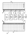
- FIG. 3 is a schematic diagram illustrating operation of an example of a system for locating sensors in a subsurface structure.
- FIG. 4 is a schematic diagram illustrating operation of another example of a system for locating sensors in a subsurface structure.
- FIG. 5 is a schematic diagram illustrating operation of another example of a system for locating sensors in a subsurface structure.
- FIG. 6A is a schematic diagram illustrating operation of an example method for measuring the distance to a sensor in an example system for locating sensors in a subsurface structure.
- FIG. 6B is a schematic diagram illustrating operation of another example method for measuring the distance to a sensor in an example system for locating sensors in a subsurface structure.
- Examples of the systems, methods, and apparatuses may be used in any subsurface structure in which sensors are embedded, or injected into the material of the structure or the material surrounding the structure.
- the description below refers to a well for petroleum or gas as an example of a subsurface structure in which advantageous use may be made of the examples described below. It is to be understood that the reference to wells or any other example structure is without limitation.
- the systems, methods and apparatuses may be used in structures other than wells, or any other specifically mentioned structure.
- Sensors of the types described below may be used to detect a variety of parameters relating to the material and environment surrounding the sensors when injected into the subsurface material.
- the sensors may be configured to measure variables such as temperature, pressure, pH, shear, salinity, and residence time. It is to be understood by those of ordinary skill in the arts that example variables are noted here without limitation.
- the sensors may be configured to measure any suitable variable whether or not it is mentioned.
- FIG. 1 is a block diagram of an example of a sensor 100 that may be used to collect data from subsurface structures.
- the sensor 100 may be a semiconductor or a “chip.”
- the sensor 100 may be a “nanoparticle” manufactured using nanotechnology to achieve ultra-miniature sizes for each sensor device.
- the sensor 100 may be used in a batch of many sensors 100 that is injected into the subsurface material, such as the rock surrounding a well.
- the batch of sensors 100 may be mixed in with water or other suitable fluid.
- the water is then pumped into the well and the pressure of the water pushes the sensors into the rock surrounding the well.
- the sensors 100 collect information once embedded in the rock structure.
- the sensors 100 are extracted by drawing the water out of the well.
- the sensors 100 are removed from the fluid and read to obtain the data collected by the individual sensors.
- the data can be read by either a RF wireless link or by probing small pads that are exposed on the sensor. If a RF wireless link is used the sensor will include an antenna and the associated electronics connected to the antenna that will drive it.
- the sensor 100 in FIG. 1 includes a controller 102 , a non-volatile memory 104 , a seismic signal sensing device 106 , a variable sensing device 108 , and a clock 110 .
- the controller 102 may be configured on the sensor 100 to provide processing functions, which may include administrative and maintenance functions for the sensors 100 as well as application-specific functions, such as functions for variable data gathering, storage and managing. Any suitable processor may be implemented; however, a small processing unit having processing capabilities closely scaled to the functional needs of the application may be most suitable as the application involves an environment of limited power, size and function.
- the non-volatile memory 104 may be provided for storage of data gathered by the individual sensor components on the sensor 100 as described in further detail below.
- the non-volatile memory 104 may also store identifying information (such as a serial number) and other administrative information that may be managed or used by the controller 102 .
- the seismic signal sensing device 106 may be any suitable sensing device or component for sensing a seismic wave.
- Example implementations use MEMS (“microelectromechanical systems”) technology for suitable sensors.
- the seismic signal sensing device 106 may be an accelerometer, a pressure sensor, or any other type of component that can sense seismic waves. Accelerometers may be constructed with a small proof mass that is suspended with flexible beams that allow the mass to move in one direction. The deflection of the mass may be measured capacitively or with piezo-resistors. Pressure sensors typically have small diaphragms with either a capacitive readout or piezo-resistor bridge to sense the deflections of the diaphragm.
- the seismic signal sensing device 106 may be configured to measure in three dimensions. For example, one or more accelerometers may be aligned with each of the three spatial axes. The measurements of the three groups of accelerometers may then be used to calculate the precise magnitude and direction of the seismic wave.
- the variable sensing device 108 may be any suitable sensor component configured to measure a variable relating to desired information about the environment surrounding the sensor 100 .
- the variable sensing device 108 may be a temperature sensor, a pressure sensor, a pH sensor, or any other type of sensor.
- the variable sensing device 108 is not included and the seismic signal sensing device 106 is used for detecting pressure or seismic activity in addition to detecting seismic wave signals for locating the sensor 100 as described below.
- the clock 110 may be a suitable processor clock for enabling the processing unit in the controller 102 to operate.
- the clock 110 may also include counting and timing functions for performing time-related functions as described below.
- the sensor 100 in FIG. 1 is shown in block diagram form; accordingly, a description of the physical structure of the sensor 100 is not provided.
- the sensor 100 may be configured in a manner that would permit the sensor 100 to fit in the openings of porous rock or other subsurface material.
- the sensor 100 may have a round shape, or configured with a shape that reduces the likelihood that the sensors 100 will get stuck in cracks in the formation.
- the sensors 100 may be passivated, such as for example, by coating the sensors 100 with a coating (such as for example, an epoxy coating) that protects the sensors 100 from elements in the environment of the formation that may have a destructive effect on the sensors 100 .
- a coating such as for example, an epoxy coating
- Such elements include, for example, certain fluids, pH, abrasion, and heat.
- the passivation may accommodate a portal, or some other form of access for measurement of sensor parameters.
- the sensors 100 are injected into the subsurface material and systems, methods and apparatuses consistent with examples described below may be used to determine their location in the material when the sensors 100 gather their data.
- the sensor 100 may be provided with a power source, which may be a battery.
- the power source may be connected to a circuit that maintains the power in an ‘off’ or low power state.
- the power may be turned to an ‘on’ state when the sensor 100 initially detects a seismic wave signal.
- FIG. 2 is a schematic diagram of an example of a system 200 for locating sensors in a subsurface structure.
- the system 200 in FIG. 2 includes a sensor location apparatus 202 disposed inside a well 204 supported by a well casing 206 .
- the well casing 206 may be perforated with multiple casing openings 207 in selected regions where the sensors 100 will move into the formation material 204 ′.
- the multiple casing openings 207 are shown as distributed throughout the casing 206 in FIGS. 2-5 , however, the multiple casing openings 207 may be distributed selectively depending on where the sensors 100 are to be dispersed.
- the well 204 is a substantially cylindrical opening into well formation material 204 ′.
- the sensor location apparatus 202 includes a locating apparatus controller 210 , and at least one seismic signal generator 212 .
- the system 200 in FIG. 2 depicts the example sensor location apparatus 202 as having 3 seismic signal generators 212 a , 212 b , and 212 c . Any suitable number seismic signal generators 212 may be implemented.
- the sensor location apparatus 202 may include structure for descending the sensor location apparatus 202 into the well 204 .
- the function of lowering the sensor location apparatus 202 may involve an attached cable, rope, pipe, or other device for suspending the sensor location apparatus 202 during the descent of the sensor location apparatus 202 into the well 204 using methods well known to the industry.
- the depth of each seismic signal generator 212 is monitored and recorded each time the seismic signal generator 212 performs measurement functions. The monitoring of the depths may be performed by the sensor location apparatus controller 210 , or by each seismic signal generator 212 .
- the sensor location apparatus 202 may include an enclosure for the sensor location apparatus controller 210 and the at least one seismic signal generator 212 a - c , or for the at least one seismic signal generator 212 a - c .
- the enclosure may be sealed sufficiently to keep moisture away from the at least one seismic signal generator 212 a - c for applications in which the sensor location apparatus 202 is to be submerged in water or other fluid in the well 204 .
- the sensor location apparatus 202 is lowered into the well 204 after a batch of sensors 100 (in FIG. 1 ) has been injected into the well formation material 204 ′.
- the fluid used to inject the sensors 100 into the well formation material 204 ′ may still be in the well 204 when the sensor location apparatus 202 is used.
- the sensor location apparatus controller 210 provides control over the function of locating the sensors 100 by controlling the seismic signal generators 212 .
- the sensor location apparatus controller 210 includes hardware and software components that control the seismic signal generators 212 to generate seismic signals at predetermined times or depths as the sensor location apparatus 202 proceeds downward through the well 204 .
- Each of the three seismic signal generators 212 a - c in FIG. 2 include a seismic signal conduction path 214 a - c used by each seismic signal generator 212 a - c to transmit seismic signals into the well formation material 204 ′.
- the seismic signal generators 212 a - c may be configured to generate seismic wave signals to communicate an identifier that may subsequently be used by the sensor 100 that receives the identifier to determine the depth at which the identifier was transmitted.
- the seismic wave signals may also be used to enable the sensor 100 to determine the distance between the sensor location apparatus 202 and the sensor 100 . Examples of the use of an identifier and of the determination of the distance to the sensor 100 are discussed below with reference to FIGS. 6A and 6B .
- the seismic signal generators 212 a - c may generate the seismic signals based on coding information, which may be communicated from the sensor location apparatus controller 210 or managed by the individual seismic signal generator 212 a - c .
- the coding information may include a correspondence between the identifier and a depth at which the seismic wave signal was transmitted.
- the seismic wave signal transmitted by the seismic signal generators 212 a - c may be modulated to include the coding information.
- the coding information may then be extracted by the sensors 100 by demodulating the seismic wave signal.
- the coding information may include any suitable information.
- the coding information includes an identifier that may be used to determine the depth in the well 204 at which the seismic wave signal was transmitted. This depth would correspond at least approximately to the depth of the sensor or sensors 100 in the well formation material 204 ′ that received the seismic wave signal.
- the depth information would then be stored in the non-volatile memory 104 along with any variables measured at that time.
- the seismic signal generators 212 a - c may also generate any other coded, or uncoded, seismic wave signals for any other function that includes communicating with the sensors 100 .
- the seismic signal generators 212 a - c may transmit a seismic wave signal having both p-wave and s-wave components.
- the p-wave and s-wave components are elastic seismic waves that may be generated to propagate in the subsurface.
- the p-waves are formed from alternating compressions and rarefactions.
- the s-waves are elastic waves that move in a direction that is perpendicular to the direction of the wave as a shear or transverse motion.
- the velocity of the p-waves is about twice the velocity of the s-waves. This difference in velocity allows the sensor 100 to calculate the distance between the seismic signal generator 212 and the sensor 100 .
- the sensor 100 detects the p-wave, the sensor begins a timer, which is triggered to stop when the sensor 100 detects the s-wave.
- the calculated distance d would then be stored in the non-volatile memory 104 , along with any variables measured at that time.
- FIG. 2 shows a cross-sectional view of the well 204 with the well formation material 204 ′ that surrounds the well 204 shown on opposite sides of the well 204 .
- the well 204 being a substantially cylindrical opening has well formation material 204 ′ surrounding the opening.
- the sensors injected into the well formation material 204 ′ would move through the material surrounding the well 204 .
- the seismic signal generators 212 a - c may be configured to turn radially to provide more direct signal paths into the well formation material 204 ′ completely surrounding the well 204 .
- the seismic generators 212 a - c and associated signal conduction paths 214 a - c can be positioned circumferentially, projecting the signal in different radial directions, on the signal location apparatus 202 so that there is no need to rotate the apparatus.
- FIG. 3 is a schematic diagram illustrating operation of an example of a system 300 for locating sensors 320 in a subsurface structure.
- the system 300 shown in FIG. 3 includes a sensor location apparatus 302 being lowered into a well 304 formed in a well formation material 304 ′ and supported by a casing 306 .
- the sensor location apparatus 302 includes a controller 310 and three seismic signal generators 312 a - c , which include signal conduction paths 314 a - c .
- FIG. 3 also shows the sensors 320 after having been injected into the well formation material 304 ′.
- the sensor location apparatus 302 is being lowered into the well 304 .
- the seismic signal generators 312 a - c transmit seismic wave signals into the well formation material 304 ′.
- the seismic wave signals are transmitted by the seismic signal generators 312 a - c at different times.
- a first seismic wave signal 350 is transmitted first.
- a second seismic wave signal 352 is transmitted.
- a third seismic wave signal 354 is transmitted.
- the known time intervals and the measurement of the time of the conduction of the transmitted signals may be used to determine the location of the sensors 320 .
- the seismic signal generators 312 a - c may be programmed to transmit seismic wave signals in a sequence separated by predetermined, fixed time intervals.
- Sensor 320 ′ in FIG. 3 is receiving the first seismic wave signal 350 transmitted by the first seismic signal generator 312 a .
- the sensor 320 ′ may determine the elapsed time from the receipt of the p-wave to the receipt of the s-wave in the first seismic wave signal 350 and identify the time as the first s-wave time, t s1 .
- the sensor 320 ′ may also then receive the second seismic wave signal 352 from the second seismic signal generator 312 b .
- the sensor 320 ′ may determine the elapsed time from the receipt of the p-wave of the second seismic wave signal 352 to the s-wave, and identify the time as the second s-wave time, t s2 .
- the time between the transmission of the first seismic wave signal 350 and the transmission of the second seismic wave signal 352 is known, allowing the sensor 302 ′ to distinguish the two seismic wave signals 350 , 352 while measuring the s-wave times.
- the velocity of the first and second seismic wave signals 350 , 352 is also known.
- the distance between the ends of the signal conduction paths 314 a and 314 b are also known at the times of the signal transmissions. The difference between t s1 and t s2 may then be used in a triangulation to determine the precise location of the sensor 320 ′.
- FIG. 4 is a schematic diagram illustrating operation of another example of a system 400 for locating sensors in a subsurface structure.
- the system 400 shown in FIG. 4 includes a sensor location apparatus 402 being lowered into a well 404 formed in a well formation material 404 ′ and supported by a casing 406 .
- the sensor location apparatus 402 includes a controller 410 and three seismic signal generators 412 a - c , which include signal conduction paths 414 a - c .
- FIG. 4 also shows the sensors 420 after having been injected into the well formation material 404 ′.
- the seismic signal generators 412 a - c transmit seismic wave signals into the well formation material 404 ′.
- the seismic wave signals transmitted by the seismic signal generators 312 a - c have different characteristics.
- the seismic signal generators 412 a - c may transmit seismic wave signals have different frequencies (indicated in FIG. 4 by the different line shading for each signal).
- a first seismic wave signal 450 is transmitted having a first frequency.
- a second seismic wave signal 452 is transmitted at a second frequency, and a third seismic wave signal 454 is transmitted at a third frequency.
- the use of different frequencies for each seismic wave signal 450 , 452 , 454 allows the sensors 420 to distinguish the signals.
- the known differences in the frequencies of the seismic wave signals 450 , 452 , 454 and the measurement of the time of the conduction of the transmitted signals may be used to determine the location of the sensors 420 .
- the seismic signal generators 412 a - c may be programmed to transmit seismic wave signals 450 , 452 , 454 either sequentially or at the same time.
- a sensor 420 ′ in FIG. 4 is receiving the first seismic wave signal 450 transmitted by the first seismic signal generator 412 a .
- the sensor 420 ′ may determine the elapsed time from the receipt of the p-wave to the receipt of the s-wave in the first seismic wave signal 450 and identify the time as the first s-wave time, t s1 .
- the sensor 420 ′ may also receive the second seismic wave signal 452 from the second seismic signal generator 412 b .
- the sensor 420 ′ may determine the elapsed time from the receipt of the p-wave of the second seismic wave signal 452 to the s-wave, and identify the time as the second s-wave time, t s2 .
- the difference in frequencies of the first and second seismic wave signals 450 , 452 allows the sensor 420 ′ to distinguish between the two signals while measuring the s-wave times.
- the velocity of the first and second seismic wave signals 450 , 452 is known.
- the distance between the ends of the signal conduction paths 414 a and 414 b are also know at the times of the signal transmissions.
- the difference between t s1 and t s2 may then be used in a triangulation to determine the precise location of the sensor 420 ′.
- FIG. 5 is a schematic diagram illustrating operation of another example of a system 500 for locating sensors in a subsurface structure.
- the system 500 in FIG. 5 includes a sensor location apparatus 502 having a controller 510 and a seismic signal generator 512 .
- the sensor location apparatus 502 is lowered into a well 504 formed into a well formation material 504 ′ supported by a well casing 506 .
- the controller 510 in the sensor location apparatus 502 may monitor the descent of the sensor location apparatus 502 and provide program control that controls the seismic signal generator 512 during the descent.
- the seismic signal generator 512 may transmit seismic wave signals 550 , 552 into the well formation material 504 ′ using a signal conduction path 514 .
- the seismic wave signals 550 , 552 may be transmitted at selected depths of the well 502 .
- the seismic wave signals 550 , 552 may include a first signal 550 having an identifier corresponding to a known depth in the well 502 at which the first signal 550 is transmitted.
- the seismic wave signals 552 may also include a second signal 552 having a p-wave and an s-wave component as described above with reference to FIG. 2 .
- the p-wave and s-wave may be used to determine the distance between the sensor 520 and the seismic signal generator 512 as described above with reference to FIG. 2 and in more detail below with reference to FIGS. 6A and 6B .
- FIG. 6A is a schematic diagram illustrating operation of an example method 600 for measuring the distance to a sensor in an example system for locating sensors in a subsurface structure.
- the method in FIG. 6A depicts an example sensor location apparatus 602 , which in operation descends into a well as indicated by downward arrow A.
- the sensor location apparatus 602 controls one or more seismic signal generators (for example, signal generator 512 in FIG. 5 ) to generate seismic wave signals in two steps.
- the seismic signal generator transmits a first identifier wave 614 .
- a distance measurement wave signal is generated.
- the distance measurement wave signal includes a p-wave component 616 and an s-wave component 618 .
- the first identifier wave 614 and the distance measurement wave signal may be sensed by a sensor in the well formation material.
- the seismic signal generator performs another first step 621 of generating a second identifier wave 624 .
- a distance measurement wave signal may be transmitted at step 622 .
- FIG. 6A shows sensor 620 receiving the second identifier wave 624 and a p-wave 626 and s-wave 628 in the distance measurement wave signal.
- the sensor 620 receives the p-wave 626 and may begin a timer to measure the time elapsed until the sensor 620 receives the s-wave 628 as shown at 650 .
- the elapsed s-wave time, t s is used as described above with reference to FIG. 2 and Equation (1) to determine the distance from the signal source (the seismic signal generator) and the sensor 620 .
- the sensor location apparatus 602 may continue the control of the transmission of the seismic waves during its descent at selected depths.
- an n-th distance measurement wave signal including a p-wave 636 and an s-wave 638 .
- the sensor 620 determines the depth of the location of the sensor 620 in the well based on the correlation of the depth with the identifier corresponding to the code modulated into the identifier wave 614 , 624 , 634 .
- the sensor 620 determines its distance from the signal generator using elapsed time, t s .
- the location of the sensor 620 relative to the opening of the well may be determined in terms of the depth of the sensor location apparatus 602 and the distance to the signal generator.
- the method 600 may make use of a single seismic signal generator as shown in the system 500 in FIG. 5 .
- the seismic signal generator 512 may transmit the signals of the first and second steps shown in FIG. 6 at each of selected depths D.
- the method 600 may also make use of multiple seismic signal generators, such as the system 200 shown in FIG. 2 .
- Each seismic signal generator 212 a - c in FIG. 2 may transmit the seismic wave signals of the two steps and each seismic signal generator 212 a - c would be at one of the selected depths D.
- the method 600 assumes that the identifier wave 614 , 624 , 634 moves substantially horizontally and that the volume of well formation material affected by the wave can be limited. While both conditions may be controlled, another example implementation makes use of waves propagating in a larger volume and having the sensors 620 make use of multiple signal receptions.
- FIG. 6B is a schematic diagram illustrating operation of another example method 660 for measuring the distance to the sensor 620 in an example system for locating sensors in a subsurface structure.
- FIG. 6B shows the sensor location apparatus 602 in descent similar to the illustration in FIG. 6A .
- the seismic signal generator(s) transmit the seismic wave signals through expanded volumes of well formation material.
- a first step 610 transmits a first identifier wave as described above with reference to FIG. 6A .
- a distance measurement wave is transmitted with a p-wave and s-wave as described above with reference to FIG. 6A .
- the two waves are shown in FIG. 6B combined as vector 670 , which depicts the path of the wave directly to the sensor 620 .
- a second identifier wave is transmitted by the seismic signal generator.
- a second distance measurement signal is transmitted.
- the second identifier wave and the second distance measurement signal are shown in FIG. 6B combined as vector 672 , which depicts the path of the wave directly to the sensor 620 at a different depth.
- the sensor 620 may be configured to distinguish the seismic wave signals in vector 670 from the seismic wave signals in vector 672 . The distinction may be indicated in a variety of ways, including but not limited to:
- Elapsed s-wave times, t 1 and t 2 may be measured for vectors 670 and 672 , respectively.
- the elapsed s-wave times, t 1 and t 2 may be used to determine the precise depth of sensor 620 between depth D 1 and D 2 , and the lateral distance to the sensor 620 from the seismic signal generator in the well using triangulation as described above with reference to FIG. 4 .
- Example embodiments provided in accordance with the presently disclosed subject matter include, but are not limited to, the following:
- a system for determining the location of sensors embedded in material surrounding a well comprising:
- the seismic wave signal includes a modulated seismic wave signal configured to communicate an identifier corresponding to a depth of the seismic signal generator that transmitted the seismic wave signal.
- seismic wave signal includes a seismic wave signal having a p-wave or an s-wave component.
- invention A6 The system of embodiment A further comprising at least one additional seismic signal generator, where the at least one seismic signal generator and the at least one additional seismic signal generator are aligned vertically along a path of descent into the well at fixed distances from one another.
- each seismic signal generator is configured to generate seismic wave signals at a frequency that is different from the frequency used by the other seismic signal generators.
- each seismic signal generator is configured to generate seismic wave signals repeatedly with a time delay between each generation of seismic wave signals where each seismic signal generator generates the seismic wave signals by controlling the time delay to either be different from the time delay used by the other seismic signal generators, or fixed between the signals generated by the multiple seismic signal generators.
- the system of embodiment A where the at least one seismic signal generator comprises a plurality of signal conduction paths positioned radially around the seismic signal generator to transmit seismic wave signals at different angles without rotating.
- a method for gathering data relating to a subsurface material surrounding a well comprising:
- the method of embodiment B1 where the step of storing includes determining a direction of travel for the seismic wave signal.
- the method of embodiment B3 where the step of storing includes determining a direction of travel for the seismic wave signal.
- each of the seismic signal generators generates the seismic wave signals repeatedly with either a time delay between seismic wave signal generations that is different than the other seismic signal generators, or a time delay that is fixed between the signals generated by the multiple seismic signal generators.
- a method for determining the location of a plurality of sensors embedded in a subsurface material surrounding a well comprising:
- the method of embodiment C1 where the step of storing includes determining a direction of travel for the seismic wave signal.
- the method of embodiment C3 where the step of storing includes determining a direction of travel for the seismic wave signal.
- a sensor for detecting variable conditions in a subsurface material surrounding a well the sensor having a size small enough to travel into the subsurface material, the sensor comprising:
- the sensor of embodiment D where the seismic signal sensing device is configured to detect a p-wave and an s-wave in the seismic signal, and to determine an elapse time between receipt of the p-wave and receipt of the s-wave.
Landscapes
- Engineering & Computer Science (AREA)
- Physics & Mathematics (AREA)
- Life Sciences & Earth Sciences (AREA)
- Mining & Mineral Resources (AREA)
- Geology (AREA)
- Environmental & Geological Engineering (AREA)
- Geophysics (AREA)
- Fluid Mechanics (AREA)
- General Life Sciences & Earth Sciences (AREA)
- Geochemistry & Mineralogy (AREA)
- Remote Sensing (AREA)
- Electromagnetism (AREA)
- Geophysics And Detection Of Objects (AREA)
Abstract
Description
d=(V p −V s)×T, Eqn. (1)
-
- where, Vp=p-wave velocity, and Vs=s-wave velocity,
- T=time elapsed between detecting p-wave and detecting s-wave.
- where, Vp=p-wave velocity, and Vs=s-wave velocity,
-
- 1. Transmission of different identification codes between
vectors - 2. Transmission of the first wave (vector 670) at a predetermined time interval prior to transmission of the second wave (vector 672) (as described above with reference to
FIG. 3 ). - 3. Transmission of seismic wave signals (670 and 672) having different characteristics, such as, different frequencies (as described above with reference to
FIG. 4 ).
- 1. Transmission of different identification codes between
-
- at least one seismic signal generator configured to generate a seismic wave signal to communicate information to enable determination of the sensor location to the sensor;
- a sensor location apparatus configured to lower the at least one seismic signal generator into the subsurface structure; and
- a sensor location controller configured to actuate generation of the seismic wave signal as the at least one seismic signal generator is lowered into the well.
-
- pumping a fluid having a plurality of sensors into the well, the sensors configured to travel into the subsurface material assisted by a force imparted by the fluid;
- lowering a seismic signal generator into the well;
- at selected depths, transmitting a seismic wave signal into the subsurface material surrounding the well, where the seismic wave signal is configured to communicate information to enable determination of the location of the sensor that receives the seismic wave signal;
- for each sensor that received the seismic wave signal, storing the information at the sensor;
- measuring a variable characteristic about the subsurface material at each sensor;
- extracting the fluid and the sensors from the well; and
- using the information on each sensor to determine the location of the sensor.
-
- the step of transmitting the seismic wave signal includes modulating the seismic wave signal to carry an identifier corresponding to a current depth of the seismic signal generator;
- the step of storing includes demodulating the seismic wave signal to determine the identifier and storing the identifier in the sensor.
-
- the step of transmitting the seismic wave signal includes generating the seismic wave signal with a p-wave and an s-wave;
- the step of storing includes determining an elapsed time between p-wave and s-wave by performing the steps of:
- detecting the p-wave at the sensor;
- starting a timer when p-wave is detected;
- detecting the s-wave at the sensor;
- stopping the timer when the s-wave is detected; and
- storing the elapsed time between p-wave and s-wave detection.
-
- the step of transmitting the seismic wave signal includes modulating the seismic wave signal to carry an identifier corresponding to a current depth of the seismic signal generator;
- the step of storing for each sensor that received the seismic wave signal includes:
- demodulating the seismic wave signal to determine the identifier and storing the identifier in the sensor;
- comparing the identifier for the seismic wave signal with a previously stored identifier for a previously received seismic wave signal;
- if the identifier is different from the previously stored identifier:
- storing the identifier as a second identifier in the sensor;
- performing the steps of determining the elapsed time between the p-wave and the s-wave and storing the elapsed time as a second elapsed time corresponding to the second identifier;
- the step of using the information on each sensor includes:
- for each sensor that stored more than one identifier, detecting the sensor location by performing a triangulation using a depth corresponding to each identifier stored in the sensor, the elapsed times corresponding to each identifier, the direction of each seismic wave signal, and the velocity of seismic waves in the subsurface material surrounding the well.
-
- turning power on in each sensor that receives the seismic wave signal upon receipt of the seismic wave signal.
-
- lowering at least one additional seismic signal generator such that the multiple seismic signal generators extend vertically in the well at fixed distances from one another.
-
- lowering at least one seismic signal generator into the well;
- at selected depths, transmitting a seismic wave signal into the subsurface material surrounding the well, where the seismic wave signal is configured to communicate information to enable determination of the location of the sensor that receives the seismic wave signal;
- extracting the fluid and the sensors from the well; and
- using the information on each sensor to determine the location of the sensor.
-
- the step of transmitting the seismic wave signal includes modulating the seismic wave signal to carry an identifier corresponding to a current depth of the seismic signal generator;
- the step of storing includes demodulating the seismic wave signal to determine the identifier and storing the identifier in the sensor.
-
- the step of transmitting the seismic wave signal includes generating the seismic wave signal with a p-wave and an s-wave;
- the step of storing includes determining an elapsed time between p-wave and s-wave by performing the steps of:
- detecting the p-wave at the sensor;
- starting a timer when p-wave is detected;
- detecting the s-wave at the sensor;
- stopping the timer when the s-wave is detected; and
- storing the elapsed time between p-wave and s-wave detection.
-
- the step of transmitting the seismic wave signal includes modulating the seismic wave signal to carry an identifier corresponding to a current depth of the seismic signal generator;
- the step of storing for each sensor that received the seismic wave signal includes:
- demodulating the seismic wave signal to determine the identifier and storing the identifier in the sensor;
- comparing the identifier for the seismic wave signal with a previously stored identifier for a previously received seismic wave signal;
- if the identifier is different from the previously stored identifier:
- storing the identifier as a second identifier in the sensor;
- performing the steps of determining the elapsed time between the p-wave and the s-wave and storing the elapsed time as a second elapsed time corresponding to the second identifier;
- the step of using the information on each sensor includes:
- for each sensor that stored more than one identifier, detecting the sensor location by performing a triangulation using a depth corresponding to each identifier stored in the sensor, the elapsed times corresponding to each identifier, the direction of each seismic wave signal, and the velocity of p-waves in the subsurface material surrounding the well.
-
- turning power on in each sensor that receives the seismic wave signal upon receipt of the seismic wave signal.
-
- a controller;
- a memory component for storing information;
- a seismic signal sensing device configured to detect a seismic signal and connected to provide a sensor signal corresponding to the detected seismic signal to the controller; and
- where the controller is configured to extract information for determining the location of the sensor from the detected seismic signal and to store the information in the memory component.
Claims (17)
Priority Applications (1)
| Application Number | Priority Date | Filing Date | Title |
|---|---|---|---|
| US14/417,674 US10125599B2 (en) | 2012-08-02 | 2013-08-01 | Location of sensors in well formations |
Applications Claiming Priority (3)
| Application Number | Priority Date | Filing Date | Title |
|---|---|---|---|
| US201261678793P | 2012-08-02 | 2012-08-02 | |
| PCT/US2013/053291 WO2014022705A1 (en) | 2012-08-02 | 2013-08-01 | Location of sensors in well formations |
| US14/417,674 US10125599B2 (en) | 2012-08-02 | 2013-08-01 | Location of sensors in well formations |
Publications (2)
| Publication Number | Publication Date |
|---|---|
| US20150211358A1 US20150211358A1 (en) | 2015-07-30 |
| US10125599B2 true US10125599B2 (en) | 2018-11-13 |
Family
ID=50028543
Family Applications (1)
| Application Number | Title | Priority Date | Filing Date |
|---|---|---|---|
| US14/417,674 Active 2035-06-02 US10125599B2 (en) | 2012-08-02 | 2013-08-01 | Location of sensors in well formations |
Country Status (4)
| Country | Link |
|---|---|
| US (1) | US10125599B2 (en) |
| EP (1) | EP2880466B1 (en) |
| CA (1) | CA2880259C (en) |
| WO (1) | WO2014022705A1 (en) |
Families Citing this family (3)
| Publication number | Priority date | Publication date | Assignee | Title |
|---|---|---|---|---|
| US10139506B2 (en) | 2014-03-14 | 2018-11-27 | Bp Exploration Operating Company Limited | Seismic sensor |
| CA3080372C (en) | 2015-03-06 | 2022-07-26 | Halliburton Energy Services, Inc. | Optimizing sensor selection and operation for well monitoring and control |
| US10209175B2 (en) | 2015-07-31 | 2019-02-19 | Micross Advanced Interconnect Technology Llc | Detection of corrosion using dispersed embedded sensors |
Citations (22)
| Publication number | Priority date | Publication date | Assignee | Title |
|---|---|---|---|---|
| US4783771A (en) | 1986-03-18 | 1988-11-08 | Chevron Research Company | Nondestructive downhole seismic vibrator source and processes of utilizing the vibrator to obtain information about geologic formations |
| US5113996A (en) | 1990-03-07 | 1992-05-19 | Cavanna S.P.A. | Rotary multiple point discharge conveyer |
| US5248857A (en) * | 1990-04-27 | 1993-09-28 | Compagnie Generale De Geophysique | Apparatus for the acquisition of a seismic signal transmitted by a rotating drill bit |
| US5924049A (en) * | 1995-04-18 | 1999-07-13 | Western Atlas International, Inc. | Methods for acquiring and processing seismic data |
| US20030026166A1 (en) | 2000-07-21 | 2003-02-06 | Baker Hughes Incorporated | Use of minor borehole obstructions as seismic sources |
| US20030043055A1 (en) | 1999-04-23 | 2003-03-06 | Schultz Roger L. | Self-contained downhole sensor and method of placing and interrogating same |
| US20040076077A1 (en) * | 2001-01-25 | 2004-04-22 | Johan Robertsson | Method of processing marine seismic data and a method of seismic surveying |
| US20060062084A1 (en) * | 2004-09-17 | 2006-03-23 | Julian Drew | Microseismic event detection and location by continuous map migration |
| US20060209635A1 (en) * | 2005-03-18 | 2006-09-21 | Halliburton Energy Services, Inc. | Controlled source imbalance apparatus, systems, and methods |
| US20080106973A1 (en) * | 2006-11-06 | 2008-05-08 | Magnitude Spas | Memory seismic device and method |
| US20080149329A1 (en) * | 2006-12-20 | 2008-06-26 | Iain Cooper | Real-Time Automated Heterogeneous Proppant Placement |
| US20080159075A1 (en) * | 2006-12-28 | 2008-07-03 | Underhill William B | Technique and system for performing a cross well survey |
| US7424928B2 (en) * | 2005-09-13 | 2008-09-16 | Dale Cox | Apparatus, system and method for flexibly coupling sensors to a downhole tool |
| US20090242205A1 (en) * | 2008-03-26 | 2009-10-01 | Schlumberger Technology Corporation | Method and apparatus for detecting acoustic activity in a subsurface formation |
| US20090299637A1 (en) * | 2005-11-03 | 2009-12-03 | Dasgupta Shivaji N | Continuous Reservoir Monitoring for Fluid Pathways Using Microseismic Data |
| US20090326895A1 (en) * | 2008-06-30 | 2009-12-31 | Beasley Craig J | Technique and system for seismic source separation |
| US20100268470A1 (en) | 2009-03-13 | 2010-10-21 | Saudi Arabian Oil Company | System, Method, and Nanorobot to Explore Subterranean Geophysical Formations |
| US20110176383A1 (en) * | 2010-01-19 | 2011-07-21 | Fairfield Industries Incorporated | Method and apparatus for accurate placement of ocean bottom seismic instrumentation |
| WO2011109014A1 (en) | 2010-03-02 | 2011-09-09 | David John Kusko | Borehole flow modulator and inverted seismic source generating system |
| US8226328B2 (en) * | 2008-09-03 | 2012-07-24 | Fairfield Industries Incorporated | Seismic cable with adjustable buoyancy |
| US20120250455A1 (en) * | 2011-03-29 | 2012-10-04 | Djikpesse Hugues A | Selecting a survey setting for characterizing a target structure |
| US20120273192A1 (en) * | 2011-04-26 | 2012-11-01 | Saudi Arabian Oil Company | Hybrid Transponder System For Long-Range Sensing and 3D Localization |
Family Cites Families (1)
| Publication number | Priority date | Publication date | Assignee | Title |
|---|---|---|---|---|
| US5113966A (en) * | 1990-04-19 | 1992-05-19 | The United States Of America As Represented By The United States Department Of Energy | Downhole hydraulic seismic generator |
-
2013
- 2013-08-01 EP EP13825224.2A patent/EP2880466B1/en active Active
- 2013-08-01 US US14/417,674 patent/US10125599B2/en active Active
- 2013-08-01 CA CA2880259A patent/CA2880259C/en active Active
- 2013-08-01 WO PCT/US2013/053291 patent/WO2014022705A1/en active Application Filing
Patent Citations (26)
| Publication number | Priority date | Publication date | Assignee | Title |
|---|---|---|---|---|
| US4783771A (en) | 1986-03-18 | 1988-11-08 | Chevron Research Company | Nondestructive downhole seismic vibrator source and processes of utilizing the vibrator to obtain information about geologic formations |
| US5113996A (en) | 1990-03-07 | 1992-05-19 | Cavanna S.P.A. | Rotary multiple point discharge conveyer |
| US5248857A (en) * | 1990-04-27 | 1993-09-28 | Compagnie Generale De Geophysique | Apparatus for the acquisition of a seismic signal transmitted by a rotating drill bit |
| US5924049A (en) * | 1995-04-18 | 1999-07-13 | Western Atlas International, Inc. | Methods for acquiring and processing seismic data |
| US20030043055A1 (en) | 1999-04-23 | 2003-03-06 | Schultz Roger L. | Self-contained downhole sensor and method of placing and interrogating same |
| US20030026166A1 (en) | 2000-07-21 | 2003-02-06 | Baker Hughes Incorporated | Use of minor borehole obstructions as seismic sources |
| US20040076077A1 (en) * | 2001-01-25 | 2004-04-22 | Johan Robertsson | Method of processing marine seismic data and a method of seismic surveying |
| US20060062084A1 (en) * | 2004-09-17 | 2006-03-23 | Julian Drew | Microseismic event detection and location by continuous map migration |
| US20060209635A1 (en) * | 2005-03-18 | 2006-09-21 | Halliburton Energy Services, Inc. | Controlled source imbalance apparatus, systems, and methods |
| US7424928B2 (en) * | 2005-09-13 | 2008-09-16 | Dale Cox | Apparatus, system and method for flexibly coupling sensors to a downhole tool |
| US20090299637A1 (en) * | 2005-11-03 | 2009-12-03 | Dasgupta Shivaji N | Continuous Reservoir Monitoring for Fluid Pathways Using Microseismic Data |
| US20080106973A1 (en) * | 2006-11-06 | 2008-05-08 | Magnitude Spas | Memory seismic device and method |
| US20080149329A1 (en) * | 2006-12-20 | 2008-06-26 | Iain Cooper | Real-Time Automated Heterogeneous Proppant Placement |
| WO2008081373A2 (en) | 2006-12-28 | 2008-07-10 | Schlumberger Canada Limited | Technique and system for performing a cross well survey |
| US20080159075A1 (en) * | 2006-12-28 | 2008-07-03 | Underhill William B | Technique and system for performing a cross well survey |
| US8107317B2 (en) * | 2006-12-28 | 2012-01-31 | Schlumberger Technology Corporation | Technique and system for performing a cross well survey |
| US20120127827A1 (en) * | 2006-12-28 | 2012-05-24 | Schlumberger Technology Corporation | Technique and system for performing a cross well survey |
| US9310505B2 (en) * | 2006-12-28 | 2016-04-12 | Schlumberger Technology Corporation | Technique and system for performing a cross well survey |
| US20090242205A1 (en) * | 2008-03-26 | 2009-10-01 | Schlumberger Technology Corporation | Method and apparatus for detecting acoustic activity in a subsurface formation |
| US20090326895A1 (en) * | 2008-06-30 | 2009-12-31 | Beasley Craig J | Technique and system for seismic source separation |
| US8226328B2 (en) * | 2008-09-03 | 2012-07-24 | Fairfield Industries Incorporated | Seismic cable with adjustable buoyancy |
| US20100268470A1 (en) | 2009-03-13 | 2010-10-21 | Saudi Arabian Oil Company | System, Method, and Nanorobot to Explore Subterranean Geophysical Formations |
| US20110176383A1 (en) * | 2010-01-19 | 2011-07-21 | Fairfield Industries Incorporated | Method and apparatus for accurate placement of ocean bottom seismic instrumentation |
| WO2011109014A1 (en) | 2010-03-02 | 2011-09-09 | David John Kusko | Borehole flow modulator and inverted seismic source generating system |
| US20120250455A1 (en) * | 2011-03-29 | 2012-10-04 | Djikpesse Hugues A | Selecting a survey setting for characterizing a target structure |
| US20120273192A1 (en) * | 2011-04-26 | 2012-11-01 | Saudi Arabian Oil Company | Hybrid Transponder System For Long-Range Sensing and 3D Localization |
Non-Patent Citations (3)
| Title |
|---|
| European Examination Report dated Jul. 24, 2017 from related European Application No. 13825224.2. |
| European Search Report and Written Opinion dated Jun. 17, 2016 from related European Application No. 13825224.2. |
| International Search Report and Written Opinion dated Oct. 24, 2013 for PCT/US2013/053291. |
Also Published As
| Publication number | Publication date |
|---|---|
| US20150211358A1 (en) | 2015-07-30 |
| CA2880259A1 (en) | 2014-02-06 |
| CA2880259C (en) | 2021-03-02 |
| EP2880466A4 (en) | 2016-07-20 |
| WO2014022705A1 (en) | 2014-02-06 |
| EP2880466B1 (en) | 2018-09-19 |
| EP2880466A1 (en) | 2015-06-10 |
Similar Documents
| Publication | Publication Date | Title |
|---|---|---|
| CA2875719C (en) | Microseismic monitoring with fiber-optic noise mapping | |
| AU2011281359B2 (en) | Communication through an enclosure of a line | |
| EP2748424B1 (en) | Determining perforation orientation | |
| US20170335678A1 (en) | Smart frac plug | |
| BR112018011424B1 (en) | SYSTEM AND METHOD FOR ACOUSTIC DETECTION AND COMMUNICATION | |
| US20060081412A1 (en) | System and method for combined microseismic and tiltmeter analysis | |
| CN106461806A (en) | Method and system for downhole object location and orientation determination | |
| WO2018236752A1 (en) | Simultaneous interference testing and fracturing testing | |
| US10125599B2 (en) | Location of sensors in well formations | |
| WO2014058745A2 (en) | System and method for monitoring fracture treatment using optical fiber sensors in monitor wellbores | |
| CA3119615C (en) | A sensor system for detecting fiber optic cable locations and performing flow monitoring downhole | |
| US20220206172A1 (en) | Global Positioning System Encoding On A Data Stream | |
| Wang et al. | Hydraulic fracture monitoring using distributed acoustic sensing: A case study using dip-in fiber | |
| RU2480583C1 (en) | Telemetric system of bottomhole parameters monitoring | |
| WO2016010447A1 (en) | A borehole sensing seismic fiber optic tool |
Legal Events
| Date | Code | Title | Description |
|---|---|---|---|
| AS | Assignment |
Owner name: RESEARCH TRIANGLE INSTITUTE, NORTH CAROLINA Free format text: ASSIGNMENT OF ASSIGNORS INTEREST;ASSIGNOR:GOODWIN, SCOTT;REEL/FRAME:034826/0739 Effective date: 20150115 |
|
| AS | Assignment |
Owner name: ALLY BANK, NEW YORK Free format text: GRANT OF SECURITY INTEREST IN PATENTS;ASSIGNOR:MICROSS ADVANCED INTERCONNECT TECHNOLOGY LLC;REEL/FRAME:040229/0512 Effective date: 20161003 |
|
| AS | Assignment |
Owner name: MICROSS ADVANCED INTERCONNECT TECHNOLOGY LLC, NORT Free format text: ASSIGNMENT OF ASSIGNORS INTEREST;ASSIGNOR:RESEARCH TRIANGLE INSTITUTE;REEL/FRAME:040387/0745 Effective date: 20161003 |
|
| AS | Assignment |
Owner name: MIDCAP FINANCIAL TRUST, MARYLAND Free format text: SECURITY INTEREST;ASSIGNOR:MICROSS ADVANCED INTERCONNECT TECHNOLOGY LLC;REEL/FRAME:043476/0302 Effective date: 20170807 Owner name: MICROSS ADVANCED INTERCONNECT TECHNOLOGY LLC, NORT Free format text: RELEASE BY SECURED PARTY;ASSIGNOR:ALLY BANK;REEL/FRAME:043479/0071 Effective date: 20170807 |
|
| FEPP | Fee payment procedure |
Free format text: ENTITY STATUS SET TO SMALL (ORIGINAL EVENT CODE: SMAL); ENTITY STATUS OF PATENT OWNER: LARGE ENTITY Free format text: ENTITY STATUS SET TO SMALL (ORIGINAL EVENT CODE: SMAL); ENTITY STATUS OF PATENT OWNER: SMALL ENTITY |
|
| STCF | Information on status: patent grant |
Free format text: PATENTED CASE |
|
| AS | Assignment |
Owner name: MICROSS ADVANCED INTERCONNECT TECHNOLOGY LLC, NORTH CAROLINA Free format text: RELEASE BY SECURED PARTY;ASSIGNOR:MIDCAP FINANCIAL TRUST;REEL/FRAME:051834/0394 Effective date: 20200203 Owner name: ALLY BANK, AS ASSIGNEE, NEW YORK Free format text: SECURITY AGREEMENT;ASSIGNORS:MICROSS ADVANCED INTERCONNECT TECHNOLOGY LLC;SILICON TURNKEY SOLUTIONS, INC.;REEL/FRAME:051836/0697 Effective date: 20200205 |
|
| AS | Assignment |
Owner name: MICROSS ADVANCED INTERCONNECT TECHNOLOGY, LLC, NORTH CAROLINA Free format text: ASSIGNMENT OF ASSIGNORS INTEREST;ASSIGNOR:RESEARCH TRIANGLE INSTITUTE;REEL/FRAME:052133/0362 Effective date: 20161003 |
|
| FEPP | Fee payment procedure |
Free format text: ENTITY STATUS SET TO UNDISCOUNTED (ORIGINAL EVENT CODE: BIG.); ENTITY STATUS OF PATENT OWNER: LARGE ENTITY |
|
| MAFP | Maintenance fee payment |
Free format text: PAYMENT OF MAINTENANCE FEE, 4TH YEAR, LARGE ENTITY (ORIGINAL EVENT CODE: M1551); ENTITY STATUS OF PATENT OWNER: LARGE ENTITY Year of fee payment: 4 |