US10106294B2 - Transport rack and/or storage rack, and arrangement of a transport rack and/or storage rack on a floor plate - Google Patents
Transport rack and/or storage rack, and arrangement of a transport rack and/or storage rack on a floor plate Download PDFInfo
- Publication number
- US10106294B2 US10106294B2 US15/503,873 US201515503873A US10106294B2 US 10106294 B2 US10106294 B2 US 10106294B2 US 201515503873 A US201515503873 A US 201515503873A US 10106294 B2 US10106294 B2 US 10106294B2
- Authority
- US
- United States
- Prior art keywords
- support elements
- transport
- support element
- storage rack
- width
- Prior art date
- Legal status (The legal status is an assumption and is not a legal conclusion. Google has not performed a legal analysis and makes no representation as to the accuracy of the status listed.)
- Active
Links
Images


Classifications
-
- B—PERFORMING OPERATIONS; TRANSPORTING
- B65—CONVEYING; PACKING; STORING; HANDLING THIN OR FILAMENTARY MATERIAL
- B65D—CONTAINERS FOR STORAGE OR TRANSPORT OF ARTICLES OR MATERIALS, e.g. BAGS, BARRELS, BOTTLES, BOXES, CANS, CARTONS, CRATES, DRUMS, JARS, TANKS, HOPPERS, FORWARDING CONTAINERS; ACCESSORIES, CLOSURES, OR FITTINGS THEREFOR; PACKAGING ELEMENTS; PACKAGES
- B65D19/00—Pallets or like platforms, with or without side walls, for supporting loads to be lifted or lowered
- B65D19/38—Details or accessories
- B65D19/44—Elements or devices for locating articles on platforms
-
- A—HUMAN NECESSITIES
- A47—FURNITURE; DOMESTIC ARTICLES OR APPLIANCES; COFFEE MILLS; SPICE MILLS; SUCTION CLEANERS IN GENERAL
- A47B—TABLES; DESKS; OFFICE FURNITURE; CABINETS; DRAWERS; GENERAL DETAILS OF FURNITURE
- A47B47/00—Cabinets, racks or shelf units, characterised by features related to dismountability or building-up from elements
- A47B47/0075—Flat or flat-like panels connected without frames
-
- A—HUMAN NECESSITIES
- A47—FURNITURE; DOMESTIC ARTICLES OR APPLIANCES; COFFEE MILLS; SPICE MILLS; SUCTION CLEANERS IN GENERAL
- A47B—TABLES; DESKS; OFFICE FURNITURE; CABINETS; DRAWERS; GENERAL DETAILS OF FURNITURE
- A47B81/00—Cabinets or racks specially adapted for other particular purposes, e.g. for storing guns or skis
-
- B—PERFORMING OPERATIONS; TRANSPORTING
- B65—CONVEYING; PACKING; STORING; HANDLING THIN OR FILAMENTARY MATERIAL
- B65D—CONTAINERS FOR STORAGE OR TRANSPORT OF ARTICLES OR MATERIALS, e.g. BAGS, BARRELS, BOTTLES, BOXES, CANS, CARTONS, CRATES, DRUMS, JARS, TANKS, HOPPERS, FORWARDING CONTAINERS; ACCESSORIES, CLOSURES, OR FITTINGS THEREFOR; PACKAGING ELEMENTS; PACKAGES
- B65D85/00—Containers, packaging elements or packages, specially adapted for particular articles or materials
- B65D85/30—Containers, packaging elements or packages, specially adapted for particular articles or materials for articles particularly sensitive to damage by shock or pressure
- B65D85/48—Containers, packaging elements or packages, specially adapted for particular articles or materials for articles particularly sensitive to damage by shock or pressure for glass sheets
-
- B—PERFORMING OPERATIONS; TRANSPORTING
- B65—CONVEYING; PACKING; STORING; HANDLING THIN OR FILAMENTARY MATERIAL
- B65D—CONTAINERS FOR STORAGE OR TRANSPORT OF ARTICLES OR MATERIALS, e.g. BAGS, BARRELS, BOTTLES, BOXES, CANS, CARTONS, CRATES, DRUMS, JARS, TANKS, HOPPERS, FORWARDING CONTAINERS; ACCESSORIES, CLOSURES, OR FITTINGS THEREFOR; PACKAGING ELEMENTS; PACKAGES
- B65D2519/00—Pallets or like platforms, with or without side walls, for supporting loads to be lifted or lowered
- B65D2519/00004—Details relating to pallets
- B65D2519/00258—Overall construction
- B65D2519/00263—Overall construction of the pallet
- B65D2519/00273—Overall construction of the pallet made of more than one piece
-
- B—PERFORMING OPERATIONS; TRANSPORTING
- B65—CONVEYING; PACKING; STORING; HANDLING THIN OR FILAMENTARY MATERIAL
- B65D—CONTAINERS FOR STORAGE OR TRANSPORT OF ARTICLES OR MATERIALS, e.g. BAGS, BARRELS, BOTTLES, BOXES, CANS, CARTONS, CRATES, DRUMS, JARS, TANKS, HOPPERS, FORWARDING CONTAINERS; ACCESSORIES, CLOSURES, OR FITTINGS THEREFOR; PACKAGING ELEMENTS; PACKAGES
- B65D2519/00—Pallets or like platforms, with or without side walls, for supporting loads to be lifted or lowered
- B65D2519/00004—Details relating to pallets
- B65D2519/00258—Overall construction
- B65D2519/00283—Overall construction of the load supporting surface
- B65D2519/00293—Overall construction of the load supporting surface made of more than one piece
-
- B—PERFORMING OPERATIONS; TRANSPORTING
- B65—CONVEYING; PACKING; STORING; HANDLING THIN OR FILAMENTARY MATERIAL
- B65D—CONTAINERS FOR STORAGE OR TRANSPORT OF ARTICLES OR MATERIALS, e.g. BAGS, BARRELS, BOTTLES, BOXES, CANS, CARTONS, CRATES, DRUMS, JARS, TANKS, HOPPERS, FORWARDING CONTAINERS; ACCESSORIES, CLOSURES, OR FITTINGS THEREFOR; PACKAGING ELEMENTS; PACKAGES
- B65D2519/00—Pallets or like platforms, with or without side walls, for supporting loads to be lifted or lowered
- B65D2519/00004—Details relating to pallets
- B65D2519/00258—Overall construction
- B65D2519/00313—Overall construction of the base surface
- B65D2519/00323—Overall construction of the base surface made of more than one piece
-
- B—PERFORMING OPERATIONS; TRANSPORTING
- B65—CONVEYING; PACKING; STORING; HANDLING THIN OR FILAMENTARY MATERIAL
- B65D—CONTAINERS FOR STORAGE OR TRANSPORT OF ARTICLES OR MATERIALS, e.g. BAGS, BARRELS, BOTTLES, BOXES, CANS, CARTONS, CRATES, DRUMS, JARS, TANKS, HOPPERS, FORWARDING CONTAINERS; ACCESSORIES, CLOSURES, OR FITTINGS THEREFOR; PACKAGING ELEMENTS; PACKAGES
- B65D2519/00—Pallets or like platforms, with or without side walls, for supporting loads to be lifted or lowered
- B65D2519/00004—Details relating to pallets
- B65D2519/00258—Overall construction
- B65D2519/00313—Overall construction of the base surface
- B65D2519/00328—Overall construction of the base surface shape of the contact surface of the base
- B65D2519/00333—Overall construction of the base surface shape of the contact surface of the base contact surface having a stringer-like shape
-
- B—PERFORMING OPERATIONS; TRANSPORTING
- B65—CONVEYING; PACKING; STORING; HANDLING THIN OR FILAMENTARY MATERIAL
- B65D—CONTAINERS FOR STORAGE OR TRANSPORT OF ARTICLES OR MATERIALS, e.g. BAGS, BARRELS, BOTTLES, BOXES, CANS, CARTONS, CRATES, DRUMS, JARS, TANKS, HOPPERS, FORWARDING CONTAINERS; ACCESSORIES, CLOSURES, OR FITTINGS THEREFOR; PACKAGING ELEMENTS; PACKAGES
- B65D2519/00—Pallets or like platforms, with or without side walls, for supporting loads to be lifted or lowered
- B65D2519/00004—Details relating to pallets
- B65D2519/00736—Details
- B65D2519/0081—Elements or devices for locating articles
- B65D2519/00815—Elements or devices for locating articles on the pallet
-
- B—PERFORMING OPERATIONS; TRANSPORTING
- B65—CONVEYING; PACKING; STORING; HANDLING THIN OR FILAMENTARY MATERIAL
- B65D—CONTAINERS FOR STORAGE OR TRANSPORT OF ARTICLES OR MATERIALS, e.g. BAGS, BARRELS, BOTTLES, BOXES, CANS, CARTONS, CRATES, DRUMS, JARS, TANKS, HOPPERS, FORWARDING CONTAINERS; ACCESSORIES, CLOSURES, OR FITTINGS THEREFOR; PACKAGING ELEMENTS; PACKAGES
- B65D2571/00—Bundles of articles held together by packaging elements for convenience of storage or transport, e.g. portable segregating carrier for plural receptacles such as beer cans, pop bottles; Bales of material
- B65D2571/00006—Palletisable loads, i.e. loads intended to be transported by means of a fork-lift truck
- B65D2571/00111—Arrangements of flexible binders
-
- D—TEXTILES; PAPER
- D06—TREATMENT OF TEXTILES OR THE LIKE; LAUNDERING; FLEXIBLE MATERIALS NOT OTHERWISE PROVIDED FOR
- D06F—LAUNDERING, DRYING, IRONING, PRESSING OR FOLDING TEXTILE ARTICLES
- D06F57/00—Supporting means, other than simple clothes-lines, for linen or garments to be dried or aired
- D06F57/08—Folding stands
Definitions
- Exemplary embodiments of the invention are directed to a transport rack and/or storage rack, and arrangement of a transport rack and/or storage rack on a base plate.
- the present invention relates to a transport rack and/or storage rack for standing transport or standing storage of plate-shaped goods, especially windows, doors, glass panes or stone slabs, as well as an arrangement of a transport rack and/or storage rack on a base plate.
- the transport rack and/or storage rack disclosed in DE 10 2011 053 460 A1 substantially consists of two a-shaped frame parts with upright bars arranged at an acute angle with respect to each other, on which the plate-shaped elements such as glass panels can be leaned.
- Base strips are fixed to the upright bars formed as square tube profiles, on which fastening means are welded which engage around a transverse board of a Euro pallet.
- DE 100 10 325 A1 discloses a transport frame, in which the frame parts are made of profiled steel and is formed as a folding apparatus, connected to each other by joints.
- Both frames have a common disadvantage in that they require a large amount of storage place.
- these transport frames are further relatively expensive to purchase as a result of their material and their joints etc.
- the frames according to DE 10 2011 053 460 A1 can only be fixed to specific pallets, especially Euro pallets, as a result of the fastening means welded onto the base strips, because they are placed in gaps between the cover boards of the pallet. Furthermore, the pallet must comprise transverse boards oriented perpendicularly to the cover boards and surrounded by the fastening means for fixing the frames.
- Exemplary embodiments of the present invention are directed to a transport rack and/or storage rack for the standing transport and/or standing storage of plate-shaped goods, as well as an arrangement of a transport rack and/or storage rack on a base plate, which can be produced at low cost and can be transported (back) at low cost.
- the transport rack and/or storage rack comprises at least two support elements.
- a standing strip is arranged on a first end of each of the support elements, which standing strip is removably fastenable to a base plate, in particular a pallet, while resting thereon.
- the support elements are formed as single or multipart plates, having two leaning edges approaching each other at an acute angle away from a base side arranged on the standing strip. Furthermore, the support elements are connected to each other by at least one crossbar that is attachable to the support elements.
- Such a transport rack and/or storage rack can be produced and designed in an exceptionally cost-effective manner because it can be assembled and disassembled with the simplest means.
- the capability for simplified disassembly offers the further major advantage that a return transport of such a transport rack and/or storage rack after use can occur in an exceptionally compact way by taking the transport rack and/or storage rack apart.
- the ability to attach the crossbar contributes to the simple mounting and dismounting of the transport rack and/or storage rack and also ensures an adequately stable connection between the support elements.
- the transport rack and/or storage rack in accordance with the invention can generally be used as a so-called single-use frame, so that a return transport of the transport rack and/or storage rack is merely optional.
- the use of the transport rack and/or storage rack in accordance with the invention in conjunction with a single-use pallet, allows a simple and uncomplicated delivery of plate-shaped goods without having to exchange transport racks and/or storage racks and/or pallets, or having to deposit collateral for the transport racks and/or storage racks and/or pallets.
- the first end of the support elements comprises a protrusion formed in the manner of a trapeze and accommodated in a respectively shaped recess of the standing strip, extending away from a base side of the respective support element, said base side resting on the standing strip.
- the transport rack and/or storage rack comprises at least two support elements.
- a standing strip is arranged at a first end of each of the support elements, which standing strip is removably fastenable to a base plate, especially a pallet.
- Each of the support elements comprises at least one recess, through which a fastening strap can be guided for fixing the plate-shaped goods
- the recess comprises two grooves extending away from an opening, whose inner boundary is delimited by a tongue extending in the longitudinal direction of the support element from an edge of the recess to the opening, wherein a loop of the fastening strap, with which the plate-shaped article can be fixed to the support element and the base plate, can be guided through the grooves while engaging behind the tongue.
- a recess formed in this manner allows an exceptionally stable fixing of the plate-shaped item to be transported on the support element and the base plate.
- the connection between the standing strip, the support element and the base plate is additionally reinforced.
- At least one crossbar comprises several slots arranged on a longitudinal edge, which allows a variable distance of the support element from each other.
- the slots are arranged in pairs adjacent to each other, wherein the width of a first slot of a pair of slots is greater than the width of a second slot of a pair of slots, wherein the first slot is formed as a receiving slot for accommodating an upper edge or a leaning edge of the support element and the second slot as an expansion slot.
- the expansion slots allow a compensation of production tolerances concerning the material thickness of the support elements.
- each support element is preferably retained in an interlocking manner on the standing strip at least along the base side of the support element.
- the leaning edges of the support elements are equally long and are preferably formed under the same acute angle in relation to the longitudinal axis of the support elements.
- the first leaning edge of each support element is oriented perpendicularly to the base side of the plate, wherein the plate-shaped goods can be leaned on a second leaning edge.
- the second leaning edge extends at an acute angle from a base side arranged on the standing strip towards the first leaning edge.
- the support elements are formed as trapezoidal plates, having an upper edge parallel to the base side, on which the at least one crossbar is mounted.
- the support elements, the at least one crossbar and the standing strip are made in an especially preferred way from wood, metal or a dimensionally stable base material, which ensures a simple and cost-effective production of the transport rack and/or storage rack.
- each of the support elements comprises at least one recess, through which fastening straps can be guided for fixing the plate-shaped goods.
- the recess is preferably formed in a round manner, but polygonal (e.g. trapezoidal) recesses can also be considered.
- stops are arranged at the ends of the support surface, which stops are spaced from each other in the longitudinal direction and which prevent slippage of the plate-shaped goods from the leaning edges.
- the width of the tongue close to the free end of the tongue is greater than the width of the tongue close to the root of the tongue. This prevents slippage of the fastening strap enclosing the tongue, especially during transport, in which numerous jolts and vibrations of the transport rack and/or storage rack occur as a result of bumpy roads.
- the arrangement of a transport rack and/or storage rack in accordance with the invention on a base plate, especially a pallet, especially a single-use pallet, is characterized in that the standing strip, in a state where the transport rack and/or storage rack is fixed to a base plate, is fixed in a friction-locked manner to the base plate by means of a tensioning strap.
- Such a tensioning strap provides a simple and cost-effective fixing of the support elements fixed to the standing strip.
- the tensioning strap is preferably formed as a tensioning belt, steel belt or plastic band.
- FIG. 1 shows a perspective partial exploded view of an embodiment of a transport rack and/or storage rack
- FIG. 2 shows a perspective view of the transport rack and/or storage rack of FIG. 1 in the assembled state
- FIG. 3 shows a perspective partial exploded view of an alternative embodiment of a transport rack and/or storage rack with four support elements
- FIG. 4 shows a perspective view of the transport rack and/or storage rack of FIG. 3 in the assembled state
- FIGS. 5 a to c show side views of different embodiments of a transport rack and/or storage rack with support elements of different height
- FIGS. 6 a to c show side views further embodiments of a transport rack and/or storage rack with support elements of different height for leaning on plate-shaped goods on only one side of the support elements;
- FIG. 7 shows a perspective view of a transport rack and/or storage rack in the state loaded with plate-shape goods
- FIGS. 8 a to d show side views of a transport rack and/or storage rack for illustrating the mounting structure
- FIG. 9 shows a perspective view of a plurality of individual support elements in the storage state which are stacked on a pallet
- FIG. 10 shows a side view of a further alternative embodiment of a support element with a trapezoidal recess for accommodating a fastening strap for fixing the plate-shaped goods;
- FIGS. 11 a to d show side views of further embodiments of transport racks and/or storage racks with a different number of support elements at different distances from each other;
- FIG. 12 shows a perspective view of a further embodiment of a transport rack and/or storage rack in accordance with the invention in the assembled state
- FIG. 13 shows an embodiment corresponding to FIG. 12 of a transport rack and/or storage rack in accordance with the invention with four support elements;
- FIG. 14 shows a perspective view of a further preferred embodiment of a transport rack and/or storage rack in accordance with the invention with a fixing element which is attached in addition as compared to the embodiment as shown in FIG. 12 ;
- FIG. 15 shows a perspective view of the transport rack and/or storage rack shown in FIG. 12 with plate-shaped goods fixed thereto;
- FIG. 16 shows a perspective enlarged sectional view of the transport rack and/or storage rack shown in FIG. 12 with an illustration of the projection of the support elements which is formed in the manner of a trapeze;
- FIGS. 17 and 18 show a perspective enlarged sectional view of the transport rack and/or storage rack shown in FIG. 12 with an illustration of the recess provided on the support elements, through which the fastening straps can be guided for fixing the plate-shaped goods;
- FIG. 19 shows a perspective detailed view of an alternative embodiment of recesses for accommodating the fastening straps
- FIGS. 20 a to f show a perspective view of different embodiments of crossbars with a different number of slots
- FIG. 21 shows a perspective view of a further preferred embodiment of a transport rack and/or storage rack in accordance with the invention with crossbars mounted on the leaning edges, as compared to the embodiment shown in FIG. 12 ;
- FIG. 22 shows a perspective view of a further preferred embodiment of a transport rack and/or storage rack in accordance with the invention without the mounted crossbar which connects the support elements to each other, and
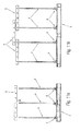
- FIG. 23 shows a side view of a plurality of different configurations of transport racks and/or storage racks in accordance with the invention with support elements provided at different heights and with different positions and arranged on base plates of different sizes.
- top, bottom, left, right, front, rear, etc. exclusively relate to the respective illustration and position of the transport rack and/or storage rack, the support elements, crossbar, standing strip and the like, which illustration and position are selected as examples in the illustrations. These terms are not to be understood as restrictive, i.e., these references may change in different operating positions or due to mirror-symmetric design or the like.
- FIG. 1 shows altogether a first embodiment of a transport rack and/or storage rack in accordance with the invention with the reference numeral 1 .
- the transport rack and/or storage rack 1 for the standing or upright transport and/or for standing storage of plate-shaped goods 2 , such as windows, doors, metal plates or wood panels, comprises at least two support elements 4 , between which at least one crossbar 5 is arranged that connects the two support elements 4 to each other.
- a standing strip 6 which is oriented perpendicularly to the crossbar, is arranged at a first end 41 of each of the support elements 4 , which standing strip 6 can be detachably fixed to a base plate 3 by resting thereon, said base plate 3 preferably being provided in form of a pallet, especially a single-use pallet.
- base plates can also be considered, e.g. transport pallets capable for multiple use such as Euro pallets.
- the support elements 4 are formed as integral or multipart plates, wherein the leaning edges 44 , 45 , which are provided for leaning the plate-shaped goods 2 on the support elements 4 , approach each other at an acute angle away from a base side 42 of the support elements 4 , said base side being arranged on the standing strip 6 .
- the support elements 4 can be formed as plates made from one-piece or as plate parts composed of two or more thereof which are glued together or mechanically connected to each other for example.
- the support elements 4 as shown in the drawings are preferably formed in a trapezoidal manner, wherein the base side 42 arranged on the standing strip 6 and an upper edge 43 opposite thereof form the base sides of the trapeze.
- the upper edge 43 can be formed so that it does not extend in parallel to the base side 42 but at an angle thereto, and to thus cut it into said shape.
- the crossbar 5 can preferably be mounted on said upper edge 43 of the support elements 4 .
- the crossbar 5 comprises several slots 52 arranged on a longitudinal side 51 and in which the upper edges 43 of the support elements 4 are accommodated in the assembled state.
- two, three or four support elements 4 are fastened to a base plate 3 in parallel respect to each other, which are stabilized by one, two or also three crossbars 5 in the region of the upper edge 43 of the support elements 4 , through which the transport rack and/or storage rack 1 can generally be mounted in a highly flexible manner on the basis of the respective requirements and dimensions of the plate-shaped goods 2 to be transported or stored.
- the slots 52 in the longitudinal side 51 of each of the crossbars 5 determine the possible distances between two each of the support elements 4 .
- the fastening of the support elements 4 to a base plate 3 preferably formed as a pallet, preferably occurs by tensioning straps 8 , as shown in FIG. 2 .
- the tensioning straps 8 are preferably formed as a tensioning belt, steel belt or plastic band.
- the tensioning straps 8 are placed around the standing strips 6 and the support boards 3 for fastening the support elements 4 , so that after the tightening of the tensioning straps 8 the standing strips 6 are fastened in a friction-locked manner to the base plate 3 in the state of the transport rack and/or storage rack 1 when fixed to the base plate 3 .
- the tensioning straps 8 preferably rest on an upper side 61 of the standing strips 6 along the longitudinal extension of the standing strips 6 .
- the fixing of the standing strip 6 with the support elements 4 preferably occurs via plates 62 , 63 , which extend along the base side 42 of the support elements 4 and between which the first end 41 of the support elements 4 is accommodated.
- each of the support elements 4 is connected via a bending or pivoting element 7 to the standing strip 6 .
- Said bending or pivoting element 7 can be formed as a hinge for example, with which the support element 4 can be pivoted from a plane parallel to the support surface of the standing strip 6 (shown in FIG. 8 b ) to a position placed perpendicularly to the support surface of the standing strip 6 (shown in FIG. 8 d ;
- FIG. 8 c illustrates the pivoting process of the support elements 4 in the pivoting direction S).
- the bending or pivoting element 7 is formed as a flexible sheet metal, especially a flexible nail plate, with which the support element 4 can be pivoted from a plane parallel to the support surface of the standing strip 6 to a position placed perpendicularly to the support surface of the standing strip 6 by bending the sheet metal, and is fixed by means of the nails of the nail plate to the support element and the standing strip.
- the crossbars 5 are mounted on the upper edge 43 of the support elements 4 for stabilizing the support elements 4 .
- each of the support elements 4 comprises at least one recess 46 through which the fastening straps 9 can be guided for fixing the plate-shaped goods 2 .
- a transport rack and/or storage rack 1 loaded with plate-shaped goods 2 is shown in FIG. 7 .
- the plate-shaped goods 2 stand on both sides of the support elements 4 , leaning on the leaning edges 44 , 45 on the base plate 3 , which in this case is a Euro pallet.
- the corners and/or at least parts of the side edges of the plate-shaped goods are protected by mountable protection elements 10 , 11 .
- a stack of plate-shaped goods 2 leaning on one side of the support elements 4 is surrounded by a fastening strap 9 .
- stops 64 are preferably arranged at the ends of the support surfaces of the standing strips 6 which are spaced from each other in the longitudinal extension.
- the support elements 4 By forming the support elements 4 as integral or multipart plates made from a material that is easy to process, they can also be produced in a simple way in different heights, as shown in FIGS. 5 a to 5 c.
- the transport rack and/or storage rack 1 can also be formed in such a way that the support elements 4 are arranged on the base plate at the edge side, wherein the support elements 4 are formed with only one leaning edge which projects back upwardly at an acute angle in relation to the longitudinal extension of the support elements 4 , so that the plate-shaped goods 2 are only leaned onto one side of the support elements 4 .
- the second leaning edge 45 which is not used in this case as a leaning edge is oriented perpendicularly to the base side 42 , arranged on the standing strip 6 , which leaning edge 45 is preferably vertical when used.
- FIGS. 12 to 20 show further embodiments of the transport rack and/or storage rack in accordance with the invention.
- FIG. 12 shows a transport rack and/or storage rack 1 with two support elements 4 arranged at a distance from each other
- FIG. 13 shows a transport rack and/or storage rack 1 with four support elements 4 arranged at a distance from each other.
- FIG. 23 shows a side view of several variants of transport racks and/or storage racks 1 with different sized support elements 4 and with support elements 4 arranged at different positions on base plates of different sizes.
- the first end 41 of the support elements 4 is provided with a projection 411 which is formed in the manner of a trapeze and which, extending away from a base side 412 of the respective support element 4 resting on the standing strip 6 , is accommodated in a recess of the standing strip 6 provided with respectively formed oblique supporting surfaces.
- the trapezoidal projection 411 which is shown in FIG. 16 in detail and whose base side 412 is broader in the longitudinal extension of the standing strip 6 than the region of the projection 411 directly before the transition into the main body of the support element 4 , comprises oblique side surfaces 413 , which converge via a rounded portion 414 into the base side 412 of the support element 4 resting on the standing strip 6 .
- the rounded portion 414 prevents a breakout of a thin-walled end region of the oblique edge of the standing strip 6 .
- This trapezoidal mortise allows further improved retaining of the support element 4 on the standing strip 6 .
- the standing strip 6 comprises respective guide recesses 65 in the region of its front edges, in which the tensioning strap rests in a manner secured against lateral slippage.
- the tensioning strap 8 engages around the standing strip 6 in the longitudinal direction of the standing strip 6 and rests on an upper side 61 of the standing strip 6 , on which the base side 412 of the support element 4 also rests.
- an additional fixing element 63 which is formed as square timber for example, is directly fastened to the standing strip along the base side 42 of the support elements 4 , which fixing element is used for additional stabilization of the support element 4 .
- each of the support elements 4 comprises a recess 47 with two grooves 472 extending away from the central opening 473 , this being in addition to the aforementioned recess 46 , through which the fastening straps 9 can be guided for fixing the plate-shaped goods 2 , or also alternatively to said recess, e.g. in the case of support elements 4 as shown in FIG. 23 in the uppermost row which have an only very low overall height.
- the inner boundary of said grooves 472 is limited by a tongue 471 extending in the longitudinal direction of the support element 4 from an edge of the recess 47 to the opening 473 .
- the tongue 471 is used as an abutment for a loop of a fastening strap 12 , with which the plate-shaped good 2 can be fixed to the support element 4 and the base plate 3 .
- the loop of the fastening strap 12 can be guided through the grooves 472 , thereby engaging behind the tongue 471 . This enables a tensioning of plate-shaped goods 2 in the manner as shown in FIG. 15 for example.
- a tensioning strap 12 is thus respectively provided in a front support element 4 and a rear support element 4 , which tensioning strap, coming from a side edge of the plate-shaped good 2 , is guided through the grooves 472 and thereby engages behind the tongue 471 , as shown in FIGS. 17 and 18 .
- the tensioning strap 12 extends from the recess 47 in a downwardly oblique manner to the base plate 3 and is guided through the respective window openings in the base plate 3 preferably formed as a pallet and thus tensions the base plate 3 with the support element 4 and the plate-shaped good 2 against slippage of the plate-shaped good 2 transversely to the longitudinal extension of the support elements 4 .
- the plate-shaped good 2 is thus secured against slippage relative to the transport rack and/or storage rack 1 by attaching such fastening straps 12 on a front and a rear support element 4 .
- a recess 47 formed in this manner provides slippage protection of plate-shaped goods 2 , which are either arranged on one side of the support elements 4 or also in a clamping fashion between the support elements 4 , as shown in FIG. 15 .
- a further fastening strap 9 is preferably guided through the opening 473 of the recess 47 .
- the fastening strap 9 extends over the entire width of the plate-shaped good 2 and is guided through the openings 473 of the support elements 4 arranged one behind the other, as a result of which the plate-shaped good 2 is rigidly fixed to the respective leaning edge 44 , 45 of the support elements 4 .
- a respective lug 474 extends into the opening 473 from at least one side edge 475 of the opening 473 , preferably from both side edges 475 of the opening 473 , with which slippage of the respective fastening strap 9 is effectively prevented in the tensioned state in the direction of the grooves 472 .
- the tongue 471 is formed in such a way that it tapers slightly up to the upper root, i.e. the width B Z1 of the tongue 471 close to the free end of the tongue 471 is greater than the width B Z2 of the tongue 471 close to the root of the tongue.
- the tapering angle ⁇ shown in FIG. 17 is preferably selected relatively low, especially less than 20°.
- FIG. 19 shows a further embodiment of a support element 4 , in which the recess 47 , through which the fastening straps 12 can be guided for fixing the plate-shaped goods 2 , are formed as separate elongated slots.
- the orientation of the elongated slots 48 is preferably parallel to that of the edges 44 , 45 . It can also be considered to orient the recesses 48 formed as elongated slots in parallel with respect to each other.
- the crossbar 5 comprises a further slot 53 formed as an expansion slot adjacent to each of the slots 52 , this being in addition to the slots 52 for accommodating the respective edges of the support elements 4 .
- the slots 52 , 53 are respectively arranged in pairs adjacent to each other.
- the width b 1 of the first slot 52 of a pair of slots provided for accommodating the edges of the support elements 4 is greater than the width b 2 of the second slot 53 .
- the production tolerances in the thickness of the support elements 4 can be compensated by these additional expansion slots 53 , whilst maintaining constant widths b 1 of the first slots 52 .
- first slots 52 which are used for accommodating an edge 43 or a leaning edge 44 , 45 of the support elements 4 , in a very precise custom-fit manner relative to the intended thickness of the support elements 4 , so that when a crossbar 5 is mounted in the region of the leaning edges 44 , 45 of the support elements 4 , as shown in FIG. 21 , the crossbar 5 is tightly clamped in such a way that as a result of friction it does not slip from the support elements 4 .
- the aforementioned support elements 4 with the recesses 47 are principally also suitable for a transport rack and/or storage rack 1 without a crossbar 5 .
- support elements 4 with a projection formed in the manner of a trapeze which are also suitable for a transport rack and/or storage rack 1 in which the support elements 4 are not supported via crossbars 5 , but were the transverse support occurs via the attached plate-shaped goods 2 themselves.
Landscapes
- Engineering & Computer Science (AREA)
- Mechanical Engineering (AREA)
- Packaging Of Annular Or Rod-Shaped Articles, Wearing Apparel, Cassettes, Or The Like (AREA)
- Pallets (AREA)
Abstract
A transport rack and/or storage rack for standing transport and/or standing storage of plate-shaped goods, such as windows or doors, includes at least two support elements. A standing strip is arranged on a first end of each of the support elements and is removably fastenable, resting on a floor plate. The support elements are connected to each other by at least one crossbar placed on the support elements and the standing strip is aligned perpendicularly to the crossbar. The support elements are single or multi-part plates, having two leaning edges approaching each other at an acute angle away from a base side arranged on the standing strip.
Description
Exemplary embodiments of the invention are directed to a transport rack and/or storage rack, and arrangement of a transport rack and/or storage rack on a base plate.
The present invention relates to a transport rack and/or storage rack for standing transport or standing storage of plate-shaped goods, especially windows, doors, glass panes or stone slabs, as well as an arrangement of a transport rack and/or storage rack on a base plate.
Generic transport racks and/or storage racks are known for example from German patent documents DE 10 2011 053 460 A1 and DE 100 10 325 A1.
The transport rack and/or storage rack disclosed in DE 10 2011 053 460 A1 substantially consists of two a-shaped frame parts with upright bars arranged at an acute angle with respect to each other, on which the plate-shaped elements such as glass panels can be leaned. Base strips are fixed to the upright bars formed as square tube profiles, on which fastening means are welded which engage around a transverse board of a Euro pallet.
DE 100 10 325 A1 discloses a transport frame, in which the frame parts are made of profiled steel and is formed as a folding apparatus, connected to each other by joints.
Both frames have a common disadvantage in that they require a large amount of storage place. In particular, these transport frames are further relatively expensive to purchase as a result of their material and their joints etc.
The frames according to DE 10 2011 053 460 A1 can only be fixed to specific pallets, especially Euro pallets, as a result of the fastening means welded onto the base strips, because they are placed in gaps between the cover boards of the pallet. Furthermore, the pallet must comprise transverse boards oriented perpendicularly to the cover boards and surrounded by the fastening means for fixing the frames.
The return transport of such transport frames is also relatively expensive as a result of their relatively high need for space and their large mass.
Exemplary embodiments of the present invention are directed to a transport rack and/or storage rack for the standing transport and/or standing storage of plate-shaped goods, as well as an arrangement of a transport rack and/or storage rack on a base plate, which can be produced at low cost and can be transported (back) at low cost.
According to one aspect of the invention, the transport rack and/or storage rack comprises at least two support elements. A standing strip is arranged on a first end of each of the support elements, which standing strip is removably fastenable to a base plate, in particular a pallet, while resting thereon.
The support elements are formed as single or multipart plates, having two leaning edges approaching each other at an acute angle away from a base side arranged on the standing strip. Furthermore, the support elements are connected to each other by at least one crossbar that is attachable to the support elements.
Such a transport rack and/or storage rack can be produced and designed in an exceptionally cost-effective manner because it can be assembled and disassembled with the simplest means.
The capability for simplified disassembly offers the further major advantage that a return transport of such a transport rack and/or storage rack after use can occur in an exceptionally compact way by taking the transport rack and/or storage rack apart.
The ability to attach the crossbar contributes to the simple mounting and dismounting of the transport rack and/or storage rack and also ensures an adequately stable connection between the support elements.
As a result of the cost-effective production, the transport rack and/or storage rack in accordance with the invention can generally be used as a so-called single-use frame, so that a return transport of the transport rack and/or storage rack is merely optional.
It can also be considered, as a result of the cost-effective production of the transport rack and/or storage rack in accordance with the invention, to use a so-called single-use pallet and to entirely forgo a return transport of the transport rack and/or storage rack.
This ensures that it is not necessary to exchange transport racks and/or storage racks or the base plates in the case of a delivery of plate-shaped goods with a transport rack and/or storage rack in accordance with the invention.
Especially in the case of customers that do not have any Euro pallets on stock for the exchange of goods, the use of the transport rack and/or storage rack in accordance with the invention, in conjunction with a single-use pallet, allows a simple and uncomplicated delivery of plate-shaped goods without having to exchange transport racks and/or storage racks and/or pallets, or having to deposit collateral for the transport racks and/or storage racks and/or pallets.
According to an aspect of the invention, the first end of the support elements comprises a protrusion formed in the manner of a trapeze and accommodated in a respectively shaped recess of the standing strip, extending away from a base side of the respective support element, said base side resting on the standing strip.
This leads to an exceptionally stable connection between the spanning strip and the support element.
According to an aspect of the invention, the transport rack and/or storage rack comprises at least two support elements. A standing strip is arranged at a first end of each of the support elements, which standing strip is removably fastenable to a base plate, especially a pallet.
Each of the support elements comprises at least one recess, through which a fastening strap can be guided for fixing the plate-shaped goods, wherein the recess comprises two grooves extending away from an opening, whose inner boundary is delimited by a tongue extending in the longitudinal direction of the support element from an edge of the recess to the opening, wherein a loop of the fastening strap, with which the plate-shaped article can be fixed to the support element and the base plate, can be guided through the grooves while engaging behind the tongue.
A recess formed in this manner allows an exceptionally stable fixing of the plate-shaped item to be transported on the support element and the base plate. By fixing the item with a fastening strap, the connection between the standing strip, the support element and the base plate is additionally reinforced.
According to one aspect of the invention, at least one crossbar comprises several slots arranged on a longitudinal edge, which allows a variable distance of the support element from each other.
In a preferred embodiment, the slots are arranged in pairs adjacent to each other, wherein the width of a first slot of a pair of slots is greater than the width of a second slot of a pair of slots, wherein the first slot is formed as a receiving slot for accommodating an upper edge or a leaning edge of the support element and the second slot as an expansion slot.
This promotes the mounting of the crossbar on the support element. Furthermore, the expansion slots allow a compensation of production tolerances concerning the material thickness of the support elements.
For the purpose of retaining the support elements on the standing strip, the first end of each support element is preferably retained in an interlocking manner on the standing strip at least along the base side of the support element.
According to a further preferred embodiment of the invention, the leaning edges of the support elements are equally long and are preferably formed under the same acute angle in relation to the longitudinal axis of the support elements. With such a transport rack and/or storage rack, the plate-shaped goods can be transported and/or stored in a leaning manner on both sides on the support elements.
According to an alternative embodiment, the first leaning edge of each support element is oriented perpendicularly to the base side of the plate, wherein the plate-shaped goods can be leaned on a second leaning edge. The second leaning edge extends at an acute angle from a base side arranged on the standing strip towards the first leaning edge. With such a transport rack and/or storage rack, the plate-shaped goods can be transported and/or stored in a leaning manner on one side on one of the leaning edges of the support elements.
According to a further embodiment of the invention, the support elements are formed as trapezoidal plates, having an upper edge parallel to the base side, on which the at least one crossbar is mounted.
The support elements, the at least one crossbar and the standing strip are made in an especially preferred way from wood, metal or a dimensionally stable base material, which ensures a simple and cost-effective production of the transport rack and/or storage rack.
According to a further preferred embodiment of the invention, each of the support elements comprises at least one recess, through which fastening straps can be guided for fixing the plate-shaped goods. The recess is preferably formed in a round manner, but polygonal (e.g. trapezoidal) recesses can also be considered.
According to a further preferred embodiment of the invention, stops are arranged at the ends of the support surface, which stops are spaced from each other in the longitudinal direction and which prevent slippage of the plate-shaped goods from the leaning edges.
According to a further embodiment of the invention, the width of the tongue close to the free end of the tongue is greater than the width of the tongue close to the root of the tongue. This prevents slippage of the fastening strap enclosing the tongue, especially during transport, in which numerous jolts and vibrations of the transport rack and/or storage rack occur as a result of bumpy roads.
The arrangement of a transport rack and/or storage rack in accordance with the invention on a base plate, especially a pallet, especially a single-use pallet, is characterized in that the standing strip, in a state where the transport rack and/or storage rack is fixed to a base plate, is fixed in a friction-locked manner to the base plate by means of a tensioning strap.
Such a tensioning strap provides a simple and cost-effective fixing of the support elements fixed to the standing strip.
The tensioning strap is preferably formed as a tensioning belt, steel belt or plastic band.
Embodiments of the invention are explained below in closer detail by reference to the enclosed drawings wherein:
In the following description of the drawings, terms such as top, bottom, left, right, front, rear, etc. exclusively relate to the respective illustration and position of the transport rack and/or storage rack, the support elements, crossbar, standing strip and the like, which illustration and position are selected as examples in the illustrations. These terms are not to be understood as restrictive, i.e., these references may change in different operating positions or due to mirror-symmetric design or the like.
The transport rack and/or storage rack 1 for the standing or upright transport and/or for standing storage of plate-shaped goods 2, such as windows, doors, metal plates or wood panels, comprises at least two support elements 4, between which at least one crossbar 5 is arranged that connects the two support elements 4 to each other.
A standing strip 6, which is oriented perpendicularly to the crossbar, is arranged at a first end 41 of each of the support elements 4, which standing strip 6 can be detachably fixed to a base plate 3 by resting thereon, said base plate 3 preferably being provided in form of a pallet, especially a single-use pallet.
The use of other configurations of base plates can also be considered, e.g. transport pallets capable for multiple use such as Euro pallets.
The support elements 4 are formed as integral or multipart plates, wherein the leaning edges 44, 45, which are provided for leaning the plate-shaped goods 2 on the support elements 4, approach each other at an acute angle away from a base side 42 of the support elements 4, said base side being arranged on the standing strip 6.
The support elements 4 can be formed as plates made from one-piece or as plate parts composed of two or more thereof which are glued together or mechanically connected to each other for example.
The support elements 4 as shown in the drawings are preferably formed in a trapezoidal manner, wherein the base side 42 arranged on the standing strip 6 and an upper edge 43 opposite thereof form the base sides of the trapeze. The upper edge 43 can be formed so that it does not extend in parallel to the base side 42 but at an angle thereto, and to thus cut it into said shape.
The crossbar 5 can preferably be mounted on said upper edge 43 of the support elements 4.
As is shown in FIGS. 1 to 4 , the crossbar 5 comprises several slots 52 arranged on a longitudinal side 51 and in which the upper edges 43 of the support elements 4 are accommodated in the assembled state.
Depending on the dimensions of the plate-shaped goods 2 which are to be stored or transported, as shown for example in FIGS. 1 to 4 and 11 a to 11 d, two, three or four support elements 4 are fastened to a base plate 3 in parallel respect to each other, which are stabilized by one, two or also three crossbars 5 in the region of the upper edge 43 of the support elements 4, through which the transport rack and/or storage rack 1 can generally be mounted in a highly flexible manner on the basis of the respective requirements and dimensions of the plate-shaped goods 2 to be transported or stored.
The slots 52 in the longitudinal side 51 of each of the crossbars 5 determine the possible distances between two each of the support elements 4.
The fastening of the support elements 4 to a base plate 3, which is preferably formed as a pallet, preferably occurs by tensioning straps 8, as shown in FIG. 2 .
The tensioning straps 8 are preferably formed as a tensioning belt, steel belt or plastic band. The tensioning straps 8 are placed around the standing strips 6 and the support boards 3 for fastening the support elements 4, so that after the tightening of the tensioning straps 8 the standing strips 6 are fastened in a friction-locked manner to the base plate 3 in the state of the transport rack and/or storage rack 1 when fixed to the base plate 3.
As is shown in FIG. 2 , the tensioning straps 8 preferably rest on an upper side 61 of the standing strips 6 along the longitudinal extension of the standing strips 6.
The fixing of the standing strip 6 with the support elements 4 preferably occurs via plates 62, 63, which extend along the base side 42 of the support elements 4 and between which the first end 41 of the support elements 4 is accommodated.
In an especially preferred embodiment, which is shown in FIGS. 8a to 8d , the first end 41 of each of the support elements 4 is connected via a bending or pivoting element 7 to the standing strip 6.
Said bending or pivoting element 7 can be formed as a hinge for example, with which the support element 4 can be pivoted from a plane parallel to the support surface of the standing strip 6 (shown in FIG. 8b ) to a position placed perpendicularly to the support surface of the standing strip 6 (shown in FIG. 8d ; FIG. 8c illustrates the pivoting process of the support elements 4 in the pivoting direction S).
In an alternative embodiment, the bending or pivoting element 7 is formed as a flexible sheet metal, especially a flexible nail plate, with which the support element 4 can be pivoted from a plane parallel to the support surface of the standing strip 6 to a position placed perpendicularly to the support surface of the standing strip 6 by bending the sheet metal, and is fixed by means of the nails of the nail plate to the support element and the standing strip.
After the erection of the support elements 4 to the position placed perpendicularly to the support surface of the standing strip 6, the crossbars 5 are mounted on the upper edge 43 of the support elements 4 for stabilizing the support elements 4.
In order to also allow the fixing of the plate-shaped goods that are placed on the transport rack and/or storage rack 1 after its assembly in a simple manner, each of the support elements 4 comprises at least one recess 46 through which the fastening straps 9 can be guided for fixing the plate-shaped goods 2. A transport rack and/or storage rack 1 loaded with plate-shaped goods 2 is shown in FIG. 7 .
The plate-shaped goods 2 stand on both sides of the support elements 4, leaning on the leaning edges 44, 45 on the base plate 3, which in this case is a Euro pallet. The corners and/or at least parts of the side edges of the plate-shaped goods are protected by mountable protection elements 10, 11. A stack of plate-shaped goods 2 leaning on one side of the support elements 4 is surrounded by a fastening strap 9.
In order to prevent the plate-shaped goods 2 from slipping away from an outer edge of the support surface of the standing strips 6, stops 64 are preferably arranged at the ends of the support surfaces of the standing strips 6 which are spaced from each other in the longitudinal extension.
The supporting elements 4, the at least one crossbar 5 and the standing strips 6 are preferably made from wood, metal or dimensionally stable plastic.
By forming the support elements 4 as integral or multipart plates made from a material that is easy to process, they can also be produced in a simple way in different heights, as shown in FIGS. 5a to 5 c.
The transport rack and/or storage rack 1 can also be formed in such a way that the support elements 4 are arranged on the base plate at the edge side, wherein the support elements 4 are formed with only one leaning edge which projects back upwardly at an acute angle in relation to the longitudinal extension of the support elements 4, so that the plate-shaped goods 2 are only leaned onto one side of the support elements 4.
As illustrated in FIGS. 6a to 6c , the second leaning edge 45 which is not used in this case as a leaning edge is oriented perpendicularly to the base side 42, arranged on the standing strip 6, which leaning edge 45 is preferably vertical when used.
In the embodiment shown in FIGS. 12 to 15 and in contrast to the embodiment shown in FIG. 1 , the first end 41 of the support elements 4 is provided with a projection 411 which is formed in the manner of a trapeze and which, extending away from a base side 412 of the respective support element 4 resting on the standing strip 6, is accommodated in a recess of the standing strip 6 provided with respectively formed oblique supporting surfaces.
The trapezoidal projection 411, which is shown in FIG. 16 in detail and whose base side 412 is broader in the longitudinal extension of the standing strip 6 than the region of the projection 411 directly before the transition into the main body of the support element 4, comprises oblique side surfaces 413, which converge via a rounded portion 414 into the base side 412 of the support element 4 resting on the standing strip 6.
The rounded portion 414 prevents a breakout of a thin-walled end region of the oblique edge of the standing strip 6. This trapezoidal mortise allows further improved retaining of the support element 4 on the standing strip 6.
For the purpose of accommodating a tensioning strap 8, the standing strip 6 comprises respective guide recesses 65 in the region of its front edges, in which the tensioning strap rests in a manner secured against lateral slippage. The tensioning strap 8 engages around the standing strip 6 in the longitudinal direction of the standing strip 6 and rests on an upper side 61 of the standing strip 6, on which the base side 412 of the support element 4 also rests.
In the embodiment shown in FIG. 14 , an additional fixing element 63, which is formed as square timber for example, is directly fastened to the standing strip along the base side 42 of the support elements 4, which fixing element is used for additional stabilization of the support element 4.
As is further shown in FIGS. 12 to 15 and in a detailed view in FIG. 17 , each of the support elements 4 comprises a recess 47 with two grooves 472 extending away from the central opening 473, this being in addition to the aforementioned recess 46, through which the fastening straps 9 can be guided for fixing the plate-shaped goods 2, or also alternatively to said recess, e.g. in the case of support elements 4 as shown in FIG. 23 in the uppermost row which have an only very low overall height.
The inner boundary of said grooves 472 is limited by a tongue 471 extending in the longitudinal direction of the support element 4 from an edge of the recess 47 to the opening 473.
The tongue 471 is used as an abutment for a loop of a fastening strap 12, with which the plate-shaped good 2 can be fixed to the support element 4 and the base plate 3.
The loop of the fastening strap 12 can be guided through the grooves 472, thereby engaging behind the tongue 471. This enables a tensioning of plate-shaped goods 2 in the manner as shown in FIG. 15 for example.
A tensioning strap 12 is thus respectively provided in a front support element 4 and a rear support element 4, which tensioning strap, coming from a side edge of the plate-shaped good 2, is guided through the grooves 472 and thereby engages behind the tongue 471, as shown in FIGS. 17 and 18 . The tensioning strap 12 extends from the recess 47 in a downwardly oblique manner to the base plate 3 and is guided through the respective window openings in the base plate 3 preferably formed as a pallet and thus tensions the base plate 3 with the support element 4 and the plate-shaped good 2 against slippage of the plate-shaped good 2 transversely to the longitudinal extension of the support elements 4.
The plate-shaped good 2 is thus secured against slippage relative to the transport rack and/or storage rack 1 by attaching such fastening straps 12 on a front and a rear support element 4.
A recess 47 formed in this manner provides slippage protection of plate-shaped goods 2, which are either arranged on one side of the support elements 4 or also in a clamping fashion between the support elements 4, as shown in FIG. 15 .
As shown in FIGS. 15 to 17 , a further fastening strap 9 is preferably guided through the opening 473 of the recess 47. The fastening strap 9 extends over the entire width of the plate-shaped good 2 and is guided through the openings 473 of the support elements 4 arranged one behind the other, as a result of which the plate-shaped good 2 is rigidly fixed to the respective leaning edge 44, 45 of the support elements 4.
In order to prevent slippage of the fastening strap 9 guided through the opening 473, a respective lug 474 extends into the opening 473 from at least one side edge 475 of the opening 473, preferably from both side edges 475 of the opening 473, with which slippage of the respective fastening strap 9 is effectively prevented in the tensioned state in the direction of the grooves 472.
In order to prevent slippage of the fastening strap 12 in the upward direction which is guided through the grooves 472, as shown in the configuration as illustrated in FIGS. 15 to 17 , the tongue 471 is formed in such a way that it tapers slightly up to the upper root, i.e. the width BZ1 of the tongue 471 close to the free end of the tongue 471 is greater than the width BZ2 of the tongue 471 close to the root of the tongue. The tapering angle α shown in FIG. 17 , about which the side walls 476 of the tongue 471 are inclined relative to the vertical, is preferably selected relatively low, especially less than 20°.
As is shown in FIGS. 13 to 15 and 20 a to f, the crossbar 5 comprises a further slot 53 formed as an expansion slot adjacent to each of the slots 52, this being in addition to the slots 52 for accommodating the respective edges of the support elements 4.
The slots 52, 53 are respectively arranged in pairs adjacent to each other. The width b1 of the first slot 52 of a pair of slots provided for accommodating the edges of the support elements 4 is greater than the width b2 of the second slot 53.
The production tolerances in the thickness of the support elements 4 can be compensated by these additional expansion slots 53, whilst maintaining constant widths b1 of the first slots 52.
It is thus additionally possible to form the first slots 52, which are used for accommodating an edge 43 or a leaning edge 44, 45 of the support elements 4, in a very precise custom-fit manner relative to the intended thickness of the support elements 4, so that when a crossbar 5 is mounted in the region of the leaning edges 44, 45 of the support elements 4, as shown in FIG. 21 , the crossbar 5 is tightly clamped in such a way that as a result of friction it does not slip from the support elements 4.
As is shown in FIG. 22 , the aforementioned support elements 4 with the recesses 47 are principally also suitable for a transport rack and/or storage rack 1 without a crossbar 5.
The same also applies to support elements 4 with a projection formed in the manner of a trapeze, which are also suitable for a transport rack and/or storage rack 1 in which the support elements 4 are not supported via crossbars 5, but were the transverse support occurs via the attached plate-shaped goods 2 themselves.
Although the present invention has been described above by means of embodiments with reference to the enclosed drawings, it is understood that various changes and developments can be implemented without leaving the scope of the present invention, as it is defined in the enclosed claims.
- 1 Transport rack and/or storage rack
- 2 Plate-shaped goods
- 3 Base plate
- 4 Support elements
- 5 Crossbar
- 6 Standing strip
- 7 Pivoting element
- 8 Tensioning strap
- 9 Fastening strap
- 10 Protection element
- 11 Protection element
- 12 Tensioning strap
- 41 First end
- 42 Base side
- 43 Upper edge
- 44 Leaning edge
- 45 Leaning edge
- 46 Recess
- 47 Strap leadthrough
- 48 Strap leadthrough
- 51 Longitudinal side
- 52 Slots
- 53 Expansion slot
- 61 Upper side
- 62 Plate
- 63 Plate
- 64 Stop
- 65 Guide recess
- 411 Trapeze
- 412 Base side
- 413 Oblique edge
- 414 Recess
- 415 Base side
- 471 Tongue
- 472 Slot
- 473 Opening
- 474 Lug
- 475 Inner side wall
- 476 Side wall of tongue
- α Tapering angle
- b1 Slot width
- b2 Slot width
- bZ1 Width of the free end of the tongue
- bZ2 Width of the tongue in the root region of the tongue
Claims (10)
1. A transport storage rack for transporting and storing plate-shaped goods, including windows, doors, glass panes or stone slabs, the transport storage rack comprising:
a base plate;
at least two support elements each having a top end and an opposite bottom end, wherein the at least two support elements are each a trapezoidal panel with two angled edges;
a standing strip arranged at the bottom end of each of the at least two support elements, wherein each of the standing strips rest upon and is removably fastenable to the base plate;
at least one crossbar mounted directly on a top surface of the top end of each support element or a corresponding angled edge from said two angled edges of each support element to extend across and connect the at least two support elements to each other,
wherein each of the standing strips is oriented perpendicularly to the at least one crossbar,
wherein the at least one crossbar comprises several slots arranged on a bottom edge of the at least one crossbar, wherein the slots are configured to receive said top surfaces or the corresponding angled edges of the at least two support elements; and
wherein the bottom end of each support element has a first width and the top end of each support element has a second width, wherein the first width is greater than the second width, and the angled edges of each support element taper towards each other from the bottom end of each support element to the top end of each support element;
wherein the bottom end of each support elements comprises a trapezoidal projection, the trapezoidal projection comprising a top end and an opposite bottom end, and two angled edges, wherein the bottom end of each trapezoidal projection has a third width and the top end of each trapezoidal projection has a fourth width, wherein the third width is greater than the fourth width, and the angled edges of each trapezoidal projection taper towards each other from the bottom end of each trapezoidal projection to the top end of each trapezoidal projection;
wherein each trapezoidal projection is received in a respectively trapezoidal shaped recess of one of the standing strips, to support each support element in an upright manner on the base plate.
2. The transport rack storage rack of claim 1 , wherein the slots of the least one cross bar are respectively arranged in pairs adjacent to each other, wherein a width of a first slot of a pair of slots from said several slots is greater than a width of a second slot of said pair of slots from said several slots, wherein the first slot is a receiving slot for accommodating a corresponding top surface from said top surfaces of said at least two support elements, and the second slot is an expansion slot.
3. The transport rack storage rack of claim 1 , wherein each trapezoidal projection is retained on said one of the standing strips in an interlocking manner.
4. The transport rack storage rack of claim 1 , wherein the two angled edges of each support element are symmetric about a central axis of each support element.
5. The transport rack storage rack of claim 1 , wherein the support elements are trapezoidal plates having an upper edge parallel to the base side of the respective support element.
6. The transport rack storage rack of claim 1 , wherein each of the at least two support elements comprises at least one recess through which fastening straps can be guided for fixing the plate-shaped goods to the at least two support elements.
7. The transport rack storage rack of claim 6 , wherein one of the at least one recess of the at least two support elements comprises
an upper opening and a lower opening with a pair of lugs formed therebetween, wherein a tongue is formed in the lower opening and extends upwardly from a bottom surface of the lower opening, wherein two grooves are defined between the tongue and side walls of the lower opening, wherein a loop of the fastening strap, with which the plate-shaped goods is fixable to the at least two support element and the base plate, can be guided through the grooves and behind the tongue.
8. A transport storage rack for transporting and storing plate-shaped goods, including windows, doors, glass panes or stone slabs, the transport storage rack comprising:
a base plate;
at least two support elements each having a top end and an opposite bottom end, wherein the at least two support elements are each a trapezoidal panel with two angled edges;
a standing strip arranged at the bottom end of each of the at least two support elements, wherein each of the standing strips rest upon and is removably fastenable to the base plate;
at least one crossbar mounted directly on a top surface of the top end of each support element or a corresponding angled edge from said two angled edges of each support element to extend across and connect the at least two support elements to each other,
wherein each of the standing strips is oriented perpendicularly to the at least one crossbar,
wherein the at least one crossbar comprises several slots arranged on a bottom edge of the at least one crossbar, wherein the slots are configured to receive said top surfaces or the corresponding angled edges of the at least two support elements; and
wherein the bottom end of each support element has a first width and the top end of each support element has a second width, wherein the first width is greater than the second width, and the angled edges of each support element taper towards each other from the bottom end of each support element to the top end of each support element;
wherein each of the support elements comprises at least one recess, through which a fastening strap can be guided for fixing the plate-shaped goods to the at least two support elements,
wherein each recess comprises an upper opening and a lower opening with a pair of lugs formed therebetween, wherein a tongue is formed in the lower opening and extends upwardly from a bottom surface of the lower opening, wherein two grooves are defined between the tongue and side walls of the lower opening, wherein a loop of the fastening strap, with which the plate-shaped goods is fixable to the at least two support elements and the base plate, can be guided through the grooves and behind the tongue.
9. The transport rack storage rack of claim 8 , wherein a first width of each tongue close to a free end of each tongue is greater than a second width of each tongue close to a proximal end of each tongue.
10. The transport rack storage rack of claim 8 , wherein each of the standing strips is secured to the base plate with a tensioning strap.
Applications Claiming Priority (4)
| Application Number | Priority Date | Filing Date | Title |
|---|---|---|---|
| DE202014103799.3U DE202014103799U1 (en) | 2014-08-15 | 2014-08-15 | Transport and / or storage rack and arrangement of a transport and / or storage rack on a base plate |
| DE202014103799U | 2014-08-15 | ||
| DE202014103799.3 | 2014-08-15 | ||
| PCT/EP2015/059935 WO2016023649A1 (en) | 2014-08-15 | 2015-05-06 | Transport rack and/or storage rack, and arrangement of a transport rack and/or storage rack on a floor plate |
Publications (2)
| Publication Number | Publication Date |
|---|---|
| US20170275051A1 US20170275051A1 (en) | 2017-09-28 |
| US10106294B2 true US10106294B2 (en) | 2018-10-23 |
Family
ID=53175480
Family Applications (1)
| Application Number | Title | Priority Date | Filing Date |
|---|---|---|---|
| US15/503,873 Active US10106294B2 (en) | 2014-08-15 | 2015-05-06 | Transport rack and/or storage rack, and arrangement of a transport rack and/or storage rack on a floor plate |
Country Status (6)
| Country | Link |
|---|---|
| US (1) | US10106294B2 (en) |
| EP (1) | EP3180270B1 (en) |
| CN (1) | CN107074435B (en) |
| DE (1) | DE202014103799U1 (en) |
| PL (1) | PL3180270T3 (en) |
| WO (1) | WO2016023649A1 (en) |
Cited By (6)
| Publication number | Priority date | Publication date | Assignee | Title |
|---|---|---|---|---|
| US20190202598A1 (en) * | 2017-12-28 | 2019-07-04 | Dennis Ray Dickson | Easy lift rack |
| US11046533B2 (en) * | 2016-07-28 | 2021-06-29 | ETAK Systems, LLC | Magnetic track system for transporting batteries at telecommunication sites |
| US20210229720A1 (en) * | 2020-01-24 | 2021-07-29 | Bbj Solutions, Llc | Cart and rack assembly |
| US20210387767A1 (en) * | 2020-06-10 | 2021-12-16 | Deltarack Bvba | Support rack for storing or transporting plate-shaped objects, combination of a transport pallet and such a support rack, kit of parts for manufacturing such a support rack and use of such a support rack |
| US20220178494A1 (en) * | 2020-12-07 | 2022-06-09 | Richard M. Roche | Stand for Maintaining Panels of Sheet Material in a Vertical Orientation |
| US20230062871A1 (en) * | 2021-08-27 | 2023-03-02 | Trulite Glass & Aluminum Solutions, LLC | A-Frame Rack Systems for Transporting Glass Sheets |
Families Citing this family (12)
| Publication number | Priority date | Publication date | Assignee | Title |
|---|---|---|---|---|
| US9428095B2 (en) * | 2013-12-09 | 2016-08-30 | Jack A. Belmont | Glass fastener system |
| IT201600095498A1 (en) * | 2016-09-22 | 2018-03-22 | Lk Lab Srl | SUPPORTING ELEMENT FOR SHEET-SHAPED OBJECTS |
| IT201600095499A1 (en) * | 2016-09-22 | 2018-03-22 | Lk Lab Srl | APPARATUS FOR POSITIONING VERTICAL ITEMS IN THE FORM OF SLAB ON A SUPPORT ELEMENT AND FIX THEM ON IT |
| IT201600124148A1 (en) * | 2016-12-07 | 2018-06-07 | Lk Lab Srl | Method for fixing slab-shaped objects to a support element |
| US10336528B2 (en) * | 2016-12-30 | 2019-07-02 | Guardian Glass, LLC | Rail car rack |
| WO2019215686A1 (en) * | 2018-05-10 | 2019-11-14 | Antonio Piazza | Disassemblable rack for sheet-like products, kit for such a rack and method of assembly |
| NL2021307B1 (en) * | 2018-07-15 | 2020-01-22 | H D Duijts Holding B V | Stand system for arranging panels |
| PL3597564T3 (en) | 2018-07-15 | 2021-07-26 | H.D. Duijts Holding B.V. | Stand system for arranging panels |
| DE202018005711U1 (en) | 2018-12-05 | 2019-01-07 | Thomas Walther | Device for transporting window elements, facade elements and / or door elements as plate-shaped building elements |
| DE102021122669A1 (en) | 2021-09-01 | 2023-03-02 | Wilhelm Wiedau | Storage rack for panel goods |
| CN115504095B (en) * | 2022-09-16 | 2023-11-28 | 彩虹(合肥)液晶玻璃有限公司 | Substrate glass semi-manufactured goods can overturn rack |
| CN116040079B (en) * | 2023-03-29 | 2023-08-15 | 张家港市永茂住宅工业有限公司 | Goods shelf for transportation |
Citations (90)
| Publication number | Priority date | Publication date | Assignee | Title |
|---|---|---|---|---|
| US163329A (en) * | 1875-05-18 | Improvement | ||
| US168751A (en) * | 1875-10-11 | Improvement in clothes-driers | ||
| US223667A (en) * | 1880-01-20 | Bow-and-arrow rack | ||
| US429023A (en) * | 1890-05-27 | Clothes-drier | ||
| US862104A (en) * | 1906-05-26 | 1907-07-30 | Moritz Rauschenbusch | Toilet-case. |
| US1628936A (en) * | 1926-03-08 | 1927-05-17 | Joseph E Cardarelle | Drying rack for bathtubs |
| US2002128A (en) * | 1934-02-19 | 1935-05-21 | Ray A Reidenbaugh | Display rack |
| US2116381A (en) * | 1936-06-16 | 1938-05-03 | Republic Steel Corp | Means for handling and shipping sheet metal |
| US2235012A (en) * | 1937-06-29 | 1941-03-18 | Oliver D Colvin | Detachable automobile carrier rack |
| US2760647A (en) * | 1956-08-28 | Saul jr | ||
| US2839198A (en) * | 1954-06-07 | 1958-06-17 | Pittsburgh Plate Glass Co | Shipping and storage carrier for sheet material |
| US2965159A (en) * | 1956-09-18 | 1960-12-20 | Annette E Fridolph | Folding furniture |
| US3147860A (en) * | 1961-03-24 | 1964-09-08 | Libbey Owens Ford Glass Co | Shipping apparatus for sheets or plates |
| US3173645A (en) * | 1963-02-25 | 1965-03-16 | Preferred Growth Capital Inc | Self setting cam hook |
| DE2236934A1 (en) | 1971-07-30 | 1973-02-15 | Opperman & Sons Ltd W | RECEIVING DEVICE FOR PLATE MATERIAL |
| US3878942A (en) * | 1973-08-01 | 1975-04-22 | Libbey Owens Ford Co | Adjustable shipping rack and means for securing flat sheets |
| US3955676A (en) * | 1973-08-01 | 1976-05-11 | Libbey-Owens-Ford Company | Adjustable shipping rack and means for securing flat sheets thereto |
| US3955731A (en) * | 1971-07-29 | 1976-05-11 | Lindelef Wesley H | Convertible top carrier-living compartment storage unit for passenger vehicles |
| JPS5584285U (en) | 1978-11-30 | 1980-06-10 | ||
| US4278171A (en) * | 1979-08-01 | 1981-07-14 | Ppg Industries, Inc. | Strap retainer and compression block |
| US4304336A (en) * | 1980-02-28 | 1981-12-08 | Mays Calvin B | Interchangeable glass rack for pickup trucks |
| US4643610A (en) * | 1986-06-30 | 1987-02-17 | Chrysler Motors Corporation | Fastener mounting assembly |
| US4880116A (en) * | 1988-03-04 | 1989-11-14 | Fluoroware, Inc. | Robotic accessible wafer shipper assembly |
| US4924557A (en) * | 1986-01-10 | 1990-05-15 | Heckerman William L | Harness |
| US5085329A (en) * | 1990-12-07 | 1992-02-04 | Crowell John W | Sheeting support |
| US5133461A (en) * | 1991-02-08 | 1992-07-28 | Racor, Inc. | Freestanding portable bicycle stand |
| US5193692A (en) * | 1992-04-13 | 1993-03-16 | Charles Farley | Recyclable dunnage support assembly |
| US5209539A (en) * | 1992-01-17 | 1993-05-11 | Edge Technologies, Inc. | Portable golf club carrier and support |
| US5226764A (en) * | 1992-04-20 | 1993-07-13 | The Louis Berkman Company | Method and apparatus for securing a load to a vehicle |
| US5240123A (en) * | 1992-06-19 | 1993-08-31 | Hawk Gary D | Baseball cap holder |
| US5269422A (en) * | 1993-02-22 | 1993-12-14 | Gestion 127 Inc. | Windshield and protecting divider assembly |
| US5284256A (en) * | 1992-08-19 | 1994-02-08 | Correll Antoun Holly E K | Child's book stand |
| US5349770A (en) * | 1993-02-23 | 1994-09-27 | Roy Bursey | Frame display arrangement for displaying thin, flat objects |
| US5398832A (en) * | 1992-10-27 | 1995-03-21 | Clive-Smith; Martin | Lashings in folding flatrack |
| US5411360A (en) * | 1993-10-19 | 1995-05-02 | Libbey-Owens-Ford Co. | Apparatus for transporting sheet material |
| JPH07137742A (en) | 1993-11-19 | 1995-05-30 | Inax Corp | Panel transportation pallet |
| US5515977A (en) * | 1995-08-10 | 1996-05-14 | Union Camp Corporation | Edge protecting packaging and distribution system for rolled laminar stock |
| US5685437A (en) * | 1994-09-27 | 1997-11-11 | Lisec; Peter | Device for storing glass plates or insulating glass panes |
| DE29722858U1 (en) | 1997-12-24 | 1998-02-26 | Probst Juergen | Pallet attachment for the upright transport of thin and fragile goods |
| US5755339A (en) * | 1996-10-15 | 1998-05-26 | Belanger; Rosaire | Retaining device for transporting stacks of on-edge supported sheets of float glass |
| US5769598A (en) * | 1996-07-11 | 1998-06-23 | Macneil; David F. | Antistacking warning device and stacking damage detector |
| US5873468A (en) * | 1995-11-16 | 1999-02-23 | Sumitomo Sitix Corporation | Thin-plate supporting container with filter means |
| US5906282A (en) * | 1998-03-18 | 1999-05-25 | Northwestern Industries Incorporated | Indexable glass shipping apparatus |
| US5915570A (en) * | 1997-05-05 | 1999-06-29 | Orsini; Milo N. | Drywall stand |
| US6098818A (en) * | 1999-08-25 | 2000-08-08 | Ali Industries, Inc. | Display stand |
| US6254052B1 (en) * | 1998-01-14 | 2001-07-03 | Securus, Inc. | Restraining system for water heaters |
| US6254051B1 (en) * | 1997-01-15 | 2001-07-03 | Securus, Inc. | Restraining system for water heaters |
| US6264047B1 (en) * | 2000-05-19 | 2001-07-24 | Charles E. Crumley | Clothes hanging assembly |
| DE10010325A1 (en) | 2000-03-02 | 2001-09-06 | Karl Traub | Support frame for transporting panes of glass or windows has bases linked to frames which are slightly inclined to vertical. and are made up of short sections connected by bolts, allowing them to be folded down in concertina fashion |
| US6311371B1 (en) * | 1999-05-17 | 2001-11-06 | Frank P. Dazzo | Pallet strip |
| US6345693B1 (en) * | 1999-03-18 | 2002-02-12 | Wheeltronic Ltd. | Motorcycle lift |
| US6386376B1 (en) * | 1999-09-28 | 2002-05-14 | Vidrio Plano, S.A. De C.V. | Packing frame and system for the packing and handling of glass sheet packages |
| US6478281B2 (en) * | 2001-02-09 | 2002-11-12 | Wood Tech, Llc | Continuous palette |
| US6536607B1 (en) * | 2001-11-15 | 2003-03-25 | Schneider National Inc. | Transportable rack |
| US20030164343A1 (en) * | 2002-02-12 | 2003-09-04 | Kaufmann Michael J. | Rack for retaining motorcycle bags |
| US20030173314A1 (en) * | 2001-11-15 | 2003-09-18 | Paul Knoll | Transportable rack |
| US20030196971A1 (en) * | 2002-04-19 | 2003-10-23 | Jeskey Marion Michael | Foldable transport rack and methods of use thereof |
| US20040016373A1 (en) * | 2002-07-24 | 2004-01-29 | Bodde George N. | Adjustable hold-down assembly |
| US6702122B2 (en) * | 2002-07-11 | 2004-03-09 | Frank G. Hopkins | Rack for fork lift extensions |
| US20040238465A1 (en) * | 2003-03-14 | 2004-12-02 | Roger Mercure | Case or rack for panels |
| US20050238455A1 (en) * | 2004-04-23 | 2005-10-27 | Toteff Thomas S | Dual purpose track for holding wheel chocks and strap clips to tie down dirt bikes to trailers |
| US20060058718A1 (en) * | 2004-09-10 | 2006-03-16 | David Moeller | Cervical collar with curve inducing tab |
| US20060108249A1 (en) * | 2004-09-23 | 2006-05-25 | Charles Riddleburgh | Edge protector |
| US20060226046A1 (en) * | 2002-12-26 | 2006-10-12 | Juusei Matsumoto | Pallet packing tool |
| US20060236901A1 (en) * | 2005-04-26 | 2006-10-26 | Chao-Wei Lin | Metal-made pallet |
| DE202006016590U1 (en) | 2006-10-25 | 2006-12-28 | Brülls, Gerd-Adam | Transport chassis for disk package has at least two attachment points for connecting rods between transport chassis on upper side of stanchions parallel to plane of transport support |
| US7264126B1 (en) * | 2004-11-09 | 2007-09-04 | Bergeron Enterprises, Inc. | Supports for storing sheets of granite, stone, glass, and other materials |
| US20070246613A1 (en) * | 2004-07-16 | 2007-10-25 | Matthew Kennedy | Wire management and strain relief device |
| US20080210649A1 (en) * | 2007-01-26 | 2008-09-04 | Peter Faust | Storage system for tool holders |
| US20090114408A1 (en) * | 2007-11-06 | 2009-05-07 | Craig Roberts | Method and apparatus for vertical preloading using containers for fluid |
| US7537125B2 (en) * | 2006-02-25 | 2009-05-26 | Philip John Plouchart | Rotary supply organizer for art, craft and sundry tools |
| US20090205999A1 (en) * | 2006-01-04 | 2009-08-20 | W. Stuart Smith, Inc., D/B/A Heritage Packaging | Sealed Transport or Storage Package |
| DE202009007881U1 (en) | 2009-06-04 | 2009-09-10 | Caspari Gmbh & Co. Kg | Transport pallet for transporting goods, in particular solar panels or solar modules |
| US7703225B2 (en) * | 2002-09-20 | 2010-04-27 | Hallmark Cards, Incorporated | Frameless display fixture |
| US7766170B2 (en) * | 2006-05-12 | 2010-08-03 | Ecolean Research & Development A/S | Transport unit and method of manufacture thereof |
| DE102011053460A1 (en) | 2010-09-16 | 2012-03-22 | Licht & Harmonie Glastüren GmbH | Transport and storage rack for attachment to a plate |
| US8376291B1 (en) * | 2010-01-08 | 2013-02-19 | Henry R. Groves | Foldable A-frame carrier |
| ES2403542A1 (en) | 2011-11-10 | 2013-05-20 | Centre Luxembourgeois De Recherches Pour Le Verre Et La Ceramique, S.A. | Removable support for transport of glass associated to the load platform (Machine-translation by Google Translate, not legally binding) |
| US8479928B2 (en) * | 2011-04-04 | 2013-07-09 | Tammy L. Y. Tanabe | Collapsible equipment rack |
| US8777008B2 (en) * | 2012-08-28 | 2014-07-15 | Shenzhen China Star Optoelectronics Technology Co., Ltd | Package cushioning structure for liquid crystal display module |
| US8783473B1 (en) * | 2013-08-14 | 2014-07-22 | William O. Schosek | Folding clothes rack |
| US8789710B1 (en) * | 2013-03-14 | 2014-07-29 | Moore Freight Service, Inc. | Glass sheet transport rack |
| US20140246347A1 (en) * | 2011-11-18 | 2014-09-04 | Roche Diagnostics Operations, Inc. | Transport packaging for packaging hazardous materials |
| US20140251190A1 (en) * | 2013-03-08 | 2014-09-11 | Green Line Armor Llc | Pallet Support Shield |
| US20140291187A1 (en) * | 2013-03-26 | 2014-10-02 | Parnass, Besloten Vennootschap Met Beperkte Aansprakelijkheid | Element for the storage, handling and transport of essentially sheet-form objects |
| US20150136716A1 (en) * | 2012-05-11 | 2015-05-21 | Agc Glass Europe | Stand for storing and/or transporting glass panels of large dimensions |
| US20150368029A1 (en) * | 2013-01-28 | 2015-12-24 | Lisec Austria Gmbh | Device having pivotable compartments |
| US20160152171A1 (en) * | 2014-12-02 | 2016-06-02 | William J. Boyer | Cargo stop block |
| US20180146780A1 (en) * | 2016-11-30 | 2018-05-31 | David L. Matuszewski | Adjustable organizational system for single and multi-tiered cabinets |
| US20180187703A1 (en) * | 2017-01-04 | 2018-07-05 | Brian Kuperus | Tie-wrap assembly and method for using the same |
Family Cites Families (2)
| Publication number | Priority date | Publication date | Assignee | Title |
|---|---|---|---|---|
| CN2815950Y (en) * | 2005-07-25 | 2006-09-13 | 洛阳玻璃股份有限公司 | Two-way-back combined glass transporting frame |
| CN202924131U (en) * | 2012-12-03 | 2013-05-08 | 福州开发区天诚钢化玻璃有限公司 | Steel tower suitable for glass shipment |
-
2014
- 2014-08-15 DE DE202014103799.3U patent/DE202014103799U1/en active Active
-
2015
- 2015-05-06 EP EP15722152.4A patent/EP3180270B1/en active Active
- 2015-05-06 WO PCT/EP2015/059935 patent/WO2016023649A1/en active Application Filing
- 2015-05-06 CN CN201580049551.XA patent/CN107074435B/en active Active
- 2015-05-06 US US15/503,873 patent/US10106294B2/en active Active
- 2015-05-06 PL PL15722152T patent/PL3180270T3/en unknown
Patent Citations (91)
| Publication number | Priority date | Publication date | Assignee | Title |
|---|---|---|---|---|
| US163329A (en) * | 1875-05-18 | Improvement | ||
| US168751A (en) * | 1875-10-11 | Improvement in clothes-driers | ||
| US223667A (en) * | 1880-01-20 | Bow-and-arrow rack | ||
| US429023A (en) * | 1890-05-27 | Clothes-drier | ||
| US2760647A (en) * | 1956-08-28 | Saul jr | ||
| US862104A (en) * | 1906-05-26 | 1907-07-30 | Moritz Rauschenbusch | Toilet-case. |
| US1628936A (en) * | 1926-03-08 | 1927-05-17 | Joseph E Cardarelle | Drying rack for bathtubs |
| US2002128A (en) * | 1934-02-19 | 1935-05-21 | Ray A Reidenbaugh | Display rack |
| US2116381A (en) * | 1936-06-16 | 1938-05-03 | Republic Steel Corp | Means for handling and shipping sheet metal |
| US2235012A (en) * | 1937-06-29 | 1941-03-18 | Oliver D Colvin | Detachable automobile carrier rack |
| US2839198A (en) * | 1954-06-07 | 1958-06-17 | Pittsburgh Plate Glass Co | Shipping and storage carrier for sheet material |
| US2965159A (en) * | 1956-09-18 | 1960-12-20 | Annette E Fridolph | Folding furniture |
| US3147860A (en) * | 1961-03-24 | 1964-09-08 | Libbey Owens Ford Glass Co | Shipping apparatus for sheets or plates |
| US3173645A (en) * | 1963-02-25 | 1965-03-16 | Preferred Growth Capital Inc | Self setting cam hook |
| US3955731A (en) * | 1971-07-29 | 1976-05-11 | Lindelef Wesley H | Convertible top carrier-living compartment storage unit for passenger vehicles |
| DE2236934A1 (en) | 1971-07-30 | 1973-02-15 | Opperman & Sons Ltd W | RECEIVING DEVICE FOR PLATE MATERIAL |
| AU4504772A (en) | 1971-07-30 | 1974-01-31 | W. Opperman & Sons Limited | Improved frame device for holding sheet material |
| US3878942A (en) * | 1973-08-01 | 1975-04-22 | Libbey Owens Ford Co | Adjustable shipping rack and means for securing flat sheets |
| US3955676A (en) * | 1973-08-01 | 1976-05-11 | Libbey-Owens-Ford Company | Adjustable shipping rack and means for securing flat sheets thereto |
| JPS5584285U (en) | 1978-11-30 | 1980-06-10 | ||
| US4278171A (en) * | 1979-08-01 | 1981-07-14 | Ppg Industries, Inc. | Strap retainer and compression block |
| US4304336A (en) * | 1980-02-28 | 1981-12-08 | Mays Calvin B | Interchangeable glass rack for pickup trucks |
| US4924557A (en) * | 1986-01-10 | 1990-05-15 | Heckerman William L | Harness |
| US4643610A (en) * | 1986-06-30 | 1987-02-17 | Chrysler Motors Corporation | Fastener mounting assembly |
| US4880116A (en) * | 1988-03-04 | 1989-11-14 | Fluoroware, Inc. | Robotic accessible wafer shipper assembly |
| US5085329A (en) * | 1990-12-07 | 1992-02-04 | Crowell John W | Sheeting support |
| US5133461A (en) * | 1991-02-08 | 1992-07-28 | Racor, Inc. | Freestanding portable bicycle stand |
| US5209539A (en) * | 1992-01-17 | 1993-05-11 | Edge Technologies, Inc. | Portable golf club carrier and support |
| US5193692A (en) * | 1992-04-13 | 1993-03-16 | Charles Farley | Recyclable dunnage support assembly |
| US5226764A (en) * | 1992-04-20 | 1993-07-13 | The Louis Berkman Company | Method and apparatus for securing a load to a vehicle |
| US5240123A (en) * | 1992-06-19 | 1993-08-31 | Hawk Gary D | Baseball cap holder |
| US5284256A (en) * | 1992-08-19 | 1994-02-08 | Correll Antoun Holly E K | Child's book stand |
| US5398832A (en) * | 1992-10-27 | 1995-03-21 | Clive-Smith; Martin | Lashings in folding flatrack |
| US5269422A (en) * | 1993-02-22 | 1993-12-14 | Gestion 127 Inc. | Windshield and protecting divider assembly |
| US5349770A (en) * | 1993-02-23 | 1994-09-27 | Roy Bursey | Frame display arrangement for displaying thin, flat objects |
| US5411360A (en) * | 1993-10-19 | 1995-05-02 | Libbey-Owens-Ford Co. | Apparatus for transporting sheet material |
| JPH07137742A (en) | 1993-11-19 | 1995-05-30 | Inax Corp | Panel transportation pallet |
| US5685437A (en) * | 1994-09-27 | 1997-11-11 | Lisec; Peter | Device for storing glass plates or insulating glass panes |
| US5515977A (en) * | 1995-08-10 | 1996-05-14 | Union Camp Corporation | Edge protecting packaging and distribution system for rolled laminar stock |
| US5873468A (en) * | 1995-11-16 | 1999-02-23 | Sumitomo Sitix Corporation | Thin-plate supporting container with filter means |
| US5769598A (en) * | 1996-07-11 | 1998-06-23 | Macneil; David F. | Antistacking warning device and stacking damage detector |
| US5755339A (en) * | 1996-10-15 | 1998-05-26 | Belanger; Rosaire | Retaining device for transporting stacks of on-edge supported sheets of float glass |
| US6254051B1 (en) * | 1997-01-15 | 2001-07-03 | Securus, Inc. | Restraining system for water heaters |
| US5915570A (en) * | 1997-05-05 | 1999-06-29 | Orsini; Milo N. | Drywall stand |
| DE29722858U1 (en) | 1997-12-24 | 1998-02-26 | Probst Juergen | Pallet attachment for the upright transport of thin and fragile goods |
| US6254052B1 (en) * | 1998-01-14 | 2001-07-03 | Securus, Inc. | Restraining system for water heaters |
| US5906282A (en) * | 1998-03-18 | 1999-05-25 | Northwestern Industries Incorporated | Indexable glass shipping apparatus |
| US6345693B1 (en) * | 1999-03-18 | 2002-02-12 | Wheeltronic Ltd. | Motorcycle lift |
| US6311371B1 (en) * | 1999-05-17 | 2001-11-06 | Frank P. Dazzo | Pallet strip |
| US6098818A (en) * | 1999-08-25 | 2000-08-08 | Ali Industries, Inc. | Display stand |
| US6386376B1 (en) * | 1999-09-28 | 2002-05-14 | Vidrio Plano, S.A. De C.V. | Packing frame and system for the packing and handling of glass sheet packages |
| DE10010325A1 (en) | 2000-03-02 | 2001-09-06 | Karl Traub | Support frame for transporting panes of glass or windows has bases linked to frames which are slightly inclined to vertical. and are made up of short sections connected by bolts, allowing them to be folded down in concertina fashion |
| US6264047B1 (en) * | 2000-05-19 | 2001-07-24 | Charles E. Crumley | Clothes hanging assembly |
| US6478281B2 (en) * | 2001-02-09 | 2002-11-12 | Wood Tech, Llc | Continuous palette |
| US6536607B1 (en) * | 2001-11-15 | 2003-03-25 | Schneider National Inc. | Transportable rack |
| US20030173314A1 (en) * | 2001-11-15 | 2003-09-18 | Paul Knoll | Transportable rack |
| US20030164343A1 (en) * | 2002-02-12 | 2003-09-04 | Kaufmann Michael J. | Rack for retaining motorcycle bags |
| US20030196971A1 (en) * | 2002-04-19 | 2003-10-23 | Jeskey Marion Michael | Foldable transport rack and methods of use thereof |
| US6702122B2 (en) * | 2002-07-11 | 2004-03-09 | Frank G. Hopkins | Rack for fork lift extensions |
| US20040016373A1 (en) * | 2002-07-24 | 2004-01-29 | Bodde George N. | Adjustable hold-down assembly |
| US7703225B2 (en) * | 2002-09-20 | 2010-04-27 | Hallmark Cards, Incorporated | Frameless display fixture |
| US20060226046A1 (en) * | 2002-12-26 | 2006-10-12 | Juusei Matsumoto | Pallet packing tool |
| US20040238465A1 (en) * | 2003-03-14 | 2004-12-02 | Roger Mercure | Case or rack for panels |
| US20050238455A1 (en) * | 2004-04-23 | 2005-10-27 | Toteff Thomas S | Dual purpose track for holding wheel chocks and strap clips to tie down dirt bikes to trailers |
| US20070246613A1 (en) * | 2004-07-16 | 2007-10-25 | Matthew Kennedy | Wire management and strain relief device |
| US20060058718A1 (en) * | 2004-09-10 | 2006-03-16 | David Moeller | Cervical collar with curve inducing tab |
| US20060108249A1 (en) * | 2004-09-23 | 2006-05-25 | Charles Riddleburgh | Edge protector |
| US7264126B1 (en) * | 2004-11-09 | 2007-09-04 | Bergeron Enterprises, Inc. | Supports for storing sheets of granite, stone, glass, and other materials |
| US20060236901A1 (en) * | 2005-04-26 | 2006-10-26 | Chao-Wei Lin | Metal-made pallet |
| US20090205999A1 (en) * | 2006-01-04 | 2009-08-20 | W. Stuart Smith, Inc., D/B/A Heritage Packaging | Sealed Transport or Storage Package |
| US7537125B2 (en) * | 2006-02-25 | 2009-05-26 | Philip John Plouchart | Rotary supply organizer for art, craft and sundry tools |
| US7766170B2 (en) * | 2006-05-12 | 2010-08-03 | Ecolean Research & Development A/S | Transport unit and method of manufacture thereof |
| DE202006016590U1 (en) | 2006-10-25 | 2006-12-28 | Brülls, Gerd-Adam | Transport chassis for disk package has at least two attachment points for connecting rods between transport chassis on upper side of stanchions parallel to plane of transport support |
| US20080210649A1 (en) * | 2007-01-26 | 2008-09-04 | Peter Faust | Storage system for tool holders |
| US20090114408A1 (en) * | 2007-11-06 | 2009-05-07 | Craig Roberts | Method and apparatus for vertical preloading using containers for fluid |
| DE202009007881U1 (en) | 2009-06-04 | 2009-09-10 | Caspari Gmbh & Co. Kg | Transport pallet for transporting goods, in particular solar panels or solar modules |
| US8376291B1 (en) * | 2010-01-08 | 2013-02-19 | Henry R. Groves | Foldable A-frame carrier |
| DE102011053460A1 (en) | 2010-09-16 | 2012-03-22 | Licht & Harmonie Glastüren GmbH | Transport and storage rack for attachment to a plate |
| US8479928B2 (en) * | 2011-04-04 | 2013-07-09 | Tammy L. Y. Tanabe | Collapsible equipment rack |
| ES2403542A1 (en) | 2011-11-10 | 2013-05-20 | Centre Luxembourgeois De Recherches Pour Le Verre Et La Ceramique, S.A. | Removable support for transport of glass associated to the load platform (Machine-translation by Google Translate, not legally binding) |
| US20140246347A1 (en) * | 2011-11-18 | 2014-09-04 | Roche Diagnostics Operations, Inc. | Transport packaging for packaging hazardous materials |
| US20150136716A1 (en) * | 2012-05-11 | 2015-05-21 | Agc Glass Europe | Stand for storing and/or transporting glass panels of large dimensions |
| US8777008B2 (en) * | 2012-08-28 | 2014-07-15 | Shenzhen China Star Optoelectronics Technology Co., Ltd | Package cushioning structure for liquid crystal display module |
| US20150368029A1 (en) * | 2013-01-28 | 2015-12-24 | Lisec Austria Gmbh | Device having pivotable compartments |
| US20140251190A1 (en) * | 2013-03-08 | 2014-09-11 | Green Line Armor Llc | Pallet Support Shield |
| US8789710B1 (en) * | 2013-03-14 | 2014-07-29 | Moore Freight Service, Inc. | Glass sheet transport rack |
| US20140291187A1 (en) * | 2013-03-26 | 2014-10-02 | Parnass, Besloten Vennootschap Met Beperkte Aansprakelijkheid | Element for the storage, handling and transport of essentially sheet-form objects |
| US8783473B1 (en) * | 2013-08-14 | 2014-07-22 | William O. Schosek | Folding clothes rack |
| US20160152171A1 (en) * | 2014-12-02 | 2016-06-02 | William J. Boyer | Cargo stop block |
| US20180146780A1 (en) * | 2016-11-30 | 2018-05-31 | David L. Matuszewski | Adjustable organizational system for single and multi-tiered cabinets |
| US20180187703A1 (en) * | 2017-01-04 | 2018-07-05 | Brian Kuperus | Tie-wrap assembly and method for using the same |
Non-Patent Citations (3)
| Title |
|---|
| German Search Report dated Aug. 5, 2015 in related DE Application No. 20 2014 103 799.3. |
| International Search Report dated Sep. 9, 2015 in related International Application No. PCT/EP2015/059935. |
| Written Opinion dated Sep. 9, 2015 in related International Application No. PCT/EP2015/059935. |
Cited By (10)
| Publication number | Priority date | Publication date | Assignee | Title |
|---|---|---|---|---|
| US11046533B2 (en) * | 2016-07-28 | 2021-06-29 | ETAK Systems, LLC | Magnetic track system for transporting batteries at telecommunication sites |
| US20190202598A1 (en) * | 2017-12-28 | 2019-07-04 | Dennis Ray Dickson | Easy lift rack |
| US20210229720A1 (en) * | 2020-01-24 | 2021-07-29 | Bbj Solutions, Llc | Cart and rack assembly |
| US11613288B2 (en) * | 2020-01-24 | 2023-03-28 | Bbj Solutions, Llc | Cart and rack assembly |
| US11938988B2 (en) | 2020-01-24 | 2024-03-26 | Bbj Solutions, Llc | Rack |
| US20210387767A1 (en) * | 2020-06-10 | 2021-12-16 | Deltarack Bvba | Support rack for storing or transporting plate-shaped objects, combination of a transport pallet and such a support rack, kit of parts for manufacturing such a support rack and use of such a support rack |
| US11713161B2 (en) * | 2020-06-10 | 2023-08-01 | Deltarack Bvba | Support rack for storing or transporting plate-shaped objects, combination of a transport pallet and such a support rack, kit of parts for manufacturing such a support rack and use of such a support rack |
| US20220178494A1 (en) * | 2020-12-07 | 2022-06-09 | Richard M. Roche | Stand for Maintaining Panels of Sheet Material in a Vertical Orientation |
| US20230062871A1 (en) * | 2021-08-27 | 2023-03-02 | Trulite Glass & Aluminum Solutions, LLC | A-Frame Rack Systems for Transporting Glass Sheets |
| US11851266B2 (en) * | 2021-08-27 | 2023-12-26 | Trulite Glass & Aluminum Solutions Llc | A-frame rack systems for transporting glass sheets |
Also Published As
| Publication number | Publication date |
|---|---|
| WO2016023649A1 (en) | 2016-02-18 |
| US20170275051A1 (en) | 2017-09-28 |
| EP3180270B1 (en) | 2018-06-20 |
| CN107074435A (en) | 2017-08-18 |
| CN107074435B (en) | 2019-05-07 |
| PL3180270T3 (en) | 2018-11-30 |
| DE202014103799U1 (en) | 2015-11-17 |
| EP3180270A1 (en) | 2017-06-21 |
Similar Documents
| Publication | Publication Date | Title |
|---|---|---|
| US10106294B2 (en) | Transport rack and/or storage rack, and arrangement of a transport rack and/or storage rack on a floor plate | |
| US6742663B2 (en) | Shipping container for frangible panels | |
| US20140367305A1 (en) | Supporting structure, loading and packing device, supporting base plate, and packing method | |
| US7731026B2 (en) | Insert for truck box | |
| US9227758B2 (en) | Auxiliary transport unit and method for use thereof | |
| CN218433059U (en) | Storage system | |
| US8807498B1 (en) | Sawhorse bracket | |
| JP4793119B2 (en) | Glass plate transportation pallet | |
| US10246212B2 (en) | Container storage system and support and cross bar of such a container storage system | |
| KR20020072351A (en) | A carriage for transporting plate glass | |
| US9237805B2 (en) | Storage system | |
| JP4981558B2 (en) | Glass plate transportation pallet | |
| US20200407984A1 (en) | Scaffold stairway having step holders | |
| KR20120124483A (en) | Drawer having a divider system | |
| US6550623B2 (en) | Transportable part rack | |
| KR200323636Y1 (en) | Carriage for transporting plate glass | |
| US2902168A (en) | Plate glass storage rack | |
| US20080264304A1 (en) | Pallet storage system | |
| US9307835B2 (en) | Materials and methods for a warehouse storage system | |
| US20030229954A1 (en) | Ramp kit | |
| JP7326713B2 (en) | furniture | |
| JP2004018069A (en) | Platelike object carrier | |
| JP4178772B2 (en) | Rod holding cushion and rod transport container | |
| JP4289572B2 (en) | Shelf board | |
| JP5688053B2 (en) | Luggage support device and container |
Legal Events
| Date | Code | Title | Description |
|---|---|---|---|
| FEPP | Fee payment procedure |
Free format text: ENTITY STATUS SET TO SMALL (ORIGINAL EVENT CODE: SMAL); ENTITY STATUS OF PATENT OWNER: SMALL ENTITY |
|
| STCF | Information on status: patent grant |
Free format text: PATENTED CASE |
|
| FEPP | Fee payment procedure |
Free format text: SURCHARGE FOR LATE PAYMENT, SMALL ENTITY (ORIGINAL EVENT CODE: M2554); ENTITY STATUS OF PATENT OWNER: SMALL ENTITY |
|
| MAFP | Maintenance fee payment |
Free format text: PAYMENT OF MAINTENANCE FEE, 4TH YR, SMALL ENTITY (ORIGINAL EVENT CODE: M2551); ENTITY STATUS OF PATENT OWNER: SMALL ENTITY Year of fee payment: 4 |