US10095713B2 - Information device, server, recording medium with image file recorded thereon, image file generating method, image file management method, and computer readable recording medium - Google Patents
Information device, server, recording medium with image file recorded thereon, image file generating method, image file management method, and computer readable recording medium Download PDFInfo
- Publication number
- US10095713B2 US10095713B2 US14/304,429 US201414304429A US10095713B2 US 10095713 B2 US10095713 B2 US 10095713B2 US 201414304429 A US201414304429 A US 201414304429A US 10095713 B2 US10095713 B2 US 10095713B2
- Authority
- US
- United States
- Prior art keywords
- information
- image data
- image
- image file
- meta information
- Prior art date
- Legal status (The legal status is an assumption and is not a legal conclusion. Google has not performed a legal analysis and makes no representation as to the accuracy of the status listed.)
- Active, expires
Links
Images


Classifications
-
- G06F17/3028—
-
- G—PHYSICS
- G06—COMPUTING; CALCULATING OR COUNTING
- G06F—ELECTRIC DIGITAL DATA PROCESSING
- G06F16/00—Information retrieval; Database structures therefor; File system structures therefor
- G06F16/50—Information retrieval; Database structures therefor; File system structures therefor of still image data
- G06F16/51—Indexing; Data structures therefor; Storage structures
-
- G—PHYSICS
- G06—COMPUTING; CALCULATING OR COUNTING
- G06F—ELECTRIC DIGITAL DATA PROCESSING
- G06F16/00—Information retrieval; Database structures therefor; File system structures therefor
- G06F16/50—Information retrieval; Database structures therefor; File system structures therefor of still image data
- G06F16/54—Browsing; Visualisation therefor
-
- G06F17/30274—
Definitions
- the present invention relates to an information device that is able to transmit via a network an image file storing image data therein, a server that receives the image file transmitted from the information device and that is accessible from a portable device, a recording medium recording therein the image file, an image file generating method, an image file management method, and a computer readable recording medium.
- the management server manages a document file associating a history record indicating contents of operations operated with respect to the document data with the document data.
- an information device, server, recording medium with image file recorded thereon, image file generating method by the information device, image file management method by the server, and computer readable recording medium are presented.
- an information device communicatable via a network includes: an imaging unit that images a subject and generates image data of the subject; a meta information generating unit that generates meta information related to the image data generated by the imaging unit; a possibility information generating unit that generates, with respect to the meta information, possibility information setting whether or not change of original information is possible by an external device when the meta information is transmitted to the external device; and an image file generating unit that generates an image file associating the image data generated by the imaging unit, the meta information generated by the meta information generating unit, and the possibility information generated by the possibility information generating unit with one another.
- an information device that is able to communicate via a network an image file including image data is presented.
- the information device includes a possibility information generating unit.
- the possibility information generates: additional information that is additionally recordable by an external device when the image file is transmitted to the external device via the network; and resize limitation information for resizing of the image data.
- a server that is able to receive via a network an image file from an external device.
- the server includes: a recording unit that records therein the image file received from the external device; a display control unit that causes, when an instruction signal instructing browsing of the image file is input from another external device different from the external device, the another external device to display a plurality of pieces of meta information and an image corresponding to image data; a meta information adding unit that additionally records, if additional data related to the image data are received from the another external device, the additional data into the image file as new meta information; a data size determination unit that determines, when the meta information adding unit additionally records the new meta information into the image file, whether or not a volume of the image file exceeds a prescribed amount set beforehand; and a resizing unit that compresses the image data, if the data size determination unit determines that the prescribed amount is exceeded.
- a recording medium having an image file recorded therein is presented.
- the image file stores therein image data and a plurality of pieces of meta information related to the image data in association with each other.
- the image file has a prescribed volume.
- the plurality of pieces of meta information include: a plurality of pieces of additional change information that are additionally recordable with new information or changeable in its original information by an external device; and possibility information setting whether or not the additional recording of the new information or change in its original information by the external device is possible.
- a recording medium having recorded therein an image file storing therein image data and meta information related to the image data in association with each other is presented.
- the meta information includes possibility information prohibiting, when after the image file is transmitted via a network to an external device, the external device adds additional data thereto, and the external device adjusts, according to the meta information, a file size of the image file upon shooting, a volume of the image file including the additional data from exceeding a prescribed amount set beforehand.
- an image file generating method executed by an information device communicatable via a network includes: imaging a subject and generating image data of the subject; generating meta information related to the image data; generating, with respect to the meta information, possibility information setting whether or not additional recording of new information or change in its original information is possible by an external device when the meta information is transmitted to the external device; and generating the image file associating the image data, the meta information, and the possibility information with one another.
- an image file generating method executed by an information device that is communicatable via a network and that generates an image file includes: imaging a subject and generating image data of the subject; generating possibility information including addable information that is additionally recordable in the image file by an external device when the image file is transmitted via the network to the external device, and resize limitation information for resizing of the image data by the external device when new information is additionally recorded in the image file; and generating the image file by associating the image data with the possibility information.
- an image file management method executed by a server that is able to receive an image file from an external device via a network includes: recording the image file received from the external device; causing, when an instruction signal instructing browsing of the image file is input from another external device different from the external device, the another external device to display a plurality of pieces of meta information and an image corresponding to image data; additionally recording, if additional data related to the image data are received from the another external device, the additional data into the image file as new meta information; determining, when the new meta information is additionally recorded into the image file, whether or not a volume of the image file exceeds a prescribed amount set beforehand; and compressing the image data if the prescribed amount is determined to be exceeded.
- a non-transitory computer readable recording medium with an executable program stored thereon instructs a processor provided in an information device communicatable via a network to execute: imaging a subject and generating image data of the subject; generating meta information related to the image data; generating, with respect to the meta information, possibility information setting whether or not additional recording of new information or change in its original information is possible by an external device when the meta information is transmitted to the external device; and generating an image file associating the image data, the meta information, and the possibility information.
- a non-transitory computer readable recording medium with an executable program stored thereon instructs a processor provided in an information device that is communicatable via a network and that generates an image file to execute: imaging a subject and generating image data of the subject; generating possibility information including addable information that is additionally recordable in the image file by an external device when the image file is transmitted via the network to the external device, and resize limitation information for resizing of the image data by the external device when new information is additionally recorded in the image file by the external device; and generating the image file by associating the image data with the possibility information.
- a non-transitory computer readable recording medium with an executable program stored thereon instructs a processor provided in a server that is able to receive an image file from an external device via a network to execute: recording the image file received from the external device; causing, when an instruction signal instructing browsing of the image file is input from another external device different from the external device, the another external device to display a plurality of pieces of meta information and an image corresponding to image data; additionally recording, if additional data related to image data are received from the another external device, the additional data into the image file as new meta information; determining, when the new meta information is additionally recorded into the image file, whether or not a volume of the image file exceeds a prescribed amount set beforehand; and compressing the image data if the prescribed amount is determined to be exceeded.
- FIG. 1 is a schematic diagram schematically illustrating a configuration of an image browsing system according to a first embodiment
- FIG. 2 is a perspective diagram illustrating a configuration of a subject facing side of an imaging apparatus according to the first embodiment
- FIG. 3 is a perspective diagram illustrating a configuration of a shooter facing side of the imaging apparatus according to the first embodiment
- FIG. 4 is a block diagram illustrating a functional configuration of the imaging apparatus according to the first embodiment
- FIG. 5 is a schematic diagram illustrating an example of a structure of an image file recorded in a recording unit of the imaging apparatus according to the first embodiment
- FIG. 6 is a block diagram illustrating a functional configuration of an SNS server according to the first embodiment
- FIG. 7 is a block diagram illustrating a functional configuration of a portable device according to the first embodiment
- FIG. 8 is a flow chart illustrating an outline of a process executed by the image browsing system according to the first embodiment
- FIG. 9 is a diagram illustrating an example of a specified page displayed by a display unit of a portable device according to the first embodiment
- FIG. 10 is a flow chart illustrating an outline of a process executed by the imaging apparatus according to the first embodiment
- FIG. 11 is a flow chart illustrating an outline of a shooting mode process described with respect to FIG. 10 ;
- FIG. 12 is a diagram schematically illustrating a situation in which shooting is performed by using the imaging apparatus according to the first embodiment
- FIG. 13 is a diagram illustrating an example in which a face is detected from a live view image by a face detection unit of the imaging apparatus according to the first embodiment
- FIG. 14 is a diagram schematically illustrating an outline of a distance detection method of a distance distribution detection unit according to the first embodiment
- FIG. 15 is a flow chart illustrating an outline of a playback mode process described with respect to FIG. 10 ;
- FIG. 16 is a diagram schematically illustrating a situation in which a share switch of the imaging apparatus according to the first embodiment is operated
- FIG. 17 is a diagram illustrating an example of a tag selection input screen displayed by the display unit of the imaging apparatus according to the first embodiment
- FIG. 18A is a diagram illustrating an example of a key board displayed by the display unit of the imaging apparatus according to the first embodiment
- FIG. 18B is a diagram illustrating an example of the key board displayed by the display unit of the imaging apparatus according to the first embodiment
- FIG. 18C is a diagram illustrating an example of the key board displayed by the display unit of the imaging apparatus according to the first embodiment
- FIG. 19A is a diagram illustrating an example of meta information displayed by the display unit of the imaging apparatus according to the first embodiment
- FIG. 19B is a diagram illustrating an example of the meta information displayed by the display unit of the imaging apparatus according to the first embodiment
- FIG. 20 is a flow chart illustrating an outline of a process executed by the SNS server according to the first embodiment
- FIG. 21 is a flow chart illustrating an outline of a shooting mode process executed by an imaging apparatus according to a second embodiment
- FIG. 22 is a diagram schematically illustrating a situation in which shooting is performed by using the imaging apparatus according to the second embodiment
- FIG. 23 is a diagram illustrating an example of an image displayed by a display unit of the imaging apparatus according to the second embodiment
- FIG. 24 is a diagram schematically illustrating an example of a structure of an image file recorded in a recording unit of the imaging apparatus according to the second embodiment
- FIG. 25 is a flow chart illustrating an outline of a process executed by an SNS server according to the second embodiment
- FIG. 26 is a diagram illustrating an example of a specified page displayed by a display unit of a portable device according to the second embodiment
- FIG. 27 is a diagram illustrating another example of the specified page displayed by the display unit of the portable device according to the second embodiment.
- FIG. 28 is a block diagram illustrating a functional configuration of an imaging apparatus according to a third embodiment
- FIG. 29 is a flow chart illustrating an outline of a shooting mode process executed by the imaging apparatus according to the third embodiment
- FIG. 30 is a diagram illustrating an example of an image displayed by a display unit while the imaging apparatus according to the third embodiment is performing additional shooting;
- FIG. 31 is a diagram schematically illustrating an example of a structure of an image file recorded in a recording unit of the imaging apparatus according to the third embodiment.
- FIG. 32 is a diagram illustrating an example of a confirmation image of a reference shooting result displayed by the display unit of the imaging apparatus according to the third embodiment.
- FIG. 1 is a schematic diagram schematically illustrating a configuration of an image browsing system according to a first embodiment.
- An image browsing system 1 illustrated in FIG. 1 includes: an imaging apparatus 100 that transmits to outside, via a network “N” with a prescribed communication speed, an image file including image data; an SNS server 200 that receives the image file transmitted from the imaging apparatus 100 via the network “N” and transmits, according to a device accessed via the network “N”, information such as the image data and contents data; and a portable device 300 and a portable device 400 that are able to access the SNS server 200 via the network “N”.
- the imaging apparatus 100 functions as an information device.
- FIG. 2 is a perspective diagram illustrating a configuration of a subject facing side (front side) of the imaging apparatus 100 .
- FIG. 3 is a perspective diagram illustrating a configuration of a shooter facing side (back side) of the imaging apparatus 100 .
- FIG. 4 is a block diagram illustrating a functional configuration of the imaging apparatus 100 .
- the imaging apparatus 100 illustrated in FIG. 2 to FIG. 4 includes: an imaging unit 101 , a position acquiring unit 102 , an input unit 103 , a display unit 104 , a touch panel 105 , a clock 106 , a biological information detection unit 107 , a recording unit 108 , a communication unit 109 , and a control unit 110 .
- the imaging unit 101 under control of the control unit 110 , images a subject, generates image data of the subject, and outputs the image data to the control unit 110 .
- the imaging unit 101 has an optical system 101 a , an imaging element 101 b , and a signal processing unit 101 c.
- the optical system 101 a condenses light from a predetermined field area and forms a subject image.
- the optical system 101 a is configured by using a zoom lens with a changeable focal distance, a focus lens that adjust a focal point, a lens drive unit that moves the zoom lens and focus lens along an optical axis “O”, a shutter mechanism, and a diaphragm mechanism.
- the optical system 101 a performs, according to an instruction signal input from the control unit 110 , change of the focal distance, adjustment of the focal point, change of a diaphragm value, and setting of a shutter speed.
- the imaging element 101 b receives the subject image condensed by the optical system 101 a , converts the subject image into an electric signal, and outputs the electric signal to the signal processing unit 101 c .
- the imaging element 101 b is configured by using a charge coupled device (CCD), a complementary metal oxide semiconductor (CMOS), or the like. Further, the imaging element 101 b sequentially generates, according to an instruction signal input from the control unit 110 , the image data at a predetermined frame rate, for example, 60 fps or 120 fps.
- the signal processing unit 101 c performs A/D conversion by carrying out analog processing such as a noise reduction process or gain-up process on the image data (analog signal) input from the imaging element 101 b and outputs the converted image data to the control unit 110 .
- the position acquiring unit 102 receives orbit information of a satellite transmitted from a plurality of GPS satellites forming a global positioning system (GPS), which is means for measuring a position of an object on the ground, and based on this received orbit information, acquires position information of the imaging apparatus 100 upon shooting.
- the position acquiring unit 102 outputs the position information of the imaging apparatus 100 to the control unit 110 .
- the position information is a longitude, a latitude, and time information.
- the input unit 103 has: a power switch 103 a that receives input of an instruction signal of power-on or power-off of the imaging apparatus 100 ; a release switch 103 b that receives input of a release signal instructing shooting to the imaging apparatus 100 ; a share switch 103 c that receives input of an instruction signal to transmit the image file to the SNS server 200 ; and an operating switch 103 d that switches over settings of various parameters of the imaging apparatus 100 and modes of the imaging apparatus 100 .
- the display unit 104 displays a live view image corresponding to the image data generated by the imaging unit 101 or an image corresponding to the image data recorded in the recording unit 108 .
- the display unit 104 is configured by using: a display panel made of a liquid crystal, organic electro-luminescence (EL), or the like; and a display driver or the like. Displaying an image includes: confirmation display (Rec View display) of displaying, only for a predetermined time period (for example, three seconds), image data immediately after being shot by the imaging apparatus 100 ; play back display of playing back the image data recorded in the recording unit 108 ; live view image display of sequentially displaying, along a time series, live view images corresponding to image data consecutively generated by the imaging unit 101 ; and the like. Further, the display unit 104 displays, as appropriate, operation information and information related to shooting of the imaging apparatus 100 , for example, an exposure value, a diaphragm value, and the like.
- the touch panel 105 is provided on a display screen of the display unit 104 .
- the touch panel 105 detects a touch position of a finger, a touch pen, or any other external object, and outputs a position signal corresponding to this detected touch position. Further, the touch panel 105 detects a position touched by the shooter or a user based on information displayed by the display unit 104 and receives input of an instruction signal instructing an operation to be performed by the imaging apparatus 100 according to this detected touch position.
- the clock 106 has a function of measuring time and a function of determining a shooting date.
- the clock 106 outputs date and time data to the control unit 110 in order to add the date and time data to the image data generated by the imaging unit 101 .
- the biological information detection unit 107 is provided on a lateral side at a back side of the imaging apparatus 100 and detects biological information of the shooter when the image data is generated by using the imaging apparatus 100 . Specifically, the biological information detection unit 107 detects biological information of the shooter, such as a fingerprint, veins, or a muscle electric current, which allows personal authentication.
- the biological information detection unit 107 is configured by using a biological detection sensor that detects biological information allowing personal authentication, such as a fingerprint detection sensor, a vein detection sensor, a muscle electric current detection sensor, or the like.
- the biological information detection unit 107 may be an imaging unit such as a compact camera having a face determination function for shooting a face of a shooter and detecting a feature point of this face.
- the recording unit 108 records therein various programs for operating the imaging apparatus 100 , and various data, parameters, and the like to be used during execution of the programs.
- the recording unit 108 is configured by using a semiconductor memory such as a flash memory or a dynamic random access memory (DRAM).
- the recording unit 108 has a program recording unit 108 a , an image data recording unit 108 b , and a connection destination information recording unit 108 c .
- the program recording unit 108 a records therein a program executed by the imaging apparatus 100 .
- the image data recording unit 108 b records therein an image file associating: image data; image processing information for developing the image data; imaging information on imaging of the image data; and a thumbnail image data, with one another.
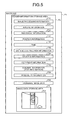
- FIG. 5 is a schematic diagram illustrating an example of the structure of the image file.
- An image file F 1 illustrated in FIG. 5 has a header information storage area F 2 that stores therein meta information of image data (meta information) as header information in a format compliant to the exchangeable image file format (Exif) and an image data storage area F 3 that stores therein the image data. Further, in the image file F 1 , thumbnail image data F 30 (JPEG format) of the image data are recorded.
- At least image processing information F 20 , imaging information F 21 , biological information F 22 , position information F 23 , time F 24 , distance distribution information F 25 , device ID information F 26 , copyright information F 27 , comment information F 28 , and possibility information F 29 are stored (recorded) as meta information.
- the meta information includes: additional change information that is able to be additionally recorded with new information or changed in its original information by another external device; and possibility information that sets whether or not the additional recording of the new information or change in the original information by the another external device is possible.
- the additional change information is the image processing information F 20 , the imaging information F 21 , the biological information F 22 , the position information F 23 , the time F 24 , the distance distribution information F 25 , the device ID information F 26 , the copyright information F 27 , and the comment information F 28 .
- the possibility information is the possibility information F 29 .
- the image processing information F 20 records therein an image processing parameter for developing the image data.
- the imaging information F 21 records therein a focal distance, a focal position, a diaphragm value, an exposure value, an ISO sensitivity, a data size of image data, a white balance, a shutter speed, and the like of the imaging unit 101 upon imaging of the image data by the imaging apparatus 100 .
- the biological information F 22 records therein biological information of the shooter or the subject detected by the biological information detection unit 107 .
- the position information F 23 records therein the position information acquired by the position acquiring unit 102 .
- the time F 24 records therein a shooting time at which the imaging apparatus 100 images the image data.
- the distance distribution information F 25 records therein a distribution of distance of a predetermined pixel row of the image corresponding to the image data, the distance being from the imaging apparatus 100 to the subject.
- the device ID information F 26 records therein device identification information, a manufacturing number, and the like, which represent identification information of the imaging apparatus 100 .
- the copyright information F 27 records therein information on an owner of the imaging apparatus 100 .
- the comment information F 28 records therein: text data such as a title of an image or a comment, which is displayed on a news feed when the image file F 1 is transmitted to the SNS server 200 or the like; related image data related to the image displayed on the news feed; and advertisement information, an icon, and the like, which are associated with the image displayed on the news feed.
- the possibility information F 29 records therein: prohibition information related to a state of a prohibition flag that sets whether or not additional recording of new information or change, with respect to each meta information in the header information storage area F 2 and image data storage area F 3 , by the portable device 300 when the image file is transmitted to the SNS server 200 is possible; information related to possibility of resizing of the image data; and resize limitation information (for example, resize limitation information, an image data compressibility, and a reduction rate of the image data) of the image data upon resizing of the image data by the SNS server 200 and/or portable device 300 .
- the image data F 31 are stored.
- FIG. 5 in order to simplify the description, schematic illustration is made by using an image corresponding to the image data of the image data F 31 , but in the actual image data F 31 , a data row of the image data is stored.
- the image file F 1 is recorded in the image data recording unit 108 b.
- the connection destination information recording unit 108 c records therein: identification information (IP address) of the imaging apparatus 100 necessary in performing wireless communications with the SNS server 200 via the network “N”, a password corresponding to the identification information, an account for transmitting the image file to the SNS server 200 , an IP address of the SNS server 200 , and the like.
- the communication unit 109 transmits the image file by performing wireless communications with the SNS server 200 , according to predetermined wireless communication standards.
- the predetermined wireless communication standards are IEEE 802.11b, IEEE 802.11n, and the like. In this embodiment, any of the wireless communication standards is applicable.
- the communication unit 109 is configured by using a communication device for performing bidirectional communications of various information such as the image file and the contents data with the SNS server 200 via the network “N”.
- the communication device is configured of an antenna that transmits and receives a radio signal to and from another device, a transmitting and receiving circuit that performs a demodulation process on the signal received by the antenna and a modulation process on a signal transmitted, and the like.
- the communication unit 109 periodically transmits a communication signal including identification information (device ID) informing a presence thereof when the imaging apparatus 100 is activated. Further, the communication unit 109 receives the communication signal transmitted from the SNS server 200 to return from a stop state or standby state and establishes communications with the SNS server 200 . Furthermore, the communication unit 109 returns from the stop state or standby state if the mode of the imaging apparatus 100 is switched over, for example, from the shooting mode to the playback mode or communication mode.
- the communication unit 109 may be provided in a recording medium, such as a memory card, which is inserted from outside of the imaging apparatus 100 . Further, the communication unit 109 may be provided in an accessory attached to the imaging apparatus 100 via a hot shoe.
- the control unit 110 comprehensively controls operations of the imaging apparatus 100 by performing transfer or the like of instructions and data corresponding to respective units forming the imaging apparatus 100 according to the instruction signal input from the input unit 103 , the position signal input from the touch panel 105 , or the like.
- the control unit 110 is configured by using a central processing unit (CPU) or the like.
- the control unit 110 has: an image processing unit 110 a ; a face detection unit 110 b ; a distance distribution detection unit 110 c ; a meta information generating unit 110 d ; a meta information adding unit 110 e ; an imaging control unit 110 f ; a possibility information generating unit 110 g ; an image file generating unit 110 h ; a display control unit 110 i ; and a communication control unit 110 j.
- the image processing unit 110 a acquires the image data generated by the imaging unit 101 or the image data (RAW data or compressed image data) recorded in the recording unit 108 , and generates image data (processed image data) obtained by performing various image processing on the acquired image data.
- the image processing unit 110 a is configured by using an image processing engine.
- the face detection unit 110 b detects, by pattern matching, a face of a person included in an image corresponding to the image data generated by the imaging unit 101 . Specifically, after detecting a position of the face in the image by using the pattern matching, the face detection unit 110 b detects positions of features of the face, such as eyes, a nose, a mouth, and the like, to thereby detect the position of the face, a size (area) of the face, a direction of the face, an angle (inclination) of the face, and the like. Further, the face detection unit 110 b detects sizes of the eyes, nose, mouth, and face as feature points of the face, if the face is detected in the image. The face detection unit 110 b may detect a face of an animal, such as a dog or a cat, besides the face of the person. Further, the face detection unit 110 b may detect the face of the person by using a known technique other than the pattern matching.
- the distance distribution detection unit 110 c detects distance distribution information indicating a distribution of distance from the imaging apparatus 100 to the subject with reference to a predetermined pixel row in an image corresponding to image data. Specifically, the distance distribution detection unit 110 c detects the distance distribution information from the imaging apparatus 100 to the subject by detecting a distance of each of a plurality of focus points.
- the distance distribution information may be information acquired when focusing of the imaging apparatus 100 is performed, and even if the distance distribution information is focus point position information, the distance distribution information is relative comparison information. Further, the distance distribution detection unit 110 c does not need to accurately measure a distance and may just be able to determine a perspective relation. Specifically, the distance distribution detection unit 110 c may just be able to determine a landscape and a close point.
- a poster or the like may be determined to be at a close distance rather than a long distance for detection, even if it is of a landscape.
- the focusing is generally of a mountain climbing method or phase difference method, but a facial size information or blur information may be used.
- the meta information generating unit 110 d generates a plurality of pieces of meta information related to the image data generated by the imaging unit 101 . Specifically, the meta information generating unit 110 d generates, when the imaging unit 101 generates the image data, the imaging information of the imaging unit 101 , the image processing information by the image processing unit 110 a , the biological information detected by the biological information detection unit 107 , the position information acquired by the position acquiring unit 102 , the time from the clock 106 , the distance distribution information detected by the distance distribution detection unit 110 c , the device ID information, and the copyright information, as the pieces of meta information.
- the meta information adding unit 110 e additionally records, as comment information of the meta information, text data input via the touch panel 105 when an input screen for inputting text data is displayed on an image displayed by the display unit 104 .
- the imaging control unit 110 f performs control to start still image operation in the imaging apparatus 100 , when the release signal is input from the release switch 103 b .
- a shooting operation in the imaging apparatus 100 refers to an operation of performing a predetermined process by the signal processing unit 101 c and the image processing unit 110 a on the image data output by the imaging element 101 b.
- the possibility information generating unit 110 g generates possibility information that sets whether or not additional recording of new information or changing of original information by the portable device 300 with respect to each of the plurality of pieces of meta information when each of the plurality of pieces of meta information is transmitted to the SNS server 200 is possible. Specifically, the possibility information generating unit 110 g generates possibility information setting a prohibition flag prohibiting additional recording of new information or changing of original information, with respect to a piece of meta information selected according to the selection signal selecting the piece of meta information input from the input unit 103 or the position signal input from the touch panel 105 when the display unit 104 is displaying the plurality of pieces of meta information.
- the image file generating unit 110 h generates the image file by associating: the meta information generated by the meta information generating unit 110 d , and the image data generated by the imaging unit 101 and subjected to the predetermined process by the signal processing unit 101 c and the image processing unit 110 a ; and the possibility information generated by the possibility information generating unit 110 g , and records the image file in the image data recording unit 108 b .
- the image file generating unit 110 h generates the image file according to the above described image file format of FIG. 5 .
- the display control unit 110 i controls a display mode of the display unit 104 . Further, the display control unit 110 i causes the display unit 104 to display various information of the imaging apparatus 100 .
- the communication control unit 110 j refers to the connection destination information recorded in the connection destination information recording unit 108 c and causes the communication unit 109 to transmit the image file via the network “N” to the specified SNS server 200 , if the instruction signal input from the input unit 103 and instructing the transmission of the image file to the SNS server 200 or the position signal input from the touch panel 105 is input.
- FIG. 6 is a block diagram illustrating a functional configuration of the SNS server 200 .
- the SNS server functions as a server according to an embodiment of the present invention.
- the SNS server 200 illustrated in FIG. 6 includes a communication unit 201 , an image database 202 , and an SNS server control unit 203 .
- the communication unit 201 receives or transmits the image file by performing communications with any of the imaging apparatus 100 and the portable device 300 , according to a predetermined communication standard.
- the image database 202 records therein the image file received via the communication unit 201 .
- the image database 202 is configured by using a recording medium such as an SDRAM, a flash memory, and a hard disk record.
- the SNS server control unit 203 is configured by using a CPU or the like, and transmits, according to an access signal input from any of the imaging unit 101 and the portable device 300 via the communication unit 201 , a specified page of a browser (image file).
- the SNS server control unit 203 has an access determination unit 203 a , a meta information adding unit 203 b , a data size determination unit 203 c , a resizing unit 203 d , a display control unit 203 e , and a communication control unit 203 f.
- the access determination unit 203 a determines a device from which the access signal has been received via the network “N” and communication unit 201 . For example, the access determination unit 203 a determines whether or not the access signal has been received from the portable device 300 .
- the meta information adding unit 203 b additionally records this additional data in the image file specified from the portable device 300 .
- the meta information adding unit 203 b additionally records in the image file as the meta information, any of: comment data with respect to an image (specified page) corresponding to the image data of the image file specified from the portable device 300 ; related image data associated with the image data; network address information of the related image data associated with the image data; and advertisement information (advertisement image data or advertisement moving image data) associated with the image data.
- the data size determination unit 203 c determines whether or not a volume of the image file planned to be additionally recorded with new meta information by the meta information adding unit 203 b will exceed a prescribed amount set beforehand if the meta information adding unit 203 b is to additionally record the new meta information in the image file. This prescribed amount is set according to a communication standard with prescribed communication speed and data size.
- the resizing unit 203 d executes a resize process on the image data stored in the image file and stores the resized image data in the image database 202 , if the data size determination unit 203 c determines that the volume of the image file will exceed the prescribed amount. For example, the resizing unit 203 d executes a resize process of compressing or reducing the image data stored in the image file.
- the display control unit 203 e controls a display mode of a specified page of a specified browser, according to the access signal input from any of the imaging unit 101 and portable device 300 via the network “N” and communication unit 201 .
- the display control unit 203 e displays the image corresponding to the image data of the image file in the specified page specified according to the access signal.
- the communication control unit 203 f controls connection of the imaging apparatus 100 or portable device 300 accessed via the network “N” and transmits the image file in the specified image database 202 .
- FIG. 7 is a block diagram illustrating a functional configuration of the portable device 300 .
- the portable device 300 illustrated in FIG. 7 includes a communication unit 301 , a display unit 302 , a touch panel 303 , an operating unit 304 , a recording unit 305 , and a portable device control unit 306 .
- the communication unit 301 receives or transmits the image file by performing communications with any of the imaging apparatus 100 and the SNS server 200 , according to a predetermined communication standard.
- the display unit 302 displays the image corresponding to the image data.
- the display unit 302 is configured by using a display panel formed of a liquid crystal, organic EL, or the like. Further, the display unit 302 displays an image of a specified page specified when accessing the SNS server 200 via the network “N” and communication unit 301 .
- the touch panel 303 is provided on a display screen of the display unit 302 .
- the touch panel 303 detects a touch of a finger, a touch pen, or any other object from outside, and outputs to the portable device control unit 306 a position signal corresponding to this detected touch position. Further, the touch panel 303 detects a position touched by a user based on information displayed by the display unit 302 and receives input of an instruction signal instructing an operation to be performed by the portable device 300 according to this detected touch position.
- the operating unit 304 receives input of a selection signal selecting any of various parameters of the portable device 300 and personal authentication information.
- the operating unit 304 is configured by using various switches.
- the recording unit 305 records therein the image data and various programs executed by the portable device 300 . Further, the recording unit 305 records therein: identification information of the portable device 300 necessary in performing wireless communications with the SNS server 200 ; a password corresponding to the identification information; and an account, a password, and an IP address of the SNS server 200 , which are for transmitting an access to the SNS server 200 .
- the recording unit 305 is configured by using a semiconductor memory such as a flash memory or a DRAM.
- the portable device control unit 306 is configured by using a CPU or the like, and comprehensively controls operations of the portable device 300 by performing transfer or the like of instructions and data corresponding to respective units forming the portable device 300 according to the positions signal input from the touch panel 303 or instruction signal input from the operating unit 304 .
- the portable device 400 has a configuration that is the same as that of the above described portable device 300 , and thus description of the configuration of the portable device 400 will be omitted.
- the image file is able to be browsed by being transmitted to the SNS server 200 by the imaging apparatus 100 via the network “N” and the portable device 300 accessing the SNS server 200 .
- FIG. 8 is a flow chart illustrating an outline of the process executed by the image browsing system 1 .
- the imaging apparatus 100 executes imaging (step S 1 ), and transmits an image file to the SNS server 200 (step S 2 ).
- step S 3 if the image file is received via the network “N” from the imaging apparatus 100 (step S 3 : Yes), the SNS server 200 stores the image file in the image database 202 (step S 4 ). In contrast, if the SNS server 200 has not received the image file via the network “N” from the imaging apparatus 100 (step S 3 : No), the later described step S 6 is executed.
- the portable device 300 accesses the SNS server 200 (step S 5 ). Specifically, the portable device 300 accesses the SNS server 200 , if an icon to receive input of an instruction signal instructing to make an access to the SNS server 200 displayed by the display unit 302 is operated.
- step S 6 the SNS server 200 transmits to the portable device 300 a specified page according to the access from the portable device 300 (step S 7 ).
- step S 6 the SNS server 200 ends this process.
- the portable device 300 causes the display unit 302 to display the specified page transmitted from the SNS server 200 (step S 8 ), and a comment on an image in the specified page is input via the touch panel 303 or operating unit 304 (step S 9 ).
- FIG. 9 is a diagram illustrating an example of the specified page displayed by the display unit 302 of the portable device 300 .
- the portable device 300 causes the display unit 302 to display the specified page P 1 .
- an image W 1 On the specified page P 1 , an image W 1 , a title T 1 of the image W 1 as meta information of an image file of the image W 1 , a shooting location T 2 of the image W 1 , a shooting time T 3 of the image W 1 (for example, a date and a shooting time), and news information T 4 where comments of other account users on the image W 1 are displayed along a time series, are displayed.
- the user of the portable device 300 additionally records a comment on the image W 1 of the specified page P 1 via the touch panel 303 . In this case, if a prohibition flag prohibiting additional recording of a comment is recorded in an image file of the specified page P 1 , the SNS server 200 transmits to the portable device 300 a warning that comments cannot be additionally recorded.
- step S 10 the meta information adding unit 203 b additionally records the comment in the meta information of the image file corresponding to the specified page (step S 11 ).
- step S 10 no comment is additionally recorded on the specified page from the portable device 300 (step S 10 : No)
- step S 15 the SNS server 200 proceeds to later described step S 15 .
- Step S 11 if the data size determination unit 203 c determines that a volume of the image file is over a prescribed amount set beforehand (step S 12 : Yes), the resizing unit 203 d executes a compression process of image data of the image file (step S 13 ). Thereby, the SNS server 200 is able to maintain the volume of the image file constant and thus in transmission of the image file, transmission of the image file is possible without delay. In contrast, if the data size determination unit 203 c does not determine that the image file is over the capacity prescribed beforehand (step S 12 : No), the SNS server 200 proceeds to later described step S 15 .
- the portable device 300 transmits an instruction signal instructing to download the specified page via the network “N” (step S 14 ).
- step S 15 if the SNS server 200 receives the instruction signal from the portable device 300 (step S 15 : Yes), the SNS server 200 transmits to the portable device 300 an image file corresponding to the instruction signal (step S 16 ). After step S 16 , the image browsing system 1 ends this process. In contrast, if the instruction signal is not received from the portable device 300 (step S 15 : No), the image browsing system 1 ends this process.
- FIG. 10 is a flow chart illustrating an outline of the process executed by the imaging apparatus 100 .
- step S 101 a case in which the imaging apparatus 100 is set to the shooting mode
- the imaging apparatus 100 executes a shooting mode process of imaging a subject and generating image data (step S 102 ). Details of the shooting mode process will be described later.
- step S 103 determines whether the power switch 103 a is operated and power of the imaging apparatus 100 is turned off.
- the imaging apparatus 100 ends this process.
- the power switch 103 a is not operated and the power of the imaging apparatus 100 is not turned off (step S 103 : No)
- the imaging apparatus 100 returns to step S 101 .
- step S 101 if the imaging apparatus 100 is not set to the shooting mode (step S 101 : No) and the imaging apparatus 100 is set to the playback mode (step S 104 : Yes), the imaging apparatus 100 executes playback display of the image data stored in the image file recorded in the image data recording unit 108 b or a playback mode process of transmitting the image file to the SNS server 200 (step S 105 ). Details of the playback mode process will be described later. After step S 105 , the imaging apparatus 100 proceeds to step S 103 .
- step S 101 if the imaging apparatus 100 is not set to the shooting mode (step S 101 : No), the imaging apparatus 100 is not set to the playback mode (step S 104 : No), and further the imaging apparatus 100 is set to a communication destination setting mode (step S 106 : Yes), the imaging apparatus 100 sets a communication destination address, an ID, and a password, according to an instruction signal input from the touch panel 105 or input unit 103 (step S 107 ). After step S 107 , the imaging apparatus 100 proceeds to step S 103 .
- step S 106 if the imaging apparatus 100 is not set to the communication destination setting mode (step S 106 : No), the imaging apparatus 100 proceeds to step S 108 .
- step S 108 the imaging apparatus 100 receives an image file via the communication unit 109 (step S 109 ), and records the image file in the image data recording unit 108 b (step S 110 ). After step S 110 , the imaging apparatus 100 proceeds to step S 103 .
- step S 108 if there is no access to the imaging apparatus 100 from the outside via the network “N” (step S 108 : No), the imaging apparatus 100 proceeds to step S 103 .
- FIG. 11 is a flow chart illustrating an outline of the shooting mode process.
- the imaging control unit 110 f causes the imaging unit 101 to execute shooting (step S 201 ).
- the display control unit 110 i causes the display unit 104 to display a live view image corresponding to image data generated by the imaging unit 101 (step S 202 ).
- a shooter U 1 performs shooting while adjusting by using the touch panel 105 or input unit 103 , by checking a live view image W 1 displayed by the display unit 104 of the imaging apparatus 100 , any of a composition and shooting conditions with respect to a subject, for example, a diaphragm value, an exposure value, an ISO sensitivity, a white balance, a focus point position, a focal distance, a shutter speed, and a gradation.
- the meta information generating unit 110 d acquires a feature point of the face detected by the face detection unit 110 b (step S 204 ). For example, as illustrated in FIG. 13 , if the face detection unit 110 b detects a face in the live view image W 10 , the meta information generating unit 110 d acquires a feature point of the detected face. When this is done, the display control unit 110 i causes a frame Z 1 corresponding to a face area including the face detected by the face detection unit 110 b to be superimposed on the live view image W 10 for display by the display unit 104 . After step S 204 , the imaging apparatus 100 proceeds to step S 205 .
- step S 203 if the face detection unit 110 b does not detect a face in the live view image W 10 (step S 203 : No), the imaging apparatus proceeds to step S 205 .
- the meta information generating unit 110 d acquires a time from the clock 106 (step S 205 ), and acquires position information from the position acquiring unit 102 (step S 206 ).
- the meta information generating unit 110 d acquires biological information of the shooter detected by the biological information detection unit 107 (step S 207 ).
- the distance distribution detection unit 110 c detects distance distribution information representing a distribution of distance from the imaging apparatus 100 to the subject with reference to a line in a predetermined horizontal direction of the live view image W 10 (step S 209 ).
- FIG. 14 is a diagram schematically illustrating an outline of a distance detection method of the distance distribution detection unit 110 c .
- a vertical axis represents distance from the imaging apparatus 100 to the subject
- a horizontal axis represents positions of respective pixels on the one line (line L 10 ) of the image.
- the distance distribution detection unit 110 c detects a distance distribution from the imaging apparatus 100 to the subject by scanning one line in a predetermined horizontal direction of the live view image W 10 , for example, one line (pixel row) including the frame Z 1 corresponding to the face area detected by the face detection unit 110 b . Specifically, as illustrated in FIG. 14 at (a), the distance distribution detection unit 110 c detects distance distribution information L 11 ((b) of FIG. 14 ) from the imaging apparatus 100 to the subject, by scanning the line L 10 on the live view image W 10 .
- the imaging control unit 110 f causes the imaging unit 101 to execute shooting. Specifically, the imaging control unit 110 f causes the imaging unit 101 to output image data by driving the imaging unit 101 .
- the image file generating unit 110 h generates an image file associating the image data generated by the imaging unit 101 with the meta information generated by the meta information generating unit 110 d and records the image file in the image data recording unit 108 b (step S 211 ).
- the display control unit 110 i causes the display unit 104 to display an image corresponding to the image data generated by the imaging unit 101 (step S 212 ).
- step S 213 determines whether a predetermined time period, for example, three seconds, has passed since the display unit 104 displayed the image.
- a predetermined time period for example, three seconds
- the imaging apparatus 100 proceeds to step S 214 .
- the imaging apparatus 100 returns to step S 212 .
- step S 214 the display control unit 110 i causes the display of the image by the display unit 104 to be ended.
- the imaging apparatus 100 returns to a main routine of FIG. 10 .
- step S 208 if there is no shooting operation via the release switch 103 b (step S 208 : No), the imaging apparatus 100 returns to the main routine of FIG. 10 .
- FIG. 15 is a flow chart illustrating an outline of the playback mode process.
- the display control unit 110 i causes the display unit 104 to display a list of respective images of a plurality of sets of image data recorded in the image data recording unit 108 b (step S 301 ).
- step S 302 determines whether an image is selected from the list of images displayed by the display unit 104 via the input unit 103 or touch panel 105 (step S 302 : Yes).
- the display control unit 110 i causes the display unit 104 to display the selected image in full screen (step S 303 ).
- step S 303 the imaging apparatus 100 proceeds to later described step S 304 .
- step S 302 No
- the imaging apparatus 100 proceeds to later described step S 305 .
- step S 304 if an instruction signal instructing a change in the image displayed by the display unit 104 is input by the input unit 103 or touch panel 105 (step S 304 : Yes), the imaging apparatus 100 returns to step S 303 . In contrast, if no instruction signal instructing a change in the image displayed by the display unit 104 is input via the input unit 103 or touch panel 105 (step S 304 : No), the imaging apparatus 100 proceeds to step S 305 .
- step S 305 If an instruction signal instructing the playback mode to be ended is input from the input unit 103 (step S 305 : Yes), the imaging apparatus 100 returns to the main routine of FIG. 10 . In contrast, if the instruction signal instructing the playback mode to be ended is not input from the input unit 103 (step S 305 : No), the imaging apparatus 100 proceeds to step S 306 .
- the control unit 110 determines whether or not the share switch 103 c is operated by the shooter. Specifically, as illustrated in FIG. 16 , the control unit 110 determines whether or not an instruction signal instructing upload of the image file in order to allow browsing of the image file by another device via the SNS server 200 is input from the share switch 103 c by the shooter operating the share switch 103 c . If the control unit 110 determines that the share switch 103 c has been operated by the shooter (step S 306 : Yes), the imaging apparatus 100 proceeds to later described step S 307 . In contrast, if the control unit 110 determines that the share switch 103 c has not been operated by the shooter (step S 306 : No), the imaging apparatus 100 returns to step S 302 .
- the display control unit 110 i causes the display unit 104 to display a tag selection input screen. Specifically, as illustrated in FIG. 17 , the display control unit 110 i causes the display unit 104 to display a tag selection input screen H 1 . In that case, the display control unit 110 i causes the display unit 104 to display the selected image W 1 after reducing the selected image W 1 . Further, the display control unit 110 i causes the display unit 104 to display a news tag icon A 10 , a select-prohibition-of-change icon A 11 , and a transmit icon R 12 by superimposing them on the tag selection input screen H 1 .
- the news tag icon A 10 receives input of an instruction signal instructing a keyboard for inputting a title displayed in a news feed to be displayed when the image file is transmitted to the SNS server 200 .
- the select-prohibition-of-change icon A 11 receives input of an instruction signal instructing a selection screen for selecting meta information prohibiting change or additional recording from the meta information stored in the image file of the selected image W 1 to be displayed.
- the transmit icon A 12 receives input of an instruction signal for transmitting the image file of the selected image W 1 to the SNS server 200 .
- the display control unit 110 i causes the display unit 104 to perform display by superimposing a key board on the tag selection input screen H 1 (step S 309 ). Specifically, as illustrated in FIG. 18A and FIG. 18B , if the shooter touches the new tag icon A 10 , the display control unit 110 i causes the display unit 104 to display the keyboard K 1 ( FIG. 18A ⁇ FIG. 18B ).
- the meta information generating unit 110 d generates a news tag according to input on the keyboard K 1 via the touch panel 105 (step S 310 ).
- the meta information generating unit 110 d generates, as meta information of the title of the news feed, the input on the key board K 1 via the touch panel 105 by the shooter, which is “earthquake disaster wall damage” ( FIG. 18B ⁇ FIG. 18C ).
- the display control unit 110 i causes the display unit 104 to display a determine icon A 13 for receiving input of an instruction signal instructing determination of the title.
- the display control unit 110 i may cause a conversion icon for converting a letter or number selected via the key board K 1 to be displayed in the keyboard K 1 or tag selection input screen H 1 .
- step S 311 the meta information adding unit 110 e additionally records the meta information of the news feed generated by the meta information generating unit 110 d in comment information in a header information storage area of the image file (step S 312 ).
- step S 312 the imaging apparatus 100 returns to step S 307 .
- step S 311 No
- the imaging apparatus 100 returns to step S 309 .
- step S 308 if the news tag icon A 10 is not selected (step S 308 : No) and the select-prohibition-of-change icon A 11 is selected (step S 313 : Yes), the display control unit 110 i causes the display unit 104 to display a list of meta information (step S 314 ). Specifically, as illustrated in FIG. 19A and FIG. 19B , the display control unit 110 i causes the display unit 104 to display the list of meta information. For example, as illustrated in FIG.
- the display control unit 110 i causes the display unit 104 to display, as meta information, at least a title T 11 of the news tag (NWSTG), a shooting location T 12 , a shooting time T 13 , a shooter T 14 , an image size T 15 (volume information), and a file size T 16 .
- the meta information to be displayed may be set as appropriate. If a large degree of freedom is given to this file size, treatment thereof, such as transmission and reception or processing thereof, becomes difficult, and thus a certain limitation thereon is preferable. Therefore when additional recording of information is characteristic as in the present invention, means for making this file size to be within a certain range become important.
- an image data portion may be resized, or information that is deletable may be deleted.
- Information on whether the information is deletable is recorded in the image file as the possibility information F 29 .
- an image requires about one mega byte if printing is postulated, but for viewing with a compact portable device, about ten kilo bytes are sufficient.
- reduction (resizing) to that extent is not preferable and there is limitation on resizing according to its use, and thus such information may be recorded in the possibility information F 29 of the image file.
- imaging apparatus 100 may perform control to make such setting by a predetermined program.
- the possibility information generating unit 110 g generates a prohibition flag prohibiting change or additional recording of meta information by the portable device 300 according to input on a plurality of pieces of meta information via the touch panel 105 and additionally records the prohibition flag in possibility information in a header information storage area of the image file (step S 315 ).
- the possibility information generating unit 110 g generates a prohibition flag prohibiting change in the image size T 15 , if the image size T 15 is touched, and additionally records the prohibition flag in the possibility information F 29 of the image file ( FIG. 19A ⁇ FIG. 19B ).
- the display control unit 110 i causes the display unit 104 to display each meta information for which the prohibition flag has been generated by the possibility information generating unit 110 g in a blackened form.
- the possibility information generating unit 110 g has been described with an example in which the image size T 15 is the meta information, but a prohibition flag prohibiting change of the shooting location T 12 , the shooting time T 13 , and the shooter T 14 may be generated and additionally recorded in the possibility information F 29 of the image file.
- private information of the shooter for example, the shooting location T 12 , the shooting time T 13 , and the shooter T 14 is preventable from being modified by another user.
- step S 316 Yes
- step S 316 No
- step S 314 the imaging apparatus 100 returns to step S 314 .
- step S 308 if the news tag icon A 10 is not selected (step S 308 : No) and the select-prohibition-of-change icon A 11 is not selected (step S 313 : No), the imaging apparatus 100 proceeds to step S 317 .
- step S 317 if the transmit icon A 12 is selected (step S 317 : Yes), the image file is transmitted to the SNS server 200 (step S 318 ). After step S 318 , the imaging apparatus 100 returns to step S 305 .
- step S 317 if the transmit icon A 12 is not selected (step S 318 : No), the imaging apparatus 100 proceeds to step S 319 .
- step S 319 Yes
- the imaging apparatus 100 returns to step S 305 .
- step S 319 No
- the imaging apparatus 100 returns to step S 307 .
- FIG. 20 is a flow chart illustrating an outline of the process executed by the SNS server 200 .
- step S 401 a case in which data are received from the imaging apparatus 100 (step S 401 : Yes) will be described.
- the SNS server control unit 203 receives an image file transmitted from the imaging apparatus 100 via the communication unit 201 (step S 402 ).
- the SNS server control unit 203 stores the image file in a specified page of the image database 202 (step S 403 ).
- the meta information adding unit 203 b tags an address on the network and additionally records the tagged address in comment information of the image file (step S 404 ).
- the SNS server 200 returns to step S 401 .
- step S 401 if data are not received from the imaging apparatus 100 (step S 401 : No) and there is an access to a browser from the portable device 300 (step S 405 : Yes), the display control unit 203 e causes the portable device 300 to display a specified page and meta information corresponding to the access from the portable device 300 (step S 406 ).
- step S 407 if there is a switch over instruction from the portable device 300 to switch over to another page (step S 407 : Yes), the display control unit 203 e causes the portable device 300 to display the another page and meta information corresponding to a switch over signal from the portable device 300 (step S 408 ).
- step S 409 Yes
- step S 409 No
- step S 410 the SNS server 200 proceeds to step S 410 .
- step S 410 if there is an instruction to select an image from the portable device 300 (step S 410 : Yes), the SNS server 200 proceeds to later described step S 411 . In contrast, if there is no instruction to select an image from the portable device 300 (step S 410 : No), the SNS server 200 returns to step S 407 .
- step S 407 if there is no change over instruction to switch over to another page from the portable device 300 (step S 407 : No), the SNS server 200 proceeds to step S 409 .
- step S 411 if comment data to be additionally recorded with the image are received from the portable device 300 via the network “N” (step S 411 : Yes), the SNS server 200 proceeds to later described step S 412 . In contrast, if the comment data to be additionally recorded with the image from the portable device 300 is not received via the network “N” (step S 411 : No), the SNS server 200 proceeds to later described step S 417 .
- the data size determination unit 203 c determines whether or not a data volume of the image file exceeds a prescribed amount when the comment data received from the portable device 300 are additionally recorded in the image file. If the data size determination unit 203 c determines that the volume of the image file exceeds the prescribed amount when the comment data received from the portable device 300 are additionally recorded in the image file (step S 412 : Yes) and compression (resizing) of image data of the image file is possible (step S 413 : Yes), the resizing unit 203 d compresses the image data of the image file (step S 414 ). This compression is supposed to be decimation or compressibility increase and it has been already described that limitation may be placed on this resizing.
- the meta information adding unit 203 b tags the comment data and stores the tagged comment data in the image file (step S 415 ). After step S 415 , the SNS server 200 returns to step S 401 .
- step S 412 if the data size determination unit 203 c determines that the volume of the image file exceeds the prescribed amount when the comment data received from the portable device 300 are additionally recorded in the image file (step S 412 : Yes) and compression of the image data is not possible, for example, the prohibition flag prohibiting change in data size of the image data is set in the meta information of the image file or a data size of the image data is less than a predetermined value (step S 413 : No), the display control unit 203 e transmits to the portable device 300 a warning that the comment cannot be additionally recorded in a news tag of the selected image (step S 416 ). After step S 416 , the SNS server 200 returns to step S 401 .
- step S 412 if the data size determination unit 203 c determines that the volume of the image file does not exceed the prescribed amount when the comment data received from the portable device 300 are additionally recorded in the image file (step S 412 : No), the SNS server 200 proceeds to step S 415 .
- step S 411 if the comment data to be additionally recorded with the image are not received from the portable device 300 (step S 411 : No), the SNS server 200 proceeds to step S 417 .
- step S 417 if the image file is to be transmitted to the portable device 300 (step S 417 : Yes), the communication control unit 203 f causes the communication unit 201 to transmit the specified image file to the specified address (step S 418 ). After step S 418 , the SNS server 200 returns to step S 401 .
- step S 417 if the image file is not to be transmitted to the portable device 300 (step S 417 : No), the SNS server 200 returns to step S 401 .
- step S 401 if data are not received from the imaging apparatus 100 (step S 401 : No) and there is no access from the portable device 300 to the browser (step S 405 : No), the SNS server 200 returns to step S 401 .
- the image file generating unit 110 h of the imaging apparatus 100 generates the image file associating the image data generated by the imaging unit 101 , the plurality of pieces of meta information related to the image data generated by the meta information generating unit 110 d , and the possibility information generated by the possibility information generating unit 110 g with one another, while being able to additionally record information, treatment thereof is easily and simply possible, and an image file is able to be transmitted without delay according to a communication standard with a prescribed communication speed.
- the possibility information generating unit 110 g of the imaging apparatus 100 generates the prohibition flag prohibiting the additional recording of the new information or the change in the original information by the portable device 300 for the meta information selected from the plurality of pieces of meta information displayed by the display unit 104 , based on the selection signal input from the input unit 103 or touch panel 105 , and additionally records the prohibition flag in the possibility information of the image file.
- the shooter is able to prevent modification of desired meta information of an image file when transmitting the image file to the SNS server 200 to share the image file with another user.
- the resizing unit 203 d of the SNS server 200 resizes the image data in the image file and thus the image file is able to be transmitted without delay according to a communication standard with a prescribed communication speed.
- An imaging apparatus has a configuration that is the same as that of the imaging apparatus according to the above described first embodiment, and only a shooting mode process thereof is different.
- an SNS server has a configuration that is the same as that of the SNS server according to the above described first embodiment, and only a process executed thereby is different. Accordingly, hereinafter, after describing the shooting mode process executed by the imaging apparatus, the process executed by the SNS server will be described. Configurations that are the same as those of the imaging apparatus 100 and the SNS server 200 according to the above described first embodiment will be appended with the same symbols and description thereof will be omitted.
- FIG. 21 is a flow chart illustrating an outline of the shooting mode process executed by the imaging apparatus 100 .
- the imaging control unit 110 f causes the imaging unit 101 to execute shooting (step S 501 ).
- the display control unit 110 i causes the display unit 104 to display a live view image corresponding to image data generated by the imaging unit 101 (step S 502 ).
- a shooter U 1 performs shooting while adjusting, by checking a live view image W 20 displayed by the display unit 104 of the imaging apparatus 100 , any of a composition and shooting conditions with respect to a subject.
- Step S 503 to step S 507 correspond respectively to steps S 203 to step S 207 of FIG. 11 .
- step S 508 if the share switch 103 c is operated and an instruction signal to refer to an image file posted to the SNS server 200 in the past is input (step S 508 : Yes), the display control unit 110 i causes the display unit 104 to display a reference image (step S 509 ). Specifically, as illustrated in FIG. 23 , the display control unit 110 i causes the display unit 104 to display a thumbnail image of each image file recorded in the image data recording unit 108 b and transmitted to the SNS server 200 , for example, a thumbnail image WS 1 , a thumbnail image WS 21 , and a thumbnail image WS 22 , as reference images (related images).
- the display control unit 110 i reduces the display area of the live view image W 20 to be displayed by the display unit 104 . Further, the display control unit 110 i causes the display unit 104 to display a reference icon A 30 indicating that transition to reference shooting has taken place.
- the meta information adding unit 110 e executes a tag take-over process (step S 511 ). Specifically, as illustrated in FIG. 24 , the meta information adding unit 110 e executes a tag take-over process of recording, into a header information storage area F 2 of an image file F 10 recording image data planned to be shot, related image data information F 11 related to the image data.
- the related image data information F 11 records therein related image data associated with the image data, and meta information of the related image, for example, an address of the SNS server 200 , a specified page, a title on a news feed, comment data additionally recorded from another account, and the like.
- step S 508 if the share switch 103 c is not operated and the instruction signal for referring to the image file posted to the SNS server 200 in the past is not input (step S 508 : No), the imaging apparatus 100 proceeds to later described step S 512 .
- step S 510 if a reference image is not selected via the touch panel 105 from the plurality of reference images displayed by the display unit 104 (step S 510 : No), the imaging apparatus 100 returns to step S 509 .
- Step S 512 to step S 518 correspond respectively to step S 208 to step S 214 of FIG. 11 .
- the imaging apparatus 100 returns to the main routine of FIG. 10 .
- FIG. 25 is a flow chart illustrating an outline of the process executed by the SNS server 200 .
- step S 601 and step S 602 correspond respectively to step S 401 and step S 402 of FIG. 20 .
- step S 603 if an image file received is of reference shooting (step S 603 : Yes), the image file is stored in a specified page of the image database 202 that is the same as that of the related image data (step S 604 ). After step S 604 , the SNS server 200 proceeds to step S 605 .
- step S 603 if the image file received is not of reference shooting (step S 603 : No), the SNS server 200 proceeds to step S 606 .
- Step S 605 corresponds to step S 404 of FIG. 20 . Further, step S 606 corresponds to step S 403 of FIG. 20 . Step S 607 and step S 608 correspond respectively to step S 405 and step S 406 of FIG. 20 .
- step S 609 if a specified page according to an access from the portable device 300 is of reference shooting (step S 609 : Yes), the display control unit 203 e causes the display unit 302 of the portable device 300 to display the specified page according to the access from the portable device 300 , meta information, and reference images together (step S 610 ). Specifically, as illustrated in FIG.
- the display control unit 203 e causes the display unit 302 of the portable device 300 to display a specified page P 2 , a title T 1 of the past meta information, a shooting location T 2 , a shooting time T 3 , news information T 4 , comments M 1 to M 3 written onto the specified page P 2 , a related image WS 20 , and meta information of the related image WS 20 together.
- a user of the portable device 300 is able to grasp intuitively a related image from a news feed where latest information is sequentially displayed in time series. Further, the user of the portable device 300 is able to shorten a retrieval time period for retrieving an image related to the related image WS 20 from a vast group of images on the news feed.
- the SNS server 200 proceeds to step S 611 .
- step S 609 if the specified page according to the access from the portable device 300 is not of reference shooting (step S 609 : No), the SNS server 200 proceeds to step S 611 .
- Step S 611 to step S 622 correspond respectively to step S 407 to step S 418 of FIG. 20 .
- the meta information adding unit 110 e of the imaging apparatus 100 additionally records, as the meta information, in the image file, any of the related image data associated with the image data, the address information on the network of the related image data associated with the image data, and the advertisement information associated with the image data.
- a user of the portable device 300 is able to grasp intuitively a related image from a news feed where latest information is sequentially displayed in time series.
- the display control unit 203 e associates the latest image on the specified page P 2 and causes the display unit 302 of the portable device 300 to perform the display thereof, but the reference image may be associated on another specified page and the display unit 302 of the portable device 300 may be caused to perform display thereof.
- the display control unit 203 e may cause the display unit 302 of the portable device 300 to display the referenced related image information on a specified page P 3 as a comment M 10 of the news information T 4 .
- a user of the portable device 300 is able to intuitively grasp information on a reference image displayed on a news feed in the past just by browsing the latest information on the news feed.
- the display control unit 203 e causes the display unit 302 of the portable device 300 to display a specified page associated with the related image information.
- the related image displayed on the newsfeed in the past is able to be visually checked by a simple and easy operation.
- a third embodiment will be described.
- a configuration of the control unit of the imaging apparatus according to the above described first embodiment is different, and a shooting mode process executed by the imaging apparatus is different. Therefore, hereinafter, after describing the configuration of the control unit of the imaging apparatus, the shooting mode process executed by the imaging apparatus will be described.
- Structural elements that are the same as those of the imaging apparatus 100 according to the above described first embodiment will be appended with the same symbols and description thereof will be omitted.
- FIG. 28 is a block diagram illustrating a functional configuration of the imaging apparatus according to the third embodiment.
- An imaging apparatus 500 illustrated in FIG. 28 includes a control unit 510 instead of the control unit 110 of the imaging apparatus 100 according to the above described first embodiment.
- the control unit 510 comprehensively controls operations of the imaging apparatus 500 by performing transfer or the like of instructions and data corresponding to respective units forming the imaging apparatus 500 according to the instruction signal input from the input unit 103 , the position signal input from the touch panel 105 , or the like.
- the control unit 510 is configured by using a CPU or the like.
- the control unit 510 has: the image processing unit 110 a ; the face detection unit 110 b ; the distance distribution detection unit 110 c ; the meta information generating unit 110 d ; the meta information adding unit 110 e ; the imaging control unit 110 f ; the possibility information generating unit 110 g ; the image file generating unit 110 h ; the display control unit 110 i ; the communication control unit 110 j ; a data size determination unit 510 a ; and a resizing unit 510 b.
- the data size determination unit 510 a determines, if the meta information adding unit 110 e is to additionally record meta information or image data to an image file, whether or not a volume of the image file planned to be additionally recorded with the meta information by the meta information adding unit 110 e will exceed a prescribed amount.
- the resizing unit 510 b executes, if the data size determination unit 510 a determines that the volume of the image data exceeds the prescribed amount, a resizing process of compressing or reducing image data stored in the image file and store them in the image database 202 .
- FIG. 29 is a flow chart illustrating an outline of the shooting mode process executed by the imaging apparatus 500 .
- step S 701 to step S 707 correspond respectively to step S 201 to step S 207 of FIG. 11 .
- step S 708 to step S 710 correspond respectively to step S 508 to step S 510 of FIG. 21 .
- the display control unit 110 i acquires a reference image file from the image data recording unit 108 b and causes the display unit 104 to display the reference image file. Specifically, as illustrated in FIG. 30 , the display control unit 110 i causes the display unit 104 to display a thumbnail image W 40 stored in the reference image file and causes a display area of a live view image W 1 to be reduced and displayed by the display unit 104 . Further, the display control unit 110 i causes the display unit 104 to display an additional-shooting-in-process icon A 40 indicating that the imaging apparatus 500 is in the process of additional shooting.
- Step S 712 to step S 714 correspond respectively to step S 208 to step S 210 of FIG. 11 .
- the meta information generating unit 110 d reproduces a reference image file corresponding to the thumbnail image W 40 being displayed by the display unit 104 .
- the data size determination unit 510 a determines whether or not a volume of the image file reproduced by the meta information generating unit 110 d exceeds a prescribed amount (step S 716 ). If the data size determination unit 510 a determines that the volume of the image file reproduced by the meta information generating unit 110 d has exceeded the prescribed amount (step S 716 : Yes), the imaging apparatus 500 proceeds to later described step S 717 . In contrast, if the data size determination unit 510 a determines that the volume of the image file reproduced by the meta information generating unit 110 d has not exceeded the prescribed amount (step S 716 : No), the imaging apparatus 500 proceeds to later described step S 720 .
- step S 717 if image data of the image file reproduced is compressible (step S 717 : Yes), the resizing unit 510 b performs compression (a resize process) of a data size of the image data of the reproduced image file (step S 718 ). After step S 718 , the imaging apparatus 500 proceeds to later described step S 720 .
- step S 717 if the image data of the reproduced image file is not compressible (step S 717 : No), the meta information generating unit 110 d acquires thumbnail image data stored in the reproduced image file (step S 719 ).
- the meta information generating unit 110 d tags the shot image data and regenerates an image file (step S 720 ).
- the image file generating unit 110 h generates an image file associating the image data generated by the imaging unit 101 with the meta information including the image data of the reproduced image file generated by the meta information generating unit 110 d or the thumbnail image data and records the image file in the image data recording unit 108 b (step S 721 ). Specifically, as illustrated in FIG. 31 , the image file generating unit 110 h generates an image file F 100 associating an image data F 32 generated by the imaging unit 101 with meta information including image data F 31 of the reproduced image file generated by the meta information generating unit 110 d and stores the image file F 100 in the image data recording unit 108 b.
- the display control unit 110 i causes the display unit 104 to display an image corresponding to the image data stored in the image file (step S 722 ). Specifically, as illustrated in FIG. 32 , the display control unit 110 i causes the display unit 104 to display the image W 1 corresponding to the image data generated by the imaging unit 101 and a related image W 20 that has been referenced. Further, the display control unit 110 i causes the display unit 104 to display some of respective meta information of the image W 1 and related image W 20 , for example, titles T 1 and T 10 , locations, and dates and times. Furthermore, the display control unit 110 i causes the display unit 104 to display a reference shooting result icon A 41 indicating that it is a shooting result of reference shooting.
- Step S 723 and step S 724 correspond respectively to step S 213 and step S 214 of FIG. 11 . Further, step S 725 to step S 727 correspond respectively to step S 208 to step S 210 of FIG. 11 .
- the resizing unit 510 b of the imaging apparatus 500 compresses (resizes) the image data in the image file, and thus an image file is able to be transmitted without delay according to a communication standard with a prescribed communication speed. Therefore, treatment of an image file is able to be made easy. For example, effects are demonstrated that a file size is able to be limited, recording is easy, treatment such as processing is easy, and transmission of an image file is possible without delay according to a communication standard with a prescribed communication speed.
- the resizing unit 510 b of the imaging apparatus 500 performs volume compression by compressing or resizing the image data in the image file, a room to put another image in a file is produced, and for a mode where various images are compared, the present invention demonstrates a large effect.
- the possibility information generating unit 110 g may set a limitation on the resizing by the resizing unit 510 b .
- a limitation on the resizing by the resizing unit 510 b By such means for preventing aimless enlargement of a file size, reduction in a volume of the recording unit, and limitation to a file size easily handled, which is preferable under communication situations including recording and transmission, become possible. Even if processing and additional recording on an image are performed via many users' hands, a mode in which the file size does not change and an image that is hard to be dependent on a communication environment are able to be achieved.
- the imaging apparatus is applicable to, apart from a digital single lens reflex camera, for example, a digital camera attachable with an accessory or the like, a digital video camera, or an electronic device such as a mobile telephone or tablet type mobile device having an imaging function.
- the programs to be executed by the imaging apparatus and SNS server are provided by being recorded, as a file data in an installable format or executable format, on a computer readable recording medium such as a CD-ROM, a flexible disk (FD), a CD-R, a digital versatile disk (DVD), a USB medium, or a flash memory.
- a computer readable recording medium such as a CD-ROM, a flexible disk (FD), a CD-R, a digital versatile disk (DVD), a USB medium, or a flash memory.
- the programs to be executed by the imaging apparatus and SNS server according to these embodiments may be configured to be stored on a computer connected to a network such as the Internet and provided by causing them to be downloaded via the network. Further, the programs to be executed by the imaging apparatus and SNS server according to the present invention may be configured to be provided or distributed via a network such as the Internet.
- the present invention may include various embodiments not described herein, and various design changes or the like within the scope of the technical ideas specified by the scope of the claims may be made.
Landscapes
- Engineering & Computer Science (AREA)
- Theoretical Computer Science (AREA)
- Data Mining & Analysis (AREA)
- Databases & Information Systems (AREA)
- Physics & Mathematics (AREA)
- General Engineering & Computer Science (AREA)
- General Physics & Mathematics (AREA)
- Software Systems (AREA)
- Studio Devices (AREA)
- Television Signal Processing For Recording (AREA)
- Two-Way Televisions, Distribution Of Moving Picture Or The Like (AREA)
Abstract
Description
Claims (15)
Applications Claiming Priority (2)
| Application Number | Priority Date | Filing Date | Title |
|---|---|---|---|
| JP2013-126115 | 2013-06-14 | ||
| JP2013126115A JP6150627B2 (en) | 2013-06-14 | 2013-06-14 | Information device, image file generation method and program |
Publications (2)
| Publication Number | Publication Date |
|---|---|
| US20140372390A1 US20140372390A1 (en) | 2014-12-18 |
| US10095713B2 true US10095713B2 (en) | 2018-10-09 |
Family
ID=52020129
Family Applications (1)
| Application Number | Title | Priority Date | Filing Date |
|---|---|---|---|
| US14/304,429 Active 2035-09-01 US10095713B2 (en) | 2013-06-14 | 2014-06-13 | Information device, server, recording medium with image file recorded thereon, image file generating method, image file management method, and computer readable recording medium |
Country Status (2)
| Country | Link |
|---|---|
| US (1) | US10095713B2 (en) |
| JP (1) | JP6150627B2 (en) |
Families Citing this family (9)
| Publication number | Priority date | Publication date | Assignee | Title |
|---|---|---|---|---|
| JP6415028B2 (en) | 2013-07-12 | 2018-10-31 | キヤノン株式会社 | IMAGING DEVICE, IMAGING DEVICE CONTROL METHOD, AND PROGRAM |
| JP2016154289A (en) * | 2015-02-20 | 2016-08-25 | シャープ株式会社 | Information processing apparatus, information processing method, and information processing program |
| US10353475B2 (en) * | 2016-10-03 | 2019-07-16 | Microsoft Technology Licensing, Llc | Automated E-tran application |
| WO2018211552A1 (en) | 2017-05-15 | 2018-11-22 | オリンパス株式会社 | Communication terminal, image management system, image management method, and program |
| US11079995B1 (en) | 2017-09-30 | 2021-08-03 | Apple Inc. | User interfaces for devices with multiple displays |
| WO2019106409A1 (en) * | 2017-11-29 | 2019-06-06 | Chan Ka Chun | Systems and methods for processing and transmitting image signals over mobile phone telephony networks |
| US10852915B1 (en) * | 2019-05-06 | 2020-12-01 | Apple Inc. | User interfaces for sharing content with other electronic devices |
| CN116635857A (en) * | 2020-12-21 | 2023-08-22 | 索尼集团公司 | Image processing apparatus and method |
| WO2023127366A1 (en) * | 2021-12-27 | 2023-07-06 | 富士フイルム株式会社 | Image file conversion method, image file conversion device, and program |
Citations (18)
| Publication number | Priority date | Publication date | Assignee | Title |
|---|---|---|---|---|
| JPH11259459A (en) | 1998-03-06 | 1999-09-24 | Fuji Xerox Co Ltd | Document management device |
| JP2002320185A (en) | 2001-02-14 | 2002-10-31 | Casio Comput Co Ltd | Imaging apparatus, method for recording image and image recording system |
| JP2004007069A (en) | 2002-05-30 | 2004-01-08 | Fuji Photo Film Co Ltd | Digital photographing equipment, photographing progress recording method, and photographing progress recording program |
| JP2004206345A (en) | 2002-12-25 | 2004-07-22 | Dainippon Printing Co Ltd | Image management system, image management server, terminal device, program, and storage medium |
| JP2004234157A (en) | 2003-01-29 | 2004-08-19 | Sony Corp | Information processor and method, and computer program |
| JP2004247886A (en) | 2003-02-12 | 2004-09-02 | Ricoh Co Ltd | Picture processor |
| US20050021659A1 (en) * | 2003-07-09 | 2005-01-27 | Maurizio Pilu | Data processing system and method |
| JP2005109885A (en) | 2003-09-30 | 2005-04-21 | Hitachi Ltd | Image information editing system |
| JP2005184642A (en) | 2003-12-22 | 2005-07-07 | Canon Inc | Image processor and recording device |
| JP2005236729A (en) | 2004-02-20 | 2005-09-02 | Nec Corp | Digital image storage system |
| JP2006277402A (en) | 2005-03-29 | 2006-10-12 | Nec Corp | Data compression device and method, and data-compressing program |
| US20080162450A1 (en) * | 2006-12-29 | 2008-07-03 | Mcintyre Dale F | Metadata generation for image files |
| US20080298720A1 (en) * | 2007-05-29 | 2008-12-04 | Research In Motion Limited | System and method for resizing images prior to upload |
| JP2010170386A (en) | 2009-01-23 | 2010-08-05 | Sanyo Electric Co Ltd | Image alteration prevention system, imaging apparatus, information processing apparatus and image alteration prevention method |
| US20110238725A1 (en) * | 2010-03-29 | 2011-09-29 | Yuji Imai | Imaging device, imaging system, image management server, image communication system, imaging method, and image management method |
| US20120158842A1 (en) * | 2010-12-20 | 2012-06-21 | Motorola-Mobility, Inc. | Method and System for Facilitating Interaction with Multiple Content Provider Websites |
| US20130006983A1 (en) * | 2011-06-29 | 2013-01-03 | Ricoh Company, Ltd. | Image forming apparatus and file management system |
| US8725718B2 (en) * | 2010-06-22 | 2014-05-13 | Panasonic Corporation | Content management apparatus, content management method, content management program, and integrated circuit |
-
2013
- 2013-06-14 JP JP2013126115A patent/JP6150627B2/en active Active
-
2014
- 2014-06-13 US US14/304,429 patent/US10095713B2/en active Active
Patent Citations (24)
| Publication number | Priority date | Publication date | Assignee | Title |
|---|---|---|---|---|
| JPH11259459A (en) | 1998-03-06 | 1999-09-24 | Fuji Xerox Co Ltd | Document management device |
| JP2002320185A (en) | 2001-02-14 | 2002-10-31 | Casio Comput Co Ltd | Imaging apparatus, method for recording image and image recording system |
| JP2004007069A (en) | 2002-05-30 | 2004-01-08 | Fuji Photo Film Co Ltd | Digital photographing equipment, photographing progress recording method, and photographing progress recording program |
| JP2004206345A (en) | 2002-12-25 | 2004-07-22 | Dainippon Printing Co Ltd | Image management system, image management server, terminal device, program, and storage medium |
| US20060242152A1 (en) | 2003-01-29 | 2006-10-26 | Yoshiki Tanaka | Information processing device, information processing method, and computer program |
| JP2004234157A (en) | 2003-01-29 | 2004-08-19 | Sony Corp | Information processor and method, and computer program |
| US7953748B2 (en) | 2003-01-29 | 2011-05-31 | Sony Corporation | Information processing apparatus and information processing method, and computer program |
| US20040252203A1 (en) | 2003-02-12 | 2004-12-16 | Tatsutoshi Kitajima | Image processing apparatus |
| JP2004247886A (en) | 2003-02-12 | 2004-09-02 | Ricoh Co Ltd | Picture processor |
| US7508420B2 (en) | 2003-02-12 | 2009-03-24 | Ricoh Company, Ltd. | Image processing apparatus |
| US20050021659A1 (en) * | 2003-07-09 | 2005-01-27 | Maurizio Pilu | Data processing system and method |
| JP2005109885A (en) | 2003-09-30 | 2005-04-21 | Hitachi Ltd | Image information editing system |
| JP2005184642A (en) | 2003-12-22 | 2005-07-07 | Canon Inc | Image processor and recording device |
| JP2005236729A (en) | 2004-02-20 | 2005-09-02 | Nec Corp | Digital image storage system |
| JP2006277402A (en) | 2005-03-29 | 2006-10-12 | Nec Corp | Data compression device and method, and data-compressing program |
| US20080162450A1 (en) * | 2006-12-29 | 2008-07-03 | Mcintyre Dale F | Metadata generation for image files |
| US20080298720A1 (en) * | 2007-05-29 | 2008-12-04 | Research In Motion Limited | System and method for resizing images prior to upload |
| JP2010170386A (en) | 2009-01-23 | 2010-08-05 | Sanyo Electric Co Ltd | Image alteration prevention system, imaging apparatus, information processing apparatus and image alteration prevention method |
| US20110238725A1 (en) * | 2010-03-29 | 2011-09-29 | Yuji Imai | Imaging device, imaging system, image management server, image communication system, imaging method, and image management method |
| JP2011209942A (en) | 2010-03-29 | 2011-10-20 | Olympus Imaging Corp | Imaging device, image management server, image communication system, data structure of image file, and image management method |
| US8719329B2 (en) | 2010-03-29 | 2014-05-06 | Olympus Imaging Corp. | Imaging device, imaging system, image management server, image communication system, imaging method, and image management method |
| US8725718B2 (en) * | 2010-06-22 | 2014-05-13 | Panasonic Corporation | Content management apparatus, content management method, content management program, and integrated circuit |
| US20120158842A1 (en) * | 2010-12-20 | 2012-06-21 | Motorola-Mobility, Inc. | Method and System for Facilitating Interaction with Multiple Content Provider Websites |
| US20130006983A1 (en) * | 2011-06-29 | 2013-01-03 | Ricoh Company, Ltd. | Image forming apparatus and file management system |
Non-Patent Citations (4)
| Title |
|---|
| Decision to Grant mailed in corresponding Japanese Pat. Appln. No. 2013-126115 dated Apr. 25, 2017, consisting of 5 pp. (English Translation Provided). |
| Office Action mailed in corresponding Japanese Pat. Appln. No. 2013-126115 dated Dec. 20, 2016, consisting of 5 pp. (English Translation Provided). |
| Office Action mailed in corresponding Japanese Patent Application No. 2017-101592 dated Jul. 24, 2018, consisting of 7 pp. (English Translation Provided). |
| Office Action mailed in corresponding Japanese Patent Application No. 2017-101592 dated Mar. 13, 2018, consisting of 6 pp. (English Translation Provided). |
Also Published As
| Publication number | Publication date |
|---|---|
| JP6150627B2 (en) | 2017-06-21 |
| US20140372390A1 (en) | 2014-12-18 |
| JP2015002441A (en) | 2015-01-05 |
Similar Documents
| Publication | Publication Date | Title |
|---|---|---|
| US10095713B2 (en) | Information device, server, recording medium with image file recorded thereon, image file generating method, image file management method, and computer readable recording medium | |
| KR101531783B1 (en) | Video summary including a particular person | |
| US20190020806A1 (en) | Electronic apparatus | |
| US9942464B2 (en) | Methods and systems for media capture and seamless display of sequential images using a touch sensitive device | |
| KR102314594B1 (en) | Image display method and electronic device | |
| US9852343B2 (en) | Imaging apparatus, display method, and storage medium | |
| JP2005190155A (en) | Information input device, method for inputting information, control program, and storage medium | |
| KR101817023B1 (en) | Method and device for adding font, program and recording medium | |
| CN104657409B (en) | Apparatus and method for managing image files by displaying backup information | |
| US9973649B2 (en) | Photographing apparatus, photographing system, photographing method, and recording medium recording photographing control program | |
| JP2010079788A (en) | Content management device, system, method and program | |
| US20140340535A1 (en) | Server, client terminal, system, and program | |
| JP6396798B2 (en) | RECOMMENDATION DEVICE, METHOD, AND PROGRAM | |
| US20150350481A1 (en) | Methods and systems for media capture and formatting | |
| US8502874B2 (en) | Image recording apparatus and control method | |
| US9307113B2 (en) | Display control apparatus and control method thereof | |
| US20160253357A1 (en) | Information terminal, image server, image search system, and image search method | |
| US9239847B2 (en) | Method and apparatus for managing image files | |
| JP5531671B2 (en) | Image recording device | |
| JP2012147267A (en) | Information recording apparatus and program | |
| KR20150106621A (en) | Terminal and service providing device, control method thereof, computer readable medium having computer program recorded therefor and image searching system | |
| KR102032256B1 (en) | Method and apparatus for tagging of multimedia data | |
| US10764531B1 (en) | Mobile geotagging devices and systems and methods of mobile geotagging systems | |
| JP6440770B2 (en) | Information device and image file generation method | |
| JP6743441B2 (en) | Image collection device, display system, image collection method and program |
Legal Events
| Date | Code | Title | Description |
|---|---|---|---|
| AS | Assignment |
Owner name: OLYMPUS CORPORATION, JAPAN Free format text: ASSIGNMENT OF ASSIGNORS INTEREST;ASSIGNORS:MATSUZAWA, YOSHINORI;KAWAI, SUMIO;SATO, KAZUHIRO;AND OTHERS;REEL/FRAME:033106/0226 Effective date: 20140603 Owner name: OLYMPUS IMAGING CORP., JAPAN Free format text: ASSIGNMENT OF ASSIGNORS INTEREST;ASSIGNORS:MATSUZAWA, YOSHINORI;KAWAI, SUMIO;SATO, KAZUHIRO;AND OTHERS;REEL/FRAME:033106/0226 Effective date: 20140603 |
|
| AS | Assignment |
Owner name: OLYMPUS CORPORATION, JAPAN Free format text: MERGER;ASSIGNOR:OLYMPUS IMAGING CORP.;REEL/FRAME:036279/0239 Effective date: 20150401 |
|
| AS | Assignment |
Owner name: OLYMPUS CORPORATION, JAPAN Free format text: CHANGE OF ADDRESS;ASSIGNOR:OLYMPUS CORPORATION;REEL/FRAME:042855/0860 Effective date: 20170410 |
|
| STCF | Information on status: patent grant |
Free format text: PATENTED CASE |
|
| MAFP | Maintenance fee payment |
Free format text: PAYMENT OF MAINTENANCE FEE, 4TH YEAR, LARGE ENTITY (ORIGINAL EVENT CODE: M1551); ENTITY STATUS OF PATENT OWNER: LARGE ENTITY Year of fee payment: 4 |