CROSS-REFERENCE TO RELATED APPLICATION
This application claims under 35 U.S.C. § 119(a) the benefit of Taiwanese Patent Application No.105129112 filed Sep. 8, 2016, the entire contents of which are incorporated herein by reference.
BACKGROUND
1. Technical Field
The present disclosure relates to computer input technologies, and more particularly, to an input device, system and method for a finger touch interface.
2. Description of Related Art
Handheld or head-mounted display devices have become one of the development trends of current display technologies. For example, Google Glass can display personal information to a user and it is difficult for others nearby to look in the contents. That is, such a device provides high privacy and security.
However, such a device lacks an input method with high privacy and security. For example, Google Glass generally uses a voice input method. As such, inputting a password in a public place may not be safe. Also, voice input may be adversely affected by ambient noise.
On the other hand, human hands can make many different gestures and actions. A suitable hand sensing device may be configured to sense a gesture or action of a user's hand and transform it into an electrical signal that can further be used by a back end device. As such, human-computer interaction is improved. However, similar to voice input, such a gesture or action made by the user may be easily identified by others nearby.
Therefore, there is a need to provide input technologies with high privacy and security.
SUMMARY
In view of the above-described drawbacks, the present disclosure provides an input device for a finger touch interface, which comprises: a magnetic unit worn on a tip of a user's thumb for establishing a magnetic field; at least a first magnetic field sensing unit worn on a tip of any finger except the thumb, wherein the first magnetic field sensing unit includes a first substrate and a plurality of first sensors mounted on the first substrate; and at least a second magnetic field sensing unit worn on a segment of any finger except the thumb, wherein the second magnetic field sensing unit includes a second substrate and a plurality of second sensors mounted on the second substrate, and wherein the first or second sensors are configured to detect magnetic flux density of the magnetic field and generate a first signal indicating a position of the magnetic unit relative to the first or second magnetic field sensing unit or a second signal indicating movement of the magnetic unit relative to the first or second magnetic field sensing unit.
The present disclosure further provides an input system for a finger touch interface, which comprises: a magnetic unit worn on a tip of a user's thumb for establishing a magnetic field; at least a first magnetic field sensing unit worn on a tip of any finger except the thumb, wherein the first magnetic field sensing unit includes a first substrate and a plurality of first sensors mounted on the first substrate; at least a second magnetic field sensing unit worn on a segment of any finger except the thumb, wherein the second magnetic field sensing unit includes a second substrate and a plurality of second sensors mounted on the second substrate; and a computing unit connected to the first magnetic field sensing unit and the second magnetic field sensing unit through a network, wherein the first or second sensors are configured to detect magnetic flux density of the magnetic field and generate a first signal indicating a position of the magnetic unit relative to the first or second magnetic field sensing unit or a second signal indicating movement of the magnetic unit relative to the first or second magnetic field sensing unit, and the first or second signal is transmitted through the network to the computing unit so as to serve as an input instruction of the computing unit.
The present disclosure further provides an input method for a finger touch interface, which comprises: establishing a magnetic field with a magnetic unit worn on a tip of a user's thumb; sensing a position of the magnetic unit in the magnetic field to generate a first signal or sensing movement of the magnetic unit in the magnetic field to generate a second signal with at least a first or second magnetic field sensing unit, wherein the first magnetic field sensing unit is worn on a tip of any finger except the thumb, and the second magnetic field sensing unit is worn on a segment of any finger except the thumb; receiving the first or second signal with a microprocessor and transmitting the first or second signal from the microprocessor to a computing unit through a network; and identifying the first or second signal with the computing unit to serve as an input instruction of the computing unit.
In an embodiment, the first sensors are one-dimensional or two-dimensional Hall sensors and arranged on the first substrate in an array of 3×3, and the array-arranged first sensors are separated from one another by a distance of 4 mm.
In an embodiment, the second sensors are one-dimensional or two-dimensional Hall sensors and arranged on the second substrate in an array of 1×8, and the array-arranged second sensors are separated from one another by a distance of 5 mm.
In an embodiment, the magnetic unit is a neodymium magnet.
In an embodiment, the magnetic flux density of the magnetic field detected by the first/second sensors is in a range of 0 to 200 G In an embodiment, the computing unit identifies the second signal using a Graffiti handwriting input method.
In an embodiment, the input system further comprises a microprocessor coupled to the first magnetic field sensing unit and the second magnetic field sensing unit for receiving the first/second signal and transmitting the first/second signal to the computing unit through the network.
According to the present disclosure, a user's index finger (and other fingers) can be used as an input area and the user's thumb can be used to interact with the input area so as to generate a signal as an input instruction of the computing unit. The input device, system and method for a finger touch interface according to the present disclosure are different from the conventional input methods using human gestures or voice. Further, the interaction process does not need to be seen. Instead, the position of the thumb can be determined by skin touch. Therefore, the present disclosure provides input technologies with high privacy and security.
BRIEF DESCRIPTION OF DRAWINGS
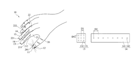
FIG. 1A is a schematic diagram of an input device for a finger touch interface according to the present disclosure;
FIG. 1B is a schematic diagram of a first magnetic field sensing unit and a second magnetic field sensing unit of the input device according to the present disclosure;
FIG. 2 is a schematic diagram of an input system for a finger touch interface according to the present disclosure; and
FIG. 3 is a schematic flow diagram showing an input method for a finger touch interface according to the present disclosure.
DETAILED DESCRIPTION OF PREFERRED EMBODIMENTS
The following illustrative embodiments are provided to illustrate the disclosure of the present disclosure, these and other advantages and effects can be apparent to those in the art after reading this specification. Various modifications and variations can be made without departing from the spirit of the present disclosure.
Referring to FIGS. 1A and 1B, an input device 10 for a finger touch interface according to the present disclosure has a magnetic unit 11, at least a first magnetic field sensing unit 13, and at least a second magnetic field sensing unit 14. The magnetic unit 11 is worn on the tip 201 of a user's thumb 20 (for example, on the thumbnail) to establish a magnetic field 12. The first magnetic field sensing unit 13 is worn on the tip of any finger except the thumb. Referring to FIG. 1A, the first magnetic field sensing unit 13 is worn on the tip 211 of the user's index finger 21 (for example, the index finger nail) and/or the tip 221 of the user's middle finger 22 (for example, the middle finger nail). Further, the first magnetic field sensing unit 13 can be worn on any one or all of the user's index finger, middle finger, ring finger and little finger.
The second magnetic field sensing unit 14 is worn on a segment of any finger except the thumb. Referring to FIG. 1A, the second magnetic field sensing unit 14 is worn on a segment 212 of the index finger 21, for example, the first segment and/or the second segment of the index finger 21. The second magnetic field sensing unit 14 can also be worn on a segment 222 of the middle finger 22. The second magnetic field sensing unit 14 is used to provide the size of the sensing area. According to the practical need, one or more second magnetic field sensing units 14 can be worn on a segment of any one or all of the user's index finger, middle finger, ring finger and little finger.
Referring to FIG. 1B, the first magnetic field sensing unit 13 has a first substrate 131 and a plurality of first sensors 132 mounted on the first substrate 131. The second magnetic field sensing unit 14 has a second substrate 141 and a plurality of second sensors 142 mounted on the second substrate 141.
In an embodiment, the first sensors 132 are arranged on the first substrate 131 in an array of 3×3 or larger and the first sensors 132 are separated from one another by a distance D1 of 4 mm. Further, the second sensors 142 are arranged on the second substrate 141 in an array of 1×8 or larger and the second sensors 142 are separated from one another by a distance D2 of 5 mm.
In an embodiment, the first sensors 132 and/or the second sensors 142 are one-dimensional or two-dimensional Hall sensors, for example, Winson WSH138 Hall sensors. Further, the magnetic unit 11 is a neodymium magnet.
The first/ second sensors 132, 142 are used to detect magnetic flux density of the magnetic field 12. When the magnetic unit 11 is moved close to the first/second magnetic field sensing unit 13, 14 and the magnetic field 12 is sensed by the first/ second sensors 132, 142, a first signal or a second signal can be generated by the first/ second sensors 132, 142 according to variation of the magnetic flux density of the magnetic field 12. The first signal indicates position of the magnetic unit 11 relative to the first/second magnetic field sensing unit 13, 14, and the second signal indicates movement of the magnetic unit 11 relative to the first/second magnetic field sensing unit 13, 14. In an embodiment, the second signal indicates the trace of movement of the magnetic unit 11 in the magnetic field 12 that is detectable by the first/ second sensors 132, 142.
In an embodiment, the magnetic flux density of the magnetic field 12 detected by the first/ second sensors 132, 142 is in a range of 0 to 200 Gauss (G).
In application, since the first sensors 132 of the first magnetic field sensing unit 13 are arranged in an array of 3×3 or larger, a small-range movement is suitable to be performed on the first magnetic field sensing unit 13. For example, the thumb with the magnetic unit 11 can perform an action of drawing a circle or writing a word on the first magnetic field sensing unit 13. Further, since the second sensors 142 of the second magnetic field sensing unit 14 are arranged in an array of 1×8 or larger, a linear movement or clicking is suitable to be performed on the second magnetic field sensing unit 14. Furthermore, a plurality of first/second magnetic field sensing units 13, 14 can be worn on both the index finger and the middle finger to expand the input area.
FIG. 2 shows an input system 30 for a finger touch interface according to the present disclosure. Referring to FIG. 2, the input system 30 includes the above-described input device 10, a computing unit 15 and a microprocessor 17.
The microprocessor 17 is coupled to the first magnetic field sensing unit 13 and the second magnetic field sensing unit 14 to receive the first/second signal. Further, the microprocessor 17 transmits the first/second signal through a network 16 (wired or wireless) to the computing unit 15 (for example, a mainframe computer or a server). The first/second signal serves as an input instruction of the computing unit 15.
In an embodiment, the computing unit 15 identifies the second signal using a Graffiti handwriting input method so as to determine which character the trace of the movement indicated by the second signal corresponds to.
In application, different button clicking configurations can be defined for the first magnetic field sensing unit 13 and the second magnetic field sensing unit 14 on different fingers. That is, different positions of the magnetic unit 11 on the first magnetic field sensing unit 13 and the second magnetic field sensing unit 14 are identified as different blocks that represent different instructions. For example, according to the habit of the user, each of the index finger and the middle finger can be divided into 5 blocks, the ring finger can be divided into 4 blocks, and the little finger can be divided into 2 blocks. Totally, there are 16 blocks, which represent 16 different input instructions.
FIG. 3 shows an input method for a finger touch interface according to the present disclosure. Referring to FIG. 3, first at step S01, a magnetic unit worn on the tip of a user's thumb establishes a magnetic field. Then, at step S02, at least a first/second magnetic field sensing unit senses position of the magnetic unit in the magnetic field to generate a first signal or senses movement of the magnetic unit in the magnetic field to generate a second signal. Therein, the first magnetic field sensing unit is worn on a tip of any finger except the thumb, and the second magnetic field sensing unit is worn on a segment of any finger except the thumb. Subsequently, at step S03, a microprocessor receives the first/second signal and transmits the first/second signal from the microprocessor to a computing unit through a network. Then, at step S04, the computing unit identifies the first/second signal as an input instruction of the computing unit.
According to the present disclosure, a user's index finger (and other fingers) can be used as an input area and the user's thumb can be used to interact with the input area so as to generate a signal as an input instruction of the computing unit. The input device, system and method for a finger touch interface according to the present disclosure are different from the conventional input methods using human gestures or voice. Further, the interaction process does not need to be seen. Instead, the position of the thumb can be determined by skin touch. Therefore, the present disclosure provides input technologies with high privacy and security.
The above-described descriptions of the detailed embodiments are only to illustrate the preferred implementation according to the present disclosure, and it is not to limit the scope of the present disclosure. Accordingly, all modifications and variations completed by those with ordinary skill in the art should fall within the scope of present disclosure defined by the appended claims.