US10085795B2 - Apparatus for performing an electrosurgical procedure - Google Patents
Apparatus for performing an electrosurgical procedure Download PDFInfo
- Publication number
- US10085795B2 US10085795B2 US14/887,529 US201514887529A US10085795B2 US 10085795 B2 US10085795 B2 US 10085795B2 US 201514887529 A US201514887529 A US 201514887529A US 10085795 B2 US10085795 B2 US 10085795B2
- Authority
- US
- United States
- Prior art keywords
- jaw members
- links
- shaft
- driving structure
- disposed
- Prior art date
- Legal status (The legal status is an assumption and is not a legal conclusion. Google has not performed a legal analysis and makes no representation as to the accuracy of the status listed.)
- Expired - Fee Related, expires
Links
Images


Classifications
-
- A—HUMAN NECESSITIES
- A61—MEDICAL OR VETERINARY SCIENCE; HYGIENE
- A61B—DIAGNOSIS; SURGERY; IDENTIFICATION
- A61B18/00—Surgical instruments, devices or methods for transferring non-mechanical forms of energy to or from the body
- A61B18/04—Surgical instruments, devices or methods for transferring non-mechanical forms of energy to or from the body by heating
- A61B18/12—Surgical instruments, devices or methods for transferring non-mechanical forms of energy to or from the body by heating by passing a current through the tissue to be heated, e.g. high-frequency current
- A61B18/14—Probes or electrodes therefor
- A61B18/1442—Probes having pivoting end effectors, e.g. forceps
- A61B18/1445—Probes having pivoting end effectors, e.g. forceps at the distal end of a shaft, e.g. forceps or scissors at the end of a rigid rod
- A61B18/1447—Probes having pivoting end effectors, e.g. forceps at the distal end of a shaft, e.g. forceps or scissors at the end of a rigid rod wherein sliding surfaces cause opening/closing of the end effectors
-
- A—HUMAN NECESSITIES
- A61—MEDICAL OR VETERINARY SCIENCE; HYGIENE
- A61B—DIAGNOSIS; SURGERY; IDENTIFICATION
- A61B17/00—Surgical instruments, devices or methods, e.g. tourniquets
- A61B17/28—Surgical forceps
- A61B17/29—Forceps for use in minimally invasive surgery
-
- A—HUMAN NECESSITIES
- A61—MEDICAL OR VETERINARY SCIENCE; HYGIENE
- A61B—DIAGNOSIS; SURGERY; IDENTIFICATION
- A61B17/00—Surgical instruments, devices or methods, e.g. tourniquets
- A61B17/28—Surgical forceps
- A61B17/29—Forceps for use in minimally invasive surgery
- A61B17/2909—Handles
-
- A—HUMAN NECESSITIES
- A61—MEDICAL OR VETERINARY SCIENCE; HYGIENE
- A61B—DIAGNOSIS; SURGERY; IDENTIFICATION
- A61B17/00—Surgical instruments, devices or methods, e.g. tourniquets
- A61B17/28—Surgical forceps
- A61B17/29—Forceps for use in minimally invasive surgery
- A61B17/2909—Handles
- A61B2017/2925—Pistol grips
-
- A—HUMAN NECESSITIES
- A61—MEDICAL OR VETERINARY SCIENCE; HYGIENE
- A61B—DIAGNOSIS; SURGERY; IDENTIFICATION
- A61B17/00—Surgical instruments, devices or methods, e.g. tourniquets
- A61B17/28—Surgical forceps
- A61B17/29—Forceps for use in minimally invasive surgery
- A61B2017/2926—Details of heads or jaws
- A61B2017/2932—Transmission of forces to jaw members
- A61B2017/2933—Transmission of forces to jaw members camming or guiding means
- A61B2017/2936—Pins in guiding slots
-
- A—HUMAN NECESSITIES
- A61—MEDICAL OR VETERINARY SCIENCE; HYGIENE
- A61B—DIAGNOSIS; SURGERY; IDENTIFICATION
- A61B17/00—Surgical instruments, devices or methods, e.g. tourniquets
- A61B17/28—Surgical forceps
- A61B17/29—Forceps for use in minimally invasive surgery
- A61B2017/2926—Details of heads or jaws
- A61B2017/2932—Transmission of forces to jaw members
- A61B2017/2939—Details of linkages or pivot points
- A61B2017/2941—Toggle linkages
-
- A—HUMAN NECESSITIES
- A61—MEDICAL OR VETERINARY SCIENCE; HYGIENE
- A61B—DIAGNOSIS; SURGERY; IDENTIFICATION
- A61B18/00—Surgical instruments, devices or methods for transferring non-mechanical forms of energy to or from the body
- A61B2018/00982—Surgical instruments, devices or methods for transferring non-mechanical forms of energy to or from the body combined with or comprising means for visual or photographic inspections inside the body, e.g. endoscopes
Definitions
- the present disclosure relates to an apparatus for performing an electrosurgical procedure. More particularly, the present disclosure relates to an electrosurgical apparatus including an end effector assembly having a pair of jaw members that provide a mechanical advantage at the end effector.
- Electrosurgical instruments e.g., electrosurgical forceps (open or closed type) are well known in the medical arts and typically include a housing, a handle assembly, a shaft and an end effector assembly attached to a distal end of the shaft.
- the end effector includes jaw members that are configured to manipulate tissue (e.g., grasp and seal tissue).
- the electrosurgical forceps utilizes both mechanical clamping action and electrical energy to effect hemostasis by heating the tissue and blood vessels to coagulate, cauterize, seal, cut, desiccate, and/or fulgurate tissue.
- one or more driving mechanisms e.g., a drive assembly including a drive element, is utilized to cooperate with one or more components operatively associated with the end effector to impart movement to one or both of the jaw members.
- one or more types of suitable devices may be operably associated with the electrosurgical forceps.
- one or more cam members e.g., a cam pin
- the drive element e.g., a drive rod, wire, cable, etc.
- the cam slots are operably disposed on proximal ends of the jaw members.
- the proximal ends of the jaw members are configured to extend outside of the shaft profile. In the extended position, the proximal ends of the jaw members are commonly referred to as “flags.”
- the shaft may bend or deform during the course of an electrosurgical procedure.
- a clinician may intentionally bend or articulate the shaft to gain desired mechanical advantage at the surgical site.
- the surgical environment may cause unintentional or unwanted bending or flexing of the shaft, such as, for example, in the instance where the shaft is a component of a catheter-based electrosurgical forceps.
- shafts associated with catheter-based electrosurgical forceps are typically designed to function with relatively small jaw members, e.g., jaw members that are configured to pass through openings that are 3 mm or less in diameter. Accordingly, the shaft and operative components associated therewith, e.g., a drive rod, are proportioned appropriately. That is, the shaft and drive rod are relatively small.
- any forces or frictional losses at the distal end of the shaft including those caused by the “flags” extending through the shaft profile and having to displace the flexible insulation may be transferred to the drive rod, drive element, and/or a spring operably associated with the drive assembly, which, in turn, may diminish, impede and/or prevent effective transfer of the desired closure force that is needed at the jaw members.
- the frictional losses may also lessen the operative life of the spring, which, in turn, ultimately lessens the operative life of the electrosurgical instrument.
- the present disclosure provides an endoscopic forceps.
- the endoscopic forceps includes a housing having a shaft that extends therefrom and defines a longitudinal axis therethrough.
- An end effector assembly is operatively connected to a distal end of the shaft and includes a pair of first and second jaw members.
- the first and second jaw members are pivotably coupled to one another.
- the first and second jaw members are movable relative to one another from an open position, wherein the first and second jaw members are disposed in spaced relation relative to one another, to a clamping position, wherein the first and second jaw members cooperate to grasp tissue therebetween.
- a drive mechanism includes a driving structure.
- a link assembly includes two or more links that are operably coupled to each other and the driving structure.
- the two or more links are operably coupled to respective ones of the first and second jaw members at proximal ends thereof.
- the proximal ends of the first and second jaw members each includes a stop member that is configured to contact the respective one of the at least two links.
- the stop members of the first and second jaw members include a generally slanted trailing edge that is configured to contact a leading edge of the respective one of the at least two links as the at least two links transition past vertical such that the first and second jaw members are releasably maintained in the clamping position.
- the present disclosure provides endoscopic forceps.
- the endoscopic forceps includes a housing having a shaft that extends therefrom and defines a longitudinal axis therethrough.
- the shaft has a cam operably disposed thereon adjacent a distal end thereof.
- An end effector assembly is operatively connected to a distal end of the shaft adjacent the cam and includes a pair of first and second jaw members pivotably coupled to one another.
- One or both of the first and second jaw members are movable relative to the other jaw member from an open or neutral position, wherein the first and second jaw members are disposed in spaced relation relative to one another, to a clamping position, wherein the first and second jaw members cooperate to grasp tissue therebetween.
- a drive mechanism includes a driving structure.
- a link assembly includes two or more links.
- a top portion of one of the links operably couples to a bottom portion of the other link.
- the top and bottom portions of the links are operably coupled to each other and the driving structure via a pivot pin.
- the two or more links are operably coupled to respective ones of the first and second jaw members at proximal ends thereof.
- FIG. 1 is a side, perspective view of an endoscopic bipolar forceps showing an end effector assembly including jaw members according to an embodiment of the present disclosure
- FIG. 2 is a side, perspective view of the endoscopic bipolar forceps depicted in FIG. 1 illustrating internal components associated with a handle assembly associated with the endoscopic bipolar forceps;
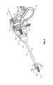
- FIG. 3 is a schematic view of the jaw members depicted in FIGS. 1 and 2 illustrating a distal end of a driving structure operably coupled to the jaw members;
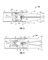
- FIG. 4 is a schematic view illustrating a distal end of the driving structure depicted in FIG. 3 according to another embodiment of the present disclosure
- FIG. 5 is a schematic view illustrating an end effector assembly including jaw members according to another embodiment of the present disclosure
- FIG. 6 is a schematic view illustrating an end effector assembly including jaw members according to yet another embodiment of the present disclosure
- FIG. 7 is a schematic view illustrating an end effector assembly including jaw members according to still another embodiment of the present disclosure.
- FIG. 8 is a schematic view illustrating an end effector assembly including jaw members according to still yet another embodiment of the present disclosure.
- FIG. 9 is a schematic view illustrating an end effector assembly including jaw members according to yet another embodiment of the present disclosure.
- FIG. 10 is a schematic view illustrating an end effector assembly including jaw members according to still yet another embodiment of the present disclosure.
- FIG. 11 is a schematic view illustrating an end effector assembly including jaw members according to yet another embodiment of the present disclosure.
- proximal as is traditional, will refer to an end which is closer to the user, while the term “distal” will refer to an end that is farther from the user.
- an illustrative embodiment of an electrosurgical apparatus e.g., a bipolar forceps 10 (forceps 10 ) is shown.
- Forceps 10 is operatively and selectively coupled to an electrosurgical generator (not shown) for performing an electrosurgical procedure.
- an electrosurgical procedure may include sealing, cutting, cauterizing coagulating, desiccating, and fulgurating tissue all of which may employ RF energy.
- the electrosurgical generator may be configured for monopolar and/or bipolar modes of operation and may include or be in operative communication with a system that may include one or more processors in operative communication with one or more control modules (not shown) that are executable on the processor.
- the control module may be configured to instruct one or more modules to transmit electrosurgical energy, which may be in the form of a wave or signal/pulse, via one or more cables (e.g., an electrosurgical cable 310 ) to the forceps 10 .
- Forceps 10 is shown configured for use with various electrosurgical procedures and generally includes a housing 20 , an electrosurgical cable 310 that connects the forceps 10 to the electrosurgical generator, a rotating assembly 80 and a trigger assembly 70 .
- a rotating assembly 80 for a more detailed description of the rotating assembly 80 , trigger assembly 70 , and electrosurgical cable 310 (including line-feed configurations and/or connections), reference is made to commonly-owned U.S. patent application Ser. No. 11/595,194 filed on Nov. 9, 2006, now U.S. Patent Publication No. 2007/0173814.
- forceps 10 includes a shaft 12 that has a distal end 14 configured to mechanically engage an end effector assembly 100 operably associated with the forceps 10 and a proximal end 16 that mechanically engages the housing 20 .
- a cam slot 13 of suitable configuration is positioned at the distal end 4 of the shaft 12 and is configured to receive a pivot pin 111 therein such that the pivot pin 111 may translate therein ( FIGS. 1-4 ).
- the cam slot 13 is defined through the shaft 12 .
- a resilient member in the form of a compression spring 15 is provided at the distal 14 end of the shaft 12 .
- the spring 15 is grounded to an internal wall of the shaft 12 and couples to the pivot pin 111 via a one or more suitable coupling methods ( FIGS. 3 and 4 ).
- a spring coupler 17 operably couples the pivot pin 111 to the spring 15 .
- Handle assembly 30 includes a fixed handle 50 and movable handle 40 ( FIGS. 1 and 2 ).
- fixed handle 50 is integrally associated with housing 20 .
- Movable handle 40 is movable relative to fixed handle 50 for effecting movement of one or more components, e.g., driving structure 133 , operably associated with a drive mechanism 130 ( FIGS. 2 and 3 ).
- Handle assembly 30 including movable handle 40 may be configured such that proximal movement of the movable handle 40 “pushes” the driving structure 133 , which, in turn, imparts movement of the jaw members 110 and 120 from a normally open position ( FIG. 1 ) to closed or clamping position ( FIGS. 2 and 3 ).
- handle assembly 30 including movable handle 40 and drive mechanism 130 may be configured such that proximal movement of the movable handle 40 “pulls” the driving structure 133 , which, in turn, imparts movement of the jaw members 110 and 120 from a normally an open position ( FIG. 1 ) to a closed position, wherein the jaw members 110 and 120 are configured to grasp tissue therebetween.
- Drive mechanism 130 is in operative communication with movable handle 40 (see FIGS. 1 and 2 ) for imparting movement of one or, in some instances, both of the jaw members 110 , 120 of end effector assembly 100 . More particularly, one or more suitable mechanical interfaces, e.g., a linkage interface, gear interface, or combination thereof operably couples the movable handle 40 to the drive mechanism 130 . In the embodiment illustrated in FIGS. 1-3 , proximal movement of the movable handle 40 moves the jaw members 110 and 120 toward each other from the normally open position to the clamping position.
- Driving structure 133 is configured such that distal movement thereof causes the jaw members 110 and 120 to move from the open position ( FIG. 1 ) to the clamping position ( FIGS. 2 and 3 ) and vice versa.
- driving structure 133 may be any suitable driving structure or mechanism including but not limited to a wire, rod, cable, band, etc.
- driving structure 133 is a substantially flexible drive rod 133 of suitable proportion that is dimensioned to translate within the shaft 12 (see FIGS. 1-3 ).
- Drive rod 133 is dimensioned such that the drive rod 133 does not to “buckle” or “kink” when the drive rod 133 is moved distally and/or proximally within the shaft 12 .
- Drive rod 133 includes a proximal end (not explicitly shown) that is in operative communication with the movable handle 40 .
- a distal end 135 of the drive rod 133 operably couples to the end effector 100 and/or jaw members 110 and 120 . More particularly, and in the embodiment illustrated in FIG. 3 , a pivot pin 21 a (or rivet, fastener, living-hinge or the like) operably couples the distal end 135 of the drive rod 133 to a link assembly 19 .
- Link assembly 19 is an over-the-center link type and includes two or more links.
- link assembly 19 includes two links 19 a and 19 b .
- Links 19 a and 19 b are pivotably coupled to each other via one or more suitable coupling methods. More particularly, pivot pin 21 a operably couples the distal end 135 of the drive rod 133 to a top portion of the link 19 a and a bottom portion of the link 19 b .
- Link assembly 19 including links 19 a and 19 b serves to latch the jaw members 110 and 120 in the closed or clamping position when the links 19 a and 19 b and/or pivot pin 21 a moves past a center point of the link assembly 19 .
- the links 19 a and 19 b are configured to contact and/or releasably engage the jaw members 110 and 120 (or component associated therewith) of the end effector such that the jaw members 110 and 120 remain in the closed or clamping position, described in greater detail below.
- having the link assembly 19 serve as a latch may eliminate the need for a separate latching device in the housing 20 and/or handle assembly 30 as is typically utilized with conventional forceps.
- the link assembly 19 provides an additional mechanical advantage when closing the jaw members 110 and 120 at the beginning of a closing or clamping stroke (i.e., when the movable handle 40 is moved proximally).
- the force at the jaw members 110 and 120 is controlled by the geometry and stiffness of the links 19 a and 19 b and/or the jaw members 110 and 120 (or operative components associated therewith).
- a top portion of the link 19 b operably couples to jaw member 120 . More particularly, a pivot pin 21 b operably couples the top portion of the link 19 b to a proximal end 127 a of the jaw member 120 ( FIG. 3 ). Likewise, a pivot pin 21 c operably couples a top portion of the link 19 a to the jaw member 110 ( FIG. 3 ).
- End effector assembly 100 is illustrated operably disposed at the distal end 14 of the shaft 12 ( FIGS. 1-3 ).
- End effector assembly 100 includes opposing jaw members 110 and 120 that mutually cooperate to grasp, seal and, in some cases, divide large tubular vessels and large vascular tissues.
- jaw members 110 and 120 are movable relative to each other.
- Jaw members 110 , 120 are operatively and pivotably coupled to each other via a pivot pin 111 and are located adjacent the distal end 14 of shaft 12 .
- Electrically conductive seal plates 118 and 128 are operably supported on and secured to respective distal ends 117 b and 127 b of jaw housings 117 and 127 .
- Jaw members 110 and 120 including respective jaw housings 117 and 127 , and operative components associated therewith, may be formed from any suitable material, including but not limited to metal, metal alloys, plastic, plastic composites, ceramics, ceramic composites, and so forth.
- Jaw housing 127 and 117 of the respective jaw members 110 and 120 are substantially identical to each other. In view thereof, the operative features of jaw housing 127 are described in detail, and only those features that are unique to jaw member 110 are described hereinafter.
- Jaw housing 127 includes distal end 127 b that is configured to operably support seal plate 128 and proximal end 127 a that operably couples to the distal end 14 of shaft 12 and to the top portion of the link 19 b .
- Proximal end 127 a includes a generally elongated configuration, and is dimensioned to move, e.g., pivot, within the shaft 12 from the open position to the closed or clamping position.
- Pivot pin 111 couples the first and second jaw members 110 and 120 , respectively ( FIG. 3 ) for pivotal movement relative to one another.
- Proximal end 127 a serves as a beam that, in concert with the links 19 a and 19 b , regulates a clamping force at the jaw members 110 and 120 when the links 19 a and 19 b transition past vertical and the jaw members 110 and 120 are in the clamping position with tissue disposed therebetween.
- Proximal end 127 a may be relatively resilient, or in some instances, may be substantially rigid. The resiliency, or lack thereof, may be varied based on a specific surgical procedure, manufacturer and/or user preference, etc. In the embodiment illustrated in FIG. 3 , proximal end 127 a is relatively resilient.
- stop member 23 b are operably disposed on the proximal end 127 a of the jaw housing 127 .
- Stop member 23 b is configured to contact and/or releasably engage the link 19 b of the link assembly 19 when the links 19 a and 19 b have transitioned past vertical.
- stop member 23 b includes an angled trailing edge 25 that is configured to contact a leading edge 27 of the link 19 b . This contact between the angled trailing edge 25 of the stop 23 b and the leading edge 27 of the link 19 b facilitates “latching” jaw member 120 in the clamping position. That is, when the angled trailing edge 25 contacts the leading edge 27 , the links 19 a and 19 b including pivot pin 21 a are prevented from moving distally.
- Jaw housing 117 of jaw member 110 includes components similar to that of the components associated with jaw housing 127 of jaw member 120 . More particularly, jaw housing 117 includes proximal end 117 a that functions similarly to that of proximal end 127 a of jaw housing 127 a . Proximal end 117 a of the jaw member 110 includes a stop member 23 a having an angled trailing edge 31 that is configured to contact a corresponding leading edge 35 of the link 19 a . Stop 23 a functions in a manner substantially similar to that of stop 23 b.
- the jaw members 110 and 120 may be coupled to each other via any suitable coupling methods.
- an opening 108 is defined in and extends through each jaw housing 117 and 127 and is configured to receive pivot pin 111 . Opening 108 is shown engaged with pivot pin 111 and as such is not explicitly visible.
- pivot pin 111 is positioned within the openings associated with each of the jaw members 110 and 120 .
- the jaw members 120 and/or jaw member 110 may be pivotably supported at the distal end 14 of the shaft 12 by known methods, such as, for example, by the method described in commonly-owned U.S. Pat. No. 7,597,693 to Garrison filed on Jun. 13, 2003.
- jaw members 110 and 120 are, initially, in the open position ( FIG. 1 ). Tissue is positioned between the jaw members 110 and 120 . Once tissue is positioned between the jaw members 110 and 120 , movable handle 40 is moved proximally ( FIG. 2 ), which, in turn, causes the drive rod 133 to move distally. Distal movement of drive rod 133 causes the links 19 a and 19 b to pivot, i.e., in respective clockwise and counterclockwise directions, about pivot pins 21 a - 21 c and move distally. As links 19 a and 19 b move distally, the pivot pin 111 moves distally against the bias of the spring 15 and the jaw members 110 and 120 move toward one another and to the clamping position.
- links 19 a and 19 b transition past vertical and the respective leading edges 35 and 27 of links 19 a and 19 b contact respective trailing edges 31 and 25 of stops 23 a and 23 b .
- Contact between the leading edges 35 and 27 and trailing edges 31 and 25 “latches” the jaw members 110 and 120 in the clamping position.
- tissue is electrosurgically treated, e.g., tissue is sealed.
- movable handle 40 is released and pivot pin 15 moves proximally and the jaw members 110 and 120 move away from one another and back to the open or neutral position.
- the unique configuration of the link assembly 19 including links 19 a and 19 b and proximal ends 117 a and 127 a improves the opening and closing angles typically associated with known forceps jaw designs. Moreover, the unique configuration of the link assembly 19 including links 19 a and 19 b and proximal ends 117 a and 127 a eliminates the need of having the proximal ends 117 a and 127 a (“flags”) extend past the profile of the shaft 12 .
- a cam member 41 may be operably coupled to the shaft 12 and operably disposed adjacent the end effector 100 .
- the stop members 23 a and 23 b are not shown in FIG. 4 .
- the cam member 41 is configured to cam the links 19 a and 19 b toward a horizontal position and each other as the drive rod 133 is moved proximally.
- the cam member 41 includes an opening 43 that is configured to receive the drive rod 133 therethrough.
- Cam member 41 includes slanted leading edges 45 and 47 that are configured to contact respective trailing edges 49 and 51 of links 19 a and 19 b such that the jaw members 110 and 120 remain in the open or neutral position.
- one or more resilient members e.g., a compression spring 200
- a compression spring 200 may be operably associated with or coupled to either the link assembly 19 including links 19 a and 19 b and/or one or both of the jaw members 110 and 120 (see FIG. 5 , for example).
- a compression spring 200 may be coupled to the pivot pin 21 a and the pivot pin 111 by one or more suitable coupling methods, e.g., soldering.
- the spring 200 may be configured to provide a clamping force or seal force in the range of about 3 kg/cm 2 to about 16 kg/cm 2 between the jaw members 110 and 120 when the jaw members 110 and 120 are in the clamping position.
- End effector assembly 300 is illustrated. End effector assembly 300 is substantially similar to end effector 100 . As a result thereof, only those features unique to end effector 300 are described herein.
- the cam member 41 is configured to translate along the longitudinal axis “A-A” (see FIG. 5 ). More particularly, cam member 41 is movable from a proximal position that corresponds to the jaw members 110 and 120 being in the clamping position to a distal position that corresponds to the jaw members being in the open position.
- the cam member 41 operably couples (via one or more suitable coupling methods, e.g., soldering) to a bifurcated distal end 135 having bifurcated ends 135 a and 135 b and the link assembly 19 is fixedly attached to an internal frame of the shaft 12 .
- Operation of the forceps 10 with the end effector 200 is substantially similar to that of end effector 100 .
- a distinguishing feature of the operation of the forceps 10 with the end effector 300 when compared to the end effector 100 is that the jaw members 100 and 200 are biased in the clamping configuration by the spring 200 that provides a clamping force or seal force in the range of about 3 kg/cm 2 to about 16 kg/cm 2 between the jaw members 110 and 120 .
- cam member 41 moves distally and contacts the links 19 a and 19 b , which, in turn, causes the links 19 a and 19 b to pivot about the pivot pin 21 a and the jaw members 110 and 120 to move away from each other to the open position against the bias of the spring 200 .
- End effector assembly 400 is illustrated.
- End effector assembly 400 is substantially similar to end effectors 100 and 300 .
- a cam member 410 includes two generally arcuate slots 46 a and 46 b that respectively couple to pivot pins 21 c and 21 b of the links 19 a and 19 b (see FIG. 6 ). Operation of the forceps 10 with the end effector 400 is substantially similar to that of end effector 300 .
- cam member 41 distal movement of the cam member 410 causes the pivot pins 21 c and 21 b to translate distally within the arcuate cam slots 46 a and 46 b , respectively, which, in turn, causes the jaw members 110 and 120 to move away from each other to the open position against the bias of the spring 200 .
- End effector assembly 500 is illustrated. End effector assembly 500 is substantially similar to end effectors 100 and 300 . As a result thereof, only those features unique to end effector 500 are described herein.
- the distal end 135 of the driving structure 133 is bifurcated or split with two legs or branches 135 a and 135 b that couple to respective resilient members 200 a and 200 b.
- Resilient members 200 a and 200 b may be any suitable type of resilient member including but not limited to: springs selected from the group consisting of coil, leaf and tension; gas or fluid pistons; and elastomers or other compliant materials.
- a proximal end of the resilient member 200 a operably couples to the branch 135 a of the driving structure 133 by any of the aforementioned coupling methods (e.g., soldering, welding, or solid joints) and a distal end of the resilient member 200 a operably couples (e.g., also by soldering) to a movable cam member 510 (cam member 510 ).
- a proximal end of the resilient member 200 b operably couples, e.g., via soldering, to the branch 135 b of the driving structure 133 and a distal end of the resilient member 200 b operably couples (e.g., also by soldering) to the pivot pin 21 a of the link assembly 19 .
- the resilient members 200 a and 200 b are disposed in different horizontal planes from each other. More particularly, resilient member 200 a is located above the resilient member 200 b.
- a cam member 510 includes two slanted or angled cam slots 510 a and 510 b that are configured to house respective stationary cam pins 511 a and 511 b that are operably coupled to the jaw members 120 and 110 , respectively.
- Cam member 510 is movable along the longitudinal axis “A-A.”
- the cam slots 510 a and 510 b may be in the jaw members 110 and 120 and the cam pins 511 a and 511 b may be attached to the cam member 510 .
- proximal movement of the movable handle 40 causes the driving structure 133 including the bifurcated distal end 135 to move distally, thus, moving the cam member 510 including the cam slots 510 a and 510 b distally, which, in turn, cams the cam pins 511 a and 511 b causing the jaw members 110 and 120 to move toward each other to the clamping position ( FIG. 7 ).
- Distal motion of movable handle 40 causes the driving structure 133 including the bifurcated distal end 135 to move proximally, thus, moving the cam member 510 including the cam slots 510 a and 510 b proximally, which, in turn, cams the cam pins 511 a and 511 b causing the jaw members 110 and 120 to move away from each other to the open position.
- End effector assembly 600 is illustrated. End effector assembly 600 is substantially similar to end effector 500 . As a result thereof, only those features unique to end effector 600 are described herein.
- the jaw members 110 and 120 illustrated in FIG. 8 include respective proximal ends 117 a and 127 a that are “offset” from the respective distal ends 117 b and 127 b.
- the cam pin 21 b operably couples the link 19 b , the cam slot 510 a and the proximal end 117 a of the jaw member 110 to each other.
- the cam pin 21 c operably couples the link 19 a , the cam slot 510 b and the proximal end 127 a of the jaw member 120 to each other.
- proximal movement of the movable handle 40 causes the driving structure 133 including the bifurcated distal end 135 to move distally, thus, moving the cam member 510 including the cam slots 510 a and 510 b distally, which, in turn, cams the cam pins 511 a and 511 b causing the jaw members 110 and 120 to move away from each other to the open position ( FIG. 8 ).
- Distal motion of movable handle 40 causes the driving structure 133 including the bifurcated distal end 135 to move proximally, thus, moving the cam member 510 including the cam slots 510 a and 510 b proximally, which, in turn, cams the cam pins 511 a and 511 b causing the jaw members 110 and 120 to toward each other to the closed position.
- End effector assembly 700 is illustrated. End effector assembly 700 is substantially similar to end effector 600 . As a result thereof, only those features unique to end effector 700 are described herein.
- the cam pin 21 b operably couples the link 19 b , the cam slot 510 a and the proximal end 127 a of the jaw member 120 to each other.
- the cam pin 21 c operably couples the link 19 a , the cam slot 510 b and the proximal end 117 a of the jaw member 110 to each other.
- the driving structure 133 does not include a bifurcated distal end 135 . Accordingly, unlike the resilient member 200 a that includes a proximal end that operably couples to the branch 135 a of the driving structure 133 , a proximal end of the resilient member 200 a ′ is operably coupled to the pivot pin 21 a ( FIG. 9 ). Moreover, the spring 200 a ′ is disposed in the same horizontal plane as the spring 200 b.
- proximal movement of the movable handle 40 causes the driving structure 133 to move distally, thus, moving the cam member 510 including the cam slots 510 a and 510 b distally, which, in turn, cams the pivot pins 21 b and 21 c causing the jaw members 110 and 120 to move toward each other to the clamping position ( FIG. 9 ).
- Distal motion of movable handle 40 causes the driving structure 133 to move proximally, thus, moving the cam member 510 including the cam slots 510 a and 510 b proximally, which, in turn, cams the pivot pins 21 b and 21 c causing the jaw members 110 and 120 to move away from each other to the open position.
- End effector assembly 800 is illustrated. End effector assembly 800 is substantially similar to end effector 700 . As a result thereof, only those features unique to end effector 800 are described herein.
- a support structure 801 of suitable proportion is operably disposed adjacent the end effector 800 .
- Support structure 801 is configured to couple to one or more resilient members 200 a′′.
- Each resilient member 200 a ′′ includes proximal ends that couple to a distal end of the cam member 510 and distal ends that operably couple to the support structure 801 .
- a third resilient member 200 b ′ includes a proximal end that operably couples to the pivot pin 21 a and a distal end that operably couples to the support structure 801 .
- proximal movement of the movable handle 40 causes the driving structure 133 to move distally, thus, moving the cam member 510 including the cam slots 510 a and 510 b distally, which, in turn, cams the pivot pins 21 b and 21 c causing the jaw members 110 and 120 to move toward each other to the clamping position ( FIG. 10 ).
- Distal motion of movable handle 40 causes the driving structure 133 to move proximally, thus, moving the cam member 510 including the cam slots 510 a and 510 b proximally, which, in turn, cams the pivot pins 21 b and 21 c causing the jaw members 110 and 120 to move away from each other to the open position.
- End effector assembly 900 is illustrated.
- End effector assembly 900 is substantially similar to end effectors 500 and 600 . As a result thereof, only those features unique to end effector 900 are described herein.
- a resilient member 200 c includes a distal end that operably couples to a cam pin 21 d that is operably coupled to a pair of cam slots 127 c and 117 c that are disposed on respective jaw members 120 and 110 at proximal ends 127 a and 117 a thereof.
- proximal movement of the movable handle 40 causes the driving structure 133 including bifurcated distal end 135 to move proximally, thus, moving the cam pin 21 d proximally within the cam slots 127 c and 117 c , which, in turn, causes the jaw members 110 and 120 to move toward each other to the clamping position ( FIG. 11 ).
- Distal motion of movable handle 40 causes the driving structure 133 including the bifurcated distal end 135 to move distally, thus, moving the cam pin 21 d distally within the including the cam slots 127 c and 117 c , which, in turn, causes the jaw members 110 and 120 to move away from each other to the open position.
Landscapes
- Health & Medical Sciences (AREA)
- Surgery (AREA)
- Life Sciences & Earth Sciences (AREA)
- Engineering & Computer Science (AREA)
- Biomedical Technology (AREA)
- Public Health (AREA)
- Nuclear Medicine, Radiotherapy & Molecular Imaging (AREA)
- Veterinary Medicine (AREA)
- General Health & Medical Sciences (AREA)
- Heart & Thoracic Surgery (AREA)
- Medical Informatics (AREA)
- Molecular Biology (AREA)
- Animal Behavior & Ethology (AREA)
- Physics & Mathematics (AREA)
- Otolaryngology (AREA)
- Plasma & Fusion (AREA)
- Ophthalmology & Optometry (AREA)
- Surgical Instruments (AREA)
Abstract
Description
Claims (11)
Priority Applications (2)
| Application Number | Priority Date | Filing Date | Title |
|---|---|---|---|
| US14/887,529 US10085795B2 (en) | 2011-05-23 | 2015-10-20 | Apparatus for performing an electrosurgical procedure |
| US16/141,204 US11020172B2 (en) | 2011-05-23 | 2018-09-25 | Apparatus for performing an electrosurgical procedure |
Applications Claiming Priority (2)
| Application Number | Priority Date | Filing Date | Title |
|---|---|---|---|
| US13/113,231 US9161807B2 (en) | 2011-05-23 | 2011-05-23 | Apparatus for performing an electrosurgical procedure |
| US14/887,529 US10085795B2 (en) | 2011-05-23 | 2015-10-20 | Apparatus for performing an electrosurgical procedure |
Related Parent Applications (1)
| Application Number | Title | Priority Date | Filing Date |
|---|---|---|---|
| US13/113,231 Division US9161807B2 (en) | 2011-05-23 | 2011-05-23 | Apparatus for performing an electrosurgical procedure |
Related Child Applications (1)
| Application Number | Title | Priority Date | Filing Date |
|---|---|---|---|
| US16/141,204 Division US11020172B2 (en) | 2011-05-23 | 2018-09-25 | Apparatus for performing an electrosurgical procedure |
Publications (2)
| Publication Number | Publication Date |
|---|---|
| US20160038227A1 US20160038227A1 (en) | 2016-02-11 |
| US10085795B2 true US10085795B2 (en) | 2018-10-02 |
Family
ID=47219725
Family Applications (3)
| Application Number | Title | Priority Date | Filing Date |
|---|---|---|---|
| US13/113,231 Expired - Fee Related US9161807B2 (en) | 2011-05-23 | 2011-05-23 | Apparatus for performing an electrosurgical procedure |
| US14/887,529 Expired - Fee Related US10085795B2 (en) | 2011-05-23 | 2015-10-20 | Apparatus for performing an electrosurgical procedure |
| US16/141,204 Active 2032-03-16 US11020172B2 (en) | 2011-05-23 | 2018-09-25 | Apparatus for performing an electrosurgical procedure |
Family Applications Before (1)
| Application Number | Title | Priority Date | Filing Date |
|---|---|---|---|
| US13/113,231 Expired - Fee Related US9161807B2 (en) | 2011-05-23 | 2011-05-23 | Apparatus for performing an electrosurgical procedure |
Family Applications After (1)
| Application Number | Title | Priority Date | Filing Date |
|---|---|---|---|
| US16/141,204 Active 2032-03-16 US11020172B2 (en) | 2011-05-23 | 2018-09-25 | Apparatus for performing an electrosurgical procedure |
Country Status (1)
| Country | Link |
|---|---|
| US (3) | US9161807B2 (en) |
Families Citing this family (471)
| Publication number | Priority date | Publication date | Assignee | Title |
|---|---|---|---|---|
| US7364577B2 (en) | 2002-02-11 | 2008-04-29 | Sherwood Services Ag | Vessel sealing system |
| ES2364666T3 (en) | 2001-04-06 | 2011-09-12 | Covidien Ag | SHUTTER AND DIVIDER OF GLASSES WITH NON-CONDUCTIVE BUMPER MEMBERS. |
| US9060770B2 (en) | 2003-05-20 | 2015-06-23 | Ethicon Endo-Surgery, Inc. | Robotically-driven surgical instrument with E-beam driver |
| US20070084897A1 (en) | 2003-05-20 | 2007-04-19 | Shelton Frederick E Iv | Articulating surgical stapling instrument incorporating a two-piece e-beam firing mechanism |
| US11896225B2 (en) | 2004-07-28 | 2024-02-13 | Cilag Gmbh International | Staple cartridge comprising a pan |
| US8215531B2 (en) | 2004-07-28 | 2012-07-10 | Ethicon Endo-Surgery, Inc. | Surgical stapling instrument having a medical substance dispenser |
| US7628791B2 (en) | 2005-08-19 | 2009-12-08 | Covidien Ag | Single action tissue sealer |
| US11246590B2 (en) | 2005-08-31 | 2022-02-15 | Cilag Gmbh International | Staple cartridge including staple drivers having different unfired heights |
| US7934630B2 (en) | 2005-08-31 | 2011-05-03 | Ethicon Endo-Surgery, Inc. | Staple cartridges for forming staples having differing formed staple heights |
| US10159482B2 (en) | 2005-08-31 | 2018-12-25 | Ethicon Llc | Fastener cartridge assembly comprising a fixed anvil and different staple heights |
| US11484312B2 (en) | 2005-08-31 | 2022-11-01 | Cilag Gmbh International | Staple cartridge comprising a staple driver arrangement |
| US9237891B2 (en) | 2005-08-31 | 2016-01-19 | Ethicon Endo-Surgery, Inc. | Robotically-controlled surgical stapling devices that produce formed staples having different lengths |
| US7669746B2 (en) | 2005-08-31 | 2010-03-02 | Ethicon Endo-Surgery, Inc. | Staple cartridges for forming staples having differing formed staple heights |
| US20070106317A1 (en) | 2005-11-09 | 2007-05-10 | Shelton Frederick E Iv | Hydraulically and electrically actuated articulation joints for surgical instruments |
| US8298232B2 (en) | 2006-01-24 | 2012-10-30 | Tyco Healthcare Group Lp | Endoscopic vessel sealer and divider for large tissue structures |
| US11224427B2 (en) | 2006-01-31 | 2022-01-18 | Cilag Gmbh International | Surgical stapling system including a console and retraction assembly |
| US11793518B2 (en) | 2006-01-31 | 2023-10-24 | Cilag Gmbh International | Powered surgical instruments with firing system lockout arrangements |
| US20110290856A1 (en) | 2006-01-31 | 2011-12-01 | Ethicon Endo-Surgery, Inc. | Robotically-controlled surgical instrument with force-feedback capabilities |
| US20110024477A1 (en) | 2009-02-06 | 2011-02-03 | Hall Steven G | Driven Surgical Stapler Improvements |
| US20120292367A1 (en) | 2006-01-31 | 2012-11-22 | Ethicon Endo-Surgery, Inc. | Robotically-controlled end effector |
| US8708213B2 (en) | 2006-01-31 | 2014-04-29 | Ethicon Endo-Surgery, Inc. | Surgical instrument having a feedback system |
| US7845537B2 (en) | 2006-01-31 | 2010-12-07 | Ethicon Endo-Surgery, Inc. | Surgical instrument having recording capabilities |
| US7753904B2 (en) | 2006-01-31 | 2010-07-13 | Ethicon Endo-Surgery, Inc. | Endoscopic surgical instrument with a handle that can articulate with respect to the shaft |
| US8820603B2 (en) | 2006-01-31 | 2014-09-02 | Ethicon Endo-Surgery, Inc. | Accessing data stored in a memory of a surgical instrument |
| US11278279B2 (en) | 2006-01-31 | 2022-03-22 | Cilag Gmbh International | Surgical instrument assembly |
| US8186555B2 (en) | 2006-01-31 | 2012-05-29 | Ethicon Endo-Surgery, Inc. | Motor-driven surgical cutting and fastening instrument with mechanical closure system |
| US8992422B2 (en) | 2006-03-23 | 2015-03-31 | Ethicon Endo-Surgery, Inc. | Robotically-controlled endoscopic accessory channel |
| US8322455B2 (en) | 2006-06-27 | 2012-12-04 | Ethicon Endo-Surgery, Inc. | Manually driven surgical cutting and fastening instrument |
| US10568652B2 (en) | 2006-09-29 | 2020-02-25 | Ethicon Llc | Surgical staples having attached drivers of different heights and stapling instruments for deploying the same |
| US8720766B2 (en) | 2006-09-29 | 2014-05-13 | Ethicon Endo-Surgery, Inc. | Surgical stapling instruments and staples |
| US11980366B2 (en) | 2006-10-03 | 2024-05-14 | Cilag Gmbh International | Surgical instrument |
| US11291441B2 (en) | 2007-01-10 | 2022-04-05 | Cilag Gmbh International | Surgical instrument with wireless communication between control unit and remote sensor |
| US8652120B2 (en) | 2007-01-10 | 2014-02-18 | Ethicon Endo-Surgery, Inc. | Surgical instrument with wireless communication between control unit and sensor transponders |
| US8684253B2 (en) | 2007-01-10 | 2014-04-01 | Ethicon Endo-Surgery, Inc. | Surgical instrument with wireless communication between a control unit of a robotic system and remote sensor |
| US11039836B2 (en) | 2007-01-11 | 2021-06-22 | Cilag Gmbh International | Staple cartridge for use with a surgical stapling instrument |
| US7434717B2 (en) | 2007-01-11 | 2008-10-14 | Ethicon Endo-Surgery, Inc. | Apparatus for closing a curved anvil of a surgical stapling device |
| US7673782B2 (en) | 2007-03-15 | 2010-03-09 | Ethicon Endo-Surgery, Inc. | Surgical stapling instrument having a releasable buttress material |
| US8931682B2 (en) | 2007-06-04 | 2015-01-13 | Ethicon Endo-Surgery, Inc. | Robotically-controlled shaft based rotary drive systems for surgical instruments |
| US11672531B2 (en) | 2007-06-04 | 2023-06-13 | Cilag Gmbh International | Rotary drive systems for surgical instruments |
| US7753245B2 (en) | 2007-06-22 | 2010-07-13 | Ethicon Endo-Surgery, Inc. | Surgical stapling instruments |
| US11849941B2 (en) | 2007-06-29 | 2023-12-26 | Cilag Gmbh International | Staple cartridge having staple cavities extending at a transverse angle relative to a longitudinal cartridge axis |
| US7866527B2 (en) | 2008-02-14 | 2011-01-11 | Ethicon Endo-Surgery, Inc. | Surgical stapling apparatus with interlockable firing system |
| US8573465B2 (en) | 2008-02-14 | 2013-11-05 | Ethicon Endo-Surgery, Inc. | Robotically-controlled surgical end effector system with rotary actuated closure systems |
| JP5410110B2 (en) | 2008-02-14 | 2014-02-05 | エシコン・エンド−サージェリィ・インコーポレイテッド | Surgical cutting / fixing instrument with RF electrode |
| US7819298B2 (en) | 2008-02-14 | 2010-10-26 | Ethicon Endo-Surgery, Inc. | Surgical stapling apparatus with control features operable with one hand |
| US8758391B2 (en) | 2008-02-14 | 2014-06-24 | Ethicon Endo-Surgery, Inc. | Interchangeable tools for surgical instruments |
| US11986183B2 (en) | 2008-02-14 | 2024-05-21 | Cilag Gmbh International | Surgical cutting and fastening instrument comprising a plurality of sensors to measure an electrical parameter |
| US9179912B2 (en) | 2008-02-14 | 2015-11-10 | Ethicon Endo-Surgery, Inc. | Robotically-controlled motorized surgical cutting and fastening instrument |
| US8636736B2 (en) | 2008-02-14 | 2014-01-28 | Ethicon Endo-Surgery, Inc. | Motorized surgical cutting and fastening instrument |
| US9770245B2 (en) | 2008-02-15 | 2017-09-26 | Ethicon Llc | Layer arrangements for surgical staple cartridges |
| US9005230B2 (en) | 2008-09-23 | 2015-04-14 | Ethicon Endo-Surgery, Inc. | Motorized surgical instrument |
| US9386983B2 (en) | 2008-09-23 | 2016-07-12 | Ethicon Endo-Surgery, Llc | Robotically-controlled motorized surgical instrument |
| US8210411B2 (en) | 2008-09-23 | 2012-07-03 | Ethicon Endo-Surgery, Inc. | Motor-driven surgical cutting instrument |
| US11648005B2 (en) | 2008-09-23 | 2023-05-16 | Cilag Gmbh International | Robotically-controlled motorized surgical instrument with an end effector |
| US8608045B2 (en) | 2008-10-10 | 2013-12-17 | Ethicon Endo-Sugery, Inc. | Powered surgical cutting and stapling apparatus with manually retractable firing system |
| US8114122B2 (en) | 2009-01-13 | 2012-02-14 | Tyco Healthcare Group Lp | Apparatus, system, and method for performing an electrosurgical procedure |
| US8517239B2 (en) | 2009-02-05 | 2013-08-27 | Ethicon Endo-Surgery, Inc. | Surgical stapling instrument comprising a magnetic element driver |
| RU2525225C2 (en) | 2009-02-06 | 2014-08-10 | Этикон Эндо-Серджери, Инк. | Improvement of drive surgical suturing instrument |
| US8187273B2 (en) | 2009-05-07 | 2012-05-29 | Tyco Healthcare Group Lp | Apparatus, system, and method for performing an electrosurgical procedure |
| US8430876B2 (en) | 2009-08-27 | 2013-04-30 | Tyco Healthcare Group Lp | Vessel sealer and divider with knife lockout |
| US8133254B2 (en) | 2009-09-18 | 2012-03-13 | Tyco Healthcare Group Lp | In vivo attachable and detachable end effector assembly and laparoscopic surgical instrument and methods therefor |
| US8112871B2 (en) | 2009-09-28 | 2012-02-14 | Tyco Healthcare Group Lp | Method for manufacturing electrosurgical seal plates |
| US8851354B2 (en) | 2009-12-24 | 2014-10-07 | Ethicon Endo-Surgery, Inc. | Surgical cutting instrument that analyzes tissue thickness |
| US8220688B2 (en) | 2009-12-24 | 2012-07-17 | Ethicon Endo-Surgery, Inc. | Motor-driven surgical cutting instrument with electric actuator directional control assembly |
| US8672939B2 (en) * | 2010-06-01 | 2014-03-18 | Covidien Lp | Surgical device for performing an electrosurgical procedure |
| US8409246B2 (en) | 2010-06-02 | 2013-04-02 | Covidien Lp | Apparatus for performing an electrosurgical procedure |
| US8783543B2 (en) | 2010-07-30 | 2014-07-22 | Ethicon Endo-Surgery, Inc. | Tissue acquisition arrangements and methods for surgical stapling devices |
| US11812965B2 (en) | 2010-09-30 | 2023-11-14 | Cilag Gmbh International | Layer of material for a surgical end effector |
| US10405854B2 (en) | 2010-09-30 | 2019-09-10 | Ethicon Llc | Surgical stapling cartridge with layer retention features |
| US9629814B2 (en) | 2010-09-30 | 2017-04-25 | Ethicon Endo-Surgery, Llc | Tissue thickness compensator configured to redistribute compressive forces |
| US9839420B2 (en) | 2010-09-30 | 2017-12-12 | Ethicon Llc | Tissue thickness compensator comprising at least one medicament |
| US11849952B2 (en) | 2010-09-30 | 2023-12-26 | Cilag Gmbh International | Staple cartridge comprising staples positioned within a compressible portion thereof |
| US10945731B2 (en) | 2010-09-30 | 2021-03-16 | Ethicon Llc | Tissue thickness compensator comprising controlled release and expansion |
| US8978954B2 (en) | 2010-09-30 | 2015-03-17 | Ethicon Endo-Surgery, Inc. | Staple cartridge comprising an adjustable distal portion |
| US11298125B2 (en) | 2010-09-30 | 2022-04-12 | Cilag Gmbh International | Tissue stapler having a thickness compensator |
| US9386988B2 (en) | 2010-09-30 | 2016-07-12 | Ethicon End-Surgery, LLC | Retainer assembly including a tissue thickness compensator |
| US8695866B2 (en) | 2010-10-01 | 2014-04-15 | Ethicon Endo-Surgery, Inc. | Surgical instrument having a power control circuit |
| RU2606493C2 (en) | 2011-04-29 | 2017-01-10 | Этикон Эндо-Серджери, Инк. | Staple cartridge, containing staples, located inside its compressible part |
| US8939972B2 (en) | 2011-05-06 | 2015-01-27 | Covidien Lp | Surgical forceps |
| US8685009B2 (en) | 2011-05-16 | 2014-04-01 | Covidien Lp | Thread-like knife for tissue cutting |
| US8852185B2 (en) | 2011-05-19 | 2014-10-07 | Covidien Lp | Apparatus for performing an electrosurgical procedure |
| US9161807B2 (en) | 2011-05-23 | 2015-10-20 | Covidien Lp | Apparatus for performing an electrosurgical procedure |
| US11207064B2 (en) | 2011-05-27 | 2021-12-28 | Cilag Gmbh International | Automated end effector component reloading system for use with a robotic system |
| US9072535B2 (en) | 2011-05-27 | 2015-07-07 | Ethicon Endo-Surgery, Inc. | Surgical stapling instruments with rotatable staple deployment arrangements |
| US9615877B2 (en) | 2011-06-17 | 2017-04-11 | Covidien Lp | Tissue sealing forceps |
| US8745840B2 (en) | 2011-07-11 | 2014-06-10 | Covidien Lp | Surgical forceps and method of manufacturing thereof |
| US9039732B2 (en) | 2011-07-11 | 2015-05-26 | Covidien Lp | Surgical forceps |
| US8852186B2 (en) | 2011-08-09 | 2014-10-07 | Covidien Lp | Microwave sensing for tissue sealing |
| US8845636B2 (en) | 2011-09-16 | 2014-09-30 | Covidien Lp | Seal plate with insulation displacement connection |
| US8864795B2 (en) | 2011-10-03 | 2014-10-21 | Covidien Lp | Surgical forceps |
| US8968309B2 (en) | 2011-11-10 | 2015-03-03 | Covidien Lp | Surgical forceps |
| US8968310B2 (en) | 2011-11-30 | 2015-03-03 | Covidien Lp | Electrosurgical instrument with a knife blade lockout mechanism |
| US9113897B2 (en) | 2012-01-23 | 2015-08-25 | Covidien Lp | Partitioned surgical instrument |
| US8968360B2 (en) | 2012-01-25 | 2015-03-03 | Covidien Lp | Surgical instrument with resilient driving member and related methods of use |
| US9044230B2 (en) | 2012-02-13 | 2015-06-02 | Ethicon Endo-Surgery, Inc. | Surgical cutting and fastening instrument with apparatus for determining cartridge and firing motion status |
| US8747434B2 (en) | 2012-02-20 | 2014-06-10 | Covidien Lp | Knife deployment mechanisms for surgical forceps |
| US8961514B2 (en) * | 2012-03-06 | 2015-02-24 | Covidien Lp | Articulating surgical apparatus |
| US9375282B2 (en) | 2012-03-26 | 2016-06-28 | Covidien Lp | Light energy sealing, cutting and sensing surgical device |
| BR112014024098B1 (en) | 2012-03-28 | 2021-05-25 | Ethicon Endo-Surgery, Inc. | staple cartridge |
| MX358135B (en) | 2012-03-28 | 2018-08-06 | Ethicon Endo Surgery Inc | Tissue thickness compensator comprising a plurality of layers. |
| JP6224070B2 (en) | 2012-03-28 | 2017-11-01 | エシコン・エンド−サージェリィ・インコーポレイテッドEthicon Endo−Surgery,Inc. | Retainer assembly including tissue thickness compensator |
| US9265569B2 (en) | 2012-03-29 | 2016-02-23 | Covidien Lp | Method of manufacturing an electrosurgical forceps |
| US8968311B2 (en) | 2012-05-01 | 2015-03-03 | Covidien Lp | Surgical instrument with stamped double-flag jaws and actuation mechanism |
| US9820765B2 (en) | 2012-05-01 | 2017-11-21 | Covidien Lp | Surgical instrument with stamped double-flange jaws |
| US9668807B2 (en) | 2012-05-01 | 2017-06-06 | Covidien Lp | Simplified spring load mechanism for delivering shaft force of a surgical instrument |
| US9039731B2 (en) | 2012-05-08 | 2015-05-26 | Covidien Lp | Surgical forceps including blade safety mechanism |
| US9375258B2 (en) | 2012-05-08 | 2016-06-28 | Covidien Lp | Surgical forceps |
| US9101358B2 (en) | 2012-06-15 | 2015-08-11 | Ethicon Endo-Surgery, Inc. | Articulatable surgical instrument comprising a firing drive |
| US20140001231A1 (en) | 2012-06-28 | 2014-01-02 | Ethicon Endo-Surgery, Inc. | Firing system lockout arrangements for surgical instruments |
| US20140001234A1 (en) | 2012-06-28 | 2014-01-02 | Ethicon Endo-Surgery, Inc. | Coupling arrangements for attaching surgical end effectors to drive systems therefor |
| US9289256B2 (en) | 2012-06-28 | 2016-03-22 | Ethicon Endo-Surgery, Llc | Surgical end effectors having angled tissue-contacting surfaces |
| US11202631B2 (en) | 2012-06-28 | 2021-12-21 | Cilag Gmbh International | Stapling assembly comprising a firing lockout |
| US20140005640A1 (en) * | 2012-06-28 | 2014-01-02 | Ethicon Endo-Surgery, Inc. | Surgical end effector jaw and electrode configurations |
| US9649111B2 (en) | 2012-06-28 | 2017-05-16 | Ethicon Endo-Surgery, Llc | Replaceable clip cartridge for a clip applier |
| CN104487005B (en) | 2012-06-28 | 2017-09-08 | 伊西康内外科公司 | Empty squeeze latching member |
| BR112014032776B1 (en) | 2012-06-28 | 2021-09-08 | Ethicon Endo-Surgery, Inc | SURGICAL INSTRUMENT SYSTEM AND SURGICAL KIT FOR USE WITH A SURGICAL INSTRUMENT SYSTEM |
| US20140005718A1 (en) | 2012-06-28 | 2014-01-02 | Ethicon Endo-Surgery, Inc. | Multi-functional powered surgical device with external dissection features |
| US9700310B2 (en) | 2013-08-23 | 2017-07-11 | Ethicon Llc | Firing member retraction devices for powered surgical instruments |
| US9265566B2 (en) | 2012-10-16 | 2016-02-23 | Covidien Lp | Surgical instrument |
| US10772674B2 (en) * | 2012-11-15 | 2020-09-15 | Covidien Lp | Deployment mechanisms for surgical instruments |
| US9375205B2 (en) * | 2012-11-15 | 2016-06-28 | Covidien Lp | Deployment mechanisms for surgical instruments |
| US9433462B2 (en) * | 2012-12-21 | 2016-09-06 | Cook Medical Technologies Llc | Tissue fusion system, apparatus and method |
| DE102013002813B4 (en) * | 2013-02-19 | 2017-11-09 | Rg Mechatronics Gmbh | Holding device with at least one jaw for a robotic surgical system |
| MX368026B (en) | 2013-03-01 | 2019-09-12 | Ethicon Endo Surgery Inc | Articulatable surgical instruments with conductive pathways for signal communication. |
| BR112015021082B1 (en) | 2013-03-01 | 2022-05-10 | Ethicon Endo-Surgery, Inc | surgical instrument |
| US20140257370A1 (en) * | 2013-03-05 | 2014-09-11 | Covidien Lp | Anvil Grasper |
| US9629629B2 (en) | 2013-03-14 | 2017-04-25 | Ethicon Endo-Surgey, LLC | Control systems for surgical instruments |
| US9351726B2 (en) | 2013-03-14 | 2016-05-31 | Ethicon Endo-Surgery, Llc | Articulation control system for articulatable surgical instruments |
| US9801626B2 (en) | 2013-04-16 | 2017-10-31 | Ethicon Llc | Modular motor driven surgical instruments with alignment features for aligning rotary drive shafts with surgical end effector shafts |
| BR112015026109B1 (en) | 2013-04-16 | 2022-02-22 | Ethicon Endo-Surgery, Inc | surgical instrument |
| US9962221B2 (en) | 2013-08-07 | 2018-05-08 | Covidien Lp | Bipolar surgical instrument |
| JP6416260B2 (en) | 2013-08-23 | 2018-10-31 | エシコン エルエルシー | Firing member retractor for a powered surgical instrument |
| USD788302S1 (en) | 2013-10-01 | 2017-05-30 | Covidien Lp | Knife for endoscopic electrosurgical forceps |
| US9962161B2 (en) | 2014-02-12 | 2018-05-08 | Ethicon Llc | Deliverable surgical instrument |
| US10004497B2 (en) | 2014-03-26 | 2018-06-26 | Ethicon Llc | Interface systems for use with surgical instruments |
| US9690362B2 (en) | 2014-03-26 | 2017-06-27 | Ethicon Llc | Surgical instrument control circuit having a safety processor |
| BR112016021943B1 (en) | 2014-03-26 | 2022-06-14 | Ethicon Endo-Surgery, Llc | SURGICAL INSTRUMENT FOR USE BY AN OPERATOR IN A SURGICAL PROCEDURE |
| CN106456176B (en) | 2014-04-16 | 2019-06-28 | 伊西康内外科有限责任公司 | Fastener cartridge including the extension with various configuration |
| US10426476B2 (en) | 2014-09-26 | 2019-10-01 | Ethicon Llc | Circular fastener cartridges for applying radially expandable fastener lines |
| US9844369B2 (en) | 2014-04-16 | 2017-12-19 | Ethicon Llc | Surgical end effectors with firing element monitoring arrangements |
| US20150297222A1 (en) | 2014-04-16 | 2015-10-22 | Ethicon Endo-Surgery, Inc. | Fastener cartridges including extensions having different configurations |
| BR112016023807B1 (en) | 2014-04-16 | 2022-07-12 | Ethicon Endo-Surgery, Llc | CARTRIDGE SET OF FASTENERS FOR USE WITH A SURGICAL INSTRUMENT |
| CN106456158B (en) | 2014-04-16 | 2019-02-05 | 伊西康内外科有限责任公司 | Fastener cartridge including non-uniform fastener |
| EP3970647A3 (en) * | 2014-05-16 | 2022-04-20 | Gyrus Acmi, Inc., D.B.A. Olympus Surgical | Endoscopic cutting forceps with jaw clamp lever latching mechanism |
| BR112017004361B1 (en) | 2014-09-05 | 2023-04-11 | Ethicon Llc | ELECTRONIC SYSTEM FOR A SURGICAL INSTRUMENT |
| US20160066913A1 (en) | 2014-09-05 | 2016-03-10 | Ethicon Endo-Surgery, Inc. | Local display of tissue parameter stabilization |
| US11311294B2 (en) | 2014-09-05 | 2022-04-26 | Cilag Gmbh International | Powered medical device including measurement of closure state of jaws |
| US10039592B2 (en) | 2014-09-17 | 2018-08-07 | Covidien Lp | Deployment mechanisms for surgical instruments |
| US10039593B2 (en) | 2014-09-17 | 2018-08-07 | Covidien Lp | Surgical instrument having a bipolar end effector assembly and a deployable monopolar assembly |
| US10080605B2 (en) | 2014-09-17 | 2018-09-25 | Covidien Lp | Deployment mechanisms for surgical instruments |
| US9918785B2 (en) | 2014-09-17 | 2018-03-20 | Covidien Lp | Deployment mechanisms for surgical instruments |
| US9987076B2 (en) | 2014-09-17 | 2018-06-05 | Covidien Lp | Multi-function surgical instruments |
| US10105142B2 (en) | 2014-09-18 | 2018-10-23 | Ethicon Llc | Surgical stapler with plurality of cutting elements |
| MX2017003960A (en) | 2014-09-26 | 2017-12-04 | Ethicon Llc | Surgical stapling buttresses and adjunct materials. |
| US11523821B2 (en) | 2014-09-26 | 2022-12-13 | Cilag Gmbh International | Method for creating a flexible staple line |
| US10076325B2 (en) | 2014-10-13 | 2018-09-18 | Ethicon Llc | Surgical stapling apparatus comprising a tissue stop |
| US9924944B2 (en) | 2014-10-16 | 2018-03-27 | Ethicon Llc | Staple cartridge comprising an adjunct material |
| JPWO2016063850A1 (en) * | 2014-10-21 | 2017-08-03 | 並木精密宝石株式会社 | Pinching device |
| US10517594B2 (en) | 2014-10-29 | 2019-12-31 | Ethicon Llc | Cartridge assemblies for surgical staplers |
| US11141153B2 (en) | 2014-10-29 | 2021-10-12 | Cilag Gmbh International | Staple cartridges comprising driver arrangements |
| US9844376B2 (en) | 2014-11-06 | 2017-12-19 | Ethicon Llc | Staple cartridge comprising a releasable adjunct material |
| US10736636B2 (en) | 2014-12-10 | 2020-08-11 | Ethicon Llc | Articulatable surgical instrument system |
| RU2703684C2 (en) | 2014-12-18 | 2019-10-21 | ЭТИКОН ЭНДО-СЕРДЖЕРИ, ЭлЭлСи | Surgical instrument with anvil which is selectively movable relative to staple cartridge around discrete fixed axis |
| US9844375B2 (en) | 2014-12-18 | 2017-12-19 | Ethicon Llc | Drive arrangements for articulatable surgical instruments |
| US10004501B2 (en) | 2014-12-18 | 2018-06-26 | Ethicon Llc | Surgical instruments with improved closure arrangements |
| US9844374B2 (en) | 2014-12-18 | 2017-12-19 | Ethicon Llc | Surgical instrument systems comprising an articulatable end effector and means for adjusting the firing stroke of a firing member |
| US9987000B2 (en) | 2014-12-18 | 2018-06-05 | Ethicon Llc | Surgical instrument assembly comprising a flexible articulation system |
| US10085748B2 (en) | 2014-12-18 | 2018-10-02 | Ethicon Llc | Locking arrangements for detachable shaft assemblies with articulatable surgical end effectors |
| US9763685B2 (en) | 2015-01-09 | 2017-09-19 | Gyrus Acmi, Inc. | Combination medical device |
| US10172612B2 (en) | 2015-01-21 | 2019-01-08 | Covidien Lp | Surgical instruments with force applier and methods of use |
| US11154301B2 (en) | 2015-02-27 | 2021-10-26 | Cilag Gmbh International | Modular stapling assembly |
| JP2020121162A (en) | 2015-03-06 | 2020-08-13 | エシコン エルエルシーEthicon LLC | Time dependent evaluation of sensor data to determine stability element, creep element and viscoelastic element of measurement |
| US9993248B2 (en) | 2015-03-06 | 2018-06-12 | Ethicon Endo-Surgery, Llc | Smart sensors with local signal processing |
| US10617412B2 (en) | 2015-03-06 | 2020-04-14 | Ethicon Llc | System for detecting the mis-insertion of a staple cartridge into a surgical stapler |
| US10687806B2 (en) | 2015-03-06 | 2020-06-23 | Ethicon Llc | Adaptive tissue compression techniques to adjust closure rates for multiple tissue types |
| US9924961B2 (en) | 2015-03-06 | 2018-03-27 | Ethicon Endo-Surgery, Llc | Interactive feedback system for powered surgical instruments |
| US10245033B2 (en) | 2015-03-06 | 2019-04-02 | Ethicon Llc | Surgical instrument comprising a lockable battery housing |
| US9901342B2 (en) | 2015-03-06 | 2018-02-27 | Ethicon Endo-Surgery, Llc | Signal and power communication system positioned on a rotatable shaft |
| US10052044B2 (en) | 2015-03-06 | 2018-08-21 | Ethicon Llc | Time dependent evaluation of sensor data to determine stability, creep, and viscoelastic elements of measures |
| US9808246B2 (en) | 2015-03-06 | 2017-11-07 | Ethicon Endo-Surgery, Llc | Method of operating a powered surgical instrument |
| US10441279B2 (en) | 2015-03-06 | 2019-10-15 | Ethicon Llc | Multiple level thresholds to modify operation of powered surgical instruments |
| US10390825B2 (en) | 2015-03-31 | 2019-08-27 | Ethicon Llc | Surgical instrument with progressive rotary drive systems |
| USD844138S1 (en) | 2015-07-17 | 2019-03-26 | Covidien Lp | Handle assembly of a multi-function surgical instrument |
| USD844139S1 (en) | 2015-07-17 | 2019-03-26 | Covidien Lp | Monopolar assembly of a multi-function surgical instrument |
| US10835249B2 (en) | 2015-08-17 | 2020-11-17 | Ethicon Llc | Implantable layers for a surgical instrument |
| WO2017031712A1 (en) | 2015-08-26 | 2017-03-02 | Covidien Lp | Electrosurgical end effector assemblies and electrosurgical forceps configured to reduce thermal spread |
| JP6778740B2 (en) * | 2015-09-15 | 2020-11-04 | クック・メディカル・テクノロジーズ・リミテッド・ライアビリティ・カンパニーCook Medical Technologies Llc | Forceps with locking mechanism |
| US10105139B2 (en) | 2015-09-23 | 2018-10-23 | Ethicon Llc | Surgical stapler having downstream current-based motor control |
| US10238386B2 (en) | 2015-09-23 | 2019-03-26 | Ethicon Llc | Surgical stapler having motor control based on an electrical parameter related to a motor current |
| US10299878B2 (en) | 2015-09-25 | 2019-05-28 | Ethicon Llc | Implantable adjunct systems for determining adjunct skew |
| US11890015B2 (en) | 2015-09-30 | 2024-02-06 | Cilag Gmbh International | Compressible adjunct with crossing spacer fibers |
| US10561420B2 (en) | 2015-09-30 | 2020-02-18 | Ethicon Llc | Tubular absorbable constructs |
| US10285699B2 (en) | 2015-09-30 | 2019-05-14 | Ethicon Llc | Compressible adjunct |
| US10980539B2 (en) | 2015-09-30 | 2021-04-20 | Ethicon Llc | Implantable adjunct comprising bonded layers |
| US10265068B2 (en) | 2015-12-30 | 2019-04-23 | Ethicon Llc | Surgical instruments with separable motors and motor control circuits |
| US10368865B2 (en) | 2015-12-30 | 2019-08-06 | Ethicon Llc | Mechanisms for compensating for drivetrain failure in powered surgical instruments |
| US10292704B2 (en) | 2015-12-30 | 2019-05-21 | Ethicon Llc | Mechanisms for compensating for battery pack failure in powered surgical instruments |
| US10426543B2 (en) | 2016-01-23 | 2019-10-01 | Covidien Lp | Knife trigger for vessel sealer |
| BR112018016098B1 (en) | 2016-02-09 | 2023-02-23 | Ethicon Llc | SURGICAL INSTRUMENT |
| US10245030B2 (en) | 2016-02-09 | 2019-04-02 | Ethicon Llc | Surgical instruments with tensioning arrangements for cable driven articulation systems |
| US11213293B2 (en) | 2016-02-09 | 2022-01-04 | Cilag Gmbh International | Articulatable surgical instruments with single articulation link arrangements |
| US10448948B2 (en) | 2016-02-12 | 2019-10-22 | Ethicon Llc | Mechanisms for compensating for drivetrain failure in powered surgical instruments |
| US11224426B2 (en) | 2016-02-12 | 2022-01-18 | Cilag Gmbh International | Mechanisms for compensating for drivetrain failure in powered surgical instruments |
| US10537381B2 (en) | 2016-02-26 | 2020-01-21 | Covidien Lp | Surgical instrument having a bipolar end effector assembly and a deployable monopolar assembly |
| US10617413B2 (en) | 2016-04-01 | 2020-04-14 | Ethicon Llc | Closure system arrangements for surgical cutting and stapling devices with separate and distinct firing shafts |
| US10335145B2 (en) | 2016-04-15 | 2019-07-02 | Ethicon Llc | Modular surgical instrument with configurable operating mode |
| US11607239B2 (en) | 2016-04-15 | 2023-03-21 | Cilag Gmbh International | Systems and methods for controlling a surgical stapling and cutting instrument |
| US10492783B2 (en) | 2016-04-15 | 2019-12-03 | Ethicon, Llc | Surgical instrument with improved stop/start control during a firing motion |
| US11179150B2 (en) | 2016-04-15 | 2021-11-23 | Cilag Gmbh International | Systems and methods for controlling a surgical stapling and cutting instrument |
| US10426467B2 (en) | 2016-04-15 | 2019-10-01 | Ethicon Llc | Surgical instrument with detection sensors |
| US10828028B2 (en) | 2016-04-15 | 2020-11-10 | Ethicon Llc | Surgical instrument with multiple program responses during a firing motion |
| US10456137B2 (en) | 2016-04-15 | 2019-10-29 | Ethicon Llc | Staple formation detection mechanisms |
| US10357247B2 (en) | 2016-04-15 | 2019-07-23 | Ethicon Llc | Surgical instrument with multiple program responses during a firing motion |
| US20170296173A1 (en) | 2016-04-18 | 2017-10-19 | Ethicon Endo-Surgery, Llc | Method for operating a surgical instrument |
| US11317917B2 (en) | 2016-04-18 | 2022-05-03 | Cilag Gmbh International | Surgical stapling system comprising a lockable firing assembly |
| US10426469B2 (en) | 2016-04-18 | 2019-10-01 | Ethicon Llc | Surgical instrument comprising a primary firing lockout and a secondary firing lockout |
| US10631887B2 (en) | 2016-08-15 | 2020-04-28 | Covidien Lp | Electrosurgical forceps for video assisted thoracoscopic surgery and other surgical procedures |
| US10959745B2 (en) * | 2016-12-20 | 2021-03-30 | Jet Med Innovations, LLC | Radiolucent grasping device |
| US11134942B2 (en) | 2016-12-21 | 2021-10-05 | Cilag Gmbh International | Surgical stapling instruments and staple-forming anvils |
| US10973516B2 (en) | 2016-12-21 | 2021-04-13 | Ethicon Llc | Surgical end effectors and adaptable firing members therefor |
| US11419606B2 (en) | 2016-12-21 | 2022-08-23 | Cilag Gmbh International | Shaft assembly comprising a clutch configured to adapt the output of a rotary firing member to two different systems |
| US20180168608A1 (en) | 2016-12-21 | 2018-06-21 | Ethicon Endo-Surgery, Llc | Surgical instrument system comprising an end effector lockout and a firing assembly lockout |
| US10779823B2 (en) | 2016-12-21 | 2020-09-22 | Ethicon Llc | Firing member pin angle |
| US20180168575A1 (en) | 2016-12-21 | 2018-06-21 | Ethicon Endo-Surgery, Llc | Surgical stapling systems |
| US10537325B2 (en) | 2016-12-21 | 2020-01-21 | Ethicon Llc | Staple forming pocket arrangement to accommodate different types of staples |
| US10980536B2 (en) | 2016-12-21 | 2021-04-20 | Ethicon Llc | No-cartridge and spent cartridge lockout arrangements for surgical staplers |
| US10588631B2 (en) | 2016-12-21 | 2020-03-17 | Ethicon Llc | Surgical instruments with positive jaw opening features |
| CN110087565A (en) | 2016-12-21 | 2019-08-02 | 爱惜康有限责任公司 | Surgical stapling system |
| US20180168633A1 (en) | 2016-12-21 | 2018-06-21 | Ethicon Endo-Surgery, Llc | Surgical stapling instruments and staple-forming anvils |
| US10888322B2 (en) | 2016-12-21 | 2021-01-12 | Ethicon Llc | Surgical instrument comprising a cutting member |
| JP7010956B2 (en) | 2016-12-21 | 2022-01-26 | エシコン エルエルシー | How to staple tissue |
| US10426471B2 (en) | 2016-12-21 | 2019-10-01 | Ethicon Llc | Surgical instrument with multiple failure response modes |
| US20180168625A1 (en) | 2016-12-21 | 2018-06-21 | Ethicon Endo-Surgery, Llc | Surgical stapling instruments with smart staple cartridges |
| US10682138B2 (en) | 2016-12-21 | 2020-06-16 | Ethicon Llc | Bilaterally asymmetric staple forming pocket pairs |
| US20180168615A1 (en) | 2016-12-21 | 2018-06-21 | Ethicon Endo-Surgery, Llc | Method of deforming staples from two different types of staple cartridges with the same surgical stapling instrument |
| US10675025B2 (en) | 2016-12-21 | 2020-06-09 | Ethicon Llc | Shaft assembly comprising separately actuatable and retractable systems |
| JP6983893B2 (en) | 2016-12-21 | 2021-12-17 | エシコン エルエルシーEthicon LLC | Lockout configuration for surgical end effectors and replaceable tool assemblies |
| US10987153B2 (en) * | 2017-01-16 | 2021-04-27 | Gyrus Acmi, Inc. | Forceps with active jaw entrapment of tissue |
| US10813695B2 (en) | 2017-01-27 | 2020-10-27 | Covidien Lp | Reflectors for optical-based vessel sealing |
| US10765442B2 (en) * | 2017-04-14 | 2020-09-08 | Ethicon Llc | Surgical devices and methods for biasing an end effector to a closed configuration |
| US11172980B2 (en) | 2017-05-12 | 2021-11-16 | Covidien Lp | Electrosurgical forceps for grasping, treating, and/or dividing tissue |
| US10973567B2 (en) | 2017-05-12 | 2021-04-13 | Covidien Lp | Electrosurgical forceps for grasping, treating, and/or dividing tissue |
| USD854684S1 (en) | 2017-06-08 | 2019-07-23 | Covidien Lp | Open vessel sealer with mechanical cutter |
| USD854149S1 (en) | 2017-06-08 | 2019-07-16 | Covidien Lp | End effector for open vessel sealer |
| USD843574S1 (en) | 2017-06-08 | 2019-03-19 | Covidien Lp | Knife for open vessel sealer |
| US11071554B2 (en) | 2017-06-20 | 2021-07-27 | Cilag Gmbh International | Closed loop feedback control of motor velocity of a surgical stapling and cutting instrument based on magnitude of velocity error measurements |
| US10881399B2 (en) | 2017-06-20 | 2021-01-05 | Ethicon Llc | Techniques for adaptive control of motor velocity of a surgical stapling and cutting instrument |
| USD879809S1 (en) | 2017-06-20 | 2020-03-31 | Ethicon Llc | Display panel with changeable graphical user interface |
| US11382638B2 (en) | 2017-06-20 | 2022-07-12 | Cilag Gmbh International | Closed loop feedback control of motor velocity of a surgical stapling and cutting instrument based on measured time over a specified displacement distance |
| US10888321B2 (en) | 2017-06-20 | 2021-01-12 | Ethicon Llc | Systems and methods for controlling velocity of a displacement member of a surgical stapling and cutting instrument |
| US10307170B2 (en) | 2017-06-20 | 2019-06-04 | Ethicon Llc | Method for closed loop control of motor velocity of a surgical stapling and cutting instrument |
| US11090046B2 (en) | 2017-06-20 | 2021-08-17 | Cilag Gmbh International | Systems and methods for controlling displacement member motion of a surgical stapling and cutting instrument |
| USD890784S1 (en) | 2017-06-20 | 2020-07-21 | Ethicon Llc | Display panel with changeable graphical user interface |
| US10881396B2 (en) | 2017-06-20 | 2021-01-05 | Ethicon Llc | Surgical instrument with variable duration trigger arrangement |
| US11653914B2 (en) | 2017-06-20 | 2023-05-23 | Cilag Gmbh International | Systems and methods for controlling motor velocity of a surgical stapling and cutting instrument according to articulation angle of end effector |
| USD879808S1 (en) | 2017-06-20 | 2020-03-31 | Ethicon Llc | Display panel with graphical user interface |
| US10980537B2 (en) | 2017-06-20 | 2021-04-20 | Ethicon Llc | Closed loop feedback control of motor velocity of a surgical stapling and cutting instrument based on measured time over a specified number of shaft rotations |
| US10624633B2 (en) | 2017-06-20 | 2020-04-21 | Ethicon Llc | Systems and methods for controlling motor velocity of a surgical stapling and cutting instrument |
| US11517325B2 (en) | 2017-06-20 | 2022-12-06 | Cilag Gmbh International | Closed loop feedback control of motor velocity of a surgical stapling and cutting instrument based on measured displacement distance traveled over a specified time interval |
| US10779820B2 (en) | 2017-06-20 | 2020-09-22 | Ethicon Llc | Systems and methods for controlling motor speed according to user input for a surgical instrument |
| US10813639B2 (en) | 2017-06-20 | 2020-10-27 | Ethicon Llc | Closed loop feedback control of motor velocity of a surgical stapling and cutting instrument based on system conditions |
| US10646220B2 (en) | 2017-06-20 | 2020-05-12 | Ethicon Llc | Systems and methods for controlling displacement member velocity for a surgical instrument |
| US11090049B2 (en) | 2017-06-27 | 2021-08-17 | Cilag Gmbh International | Staple forming pocket arrangements |
| US11324503B2 (en) | 2017-06-27 | 2022-05-10 | Cilag Gmbh International | Surgical firing member arrangements |
| US11266405B2 (en) | 2017-06-27 | 2022-03-08 | Cilag Gmbh International | Surgical anvil manufacturing methods |
| US10856869B2 (en) | 2017-06-27 | 2020-12-08 | Ethicon Llc | Surgical anvil arrangements |
| US10772629B2 (en) | 2017-06-27 | 2020-09-15 | Ethicon Llc | Surgical anvil arrangements |
| US10993716B2 (en) | 2017-06-27 | 2021-05-04 | Ethicon Llc | Surgical anvil arrangements |
| US10903685B2 (en) | 2017-06-28 | 2021-01-26 | Ethicon Llc | Surgical shaft assemblies with slip ring assemblies forming capacitive channels |
| US11259805B2 (en) | 2017-06-28 | 2022-03-01 | Cilag Gmbh International | Surgical instrument comprising firing member supports |
| US10588633B2 (en) | 2017-06-28 | 2020-03-17 | Ethicon Llc | Surgical instruments with open and closable jaws and axially movable firing member that is initially parked in close proximity to the jaws prior to firing |
| US10716614B2 (en) | 2017-06-28 | 2020-07-21 | Ethicon Llc | Surgical shaft assemblies with slip ring assemblies with increased contact pressure |
| USD869655S1 (en) | 2017-06-28 | 2019-12-10 | Ethicon Llc | Surgical fastener cartridge |
| US10765427B2 (en) | 2017-06-28 | 2020-09-08 | Ethicon Llc | Method for articulating a surgical instrument |
| US11246592B2 (en) | 2017-06-28 | 2022-02-15 | Cilag Gmbh International | Surgical instrument comprising an articulation system lockable to a frame |
| US11484310B2 (en) | 2017-06-28 | 2022-11-01 | Cilag Gmbh International | Surgical instrument comprising a shaft including a closure tube profile |
| USD906355S1 (en) | 2017-06-28 | 2020-12-29 | Ethicon Llc | Display screen or portion thereof with a graphical user interface for a surgical instrument |
| US11564686B2 (en) | 2017-06-28 | 2023-01-31 | Cilag Gmbh International | Surgical shaft assemblies with flexible interfaces |
| EP4070740A1 (en) | 2017-06-28 | 2022-10-12 | Cilag GmbH International | Surgical instrument comprising selectively actuatable rotatable couplers |
| US10932772B2 (en) | 2017-06-29 | 2021-03-02 | Ethicon Llc | Methods for closed loop velocity control for robotic surgical instrument |
| US10898183B2 (en) | 2017-06-29 | 2021-01-26 | Ethicon Llc | Robotic surgical instrument with closed loop feedback techniques for advancement of closure member during firing |
| US11007022B2 (en) | 2017-06-29 | 2021-05-18 | Ethicon Llc | Closed loop velocity control techniques based on sensed tissue parameters for robotic surgical instrument |
| US11304695B2 (en) | 2017-08-03 | 2022-04-19 | Cilag Gmbh International | Surgical system shaft interconnection |
| US11471155B2 (en) | 2017-08-03 | 2022-10-18 | Cilag Gmbh International | Surgical system bailout |
| US11944300B2 (en) | 2017-08-03 | 2024-04-02 | Cilag Gmbh International | Method for operating a surgical system bailout |
| US11974742B2 (en) | 2017-08-03 | 2024-05-07 | Cilag Gmbh International | Surgical system comprising an articulation bailout |
| US11154348B2 (en) | 2017-08-29 | 2021-10-26 | Covidien Lp | Surgical instruments and methods of assembling surgical instruments |
| USD907647S1 (en) | 2017-09-29 | 2021-01-12 | Ethicon Llc | Display screen or portion thereof with animated graphical user interface |
| US11399829B2 (en) | 2017-09-29 | 2022-08-02 | Cilag Gmbh International | Systems and methods of initiating a power shutdown mode for a surgical instrument |
| US10765429B2 (en) | 2017-09-29 | 2020-09-08 | Ethicon Llc | Systems and methods for providing alerts according to the operational state of a surgical instrument |
| USD917500S1 (en) | 2017-09-29 | 2021-04-27 | Ethicon Llc | Display screen or portion thereof with graphical user interface |
| USD907648S1 (en) | 2017-09-29 | 2021-01-12 | Ethicon Llc | Display screen or portion thereof with animated graphical user interface |
| US10743872B2 (en) | 2017-09-29 | 2020-08-18 | Ethicon Llc | System and methods for controlling a display of a surgical instrument |
| US10729501B2 (en) | 2017-09-29 | 2020-08-04 | Ethicon Llc | Systems and methods for language selection of a surgical instrument |
| US11134944B2 (en) | 2017-10-30 | 2021-10-05 | Cilag Gmbh International | Surgical stapler knife motion controls |
| US11090075B2 (en) | 2017-10-30 | 2021-08-17 | Cilag Gmbh International | Articulation features for surgical end effector |
| US10779903B2 (en) | 2017-10-31 | 2020-09-22 | Ethicon Llc | Positive shaft rotation lock activated by jaw closure |
| US10842490B2 (en) | 2017-10-31 | 2020-11-24 | Ethicon Llc | Cartridge body design with force reduction based on firing completion |
| US10863988B2 (en) | 2017-11-29 | 2020-12-15 | Intuitive Surgical Operations, Inc. | Surgical instrument with lockout mechanism |
| US10743874B2 (en) | 2017-12-15 | 2020-08-18 | Ethicon Llc | Sealed adapters for use with electromechanical surgical instruments |
| US10779825B2 (en) | 2017-12-15 | 2020-09-22 | Ethicon Llc | Adapters with end effector position sensing and control arrangements for use in connection with electromechanical surgical instruments |
| US10966718B2 (en) | 2017-12-15 | 2021-04-06 | Ethicon Llc | Dynamic clamping assemblies with improved wear characteristics for use in connection with electromechanical surgical instruments |
| US10828033B2 (en) | 2017-12-15 | 2020-11-10 | Ethicon Llc | Handheld electromechanical surgical instruments with improved motor control arrangements for positioning components of an adapter coupled thereto |
| US11006955B2 (en) | 2017-12-15 | 2021-05-18 | Ethicon Llc | End effectors with positive jaw opening features for use with adapters for electromechanical surgical instruments |
| US11071543B2 (en) | 2017-12-15 | 2021-07-27 | Cilag Gmbh International | Surgical end effectors with clamping assemblies configured to increase jaw aperture ranges |
| US10743875B2 (en) | 2017-12-15 | 2020-08-18 | Ethicon Llc | Surgical end effectors with jaw stiffener arrangements configured to permit monitoring of firing member |
| US10687813B2 (en) | 2017-12-15 | 2020-06-23 | Ethicon Llc | Adapters with firing stroke sensing arrangements for use in connection with electromechanical surgical instruments |
| US10779826B2 (en) | 2017-12-15 | 2020-09-22 | Ethicon Llc | Methods of operating surgical end effectors |
| US11197670B2 (en) | 2017-12-15 | 2021-12-14 | Cilag Gmbh International | Surgical end effectors with pivotal jaws configured to touch at their respective distal ends when fully closed |
| US11033267B2 (en) | 2017-12-15 | 2021-06-15 | Ethicon Llc | Systems and methods of controlling a clamping member firing rate of a surgical instrument |
| US10869666B2 (en) | 2017-12-15 | 2020-12-22 | Ethicon Llc | Adapters with control systems for controlling multiple motors of an electromechanical surgical instrument |
| US10716565B2 (en) | 2017-12-19 | 2020-07-21 | Ethicon Llc | Surgical instruments with dual articulation drivers |
| USD910847S1 (en) | 2017-12-19 | 2021-02-16 | Ethicon Llc | Surgical instrument assembly |
| US10729509B2 (en) | 2017-12-19 | 2020-08-04 | Ethicon Llc | Surgical instrument comprising closure and firing locking mechanism |
| US11020112B2 (en) | 2017-12-19 | 2021-06-01 | Ethicon Llc | Surgical tools configured for interchangeable use with different controller interfaces |
| US11045270B2 (en) | 2017-12-19 | 2021-06-29 | Cilag Gmbh International | Robotic attachment comprising exterior drive actuator |
| US10835330B2 (en) | 2017-12-19 | 2020-11-17 | Ethicon Llc | Method for determining the position of a rotatable jaw of a surgical instrument attachment assembly |
| US11311290B2 (en) | 2017-12-21 | 2022-04-26 | Cilag Gmbh International | Surgical instrument comprising an end effector dampener |
| US11129680B2 (en) | 2017-12-21 | 2021-09-28 | Cilag Gmbh International | Surgical instrument comprising a projector |
| US11076853B2 (en) | 2017-12-21 | 2021-08-03 | Cilag Gmbh International | Systems and methods of displaying a knife position during transection for a surgical instrument |
| US20190192151A1 (en) | 2017-12-21 | 2019-06-27 | Ethicon Llc | Surgical instrument having a display comprising image layers |
| US10932781B2 (en) * | 2018-02-06 | 2021-03-02 | Ethicon Llc | Features to align and close linear surgical stapler |
| US11517312B2 (en) | 2018-02-12 | 2022-12-06 | Intuitive Surgical Operations, Inc. | Surgical instrument with lockout mechanism |
| EP3758619B1 (en) | 2018-02-26 | 2024-04-03 | Intuitive Surgical Operations, Inc. | Surgical instrument with lockout mechanism |
| US11241275B2 (en) | 2018-03-21 | 2022-02-08 | Covidien Lp | Energy-based surgical instrument having multiple operational configurations |
| US11123132B2 (en) | 2018-04-09 | 2021-09-21 | Covidien Lp | Multi-function surgical instruments and assemblies therefor |
| US10780544B2 (en) | 2018-04-24 | 2020-09-22 | Covidien Lp | Systems and methods facilitating reprocessing of surgical instruments |
| US10828756B2 (en) | 2018-04-24 | 2020-11-10 | Covidien Lp | Disassembly methods facilitating reprocessing of multi-function surgical instruments |
| US11278285B2 (en) * | 2018-08-13 | 2022-03-22 | Cilag GbmH International | Clamping assembly for linear surgical stapler |
| US11039834B2 (en) | 2018-08-20 | 2021-06-22 | Cilag Gmbh International | Surgical stapler anvils with staple directing protrusions and tissue stability features |
| US11083458B2 (en) | 2018-08-20 | 2021-08-10 | Cilag Gmbh International | Powered surgical instruments with clutching arrangements to convert linear drive motions to rotary drive motions |
| US10842492B2 (en) | 2018-08-20 | 2020-11-24 | Ethicon Llc | Powered articulatable surgical instruments with clutching and locking arrangements for linking an articulation drive system to a firing drive system |
| US10912559B2 (en) | 2018-08-20 | 2021-02-09 | Ethicon Llc | Reinforced deformable anvil tip for surgical stapler anvil |
| US10779821B2 (en) | 2018-08-20 | 2020-09-22 | Ethicon Llc | Surgical stapler anvils with tissue stop features configured to avoid tissue pinch |
| US11324501B2 (en) | 2018-08-20 | 2022-05-10 | Cilag Gmbh International | Surgical stapling devices with improved closure members |
| US11207065B2 (en) | 2018-08-20 | 2021-12-28 | Cilag Gmbh International | Method for fabricating surgical stapler anvils |
| US11253256B2 (en) | 2018-08-20 | 2022-02-22 | Cilag Gmbh International | Articulatable motor powered surgical instruments with dedicated articulation motor arrangements |
| US10856870B2 (en) | 2018-08-20 | 2020-12-08 | Ethicon Llc | Switching arrangements for motor powered articulatable surgical instruments |
| USD914878S1 (en) | 2018-08-20 | 2021-03-30 | Ethicon Llc | Surgical instrument anvil |
| US11291440B2 (en) * | 2018-08-20 | 2022-04-05 | Cilag Gmbh International | Method for operating a powered articulatable surgical instrument |
| US11045192B2 (en) | 2018-08-20 | 2021-06-29 | Cilag Gmbh International | Fabricating techniques for surgical stapler anvils |
| US11471211B2 (en) | 2018-10-12 | 2022-10-18 | Covidien Lp | Electrosurgical forceps |
| US11376062B2 (en) | 2018-10-12 | 2022-07-05 | Covidien Lp | Electrosurgical forceps |
| US11350982B2 (en) | 2018-12-05 | 2022-06-07 | Covidien Lp | Electrosurgical forceps |
| CN113194846A (en) | 2018-12-21 | 2021-07-30 | 直观外科手术操作公司 | Surgical instrument with reinforced staple cartridge |
| US11857188B2 (en) | 2018-12-21 | 2024-01-02 | Intuitive Surgical Operations, Inc. | Articulation assemblies for surgical instruments |
| US11806015B2 (en) | 2018-12-21 | 2023-11-07 | Intuitive Surgical Operations, Inc. | Surgical instruments having mechanisms for identifying and/or deactivating stapler cartridges |
| US11523861B2 (en) | 2019-03-22 | 2022-12-13 | Covidien Lp | Methods for manufacturing a jaw assembly for an electrosurgical forceps |
| US11696761B2 (en) | 2019-03-25 | 2023-07-11 | Cilag Gmbh International | Firing drive arrangements for surgical systems |
| US11147553B2 (en) | 2019-03-25 | 2021-10-19 | Cilag Gmbh International | Firing drive arrangements for surgical systems |
| US11172929B2 (en) | 2019-03-25 | 2021-11-16 | Cilag Gmbh International | Articulation drive arrangements for surgical systems |
| US11147551B2 (en) | 2019-03-25 | 2021-10-19 | Cilag Gmbh International | Firing drive arrangements for surgical systems |
| US11944302B2 (en) | 2019-04-15 | 2024-04-02 | Intuitive Surgical Operations, Inc. | Staple cartridge for a surgical instrument |
| WO2020214397A1 (en) * | 2019-04-17 | 2020-10-22 | Intuitive Surgical Operations, Inc. | Surgical stapling instrument |
| US11432816B2 (en) | 2019-04-30 | 2022-09-06 | Cilag Gmbh International | Articulation pin for a surgical instrument |
| US11471157B2 (en) | 2019-04-30 | 2022-10-18 | Cilag Gmbh International | Articulation control mapping for a surgical instrument |
| US11253254B2 (en) | 2019-04-30 | 2022-02-22 | Cilag Gmbh International | Shaft rotation actuator on a surgical instrument |
| US11452528B2 (en) | 2019-04-30 | 2022-09-27 | Cilag Gmbh International | Articulation actuators for a surgical instrument |
| US11648009B2 (en) | 2019-04-30 | 2023-05-16 | Cilag Gmbh International | Rotatable jaw tip for a surgical instrument |
| US11903581B2 (en) | 2019-04-30 | 2024-02-20 | Cilag Gmbh International | Methods for stapling tissue using a surgical instrument |
| US11426251B2 (en) | 2019-04-30 | 2022-08-30 | Cilag Gmbh International | Articulation directional lights on a surgical instrument |
| US11896224B2 (en) | 2019-05-31 | 2024-02-13 | Intuitive Surgical Operations, Inc. | Staple cartridge for a surgical instrument |
| US11219455B2 (en) | 2019-06-28 | 2022-01-11 | Cilag Gmbh International | Surgical instrument including a lockout key |
| US11684434B2 (en) | 2019-06-28 | 2023-06-27 | Cilag Gmbh International | Surgical RFID assemblies for instrument operational setting control |
| US11771419B2 (en) | 2019-06-28 | 2023-10-03 | Cilag Gmbh International | Packaging for a replaceable component of a surgical stapling system |
| US11638587B2 (en) | 2019-06-28 | 2023-05-02 | Cilag Gmbh International | RFID identification systems for surgical instruments |
| US11399837B2 (en) | 2019-06-28 | 2022-08-02 | Cilag Gmbh International | Mechanisms for motor control adjustments of a motorized surgical instrument |
| US11627959B2 (en) | 2019-06-28 | 2023-04-18 | Cilag Gmbh International | Surgical instruments including manual and powered system lockouts |
| US11224497B2 (en) | 2019-06-28 | 2022-01-18 | Cilag Gmbh International | Surgical systems with multiple RFID tags |
| US11497492B2 (en) | 2019-06-28 | 2022-11-15 | Cilag Gmbh International | Surgical instrument including an articulation lock |
| US11464601B2 (en) | 2019-06-28 | 2022-10-11 | Cilag Gmbh International | Surgical instrument comprising an RFID system for tracking a movable component |
| US11246678B2 (en) | 2019-06-28 | 2022-02-15 | Cilag Gmbh International | Surgical stapling system having a frangible RFID tag |
| US11051807B2 (en) | 2019-06-28 | 2021-07-06 | Cilag Gmbh International | Packaging assembly including a particulate trap |
| US11350938B2 (en) | 2019-06-28 | 2022-06-07 | Cilag Gmbh International | Surgical instrument comprising an aligned rfid sensor |
| US11298132B2 (en) | 2019-06-28 | 2022-04-12 | Cilag GmbH Inlernational | Staple cartridge including a honeycomb extension |
| US11660163B2 (en) | 2019-06-28 | 2023-05-30 | Cilag Gmbh International | Surgical system with RFID tags for updating motor assembly parameters |
| US11553971B2 (en) | 2019-06-28 | 2023-01-17 | Cilag Gmbh International | Surgical RFID assemblies for display and communication |
| US11426167B2 (en) | 2019-06-28 | 2022-08-30 | Cilag Gmbh International | Mechanisms for proper anvil attachment surgical stapling head assembly |
| US11478241B2 (en) | 2019-06-28 | 2022-10-25 | Cilag Gmbh International | Staple cartridge including projections |
| US11259803B2 (en) | 2019-06-28 | 2022-03-01 | Cilag Gmbh International | Surgical stapling system having an information encryption protocol |
| US11298127B2 (en) | 2019-06-28 | 2022-04-12 | Cilag GmbH Interational | Surgical stapling system having a lockout mechanism for an incompatible cartridge |
| US11523822B2 (en) | 2019-06-28 | 2022-12-13 | Cilag Gmbh International | Battery pack including a circuit interrupter |
| US11291451B2 (en) | 2019-06-28 | 2022-04-05 | Cilag Gmbh International | Surgical instrument with battery compatibility verification functionality |
| US11376098B2 (en) | 2019-06-28 | 2022-07-05 | Cilag Gmbh International | Surgical instrument system comprising an RFID system |
| US11786325B2 (en) | 2019-07-02 | 2023-10-17 | Intuitive Surgical Operations, Inc. | Remotely controlling a system using video |
| US11576672B2 (en) | 2019-12-19 | 2023-02-14 | Cilag Gmbh International | Surgical instrument comprising a closure system including a closure member and an opening member driven by a drive screw |
| US11911032B2 (en) | 2019-12-19 | 2024-02-27 | Cilag Gmbh International | Staple cartridge comprising a seating cam |
| US11701111B2 (en) | 2019-12-19 | 2023-07-18 | Cilag Gmbh International | Method for operating a surgical stapling instrument |
| US11931033B2 (en) | 2019-12-19 | 2024-03-19 | Cilag Gmbh International | Staple cartridge comprising a latch lockout |
| US11559304B2 (en) | 2019-12-19 | 2023-01-24 | Cilag Gmbh International | Surgical instrument comprising a rapid closure mechanism |
| US11304696B2 (en) | 2019-12-19 | 2022-04-19 | Cilag Gmbh International | Surgical instrument comprising a powered articulation system |
| US11844520B2 (en) | 2019-12-19 | 2023-12-19 | Cilag Gmbh International | Staple cartridge comprising driver retention members |
| US11464512B2 (en) | 2019-12-19 | 2022-10-11 | Cilag Gmbh International | Staple cartridge comprising a curved deck surface |
| US11529139B2 (en) | 2019-12-19 | 2022-12-20 | Cilag Gmbh International | Motor driven surgical instrument |
| US11291447B2 (en) | 2019-12-19 | 2022-04-05 | Cilag Gmbh International | Stapling instrument comprising independent jaw closing and staple firing systems |
| US11234698B2 (en) | 2019-12-19 | 2022-02-01 | Cilag Gmbh International | Stapling system comprising a clamp lockout and a firing lockout |
| US11446029B2 (en) | 2019-12-19 | 2022-09-20 | Cilag Gmbh International | Staple cartridge comprising projections extending from a curved deck surface |
| US11504122B2 (en) | 2019-12-19 | 2022-11-22 | Cilag Gmbh International | Surgical instrument comprising a nested firing member |
| US11529137B2 (en) | 2019-12-19 | 2022-12-20 | Cilag Gmbh International | Staple cartridge comprising driver retention members |
| US11607219B2 (en) | 2019-12-19 | 2023-03-21 | Cilag Gmbh International | Staple cartridge comprising a detachable tissue cutting knife |
| US11642129B2 (en) | 2020-01-15 | 2023-05-09 | Intuitive Surgical Operations, Inc. | Staple cartridge and drive member for surgical instrument |
| US11622804B2 (en) | 2020-03-16 | 2023-04-11 | Covidien Lp | Forceps with linear trigger mechanism |
| USD974560S1 (en) | 2020-06-02 | 2023-01-03 | Cilag Gmbh International | Staple cartridge |
| USD975850S1 (en) | 2020-06-02 | 2023-01-17 | Cilag Gmbh International | Staple cartridge |
| USD967421S1 (en) | 2020-06-02 | 2022-10-18 | Cilag Gmbh International | Staple cartridge |
| USD976401S1 (en) | 2020-06-02 | 2023-01-24 | Cilag Gmbh International | Staple cartridge |
| USD966512S1 (en) | 2020-06-02 | 2022-10-11 | Cilag Gmbh International | Staple cartridge |
| USD975851S1 (en) | 2020-06-02 | 2023-01-17 | Cilag Gmbh International | Staple cartridge |
| USD975278S1 (en) | 2020-06-02 | 2023-01-10 | Cilag Gmbh International | Staple cartridge |
| US20220031346A1 (en) | 2020-07-28 | 2022-02-03 | Cilag Gmbh International | Articulatable surgical instruments with articulation joints comprising flexible exoskeleton arrangements |
| US11660109B2 (en) | 2020-09-08 | 2023-05-30 | Covidien Lp | Cutting elements for surgical instruments such as for use in robotic surgical systems |
| US11925406B2 (en) | 2020-09-14 | 2024-03-12 | Covidien Lp | End effector assemblies for surgical instruments |
| US11517390B2 (en) | 2020-10-29 | 2022-12-06 | Cilag Gmbh International | Surgical instrument comprising a limited travel switch |
| US11717289B2 (en) | 2020-10-29 | 2023-08-08 | Cilag Gmbh International | Surgical instrument comprising an indicator which indicates that an articulation drive is actuatable |
| US11617577B2 (en) | 2020-10-29 | 2023-04-04 | Cilag Gmbh International | Surgical instrument comprising a sensor configured to sense whether an articulation drive of the surgical instrument is actuatable |
| US11452526B2 (en) | 2020-10-29 | 2022-09-27 | Cilag Gmbh International | Surgical instrument comprising a staged voltage regulation start-up system |
| US11896217B2 (en) | 2020-10-29 | 2024-02-13 | Cilag Gmbh International | Surgical instrument comprising an articulation lock |
| US11931025B2 (en) | 2020-10-29 | 2024-03-19 | Cilag Gmbh International | Surgical instrument comprising a releasable closure drive lock |
| US11779330B2 (en) | 2020-10-29 | 2023-10-10 | Cilag Gmbh International | Surgical instrument comprising a jaw alignment system |
| US11534259B2 (en) | 2020-10-29 | 2022-12-27 | Cilag Gmbh International | Surgical instrument comprising an articulation indicator |
| US11844518B2 (en) | 2020-10-29 | 2023-12-19 | Cilag Gmbh International | Method for operating a surgical instrument |
| USD1013170S1 (en) | 2020-10-29 | 2024-01-30 | Cilag Gmbh International | Surgical instrument assembly |
| USD980425S1 (en) | 2020-10-29 | 2023-03-07 | Cilag Gmbh International | Surgical instrument assembly |
| US11849943B2 (en) | 2020-12-02 | 2023-12-26 | Cilag Gmbh International | Surgical instrument with cartridge release mechanisms |
| US11653915B2 (en) | 2020-12-02 | 2023-05-23 | Cilag Gmbh International | Surgical instruments with sled location detection and adjustment features |
| US11744581B2 (en) | 2020-12-02 | 2023-09-05 | Cilag Gmbh International | Powered surgical instruments with multi-phase tissue treatment |
| US11890010B2 (en) | 2020-12-02 | 2024-02-06 | Cllag GmbH International | Dual-sided reinforced reload for surgical instruments |
| US11678882B2 (en) | 2020-12-02 | 2023-06-20 | Cilag Gmbh International | Surgical instruments with interactive features to remedy incidental sled movements |
| US11627960B2 (en) | 2020-12-02 | 2023-04-18 | Cilag Gmbh International | Powered surgical instruments with smart reload with separately attachable exteriorly mounted wiring connections |
| US11737751B2 (en) | 2020-12-02 | 2023-08-29 | Cilag Gmbh International | Devices and methods of managing energy dissipated within sterile barriers of surgical instrument housings |
| US11653920B2 (en) | 2020-12-02 | 2023-05-23 | Cilag Gmbh International | Powered surgical instruments with communication interfaces through sterile barrier |
| US11944296B2 (en) | 2020-12-02 | 2024-04-02 | Cilag Gmbh International | Powered surgical instruments with external connectors |
| US11749877B2 (en) | 2021-02-26 | 2023-09-05 | Cilag Gmbh International | Stapling instrument comprising a signal antenna |
| US11793514B2 (en) | 2021-02-26 | 2023-10-24 | Cilag Gmbh International | Staple cartridge comprising sensor array which may be embedded in cartridge body |
| US11950777B2 (en) | 2021-02-26 | 2024-04-09 | Cilag Gmbh International | Staple cartridge comprising an information access control system |
| US11812964B2 (en) | 2021-02-26 | 2023-11-14 | Cilag Gmbh International | Staple cartridge comprising a power management circuit |
| US11744583B2 (en) | 2021-02-26 | 2023-09-05 | Cilag Gmbh International | Distal communication array to tune frequency of RF systems |
| US11730473B2 (en) | 2021-02-26 | 2023-08-22 | Cilag Gmbh International | Monitoring of manufacturing life-cycle |
| US11723657B2 (en) | 2021-02-26 | 2023-08-15 | Cilag Gmbh International | Adjustable communication based on available bandwidth and power capacity |
| US11696757B2 (en) | 2021-02-26 | 2023-07-11 | Cilag Gmbh International | Monitoring of internal systems to detect and track cartridge motion status |
| US11701113B2 (en) | 2021-02-26 | 2023-07-18 | Cilag Gmbh International | Stapling instrument comprising a separate power antenna and a data transfer antenna |
| US11950779B2 (en) | 2021-02-26 | 2024-04-09 | Cilag Gmbh International | Method of powering and communicating with a staple cartridge |
| US11980362B2 (en) | 2021-02-26 | 2024-05-14 | Cilag Gmbh International | Surgical instrument system comprising a power transfer coil |
| US11751869B2 (en) | 2021-02-26 | 2023-09-12 | Cilag Gmbh International | Monitoring of multiple sensors over time to detect moving characteristics of tissue |
| US11925349B2 (en) | 2021-02-26 | 2024-03-12 | Cilag Gmbh International | Adjustment to transfer parameters to improve available power |
| US11717291B2 (en) | 2021-03-22 | 2023-08-08 | Cilag Gmbh International | Staple cartridge comprising staples configured to apply different tissue compression |
| US11806011B2 (en) | 2021-03-22 | 2023-11-07 | Cilag Gmbh International | Stapling instrument comprising tissue compression systems |
| US11723658B2 (en) | 2021-03-22 | 2023-08-15 | Cilag Gmbh International | Staple cartridge comprising a firing lockout |
| US11826042B2 (en) | 2021-03-22 | 2023-11-28 | Cilag Gmbh International | Surgical instrument comprising a firing drive including a selectable leverage mechanism |
| US11759202B2 (en) | 2021-03-22 | 2023-09-19 | Cilag Gmbh International | Staple cartridge comprising an implantable layer |
| US11826012B2 (en) | 2021-03-22 | 2023-11-28 | Cilag Gmbh International | Stapling instrument comprising a pulsed motor-driven firing rack |
| US11737749B2 (en) | 2021-03-22 | 2023-08-29 | Cilag Gmbh International | Surgical stapling instrument comprising a retraction system |
| US11896219B2 (en) | 2021-03-24 | 2024-02-13 | Cilag Gmbh International | Mating features between drivers and underside of a cartridge deck |
| US11896218B2 (en) | 2021-03-24 | 2024-02-13 | Cilag Gmbh International | Method of using a powered stapling device |
| US11832816B2 (en) | 2021-03-24 | 2023-12-05 | Cilag Gmbh International | Surgical stapling assembly comprising nonplanar staples and planar staples |
| US11786243B2 (en) | 2021-03-24 | 2023-10-17 | Cilag Gmbh International | Firing members having flexible portions for adapting to a load during a surgical firing stroke |
| US11786239B2 (en) | 2021-03-24 | 2023-10-17 | Cilag Gmbh International | Surgical instrument articulation joint arrangements comprising multiple moving linkage features |
| US11849944B2 (en) | 2021-03-24 | 2023-12-26 | Cilag Gmbh International | Drivers for fastener cartridge assemblies having rotary drive screws |
| US11944336B2 (en) | 2021-03-24 | 2024-04-02 | Cilag Gmbh International | Joint arrangements for multi-planar alignment and support of operational drive shafts in articulatable surgical instruments |
| US11744603B2 (en) | 2021-03-24 | 2023-09-05 | Cilag Gmbh International | Multi-axis pivot joints for surgical instruments and methods for manufacturing same |
| US11857183B2 (en) | 2021-03-24 | 2024-01-02 | Cilag Gmbh International | Stapling assembly components having metal substrates and plastic bodies |
| US11849945B2 (en) | 2021-03-24 | 2023-12-26 | Cilag Gmbh International | Rotary-driven surgical stapling assembly comprising eccentrically driven firing member |
| US11903582B2 (en) | 2021-03-24 | 2024-02-20 | Cilag Gmbh International | Leveraging surfaces for cartridge installation |
| US11793516B2 (en) | 2021-03-24 | 2023-10-24 | Cilag Gmbh International | Surgical staple cartridge comprising longitudinal support beam |
| US11918217B2 (en) | 2021-05-28 | 2024-03-05 | Cilag Gmbh International | Stapling instrument comprising a staple cartridge insertion stop |
| US11974829B2 (en) | 2021-06-30 | 2024-05-07 | Cilag Gmbh International | Link-driven articulation device for a surgical device |
| US11931026B2 (en) | 2021-06-30 | 2024-03-19 | Cilag Gmbh International | Staple cartridge replacement |
| US11957337B2 (en) | 2021-10-18 | 2024-04-16 | Cilag Gmbh International | Surgical stapling assembly with offset ramped drive surfaces |
| US11877745B2 (en) | 2021-10-18 | 2024-01-23 | Cilag Gmbh International | Surgical stapling assembly having longitudinally-repeating staple leg clusters |
| US11980363B2 (en) | 2021-10-18 | 2024-05-14 | Cilag Gmbh International | Row-to-row staple array variations |
| US11937816B2 (en) | 2021-10-28 | 2024-03-26 | Cilag Gmbh International | Electrical lead arrangements for surgical instruments |
Citations (166)
| Publication number | Priority date | Publication date | Assignee | Title |
|---|---|---|---|---|
| SU401367A1 (en) | 1971-10-05 | 1973-10-12 | Тернопольский государственный медицинский институт | BIAKTIVNYE ELECTRO SURGICAL INSTRUMENT |
| DE2415263A1 (en) | 1974-03-29 | 1975-10-02 | Aesculap Werke Ag | Surgical H.F. coagulation probe has electrode tongs - with exposed ends of insulated conductors forming tong-jaws |
| DE2514501A1 (en) | 1975-04-03 | 1976-10-21 | Karl Storz | Bipolar coagulation instrument for endoscopes - has two high frequency electrodes looped over central insulating piece |
| DE2627679A1 (en) | 1975-06-26 | 1977-01-13 | Marcel Lamidey | HEMATISTIC HIGH FREQUENCY EXTRACTOR FORCEPS |
| USD249549S (en) | 1976-10-22 | 1978-09-19 | Aspen Laboratories, Inc. | Electrosurgical handle |
| USD263020S (en) | 1980-01-22 | 1982-02-16 | Rau Iii David M | Retractable knife |
| JPS61501068A (en) | 1984-01-30 | 1986-05-29 | ハルコフスキイ ナウチノ−イススレドワテルスキイ インスチチユ−ト オブスチエイ イ ネオトロジノイ ヒルルギイ | bipolar electrosurgical instrument |
| DE3423356C2 (en) | 1984-06-25 | 1986-06-26 | Berchtold Medizin-Elektronik GmbH & Co, 7200 Tuttlingen | Electrosurgical high frequency cutting instrument |
| DE3612646A1 (en) | 1985-04-16 | 1987-04-30 | Ellman International | Electrosurgical handle piece for blades, needles and forceps |
| DE8712328U1 (en) | 1987-09-11 | 1988-02-18 | Jakoubek, Franz, 7201 Emmingen-Liptingen, De | |
| USD295894S (en) | 1985-09-26 | 1988-05-24 | Acme United Corporation | Disposable surgical scissors |
| USD295893S (en) | 1985-09-25 | 1988-05-24 | Acme United Corporation | Disposable surgical clamp |
| USD298353S (en) | 1986-05-06 | 1988-11-01 | Vitalmetrics, Inc. | Handle for surgical instrument |
| USD299413S (en) | 1985-07-17 | 1989-01-17 | The Stanley Works | Folding pocket saw handle |
| JPH055106A (en) | 1990-07-31 | 1993-01-14 | Matsushita Electric Works Ltd | Production of alloy sintered body |
| JPH0540112A (en) | 1991-02-08 | 1993-02-19 | Tokico Ltd | Analyzing apparatus of component of sample liquid |
| USD343453S (en) | 1993-05-05 | 1994-01-18 | Laparomed Corporation | Handle for laparoscopic surgical instrument |
| JPH06502328A (en) | 1990-10-17 | 1994-03-17 | ボストン サイエンティフィック コーポレイション | Surgical instruments and methods |
| JPH06121797A (en) | 1992-02-27 | 1994-05-06 | United States Surgical Corp | Equipment and method for performing intracutaneous stapling of body tissue |
| US5312417A (en) | 1992-07-29 | 1994-05-17 | Wilk Peter J | Laparoscopic cannula assembly and associated method |
| USD348930S (en) | 1991-10-11 | 1994-07-19 | Ethicon, Inc. | Endoscopic stapler |
| USD349341S (en) | 1992-10-28 | 1994-08-02 | Microsurge, Inc. | Endoscopic grasper |
| JPH06285078A (en) | 1993-04-05 | 1994-10-11 | Olympus Optical Co Ltd | Forceps |
| JPH06343644A (en) | 1993-05-04 | 1994-12-20 | Gyrus Medical Ltd | Surgical peritoneoscope equipment |
| JPH06511401A (en) | 1991-06-07 | 1994-12-22 | バイタル メディカル プロダクツ コーポレイション | Bipolar electrosurgical endoscopic instrument and its method of use |
| USD354564S (en) | 1993-06-25 | 1995-01-17 | Richard-Allan Medical Industries, Inc. | Surgical clip applier |
| DE4303882C2 (en) | 1993-02-10 | 1995-02-09 | Kernforschungsz Karlsruhe | Combination instrument for separation and coagulation for minimally invasive surgery |
| US5391156A (en) | 1992-06-30 | 1995-02-21 | Ethicon, Inc. | Flexible encoscopic surgical port |
| US5396900A (en) * | 1991-04-04 | 1995-03-14 | Symbiosis Corporation | Endoscopic end effectors constructed from a combination of conductive and non-conductive materials and useful for selective endoscopic cautery |
| USD358887S (en) | 1993-12-02 | 1995-05-30 | Cobot Medical Corporation | Combined cutting and coagulating forceps |
| DE4403252A1 (en) | 1994-02-03 | 1995-08-10 | Michael Hauser | Instrument shaft for min. invasive surgery |
| JPH07265328A (en) | 1993-11-01 | 1995-10-17 | Gyrus Medical Ltd | Electrode assembly for electric surgery device and electric surgery device using it |
| JPH0856955A (en) | 1994-06-29 | 1996-03-05 | Gyrus Medical Ltd | Electric surgical apparatus |
| DE19515914C1 (en) | 1995-05-02 | 1996-07-25 | Aesculap Ag | Tong or scissor-shaped surgical instrument |
| DE19506363A1 (en) | 1995-02-24 | 1996-08-29 | Frost Lore Geb Haupt | Non-invasive thermometry in organs under hyperthermia and coagulation conditions |
| JPH08252263A (en) | 1994-12-21 | 1996-10-01 | Gyrus Medical Ltd | Electronic surgical incision apparatus and electronic surgical incision device using said apparatus |
| DE29616210U1 (en) | 1996-09-18 | 1996-11-14 | Winter & Ibe Olympus | Handle for surgical instruments |
| US5578052A (en) | 1992-10-27 | 1996-11-26 | Koros; Tibor | Insulated laparoscopic grasper with removable shaft |
| JPH08317934A (en) | 1995-04-12 | 1996-12-03 | Ethicon Endo Surgery Inc | Hemostatic device for electric surgery with adaptable electrode |
| JPH0910223A (en) | 1995-06-23 | 1997-01-14 | Gyrus Medical Ltd | Generator and system for electric operation |
| DE19608716C1 (en) | 1996-03-06 | 1997-04-17 | Aesculap Ag | Bipolar surgical holding instrument |
| JPH09122138A (en) | 1995-10-20 | 1997-05-13 | Ethicon Endo Surgery Inc | Apparatus for operation |
| USD384413S (en) | 1994-10-07 | 1997-09-30 | United States Surgical Corporation | Endoscopic suturing instrument |
| JPH1024051A (en) | 1995-09-20 | 1998-01-27 | Olympus Optical Co Ltd | Coagulation forceps with separating function |
| DE19751106A1 (en) | 1996-11-27 | 1998-05-28 | Eastman Kodak Co | Laser printer with array of laser diodes |
| JPH10155798A (en) | 1996-12-04 | 1998-06-16 | Asahi Optical Co Ltd | Hot biopsy clamp for endoscope |
| USH1745H (en) | 1995-09-29 | 1998-08-04 | Paraschac; Joseph F. | Electrosurgical clamping device with insulation limited bipolar electrode |
| USD402028S (en) | 1997-10-10 | 1998-12-01 | Invasatec, Inc. | Hand controller for medical system |
| JPH1147150A (en) | 1997-08-06 | 1999-02-23 | Olympus Optical Co Ltd | Endoscopic surgery appliance |
| JPH1170124A (en) | 1997-05-14 | 1999-03-16 | Ethicon Endo Surgery Inc | Improved electrosurgical hemostatic apparatus having anvil |
| USD408018S (en) | 1996-03-12 | 1999-04-13 | Mcnaughton Patrick J | Switch guard |
| US5904703A (en) | 1996-05-08 | 1999-05-18 | Bard Connaught | Occluder device formed from an open cell foam material |
| DE19751108A1 (en) | 1997-11-18 | 1999-05-20 | Beger Frank Michael Dipl Desig | Electrosurgical operation tool, especially for diathermy |
| US5906577A (en) | 1997-04-30 | 1999-05-25 | University Of Massachusetts | Device, surgical access port, and method of retracting an incision into an opening and providing a channel through the incision |
| JPH11169381A (en) | 1997-12-15 | 1999-06-29 | Olympus Optical Co Ltd | High frequency treating device |
| JPH11192238A (en) | 1997-10-10 | 1999-07-21 | Ethicon Endo Surgery Inc | Ultrasonic forceps coagulation device improved of pivot-attaching of forceps arm |
| JPH11244298A (en) | 1997-12-19 | 1999-09-14 | Gyrus Medical Ltd | Electric surgical instrument |
| USD416089S (en) | 1996-04-08 | 1999-11-02 | Richard-Allan Medical Industries, Inc. | Endoscopic linear stapling and dividing surgical instrument |
| JP2000102545A (en) | 1997-06-18 | 2000-04-11 | Eggers & Associates Inc | Electric tweezers for surgery |
| US6048309A (en) | 1996-03-04 | 2000-04-11 | Heartport, Inc. | Soft tissue retractor and delivery device therefor |
| USD424694S (en) | 1998-10-23 | 2000-05-09 | Sherwood Services Ag | Forceps |
| USD425201S (en) | 1998-10-23 | 2000-05-16 | Sherwood Services Ag | Disposable electrode assembly |
| WO2000036986A1 (en) | 1998-12-18 | 2000-06-29 | Karl Storz Gmbh & Co. Kg | Bipolar medical instrument |
| US6102909A (en) | 1997-08-26 | 2000-08-15 | Ethicon, Inc. | Scissorlike electrosurgical cutting instrument |
| USH1904H (en) | 1997-05-14 | 2000-10-03 | Ethicon Endo-Surgery, Inc. | Electrosurgical hemostatic method and device |
| JP2000342599A (en) | 1999-05-21 | 2000-12-12 | Gyrus Medical Ltd | Generator for electrosurgical operation, electrosurgical operation system, method for operating this system and method for performing amputation and resection of tissue by electrosurgical operation |
| JP2000350732A (en) | 1999-05-21 | 2000-12-19 | Gyrus Medical Ltd | Electrosurgical system, generator for electrosurgery, and method for cutting or excising tissue by electrosurgery |
| JP2001008944A (en) | 1999-05-28 | 2001-01-16 | Gyrus Medical Ltd | Electric surgical signal generator and electric surgical system |
| JP2001029356A (en) | 1999-06-11 | 2001-02-06 | Gyrus Medical Ltd | Electric and surgical signal generator |
| WO2001015614A1 (en) | 1999-08-27 | 2001-03-08 | Karl Storz Gmbh & Co. Kg | Bipolar medical instrument |
| JP2001128990A (en) | 1999-05-28 | 2001-05-15 | Gyrus Medical Ltd | Electro surgical instrument and electrosurgical tool converter |
| JP2001190564A (en) | 2000-01-12 | 2001-07-17 | Olympus Optical Co Ltd | Medical treatment instrument |
| WO2001054604A1 (en) | 2000-01-25 | 2001-08-02 | Aesculap Ag & Co. Kg | Bipolar gripping device |
| USD449886S1 (en) | 1998-10-23 | 2001-10-30 | Sherwood Services Ag | Forceps with disposable electrode |
| EP1159926A2 (en) | 2000-06-03 | 2001-12-05 | Aesculap Ag | Scissor- or forceps-like surgical instrument |
| USD453923S1 (en) | 2000-11-16 | 2002-02-26 | Carling Technologies, Inc. | Electrical rocker switch guard |
| USD454951S1 (en) | 2001-02-27 | 2002-03-26 | Visionary Biomedical, Inc. | Steerable catheter |
| USD457958S1 (en) | 2001-04-06 | 2002-05-28 | Sherwood Services Ag | Vessel sealer and divider |
| USD457959S1 (en) | 2001-04-06 | 2002-05-28 | Sherwood Services Ag | Vessel sealer |
| DE10045375C2 (en) | 2000-09-14 | 2002-10-24 | Aesculap Ag & Co Kg | Medical instrument |
| USD465281S1 (en) | 1999-09-21 | 2002-11-05 | Karl Storz Gmbh & Co. Kg | Endoscopic medical instrument |
| USD466209S1 (en) | 2001-02-27 | 2002-11-26 | Visionary Biomedical, Inc. | Steerable catheter |
| US20020198540A1 (en) | 2001-06-25 | 2002-12-26 | Smith Kevin W. | Flexible surgical device having a rotatable end effector assembly |
| US20030014076A1 (en) | 1995-05-19 | 2003-01-16 | Mollenauer Kenneth H. | Skin seal with inflatable membrane |
| US6562022B2 (en) | 2000-12-13 | 2003-05-13 | Advanced Cardiovascular Systems, Inc. | Catheter with enhanced reinforcement |
| US20030093104A1 (en) | 1999-10-29 | 2003-05-15 | Bonner Matthew D. | Methods and apparatus for providing intra-pericardial access |
| JP2004517668A (en) | 2000-10-20 | 2004-06-17 | オーナックス・メディカル・インコーポレーテッド | Surgical suturing instrument and method of use |
| WO2004054456A1 (en) | 2002-12-16 | 2004-07-01 | Atropos Limited | A surgical device |
| USD493888S1 (en) | 2003-02-04 | 2004-08-03 | Sherwood Services Ag | Electrosurgical pencil with pistol grip |
| JP2004528869A (en) | 2001-01-26 | 2004-09-24 | エシコン・エンド−サージェリィ・インコーポレイテッド | Electrosurgical instruments for coagulation and cutting |
| USD496997S1 (en) | 2003-05-15 | 2004-10-05 | Sherwood Services Ag | Vessel sealer and divider |
| USD499181S1 (en) | 2003-05-15 | 2004-11-30 | Sherwood Services Ag | Handle for a vessel sealer and divider |
| USD502994S1 (en) | 2003-05-21 | 2005-03-15 | Blake, Iii Joseph W | Repeating multi-clip applier |
| US20050090817A1 (en) * | 2003-10-22 | 2005-04-28 | Scimed Life Systems, Inc. | Bendable endoscopic bipolar device |
| US20050165429A1 (en) | 2004-01-23 | 2005-07-28 | Peter Douglas | Surgical clamp possessing a combined parallel and scissor style clamp head |
| US6929637B2 (en) | 2002-02-21 | 2005-08-16 | Spiration, Inc. | Device and method for intra-bronchial provision of a therapeutic agent |
| USD509297S1 (en) | 2003-10-17 | 2005-09-06 | Tyco Healthcare Group, Lp | Surgical instrument |
| WO2005110264A2 (en) | 2004-05-14 | 2005-11-24 | Erbe Elektromedizin Gmbh | Electrosurgical instrument |
| US7011645B2 (en) | 2001-01-09 | 2006-03-14 | Rex Medical, L.P. | Dialysis catheter |
| US7052454B2 (en) | 2001-10-20 | 2006-05-30 | Applied Medical Resources Corporation | Sealed surgical access device |
| USD525361S1 (en) | 2004-10-06 | 2006-07-18 | Sherwood Services Ag | Hemostat style elongated dissecting and dividing instrument |
| US20060161049A1 (en) | 1997-04-30 | 2006-07-20 | Richard Beane | Surgical access port |
| USD531311S1 (en) | 2004-10-06 | 2006-10-31 | Sherwood Services Ag | Pistol grip style elongated dissecting and dividing instrument |
| US20060247516A1 (en) | 2005-04-08 | 2006-11-02 | Hess Christopher J | Tissue marker and method for use |
| USD533274S1 (en) | 2004-10-12 | 2006-12-05 | Allegiance Corporation | Handle for surgical suction-irrigation device |
| USD533942S1 (en) | 2004-06-30 | 2006-12-19 | Sherwood Services Ag | Open vessel sealer with mechanical cutter |
| USD535027S1 (en) | 2004-10-06 | 2007-01-09 | Sherwood Services Ag | Low profile vessel sealing and cutting mechanism |
| USD538932S1 (en) | 2005-06-30 | 2007-03-20 | Medical Action Industries Inc. | Surgical needle holder |
| US20070073185A1 (en) * | 2005-03-03 | 2007-03-29 | Nakao Naomi L | Needle biopsy forceps with integral sample ejector |
| USD541418S1 (en) | 2004-10-06 | 2007-04-24 | Sherwood Services Ag | Lung sealing device |
| USD541938S1 (en) | 2004-04-09 | 2007-05-01 | Sherwood Services Ag | Open vessel sealer with mechanical cutter |
| USD541611S1 (en) | 2006-01-26 | 2007-05-01 | Robert Bosch Gmbh | Cordless screwdriver |
| USD545432S1 (en) | 2003-08-08 | 2007-06-26 | Olympus Corporation | Distal portion of hemostatic forceps for endoscope |
| USD547154S1 (en) | 2006-09-08 | 2007-07-24 | Winsource Industries Limited | Rotary driving tool |
| DE202007009317U1 (en) | 2007-06-26 | 2007-08-30 | Aesculap Ag & Co. Kg | Surgical instrument e.g. shear, for minimal invasive surgery, has tool unit connected with force transmission unit over flexible drive unit in sections for transmitting actuating force from force transmission unit to tool unit |
| DE202007009165U1 (en) | 2007-06-29 | 2007-08-30 | Kls Martin Gmbh + Co. Kg | Surgical instrument e.g. tube shaft, for use in e.g. high frequency coagulation instrument, has separator inserted through opening such that largest extension of opening transverse to moving direction corresponds to dimension of separator |
| US7300399B2 (en) | 1998-12-01 | 2007-11-27 | Atropos Limited | Surgical device for retracting and/or sealing an incision |
| DE202007016233U1 (en) | 2007-11-20 | 2008-01-31 | Aesculap Ag & Co. Kg | Surgical forceps |
| USD564662S1 (en) | 2004-10-13 | 2008-03-18 | Sherwood Services Ag | Hourglass-shaped knife for electrosurgical forceps |
| US20080097332A1 (en) | 2006-10-18 | 2008-04-24 | Stout Medical Group L.P. | Surgical access port |
| USD567943S1 (en) | 2004-10-08 | 2008-04-29 | Sherwood Services Ag | Over-ratchet safety for a vessel sealing instrument |
| USD575401S1 (en) | 2007-06-12 | 2008-08-19 | Tyco Healthcare Group Lp | Vessel sealer |
| USD575395S1 (en) | 2007-02-15 | 2008-08-19 | Tyco Healthcare Group Lp | Hemostat style elongated dissecting and dividing instrument |
| USD582038S1 (en) | 2004-10-13 | 2008-12-02 | Medtronic, Inc. | Transurethral needle ablation device |
| DE19738457B4 (en) | 1997-09-03 | 2009-01-02 | Celon Ag Medical Instruments | Method and device for in vivo deep coagulation of biological tissue volumes while sparing the tissue surface with high frequency alternating current |
| US7473221B2 (en) | 2000-10-19 | 2009-01-06 | Applied Medical Resources Corporation | Surgical access apparatus and method |
| US7559893B2 (en) | 1998-12-01 | 2009-07-14 | Atropos Limited | Wound retractor device |
| DE102008018406B3 (en) | 2008-04-10 | 2009-07-23 | Bowa-Electronic Gmbh & Co. Kg | Electrosurgical device |
| CN201299462Y (en) | 2008-10-28 | 2009-09-02 | 宋洪海 | Multi-layer metal composite pot |
| US20100063526A1 (en) | 2008-09-05 | 2010-03-11 | Jean Michael Beaupre | Jaw |
| US20100063452A1 (en) | 2008-09-05 | 2010-03-11 | Edelman David S | Flexible Disposable Surgical Port |
| USD617901S1 (en) | 2009-05-13 | 2010-06-15 | Tyco Healthcare Group Lp | End effector chamfered tip |
| USD617903S1 (en) | 2009-05-13 | 2010-06-15 | Tyco Healthcare Group Lp | End effector pointed tip |
| USD617900S1 (en) | 2009-05-13 | 2010-06-15 | Tyco Healthcare Group Lp | End effector tip with undercut bottom jaw |
| USD617902S1 (en) | 2009-05-13 | 2010-06-15 | Tyco Healthcare Group Lp | End effector tip with undercut top jaw |
| USD618798S1 (en) | 2009-05-13 | 2010-06-29 | Tyco Healthcare Group Lp | Vessel sealing jaw seal plate |
| US7758500B2 (en) | 1996-03-04 | 2010-07-20 | Edwards Lifesciences Llc | Soft tissue retractor and method for providing surgical access |
| US7766824B2 (en) | 2005-03-31 | 2010-08-03 | Tyco Healthcare Group Lp | Surgical hand access apparatus |
| US20100198218A1 (en) | 2001-04-19 | 2010-08-05 | Intuitive Surgical Operations, Inc. | Replaceable end-effector cartridges with cam mechanisms |
| USD621503S1 (en) | 2009-04-28 | 2010-08-10 | Tyco Healthcare Group Ip | Pistol grip laparoscopic sealing and dissection device |
| US7787963B2 (en) | 2006-07-13 | 2010-08-31 | Biotronik Crm Patent Ag | Device for insertion of electrode lines or other medical instruments into a body |
| EP2226025A1 (en) | 2009-03-06 | 2010-09-08 | Ethicon Endo-Surgery, Inc. | Methods and devices for providing access into a body cavity |
| US7798998B2 (en) | 2006-10-06 | 2010-09-21 | Surgiquest, Inc. | Elastically deformable surgical access device |
| EP2229900A1 (en) | 2009-03-20 | 2010-09-22 | Tyco Healthcare Group LP | Flexible port seal |
| US20100280326A1 (en) | 2009-05-04 | 2010-11-04 | Hess Christopher J | Surgical devices for internal access through tissue |
| USD627462S1 (en) | 2009-09-09 | 2010-11-16 | Tyco Healthcare Group Lp | Knife channel of a jaw device |
| CA2702419A1 (en) | 2009-05-19 | 2010-11-19 | Tyco Healthcare Group Lp | Flexible access assembly with reinforced lumen |
| US20100298853A1 (en) | 2009-05-22 | 2010-11-25 | Slater Charles R | Endoscopic Instrument Having Rotatably Mounted End Effector Assembly |
| US20100298638A1 (en) | 2009-05-22 | 2010-11-25 | Slater Charles R | Endoscopic Instrument with Bi-Laterally Widened Cam-Slot at End Effector |
| USD628290S1 (en) | 2009-11-30 | 2010-11-30 | Tyco Healthcare Group Lp | Surgical instrument handle |
| USD628289S1 (en) | 2009-11-30 | 2010-11-30 | Tyco Healthcare Group Lp | Surgical instrument handle |
| WO2010141409A1 (en) | 2009-06-05 | 2010-12-09 | Ethicon Endo-Surgery, Inc. | Methods and devices for accessing a body cavity using a surgical access device with modular seal components |
| USD630324S1 (en) | 2009-08-05 | 2011-01-04 | Tyco Healthcare Group Lp | Dissecting surgical jaw |
| US20110054260A1 (en) | 2009-08-31 | 2011-03-03 | Applied Medical Resources Corporation | Multi-functional surgical access system |
| US20110301637A1 (en) | 2010-06-02 | 2011-12-08 | Tyco Healthcare Group Lp | Apparatus for Performing an Electrosurgical Procedure |
| US8157786B2 (en) | 2004-04-16 | 2012-04-17 | Kyphon Sarl | Spinal diagnostic methods and apparatus |
| US8187178B2 (en) | 2007-06-05 | 2012-05-29 | Atropos Limited | Instrument access device |
| US8187177B2 (en) | 2003-09-17 | 2012-05-29 | Applied Medical Resources Corporation | Surgical instrument access device |
| US20130238017A1 (en) | 2010-06-02 | 2013-09-12 | Covidien Lp | Apparatus for performing an electrosurgical procedure |
| US8568443B1 (en) | 2008-05-21 | 2013-10-29 | Encision, Inc. | Surgical grapser tool and actuation mechanism |
| US20140074092A1 (en) | 2010-06-02 | 2014-03-13 | Covidien Lp | Apparatus for performing an electrosurgical procedure |
| US8709035B2 (en) * | 2010-04-12 | 2014-04-29 | Ethicon Endo-Surgery, Inc. | Electrosurgical cutting and sealing instruments with jaws having a parallel closure motion |
| US8858588B2 (en) * | 2010-10-11 | 2014-10-14 | Cook Medical Technologies Llc | Medical devices with detachable pivotable jaws |
| US8998948B2 (en) | 2010-05-18 | 2015-04-07 | Olympus Corporation | Manipulator |
| US9161807B2 (en) | 2011-05-23 | 2015-10-20 | Covidien Lp | Apparatus for performing an electrosurgical procedure |
| US9554819B2 (en) * | 2012-03-21 | 2017-01-31 | Olympus Corporation | Endoscope treatment tool |
Family Cites Families (14)
| Publication number | Priority date | Publication date | Assignee | Title |
|---|---|---|---|---|
| JPS55106B1 (en) | 1975-04-03 | 1980-01-05 | ||
| JPS58168310U (en) | 1982-05-07 | 1983-11-10 | オリンパス光学工業株式会社 | Support device with fall prevention mechanism for surgical microscope |
| JPS6121797A (en) | 1984-07-09 | 1986-01-30 | Matsushita Electric Ind Co Ltd | Operation of methane fermentation tank |
| JPH0211401Y2 (en) | 1984-11-22 | 1990-03-22 | ||
| JPS6285078A (en) | 1985-10-08 | 1987-04-18 | 池泉織物株式会社 | Modification treatment of silk fabric |
| JPH055106Y2 (en) | 1986-02-28 | 1993-02-09 | ||
| US4760848A (en) * | 1986-11-03 | 1988-08-02 | Hasson Harrith M | Rotational surgical instrument |
| JPH0540112Y2 (en) | 1987-03-03 | 1993-10-12 | ||
| US5507773A (en) * | 1994-02-18 | 1996-04-16 | Ethicon Endo-Surgery | Cable-actuated jaw assembly for surgical instruments |
| US7195631B2 (en) * | 2004-09-09 | 2007-03-27 | Sherwood Services Ag | Forceps with spring loaded end effector assembly |
| GB2476461A (en) * | 2009-12-22 | 2011-06-29 | Neosurgical Ltd | Laparoscopic surgical device with jaws biased closed |
| US8491624B2 (en) * | 2010-06-02 | 2013-07-23 | Covidien Lp | Apparatus for performing an electrosurgical procedure |
| RU2641021C2 (en) | 2013-02-15 | 2018-01-17 | Аллерган, Инк. | Implant for prolonged drug delivery |
| FR3011095B1 (en) | 2013-09-26 | 2016-12-23 | Valeo Vision | ADAPTIVE OPTICAL FILTER FOR GLASSES OF GLASSES |
-
2011
- 2011-05-23 US US13/113,231 patent/US9161807B2/en not_active Expired - Fee Related
-
2015
- 2015-10-20 US US14/887,529 patent/US10085795B2/en not_active Expired - Fee Related
-
2018
- 2018-09-25 US US16/141,204 patent/US11020172B2/en active Active
Patent Citations (177)
| Publication number | Priority date | Publication date | Assignee | Title |
|---|---|---|---|---|
| SU401367A1 (en) | 1971-10-05 | 1973-10-12 | Тернопольский государственный медицинский институт | BIAKTIVNYE ELECTRO SURGICAL INSTRUMENT |
| DE2415263A1 (en) | 1974-03-29 | 1975-10-02 | Aesculap Werke Ag | Surgical H.F. coagulation probe has electrode tongs - with exposed ends of insulated conductors forming tong-jaws |
| DE2514501A1 (en) | 1975-04-03 | 1976-10-21 | Karl Storz | Bipolar coagulation instrument for endoscopes - has two high frequency electrodes looped over central insulating piece |
| DE2627679A1 (en) | 1975-06-26 | 1977-01-13 | Marcel Lamidey | HEMATISTIC HIGH FREQUENCY EXTRACTOR FORCEPS |
| USD249549S (en) | 1976-10-22 | 1978-09-19 | Aspen Laboratories, Inc. | Electrosurgical handle |
| USD263020S (en) | 1980-01-22 | 1982-02-16 | Rau Iii David M | Retractable knife |
| JPS61501068A (en) | 1984-01-30 | 1986-05-29 | ハルコフスキイ ナウチノ−イススレドワテルスキイ インスチチユ−ト オブスチエイ イ ネオトロジノイ ヒルルギイ | bipolar electrosurgical instrument |
| DE3423356C2 (en) | 1984-06-25 | 1986-06-26 | Berchtold Medizin-Elektronik GmbH & Co, 7200 Tuttlingen | Electrosurgical high frequency cutting instrument |
| DE3612646A1 (en) | 1985-04-16 | 1987-04-30 | Ellman International | Electrosurgical handle piece for blades, needles and forceps |
| USD299413S (en) | 1985-07-17 | 1989-01-17 | The Stanley Works | Folding pocket saw handle |
| USD295893S (en) | 1985-09-25 | 1988-05-24 | Acme United Corporation | Disposable surgical clamp |
| USD295894S (en) | 1985-09-26 | 1988-05-24 | Acme United Corporation | Disposable surgical scissors |
| USD298353S (en) | 1986-05-06 | 1988-11-01 | Vitalmetrics, Inc. | Handle for surgical instrument |
| DE8712328U1 (en) | 1987-09-11 | 1988-02-18 | Jakoubek, Franz, 7201 Emmingen-Liptingen, De | |
| JPH055106A (en) | 1990-07-31 | 1993-01-14 | Matsushita Electric Works Ltd | Production of alloy sintered body |
| JPH06502328A (en) | 1990-10-17 | 1994-03-17 | ボストン サイエンティフィック コーポレイション | Surgical instruments and methods |
| JPH0540112A (en) | 1991-02-08 | 1993-02-19 | Tokico Ltd | Analyzing apparatus of component of sample liquid |
| US5396900A (en) * | 1991-04-04 | 1995-03-14 | Symbiosis Corporation | Endoscopic end effectors constructed from a combination of conductive and non-conductive materials and useful for selective endoscopic cautery |
| JPH06511401A (en) | 1991-06-07 | 1994-12-22 | バイタル メディカル プロダクツ コーポレイション | Bipolar electrosurgical endoscopic instrument and its method of use |
| USD348930S (en) | 1991-10-11 | 1994-07-19 | Ethicon, Inc. | Endoscopic stapler |
| JPH06121797A (en) | 1992-02-27 | 1994-05-06 | United States Surgical Corp | Equipment and method for performing intracutaneous stapling of body tissue |
| US5391156A (en) | 1992-06-30 | 1995-02-21 | Ethicon, Inc. | Flexible encoscopic surgical port |
| US5312417A (en) | 1992-07-29 | 1994-05-17 | Wilk Peter J | Laparoscopic cannula assembly and associated method |
| US5578052A (en) | 1992-10-27 | 1996-11-26 | Koros; Tibor | Insulated laparoscopic grasper with removable shaft |
| USD349341S (en) | 1992-10-28 | 1994-08-02 | Microsurge, Inc. | Endoscopic grasper |
| DE4303882C2 (en) | 1993-02-10 | 1995-02-09 | Kernforschungsz Karlsruhe | Combination instrument for separation and coagulation for minimally invasive surgery |
| JPH06285078A (en) | 1993-04-05 | 1994-10-11 | Olympus Optical Co Ltd | Forceps |
| JPH06343644A (en) | 1993-05-04 | 1994-12-20 | Gyrus Medical Ltd | Surgical peritoneoscope equipment |
| USD343453S (en) | 1993-05-05 | 1994-01-18 | Laparomed Corporation | Handle for laparoscopic surgical instrument |
| USD354564S (en) | 1993-06-25 | 1995-01-17 | Richard-Allan Medical Industries, Inc. | Surgical clip applier |
| JPH07265328A (en) | 1993-11-01 | 1995-10-17 | Gyrus Medical Ltd | Electrode assembly for electric surgery device and electric surgery device using it |
| USD358887S (en) | 1993-12-02 | 1995-05-30 | Cobot Medical Corporation | Combined cutting and coagulating forceps |
| DE4403252A1 (en) | 1994-02-03 | 1995-08-10 | Michael Hauser | Instrument shaft for min. invasive surgery |
| JPH0856955A (en) | 1994-06-29 | 1996-03-05 | Gyrus Medical Ltd | Electric surgical apparatus |
| USD384413S (en) | 1994-10-07 | 1997-09-30 | United States Surgical Corporation | Endoscopic suturing instrument |
| JPH08252263A (en) | 1994-12-21 | 1996-10-01 | Gyrus Medical Ltd | Electronic surgical incision apparatus and electronic surgical incision device using said apparatus |
| DE19506363A1 (en) | 1995-02-24 | 1996-08-29 | Frost Lore Geb Haupt | Non-invasive thermometry in organs under hyperthermia and coagulation conditions |
| JPH08317934A (en) | 1995-04-12 | 1996-12-03 | Ethicon Endo Surgery Inc | Hemostatic device for electric surgery with adaptable electrode |
| DE19515914C1 (en) | 1995-05-02 | 1996-07-25 | Aesculap Ag | Tong or scissor-shaped surgical instrument |
| US20030014076A1 (en) | 1995-05-19 | 2003-01-16 | Mollenauer Kenneth H. | Skin seal with inflatable membrane |
| JPH0910223A (en) | 1995-06-23 | 1997-01-14 | Gyrus Medical Ltd | Generator and system for electric operation |
| JPH1024051A (en) | 1995-09-20 | 1998-01-27 | Olympus Optical Co Ltd | Coagulation forceps with separating function |
| USH1745H (en) | 1995-09-29 | 1998-08-04 | Paraschac; Joseph F. | Electrosurgical clamping device with insulation limited bipolar electrode |
| JPH09122138A (en) | 1995-10-20 | 1997-05-13 | Ethicon Endo Surgery Inc | Apparatus for operation |
| US7758500B2 (en) | 1996-03-04 | 2010-07-20 | Edwards Lifesciences Llc | Soft tissue retractor and method for providing surgical access |
| US6048309A (en) | 1996-03-04 | 2000-04-11 | Heartport, Inc. | Soft tissue retractor and delivery device therefor |
| DE19608716C1 (en) | 1996-03-06 | 1997-04-17 | Aesculap Ag | Bipolar surgical holding instrument |
| US5853412A (en) | 1996-03-06 | 1998-12-29 | Aesculap Ag & Co. Kg | Bipolar surgical grasping instrument |
| USD408018S (en) | 1996-03-12 | 1999-04-13 | Mcnaughton Patrick J | Switch guard |
| USD416089S (en) | 1996-04-08 | 1999-11-02 | Richard-Allan Medical Industries, Inc. | Endoscopic linear stapling and dividing surgical instrument |
| US5904703A (en) | 1996-05-08 | 1999-05-18 | Bard Connaught | Occluder device formed from an open cell foam material |
| DE29616210U1 (en) | 1996-09-18 | 1996-11-14 | Winter & Ibe Olympus | Handle for surgical instruments |
| DE19751106A1 (en) | 1996-11-27 | 1998-05-28 | Eastman Kodak Co | Laser printer with array of laser diodes |
| JPH10155798A (en) | 1996-12-04 | 1998-06-16 | Asahi Optical Co Ltd | Hot biopsy clamp for endoscope |
| US20060161049A1 (en) | 1997-04-30 | 2006-07-20 | Richard Beane | Surgical access port |
| EP1312318A1 (en) | 1997-04-30 | 2003-05-21 | University of Massachusetts | Surgical access port |
| US5906577A (en) | 1997-04-30 | 1999-05-25 | University Of Massachusetts | Device, surgical access port, and method of retracting an incision into an opening and providing a channel through the incision |
| JPH1170124A (en) | 1997-05-14 | 1999-03-16 | Ethicon Endo Surgery Inc | Improved electrosurgical hemostatic apparatus having anvil |
| USH2037H1 (en) | 1997-05-14 | 2002-07-02 | David C. Yates | Electrosurgical hemostatic device including an anvil |
| USH1904H (en) | 1997-05-14 | 2000-10-03 | Ethicon Endo-Surgery, Inc. | Electrosurgical hemostatic method and device |
| JP2000102545A (en) | 1997-06-18 | 2000-04-11 | Eggers & Associates Inc | Electric tweezers for surgery |
| JPH1147150A (en) | 1997-08-06 | 1999-02-23 | Olympus Optical Co Ltd | Endoscopic surgery appliance |
| US6102909A (en) | 1997-08-26 | 2000-08-15 | Ethicon, Inc. | Scissorlike electrosurgical cutting instrument |
| DE19738457B4 (en) | 1997-09-03 | 2009-01-02 | Celon Ag Medical Instruments | Method and device for in vivo deep coagulation of biological tissue volumes while sparing the tissue surface with high frequency alternating current |
| JPH11192238A (en) | 1997-10-10 | 1999-07-21 | Ethicon Endo Surgery Inc | Ultrasonic forceps coagulation device improved of pivot-attaching of forceps arm |
| USD402028S (en) | 1997-10-10 | 1998-12-01 | Invasatec, Inc. | Hand controller for medical system |
| DE19751108A1 (en) | 1997-11-18 | 1999-05-20 | Beger Frank Michael Dipl Desig | Electrosurgical operation tool, especially for diathermy |
| JPH11169381A (en) | 1997-12-15 | 1999-06-29 | Olympus Optical Co Ltd | High frequency treating device |
| JPH11244298A (en) | 1997-12-19 | 1999-09-14 | Gyrus Medical Ltd | Electric surgical instrument |
| USD425201S (en) | 1998-10-23 | 2000-05-16 | Sherwood Services Ag | Disposable electrode assembly |
| USD449886S1 (en) | 1998-10-23 | 2001-10-30 | Sherwood Services Ag | Forceps with disposable electrode |
| USD424694S (en) | 1998-10-23 | 2000-05-09 | Sherwood Services Ag | Forceps |
| US7559893B2 (en) | 1998-12-01 | 2009-07-14 | Atropos Limited | Wound retractor device |
| US7300399B2 (en) | 1998-12-01 | 2007-11-27 | Atropos Limited | Surgical device for retracting and/or sealing an incision |
| WO2000036986A1 (en) | 1998-12-18 | 2000-06-29 | Karl Storz Gmbh & Co. Kg | Bipolar medical instrument |
| JP2000350732A (en) | 1999-05-21 | 2000-12-19 | Gyrus Medical Ltd | Electrosurgical system, generator for electrosurgery, and method for cutting or excising tissue by electrosurgery |
| JP2000342599A (en) | 1999-05-21 | 2000-12-12 | Gyrus Medical Ltd | Generator for electrosurgical operation, electrosurgical operation system, method for operating this system and method for performing amputation and resection of tissue by electrosurgical operation |
| JP2001128990A (en) | 1999-05-28 | 2001-05-15 | Gyrus Medical Ltd | Electro surgical instrument and electrosurgical tool converter |
| JP2001008944A (en) | 1999-05-28 | 2001-01-16 | Gyrus Medical Ltd | Electric surgical signal generator and electric surgical system |
| JP2001029356A (en) | 1999-06-11 | 2001-02-06 | Gyrus Medical Ltd | Electric and surgical signal generator |
| WO2001015614A1 (en) | 1999-08-27 | 2001-03-08 | Karl Storz Gmbh & Co. Kg | Bipolar medical instrument |
| USD465281S1 (en) | 1999-09-21 | 2002-11-05 | Karl Storz Gmbh & Co. Kg | Endoscopic medical instrument |
| US20030093104A1 (en) | 1999-10-29 | 2003-05-15 | Bonner Matthew D. | Methods and apparatus for providing intra-pericardial access |
| JP2001190564A (en) | 2000-01-12 | 2001-07-17 | Olympus Optical Co Ltd | Medical treatment instrument |
| WO2001054604A1 (en) | 2000-01-25 | 2001-08-02 | Aesculap Ag & Co. Kg | Bipolar gripping device |
| EP1159926A2 (en) | 2000-06-03 | 2001-12-05 | Aesculap Ag | Scissor- or forceps-like surgical instrument |
| DE10045375C2 (en) | 2000-09-14 | 2002-10-24 | Aesculap Ag & Co Kg | Medical instrument |
| US7473221B2 (en) | 2000-10-19 | 2009-01-06 | Applied Medical Resources Corporation | Surgical access apparatus and method |
| JP2004517668A (en) | 2000-10-20 | 2004-06-17 | オーナックス・メディカル・インコーポレーテッド | Surgical suturing instrument and method of use |
| USD453923S1 (en) | 2000-11-16 | 2002-02-26 | Carling Technologies, Inc. | Electrical rocker switch guard |
| US6562022B2 (en) | 2000-12-13 | 2003-05-13 | Advanced Cardiovascular Systems, Inc. | Catheter with enhanced reinforcement |
| US7011645B2 (en) | 2001-01-09 | 2006-03-14 | Rex Medical, L.P. | Dialysis catheter |
| JP2004528869A (en) | 2001-01-26 | 2004-09-24 | エシコン・エンド−サージェリィ・インコーポレイテッド | Electrosurgical instruments for coagulation and cutting |
| USD466209S1 (en) | 2001-02-27 | 2002-11-26 | Visionary Biomedical, Inc. | Steerable catheter |
| USD454951S1 (en) | 2001-02-27 | 2002-03-26 | Visionary Biomedical, Inc. | Steerable catheter |
| USD457958S1 (en) | 2001-04-06 | 2002-05-28 | Sherwood Services Ag | Vessel sealer and divider |
| USD457959S1 (en) | 2001-04-06 | 2002-05-28 | Sherwood Services Ag | Vessel sealer |
| US20100198218A1 (en) | 2001-04-19 | 2010-08-05 | Intuitive Surgical Operations, Inc. | Replaceable end-effector cartridges with cam mechanisms |
| US20020198540A1 (en) | 2001-06-25 | 2002-12-26 | Smith Kevin W. | Flexible surgical device having a rotatable end effector assembly |
| US7052454B2 (en) | 2001-10-20 | 2006-05-30 | Applied Medical Resources Corporation | Sealed surgical access device |
| US20060149306A1 (en) | 2001-10-20 | 2006-07-06 | Applied Medical Resources Corporation | Sealed surgical access device |
| US6929637B2 (en) | 2002-02-21 | 2005-08-16 | Spiration, Inc. | Device and method for intra-bronchial provision of a therapeutic agent |
| WO2004054456A1 (en) | 2002-12-16 | 2004-07-01 | Atropos Limited | A surgical device |
| USD493888S1 (en) | 2003-02-04 | 2004-08-03 | Sherwood Services Ag | Electrosurgical pencil with pistol grip |
| USD499181S1 (en) | 2003-05-15 | 2004-11-30 | Sherwood Services Ag | Handle for a vessel sealer and divider |
| USD496997S1 (en) | 2003-05-15 | 2004-10-05 | Sherwood Services Ag | Vessel sealer and divider |
| USD502994S1 (en) | 2003-05-21 | 2005-03-15 | Blake, Iii Joseph W | Repeating multi-clip applier |
| USD545432S1 (en) | 2003-08-08 | 2007-06-26 | Olympus Corporation | Distal portion of hemostatic forceps for endoscope |
| US8187177B2 (en) | 2003-09-17 | 2012-05-29 | Applied Medical Resources Corporation | Surgical instrument access device |
| USD509297S1 (en) | 2003-10-17 | 2005-09-06 | Tyco Healthcare Group, Lp | Surgical instrument |
| US20050090817A1 (en) * | 2003-10-22 | 2005-04-28 | Scimed Life Systems, Inc. | Bendable endoscopic bipolar device |
| US20050165429A1 (en) | 2004-01-23 | 2005-07-28 | Peter Douglas | Surgical clamp possessing a combined parallel and scissor style clamp head |
| USD541938S1 (en) | 2004-04-09 | 2007-05-01 | Sherwood Services Ag | Open vessel sealer with mechanical cutter |
| US8157786B2 (en) | 2004-04-16 | 2012-04-17 | Kyphon Sarl | Spinal diagnostic methods and apparatus |
| WO2005110264A2 (en) | 2004-05-14 | 2005-11-24 | Erbe Elektromedizin Gmbh | Electrosurgical instrument |
| DE102004026179B4 (en) | 2004-05-14 | 2009-01-22 | Erbe Elektromedizin Gmbh | Electrosurgical instrument |
| USD533942S1 (en) | 2004-06-30 | 2006-12-19 | Sherwood Services Ag | Open vessel sealer with mechanical cutter |
| USD535027S1 (en) | 2004-10-06 | 2007-01-09 | Sherwood Services Ag | Low profile vessel sealing and cutting mechanism |
| USD525361S1 (en) | 2004-10-06 | 2006-07-18 | Sherwood Services Ag | Hemostat style elongated dissecting and dividing instrument |
| USD541418S1 (en) | 2004-10-06 | 2007-04-24 | Sherwood Services Ag | Lung sealing device |
| USD531311S1 (en) | 2004-10-06 | 2006-10-31 | Sherwood Services Ag | Pistol grip style elongated dissecting and dividing instrument |
| USD567943S1 (en) | 2004-10-08 | 2008-04-29 | Sherwood Services Ag | Over-ratchet safety for a vessel sealing instrument |
| USD533274S1 (en) | 2004-10-12 | 2006-12-05 | Allegiance Corporation | Handle for surgical suction-irrigation device |
| USD564662S1 (en) | 2004-10-13 | 2008-03-18 | Sherwood Services Ag | Hourglass-shaped knife for electrosurgical forceps |
| USD582038S1 (en) | 2004-10-13 | 2008-12-02 | Medtronic, Inc. | Transurethral needle ablation device |
| US20070073185A1 (en) * | 2005-03-03 | 2007-03-29 | Nakao Naomi L | Needle biopsy forceps with integral sample ejector |
| US7766824B2 (en) | 2005-03-31 | 2010-08-03 | Tyco Healthcare Group Lp | Surgical hand access apparatus |
| US20060247673A1 (en) | 2005-04-08 | 2006-11-02 | Voegele James W | Multi-port laparoscopic access device |
| US20060270911A1 (en) | 2005-04-08 | 2006-11-30 | Voegele James W | Tissue retraction device |
| US20060247678A1 (en) | 2005-04-08 | 2006-11-02 | Weisenburgh William B Ii | Surgical instrument system |
| US20060247516A1 (en) | 2005-04-08 | 2006-11-02 | Hess Christopher J | Tissue marker and method for use |
| US20060247500A1 (en) | 2005-04-08 | 2006-11-02 | Voegele James W | Surgical access device |
| USD538932S1 (en) | 2005-06-30 | 2007-03-20 | Medical Action Industries Inc. | Surgical needle holder |
| USD541611S1 (en) | 2006-01-26 | 2007-05-01 | Robert Bosch Gmbh | Cordless screwdriver |
| US7787963B2 (en) | 2006-07-13 | 2010-08-31 | Biotronik Crm Patent Ag | Device for insertion of electrode lines or other medical instruments into a body |
| USD547154S1 (en) | 2006-09-08 | 2007-07-24 | Winsource Industries Limited | Rotary driving tool |
| US7798998B2 (en) | 2006-10-06 | 2010-09-21 | Surgiquest, Inc. | Elastically deformable surgical access device |
| US20080097332A1 (en) | 2006-10-18 | 2008-04-24 | Stout Medical Group L.P. | Surgical access port |
| USD575395S1 (en) | 2007-02-15 | 2008-08-19 | Tyco Healthcare Group Lp | Hemostat style elongated dissecting and dividing instrument |
| US8187178B2 (en) | 2007-06-05 | 2012-05-29 | Atropos Limited | Instrument access device |
| USD575401S1 (en) | 2007-06-12 | 2008-08-19 | Tyco Healthcare Group Lp | Vessel sealer |
| DE202007009317U1 (en) | 2007-06-26 | 2007-08-30 | Aesculap Ag & Co. Kg | Surgical instrument e.g. shear, for minimal invasive surgery, has tool unit connected with force transmission unit over flexible drive unit in sections for transmitting actuating force from force transmission unit to tool unit |
| DE202007009165U1 (en) | 2007-06-29 | 2007-08-30 | Kls Martin Gmbh + Co. Kg | Surgical instrument e.g. tube shaft, for use in e.g. high frequency coagulation instrument, has separator inserted through opening such that largest extension of opening transverse to moving direction corresponds to dimension of separator |
| DE202007016233U1 (en) | 2007-11-20 | 2008-01-31 | Aesculap Ag & Co. Kg | Surgical forceps |
| DE102008018406B3 (en) | 2008-04-10 | 2009-07-23 | Bowa-Electronic Gmbh & Co. Kg | Electrosurgical device |
| US8568443B1 (en) | 2008-05-21 | 2013-10-29 | Encision, Inc. | Surgical grapser tool and actuation mechanism |
| US20100063526A1 (en) | 2008-09-05 | 2010-03-11 | Jean Michael Beaupre | Jaw |
| US20100063452A1 (en) | 2008-09-05 | 2010-03-11 | Edelman David S | Flexible Disposable Surgical Port |
| CN201299462Y (en) | 2008-10-28 | 2009-09-02 | 宋洪海 | Multi-layer metal composite pot |
| EP2226025A1 (en) | 2009-03-06 | 2010-09-08 | Ethicon Endo-Surgery, Inc. | Methods and devices for providing access into a body cavity |
| EP2229900A1 (en) | 2009-03-20 | 2010-09-22 | Tyco Healthcare Group LP | Flexible port seal |
| USD621503S1 (en) | 2009-04-28 | 2010-08-10 | Tyco Healthcare Group Ip | Pistol grip laparoscopic sealing and dissection device |
| US20100280326A1 (en) | 2009-05-04 | 2010-11-04 | Hess Christopher J | Surgical devices for internal access through tissue |
| USD617902S1 (en) | 2009-05-13 | 2010-06-15 | Tyco Healthcare Group Lp | End effector tip with undercut top jaw |
| USD617901S1 (en) | 2009-05-13 | 2010-06-15 | Tyco Healthcare Group Lp | End effector chamfered tip |
| USD617903S1 (en) | 2009-05-13 | 2010-06-15 | Tyco Healthcare Group Lp | End effector pointed tip |
| USD618798S1 (en) | 2009-05-13 | 2010-06-29 | Tyco Healthcare Group Lp | Vessel sealing jaw seal plate |
| USD617900S1 (en) | 2009-05-13 | 2010-06-15 | Tyco Healthcare Group Lp | End effector tip with undercut bottom jaw |
| CA2702419A1 (en) | 2009-05-19 | 2010-11-19 | Tyco Healthcare Group Lp | Flexible access assembly with reinforced lumen |
| EP2253283A1 (en) | 2009-05-19 | 2010-11-24 | Tyco Healthcare Group LP | Flexible access assembly with reinforced lumen |
| US20100298646A1 (en) | 2009-05-19 | 2010-11-25 | Tyco Healthcare Group Lp | Flexible access assembly with reinforced lumen |
| US20100298638A1 (en) | 2009-05-22 | 2010-11-25 | Slater Charles R | Endoscopic Instrument with Bi-Laterally Widened Cam-Slot at End Effector |
| US20100298853A1 (en) | 2009-05-22 | 2010-11-25 | Slater Charles R | Endoscopic Instrument Having Rotatably Mounted End Effector Assembly |
| WO2010141409A1 (en) | 2009-06-05 | 2010-12-09 | Ethicon Endo-Surgery, Inc. | Methods and devices for accessing a body cavity using a surgical access device with modular seal components |
| USD630324S1 (en) | 2009-08-05 | 2011-01-04 | Tyco Healthcare Group Lp | Dissecting surgical jaw |
| US20110054260A1 (en) | 2009-08-31 | 2011-03-03 | Applied Medical Resources Corporation | Multi-functional surgical access system |
| USD627462S1 (en) | 2009-09-09 | 2010-11-16 | Tyco Healthcare Group Lp | Knife channel of a jaw device |
| USD628289S1 (en) | 2009-11-30 | 2010-11-30 | Tyco Healthcare Group Lp | Surgical instrument handle |
| USD628290S1 (en) | 2009-11-30 | 2010-11-30 | Tyco Healthcare Group Lp | Surgical instrument handle |
| US8709035B2 (en) * | 2010-04-12 | 2014-04-29 | Ethicon Endo-Surgery, Inc. | Electrosurgical cutting and sealing instruments with jaws having a parallel closure motion |
| US8998948B2 (en) | 2010-05-18 | 2015-04-07 | Olympus Corporation | Manipulator |
| US20110301637A1 (en) | 2010-06-02 | 2011-12-08 | Tyco Healthcare Group Lp | Apparatus for Performing an Electrosurgical Procedure |
| US20140074092A1 (en) | 2010-06-02 | 2014-03-13 | Covidien Lp | Apparatus for performing an electrosurgical procedure |
| US20130238017A1 (en) | 2010-06-02 | 2013-09-12 | Covidien Lp | Apparatus for performing an electrosurgical procedure |
| US8858588B2 (en) * | 2010-10-11 | 2014-10-14 | Cook Medical Technologies Llc | Medical devices with detachable pivotable jaws |
| US9161807B2 (en) | 2011-05-23 | 2015-10-20 | Covidien Lp | Apparatus for performing an electrosurgical procedure |
| US9554819B2 (en) * | 2012-03-21 | 2017-01-31 | Olympus Corporation | Endoscope treatment tool |
Non-Patent Citations (270)
| Title |
|---|
| "Electrosurgery: A Historical Overview" Innovations in Electrosurgery; Sales/Product Literature; Dec. 31, 2000. |
| "Reducing Needlestick Injuries in the Operating Room" Sales/Product Literature 2001. |
| Barbara Levy, "Use of a New Vessel Ligation Device During Vaginal Hysterectomy" FIGO 2000, Washington, D.C. |
| Benaron et al., "Optical Time-of-Flight and Absorbance Imaging of Biologic Media", Science, American Association for the Advancement of Science, Washington, DC, vol. 259, Mar. 5, 1993, pp. 1463-1466. |
| Bergdahl et al. "Studies on Coagulation and the Development of an Automatic Computerized Bipolar Coagulator" J. Neurosurg, vol. 75, Jul. 1991, pp. 148-151. |
| Burdette et al. "In Vivo Probe Measurement Technique for Determining Dielectric Properties at VHF Through Microwave Frequencies", IEEE Transactions on Microwave Theory and Techniques, vol. MTT-28, No. 4, Apr. 1980 pp. 414-427. |
| Carbonell et al., "Comparison of theGyrus PlasmaKinetic Sealer and the Valleylab LigaSure Device in the Hemostasis of Small, Medium, and Large-Sized Arteries" Carolinas Laparoscopic and Advanced Surgery Program, Carolinas Medical Center, Charlotte,NC; Date: Aug. 2003. |
| Carus et al., "Initial Experience With the LigaSure Vessel Sealing System in Abdominal Surgery" Innovations That Work, Jun. 2002. |
| Chung et al., "Clinical Experience of Sutureless Closed Hemorrhoidectomy with LigaSure" Diseases of the Colon & Rectum vol. 46, No. 1 Jan. 2003. |
| Craig Johnson, "Use of the LigaSure Vessel Sealing System in Bloodless Hemorrhoidectomy" Innovations That Work, Mar. 2000. |
| Crawford et al. "Use of the LigaSure Vessel Sealing System in Urologic Cancer Surgery" Grand Rounds in Urology 1999 vol. 1 Issue 4 pp. 10-17. |
| Crouch et al. "A Velocity-Dependent Model for Needle Insertion in Soft Tissue" MICCAI 2005; LNCS 3750 pp. 624-632, Dated: 2005. |
| Dulemba et al. "Use of a Bipolar Electrothermal Vessel Sealer in Laparoscopically Assisted Vaginal Hysterectomy" Sales/Product Literature; Jan. 2004. |
| E. David Crawford "Evaluation of a New Vessel Sealing Device in Urologic Cancer Surgery" Sales/Product Literature 2000. |
| E. David Crawford "Use of a Novel Vessel Sealing Technology in Management of the Dorsal Veinous Complex" Sales/Product Literature 2000. |
| European Search Report 11194126.6-2310 dated Feb. 5, 2012. |
| European Search Report 11250792.6-2310 dated Feb. 24, 2012. |
| Heniford et al. "Initial Research and Clinical Results with an Electrothermal Bipolar Vessel Sealer" Oct. 1999. |
| Heniford et al. "Initial Results with an Electrothermal Bipolar Vessel Sealer" Surgical Endoscopy (2000) 15:799-801. |
| Herman et al., "Laparoscopic Intestinal Resection With the LigaSure Vessel Sealing System: A Case Report"; Innovations That Work, Feb. 2002. |
| Int'l Search Report EP 04013772.1 dated Apr. 1, 2005. |
| Int'l Search Report EP 04027314.6 dated Mar. 10, 2005. |
| Int'l Search Report EP 04027479.7 dated Mar. 8, 2005. |
| Int'l Search Report EP 04027705.5 dated Feb. 3, 2005. |
| Int'l Search Report EP 04709033.7 dated Dec. 8, 2010. |
| Int'l Search Report EP 04752343.6 dated Jul. 20, 2007. |
| Int'l Search Report EP 05002671.5 dated Dec. 22, 2008. |
| Int'l Search Report EP 05002674.9 dated Jan. 16, 2009. |
| Int'l Search Report EP 05013463.4 dated Oct. 7, 2005. |
| Int'l Search Report EP 05013894 dated Feb. 3, 2006. |
| Int'l Search Report EP 05013895.7 dated Oct. 21, 2005. |
| Int'l Search Report EP 05016399.7 dated Jan. 13, 2006. |
| Int'l Search Report EP 05017281.6 dated Nov. 24, 2005. |
| Int'l Search Report EP 05019130.3 dated Oct. 27, 2005. |
| Int'l Search Report EP 05019429.9 dated May 6, 2008. |
| Int'l Search Report EP 05020532 dated Jan. 10, 2006. |
| Int'l Search Report EP 05020665.5 dated Feb. 27, 2006. |
| Int'l Search Report EP 05020666.3 dated Feb. 27, 2006. |
| Int'l Search Report EP 05021197.8 dated Feb. 20, 2006. |
| Int'l Search Report EP 05021779.3 dated Feb. 2, 2006. |
| Int'l Search Report EP 05021780.1 dated Feb. 23, 2006. |
| Int'l Search Report EP 05021937.7 dated Jan. 23, 2006. |
| Int'l Search Report EP 05023017.6 dated Feb. 24, 2006. |
| Int'l Search Report EP 06 024122.1 dated Apr. 16, 2007. |
| Int'l Search Report EP 06002279.5 dated Mar. 30, 2006. |
| Int'l Search Report EP 06005185.1 dated May 10, 2006. |
| Int'l Search Report EP 06006716.2 dated Aug. 4, 2006. |
| Int'l Search Report EP 06008515.6 dated Jan. 8, 2009. |
| Int'l Search Report EP 06008779.8 dated Jul. 13, 2006. |
| Int'l Search Report EP 06014461.5 dated Oct. 31, 2006. |
| Int'l Search Report EP 06020574.7 dated Oct. 2, 2007. |
| Int'l Search Report EP 06020583.8 dated Feb. 7, 2007. |
| Int'l Search Report EP 06020584.6 dated Feb. 1, 2007. |
| Int'l Search Report EP 06020756.0 dated Feb. 16, 2007. |
| Int'l Search Report EP 06024123.9 dated Mar. 6, 2007. |
| Int'l Search Report EP 07 001480.8 dated Apr. 19, 2007. |
| Int'l Search Report EP 07 001488.1 dated Jun. 5, 2007. |
| Int'l Search Report EP 07 004429.2 dated Nov. 2, 2010. |
| Int'l Search Report EP 07 009026.1 dated Oct. 8, 2007. |
| Int'l Search Report EP 07 009321.6 dated Aug. 28, 2007. |
| Int'l Search Report EP 07 010672.9 dated Oct. 16, 2007. |
| Int'l Search Report EP 07 013779.9 dated Oct. 26, 2007. |
| Int'l Search Report EP 07 014016 dated Jan. 28, 2008. |
| Int'l Search Report EP 07 015191.5 dated Jan. 23, 2008. |
| Int'l Search Report EP 07 015601.3 dated Jan. 4, 2008. |
| Int'l Search Report EP 07 016911 dated May 28, 2010. |
| Int'l Search Report EP 07 020283.3 dated Feb. 5, 2008. |
| Int'l Search Report EP 07 021646.0 dated Jul. 9, 2008. |
| Int'l Search Report EP 07 021646.0 dated Mar. 20, 2008. |
| Int'l Search Report EP 07 021647.8 dated May 2, 2008. |
| Int'l Search Report EP 08 002692.5 dated Dec. 12, 2008. |
| Int'l Search Report EP 08 004655.0 dated Jun. 24, 2008. |
| Int'l Search Report EP 08 006732.5 dated Jul. 29, 2008. |
| Int'l Search Report EP 08 006917.2 dated Jul. 3, 2008. |
| Int'l Search Report EP 08 016539.2 dated Jan. 8, 2009. |
| Int'l Search Report EP 08 020807.7 dated Apr. 24, 2009. |
| Int'l Search Report EP 09 003677.3 dated May 4, 2009. |
| Int'l Search Report EP 09 003813.4 dated Aug. 3, 2009. |
| Int'l Search Report EP 09 004491.8 dated Sep. 9, 2009. |
| Int'l Search Report EP 09 005051.9 dated Jul. 6, 2009. |
| Int'l Search Report EP 09 005575.7 dated Sep. 9, 2009. |
| Int'l Search Report EP 09 010521.4 dated Dec. 16, 2009. |
| Int'l Search Report EP 09 011745.8 dated Jan. 5, 2010. |
| Int'l Search Report EP 09 012629.3 dated Dec. 8, 2009. |
| Int'l Search Report EP 09 012687.1 dated Dec. 23, 2009. |
| Int'l Search Report EP 09 012688.9 dated Dec. 28, 2009. |
| Int'l Search Report EP 09 152267.2 dated Jun. 15, 2009. |
| Int'l Search Report EP 09 152898.4 dated Jun. 10, 2009. |
| Int'l Search Report EP 09 154850.3 dated Jul. 20, 2009. |
| Int'l Search Report EP 09 160476.9 dated Aug. 4, 2009. |
| Int'l Search Report EP 09 164903.8 dated Aug. 21, 2009. |
| Int'l Search Report EP 09 165753.6 dated Nov. 11, 2009. |
| Int'l Search Report EP 09 168153.6 dated Jan. 14, 2010. |
| Int'l Search Report EP 09 168810.1 dated Feb. 2, 2010. |
| Int'l Search Report EP 09 172749.5 dated Dec. 4, 2009. |
| Int'l Search Report EP 10 000259.1 dated Jun. 30, 2010. |
| Int'l Search Report EP 10 011750.6 dated Feb. 1, 2011. |
| Int'l Search Report EP 10 157500.9 dated Jul. 30, 2010. |
| Int'l Search Report EP 10 159205.3 dated Jul. 7, 2010. |
| Int'l Search Report EP 10 160870,1 dated Aug. 9, 2010. |
| Int'l Search Report EP 10 161596.1 dated Jul. 28, 2010. |
| Int'l Search Report EP 10 168705.1 dated Oct. 4, 2010. |
| Int'l Search Report EP 10 169647.4 dated Oct. 29, 2010. |
| Int'l Search Report EP 10 172005.0 dated Sep. 30, 2010. |
| Int'l Search Report EP 10 175956.1 dated Nov. 12, 2010. |
| Int'l Search Report EP 10 181034.9 dated Jan. 26, 2011. |
| Int'l Search Report EP 10 181575.1 dated Apr. 5, 2011. |
| Int'l Search Report EP 10 181969.6 dated Feb. 4, 2011. |
| Int'l Search Report EP 10 182022.3 dated Mar. 11, 2011. |
| Int'l Search Report EP 10 185386.9 dated Jan. 10, 2011. |
| Int'l Search Report EP 10 185405.7 dated Jan. 5, 2011. |
| Int'l Search Report EP 10 189206.5 dated Mar. 17, 2011. |
| Int'l Search Report EP 10 191320.0 dated Feb. 15, 2011. |
| Int'l Search Report EP 11 151509.4 dated Jun. 6, 2011. |
| Int'l Search Report EP 11 152220.7 dated May 19, 2011. |
| Int'l Search Report EP 11 152360.1 dated Jun. 6, 2011. |
| Int'l Search Report EP 11 161117.4 dated Jun. 30, 2011. |
| Int'l Search Report EP 98944778.4 dated Oct. 31, 2000. |
| Int'l Search Report EP 98957771 dated Aug. 9, 2001. |
| Int'l Search Report EP 98957773 dated Aug. 1, 2001. |
| Int'l Search Report EP 98958575.7 dated Sep. 20, 2002. |
| Int'l Search Report Extended-EP 07 009029.5 dated Jul. 20, 2007. |
| Int'l Search Report Extended—EP 07 009029.5 dated Jul. 20, 2007. |
| Int'l Search Report PCT/US01/11218 dated Aug. 14, 2001. |
| Int'l Search Report PCT/US01/11224 dated Nov. 13, 2001. |
| Int'l Search Report PCT/US01/11340 dated Aug. 16, 2001. |
| Int'l Search Report PCT/US01/11420 dated Oct. 16, 2001. |
| Int'l Search Report PCT/US02/01890 dated Jul. 25, 2002. |
| Int'l Search Report PCT/US02/11100 dated Jul. 16, 2002. |
| Int'l Search Report PCT/US03/08146 dated Aug. 8, 2003. |
| Int'l Search Report PCT/US03/18674 dated Sep. 18, 2003. |
| Int'l Search Report PCT/US03/18676 dated Sep. 19, 2003. |
| Int'l Search Report PCT/US03/28534 dated Dec. 19, 2003. |
| Int'l Search Report PCT/US04/03436 dated Mar. 3, 2005. |
| Int'l Search Report PCT/US04/13273 dated Dec. 15, 2004. |
| Int'l Search Report PCT/US04/15311 dated Jan. 12, 2005. |
| Int'l Search Report PCT/US07/021438 dated Apr. 1, 2008. |
| Int'l Search Report PCT/US07/021440 dated Apr. 8, 2008. |
| Int'l Search Report PCT/US08/52460 dated Apr. 24, 2008. |
| Int'l Search Report PCT/US08/61498 dated Sep. 22, 2008. |
| Int'l Search Report PCT/US09/032690 dated Jun. 16, 2009. |
| Int'l Search Report PCT/US98/18640 dated Jan. 29, 1999. |
| Int'l Search Report PCT/US98/23950 dated Jan. 14, 1999. |
| Int'l Search Report PCT/US98/24281 dated Feb. 22, 1999. |
| Int'l Search Report PCT/US99/24869 dated Feb. 3, 2000. |
| Int'l Search Report-extended-EP 05021937.7 dated Mar. 15, 2006. |
| Int'l Search Report—extended—EP 05021937.7 dated Mar. 15, 2006. |
| Jarrett et al., "Use of the LigaSure Vessel Sealing System for Peri-Hilar Vessels in Laparoscopic Nephrectomy" Sales/Product Literature 2000. |
| Johnson et al. "Evaluation of a Bipolar Electrothermal Vessel Sealing Device in Hemorrhoidectomy" Sales/Product Literature; Jan. 2004. |
| Johnson et al. "Evaluation of the LigaSure Vessel Sealing System in Hemorrhoidectormy" American College of Surgeons (ACS) Clinicla Congress Poster (2000). |
| Joseph Ortenberg "LigaSure System Used in Laparoscopic 1st and 2nd Stage Orchiopexy" Innovations That Work, Nov. 2002. |
| Kennedy et al. "High-burst-strength, feedback-controlled bipolar vessel sealing" Surgical Endoscopy (1998) 12:876-878. |
| Koyle et al., "Laparoscopic Palomo Varicocele Ligation in Children and Adolescents" Pediatric Endosurgery & Innovative Techniques, vol. 6, No. 1, 2002. |
| Levy et al. "Randomized Trial of Suture Versus Electrosurgical Bipolar Vessel Sealing in Vaginal Hysterectomy" Obstetrics & Gynecology, vol. 102, No. 1, Jul. 2003. |
| Levy et al. "Use of a New Energy-based Vessel Ligation Device During Vaginal Hysterectomy" Int'l Federation of Gynecology and Obstetrics (FIGO) World Congress 1999. |
| Levy et al., "Update on Hysterectomy-New Technologies and Techniques" OBG Management, Feb. 2003. |
| Levy et al., "Update on Hysterectomy—New Technologies and Techniques" OBG Management, Feb. 2003. |
| LigaSure Vessel Sealing System, the Seal of Confidence in General, Gynecologic, Urologic, and Laparaoscopic Surgery; Sales/Product Literature; Apr. 2002. |
| McLellan et al. "Vessel Sealing for Hemostasis During Gynecologic Surgery" Sales/Product Literature 1999. |
| McLellan et al. "Vessel Sealing for Hemostasis During Pelvic Surgery" Int'l Federation of Gynecology and Obstetrics FIGO World Congress 2000, Washington, D.C. |
| Michael Choti, "Abdominoperineal Resection with the LigaSure Vessel Sealing System and LigaSure Atlas 20 cm Open Instrument"; Innovations That Work, Jun. 2003. |
| Muller et al., "Extended Left Hemicolectomy Using the LigaSure Vessel Sealing System" Innovations That Work, Sep. 1999. |
| Olsson et al. "Radical Cystectomy in Females" Current Surgical Techniques in Urology, vol. 14, Issue 3, 2001. |
| Palazzo et al. "Randomized clinical trial of Ligasure versus open haemorrhoidectomy" British Journal of Surgery 2002, 89, 154-157. |
| Paul G. Horgan, "A Novel Technique for Parenchymal Division During Hepatectomy" The American Journal of Surgery, vol. 181, No. 3, Apr. 2001 pp. 236-237. |
| Peterson et al. "Comparison of Healing Process Following Ligation with Sutures and Bipolar Vessel Sealing" Surgical Technology International (2001). |
| Rothenberg et al. "Use of the LigaSure Vessel Sealing System in Minimally Invasive Surgery in Children" Int'l Pediatric Endosurgery Group (IPEG) 2000. |
| Sampayan et al, "Multilayer Ultra-High Gradient Insulator Technology" Discharges and Electrical Insulation in Vacuum, 1998. Netherlands Aug. 17-21, 1998; vol. 2, pp. 740-743. |
| Sayfan et al. "Sutureless Closed Hemorrhoidectomy: A New Technique" Annals of Surgery vol. 234 No. 1 Jul. 2001; pp. 21-24. |
| Sengupta et al., "Use of a Computer-Controlled Bipolar Diathermy System in Radical Prostatectomies and Other Open Urological Surgery" ANZ Journal of Surgery (2001) 71.9 pp. 538-540. |
| Sigel et al. "The Mechanism of Blood Vessel Closure by High Frequency Electrocoagulation" Surgery Gynecology & Obstetrics, Oct. 1965 pp. 823-831. |
| Strasberg et al. "A Phase I Study of the LigaSure Vessel Sealing System in Hepatic Surgery" Section of HPB Surger, Washington University School of Medicine, St. Louis MO, Presented at AHPBA, Feb. 2001. |
| Strasberg et al., "Use of a Bipolar Vessel-Sealing Device for Parenchymal Transection During Liver Surgery" Journal of Gastrointestinal Surgery, vol. 6, No. 4, Jul./Aug. 2002 pp. 569-574. |
| Tinkcler L.F., "Combined Diathermy and Suction Forceps", Feb. 6, 1967, British Medical Journal Feb. 6, 1976, vol. 1, nr. 5431 p. 361, ISSN: 0007-1447. |
| U.S. Appl. No. 08/926,869, filed Sep. 10, 1997, James G. Chandler. |
| U.S. Appl. No. 09/177,950, filed Oct. 23, 1998, Randel A. Frazier. |
| U.S. Appl. No. 09/387,883, filed Sep. 1, 1999, Dale F. Schmaltz. |
| U.S. Appl. No. 09/591,328, filed 6/920/00, Thomas P. Ryan. |
| U.S. Appl. No. 12/336,970, filed Dec. 17, 2008, Paul R. Sremeich. |
| U.S. Appl. No. 12/692,414, filed Jan. 22, 2010, Peter M. Mueller. |
| U.S. Appl. No. 12/696,592, filed Jan. 29, 2010, Jennifer S. Harper. |
| U.S. Appl. No. 12/696,857, filed Jan. 29, 2010, Edward M. Chojin. |
| U.S. Appl. No. 12/700,856, filed Feb. 5, 2010, James E. Krapohl. |
| U.S. Appl. No. 12/719,407, filed Mar. 8, 2010, Arlen J. Reschke. |
| U.S. Appl. No. 12/728,994, filed Mar. 22, 2010, Edward M. Chojin. |
| U.S. Appl. No. 12/748,028, filed Mar. 26, 2010, Jessica E.C. Olson. |
| U.S. Appl. No. 12/757,340, filed Apr. 9, 2010, Carine Hoarau. |
| U.S. Appl. No. 12/758,524, filed Apr. 12, 2010, Duane E. Kerr. |
| U.S. Appl. No. 12/759,551, filed Apr. 13, 2010, Glenn A. Homer. |
| U.S. Appl. No. 12/769,444, filed Apr. 28, 2010, Glenn A. Nomer. |
| U.S. Appl. No. 12/770,369, filed Apr. 29, 2010, Glenn A. Homer. |
| U.S. Appl. No. 12/770,380, filed Apr. 29, 2010, Glenn A. Homer. |
| U.S. Appl. No. 12/770,387, filed Apr. 29, 2010, Glenn A. Homer. |
| U.S. Appl. No. 12/773,526, filed May 4, 2010, Duane E. Kerr. |
| U.S. Appl. No. 12/773,644, filed May 4, 2010, Thomas J. Gerhardt. |
| U.S. Appl. No. 12/786,589, filed May 25, 2010, Duane E. Kerr. |
| U.S. Appl. No. 12/791,112, filed Jun. 1, 2010, David M. Garrison. |
| U.S. Appl. No. 12/792,001, filed Jun. 2, 2010, Duane E. Kerr. |
| U.S. Appl. No. 12/792,008, filed Jun. 2, 2010, Duane E. Kerr. |
| U.S. Appl. No. 12/792,019, filed Jun. 2, 2010, Duane E. Kerr. |
| U.S. Appl. No. 12/792,038, filed Jun. 2, 2010, Glenn A. Horner. |
| U.S. Appl. No. 12/792,051, filed Jun. 2, 2010, David M. Garrison. |
| U.S. Appl. No. 12/792,068, filed Jun. 2, 2010, Glenn A. Horner. |
| U.S. Appl. No. 12/792,097, filed Jun. 2, 2010, Duane E. Kerr. |
| U.S. Appl. No. 12/792,262, filed Jun. 2, 2010, Jeffrey M. Roy. |
| U.S. Appl. No. 12/792,299, filed Jun. 2, 2010, Jeffrey M. Roy. |
| U.S. Appl. No. 12/792,330, filed Jun. 2, 2010, David M. Garrison. |
| U.S. Appl. No. 12/821,253, filed Jun. 23, 2010, Edward M. Chojin. |
| U.S. Appl. No. 12/822,024, filed Jun. 23, 2010, Peter M. Mueller. |
| U.S. Appl. No. 12/832,772, filed Jul. 8, 2010, Gary M. Couture. |
| U.S. Appl. No. 12/843,384, filed Jul. 26, 2010, David M. Garrison. |
| U.S. Appl. No. 12/845,203, filed Jul. 28, 2010, Gary M. Couture. |
| U.S. Appl. No. 12/853,896, filed Aug. 10, 2010, William H. Nau, Jr. |
| U.S. Appl. No. 12/859,896, filed Aug. 20, 2010, Peter M. Mueller. |
| U.S. Appl. No. 12/861,198, filed Aug. 23, 2010, James A. Gilbert. |
| U.S. Appl. No. 12/861,209, filed Aug. 23, 2010, William H. Nau, Jr. |
| U.S. Appl. No. 12/876,668, filed Sep. 7, 2010, Sara E. Anderson. |
| U.S. Appl. No. 12/876,680, filed Sep. 7, 2010, Peter M. Mueller. |
| U.S. Appl. No. 12/876,705, filed Sep. 7, 2010, Kristin D. Johnson. |
| U.S. Appl. No. 12/876,731, filed Sep. 7, 2010, Kristin D. Johnson. |
| U.S. Appl. No. 12/877,199, filed Sep. 8, 2010, Arlen J. Reschke. |
| U.S. Appl. No. 12/877,482, filed Sep. 8, 2010, Gary M. Couture. |
| U.S. Appl. No. 12/895,020, filed Sep. 30, 2010, Jeffrey M. Roy. |
| U.S. Appl. No. 12/896,100, filed Oct. 1, 2010, Ryan Artale. |
| U.S. Appl. No. 12/897,346, filed Oct. 4, 2010, Ryan Artale. |
| U.S. Appl. No. 12/906,672, filed Oct. 18, 2010, Kathy E. Rooks. |
| U.S. Appl. No. 12/915,809, filed Oct. 29, 2010, Thomas J. Gerhardt, Jr. |
| U.S. Appl. No. 12/947,352, filed Nov. 16, 2010, Jason L. Craig. |
| U.S. Appl. No. 12/947,420, filed Nov. 16, 2010, Jason L. Craig. |
| U.S. Appl. No. 12/948,081, filed Nov. 17, 2010, Boris Chernov. |
| U.S. Appl. No. 12/948,144, filed Nov. 17, 2010, Boris Chernov. |
| U.S. Appl. No. 12/950,505, filed Nov. 19, 2010, David M. Garrison. |
| U.S. Appl. No. 12/955,010, filed Nov. 29, 2010, Paul R. Romero. |
| U.S. Appl. No. 12/955,042, filed Nov. 29, 2010, Steven C. Rupp. |
| U.S. Appl. No. 12/981,771, filed Dec. 30, 2010, James D. Allen, IV. |
| U.S. Appl. No. 12/981,787, filed Dec. 30, 2010, John R. Twomey. |
| U.S. Appl. No. 13,029,390, filed Feb. 17, 2011, Michael C. Moses. |
| U.S. Appl. No. 13/006,538, filed Jan. 14, 2011, John W. Twomey. |
| U.S. Appl. No. 13/030,231, filed Feb. 18, 2011, Jeffrey M. Roy. |
| U.S. Appl. No. 13/050,182, filed Mar. 17, 2011, Glenn A. Homer. |
| U.S. Appl. No. 13/072,945, filed Mar. 28, 2011, Patrick L. Dumbauld. |
| U.S. Appl. No. 13/075,847, filed Mar. 30, 2011, Gary M. Couture. |
| U.S. Appl. No. 13/080,383, filed Apr. 5, 2011, David M. Garrison. |
| U.S. Appl. No. 13/083,962, filed Apr. 11, 2011, Michael C. Moses. |
| U.S. Appl. No. 13/085,144, filed Apr. 12, 2011, Keir Hart. |
| U.S. Appl. No. 13/089,779, filed Apr. 19, 2011, Yevgeniy Fedotov. |
| U.S. Appl. No. 13/091,331, filed Apr. 21, 2011, Jeffrey R. Townsend. |
| U.S. Appl. No. 13/102,573, filed May 6, 2011, John R. Twomey. |
| U.S. Appl. No. 13/102,604, filed May 6, 2011, Paul E. Ourada. |
| U.S. Appl. No. 13/108,093, filed May 16, 2011, Boris Chemov. |
| U.S. Appl. No. 13/108,129, filed May 16, 2011, Boris Chemov. |
| U.S. Appl. No. 13/108,152, filed May 16, 2011, Boris Chemov. |
| U.S. Appl. No. 13/108,177, filed May 16, 2011, Boris Chemov. |
| U.S. Appl. No. 13/108,196, filed May 16, 2011, Boris Chemov. |
| U.S. Appl. No. 13/108,441, filed May 16, 2011, Boris Chemov. |
| U.S. Appl. No. 13/108,468, filed May 16, 2011, Boris Chemov. |
| U.S. Appl. No. 13/111,642, filed May 19, 2011, John R. Twomey. |
| U.S. Appl. No. 13/111,678, filed May 19, 2011, Nikolay Kharin. |
| U.S. Appl. No. 13/113,231, filed May 23, 2011, David M. Garrison. |
| U.S. Appl. No. 13/157,047, filed Jun. 9, 2011, John R. Twomey. |
| U.S. Appl. No. 13/162,814, filed Jun. 17, 2011, Barbara R. Tyrrell. |
| U.S. Appl. No. 13/166,477, filed Jun. 22, 2011, Daniel A. Joseph. |
| U.S. Appl. No. 13/166,497, filed Jun. 22, 2011, Daniel A. Joseph. |
| U.S. Appl. No. 13/179,919, filed Jul. 11, 2011, Russell D. Hempstead. |
| U.S. Appl. No. 13/179,960, filed Jul. 11, 2011, Boris Chemov. |
| U.S. Appl. No. 13/179,975, filed Jul. 11, 2011, Grant T. Sims. |
| U.S. Appl. No. 13/180,018, filed Jul. 11, 2011, Chase Collings. |
| U.S. Appl. No. 13/183,856, filed Jul. 15, 2011, John R. Twomey. |
| U.S. Appl. No. 13/185,593, filed Jul. 19, 2011, James D. Allen, IV. |
| W. Scott Helton, "LigaSure Vessel Sealing System: Revolutionary Hemostasis Product for General Surgery"; Sales/Product Literature 1999. |
Also Published As
| Publication number | Publication date |
|---|---|
| US11020172B2 (en) | 2021-06-01 |
| US20120303025A1 (en) | 2012-11-29 |
| US20190021787A1 (en) | 2019-01-24 |
| US20160038227A1 (en) | 2016-02-11 |
| US9161807B2 (en) | 2015-10-20 |
Similar Documents
| Publication | Publication Date | Title |
|---|---|---|
| US11020172B2 (en) | Apparatus for performing an electrosurgical procedure | |
| US11957402B2 (en) | Apparatus for performing an electrosurgical procedure | |
| US11583304B2 (en) | Apparatus for performing an electrosurgical procedure | |
| US8469992B2 (en) | Apparatus for performing an electrosurgical procedure | |
| US10327838B2 (en) | Apparatus for performing an electrosurgical procedure | |
| US9333002B2 (en) | Apparatus for performing an electrosurgical procedure | |
| US8491625B2 (en) | Apparatus for performing an electrosurgical procedure | |
| US20120172868A1 (en) | Apparatus for Performing an Electrosurgical Procedure |
Legal Events
| Date | Code | Title | Description |
|---|---|---|---|
| AS | Assignment |
Owner name: TYCO HEALTHCARE GROUP LP, COLORADO Free format text: ASSIGNMENT OF ASSIGNORS INTEREST;ASSIGNOR:GARRISON, DAVID M.;REEL/FRAME:036830/0695 Effective date: 20110520 |
|
| AS | Assignment |
Owner name: COVIDIEN LP, MASSACHUSETTS Free format text: CHANGE OF NAME;ASSIGNOR:TYCO HEALTHCARE GROUP LP;REEL/FRAME:037043/0249 Effective date: 20120928 |
|
| STCF | Information on status: patent grant |
Free format text: PATENTED CASE |
|
| FEPP | Fee payment procedure |
Free format text: MAINTENANCE FEE REMINDER MAILED (ORIGINAL EVENT CODE: REM.); ENTITY STATUS OF PATENT OWNER: LARGE ENTITY |
|
| LAPS | Lapse for failure to pay maintenance fees |
Free format text: PATENT EXPIRED FOR FAILURE TO PAY MAINTENANCE FEES (ORIGINAL EVENT CODE: EXP.); ENTITY STATUS OF PATENT OWNER: LARGE ENTITY |
|
| STCH | Information on status: patent discontinuation |
Free format text: PATENT EXPIRED DUE TO NONPAYMENT OF MAINTENANCE FEES UNDER 37 CFR 1.362 |
|
| FP | Lapsed due to failure to pay maintenance fee |
Effective date: 20221002 |