US10078098B2 - Z axis accelerometer design with offset compensation - Google Patents
Z axis accelerometer design with offset compensation Download PDFInfo
- Publication number
- US10078098B2 US10078098B2 US14/747,456 US201514747456A US10078098B2 US 10078098 B2 US10078098 B2 US 10078098B2 US 201514747456 A US201514747456 A US 201514747456A US 10078098 B2 US10078098 B2 US 10078098B2
- Authority
- US
- United States
- Prior art keywords
- platform
- teeter
- totter
- anchor
- proof mass
- Prior art date
- Legal status (The legal status is an assumption and is not a legal conclusion. Google has not performed a legal analysis and makes no representation as to the accuracy of the status listed.)
- Active
Links
Images


Classifications
-
- G—PHYSICS
- G01—MEASURING; TESTING
- G01P—MEASURING LINEAR OR ANGULAR SPEED, ACCELERATION, DECELERATION, OR SHOCK; INDICATING PRESENCE, ABSENCE, OR DIRECTION, OF MOVEMENT
- G01P15/00—Measuring acceleration; Measuring deceleration; Measuring shock, i.e. sudden change of acceleration
- G01P15/02—Measuring acceleration; Measuring deceleration; Measuring shock, i.e. sudden change of acceleration by making use of inertia forces using solid seismic masses
- G01P15/08—Measuring acceleration; Measuring deceleration; Measuring shock, i.e. sudden change of acceleration by making use of inertia forces using solid seismic masses with conversion into electric or magnetic values
- G01P15/125—Measuring acceleration; Measuring deceleration; Measuring shock, i.e. sudden change of acceleration by making use of inertia forces using solid seismic masses with conversion into electric or magnetic values by capacitive pick-up
-
- G—PHYSICS
- G01—MEASURING; TESTING
- G01P—MEASURING LINEAR OR ANGULAR SPEED, ACCELERATION, DECELERATION, OR SHOCK; INDICATING PRESENCE, ABSENCE, OR DIRECTION, OF MOVEMENT
- G01P15/00—Measuring acceleration; Measuring deceleration; Measuring shock, i.e. sudden change of acceleration
- G01P15/02—Measuring acceleration; Measuring deceleration; Measuring shock, i.e. sudden change of acceleration by making use of inertia forces using solid seismic masses
- G01P15/08—Measuring acceleration; Measuring deceleration; Measuring shock, i.e. sudden change of acceleration by making use of inertia forces using solid seismic masses with conversion into electric or magnetic values
- G01P15/0802—Details
-
- B—PERFORMING OPERATIONS; TRANSPORTING
- B81—MICROSTRUCTURAL TECHNOLOGY
- B81B—MICROSTRUCTURAL DEVICES OR SYSTEMS, e.g. MICROMECHANICAL DEVICES
- B81B2203/00—Basic microelectromechanical structures
- B81B2203/01—Suspended structures, i.e. structures allowing a movement
- B81B2203/0181—See-saws
-
- G—PHYSICS
- G01—MEASURING; TESTING
- G01P—MEASURING LINEAR OR ANGULAR SPEED, ACCELERATION, DECELERATION, OR SHOCK; INDICATING PRESENCE, ABSENCE, OR DIRECTION, OF MOVEMENT
- G01P15/00—Measuring acceleration; Measuring deceleration; Measuring shock, i.e. sudden change of acceleration
- G01P15/02—Measuring acceleration; Measuring deceleration; Measuring shock, i.e. sudden change of acceleration by making use of inertia forces using solid seismic masses
- G01P15/08—Measuring acceleration; Measuring deceleration; Measuring shock, i.e. sudden change of acceleration by making use of inertia forces using solid seismic masses with conversion into electric or magnetic values
- G01P2015/0805—Measuring acceleration; Measuring deceleration; Measuring shock, i.e. sudden change of acceleration by making use of inertia forces using solid seismic masses with conversion into electric or magnetic values being provided with a particular type of spring-mass-system for defining the displacement of a seismic mass due to an external acceleration
- G01P2015/0822—Measuring acceleration; Measuring deceleration; Measuring shock, i.e. sudden change of acceleration by making use of inertia forces using solid seismic masses with conversion into electric or magnetic values being provided with a particular type of spring-mass-system for defining the displacement of a seismic mass due to an external acceleration for defining out-of-plane movement of the mass
- G01P2015/0825—Measuring acceleration; Measuring deceleration; Measuring shock, i.e. sudden change of acceleration by making use of inertia forces using solid seismic masses with conversion into electric or magnetic values being provided with a particular type of spring-mass-system for defining the displacement of a seismic mass due to an external acceleration for defining out-of-plane movement of the mass for one single degree of freedom of movement of the mass
- G01P2015/0831—Measuring acceleration; Measuring deceleration; Measuring shock, i.e. sudden change of acceleration by making use of inertia forces using solid seismic masses with conversion into electric or magnetic values being provided with a particular type of spring-mass-system for defining the displacement of a seismic mass due to an external acceleration for defining out-of-plane movement of the mass for one single degree of freedom of movement of the mass the mass being of the paddle type having the pivot axis between the longitudinal ends of the mass, e.g. see-saw configuration
Definitions
- the present invention relates generally to Z-axis accelerometers of the type often referred to as “teeter-totter” type accelerometers.
- An accelerometer is a type of transducer that converts acceleration forces into electronic signals. Accelerometers are used in a wide variety of devices and for a wide variety of applications. For example, accelerometers are often included various automobile systems, such as for air-bag deployment and roll-over detection. Accelerometers are often also included in many computer devices, such as for motion-based sensing (e.g., drop detection) and control (e.g., motion-based control for gaming).
- motion-based sensing e.g., drop detection
- control e.g., motion-based control for gaming.
- a MEMS (Micro Electro Mechanical System) accelerometer typically includes, among other things, a proof mass and one or more structures for sensing movement or changes in position of the proof mass induced by external accelerations.
- Accelerometers can be configured to sense one, two, three, or even more axes of acceleration.
- the proof mass is configured in a predetermined device plane, and the axes of sensitivity are generally referred to with respect to this device plane.
- accelerations sensed along an axis parallel to the device plane are typically referred to as X or Y axis accelerations
- accelerations sensed along an axis perpendicular to the device plane are typically referred to as Z axis accelerations.
- a single-axis accelerometer might be configured to detect just X or Y axis accelerations or just Z axis accelerations.
- a two-axis accelerometer might be configured to detect X and Y axis accelerations or might be configured to detect X and Z axis accelerations.
- a three-axis accelerometer might be configured to detect X, Y, and Z axis accelerations.
- Z-axis accelerometer uses a proof mass that is configured in a “teeter-totter,” “see-saw,” or “tilt mode” configuration, where the proof mass is supported from a substrate such that the proof mass rotates relative to the substrate under Z-axis acceleration.
- Sense electrodes placed below (e.g., on the underlying substrate) or both above and below the proof mass, which in many types of accelerometers are capacitively coupled with the proof mass, are used to sense such rotation of the proof mass and thereby to sense Z-axis acceleration.
- Other electrical components, such as feedback electrodes also may be included below and/or above the proof mass.
- 7,610,809 provides an example of a differential teeter-totter type Z-axis accelerometer having electrodes both above and below the proof mass.
- U.S. Pat. No. 6,841,992 and U.S. Pat. No. 5,719,336 provide other examples of such teeter-totter type accelerometers.
- U.S. Pat. No. 8,146,425 describes a MEMS sensor with movable z-axis sensing element. Each of these patents is hereby incorporated by reference in its entirety.
- FIG. 1 schematically and conceptually shows a cross-sectional view of a Z-axis teeter-totter type accelerometer of the types discussed above.
- a device chip 102 includes a Z-axis teeter-totter type accelerometer with a teeter-totter proof mass 106 and electrodes placed on substrates both above ( 110 ) and below ( 108 ) the teeter-totter proof mass 106 .
- the device chip 102 is mechanically and electrically coupled with a circuit chip 104 .
- the teeter-totter proof mass 106 is supported above the underlying substrate by one or more anchors 109 with pivot(s) 107 allowing the teeter-totter proof mass 106 to rotate about an axis defined by the pivot(s) 107 such that the ends of the teeter-totter proof mass 106 are movable in the Z-axis direction, i.e., the ends of the teeter-totter proof mass 106 can move toward and away from the electrodes 108 A/ 108 B (sometimes referred to collectively or individually as “electrodes 108 ”) and 110 A/ 110 B (sometimes referred to collectively or individually as “electrodes 110 ”).
- the output is zero, and as the teeter-totter proof mass 106 rotates about pivot(s) 107 due to external accelerations, the output becomes non-zero and thereby indicates the presence and/or amount of acceleration.
- sense electrodes are placed only above or below the teeter-totter proof mass.
- an alternative teeter-totter type accelerometer may include only electrodes 108 or only electrodes 110 .
- teeter-totter type accelerometers only one sense electrode is used to sense movement of the teeter-totter proof mass.
- a single sense electrode may be positioned toward one end of the teeter-totter proof mass.
- the teeter-totter proof mass is “unbalanced” in that it extends further on one side of the anchor(s) than the other side of the anchor(s).
- a sense electrode may be positioned toward the end of the extended portion of the teeter-totter proof mass.
- each electrode layer may include two or more sense electrodes and one or more feedback electrodes.
- Various electrical and/or mechanical connections 112 are made between the device chip 102 and the circuit chip 104 , such as for electrically coupling circuitry 105 in the circuit chip 104 with the top and bottom sets of electrodes 108 , 110 (the electrical connections are shown as dashed lines) and the teeter-totter proof mass 106 (electrical connection not shown for convenience).
- the accelerometer may be operated, for example, substantially as described in U.S. Pat. No. 7,610,809 (McNeil).
- US 2014/0208849 discloses a teeter totter accelerometers with unbalanced mass.
- Certain conditions can cause a phenomenon often referred to as “offset drift,” where the accelerometer can output signals that indicate an erroneous amount of acceleration.
- the accelerometer may output signals indicating the presence of acceleration when no acceleration exists, may output signals indicating absence of acceleration when acceleration does exist, or may output signals indicating an incorrect amount of acceleration.
- FIG. 2 is a schematic diagram showing a first type of condition that can produce offset errors, where stresses in the substrate 111 underlying the teeter-totter proof mass 106 , and to which the anchor(s) 109 with pivot(s) 107 are attached, result in deformation of the substrate that causes electrode 108 B to be deflected upward toward the teeter-totter proof mass 106 such that it is nominally closer to the teeter-totter proof mass 106 than electrode 108 A.
- the accelerometer may produce a non-zero output signal when the teeter-totter proof mass 106 is in its nominal position (e.g., when there is no acceleration) and may produce skewed outputs in the presence of accelerations.
- FIG. 3 is a schematic diagram showing a second type of condition that can produce offset errors, where stresses in the substrate 111 and/or anchor 109 result in tilting of the anchor 109 that causes the teeter-totter proof mass 106 to nominally lean more toward electrode 108 B than to electrode 108 A.
- the accelerometer may produce a non-zero output signal when the teeter-totter proof mass 106 is in its nominal position (e.g., when there is no acceleration) and may produce skewed outputs in the presence of accelerations.
- FIGS. 2 and 3 show only underlying electrodes 108 .
- offset drift can be caused by changes in the nominal distances between the electrodes 110 and the teeter-totter proof mass, e.g., due to stresses in the overlying substrate that supports the electrodes 110 .
- Some prior attempts to address offset drift from such conditions include mechanically and/or electronically deflecting the anchor(s), pivot(s), or the teeter-totter proof mass itself so as to counteract deformations of the substrate or anchor(s).
- a teeter-totter type accelerometer comprises a substrate; at least one anchor supported by the substrate; at least one platform supported by the substrate; a teeter-totter proof mass configured for pivoting about the at least one anchor in the presence of accelerations that are in a direction normal to the substrate; at least one sense electrode positioned to allow for sensing such pivoting of the teeter-totter proof mass; and at least one platform-sensing electrode positioned to allow for sensing position of the platform relative to the substrate.
- the at least one platform may be fixedly attached to the at least one anchor, may be tethered to the at least one anchor such that the at least one platform is capable of pivoting about the at least one anchor, or may be fixedly attached to the substrate.
- the teeter-totter proof mass may be tethered to the at least one platform or to the at least one anchor.
- the at least one platform-sensing electrode may include a first platform-sensing electrode positioned to a first side of the at least one anchor and a second platform-sensing electrode positioned to a second side of the at least one anchor opposite the first side.
- the teeter-totter proof mass may be an unbalanced teeter-totter proof mass.
- the teeter-totter type accelerometer also includes an accelerometer output circuit configured to produce an accelerometer output signal based on signals received from the at least one sense electrode and the at least one platform-sensing electrode.
- the mechanical components including the substrate, the at least one anchor, the at least one platform, the teeter-totter proof mass, the at least one sense electrode, and the at least one platform-sensing electrode are in a device chip, while the accelerometer output circuit is in a circuit chip attached to the device chip.
- an accelerometer output circuit for a teeter-totter type accelerometer of the types described above is configured to receive signals from the at least one sense electrode and the at least one platform-sensing electrode and to produce an accelerometer output signal based on the signals received from the at least one sense electrode and the at least one platform-sensing electrode.
- a circuit chip for a teeter-totter type accelerometer of the types described above comprises an accelerometer output circuit configured to receive signals from the at least one sense electrode and the at least one platform-sensing electrode and to produce an accelerometer output signal based on the signals received from the at least one sense electrode and the at least one platform-sensing electrode.
- the at least one platform-sensing electrode may include a first platform-sensing electrode positioned to a first side of the at least one anchor and a second platform-sensing electrode positioned to a second side of the at least one anchor opposite the first side, in which case the accelerometer output circuit may be configured to receive signals from the first and second platform-sensing electrodes and produce the accelerometer output signal based on a difference between the signals received from the first and second platform-sensing electrodes.
- FIG. 1 schematically and conceptually shows a cross-sectional view of a Z-axis teeter-totter type accelerometer system as known in the art
- FIG. 2 is a schematic diagram showing a first type of condition that can produce offset errors in an accelerometer of the type shown in FIG. 1 ;
- FIG. 3 is a schematic diagram showing a second type of condition that can produce offset errors in an accelerometer of the type shown in FIG. 1 ;
- FIG. 4 schematically and conceptually shows a cross-sectional view of a Z-axis teeter-totter type accelerometer in accordance with one exemplary embodiment of the present invention
- FIG. 5 schematically and conceptually shows a top view of the accelerometer of FIG. 4 ;
- FIG. 6 is a schematic diagram showing a first type of condition that can produce offset errors in an accelerometer of the type shown in FIG. 4 ;
- FIG. 7 is a schematic diagram showing a second type of condition that can produce offset errors in an accelerometer of the type shown in FIG. 4 ;
- FIG. 8 schematically and conceptually shows a cross-sectional view of a Z-axis teeter-totter type accelerometer system in accordance with certain exemplary embodiments of the present invention
- FIGS. 9-10 show a first prior art accelerometer device configuration and corresponding electrode configuration
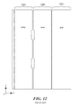
- FIGS. 11-12 show a second prior art accelerometer device configuration and corresponding electrode configuration
- FIGS. 13-14 show a first exemplary embodiment of a platform and anchoring configuration and corresponding electrode configuration
- FIGS. 15-16 show a second exemplary embodiment of a platform and anchoring configuration and corresponding electrode configuration.
- FIGS. 17A-17B schematically and conceptually shows a top view of an accelerometer, according to some embodiments.
- the accelerometer includes one or more platforms configured so as to move in proportion to deformation of the substrate and/or anchor(s).
- the platform(s) may be in a fixed position relative to the substrate, e.g., by being fixedly attached to the anchor(s) or by being fixedly attached to the substrate, or the platform(s) may be movable relative to the substrate, e.g., by being tethered to the anchor(s) so as to allow the platform(s) to pivot relative to the anchor(s) (e.g., see FIGS. 17A and 17B ).
- Electrodes are placed on the substrate underlying the platform(s) for sensing position of the platform(s) relative to the underlying substrate, which may change, for example, due to deformation of the substrate as depicted in FIG. 2 or due to tilting of the anchor as depicted in FIG. 3 .
- the teeter-totter proof mass is configured such that it can rotate relative to the platform(s), e.g., by being tethered to the platform(s) or by being tethered to one or more anchors separate from the platform(s).
- the platform(s) is/are sufficiently rigid to not change position (e.g., deformation) in the presence of an acceleration input.
- the output of the accelerometer is adjusted based on signals from these platform-sensing electrodes in order to reduce or eliminate offset drift.
- FIG. 4 schematically and conceptually shows a cross-sectional view of a Z-axis teeter-totter type accelerometer in accordance with one exemplary embodiment of the present invention
- FIG. 5 schematically and conceptually shows a top view of the accelerometer of FIG. 4
- FIG. 5(A) shows a platform 402 fixedly attached to anchor(s) 109 , with the teeter-totter proof mass 106 tethered to the platform 402 via tethers 403 (for convenience, the tethers 403 are not labeled in FIG. 5 , and it should be noted that embodiments of the present invention are not limited to any particular type or number of tethers).
- Additional electrodes 404 A and 404 B are included on the substrate 111 under the platform 402 .
- the electrodes 404 are placed symmetrically with respect to the axis of rotation underneath the platform 402 .
- FIG. 5(B) shows the relative positions of the electrodes 108 A/ 108 B and the electrodes 404 A/ 404 B relative to the platform 402 and teeter-totter proof mass 106 —the electrodes 108 A/ 108 B and 404 A/ 404 B are shown in dashed lines, as they are underneath the platform 402 and teeter-totter proof mass 106 .
- FIG. 5(B) shows the relative positions of the electrodes 108 A/ 108 B and the electrodes 404 A/ 404 B relative to the platform 402 and teeter-totter proof mass 106 —the electrodes 108 A/ 108 B and 404 A/ 404 B are shown in dashed lines, as they are underneath the platform 402 and teeter
- the location of anchor 109 is represented by a circle with an “x” in it.
- the electrodes 404 A and 404 B are used for sensing position of the platform 402 relative to the underlying substrate 111 , which may change, for example, due to deformation of the substrate as depicted in FIG. 6 in the manner described above with reference to FIG. 2 , or due to tilting of the anchor as depicted in FIG. 7 in the manner described above with reference to FIG. 3 .
- embodiments may additionally or alternatively include platform-sensing electrodes above the platform 402 , i.e., on the substrate that supports electrodes 110 .
- the teeter-totter proof mass 106 , the platform 402 , and the tethers 403 may be formed from a unitary layer of material, e.g., using MEMS fabrication processes.
- the unitary layer of material may be any appropriate material, such as, for example, polysilicon, tungsten, etc.
- the platform 402 and the anchor(s) 109 may be formed from the same material or from different materials.
- the platform 402 may be fixedly attached to the anchor(s) 109 by being integrally formed with the anchor(s) 109 or by being a separate structure that is bonded to the anchor(s) 109 .
- the platform 402 may be movably attached to the anchor(s) 109 via tethers 1703 .
- FIG. 8 schematically and conceptually shows a cross-sectional view of a Z-axis teeter-totter type accelerometer of the types discussed above.
- a device chip 102 includes a Z-axis teeter-totter type accelerometer with a teeter-totter proof mass 106 and electrodes placed on substrates both above ( 110 ) and below ( 108 ) the teeter-totter proof mass 106 .
- the device chip 102 is mechanically and electrically coupled with a circuit chip 104 .
- the teeter-totter proof mass 106 is supported above the underlying substrate by one or more anchors 109 with a platform 402 and tethers 403 allowing the teeter-totter proof mass 106 to rotate about an axis defined by the platform 402 and tethers 403 such that the ends of the teeter-totter proof mass 106 are movable in the Z-axis direction, i.e., the ends of the teeter-totter proof mass 106 can move toward and away from the electrodes 108 A/ 108 B and 110 A/ 110 B.
- Platform-sensing electrodes 404 A and 404 B are included for sensing the position of the platform 402 relative to the underlying substrate.
- Various electrical and/or mechanical connections 112 are made between the device chip 102 and the circuit chip 104 , such as for electrically coupling circuitry 105 in the circuit chip 104 with the electrodes 108 , 110 , and 404 (the electrical connections are shown as dashed lines) and the teeter-totter proof mass 106 (electrical connection not shown for convenience).
- FIG. 9 shows a first prior art accelerometer device configuration and FIG. 10 shows a corresponding electrode configuration.
- the teeter-totter proof mass 106 (only a portion shown for convenience) is tethered to a single anchor (indicated by the box marked “X”).
- the arrangement of electrodes shown in FIG. 10 is positioned on the underlying substrate so as to underlie the structures shown in FIG. 9 , with electrode 108 A underlying the device section 902 , the electrode 108 B underlying the device section 904 , and the electrode 912 underlying the device section 906 .
- the electrodes 108 A and 108 B are used to sense the relative position of the teeter-totter proof mass 106 , while the electrode 912 (labeled “pzp”) can be used for self-test and/or sensing.
- FIG. 11 shows a second prior art accelerometer device configuration and FIG. 12 shows a corresponding electrode configuration.
- the teeter-totter proof mass 106 (only a portion shown for convenience) is tethered to two anchors (indicated by the boxes marked “X”).
- the arrangement of electrodes shown in FIG. 12 is positioned on the underlying substrate so as to underlie the structures shown in FIG. 11 , with electrode 108 A underlying the device section 1002 , the electrode 108 B underlying the device section 1004 , and the electrode 1012 underlying the device section 1006 .
- the electrodes 108 A and 108 B are used to sense the relative position of the teeter-totter proof mass 106 , while the electrode 1012 (labeled “pzp”) can be used for self-test and/or sensing.
- FIG. 13 shows a first exemplary embodiment of a platform and anchoring configuration
- FIG. 14 shows a corresponding electrode configuration
- the device includes two platforms 1120 A and 1120 B supported by a single anchor (indicated by the box marked “X”), with the teeter-totter proof mass 106 (only a portion shown for convenience) tethered to the anchor so as to be pivotable about the anchor.
- the arrangement of electrodes shown in FIG. 14 is positioned on the underlying substrate so as to underlie the structures shown in FIG. 13 , with electrode section 1108 underlying the device section 1102 , the electrode section 1110 underlying the device section 1104 , and the electrode section 1112 underlying the device section 1106 .
- the electrodes 108 A and 108 B are used to sense the relative position of the teeter-totter proof mass 106
- the electrodes 404 A and 404 B are used to sense any displacement of platforms 1120 A and 1120 B, respectively
- the electrode labeled “pzp” can be used for self-test and/or sensing.
- FIG. 15 shows a second exemplary embodiment of a platform and anchoring configuration
- FIG. 16 shows a corresponding electrode configuration
- the device includes two platforms 1320 A and 1320 B supported by a two anchors (indicated by the boxes marked “X”), with the teeter-totter proof mass 106 (only a portion shown for convenience) tethered to the anchors so as to be pivotable about the anchors.
- the arrangement of electrodes shown in FIG. 16 is positioned on the underlying substrate so as to underlie the structures shown in FIG. 15 , with electrode section 1308 underlying the device section 1302 , the electrode section 1310 underlying the device section 1304 , and the electrode section 1312 underlying the device section 1306 .
- the electrodes 108 A and 108 B are used to sense the relative position of the teeter-totter proof mass 106
- the electrodes 404 A and 404 B are used to sense any displacement of platforms 1320 A and 1320 B, respectively
- the electrode labeled “pzp” can be used for self-test and/or sensing.
- the accelerometer output would be adjusted by a factor of ((zpos ⁇ zneg)+(zneg_comp ⁇ zpos_comp)).
- FIGS. 13 and 15 are highlighted by border lines that show the general shape and perimeter location of these structures, although it should be noted that, because the device layer containing these structures is generally formed from a unitary layer of material, the actual boundaries of the various structures may be different than what is shown. In any case, the teeter-totter proof mass 106 is configured to be able to move relative to the platforms.
- platform-sensing electrodes underlying both sides of the platform, i.e., on both sides of the anchor(s)
- certain alternative embodiments include a platform-sensing electrode on only one side of the platform, with such platform-sensing electrode still capable of sensing the relative position of the platform.
- embodiments of the present invention can include a device chip containing the accelerometer mechanical components separate from the circuit chip, a circuit chip that contains the accelerometer output circuitry separate from the device chip, or an integrated device including the device chip and the circuit chip. It also should be noted that accelerometer output circuitry that provides an accelerometer output based on the sense electrode(s) and the platform-sensing electrode(s) can be included in the device chip along with the accelerometer mechanical components.
Abstract
A teeter-totter type accelerometer includes one or more platforms configured so as to move in proportion to deformation of the substrate and/or anchor(s). The platform(s) may be in a fixed position relative to the substrate, e.g., by being fixedly attached to the anchor(s) or by being fixedly attached to the substrate, or the platform(s) may be movable relative to the substrate, e.g., by being tethered to the anchor(s) so as to allow the platform(s) to pivot relative to the anchor(s). Electrodes are placed on the substrate underlying the platform(s) for sensing position of the platform(s) relative to the underlying substrate. The teeter-totter proof mass is configured such that it can rotate relative to the platform(s), e.g., by being tethered to the platform(s) or by being tethered to one or more anchors separate from the platform(s). The output of the accelerometer is adjusted based on signals from these platform-sensing electrodes in order to reduce or eliminate offset drift.
Description
The subject matter of this patent application may be related to one of more of the following patent applications, each of which is hereby incorporated herein by reference in its entirety:
U.S. patent application Ser. No. 13/523,101 entitled Teeter-Totter Type MEMS Accelerometer with Electrodes on Circuit Wafer filed on Jun. 14, 2012 and published as US 2013/0333471;
U.S. patent application Ser. No. 13/910,755 entitled MEMS Sensor With Dynamically Variable Reference Capacitance filed on Jun. 5, 2013;
U.S. patent application Ser. No. 13/751,387 entitled Teeter Totter Accelerometer with Unbalanced Mass filed on Jan. 28, 2013 and published as US 2014/0208849;
U.S. patent application Ser. No. 13/785,624 entitled Tilt Mode Accelerometer with Improved Offset and Noise Performance filed on Mar. 5, 2013 and published as US 2014/0251011; and
U.S. patent application Ser. No. 14/505,928 entitled MEMS Accelerometer with Z Axis Anchor Tracking filed on Oct. 3, 2014.
The present invention relates generally to Z-axis accelerometers of the type often referred to as “teeter-totter” type accelerometers.
An accelerometer is a type of transducer that converts acceleration forces into electronic signals. Accelerometers are used in a wide variety of devices and for a wide variety of applications. For example, accelerometers are often included various automobile systems, such as for air-bag deployment and roll-over detection. Accelerometers are often also included in many computer devices, such as for motion-based sensing (e.g., drop detection) and control (e.g., motion-based control for gaming).
Generally speaking, a MEMS (Micro Electro Mechanical System) accelerometer typically includes, among other things, a proof mass and one or more structures for sensing movement or changes in position of the proof mass induced by external accelerations. Accelerometers can be configured to sense one, two, three, or even more axes of acceleration. Typically, the proof mass is configured in a predetermined device plane, and the axes of sensitivity are generally referred to with respect to this device plane. For example, accelerations sensed along an axis parallel to the device plane are typically referred to as X or Y axis accelerations, while accelerations sensed along an axis perpendicular to the device plane are typically referred to as Z axis accelerations. A single-axis accelerometer might be configured to detect just X or Y axis accelerations or just Z axis accelerations. A two-axis accelerometer might be configured to detect X and Y axis accelerations or might be configured to detect X and Z axis accelerations. A three-axis accelerometer might be configured to detect X, Y, and Z axis accelerations.
One category of Z-axis accelerometer uses a proof mass that is configured in a “teeter-totter,” “see-saw,” or “tilt mode” configuration, where the proof mass is supported from a substrate such that the proof mass rotates relative to the substrate under Z-axis acceleration. Sense electrodes placed below (e.g., on the underlying substrate) or both above and below the proof mass, which in many types of accelerometers are capacitively coupled with the proof mass, are used to sense such rotation of the proof mass and thereby to sense Z-axis acceleration. Other electrical components, such as feedback electrodes, also may be included below and/or above the proof mass. U.S. Pat. No. 7,610,809 provides an example of a differential teeter-totter type Z-axis accelerometer having electrodes both above and below the proof mass. U.S. Pat. No. 6,841,992 and U.S. Pat. No. 5,719,336 provide other examples of such teeter-totter type accelerometers. U.S. Pat. No. 8,146,425 describes a MEMS sensor with movable z-axis sensing element. Each of these patents is hereby incorporated by reference in its entirety.
In some teeter-totter type accelerometers, sense electrodes are placed only above or below the teeter-totter proof mass. For example, an alternative teeter-totter type accelerometer may include only electrodes 108 or only electrodes 110. Again, the output of the accelerometer may be a combination of the signals from the sense electrodes processed in a differential fashion, e.g., Output=(C_108A−C_108B) or Output=(C_110A−C_110B).
In some teeter-totter type accelerometers, only one sense electrode is used to sense movement of the teeter-totter proof mass. For example, a single sense electrode may be positioned toward one end of the teeter-totter proof mass.
In some teeter-totter accelerometers, the teeter-totter proof mass is “unbalanced” in that it extends further on one side of the anchor(s) than the other side of the anchor(s). In such accelerometers, a sense electrode may be positioned toward the end of the extended portion of the teeter-totter proof mass.
While two electrodes are shown both above and below the proof mass 106 in this schematic drawing, it should be noted that additional electrodes (e.g., feedback electrodes) also may be included in the electrode layers above and/or below the proof mass 106. Thus, for example, each electrode layer may include two or more sense electrodes and one or more feedback electrodes. Various electrical and/or mechanical connections 112 are made between the device chip 102 and the circuit chip 104, such as for electrically coupling circuitry 105 in the circuit chip 104 with the top and bottom sets of electrodes 108, 110 (the electrical connections are shown as dashed lines) and the teeter-totter proof mass 106 (electrical connection not shown for convenience). The accelerometer may be operated, for example, substantially as described in U.S. Pat. No. 7,610,809 (McNeil).
U.S. Pat. No. 8,146,425 (Zhang) discloses a MEMS sensor with movable Z-axis sensing element.
US 2013/0333471 (Chien) discloses a teeter-totter type MEMS accelerometer with electrodes on the circuit wafer.
US 2014/0208849 (Zhang) discloses a teeter totter accelerometers with unbalanced mass.
US 2014/0251011 (Zhang) discloses a tilt mode accelerometer with improved offset and noise performance.
Certain conditions (e.g., mechanical stresses, temperature variations, and other mechanical effects that change the position of the teeter-totter proof mass relative to one or more sense electrodes, such as by deformation of the substrate/package) can cause a phenomenon often referred to as “offset drift,” where the accelerometer can output signals that indicate an erroneous amount of acceleration. For example, the accelerometer may output signals indicating the presence of acceleration when no acceleration exists, may output signals indicating absence of acceleration when acceleration does exist, or may output signals indicating an incorrect amount of acceleration.
It should be noted that, for convenience, FIGS. 2 and 3 show only underlying electrodes 108. In accelerometers that include overlying electrodes 110, offset drift can be caused by changes in the nominal distances between the electrodes 110 and the teeter-totter proof mass, e.g., due to stresses in the overlying substrate that supports the electrodes 110.
Some prior attempts to address offset drift from such conditions include mechanically and/or electronically deflecting the anchor(s), pivot(s), or the teeter-totter proof mass itself so as to counteract deformations of the substrate or anchor(s).
In accordance with one embodiment of the invention, a teeter-totter type accelerometer comprises a substrate; at least one anchor supported by the substrate; at least one platform supported by the substrate; a teeter-totter proof mass configured for pivoting about the at least one anchor in the presence of accelerations that are in a direction normal to the substrate; at least one sense electrode positioned to allow for sensing such pivoting of the teeter-totter proof mass; and at least one platform-sensing electrode positioned to allow for sensing position of the platform relative to the substrate.
In various alternative embodiments, the at least one platform may be fixedly attached to the at least one anchor, may be tethered to the at least one anchor such that the at least one platform is capable of pivoting about the at least one anchor, or may be fixedly attached to the substrate. The teeter-totter proof mass may be tethered to the at least one platform or to the at least one anchor. Some embodiments include a single anchor, while other embodiments include two or more anchors. Some embodiments include a single platform, while other embodiments include two or more platforms. The at least one platform-sensing electrode may include a first platform-sensing electrode positioned to a first side of the at least one anchor and a second platform-sensing electrode positioned to a second side of the at least one anchor opposite the first side. The teeter-totter proof mass may be an unbalanced teeter-totter proof mass.
In certain embodiments, the teeter-totter type accelerometer also includes an accelerometer output circuit configured to produce an accelerometer output signal based on signals received from the at least one sense electrode and the at least one platform-sensing electrode. In some embodiments, the mechanical components including the substrate, the at least one anchor, the at least one platform, the teeter-totter proof mass, the at least one sense electrode, and the at least one platform-sensing electrode are in a device chip, while the accelerometer output circuit is in a circuit chip attached to the device chip.
In accordance with another embodiment of the invention, an accelerometer output circuit for a teeter-totter type accelerometer of the types described above is configured to receive signals from the at least one sense electrode and the at least one platform-sensing electrode and to produce an accelerometer output signal based on the signals received from the at least one sense electrode and the at least one platform-sensing electrode.
In accordance with another embodiment of the invention, a circuit chip for a teeter-totter type accelerometer of the types described above comprises an accelerometer output circuit configured to receive signals from the at least one sense electrode and the at least one platform-sensing electrode and to produce an accelerometer output signal based on the signals received from the at least one sense electrode and the at least one platform-sensing electrode.
In any of the above embodiments, the at least one platform-sensing electrode may include a first platform-sensing electrode positioned to a first side of the at least one anchor and a second platform-sensing electrode positioned to a second side of the at least one anchor opposite the first side, in which case the accelerometer output circuit may be configured to receive signals from the first and second platform-sensing electrodes and produce the accelerometer output signal based on a difference between the signals received from the first and second platform-sensing electrodes.
Additional embodiments may be disclosed and claimed.
The foregoing features of embodiments will be more readily understood by reference to the following detailed description, taken with reference to the accompanying drawings, in which:
It should be noted that the foregoing figures and the elements depicted therein are not necessarily drawn to consistent scale or to any scale. Unless the context otherwise suggests, like elements are indicated by like numerals.
In embodiments of the present invention, the accelerometer includes one or more platforms configured so as to move in proportion to deformation of the substrate and/or anchor(s). The platform(s) may be in a fixed position relative to the substrate, e.g., by being fixedly attached to the anchor(s) or by being fixedly attached to the substrate, or the platform(s) may be movable relative to the substrate, e.g., by being tethered to the anchor(s) so as to allow the platform(s) to pivot relative to the anchor(s) (e.g., see FIGS. 17A and 17B ). Electrodes are placed on the substrate underlying the platform(s) for sensing position of the platform(s) relative to the underlying substrate, which may change, for example, due to deformation of the substrate as depicted in FIG. 2 or due to tilting of the anchor as depicted in FIG. 3 . The teeter-totter proof mass is configured such that it can rotate relative to the platform(s), e.g., by being tethered to the platform(s) or by being tethered to one or more anchors separate from the platform(s). The platform(s) is/are sufficiently rigid to not change position (e.g., deformation) in the presence of an acceleration input. The output of the accelerometer is adjusted based on signals from these platform-sensing electrodes in order to reduce or eliminate offset drift.
It should be noted that other embodiments may additionally or alternatively include platform-sensing electrodes above the platform 402, i.e., on the substrate that supports electrodes 110.
It also should be noted that the teeter-totter proof mass 106, the platform 402, and the tethers 403 may be formed from a unitary layer of material, e.g., using MEMS fabrication processes. The unitary layer of material may be any appropriate material, such as, for example, polysilicon, tungsten, etc.
It also should be noted that the platform 402 and the anchor(s) 109 may be formed from the same material or from different materials. The platform 402 may be fixedly attached to the anchor(s) 109 by being integrally formed with the anchor(s) 109 or by being a separate structure that is bonded to the anchor(s) 109. In some embodiments, as shown in FIGS. 17A and 17B , the platform 402 may be movably attached to the anchor(s) 109 via tethers 1703.
For the accelerometers shown in FIGS. 13-16 , the accelerometer output would be adjusted by a factor of ((zpos−zneg)+(zneg_comp−zpos_comp)).
It should be noted that the platforms in FIGS. 13 and 15 are highlighted by border lines that show the general shape and perimeter location of these structures, although it should be noted that, because the device layer containing these structures is generally formed from a unitary layer of material, the actual boundaries of the various structures may be different than what is shown. In any case, the teeter-totter proof mass 106 is configured to be able to move relative to the platforms.
Even though the exemplary embodiments described above include platform-sensing electrodes underlying both sides of the platform, i.e., on both sides of the anchor(s), it should be noted that certain alternative embodiments include a platform-sensing electrode on only one side of the platform, with such platform-sensing electrode still capable of sensing the relative position of the platform.
It should be noted that embodiments of the present invention can include a device chip containing the accelerometer mechanical components separate from the circuit chip, a circuit chip that contains the accelerometer output circuitry separate from the device chip, or an integrated device including the device chip and the circuit chip. It also should be noted that accelerometer output circuitry that provides an accelerometer output based on the sense electrode(s) and the platform-sensing electrode(s) can be included in the device chip along with the accelerometer mechanical components.
The present invention may be embodied in other specific forms without departing from the true scope of the invention, and numerous variations and modifications will be apparent to those skilled in the art based on the teachings herein. Any references to the “invention” are intended to refer to exemplary embodiments of the invention and should not be construed to refer to all embodiments of the invention unless the context otherwise requires. The described embodiments are to be considered in all respects only as illustrative and not restrictive.
Claims (19)
1. A teeter-totter type accelerometer comprising:
a substrate;
at least one anchor supported by the substrate;
at least one platform supported by the substrate;
a teeter-totter proof mass coupled to the at least one platform by at least one spring and configured for pivoting about an axis of rotation through the at least one anchor in the presence of accelerations that are in a direction normal to the substrate, wherein the at least one spring is off-axis with the axis of rotation of the proof mass;
at least one sense electrode positioned to allow for sensing such pivoting of the teeter-totter proof mass; and
at least one platform-sensing electrode positioned to allow for sensing position of the platform relative to the substrate.
2. A teeter-totter type accelerometer according to claim 1 , wherein the at least one platform is fixedly attached to the at least one anchor.
3. A teeter-totter type accelerometer according to claim 2 , wherein the at least one platform is integrally formed with the at least one anchor.
4. A teeter-totter type accelerometer according to claim 1 , wherein the at least one platform is disposed within an opening of the teeter-totter proof mass.
5. A teeter-totter type accelerometer according to claim 1 , wherein the at least one platform is fixedly attached to the substrate.
6. A teeter-totter type accelerometer according to claim 1 , wherein the teeter-totter proof mass is tethered to the at least one platform.
7. A teeter-totter type accelerometer according to claim 1 , wherein the teeter-totter proof mass is tethered to the at least one anchor.
8. A teeter-totter type accelerometer according to claim 1 , wherein the at least one platform comprises a plurality of platforms.
9. A teeter-totter type accelerometer according to claim 1 , wherein the at least one anchor comprises a plurality of anchors.
10. A teeter-totter type accelerometer according to claim 1 , wherein the at least one platform-sensing electrode comprises:
a first platform-sensing electrode positioned to a first side of the at least one anchor; and
a second platform-sensing electrode positioned to a second side of the at least one anchor opposite the first side.
11. A teeter-totter type accelerometer according to claim 1 , wherein the teeter-totter proof mass is an unbalanced teeter-totter proof mass.
12. A teeter-totter type accelerometer according to claim 1 , further comprising:
an accelerometer output circuit configured to produce an accelerometer output signal based on signals received from the at least one sense electrode and the at least one platform-sensing electrode.
13. A teeter-totter type accelerometer according to claim 12 , wherein the substrate, the at least one anchor, the at least one platform, the teeter-totter proof mass, the at least one sense electrode, and the at least one platform-sensing electrode are in a device chip, and wherein the accelerometer output circuit is in a circuit chip attached to the device chip.
14. A teeter-totter type accelerometer according to claim 1 , wherein the at least one platform-sensing electrode comprises:
a first pair of platform-sensing electrodes positioned to a first side of the at least one anchor; and
a second pair of platform-sensing electrodes positioned to a second side of the at least one anchor opposite the first side.
15. An accelerometer output circuit for a teeter-totter type accelerometer having a substrate, at least one anchor supported by the substrate, a platform attached to the at least one anchor, a teeter-totter proof mass coupled to the platform by at least one spring such that the teeter-totter proof mass is capable of pivoting about an axis of rotation through the at least one anchor in the presence of accelerations that are in a direction normal to the substrate, wherein the at least one spring is off-axis with the axis of rotation of the proof mass, at least one sense electrode positioned to allow for sensing such pivoting of the teeter-totter proof mass, and at least one platform-sensing electrode positioned to allow for sensing position of the platform relative to the substrate, the accelerometer output circuit configured to receive signals from the at least one sense electrode and the at least one platform-sensing electrode and to produce an accelerometer output signal based on the signals received from the at least one sense electrode and the at least one platform-sensing electrode.
16. An accelerometer output circuit according to claim 15 , wherein the at least one platform-sensing electrode comprises a first platform-sensing electrode positioned to a first side of the at least one anchor and a second platform-sensing electrode positioned to a second side of the at least one anchor opposite the first side, and wherein the accelerometer output circuit is configured to receive signals from the first and second platform-sensing electrodes and produce the accelerometer output signal based on a difference between the signals received from the first and second platform-sensing electrodes.
17. An accelerometer output circuit according to claim 15 , wherein the at least one platform-sensing electrode comprises a first pair of platform-sensing electrodes positioned to a first side of the at least one anchor and a second pair or platform-sensing electrodes positioned to a second side of the at least one anchor opposite the first side, and
wherein the accelerometer output circuit is configured to receive signals from the first and second pairs of platform-sensing electrodes and produce the accelerometer output signal based on a difference between the signals received from the first and second pairs of platform-sensing electrodes.
18. A teeter-totter type accelerometer comprising:
a substrate;
at least one anchor supported by the substrate;
at least one platform supported by the substrate, the at least one platform being coupled to the at least one anchor by at least one first tether and configured for pivoting about the at least one anchor;
a teeter-totter proof mass coupled to the at least one platform by at least one second tether and configured for pivoting about the at least one anchor in the presence of accelerations that are in a direction normal to the substrate;
at least one sense electrode positioned to allow for sensing such pivoting of the teeter-totter proof mass; and
at least one platform-sensing electrode positioned to allow for sensing position of the platform relative to the substrate.
19. The teeter-totter type accelerometer of claim 18 , wherein the at least one platform is disposed within an opening of the teeter-totter proof mass.
Priority Applications (3)
| Application Number | Priority Date | Filing Date | Title |
|---|---|---|---|
| US14/747,456 US10078098B2 (en) | 2015-06-23 | 2015-06-23 | Z axis accelerometer design with offset compensation |
| CN201610225944.8A CN106290984B (en) | 2015-06-23 | 2016-04-13 | Z-axis accelerometer with offset exaggerate compensation |
| DE102016109328.9A DE102016109328B4 (en) | 2015-06-23 | 2016-05-20 | Z-axis accelerometer design with offset compensation |
Applications Claiming Priority (1)
| Application Number | Priority Date | Filing Date | Title |
|---|---|---|---|
| US14/747,456 US10078098B2 (en) | 2015-06-23 | 2015-06-23 | Z axis accelerometer design with offset compensation |
Publications (2)
| Publication Number | Publication Date |
|---|---|
| US20160377648A1 US20160377648A1 (en) | 2016-12-29 |
| US10078098B2 true US10078098B2 (en) | 2018-09-18 |
Family
ID=57537126
Family Applications (1)
| Application Number | Title | Priority Date | Filing Date |
|---|---|---|---|
| US14/747,456 Active US10078098B2 (en) | 2015-06-23 | 2015-06-23 | Z axis accelerometer design with offset compensation |
Country Status (3)
| Country | Link |
|---|---|
| US (1) | US10078098B2 (en) |
| CN (1) | CN106290984B (en) |
| DE (1) | DE102016109328B4 (en) |
Cited By (1)
| Publication number | Priority date | Publication date | Assignee | Title |
|---|---|---|---|---|
| US11714102B2 (en) | 2021-06-08 | 2023-08-01 | Analog Devices, Inc. | Fully differential accelerometer |
Families Citing this family (22)
| Publication number | Priority date | Publication date | Assignee | Title |
|---|---|---|---|---|
| US10203351B2 (en) | 2014-10-03 | 2019-02-12 | Analog Devices, Inc. | MEMS accelerometer with Z axis anchor tracking |
| US11231441B2 (en) * | 2015-05-15 | 2022-01-25 | Invensense, Inc. | MEMS structure for offset minimization of out-of-plane sensing accelerometers |
| US10203352B2 (en) | 2016-08-04 | 2019-02-12 | Analog Devices, Inc. | Anchor tracking apparatus for in-plane accelerometers and related methods |
| US10261105B2 (en) * | 2017-02-10 | 2019-04-16 | Analog Devices, Inc. | Anchor tracking for MEMS accelerometers |
| EP3583386B1 (en) * | 2017-02-17 | 2021-03-24 | InvenSense, Inc. | Anchoring structure for a sensor insensitive to anchor movement |
| JP6911444B2 (en) * | 2017-03-27 | 2021-07-28 | セイコーエプソン株式会社 | Physical quantity sensors, electronics, and mobiles |
| US10816569B2 (en) | 2018-09-07 | 2020-10-27 | Analog Devices, Inc. | Z axis accelerometer using variable vertical gaps |
| US11255873B2 (en) | 2018-09-12 | 2022-02-22 | Analog Devices, Inc. | Increased sensitivity z-axis accelerometer |
| US11099207B2 (en) * | 2018-10-25 | 2021-08-24 | Analog Devices, Inc. | Low-noise multi-axis accelerometers and related methods |
| US11528808B2 (en) | 2018-12-03 | 2022-12-13 | X Display Company Technology Limited | Printing components to substrate posts |
| US11482979B2 (en) | 2018-12-03 | 2022-10-25 | X Display Company Technology Limited | Printing components over substrate post edges |
| CN109444465A (en) * | 2018-12-29 | 2019-03-08 | 深迪半导体(上海)有限公司 | A kind of accelerometer |
| JP7135901B2 (en) * | 2019-01-31 | 2022-09-13 | セイコーエプソン株式会社 | Inertial sensors, electronics and vehicles |
| JP6870761B2 (en) | 2019-05-15 | 2021-05-12 | 株式会社村田製作所 | Robust Z-axis accelerometer |
| WO2021050238A1 (en) * | 2019-09-11 | 2021-03-18 | Invensense, Inc. | Mems structure for offset minimization of out-of-plane sensing accelerometers |
| CN110501522B (en) * | 2019-09-16 | 2022-10-11 | 上海矽睿科技股份有限公司 | Capacitive accelerometer of micro-electro-mechanical system |
| EP4123313A1 (en) * | 2021-07-23 | 2023-01-25 | STMicroelectronics S.r.l. | Closed-loop microelectromechanical accelerometer with compensation of spurious vibration modes and process for manufacturing a microelectromechanical accelerometer |
| CN114264844A (en) * | 2021-12-21 | 2022-04-01 | 苏州感测通信息科技有限公司 | MEMS accelerometer with stress compensation function |
| CN113970655B (en) * | 2021-12-23 | 2022-04-12 | 杭州麦新敏微科技有限责任公司 | MEMS accelerometer and forming method thereof |
| CN114994363B (en) * | 2022-07-20 | 2022-11-18 | 苏州敏芯微电子技术股份有限公司 | MEMS inertial sensing structure and manufacturing method thereof |
| CN115436660A (en) * | 2022-08-31 | 2022-12-06 | 瑞声开泰科技(武汉)有限公司 | Accelerometer |
| CN115453146A (en) * | 2022-09-23 | 2022-12-09 | 瑞声开泰科技(武汉)有限公司 | Capacitive micro-machined accelerometer |
Citations (80)
| Publication number | Priority date | Publication date | Assignee | Title |
|---|---|---|---|---|
| US4598585A (en) | 1984-03-19 | 1986-07-08 | The Charles Stark Draper Laboratory, Inc. | Planar inertial sensor |
| US4670092A (en) | 1986-04-18 | 1987-06-02 | Rockwell International Corporation | Method of fabricating a cantilever beam for a monolithic accelerometer |
| US4736629A (en) * | 1985-12-20 | 1988-04-12 | Silicon Designs, Inc. | Micro-miniature accelerometer |
| US4869107A (en) | 1986-08-06 | 1989-09-26 | Nissan Motor Co., Ltd. | Acceleration sensor for use in automotive vehicle |
| JPH05248976A (en) | 1992-01-06 | 1993-09-28 | Omron Corp | Capacitance sensing circuit for electrostatic capacitance varying type sensor |
| JPH05340956A (en) | 1992-06-04 | 1993-12-24 | Nippondenso Co Ltd | Acceleration sensor |
| US5331853A (en) | 1991-02-08 | 1994-07-26 | Alliedsignal Inc. | Micromachined rate and acceleration sensor |
| US5352918A (en) | 1992-02-20 | 1994-10-04 | Sextant Avionique | Capacitative micro-sensor with a low stray capacity and manufacturing method |
| WO1995024652A1 (en) | 1994-03-08 | 1995-09-14 | Neukermans Armand P | Monolithic silicon rate-gyro with integrated sensors |
| JPH09189716A (en) | 1995-11-07 | 1997-07-22 | Temic Telefunken Microelectron Gmbh | Microminiature mechanical acceleration sensor |
| US5719069A (en) | 1994-09-14 | 1998-02-17 | Delco Electronics Corporation | One-chip integrated sensor process |
| US5719336A (en) | 1995-05-18 | 1998-02-17 | Aisin Seiki Kabushiki Kaisha | Capacitive acceleration sensor |
| US5864063A (en) | 1996-09-12 | 1999-01-26 | Mitsubishi Denki Kabushiki Kaisha | Electrostatic capacity-type acceleration sensor |
| EP0951068A1 (en) | 1998-04-17 | 1999-10-20 | Interuniversitair Micro-Elektronica Centrum Vzw | Method of fabrication of a microstructure having an inside cavity |
| US6158280A (en) | 1997-12-22 | 2000-12-12 | Kabushiki Kaisha Toyota Chuo Kenkyusho | Detector for detecting angular velocities about perpendicular axes |
| US6230566B1 (en) | 1999-10-01 | 2001-05-15 | The Regents Of The University Of California | Micromachined low frequency rocking accelerometer with capacitive pickoff |
| US6308569B1 (en) | 1999-07-30 | 2001-10-30 | Litton Systems, Inc. | Micro-mechanical inertial sensors |
| US6405592B1 (en) | 1997-06-19 | 2002-06-18 | Stmicrlelectronics S.R.L. | Hermetically-sealed sensor with a movable microstructure |
| US6651500B2 (en) | 2001-10-03 | 2003-11-25 | Litton Systems, Inc. | Micromachined silicon tuned counterbalanced accelerometer-gyro with quadrature nulling |
| US20040160232A1 (en) | 2003-02-18 | 2004-08-19 | Honeywell International, Inc. | MEMS enhanced capacitive pick-off and electrostatic rebalance electrode placement |
| JP2004340716A (en) | 2003-05-15 | 2004-12-02 | Mitsubishi Electric Corp | Acceleration sensor |
| US6892576B2 (en) | 2002-07-19 | 2005-05-17 | Analog Devices, Inc. | Reducing offset in accelerometers |
| US20050109109A1 (en) | 2003-11-20 | 2005-05-26 | Honeywell International, Inc. | Capacitive pick-off and electrostatic rebalance accelerometer having equalized gas damping |
| JP2005529336A (en) | 2002-06-11 | 2005-09-29 | コンティ テミック マイクロエレクトロニック ゲゼルシャフト ミット ベシュレンクテル ハフツング | Multi-axis monolithic acceleration sensor |
| US20050268719A1 (en) | 2004-06-07 | 2005-12-08 | Honeywell International, Inc. | Dynamically balanced capacitive pick-off accelerometer |
| WO2006023476A1 (en) | 2004-08-17 | 2006-03-02 | Analog Devices, Inc. | Multiple axis acceleration sensor |
| US20060169043A1 (en) | 2005-01-28 | 2006-08-03 | Mcneil Andrew C | Z-axis accelerometer with at least two gap sizes and travel stops disposed outside an active capacitor area |
| US20060185433A1 (en) | 2005-02-18 | 2006-08-24 | Honeywell International, Inc. | MEMS teeter-totter accelerometer having reduced non-linearty |
| US20070000323A1 (en) | 2005-06-17 | 2007-01-04 | Vti Technologies Oy | Method of manufacturing a capacitive acceleration sensor, and a capacitive acceleration sensor |
| US7210352B2 (en) | 2005-06-14 | 2007-05-01 | Innovative Micro Technology | MEMS teeter-totter apparatus with curved beam and method of manufacture |
| EP1808405A2 (en) | 2006-01-13 | 2007-07-18 | Honeywell International Inc. | Integrated package for MEMS die and IC chip |
| US20080110260A1 (en) | 2006-11-09 | 2008-05-15 | Mitsubishi Electric Corporation | Acceleration sensor |
| JP2008139282A (en) | 2006-11-09 | 2008-06-19 | Mitsubishi Electric Corp | Acceleration sensor |
| WO2008086530A2 (en) | 2007-01-11 | 2008-07-17 | Analog Devices, Inc. | Mems sensor with cap electrode |
| WO2008133183A1 (en) | 2007-04-20 | 2008-11-06 | Alps Electric Co., Ltd. | Capacitance type acceleration sensor |
| US20090031809A1 (en) | 2007-08-03 | 2009-02-05 | Freescale Semiconductor, Inc. | Symmetrical differential capacitive sensor and method of making same |
| US20090139331A1 (en) | 2007-11-15 | 2009-06-04 | Physical Logic Ag | Accelerometer |
| US20090145229A1 (en) | 2007-12-07 | 2009-06-11 | Metamems Llc | Decelerometer formed by levitating a substrate into equilibrium |
| CN101568840A (en) | 2006-12-27 | 2009-10-28 | 罗伯特·博世有限公司 | Multi-axle micromechanic acceleration sensor |
| US7610809B2 (en) | 2007-01-18 | 2009-11-03 | Freescale Semiconductor, Inc. | Differential capacitive sensor and method of making same |
| US20090293616A1 (en) | 2008-05-29 | 2009-12-03 | Freescale Semiconductor, Inc. | capacitive sensor with stress relief that compensates for package stress |
| US20100011860A1 (en) | 2008-07-18 | 2010-01-21 | Michael Offenberg | Micromechanical sensor element, method for manufacturing a micromechanical sensor element and method for operating a micromechanical sensor element |
| US20100024552A1 (en) | 2008-07-31 | 2010-02-04 | Honeywell International Inc. | Systems and methods for detecting out-of-plane linear acceleration with a closed loop linear drive accelerometer |
| WO2010027600A2 (en) | 2008-09-05 | 2010-03-11 | Analog Devices, Inc. | Mems sensor with movable z-axis sensing element |
| US20100107763A1 (en) | 2008-10-30 | 2010-05-06 | Freescale Semiconductor, Inc. | Transducer with decoupled sensing in mutually orthogonal directions |
| WO2010055716A1 (en) | 2008-11-13 | 2010-05-20 | 三菱電機株式会社 | Acceleration sensor |
| US20100122579A1 (en) | 2008-11-18 | 2010-05-20 | Industrial Technology Research Institute | Multi-axis capacitive accelerometer |
| US7736931B1 (en) | 2009-07-20 | 2010-06-15 | Rosemount Aerospace Inc. | Wafer process flow for a high performance MEMS accelerometer |
| JP2010210425A (en) | 2009-03-10 | 2010-09-24 | Panasonic Electric Works Co Ltd | Acceleration sensor |
| US20100242603A1 (en) | 2009-03-24 | 2010-09-30 | Freescale Semiconductor, Inc. | Vertically integrated mems sensor device with multi-stimulus sensing |
| US20100242600A1 (en) | 2009-03-24 | 2010-09-30 | Freescale Semiconductor, Inc. | Vertically integrated mems acceleration transducer |
| US20100300204A1 (en) * | 2009-05-26 | 2010-12-02 | Jochen Reinmuth | Acceleration sensor |
| US20100313660A1 (en) | 2009-06-15 | 2010-12-16 | Rohm Co., Ltd. | Mems device and method of fabricating the mems device |
| US20110023606A1 (en) | 2008-04-03 | 2011-02-03 | Continental Teves Ag & Co.Ohg | Micromechanical acceleration sensor |
| US20110056295A1 (en) | 2009-09-04 | 2011-03-10 | Johannes Classen | Micromechanical system |
| US20110056297A1 (en) | 2009-09-08 | 2011-03-10 | Johannes Classen | Micromechanical system for detecting an acceleration |
| DE102009045645A1 (en) | 2009-10-13 | 2011-04-14 | Robert Bosch Gmbh | Sensor device has base plate, inertial mass and spring, where distance of counter electrode from rotation axis is less than distance of another counter electrode from rotational axis |
| US20110154899A1 (en) | 2008-04-29 | 2011-06-30 | Johannes Classen | Micromechanical component and method for operating a micromechanical component |
| US20110290023A1 (en) | 2010-05-26 | 2011-12-01 | Seiko Epson Corporation | Element structure, inertia sensor, and electronic device |
| US20110296917A1 (en) | 2010-06-02 | 2011-12-08 | Jochen Reinmuth | Micromechanical component having a test structure for determining the layer thickness of a spacer layer and method for manufacturing such a test structure |
| EP2479579A1 (en) | 2011-01-24 | 2012-07-25 | Freescale Semiconductor, Inc. Are | Mems sensor with dual proof masses |
| US20120216616A1 (en) | 2011-02-24 | 2012-08-30 | Freescale Semiconductor, Inc. | MEMS Device With Enhanced Resistance to Stiction |
| CN102714190A (en) | 2010-01-18 | 2012-10-03 | 马维尔国际贸易有限公司 | Package assembly having a semiconductor substrate |
| US20120265481A1 (en) | 2011-04-13 | 2012-10-18 | Stewart Robert E | Accelerometer systems and methods |
| US20120280591A1 (en) | 2011-05-05 | 2012-11-08 | Freescale Semiconductor, Inc. | Mems device with impacting structure for enhanced resistance to stiction |
| US20130167641A1 (en) | 2011-12-28 | 2013-07-04 | Maxim Integrated Products, Inc. | Mems acceleration sensor |
| WO2013188662A1 (en) | 2012-06-14 | 2013-12-19 | Analog Devices, Inc. | Teeter-totter type mems accelerometer with electrodes on circuit wafer |
| US20140074418A1 (en) | 2012-09-13 | 2014-03-13 | Freescale Semiconductor, Inc. | Method and system for calibrating an inertial sensor |
| CN103645342A (en) | 2013-12-06 | 2014-03-19 | 杭州士兰微电子股份有限公司 | Multiaxial capacitive accelerometer and acceleration detection method |
| US20140208849A1 (en) | 2013-01-28 | 2014-07-31 | Analog Devices, Inc. | Teeter Totter Accelerometer with Unbalanced Mass |
| US20140217929A1 (en) | 2013-02-06 | 2014-08-07 | Yizhen Lin | Stiction resistant mems device and method of operation |
| US20140251011A1 (en) | 2013-03-05 | 2014-09-11 | Analog Devices, Inc. | Tilt Mode Accelerometer with improved Offset and Noise Performance |
| US20140252509A1 (en) * | 2013-03-05 | 2014-09-11 | Stmicroelectronics S.R.L. | Mems device and corresponding micromechanical structure with integrated compensation of thermo-mechanical stress |
| CN104105945A (en) | 2012-01-31 | 2014-10-15 | 快捷半导体公司 | MEMS multi-axis accelerometer electrode structure |
| CN104237562A (en) | 2013-06-24 | 2014-12-24 | 飞思卡尔半导体公司 | Angular rate sensor with quadrature error compensation |
| US20150053002A1 (en) | 2013-08-26 | 2015-02-26 | Robert Bosch Gmbh | Micromechanical sensor and method for manufacturing a micromechanical sensor |
| US20150096378A1 (en) | 2013-10-03 | 2015-04-09 | Seiko Epson Corporation | Physical quantity detection element, physical quantity detection device, electronic apparatus, and moving object |
| US20150355222A1 (en) | 2012-06-05 | 2015-12-10 | Analog Devices, Inc. | MEMS Sensor With Dynamically Variable Reference Capacitance |
| US20160084872A1 (en) * | 2014-09-23 | 2016-03-24 | Freescale Semiconductor, Inc. | Three-axis microelectromechanical systems devices |
| US20160097791A1 (en) | 2014-10-03 | 2016-04-07 | Analog Devices, Inc. | MEMS Accelerometer with Z Axis Anchor Tracking |
-
2015
- 2015-06-23 US US14/747,456 patent/US10078098B2/en active Active
-
2016
- 2016-04-13 CN CN201610225944.8A patent/CN106290984B/en active Active
- 2016-05-20 DE DE102016109328.9A patent/DE102016109328B4/en active Active
Patent Citations (101)
| Publication number | Priority date | Publication date | Assignee | Title |
|---|---|---|---|---|
| US4598585A (en) | 1984-03-19 | 1986-07-08 | The Charles Stark Draper Laboratory, Inc. | Planar inertial sensor |
| US4736629A (en) * | 1985-12-20 | 1988-04-12 | Silicon Designs, Inc. | Micro-miniature accelerometer |
| US4670092A (en) | 1986-04-18 | 1987-06-02 | Rockwell International Corporation | Method of fabricating a cantilever beam for a monolithic accelerometer |
| US4869107A (en) | 1986-08-06 | 1989-09-26 | Nissan Motor Co., Ltd. | Acceleration sensor for use in automotive vehicle |
| US5331853A (en) | 1991-02-08 | 1994-07-26 | Alliedsignal Inc. | Micromachined rate and acceleration sensor |
| JPH05248976A (en) | 1992-01-06 | 1993-09-28 | Omron Corp | Capacitance sensing circuit for electrostatic capacitance varying type sensor |
| US5352918A (en) | 1992-02-20 | 1994-10-04 | Sextant Avionique | Capacitative micro-sensor with a low stray capacity and manufacturing method |
| JPH05340956A (en) | 1992-06-04 | 1993-12-24 | Nippondenso Co Ltd | Acceleration sensor |
| WO1995024652A1 (en) | 1994-03-08 | 1995-09-14 | Neukermans Armand P | Monolithic silicon rate-gyro with integrated sensors |
| US5719069A (en) | 1994-09-14 | 1998-02-17 | Delco Electronics Corporation | One-chip integrated sensor process |
| US5719336A (en) | 1995-05-18 | 1998-02-17 | Aisin Seiki Kabushiki Kaisha | Capacitive acceleration sensor |
| JPH09189716A (en) | 1995-11-07 | 1997-07-22 | Temic Telefunken Microelectron Gmbh | Microminiature mechanical acceleration sensor |
| US5864063A (en) | 1996-09-12 | 1999-01-26 | Mitsubishi Denki Kabushiki Kaisha | Electrostatic capacity-type acceleration sensor |
| US6405592B1 (en) | 1997-06-19 | 2002-06-18 | Stmicrlelectronics S.R.L. | Hermetically-sealed sensor with a movable microstructure |
| US6158280A (en) | 1997-12-22 | 2000-12-12 | Kabushiki Kaisha Toyota Chuo Kenkyusho | Detector for detecting angular velocities about perpendicular axes |
| EP0951068A1 (en) | 1998-04-17 | 1999-10-20 | Interuniversitair Micro-Elektronica Centrum Vzw | Method of fabrication of a microstructure having an inside cavity |
| US6308569B1 (en) | 1999-07-30 | 2001-10-30 | Litton Systems, Inc. | Micro-mechanical inertial sensors |
| US6230566B1 (en) | 1999-10-01 | 2001-05-15 | The Regents Of The University Of California | Micromachined low frequency rocking accelerometer with capacitive pickoff |
| US6651500B2 (en) | 2001-10-03 | 2003-11-25 | Litton Systems, Inc. | Micromachined silicon tuned counterbalanced accelerometer-gyro with quadrature nulling |
| US20060021436A1 (en) | 2002-06-11 | 2006-02-02 | Konrad Kapser | Multiaxial monolithic acceleration sensor |
| JP2005529336A (en) | 2002-06-11 | 2005-09-29 | コンティ テミック マイクロエレクトロニック ゲゼルシャフト ミット ベシュレンクテル ハフツング | Multi-axis monolithic acceleration sensor |
| US6892576B2 (en) | 2002-07-19 | 2005-05-17 | Analog Devices, Inc. | Reducing offset in accelerometers |
| US6841992B2 (en) | 2003-02-18 | 2005-01-11 | Honeywell International, Inc. | MEMS enhanced capacitive pick-off and electrostatic rebalance electrode placement |
| US20040160232A1 (en) | 2003-02-18 | 2004-08-19 | Honeywell International, Inc. | MEMS enhanced capacitive pick-off and electrostatic rebalance electrode placement |
| JP2004340716A (en) | 2003-05-15 | 2004-12-02 | Mitsubishi Electric Corp | Acceleration sensor |
| US20050109109A1 (en) | 2003-11-20 | 2005-05-26 | Honeywell International, Inc. | Capacitive pick-off and electrostatic rebalance accelerometer having equalized gas damping |
| US7022543B2 (en) | 2003-11-20 | 2006-04-04 | Honeywell International, Inc. | Capacitive pick-off and electrostatic rebalance accelerometer having equalized gas damping |
| US20050268719A1 (en) | 2004-06-07 | 2005-12-08 | Honeywell International, Inc. | Dynamically balanced capacitive pick-off accelerometer |
| US7146856B2 (en) | 2004-06-07 | 2006-12-12 | Honeywell International, Inc. | Dynamically balanced capacitive pick-off accelerometer |
| WO2006023476A1 (en) | 2004-08-17 | 2006-03-02 | Analog Devices, Inc. | Multiple axis acceleration sensor |
| US7412887B2 (en) | 2004-08-17 | 2008-08-19 | Analog Devices, Inc. | Multiple axis acceleration sensor |
| US20060169043A1 (en) | 2005-01-28 | 2006-08-03 | Mcneil Andrew C | Z-axis accelerometer with at least two gap sizes and travel stops disposed outside an active capacitor area |
| US7121141B2 (en) | 2005-01-28 | 2006-10-17 | Freescale Semiconductor, Inc. | Z-axis accelerometer with at least two gap sizes and travel stops disposed outside an active capacitor area |
| US20060185433A1 (en) | 2005-02-18 | 2006-08-24 | Honeywell International, Inc. | MEMS teeter-totter accelerometer having reduced non-linearty |
| US7140250B2 (en) | 2005-02-18 | 2006-11-28 | Honeywell International Inc. | MEMS teeter-totter accelerometer having reduced non-linearty |
| US7210352B2 (en) | 2005-06-14 | 2007-05-01 | Innovative Micro Technology | MEMS teeter-totter apparatus with curved beam and method of manufacture |
| US20070000323A1 (en) | 2005-06-17 | 2007-01-04 | Vti Technologies Oy | Method of manufacturing a capacitive acceleration sensor, and a capacitive acceleration sensor |
| US20070164378A1 (en) | 2006-01-13 | 2007-07-19 | Honeywell International Inc. | Integrated mems package |
| EP1808405A2 (en) | 2006-01-13 | 2007-07-18 | Honeywell International Inc. | Integrated package for MEMS die and IC chip |
| US20080110260A1 (en) | 2006-11-09 | 2008-05-15 | Mitsubishi Electric Corporation | Acceleration sensor |
| JP2008139282A (en) | 2006-11-09 | 2008-06-19 | Mitsubishi Electric Corp | Acceleration sensor |
| CN101568840A (en) | 2006-12-27 | 2009-10-28 | 罗伯特·博世有限公司 | Multi-axle micromechanic acceleration sensor |
| WO2008086530A2 (en) | 2007-01-11 | 2008-07-17 | Analog Devices, Inc. | Mems sensor with cap electrode |
| US7610809B2 (en) | 2007-01-18 | 2009-11-03 | Freescale Semiconductor, Inc. | Differential capacitive sensor and method of making same |
| WO2008133183A1 (en) | 2007-04-20 | 2008-11-06 | Alps Electric Co., Ltd. | Capacitance type acceleration sensor |
| US20090031809A1 (en) | 2007-08-03 | 2009-02-05 | Freescale Semiconductor, Inc. | Symmetrical differential capacitive sensor and method of making same |
| US7578190B2 (en) | 2007-08-03 | 2009-08-25 | Freescale Semiconductor, Inc. | Symmetrical differential capacitive sensor and method of making same |
| US20090139331A1 (en) | 2007-11-15 | 2009-06-04 | Physical Logic Ag | Accelerometer |
| US20090145229A1 (en) | 2007-12-07 | 2009-06-11 | Metamems Llc | Decelerometer formed by levitating a substrate into equilibrium |
| US20110023606A1 (en) | 2008-04-03 | 2011-02-03 | Continental Teves Ag & Co.Ohg | Micromechanical acceleration sensor |
| US20110154899A1 (en) | 2008-04-29 | 2011-06-30 | Johannes Classen | Micromechanical component and method for operating a micromechanical component |
| US20090293616A1 (en) | 2008-05-29 | 2009-12-03 | Freescale Semiconductor, Inc. | capacitive sensor with stress relief that compensates for package stress |
| US8096182B2 (en) | 2008-05-29 | 2012-01-17 | Freescale Semiconductor, Inc. | Capacitive sensor with stress relief that compensates for package stress |
| US20100011860A1 (en) | 2008-07-18 | 2010-01-21 | Michael Offenberg | Micromechanical sensor element, method for manufacturing a micromechanical sensor element and method for operating a micromechanical sensor element |
| US20100024552A1 (en) | 2008-07-31 | 2010-02-04 | Honeywell International Inc. | Systems and methods for detecting out-of-plane linear acceleration with a closed loop linear drive accelerometer |
| US8171793B2 (en) | 2008-07-31 | 2012-05-08 | Honeywell International Inc. | Systems and methods for detecting out-of-plane linear acceleration with a closed loop linear drive accelerometer |
| US8146425B2 (en) | 2008-09-05 | 2012-04-03 | Analog Devices, Inc. | MEMS sensor with movable z-axis sensing element |
| WO2010027600A2 (en) | 2008-09-05 | 2010-03-11 | Analog Devices, Inc. | Mems sensor with movable z-axis sensing element |
| US20100107763A1 (en) | 2008-10-30 | 2010-05-06 | Freescale Semiconductor, Inc. | Transducer with decoupled sensing in mutually orthogonal directions |
| US8020443B2 (en) | 2008-10-30 | 2011-09-20 | Freescale Semiconductor, Inc. | Transducer with decoupled sensing in mutually orthogonal directions |
| WO2010055716A1 (en) | 2008-11-13 | 2010-05-20 | 三菱電機株式会社 | Acceleration sensor |
| US20110203373A1 (en) | 2008-11-13 | 2011-08-25 | Mitsubishi Electric Corporation | Acceleration sensor |
| US20100122579A1 (en) | 2008-11-18 | 2010-05-20 | Industrial Technology Research Institute | Multi-axis capacitive accelerometer |
| JP2010210425A (en) | 2009-03-10 | 2010-09-24 | Panasonic Electric Works Co Ltd | Acceleration sensor |
| US20100242603A1 (en) | 2009-03-24 | 2010-09-30 | Freescale Semiconductor, Inc. | Vertically integrated mems sensor device with multi-stimulus sensing |
| US8220330B2 (en) | 2009-03-24 | 2012-07-17 | Freescale Semiconductor, Inc. | Vertically integrated MEMS sensor device with multi-stimulus sensing |
| US20100242600A1 (en) | 2009-03-24 | 2010-09-30 | Freescale Semiconductor, Inc. | Vertically integrated mems acceleration transducer |
| US8186221B2 (en) | 2009-03-24 | 2012-05-29 | Freescale Semiconductor, Inc. | Vertically integrated MEMS acceleration transducer |
| US20100300204A1 (en) * | 2009-05-26 | 2010-12-02 | Jochen Reinmuth | Acceleration sensor |
| US20100313660A1 (en) | 2009-06-15 | 2010-12-16 | Rohm Co., Ltd. | Mems device and method of fabricating the mems device |
| US7736931B1 (en) | 2009-07-20 | 2010-06-15 | Rosemount Aerospace Inc. | Wafer process flow for a high performance MEMS accelerometer |
| US20110056295A1 (en) | 2009-09-04 | 2011-03-10 | Johannes Classen | Micromechanical system |
| US20110056297A1 (en) | 2009-09-08 | 2011-03-10 | Johannes Classen | Micromechanical system for detecting an acceleration |
| DE102009045645A1 (en) | 2009-10-13 | 2011-04-14 | Robert Bosch Gmbh | Sensor device has base plate, inertial mass and spring, where distance of counter electrode from rotation axis is less than distance of another counter electrode from rotational axis |
| CN102714190A (en) | 2010-01-18 | 2012-10-03 | 马维尔国际贸易有限公司 | Package assembly having a semiconductor substrate |
| US20110290023A1 (en) | 2010-05-26 | 2011-12-01 | Seiko Epson Corporation | Element structure, inertia sensor, and electronic device |
| US20110296917A1 (en) | 2010-06-02 | 2011-12-08 | Jochen Reinmuth | Micromechanical component having a test structure for determining the layer thickness of a spacer layer and method for manufacturing such a test structure |
| EP2479579A1 (en) | 2011-01-24 | 2012-07-25 | Freescale Semiconductor, Inc. Are | Mems sensor with dual proof masses |
| JP2012154919A (en) | 2011-01-24 | 2012-08-16 | Freescale Semiconductor Inc | Mems sensor having dual proof mass |
| US20120186347A1 (en) | 2011-01-24 | 2012-07-26 | Freescale Semiconductor, Inc. | Mems sensor with dual proof masses |
| US8539836B2 (en) | 2011-01-24 | 2013-09-24 | Freescale Semiconductor, Inc. | MEMS sensor with dual proof masses |
| US20120216616A1 (en) | 2011-02-24 | 2012-08-30 | Freescale Semiconductor, Inc. | MEMS Device With Enhanced Resistance to Stiction |
| US20120265481A1 (en) | 2011-04-13 | 2012-10-18 | Stewart Robert E | Accelerometer systems and methods |
| US20120280591A1 (en) | 2011-05-05 | 2012-11-08 | Freescale Semiconductor, Inc. | Mems device with impacting structure for enhanced resistance to stiction |
| US20130167641A1 (en) | 2011-12-28 | 2013-07-04 | Maxim Integrated Products, Inc. | Mems acceleration sensor |
| CN104105945A (en) | 2012-01-31 | 2014-10-15 | 快捷半导体公司 | MEMS multi-axis accelerometer electrode structure |
| US9410981B2 (en) | 2012-06-05 | 2016-08-09 | Analog Devices, Inc. | MEMS sensor with dynamically variable reference capacitance |
| US20150355222A1 (en) | 2012-06-05 | 2015-12-10 | Analog Devices, Inc. | MEMS Sensor With Dynamically Variable Reference Capacitance |
| WO2013188662A1 (en) | 2012-06-14 | 2013-12-19 | Analog Devices, Inc. | Teeter-totter type mems accelerometer with electrodes on circuit wafer |
| US20130333471A1 (en) | 2012-06-14 | 2013-12-19 | Analog Devices, Inc. | Teeter-Totter Type MEMS Accelerometer with Electrodes on Circuit Wafer |
| US20140074418A1 (en) | 2012-09-13 | 2014-03-13 | Freescale Semiconductor, Inc. | Method and system for calibrating an inertial sensor |
| US20140208849A1 (en) | 2013-01-28 | 2014-07-31 | Analog Devices, Inc. | Teeter Totter Accelerometer with Unbalanced Mass |
| US20140217929A1 (en) | 2013-02-06 | 2014-08-07 | Yizhen Lin | Stiction resistant mems device and method of operation |
| US20140252509A1 (en) * | 2013-03-05 | 2014-09-11 | Stmicroelectronics S.R.L. | Mems device and corresponding micromechanical structure with integrated compensation of thermo-mechanical stress |
| US20140251011A1 (en) | 2013-03-05 | 2014-09-11 | Analog Devices, Inc. | Tilt Mode Accelerometer with improved Offset and Noise Performance |
| CN104237562A (en) | 2013-06-24 | 2014-12-24 | 飞思卡尔半导体公司 | Angular rate sensor with quadrature error compensation |
| US20150053002A1 (en) | 2013-08-26 | 2015-02-26 | Robert Bosch Gmbh | Micromechanical sensor and method for manufacturing a micromechanical sensor |
| US20150096378A1 (en) | 2013-10-03 | 2015-04-09 | Seiko Epson Corporation | Physical quantity detection element, physical quantity detection device, electronic apparatus, and moving object |
| CN103645342A (en) | 2013-12-06 | 2014-03-19 | 杭州士兰微电子股份有限公司 | Multiaxial capacitive accelerometer and acceleration detection method |
| US20160084872A1 (en) * | 2014-09-23 | 2016-03-24 | Freescale Semiconductor, Inc. | Three-axis microelectromechanical systems devices |
| US20160097791A1 (en) | 2014-10-03 | 2016-04-07 | Analog Devices, Inc. | MEMS Accelerometer with Z Axis Anchor Tracking |
Cited By (1)
| Publication number | Priority date | Publication date | Assignee | Title |
|---|---|---|---|---|
| US11714102B2 (en) | 2021-06-08 | 2023-08-01 | Analog Devices, Inc. | Fully differential accelerometer |
Also Published As
| Publication number | Publication date |
|---|---|
| DE102016109328A1 (en) | 2016-12-29 |
| CN106290984A (en) | 2017-01-04 |
| US20160377648A1 (en) | 2016-12-29 |
| CN106290984B (en) | 2020-06-16 |
| DE102016109328B4 (en) | 2021-10-21 |
Similar Documents
| Publication | Publication Date | Title |
|---|---|---|
| US10078098B2 (en) | Z axis accelerometer design with offset compensation | |
| US10203351B2 (en) | MEMS accelerometer with Z axis anchor tracking | |
| US9297825B2 (en) | Tilt mode accelerometer with improved offset and noise performance | |
| US10480942B2 (en) | Micromechanical detection structure of a MEMS multi-axis gyroscope, with reduced drifts of corresponding electrical parameters | |
| USRE45855E1 (en) | Microelectromechanical sensor with improved mechanical decoupling of sensing and driving modes | |
| US9470709B2 (en) | Teeter totter accelerometer with unbalanced mass | |
| US11733263B2 (en) | 3-axis accelerometer | |
| US10209269B2 (en) | Z-axis microelectromechanical detection structure with reduced drifts | |
| US10371714B2 (en) | Teeter-totter type MEMS accelerometer with electrodes on circuit wafer | |
| TWI601958B (en) | Mems sensor | |
| US20070034007A1 (en) | Multi-axis micromachined accelerometer | |
| CN107407695B (en) | Translational Z-axis accelerometer | |
| US9052332B2 (en) | Piezoresistive type Z-axis accelerometer | |
| EP3717400B1 (en) | Asymmetric out-of-plane accelerometer | |
| US11377346B2 (en) | Low-noise multi axis MEMS accelerometer | |
| TW200425526A (en) | Acceleration sensor and method of inspecting slant | |
| CN107003333B9 (en) | MEMS sensor and semiconductor package | |
| US20160349286A1 (en) | Micromechanical acceleration sensor | |
| US20150007657A1 (en) | Inertial sensor and method of manufacturing the same |
Legal Events
| Date | Code | Title | Description |
|---|---|---|---|
| AS | Assignment |
Owner name: ANALOG DEVICES, INC., MASSACHUSETTS Free format text: ASSIGNMENT OF ASSIGNORS INTEREST;ASSIGNOR:ZHANG, JIANGLONG;REEL/FRAME:036082/0012 Effective date: 20150706 |
|
| STCF | Information on status: patent grant |
Free format text: PATENTED CASE |
|
| MAFP | Maintenance fee payment |
Free format text: PAYMENT OF MAINTENANCE FEE, 4TH YEAR, LARGE ENTITY (ORIGINAL EVENT CODE: M1551); ENTITY STATUS OF PATENT OWNER: LARGE ENTITY Year of fee payment: 4 |