US10074805B2 - Fluorescent organic light emitting elements having high efficiency - Google Patents
Fluorescent organic light emitting elements having high efficiency Download PDFInfo
- Publication number
- US10074805B2 US10074805B2 US15/500,853 US201515500853A US10074805B2 US 10074805 B2 US10074805 B2 US 10074805B2 US 201515500853 A US201515500853 A US 201515500853A US 10074805 B2 US10074805 B2 US 10074805B2
- Authority
- US
- United States
- Prior art keywords
- group
- formula
- donor
- alkyl group
- independently
- Prior art date
- Legal status (The legal status is an assumption and is not a legal conclusion. Google has not performed a legal analysis and makes no representation as to the accuracy of the status listed.)
- Active
Links
- 0 CN1C(=O)C2=CC=CC=C2C1=O.[1*]C Chemical compound CN1C(=O)C2=CC=CC=C2C1=O.[1*]C 0.000 description 27
- AZLONVAUUPEURC-UHFFFAOYSA-N C1=CC=C(C2=CC=C(N(C3=CC=C(C4=CC=CC=C4)C=C3)C3=CC=C(C4=CC5=C(C=C4)N(C4=CC=CC=C4)C4=C5C=CC=C4)C=C3)C=C2)C=C1 Chemical compound C1=CC=C(C2=CC=C(N(C3=CC=C(C4=CC=CC=C4)C=C3)C3=CC=C(C4=CC5=C(C=C4)N(C4=CC=CC=C4)C4=C5C=CC=C4)C=C3)C=C2)C=C1 AZLONVAUUPEURC-UHFFFAOYSA-N 0.000 description 2
- YAELXYZSNJSOCR-UHFFFAOYSA-N C1=CC=C(C2=NC=C(C3=CC4=C(C=C3)C3=C(C=C(C5=CC=C(C6=NC=CC=C6)N=C5)C=C3)C3=C4C=CC=C3)C=C2)N=C1 Chemical compound C1=CC=C(C2=NC=C(C3=CC4=C(C=C3)C3=C(C=C(C5=CC=C(C6=NC=CC=C6)N=C5)C=C3)C3=C4C=CC=C3)C=C2)N=C1 YAELXYZSNJSOCR-UHFFFAOYSA-N 0.000 description 2
- ZEGYQBGJQMTXKA-UHFFFAOYSA-N C1=CC=C(N2C3=C(C=C(N4C5=C(C=CC=C5)C5=C4C=CC=C5)C=C3)C3=C2/C=C\C(N2C4=C(C=CC=C4)C4=C2C=CC=C4)=C/3)C=C1 Chemical compound C1=CC=C(N2C3=C(C=C(N4C5=C(C=CC=C5)C5=C4C=CC=C5)C=C3)C3=C2/C=C\C(N2C4=C(C=CC=C4)C4=C2C=CC=C4)=C/3)C=C1 ZEGYQBGJQMTXKA-UHFFFAOYSA-N 0.000 description 2
- GPDDULSQKBORQO-UHFFFAOYSA-N CC(C)C1=CC=CC(C(C)C)=C1N1C(=O)C2=CC=CC3=C2/C(=C\C=C/3N2C3=C(C=CC=C3)C(C)(C)C3=C2C=CC=C3)C1=O Chemical compound CC(C)C1=CC=CC(C(C)C)=C1N1C(=O)C2=CC=CC3=C2/C(=C\C=C/3N2C3=C(C=CC=C3)C(C)(C)C3=C2C=CC=C3)C1=O GPDDULSQKBORQO-UHFFFAOYSA-N 0.000 description 2
- HNHPMUNUKBUWAB-UHFFFAOYSA-N CN1C2=C(C=CC=C2)C(C)(C)C2=C1C=CC=C2.CN1C2=C(C=CC=C2)C2=C1C=CC=C2.CN1C2=C(C=CC=C2)N(C2=CC=CC=C2)C2=C1C=CC=C2.CN1C2=C(C=CC=C2)OC2=C1C=CC=C2.CN1C2=C(C=CC=C2)SC2=C1C=CC=C2.CN1C2=NC3=C(C=CC=C3)N2C2=C1C=CC=C2 Chemical compound CN1C2=C(C=CC=C2)C(C)(C)C2=C1C=CC=C2.CN1C2=C(C=CC=C2)C2=C1C=CC=C2.CN1C2=C(C=CC=C2)N(C2=CC=CC=C2)C2=C1C=CC=C2.CN1C2=C(C=CC=C2)OC2=C1C=CC=C2.CN1C2=C(C=CC=C2)SC2=C1C=CC=C2.CN1C2=NC3=C(C=CC=C3)N2C2=C1C=CC=C2 HNHPMUNUKBUWAB-UHFFFAOYSA-N 0.000 description 2
- PAYRUJLWNCNPSJ-UHFFFAOYSA-N NC1=CC=CC=C1 Chemical compound NC1=CC=CC=C1 PAYRUJLWNCNPSJ-UHFFFAOYSA-N 0.000 description 2
- ATTVYRDSOVWELU-UHFFFAOYSA-N O=P(C1=CC=CC=C1)(C1=CC=CC=C1)C1=CC=CC=C1OC1=CC=CC=C1P(=O)(C1=CC=CC=C1)C1=CC=CC=C1 Chemical compound O=P(C1=CC=CC=C1)(C1=CC=CC=C1)C1=CC=CC=C1OC1=CC=CC=C1P(=O)(C1=CC=CC=C1)C1=CC=CC=C1 ATTVYRDSOVWELU-UHFFFAOYSA-N 0.000 description 2
- XCLVHGUWRFQOAH-UHFFFAOYSA-N Brc(cc1c2c3ccc(Br)c2)ccc1[n]3I Chemical compound Brc(cc1c2c3ccc(Br)c2)ccc1[n]3I XCLVHGUWRFQOAH-UHFFFAOYSA-N 0.000 description 1
- PIBPXKBFHNVCAW-UHFFFAOYSA-N C.C.C.C1=CC=C(C2=CC(C3=NC(C4=CC=CC(C5=CC=CC=C5)=C4)=NC(C4=CC=CC(C5=CC=CC=C5)=C4)=N3)=CC=C2)C=C1.C1=CN=CC(C2=CC(C3=CC(C4=CC=CC(C5=CC=CN=C5)=C4)=CC(C4=CC=CC(C5=CC=CN=C5)=C4)=C3)=CC=C2)=C1.CC(C)(C)C1=CC=C(N2C3=C(C=C([Si](C4=CC=CC=C4)(C4=CC=CC=C4)C4=CC=CC=C4)C=C3)C3=C2/C=C\C([Si](C2=CC=CC=C2)(C2=CC=CC=C2)C2=CC=CC=C2)=C/3)C=C1 Chemical compound C.C.C.C1=CC=C(C2=CC(C3=NC(C4=CC=CC(C5=CC=CC=C5)=C4)=NC(C4=CC=CC(C5=CC=CC=C5)=C4)=N3)=CC=C2)C=C1.C1=CN=CC(C2=CC(C3=CC(C4=CC=CC(C5=CC=CN=C5)=C4)=CC(C4=CC=CC(C5=CC=CN=C5)=C4)=C3)=CC=C2)=C1.CC(C)(C)C1=CC=C(N2C3=C(C=C([Si](C4=CC=CC=C4)(C4=CC=CC=C4)C4=CC=CC=C4)C=C3)C3=C2/C=C\C([Si](C2=CC=CC=C2)(C2=CC=CC=C2)C2=CC=CC=C2)=C/3)C=C1 PIBPXKBFHNVCAW-UHFFFAOYSA-N 0.000 description 1
- HBRGBMFIEVZJKB-UHFFFAOYSA-N C.C.C.CC1(C)C2=C(C=CC=C2)N(C2=CC=C3C(=O)N(C4=CC=CC=C4C4=CC=CC=C4)C(=O)/C4=C/C=C\C2=C34)C2=C1C=CC=C2.CC1=CC=C(N2C(=O)C3=CC=C(N4C5=C(C=CC=C5)C(C)(C)C5=C4C=CC=C5)C4=C3/C(=C\C=C/4)C2=O)C2=C1C=CC=C2.COC1=CC=C(N2C(=O)C3=CC=C(N4C5=C(C=CC=C5)C(C)(C)C5=C4C=CC=C5)C4=C3/C(=C\C=C/4)C2=O)C=C1 Chemical compound C.C.C.CC1(C)C2=C(C=CC=C2)N(C2=CC=C3C(=O)N(C4=CC=CC=C4C4=CC=CC=C4)C(=O)/C4=C/C=C\C2=C34)C2=C1C=CC=C2.CC1=CC=C(N2C(=O)C3=CC=C(N4C5=C(C=CC=C5)C(C)(C)C5=C4C=CC=C5)C4=C3/C(=C\C=C/4)C2=O)C2=C1C=CC=C2.COC1=CC=C(N2C(=O)C3=CC=C(N4C5=C(C=CC=C5)C(C)(C)C5=C4C=CC=C5)C4=C3/C(=C\C=C/4)C2=O)C=C1 HBRGBMFIEVZJKB-UHFFFAOYSA-N 0.000 description 1
- GUTBREHTRVSHCM-VSLLOYQUSA-N C.C.C1=CC(N2C3=C(C=CC=C3)C3=C2C=CC=C3)=NC(N2C3=C(C=CC=C3)C3=C2C=CC=C3)=C1.C1=CC=C(C2(C3=CC=C([Si](C4=CC=CC=C4)(C4=CC=CC=C4)C4=CC=CC=C4)C=C3)C3=CC=CC=C3C3=C2C=CC=C3)C=C1.C1=CC=C([Si](C2=CC=CC=C2)(C2=CC=CC=C2)C2=CC=C([Si](C3=CC=CC=C3)(C3=CC=CC=C3)C3=CC=CC=C3)C=C2)C=C1.O=P(C1=CC=CC=C1)(C1=CC=CC=C1)C1=CC2=C(C=C1)SC1=C2/C=C(P(=O)(C2=CC=CC=C2)C2=CC=CC=C2)\C=C/1.O=P(C1=CC=CC=C1)(C1=CC=CC=C1)C1=CC=CC=C1OC1=CC=CC=C1P(=O)(C1=CC=CC=C1)C1=CC=CC=C1.[2H]P([2H])[Y].[3H]PP.[3H]P[SiH2]F Chemical compound C.C.C1=CC(N2C3=C(C=CC=C3)C3=C2C=CC=C3)=NC(N2C3=C(C=CC=C3)C3=C2C=CC=C3)=C1.C1=CC=C(C2(C3=CC=C([Si](C4=CC=CC=C4)(C4=CC=CC=C4)C4=CC=CC=C4)C=C3)C3=CC=CC=C3C3=C2C=CC=C3)C=C1.C1=CC=C([Si](C2=CC=CC=C2)(C2=CC=CC=C2)C2=CC=C([Si](C3=CC=CC=C3)(C3=CC=CC=C3)C3=CC=CC=C3)C=C2)C=C1.O=P(C1=CC=CC=C1)(C1=CC=CC=C1)C1=CC2=C(C=C1)SC1=C2/C=C(P(=O)(C2=CC=CC=C2)C2=CC=CC=C2)\C=C/1.O=P(C1=CC=CC=C1)(C1=CC=CC=C1)C1=CC=CC=C1OC1=CC=CC=C1P(=O)(C1=CC=CC=C1)C1=CC=CC=C1.[2H]P([2H])[Y].[3H]PP.[3H]P[SiH2]F GUTBREHTRVSHCM-VSLLOYQUSA-N 0.000 description 1
- LMIJVEJVZHZOTN-UHFFFAOYSA-N C.CC(C)C1=CC=CC(C(C)C)=C1N1C(=O)C2=C(C1=O)C(N1C3=C(C=CC=C3)C(=O)C3=C1C=CC=C3)=CC=C2N1C2=C(C=CC=C2)C(=O)C2=C1C=CC=C2.CC(C)C1=CC=CC(C(C)C)=C1N1C(=O)C2=C(C1=O)C(N1C3=C(C=CC=C3)C(C3=CC=CC=C3)(C3=CC=CC=C3)C3=C1C=CC=C3)=CC=C2N1C2=C(C=CC=C2)C(C2=CC=CC=C2)(C2=CC=CC=C2)C2=C1C=CC=C2.CC(C)C1=CC=CC(C(C)C)=C1N1C(=O)C2=C(C1=O)C(N1C3=C(C=CC=C3)C3=C1C=CC=C3)=CC=C2.CCN1C2=C(C=CC=C2)N(C2=CC=C(N3C4=C(C=CC=C4)N(CC)C4=C3C=CC=C4)C3=C2C(=O)N(C2=C(C(C)C)C=CC=C2C(C)C)C3=O)C2=C1C=CC=C2 Chemical compound C.CC(C)C1=CC=CC(C(C)C)=C1N1C(=O)C2=C(C1=O)C(N1C3=C(C=CC=C3)C(=O)C3=C1C=CC=C3)=CC=C2N1C2=C(C=CC=C2)C(=O)C2=C1C=CC=C2.CC(C)C1=CC=CC(C(C)C)=C1N1C(=O)C2=C(C1=O)C(N1C3=C(C=CC=C3)C(C3=CC=CC=C3)(C3=CC=CC=C3)C3=C1C=CC=C3)=CC=C2N1C2=C(C=CC=C2)C(C2=CC=CC=C2)(C2=CC=CC=C2)C2=C1C=CC=C2.CC(C)C1=CC=CC(C(C)C)=C1N1C(=O)C2=C(C1=O)C(N1C3=C(C=CC=C3)C3=C1C=CC=C3)=CC=C2.CCN1C2=C(C=CC=C2)N(C2=CC=C(N3C4=C(C=CC=C4)N(CC)C4=C3C=CC=C4)C3=C2C(=O)N(C2=C(C(C)C)C=CC=C2C(C)C)C3=O)C2=C1C=CC=C2 LMIJVEJVZHZOTN-UHFFFAOYSA-N 0.000 description 1
- GRTIAUMOQJETFM-SXOHEDLHSA-N C.CC1(C)C2=C(C=CC=C2)N(C2=CC=C3C(=O)N(C4=C(F)C(F)=C(F)C(F)=C4F)C(=O)/C4=C/C=C\C2=C34)C2=C1C=CC=C2.CCCCCCN1C(=O)C2=CC=C(N3C4=C(C=CC=C4)C(C)(C)C4=C3C=CC=C4)C3=C2/C(=C\C=C/3)C1=O.[2H]C1=C([2H])C([2H])=C(N2C(=O)C3=C([2H])C([2H])=C(N4C5=C(C=CC=C5)C(C)(C)C5=C4C=CC=C5)C4=C3/C(=C([2H])\C([2H])=C/4[2H])C2=O)C([2H])=C1[2H] Chemical compound C.CC1(C)C2=C(C=CC=C2)N(C2=CC=C3C(=O)N(C4=C(F)C(F)=C(F)C(F)=C4F)C(=O)/C4=C/C=C\C2=C34)C2=C1C=CC=C2.CCCCCCN1C(=O)C2=CC=C(N3C4=C(C=CC=C4)C(C)(C)C4=C3C=CC=C4)C3=C2/C(=C\C=C/3)C1=O.[2H]C1=C([2H])C([2H])=C(N2C(=O)C3=C([2H])C([2H])=C(N4C5=C(C=CC=C5)C(C)(C)C5=C4C=CC=C5)C4=C3/C(=C([2H])\C([2H])=C/4[2H])C2=O)C([2H])=C1[2H] GRTIAUMOQJETFM-SXOHEDLHSA-N 0.000 description 1
- CUQGKGMUSQKHFO-UHFFFAOYSA-N C1=CC(N2C3=C(C=CC=C3)C3=C2C=CC=C3)=NC(N2C3=C(C=CC=C3)C3=C2C=CC=C3)=C1 Chemical compound C1=CC(N2C3=C(C=CC=C3)C3=C2C=CC=C3)=NC(N2C3=C(C=CC=C3)C3=C2C=CC=C3)=C1 CUQGKGMUSQKHFO-UHFFFAOYSA-N 0.000 description 1
- KIMRYTVZKDZNCP-UHFFFAOYSA-N C1=CC=C(C2=CC=C(C3=CC=C(N(C4=CC=CC=C4)C4=CC=C(C5=CC=C(N(C6=CC=C(C7=CC=CC=C7)C=C6)C6=CC=C(C7=CC=CC=C7)C=C6)C=C5)C=C4)C=C3)C=C2)C=C1.C1=CC=C(N(C2=CC=C(C3=CC=C(N(C4=CC=CC=C4)C4=CC(C5=C\C6=C(\C=C/5)C5=C(C=CC=C5)C5=C6C=CC=C5)=CC=C4)C=C3)C=C2)C2=CC=CC(C3=CC=C4C(=C3)C3=C(C=CC=C3)C3=C4C=CC=C3)=C2)C=C1.C1=CC=C(N(C2=CC=C(C3=CC=C(N(C4=CC=CC=C4)C4=CC5=C(C=C4)C4=C(C=CC=C4)C4=C5C=CC=C4)C=C3)C=C2)C2=CC=C3C(=C2)C2=C(C=CC=C2)C2=C3C=CC=C2)C=C1 Chemical compound C1=CC=C(C2=CC=C(C3=CC=C(N(C4=CC=CC=C4)C4=CC=C(C5=CC=C(N(C6=CC=C(C7=CC=CC=C7)C=C6)C6=CC=C(C7=CC=CC=C7)C=C6)C=C5)C=C4)C=C3)C=C2)C=C1.C1=CC=C(N(C2=CC=C(C3=CC=C(N(C4=CC=CC=C4)C4=CC(C5=C\C6=C(\C=C/5)C5=C(C=CC=C5)C5=C6C=CC=C5)=CC=C4)C=C3)C=C2)C2=CC=CC(C3=CC=C4C(=C3)C3=C(C=CC=C3)C3=C4C=CC=C3)=C2)C=C1.C1=CC=C(N(C2=CC=C(C3=CC=C(N(C4=CC=CC=C4)C4=CC5=C(C=C4)C4=C(C=CC=C4)C4=C5C=CC=C4)C=C3)C=C2)C2=CC=C3C(=C2)C2=C(C=CC=C2)C2=C3C=CC=C2)C=C1 KIMRYTVZKDZNCP-UHFFFAOYSA-N 0.000 description 1
- WXAIEIRYBSKHDP-UHFFFAOYSA-N C1=CC=C(C2=CC=C(N(C3=CC=C(C4=CC=CC=C4)C=C3)C3=CC=C(C4=CC=C(N(C5=CC=C(C6=CC=CC=C6)C=C5)C5=CC=C(C6=CC=CC=C6)C=C5)C=C4)C=C3)C=C2)C=C1 Chemical compound C1=CC=C(C2=CC=C(N(C3=CC=C(C4=CC=CC=C4)C=C3)C3=CC=C(C4=CC=C(N(C5=CC=C(C6=CC=CC=C6)C=C5)C5=CC=C(C6=CC=CC=C6)C=C5)C=C4)C=C3)C=C2)C=C1 WXAIEIRYBSKHDP-UHFFFAOYSA-N 0.000 description 1
- LVWFJFUGNNHLTB-OMZIZINFSA-N C1=CC=C(C2=NC=C(C3=CC4=C(C=C3)C3=C(C=C(C5=CC=C(C6=NC=CC=C6)N=C5)C=C3)C3=C4C=CC=C3)C=C2)N=C1.C1=CC=C(N2C3=C(C=C(N4C5=C(C=CC=C5)C5=C4C=CC=C5)C=C3)C3=C2/C=C\C(N2C4=C(C=CC=C4)C4=C2C=CC=C4)=C/3)C=C1.[3H]B([Y])P(P)P Chemical compound C1=CC=C(C2=NC=C(C3=CC4=C(C=C3)C3=C(C=C(C5=CC=C(C6=NC=CC=C6)N=C5)C=C3)C3=C4C=CC=C3)C=C2)N=C1.C1=CC=C(N2C3=C(C=C(N4C5=C(C=CC=C5)C5=C4C=CC=C5)C=C3)C3=C2/C=C\C(N2C4=C(C=CC=C4)C4=C2C=CC=C4)=C/3)C=C1.[3H]B([Y])P(P)P LVWFJFUGNNHLTB-OMZIZINFSA-N 0.000 description 1
- APBGGAXXYPNRMX-QLDNMHTQSA-N C1=CC=C(C2=NC=C(C3=CC4=C(C=C3)C3=C(C=C(C5=CC=C(C6=NC=CC=C6)N=C5)C=C3)C3=C4C=CC=C3)C=C2)N=C1.O=P(C1=CC=CC=C1)(C1=CC=CC=C1)C1=CC2=C(C=C1)SC1=C2/C=C(P(=O)(C2=CC=CC=C2)C2=CC=CC=C2)\C=C/1.[3H]B([Y])P(P)P.[3H]PP Chemical compound C1=CC=C(C2=NC=C(C3=CC4=C(C=C3)C3=C(C=C(C5=CC=C(C6=NC=CC=C6)N=C5)C=C3)C3=C4C=CC=C3)C=C2)N=C1.O=P(C1=CC=CC=C1)(C1=CC=CC=C1)C1=CC2=C(C=C1)SC1=C2/C=C(P(=O)(C2=CC=CC=C2)C2=CC=CC=C2)\C=C/1.[3H]B([Y])P(P)P.[3H]PP APBGGAXXYPNRMX-QLDNMHTQSA-N 0.000 description 1
- RDLVZAVIJYIHHA-UHFFFAOYSA-N C1=CC=C(N2C3=C(C=CC=C3)N(C3=CC=CC=C3)[Si]23N(C2=CC=CC=C2)C2C=CC=CC2N3C2=CC=CC=C2)C=C1 Chemical compound C1=CC=C(N2C3=C(C=CC=C3)N(C3=CC=CC=C3)[Si]23N(C2=CC=CC=C2)C2C=CC=CC2N3C2=CC=CC=C2)C=C1 RDLVZAVIJYIHHA-UHFFFAOYSA-N 0.000 description 1
- CGHPNYPWHROVIC-UHFFFAOYSA-N C=C1C2=C(C=CC=C2)N(C2=CC3=C(C=C2N2C4=C(C=CC=C4)C(=O)C4=C2C=CC=C4)C(=O)N(C2=C(C(C)C)C=CC=C2C(C)C)C3=O)C2=C1C=CC=C2.CC(C)C1=CC=CC(C(C)C)=C1N1C(=O)C2=C(C=C(N3C4=C(C=CC=C4)C(C4=CC=CC=C4)(C4=CC=CC=C4)C4=C3C=CC=C4)C(N3C4=C(C=CC=C4)C(C4=CC=CC=C4)(C4=CC=CC=C4)C4=C3C=CC=C4)=C2)C1=O.CCN1C2=C(C=CC=C2)N(C2=CC3=C(C=C2N2C4=C(C=CC=C4)N(CC)C4=C2C=CC=C4)C(=O)N(C2=C(C(C)C)C=CC=C2C(C)C)C3=O)C2=C1C=CC=C2 Chemical compound C=C1C2=C(C=CC=C2)N(C2=CC3=C(C=C2N2C4=C(C=CC=C4)C(=O)C4=C2C=CC=C4)C(=O)N(C2=C(C(C)C)C=CC=C2C(C)C)C3=O)C2=C1C=CC=C2.CC(C)C1=CC=CC(C(C)C)=C1N1C(=O)C2=C(C=C(N3C4=C(C=CC=C4)C(C4=CC=CC=C4)(C4=CC=CC=C4)C4=C3C=CC=C4)C(N3C4=C(C=CC=C4)C(C4=CC=CC=C4)(C4=CC=CC=C4)C4=C3C=CC=C4)=C2)C1=O.CCN1C2=C(C=CC=C2)N(C2=CC3=C(C=C2N2C4=C(C=CC=C4)N(CC)C4=C2C=CC=C4)C(=O)N(C2=C(C(C)C)C=CC=C2C(C)C)C3=O)C2=C1C=CC=C2 CGHPNYPWHROVIC-UHFFFAOYSA-N 0.000 description 1
- PUYGQHBOYNQEFN-UHFFFAOYSA-N C=C1C2=C(C=CC=C2)N(C2=CC3=C(C=C2N2C4=C(C=CC=C4)C(=O)C4=C2C=CC=C4)C(=O)N2C4=C(C=CC=C4)/N=C/32)C2=C1C=CC=C2.CCN1C2=C(C=CC=C2)N(C2=CC3=C(C=C2N2C4=C(C=CC=C4)N(CC)C4=C2C=CC=C4)/C2=N/C4=C(C=CC=C4)N2C3=O)C2=C1C=CC=C2.O=C1C2=C(C=C(N3C4=C(C=CC=C4)C(C4=CC=CC=C4)(C4=CC=CC=C4)C4=C3C=CC=C4)C(N3C4=C(C=CC=C4)C(C4=CC=CC=C4)(C4=CC=CC=C4)C4=C3C=CC=C4)=C2)/C2=N/C3=C(C=CC=C3)N12 Chemical compound C=C1C2=C(C=CC=C2)N(C2=CC3=C(C=C2N2C4=C(C=CC=C4)C(=O)C4=C2C=CC=C4)C(=O)N2C4=C(C=CC=C4)/N=C/32)C2=C1C=CC=C2.CCN1C2=C(C=CC=C2)N(C2=CC3=C(C=C2N2C4=C(C=CC=C4)N(CC)C4=C2C=CC=C4)/C2=N/C4=C(C=CC=C4)N2C3=O)C2=C1C=CC=C2.O=C1C2=C(C=C(N3C4=C(C=CC=C4)C(C4=CC=CC=C4)(C4=CC=CC=C4)C4=C3C=CC=C4)C(N3C4=C(C=CC=C4)C(C4=CC=CC=C4)(C4=CC=CC=C4)C4=C3C=CC=C4)=C2)/C2=N/C3=C(C=CC=C3)N12 PUYGQHBOYNQEFN-UHFFFAOYSA-N 0.000 description 1
- BBLAFGSUPKPZKJ-UHFFFAOYSA-N CC(C)(C)C1=CC=C(N2C(=O)C3=CC=C(C4=CC=C5C(=C4)C4=C(C=CC=C4)N5C4=CC=C(C(C)(C)C)C=C4)C4=C3/C(=C\C=C/4)C2=O)C=C1 Chemical compound CC(C)(C)C1=CC=C(N2C(=O)C3=CC=C(C4=CC=C5C(=C4)C4=C(C=CC=C4)N5C4=CC=C(C(C)(C)C)C=C4)C4=C3/C(=C\C=C/4)C2=O)C=C1 BBLAFGSUPKPZKJ-UHFFFAOYSA-N 0.000 description 1
- LATSTGZTRLPIHK-UHFFFAOYSA-N CC(C)C1=CC=CC(C(C)C)=C1N1C(=O)C2=C(C1=O)/C(N1C3=NC4=C(C=CC=C4)N3C3=C1C=CC=C3)=C\C=C/2N1C2=NC3=C(C=CC=C3)N2C2=C1C=CC=C2.CC(C)C1=CC=CC(C(C)C)=C1N1C(=O)C2=C(C1=O)C(N1C3=C(C=CC=C3)C(C)(C)C3=C1C=CC=C3)=CC=C2N1C2=C(C=CC=C2)C(C)(C)C2=C1C=CC=C2.CC(C)C1=CC=CC(C(C)C)=C1N1C(=O)C2=C(C1=O)C(N1C3=C(C=CC=C3)N(C3=CC=CC=C3)C3=C1C=CC=C3)=CC=C2N1C2=C(C=CC=C2)N(C2=CC=CC=C2)C2=C1C=CC=C2 Chemical compound CC(C)C1=CC=CC(C(C)C)=C1N1C(=O)C2=C(C1=O)/C(N1C3=NC4=C(C=CC=C4)N3C3=C1C=CC=C3)=C\C=C/2N1C2=NC3=C(C=CC=C3)N2C2=C1C=CC=C2.CC(C)C1=CC=CC(C(C)C)=C1N1C(=O)C2=C(C1=O)C(N1C3=C(C=CC=C3)C(C)(C)C3=C1C=CC=C3)=CC=C2N1C2=C(C=CC=C2)C(C)(C)C2=C1C=CC=C2.CC(C)C1=CC=CC(C(C)C)=C1N1C(=O)C2=C(C1=O)C(N1C3=C(C=CC=C3)N(C3=CC=CC=C3)C3=C1C=CC=C3)=CC=C2N1C2=C(C=CC=C2)N(C2=CC=CC=C2)C2=C1C=CC=C2 LATSTGZTRLPIHK-UHFFFAOYSA-N 0.000 description 1
- YGBCIIDVBXMUAV-UHFFFAOYSA-N CC(C)C1=CC=CC(C(C)C)=C1N1C(=O)C2=C(C1=O)C(N1C3=C(C=CC=C3)C(=O)C3=C1C=CC=C3)=CC=C2.CC(C)C1=CC=CC(C(C)C)=C1N1C(=O)C2=C(C1=O)C(N1C3=C(C=CC=C3)C(C3=CC=CC=C3)(C3=CC=CC=C3)C3=C1C=CC=C3)=CC=C2.CC(C)C1=CC=CC(C(C)C)=C1N1C(=O)C2=C(C1=O)C(N1C3=NC4=C(C=CC=C4)N3C3=C1C=CC=C3)=CC=C2.CCN1C2=C(C=CC=C2)N(C2=CC=CC3=C2C(=O)N(C2=C(C(C)C)C=CC=C2C(C)C)C3=O)C2=C1C=CC=C2 Chemical compound CC(C)C1=CC=CC(C(C)C)=C1N1C(=O)C2=C(C1=O)C(N1C3=C(C=CC=C3)C(=O)C3=C1C=CC=C3)=CC=C2.CC(C)C1=CC=CC(C(C)C)=C1N1C(=O)C2=C(C1=O)C(N1C3=C(C=CC=C3)C(C3=CC=CC=C3)(C3=CC=CC=C3)C3=C1C=CC=C3)=CC=C2.CC(C)C1=CC=CC(C(C)C)=C1N1C(=O)C2=C(C1=O)C(N1C3=NC4=C(C=CC=C4)N3C3=C1C=CC=C3)=CC=C2.CCN1C2=C(C=CC=C2)N(C2=CC=CC3=C2C(=O)N(C2=C(C(C)C)C=CC=C2C(C)C)C3=O)C2=C1C=CC=C2 YGBCIIDVBXMUAV-UHFFFAOYSA-N 0.000 description 1
- PZRWSMCJNLZHLJ-UHFFFAOYSA-N CC(C)C1=CC=CC(C(C)C)=C1N1C(=O)C2=C(C1=O)C(N1C3=C(C=CC=C3)C(C)(C)C3=C1C=CC=C3)=CC=C2.CC(C)C1=CC=CC(C(C)C)=C1N1C(=O)C2=C(C1=O)C(N1C3=C(C=CC=C3)N(C3=CC=CC=C3)C3=C1C=CC=C3)=CC=C2.CC(C)C1=CC=CC(C(C)C)=C1N1C(=O)C2=C(C1=O)C(N1C3=C(C=CC=C3)OC3=C1C=CC=C3)=CC=C2.CC(C)C1=CC=CC(C(C)C)=C1N1C(=O)C2=C(C1=O)C(N1C3=C(C=CC=C3)SC3=C1C=CC=C3)=CC=C2 Chemical compound CC(C)C1=CC=CC(C(C)C)=C1N1C(=O)C2=C(C1=O)C(N1C3=C(C=CC=C3)C(C)(C)C3=C1C=CC=C3)=CC=C2.CC(C)C1=CC=CC(C(C)C)=C1N1C(=O)C2=C(C1=O)C(N1C3=C(C=CC=C3)N(C3=CC=CC=C3)C3=C1C=CC=C3)=CC=C2.CC(C)C1=CC=CC(C(C)C)=C1N1C(=O)C2=C(C1=O)C(N1C3=C(C=CC=C3)OC3=C1C=CC=C3)=CC=C2.CC(C)C1=CC=CC(C(C)C)=C1N1C(=O)C2=C(C1=O)C(N1C3=C(C=CC=C3)SC3=C1C=CC=C3)=CC=C2 PZRWSMCJNLZHLJ-UHFFFAOYSA-N 0.000 description 1
- DLGDZGRQRKTXGC-UHFFFAOYSA-N CC(C)C1=CC=CC(C(C)C)=C1N1C(=O)C2=C(C1=O)C(N1C3=C(C=CC=C3)C3=C1C=CC=C3)=C(N1C3=C(C=CC=C3)C3=C1C=CC=C3)C(N1C3=C(C=CC=C3)C3=C1C=CC=C3)=C2N1C2=C(C=CC=C2)C2=C1C=CC=C2.O=C1C2=C(C(N3C4=C(C=CC=C4)OC4=C3C=CC=C4)=C(N3C4=C(C=CC=C4)OC4=C3C=CC=C4)C(N3C4=C(C=CC=C4)OC4=C3C=CC=C4)=C2N2C3=C(C=CC=C3)OC3=C2C=CC=C3)/C2=N/C3=C(C=CC=C3)N12 Chemical compound CC(C)C1=CC=CC(C(C)C)=C1N1C(=O)C2=C(C1=O)C(N1C3=C(C=CC=C3)C3=C1C=CC=C3)=C(N1C3=C(C=CC=C3)C3=C1C=CC=C3)C(N1C3=C(C=CC=C3)C3=C1C=CC=C3)=C2N1C2=C(C=CC=C2)C2=C1C=CC=C2.O=C1C2=C(C(N3C4=C(C=CC=C4)OC4=C3C=CC=C4)=C(N3C4=C(C=CC=C4)OC4=C3C=CC=C4)C(N3C4=C(C=CC=C4)OC4=C3C=CC=C4)=C2N2C3=C(C=CC=C3)OC3=C2C=CC=C3)/C2=N/C3=C(C=CC=C3)N12 DLGDZGRQRKTXGC-UHFFFAOYSA-N 0.000 description 1
- FXDSZAPHEKAFAA-UHFFFAOYSA-N CC(C)C1=CC=CC(C(C)C)=C1N1C(=O)C2=C(C1=O)C(N1C3=C(C=CC=C3)C3=C1C=CC=C3)=CC(N1C3=C(C=CC=C3)OC3=C1C=CC=C3)=C2.CC(C)C1=CC=CC(C(C)C)=C1N1C(=O)C2=C(C1=O)C(N1C3=C(C=CC=C3)C3=C1C=CC=C3)=CC=C2N1C2=C(C=CC=C2)OC2=C1C=CC=C2.CC1(C)C2=C(C=CC=C2)N(C2=CC3=C(C=C2N2C4=C(C=CC=C4)C4=C2C=CC=C4)C(=O)N(C2=CC=CC=C2C2=CC=CC=C2)C3=O)C2=C1C=CC=C2.CCCCCCN1C(=O)C2=C(C=C(N3C4=C(C=CC=C4)C4=C3C=CC=C4)C(N3C4=C(C=CC=C4)OC4=C3C=CC=C4)=C2)C1=O Chemical compound CC(C)C1=CC=CC(C(C)C)=C1N1C(=O)C2=C(C1=O)C(N1C3=C(C=CC=C3)C3=C1C=CC=C3)=CC(N1C3=C(C=CC=C3)OC3=C1C=CC=C3)=C2.CC(C)C1=CC=CC(C(C)C)=C1N1C(=O)C2=C(C1=O)C(N1C3=C(C=CC=C3)C3=C1C=CC=C3)=CC=C2N1C2=C(C=CC=C2)OC2=C1C=CC=C2.CC1(C)C2=C(C=CC=C2)N(C2=CC3=C(C=C2N2C4=C(C=CC=C4)C4=C2C=CC=C4)C(=O)N(C2=CC=CC=C2C2=CC=CC=C2)C3=O)C2=C1C=CC=C2.CCCCCCN1C(=O)C2=C(C=C(N3C4=C(C=CC=C4)C4=C3C=CC=C4)C(N3C4=C(C=CC=C4)OC4=C3C=CC=C4)=C2)C1=O FXDSZAPHEKAFAA-UHFFFAOYSA-N 0.000 description 1
- ODQGJOFGAQESHD-UHFFFAOYSA-N CC(C)C1=CC=CC(C(C)C)=C1N1C(=O)C2=C(C1=O)C(N1C3=C(C=CC=C3)C3=C1C=CC=C3)=CC=C2N1C2=C(C=CC=C2)C2=C1C=CC=C2.CC(C)C1=CC=CC(C(C)C)=C1N1C(=O)C2=C(C1=O)C(N1C3=C(C=CC=C3)OC3=C1C=CC=C3)=CC=C2N1C2=C(C=CC=C2)CC2=C1C=CC=C2.CC(C)C1=CC=CC(C(C)C)=C1N1C(=O)C2=C(C1=O)C(N1C3=C(C=CC=C3)SC3=C1C=CC=C3)=CC=C2N1C2=C(C=CC=C2)CC2=C1C=CC=C2 Chemical compound CC(C)C1=CC=CC(C(C)C)=C1N1C(=O)C2=C(C1=O)C(N1C3=C(C=CC=C3)C3=C1C=CC=C3)=CC=C2N1C2=C(C=CC=C2)C2=C1C=CC=C2.CC(C)C1=CC=CC(C(C)C)=C1N1C(=O)C2=C(C1=O)C(N1C3=C(C=CC=C3)OC3=C1C=CC=C3)=CC=C2N1C2=C(C=CC=C2)CC2=C1C=CC=C2.CC(C)C1=CC=CC(C(C)C)=C1N1C(=O)C2=C(C1=O)C(N1C3=C(C=CC=C3)SC3=C1C=CC=C3)=CC=C2N1C2=C(C=CC=C2)CC2=C1C=CC=C2 ODQGJOFGAQESHD-UHFFFAOYSA-N 0.000 description 1
- QADBDGWGFJPMEE-UHFFFAOYSA-N CC(C)C1=CC=CC(C(C)C)=C1N1C(=O)C2=C(C=C(N3C4=C(C=C(Br)C=C4)C4=C3C=CC(Br)=C4)C(N3C4=C(C=C(Br)C=C4)C4=C3C=CC(Br)=C4)=C2)C1=O.CC1(C)C2=C(C=CC=C2)N(C2=CC3=C(C=C2N2C4=C(C=CC=C4)C4=C2C=CC=C4)C(=O)N2C4=C(C=CC=C4)/N=C/32)C2=C1C=CC=C2.O=C1C2=C(C=CC=C2)N(C2=CC=CC3=C2C(=O)N2C4=C(C=CC=C4)/N=C/32)C2=C1C=CC=C2 Chemical compound CC(C)C1=CC=CC(C(C)C)=C1N1C(=O)C2=C(C=C(N3C4=C(C=C(Br)C=C4)C4=C3C=CC(Br)=C4)C(N3C4=C(C=C(Br)C=C4)C4=C3C=CC(Br)=C4)=C2)C1=O.CC1(C)C2=C(C=CC=C2)N(C2=CC3=C(C=C2N2C4=C(C=CC=C4)C4=C2C=CC=C4)C(=O)N2C4=C(C=CC=C4)/N=C/32)C2=C1C=CC=C2.O=C1C2=C(C=CC=C2)N(C2=CC=CC3=C2C(=O)N2C4=C(C=CC=C4)/N=C/32)C2=C1C=CC=C2 QADBDGWGFJPMEE-UHFFFAOYSA-N 0.000 description 1
- WGKDQNRYGJVYFB-UHFFFAOYSA-N CC(C)C1=CC=CC(C(C)C)=C1N1C(=O)C2=C(C=C(N3C4=C(C=CC=C4)C(=O)C4=C3C=CC=C4)C=C2)C1=O.CC(C)C1=CC=CC(C(C)C)=C1N1C(=O)C2=C(C=C(N3C4=C(C=CC=C4)C(C4=CC=CC=C4)(C4=CC=CC=C4)C4=C3C=CC=C4)C=C2)C1=O.CCN1C2=C(C=CC=C2)N(C2=CC3=C(C=C2)C(=O)N(C2=C(C(C)C)C=CC=C2C(C)C)C3=O)C2=C1C=CC=C2 Chemical compound CC(C)C1=CC=CC(C(C)C)=C1N1C(=O)C2=C(C=C(N3C4=C(C=CC=C4)C(=O)C4=C3C=CC=C4)C=C2)C1=O.CC(C)C1=CC=CC(C(C)C)=C1N1C(=O)C2=C(C=C(N3C4=C(C=CC=C4)C(C4=CC=CC=C4)(C4=CC=CC=C4)C4=C3C=CC=C4)C=C2)C1=O.CCN1C2=C(C=CC=C2)N(C2=CC3=C(C=C2)C(=O)N(C2=C(C(C)C)C=CC=C2C(C)C)C3=O)C2=C1C=CC=C2 WGKDQNRYGJVYFB-UHFFFAOYSA-N 0.000 description 1
- ZYOLROOSQVHRFC-UHFFFAOYSA-N CC(C)C1=CC=CC(C(C)C)=C1N1C(=O)C2=C(C=C(N3C4=C(C=CC=C4)C(C)(C)C4=C3C=CC=C4)C(N3C4=C(C=CC=C4)C(C)(C)C4=C3C=CC=C4)=C2)C1=O.CC(C)C1=CC=CC(C(C)C)=C1N1C(=O)C2=C(C=C(N3C4=C(C=CC=C4)N(C4=CC=CC=C4)C4=C3C=CC=C4)C(N3C4=C(C=CC=C4)N(C4=CC=CC=C4)C4=C3C=CC=C4)=C2)C1=O.CC(C)C1=CC=CC(C(C)C)=C1N1C(=O)C2=C(C=C(N3C4=NC5=C(C=CC=C5)N4C4=C3C=CC=C4)C(N3C4=NC5=C(C=CC=C5)N4C4=C3C=CC=C4)=C2)C1=O Chemical compound CC(C)C1=CC=CC(C(C)C)=C1N1C(=O)C2=C(C=C(N3C4=C(C=CC=C4)C(C)(C)C4=C3C=CC=C4)C(N3C4=C(C=CC=C4)C(C)(C)C4=C3C=CC=C4)=C2)C1=O.CC(C)C1=CC=CC(C(C)C)=C1N1C(=O)C2=C(C=C(N3C4=C(C=CC=C4)N(C4=CC=CC=C4)C4=C3C=CC=C4)C(N3C4=C(C=CC=C4)N(C4=CC=CC=C4)C4=C3C=CC=C4)=C2)C1=O.CC(C)C1=CC=CC(C(C)C)=C1N1C(=O)C2=C(C=C(N3C4=NC5=C(C=CC=C5)N4C4=C3C=CC=C4)C(N3C4=NC5=C(C=CC=C5)N4C4=C3C=CC=C4)=C2)C1=O ZYOLROOSQVHRFC-UHFFFAOYSA-N 0.000 description 1
- WIESNWSCTYFSFP-UHFFFAOYSA-N CC(C)C1=CC=CC(C(C)C)=C1N1C(=O)C2=C(C=C(N3C4=C(C=CC=C4)C(C)(C)C4=C3C=CC=C4)C=C2)C1=O.CC(C)C1=CC=CC(C(C)C)=C1N1C(=O)C2=C(C=C(N3C4=C(C=CC=C4)N(C4=CC=CC=C4)C4=C3C=CC=C4)C=C2)C1=O.CC(C)C1=CC=CC(C(C)C)=C1N1C(=O)C2=C(C=C(N3C4=NC5=C(C=CC=C5)N4C4=C3C=CC=C4)C=C2)C1=O Chemical compound CC(C)C1=CC=CC(C(C)C)=C1N1C(=O)C2=C(C=C(N3C4=C(C=CC=C4)C(C)(C)C4=C3C=CC=C4)C=C2)C1=O.CC(C)C1=CC=CC(C(C)C)=C1N1C(=O)C2=C(C=C(N3C4=C(C=CC=C4)N(C4=CC=CC=C4)C4=C3C=CC=C4)C=C2)C1=O.CC(C)C1=CC=CC(C(C)C)=C1N1C(=O)C2=C(C=C(N3C4=NC5=C(C=CC=C5)N4C4=C3C=CC=C4)C=C2)C1=O WIESNWSCTYFSFP-UHFFFAOYSA-N 0.000 description 1
- BNFLBVOVACSEMX-UHFFFAOYSA-N CC(C)C1=CC=CC(C(C)C)=C1N1C(=O)C2=C(C=C(N3C4=C(C=CC=C4)C4=C3C=CC=C4)C(N3C4=C(C=CC=C4)C4=C3C=CC=C4)=C2)C1=O.CC(C)C1=CC=CC(C(C)C)=C1N1C(=O)C2=C(C=C(N3C4=C(C=CC=C4)OC4=C3C=CC=C4)C(N3C4=C(C=CC=C4)OC4=C3C=CC=C4)=C2)C1=O.CC(C)C1=CC=CC(C(C)C)=C1N1C(=O)C2=C(C=C(N3C4=C(C=CC=C4)SC4=C3C=CC=C4)C(N3C4=C(C=CC=C4)SC4=C3C=CC=C4)=C2)C1=O Chemical compound CC(C)C1=CC=CC(C(C)C)=C1N1C(=O)C2=C(C=C(N3C4=C(C=CC=C4)C4=C3C=CC=C4)C(N3C4=C(C=CC=C4)C4=C3C=CC=C4)=C2)C1=O.CC(C)C1=CC=CC(C(C)C)=C1N1C(=O)C2=C(C=C(N3C4=C(C=CC=C4)OC4=C3C=CC=C4)C(N3C4=C(C=CC=C4)OC4=C3C=CC=C4)=C2)C1=O.CC(C)C1=CC=CC(C(C)C)=C1N1C(=O)C2=C(C=C(N3C4=C(C=CC=C4)SC4=C3C=CC=C4)C(N3C4=C(C=CC=C4)SC4=C3C=CC=C4)=C2)C1=O BNFLBVOVACSEMX-UHFFFAOYSA-N 0.000 description 1
- RLBVZAUGBOWXSK-UHFFFAOYSA-N CC(C)C1=CC=CC(C(C)C)=C1N1C(=O)C2=C(C=C(N3C4=C(C=CC=C4)C4=C3C=CC=C4)C=C2)C1=O.CC(C)C1=CC=CC(C(C)C)=C1N1C(=O)C2=C(C=C(N3C4=C(C=CC=C4)OC4=C3C=CC=C4)C=C2)C1=O.CC(C)C1=CC=CC(C(C)C)=C1N1C(=O)C2=C(C=C(N3C4=C(C=CC=C4)SC4=C3C=CC=C4)C=C2)C1=O Chemical compound CC(C)C1=CC=CC(C(C)C)=C1N1C(=O)C2=C(C=C(N3C4=C(C=CC=C4)C4=C3C=CC=C4)C=C2)C1=O.CC(C)C1=CC=CC(C(C)C)=C1N1C(=O)C2=C(C=C(N3C4=C(C=CC=C4)OC4=C3C=CC=C4)C=C2)C1=O.CC(C)C1=CC=CC(C(C)C)=C1N1C(=O)C2=C(C=C(N3C4=C(C=CC=C4)SC4=C3C=CC=C4)C=C2)C1=O RLBVZAUGBOWXSK-UHFFFAOYSA-N 0.000 description 1
- VIVJAIICMDTZBK-UHFFFAOYSA-N CC(C)C1=CC=CC(C(C)C)=C1N1C(=O)C2=C(N3C4=C(C=CC=C4)C(C)(C)C4=C3C=CC=C4)C=C(N3C4=C(C=CC=C4)C(C)(C)C4=C3C=CC=C4)C3=C2/C(=C(N2C4=C(C=CC=C4)C(C)(C)C4=C2C=CC=C4)\C=C/3N2C3=C(C=CC=C3)C(C)(C)C3=C2C=CC=C3)C1=O.CC(C)C1=CC=CC(C(C)C)=C1N1C(=O)C2=C(N3C4=C(C=CC=C4)C(C)(C)C4=C3C=CC=C4)C=CC3=C2/C(=C\C=C/3)C1=O.CC(C)C1=CC=CC(C(C)C)=C1N1C(=O)C2=CC(N3C4=C(C=CC=C4)C(C)(C)C4=C3C=CC=C4)=CC3=C2/C(=C\C=C/3)C1=O Chemical compound CC(C)C1=CC=CC(C(C)C)=C1N1C(=O)C2=C(N3C4=C(C=CC=C4)C(C)(C)C4=C3C=CC=C4)C=C(N3C4=C(C=CC=C4)C(C)(C)C4=C3C=CC=C4)C3=C2/C(=C(N2C4=C(C=CC=C4)C(C)(C)C4=C2C=CC=C4)\C=C/3N2C3=C(C=CC=C3)C(C)(C)C3=C2C=CC=C3)C1=O.CC(C)C1=CC=CC(C(C)C)=C1N1C(=O)C2=C(N3C4=C(C=CC=C4)C(C)(C)C4=C3C=CC=C4)C=CC3=C2/C(=C\C=C/3)C1=O.CC(C)C1=CC=CC(C(C)C)=C1N1C(=O)C2=CC(N3C4=C(C=CC=C4)C(C)(C)C4=C3C=CC=C4)=CC3=C2/C(=C\C=C/3)C1=O VIVJAIICMDTZBK-UHFFFAOYSA-N 0.000 description 1
- JWDWILWUWJCFLT-UHFFFAOYSA-N CC(C)C1=CC=CC(C(C)C)=C1N1C(=O)C2=C(N3C4=C(C=CC=C4)C4=C3C=CC=C4)C(N3C4=C(C=CC=C4)C4=C3C=CC=C4)=C(N3C4=C(C=CC=C4)C4=C3C=CC=C4)C3=C2/C(=C(N2C4=C(C=CC=C4)C4=C2C=CC=C4)\C(N2C4=C(C=CC=C4)C4=C2C=CC=C4)=C/3N2C3=C(C=CC=C3)C3=C2C=CC=C3)C1=O.CC(C)C1=CC=CC(C(C)C)=C1N1C(=O)C2=C(N3C4=C(C=CC=C4)C4=C3C=CC=C4)C=C(N3C4=C(C=CC=C4)C4=C3C=CC=C4)C3=C2/C(=C(N2C4=C(C=CC=C4)C4=C2C=CC=C4)\C=C/3N2C3=C(C=CC=C3)C3=C2C=CC=C3)C1=O Chemical compound CC(C)C1=CC=CC(C(C)C)=C1N1C(=O)C2=C(N3C4=C(C=CC=C4)C4=C3C=CC=C4)C(N3C4=C(C=CC=C4)C4=C3C=CC=C4)=C(N3C4=C(C=CC=C4)C4=C3C=CC=C4)C3=C2/C(=C(N2C4=C(C=CC=C4)C4=C2C=CC=C4)\C(N2C4=C(C=CC=C4)C4=C2C=CC=C4)=C/3N2C3=C(C=CC=C3)C3=C2C=CC=C3)C1=O.CC(C)C1=CC=CC(C(C)C)=C1N1C(=O)C2=C(N3C4=C(C=CC=C4)C4=C3C=CC=C4)C=C(N3C4=C(C=CC=C4)C4=C3C=CC=C4)C3=C2/C(=C(N2C4=C(C=CC=C4)C4=C2C=CC=C4)\C=C/3N2C3=C(C=CC=C3)C3=C2C=CC=C3)C1=O JWDWILWUWJCFLT-UHFFFAOYSA-N 0.000 description 1
- XTSTYOOVRZWCHT-UHFFFAOYSA-N CC(C)C1=CC=CC(C(C)C)=C1N1C(=O)C2=CC(N3C4=C(C=CC=C4)C(C)(C)C4=C3C=CC=C4)=CC3=C2/C(=C\C(N2C4=C(C=CC=C4)C4=C2C=CC=C4)=C/3)C1=O.CC1(C)C2=C(C=CC=C2)N(/C2=C/C=C3/C(=O)N4C(=NC5=C4C=CC=C5)C4=CC=C(N5C6=C(C=CC=C6)C6=C5C=CC=C6)C2=C43)C2=C1C=CC=C2.O=C1/C2=C/C=C(/N3C4=C(C=CC=C4)C4=C3C=CC=C4)C3=C2C(=CC=C3N2C3=C(C=CC=C3)OC3=C2C=CC=C3)C2=NC3=C(C=CC=C3)N12 Chemical compound CC(C)C1=CC=CC(C(C)C)=C1N1C(=O)C2=CC(N3C4=C(C=CC=C4)C(C)(C)C4=C3C=CC=C4)=CC3=C2/C(=C\C(N2C4=C(C=CC=C4)C4=C2C=CC=C4)=C/3)C1=O.CC1(C)C2=C(C=CC=C2)N(/C2=C/C=C3/C(=O)N4C(=NC5=C4C=CC=C5)C4=CC=C(N5C6=C(C=CC=C6)C6=C5C=CC=C6)C2=C43)C2=C1C=CC=C2.O=C1/C2=C/C=C(/N3C4=C(C=CC=C4)C4=C3C=CC=C4)C3=C2C(=CC=C3N2C3=C(C=CC=C3)OC3=C2C=CC=C3)C2=NC3=C(C=CC=C3)N12 XTSTYOOVRZWCHT-UHFFFAOYSA-N 0.000 description 1
- UXFWCBXCAXIUBC-UHFFFAOYSA-N CC(C)C1=CC=CC(C(C)C)=C1N1C(=O)C2=CC(N3C4=C(C=CC=C4)C(C)(C)C4=C3C=CC=C4)=CC3=C2/C(=C\C=C/3N2C3=C(C=CC=C3)C3=C2C=CC=C3)C1=O.O=C1/C2=C/C(N3C4=C(C=CC=C4)C4=C3C=CC=C4)=C\C3=C2C(=CC(N2C4=C(C=CC=C4)C4=C2C=CC=C4)=C3)C2=NC3=C(C=CC=C3)N12 Chemical compound CC(C)C1=CC=CC(C(C)C)=C1N1C(=O)C2=CC(N3C4=C(C=CC=C4)C(C)(C)C4=C3C=CC=C4)=CC3=C2/C(=C\C=C/3N2C3=C(C=CC=C3)C3=C2C=CC=C3)C1=O.O=C1/C2=C/C(N3C4=C(C=CC=C4)C4=C3C=CC=C4)=C\C3=C2C(=CC(N2C4=C(C=CC=C4)C4=C2C=CC=C4)=C3)C2=NC3=C(C=CC=C3)N12 UXFWCBXCAXIUBC-UHFFFAOYSA-N 0.000 description 1
- HLDKOSZODRUPQB-UHFFFAOYSA-N CC(C)C1=CC=CC(C(C)C)=C1N1C(=O)C2=CC=C(N3C4=C(C=CC=C4)C(=O)C4=C3C=CC=C4)C3=C2/C(=C\C=C/3N2C3=C(C=CC=C3)C(=O)C3=C2C=CC=C3)C1=O.CC(C)C1=CC=CC(C(C)C)=C1N1C(=O)C2=CC=C(N3C4=C(C=CC=C4)C(C4=CC=CC=C4)(C4=CC=CC=C4)C4=C3C=CC=C4)C3=C2/C(=C\C=C/3N2C3=C(C=CC=C3)C(C3=CC=CC=C3)(C3=CC=CC=C3)C3=C2C=CC=C3)C1=O.CCN1C2=C(C=CC=C2)N(C2=CC=C3C(=O)N(C4=C(C(C)C)C=CC=C4C(C)C)C(=O)/C4=C/C=C(/N5C6=C(C=CC=C6)N(CC)C6=C5C=CC=C6)C2=C34)C2=C1C=CC=C2 Chemical compound CC(C)C1=CC=CC(C(C)C)=C1N1C(=O)C2=CC=C(N3C4=C(C=CC=C4)C(=O)C4=C3C=CC=C4)C3=C2/C(=C\C=C/3N2C3=C(C=CC=C3)C(=O)C3=C2C=CC=C3)C1=O.CC(C)C1=CC=CC(C(C)C)=C1N1C(=O)C2=CC=C(N3C4=C(C=CC=C4)C(C4=CC=CC=C4)(C4=CC=CC=C4)C4=C3C=CC=C4)C3=C2/C(=C\C=C/3N2C3=C(C=CC=C3)C(C3=CC=CC=C3)(C3=CC=CC=C3)C3=C2C=CC=C3)C1=O.CCN1C2=C(C=CC=C2)N(C2=CC=C3C(=O)N(C4=C(C(C)C)C=CC=C4C(C)C)C(=O)/C4=C/C=C(/N5C6=C(C=CC=C6)N(CC)C6=C5C=CC=C6)C2=C34)C2=C1C=CC=C2 HLDKOSZODRUPQB-UHFFFAOYSA-N 0.000 description 1
- AMIPHHDYMNPRKA-UHFFFAOYSA-N CC(C)C1=CC=CC(C(C)C)=C1N1C(=O)C2=CC=C(N3C4=C(C=CC=C4)C(C)(C)C4=C3C=CC=C4)C3=C2/C(=C\C=C/3)C1=O.CC(C)C1=CC=CC(C(C)C)=C1N1C(=O)C2=CC=C(N3C4=C(C=CC=C4)N(C4=CC=CC=C4)C4=C3C=CC=C4)C3=C2/C(=C\C=C/3)C1=O.CC(C)C1=CC=CC(C(C)C)=C1N1C(=O)C2=CC=C(N3C4=NC5=C(C=CC=C5)N4C4=C3C=CC=C4)C3=C2/C(=C\C=C/3)C1=O Chemical compound CC(C)C1=CC=CC(C(C)C)=C1N1C(=O)C2=CC=C(N3C4=C(C=CC=C4)C(C)(C)C4=C3C=CC=C4)C3=C2/C(=C\C=C/3)C1=O.CC(C)C1=CC=CC(C(C)C)=C1N1C(=O)C2=CC=C(N3C4=C(C=CC=C4)N(C4=CC=CC=C4)C4=C3C=CC=C4)C3=C2/C(=C\C=C/3)C1=O.CC(C)C1=CC=CC(C(C)C)=C1N1C(=O)C2=CC=C(N3C4=NC5=C(C=CC=C5)N4C4=C3C=CC=C4)C3=C2/C(=C\C=C/3)C1=O AMIPHHDYMNPRKA-UHFFFAOYSA-N 0.000 description 1
- UDYSCQFGHSARTD-UHFFFAOYSA-N CC(C)C1=CC=CC(C(C)C)=C1N1C(=O)C2=CC=C(N3C4=C(C=CC=C4)C(C)(C)C4=C3C=CC=C4)C3=C2/C(=C\C=C/3N2C3=C(C=CC=C3)C(C)(C)C3=C2C=CC=C3)C1=O.CC(C)C1=CC=CC(C(C)C)=C1N1C(=O)C2=CC=C(N3C4=C(C=CC=C4)N(C4=CC=CC=C4)C4=C3C=CC=C4)C3=C2/C(=C\C=C/3N2C3=C(C=CC=C3)N(C3=CC=CC=C3)C3=C2C=CC=C3)C1=O.CC(C)C1=CC=CC(C(C)C)=C1N1C(=O)C2=CC=C(N3C4=NC5=C(C=CC=C5)N4C4=C3C=CC=C4)C3=C2/C(=C\C=C/3N2C3=NC4=C(C=CC=C4)N3C3=C2C=CC=C3)C1=O Chemical compound CC(C)C1=CC=CC(C(C)C)=C1N1C(=O)C2=CC=C(N3C4=C(C=CC=C4)C(C)(C)C4=C3C=CC=C4)C3=C2/C(=C\C=C/3N2C3=C(C=CC=C3)C(C)(C)C3=C2C=CC=C3)C1=O.CC(C)C1=CC=CC(C(C)C)=C1N1C(=O)C2=CC=C(N3C4=C(C=CC=C4)N(C4=CC=CC=C4)C4=C3C=CC=C4)C3=C2/C(=C\C=C/3N2C3=C(C=CC=C3)N(C3=CC=CC=C3)C3=C2C=CC=C3)C1=O.CC(C)C1=CC=CC(C(C)C)=C1N1C(=O)C2=CC=C(N3C4=NC5=C(C=CC=C5)N4C4=C3C=CC=C4)C3=C2/C(=C\C=C/3N2C3=NC4=C(C=CC=C4)N3C3=C2C=CC=C3)C1=O UDYSCQFGHSARTD-UHFFFAOYSA-N 0.000 description 1
- YXDMYRDPXQXADR-UHFFFAOYSA-N CC(C)C1=CC=CC(C(C)C)=C1N1C(=O)C2=CC=C(N3C4=C(C=CC=C4)C(C)(C)C4=C3C=CC=C4)C3=C2/C(=C\C=C/3N2C3=C(C=CC=C3)C3=C2C=CC=C3)C1=O.CC(C)C1=CC=CC(C(C)C)=C1N1C(=O)C2=CC=C(N3C4=C(C=CC=C4)OC4=C3C=CC=C4)C3=C2/C(=C\C=C/3N2C3=C(C=CC=C3)C3=C2C=CC=C3)C1=O.CC(C)C1=CC=CC(C(C)C)=C1N1C(=O)C2=CC=C(N3C4=C(C=CC=C4)SC4=C3C=CC=C4)C3=C2/C(=C\C=C/3N2C3=C(C=CC=C3)C3=C2C=CC=C3)C1=O Chemical compound CC(C)C1=CC=CC(C(C)C)=C1N1C(=O)C2=CC=C(N3C4=C(C=CC=C4)C(C)(C)C4=C3C=CC=C4)C3=C2/C(=C\C=C/3N2C3=C(C=CC=C3)C3=C2C=CC=C3)C1=O.CC(C)C1=CC=CC(C(C)C)=C1N1C(=O)C2=CC=C(N3C4=C(C=CC=C4)OC4=C3C=CC=C4)C3=C2/C(=C\C=C/3N2C3=C(C=CC=C3)C3=C2C=CC=C3)C1=O.CC(C)C1=CC=CC(C(C)C)=C1N1C(=O)C2=CC=C(N3C4=C(C=CC=C4)SC4=C3C=CC=C4)C3=C2/C(=C\C=C/3N2C3=C(C=CC=C3)C3=C2C=CC=C3)C1=O YXDMYRDPXQXADR-UHFFFAOYSA-N 0.000 description 1
- JEZJNVUILHHRRL-UHFFFAOYSA-N CC(C)C1=CC=CC(C(C)C)=C1N1C(=O)C2=CC=C(N3C4=C(C=CC=C4)C(C4=CC=CC=C4)(C4=CC=CC=C4)C4=C3C=CC=C4)C3=C2/C(=C\C=C/3)C1=O.CC(C)C1=CC=CC(C(C)C)=C1N1C(=O)C2=CC=C(N3C4=C(C=CC=C4)N(=O)C4=C3C=CC=C4)C3=C2/C(=C\C=C/3)C1=O.CCN1C2=C(C=CC=C2)N(C2=CC=C3C(=O)N(C4=C(C(C)C)C=CC=C4C(C)C)C(=O)/C4=C/C=C\C2=C34)C2=C1C=CC=C2 Chemical compound CC(C)C1=CC=CC(C(C)C)=C1N1C(=O)C2=CC=C(N3C4=C(C=CC=C4)C(C4=CC=CC=C4)(C4=CC=CC=C4)C4=C3C=CC=C4)C3=C2/C(=C\C=C/3)C1=O.CC(C)C1=CC=CC(C(C)C)=C1N1C(=O)C2=CC=C(N3C4=C(C=CC=C4)N(=O)C4=C3C=CC=C4)C3=C2/C(=C\C=C/3)C1=O.CCN1C2=C(C=CC=C2)N(C2=CC=C3C(=O)N(C4=C(C(C)C)C=CC=C4C(C)C)C(=O)/C4=C/C=C\C2=C34)C2=C1C=CC=C2 JEZJNVUILHHRRL-UHFFFAOYSA-N 0.000 description 1
- XPQTXCPPOSNSKB-UHFFFAOYSA-N CC(C)C1=CC=CC(C(C)C)=C1N1C(=O)C2=CC=C(N3C4=C(C=CC=C4)C4=C3C=CC=C4)C3=C2/C(=C\C=C/3)C1=O.CC(C)C1=CC=CC(C(C)C)=C1N1C(=O)C2=CC=C(N3C4=C(C=CC=C4)OC4=C3C=CC=C4)C3=C2/C(=C\C=C/3)C1=O.CC(C)C1=CC=CC(C(C)C)=C1N1C(=O)C2=CC=C(N3C4=C(C=CC=C4)SC4=C3C=CC=C4)C3=C2/C(=C\C=C/3)C1=O Chemical compound CC(C)C1=CC=CC(C(C)C)=C1N1C(=O)C2=CC=C(N3C4=C(C=CC=C4)C4=C3C=CC=C4)C3=C2/C(=C\C=C/3)C1=O.CC(C)C1=CC=CC(C(C)C)=C1N1C(=O)C2=CC=C(N3C4=C(C=CC=C4)OC4=C3C=CC=C4)C3=C2/C(=C\C=C/3)C1=O.CC(C)C1=CC=CC(C(C)C)=C1N1C(=O)C2=CC=C(N3C4=C(C=CC=C4)SC4=C3C=CC=C4)C3=C2/C(=C\C=C/3)C1=O XPQTXCPPOSNSKB-UHFFFAOYSA-N 0.000 description 1
- AURVBIWRRHFFGO-UHFFFAOYSA-N CC(C)C1=CC=CC(C(C)C)=C1N1C(=O)C2=CC=C(N3C4=C(C=CC=C4)C4=C3C=CC=C4)C3=C2/C(=C\C=C/3N2C3=C(C=CC=C3)C3=C2C=CC=C3)C1=O.CC(C)C1=CC=CC(C(C)C)=C1N1C(=O)C2=CC=C(N3C4=C(C=CC=C4)OC4=C3C=CC=C4)C3=C2/C(=C\C=C/3N2C3=C(C=CC=C3)OC3=C2C=CC=C3)C1=O.CC(C)C1=CC=CC(C(C)C)=C1N1C(=O)C2=CC=C(N3C4=C(C=CC=C4)SC4=C3C=CC=C4)C3=C2/C(=C\C=C/3N2C3=C(C=CC=C3)SC3=C2C=CC=C3)C1=O Chemical compound CC(C)C1=CC=CC(C(C)C)=C1N1C(=O)C2=CC=C(N3C4=C(C=CC=C4)C4=C3C=CC=C4)C3=C2/C(=C\C=C/3N2C3=C(C=CC=C3)C3=C2C=CC=C3)C1=O.CC(C)C1=CC=CC(C(C)C)=C1N1C(=O)C2=CC=C(N3C4=C(C=CC=C4)OC4=C3C=CC=C4)C3=C2/C(=C\C=C/3N2C3=C(C=CC=C3)OC3=C2C=CC=C3)C1=O.CC(C)C1=CC=CC(C(C)C)=C1N1C(=O)C2=CC=C(N3C4=C(C=CC=C4)SC4=C3C=CC=C4)C3=C2/C(=C\C=C/3N2C3=C(C=CC=C3)SC3=C2C=CC=C3)C1=O AURVBIWRRHFFGO-UHFFFAOYSA-N 0.000 description 1
- VYPXFBSCNPZJHW-UHFFFAOYSA-N CC(C)C1=CC=CC(C(C)C)=C1N1C(=O)C2=CC=CC3=C2/C(=C\C=C/3Br)C1=O Chemical compound CC(C)C1=CC=CC(C(C)C)=C1N1C(=O)C2=CC=CC3=C2/C(=C\C=C/3Br)C1=O VYPXFBSCNPZJHW-UHFFFAOYSA-N 0.000 description 1
- BHPZSEXAOFNOFQ-UHFFFAOYSA-N CC(C)C1=CC=CC(C(C)C)=C1N1C(=O)C2=CC=CC3=C2/C(=C\C=C/3N2C3=C(C=CC=C3)C3=C2C=CC=C3)C1=O Chemical compound CC(C)C1=CC=CC(C(C)C)=C1N1C(=O)C2=CC=CC3=C2/C(=C\C=C/3N2C3=C(C=CC=C3)C3=C2C=CC=C3)C1=O BHPZSEXAOFNOFQ-UHFFFAOYSA-N 0.000 description 1
- HLONXTRZBWRTKH-UHFFFAOYSA-N CC1(C)C2=C(C=CC=C2)N(/C2=C/C=C3/C(=O)N4C(=NC5=C4C=CC=C5)C4=CC=CC2=C43)C2=C1C=CC=C2.O=C1/C2=C/C=C(/N3C4=C(C=CC=C4)N(C4=CC=CC=C4)C4=C3C=CC=C4)C3=C2C(=CC=C3)C2=NC3=C(C=CC=C3)N12.O=C1/C2=C/C=C(/N3C4=NC5=C(C=CC=C5)N4C4=C3C=CC=C4)C3=C2C(=CC=C3)C2=NC3=C(C=CC=C3)N12 Chemical compound CC1(C)C2=C(C=CC=C2)N(/C2=C/C=C3/C(=O)N4C(=NC5=C4C=CC=C5)C4=CC=CC2=C43)C2=C1C=CC=C2.O=C1/C2=C/C=C(/N3C4=C(C=CC=C4)N(C4=CC=CC=C4)C4=C3C=CC=C4)C3=C2C(=CC=C3)C2=NC3=C(C=CC=C3)N12.O=C1/C2=C/C=C(/N3C4=NC5=C(C=CC=C5)N4C4=C3C=CC=C4)C3=C2C(=CC=C3)C2=NC3=C(C=CC=C3)N12 HLONXTRZBWRTKH-UHFFFAOYSA-N 0.000 description 1
- XXOCUKAFHWGACD-UHFFFAOYSA-N CC1(C)C2=C(C=CC=C2)N(/C2=C/C=C3/C4=NC5=C(C=CC=C5)N4C(=O)C4=CC=CC2=C43)C2=C1C=CC=C2 Chemical compound CC1(C)C2=C(C=CC=C2)N(/C2=C/C=C3/C4=NC5=C(C=CC=C5)N4C(=O)C4=CC=CC2=C43)C2=C1C=CC=C2 XXOCUKAFHWGACD-UHFFFAOYSA-N 0.000 description 1
- HMZWZYGOJCPRSK-UHFFFAOYSA-N CC1(C)C2=C(C=CC=C2)N(C2=CC3=C(C=C2)/C2=N/C4=C(C=CC=C4)N2C3=O)C2=C1C=CC=C2.O=C1C2=C(C=CC(N3C4=C(C=CC=C4)N(C4=CC=CC=C4)C4=C3C=CC=C4)=C2)/C2=N/C3=C(C=CC=C3)N12.O=C1C2=C(C=CC(N3C4=NC5=C(C=CC=C5)N4C4=C3C=CC=C4)=C2)/C2=N/C3=C(C=CC=C3)N12 Chemical compound CC1(C)C2=C(C=CC=C2)N(C2=CC3=C(C=C2)/C2=N/C4=C(C=CC=C4)N2C3=O)C2=C1C=CC=C2.O=C1C2=C(C=CC(N3C4=C(C=CC=C4)N(C4=CC=CC=C4)C4=C3C=CC=C4)=C2)/C2=N/C3=C(C=CC=C3)N12.O=C1C2=C(C=CC(N3C4=NC5=C(C=CC=C5)N4C4=C3C=CC=C4)=C2)/C2=N/C3=C(C=CC=C3)N12 HMZWZYGOJCPRSK-UHFFFAOYSA-N 0.000 description 1
- OFYLXCUMHFKBOJ-UHFFFAOYSA-N CC1(C)C2=C(C=CC=C2)N(C2=CC3=C(C=C2)C(=O)N2C4=C(C=CC=C4)/N=C/32)C2=C1C=CC=C2.O=C1C2=C(C=C(N3C4=C(C=CC=C4)N(C4=CC=CC=C4)C4=C3C=CC=C4)C=C2)/C2=N/C3=C(C=CC=C3)N12.O=C1C2=C(C=C(N3C4=NC5=C(C=CC=C5)N4C4=C3C=CC=C4)C=C2)/C2=N/C3=C(C=CC=C3)N12 Chemical compound CC1(C)C2=C(C=CC=C2)N(C2=CC3=C(C=C2)C(=O)N2C4=C(C=CC=C4)/N=C/32)C2=C1C=CC=C2.O=C1C2=C(C=C(N3C4=C(C=CC=C4)N(C4=CC=CC=C4)C4=C3C=CC=C4)C=C2)/C2=N/C3=C(C=CC=C3)N12.O=C1C2=C(C=C(N3C4=NC5=C(C=CC=C5)N4C4=C3C=CC=C4)C=C2)/C2=N/C3=C(C=CC=C3)N12 OFYLXCUMHFKBOJ-UHFFFAOYSA-N 0.000 description 1
- COSNHXJCXOBFMI-UHFFFAOYSA-N CC1(C)C2=C(C=CC=C2)N(C2=CC3=C(C=C2N2C4=C(C=CC=C4)C(C)(C)C4=C2C=CC=C4)/C2=N/C4=C(C=CC=C4)N2C3=O)C2=C1C=CC=C2.O=C1C2=C(C=C(N3C4=C(C=CC=C4)N(C4=CC=CC=C4)C4=C3C=CC=C4)C(N3C4=C(C=CC=C4)N(C4=CC=CC=C4)C4=C3C=CC=C4)=C2)/C2=N/C3=C(C=CC=C3)N12.O=C1C2=C(C=C(N3C4=NC5=C(C=CC=C5)N4C4=C3C=CC=C4)C(N3C4=NC5=C(C=CC=C5)N4C4=C3C=CC=C4)=C2)/C2=N/C3=C(C=CC=C3)N12 Chemical compound CC1(C)C2=C(C=CC=C2)N(C2=CC3=C(C=C2N2C4=C(C=CC=C4)C(C)(C)C4=C2C=CC=C4)/C2=N/C4=C(C=CC=C4)N2C3=O)C2=C1C=CC=C2.O=C1C2=C(C=C(N3C4=C(C=CC=C4)N(C4=CC=CC=C4)C4=C3C=CC=C4)C(N3C4=C(C=CC=C4)N(C4=CC=CC=C4)C4=C3C=CC=C4)=C2)/C2=N/C3=C(C=CC=C3)N12.O=C1C2=C(C=C(N3C4=NC5=C(C=CC=C5)N4C4=C3C=CC=C4)C(N3C4=NC5=C(C=CC=C5)N4C4=C3C=CC=C4)=C2)/C2=N/C3=C(C=CC=C3)N12 COSNHXJCXOBFMI-UHFFFAOYSA-N 0.000 description 1
- KKEPKQLKBUVQJC-UHFFFAOYSA-N CC1(C)C2=C(C=CC=C2)N(C2=CC=C(N3C4=C(C=CC=C4)C(C)(C)C4=C3C=CC=C4)C3=C2C(=O)N2C4=C(C=CC=C4)/N=C/32)C2=C1C=CC=C2.O=C1C2=C(C(N3C4=C(C=CC=C4)C4=C3C=CC=C4)=CC=C2N2C3=C(C=CC=C3)C3=C2C=CC=C3)/C2=N/C3=C(C=CC=C3)N12.O=C1C2=C(C(N3C4=C(C=CC=C4)OC4=C3C=CC=C4)=CC=C2N2C3=C(C=CC=C3)OC3=C2C=CC=C3)/C2=N/C3=C(C=CC=C3)N12.O=C1C2=C(C(N3C4=C(C=CC=C4)SC4=C3C=CC=C4)=CC=C2N2C3=C(C=CC=C3)SC3=C2C=CC=C3)/C2=N/C3=C(C=CC=C3)N12 Chemical compound CC1(C)C2=C(C=CC=C2)N(C2=CC=C(N3C4=C(C=CC=C4)C(C)(C)C4=C3C=CC=C4)C3=C2C(=O)N2C4=C(C=CC=C4)/N=C/32)C2=C1C=CC=C2.O=C1C2=C(C(N3C4=C(C=CC=C4)C4=C3C=CC=C4)=CC=C2N2C3=C(C=CC=C3)C3=C2C=CC=C3)/C2=N/C3=C(C=CC=C3)N12.O=C1C2=C(C(N3C4=C(C=CC=C4)OC4=C3C=CC=C4)=CC=C2N2C3=C(C=CC=C3)OC3=C2C=CC=C3)/C2=N/C3=C(C=CC=C3)N12.O=C1C2=C(C(N3C4=C(C=CC=C4)SC4=C3C=CC=C4)=CC=C2N2C3=C(C=CC=C3)SC3=C2C=CC=C3)/C2=N/C3=C(C=CC=C3)N12 KKEPKQLKBUVQJC-UHFFFAOYSA-N 0.000 description 1
- DROMCQLLXXYSBO-UHFFFAOYSA-N CC1(C)C2=C(C=CC=C2)N(C2=CC=C3C4=NC5=C(C=CC=C5)N4C(=O)/C4=C/C=C(/N5C6=C(C=CC=C6)C(C)(C)C6=C5C=CC=C6)C2=C34)C2=C1C=CC=C2.O=C1/C2=C/C=C(/N3C4=C(C=CC=C4)C(C4=CC=CC=C4)C4=C3C=CC=C4)C3=C2C(=CC=C3N2C3=C(C=CC=C3)C(C3=CC=CC=C3)C3=C2C=CC=C3)C2=NC3=C(C=CC=C3)N12.O=C1/C2=C/C=C(/N3C4=NC5=C(C=CC=C5)N4C4=C3C=CC=C4)C3=C2C(=CC=C3N2C3=NC4=C(C=CC=C4)N3C3=C2C=CC=C3)C2=NC3=C(C=CC=C3)N12 Chemical compound CC1(C)C2=C(C=CC=C2)N(C2=CC=C3C4=NC5=C(C=CC=C5)N4C(=O)/C4=C/C=C(/N5C6=C(C=CC=C6)C(C)(C)C6=C5C=CC=C6)C2=C34)C2=C1C=CC=C2.O=C1/C2=C/C=C(/N3C4=C(C=CC=C4)C(C4=CC=CC=C4)C4=C3C=CC=C4)C3=C2C(=CC=C3N2C3=C(C=CC=C3)C(C3=CC=CC=C3)C3=C2C=CC=C3)C2=NC3=C(C=CC=C3)N12.O=C1/C2=C/C=C(/N3C4=NC5=C(C=CC=C5)N4C4=C3C=CC=C4)C3=C2C(=CC=C3N2C3=NC4=C(C=CC=C4)N3C3=C2C=CC=C3)C2=NC3=C(C=CC=C3)N12 DROMCQLLXXYSBO-UHFFFAOYSA-N 0.000 description 1
- DMLMOZUBLMOLMX-UHFFFAOYSA-N CC1(C)C2=C(C=CC=C2)N(C2=CC=C3C4=NC5=C(C=CC=C5)N4C(=O)/C4=C/C=C\C2=C34)C2=C1C=CC=C2.O=C1/C2=C/C=C\C3=C2C(=CC=C3N2C3=C(C=CC=C3)C(C3=CC=CC=C3)C3=C2C=CC=C3)C2=NC3=C(C=CC=C3)N12.O=C1/C2=C/C=C\C3=C2C(=CC=C3N2C3=NC4=C(C=CC=C4)N3C3=C2C=CC=C3)C2=NC3=C(C=CC=C3)N12 Chemical compound CC1(C)C2=C(C=CC=C2)N(C2=CC=C3C4=NC5=C(C=CC=C5)N4C(=O)/C4=C/C=C\C2=C34)C2=C1C=CC=C2.O=C1/C2=C/C=C\C3=C2C(=CC=C3N2C3=C(C=CC=C3)C(C3=CC=CC=C3)C3=C2C=CC=C3)C2=NC3=C(C=CC=C3)N12.O=C1/C2=C/C=C\C3=C2C(=CC=C3N2C3=NC4=C(C=CC=C4)N3C3=C2C=CC=C3)C2=NC3=C(C=CC=C3)N12 DMLMOZUBLMOLMX-UHFFFAOYSA-N 0.000 description 1
- UZXYQRBMKKZBFV-UHFFFAOYSA-N CC1(C)C2=C(C=CC=C2)N(C2=CC=CC3=C2C(=O)N2C4=C(C=CC=C4)/N=C/32)C2=C1C=CC=C2.O=C1C2=C(C=CC=C2N2C3=C(C=CC=C3)C3=C2C=CC=C3)/C2=N/C3=C(C=CC=C3)N12.O=C1C2=C(C=CC=C2N2C3=C(C=CC=C3)OC3=C2C=CC=C3)/C2=N/C3=C(C=CC=C3)N12.O=C1C2=C(C=CC=C2N2C3=C(C=CC=C3)SC3=C2C=CC=C3)/C2=N/C3=C(C=CC=C3)N12 Chemical compound CC1(C)C2=C(C=CC=C2)N(C2=CC=CC3=C2C(=O)N2C4=C(C=CC=C4)/N=C/32)C2=C1C=CC=C2.O=C1C2=C(C=CC=C2N2C3=C(C=CC=C3)C3=C2C=CC=C3)/C2=N/C3=C(C=CC=C3)N12.O=C1C2=C(C=CC=C2N2C3=C(C=CC=C3)OC3=C2C=CC=C3)/C2=N/C3=C(C=CC=C3)N12.O=C1C2=C(C=CC=C2N2C3=C(C=CC=C3)SC3=C2C=CC=C3)/C2=N/C3=C(C=CC=C3)N12 UZXYQRBMKKZBFV-UHFFFAOYSA-N 0.000 description 1
- PXTTZDZFHYFLGH-UHFFFAOYSA-N CC1(C)C2=C(C=CC=C2)N(C2=CC=CC3=C2C2=NC4=C(C=CC=C4)N2C3=O)C2=C1C=CC=C2.O=C1C2=C(C(N3C4=C(C=CC=C4)C4=C3C=CC=C4)=CC=C2)C2=NC3=C(C=CC=C3)N12.O=C1C2=C(C(N3C4=C(C=CC=C4)OC4=C3C=CC=C4)=CC=C2)C2=NC3=C(C=CC=C3)N12.O=C1C2=C(C(N3C4=C(C=CC=C4)SC4=C3C=CC=C4)=CC=C2)C2=NC3=C(C=CC=C3)N12.O=C1C2=C(C=CC=C2)N(C2=CC=C(N3C4=C(C=CC=C4)C(=O)C4=C3C=CC=C4)C3=C2C(=O)N2C4=C(C=CC=C4)/N=C/32)C2=C1C=CC=C2 Chemical compound CC1(C)C2=C(C=CC=C2)N(C2=CC=CC3=C2C2=NC4=C(C=CC=C4)N2C3=O)C2=C1C=CC=C2.O=C1C2=C(C(N3C4=C(C=CC=C4)C4=C3C=CC=C4)=CC=C2)C2=NC3=C(C=CC=C3)N12.O=C1C2=C(C(N3C4=C(C=CC=C4)OC4=C3C=CC=C4)=CC=C2)C2=NC3=C(C=CC=C3)N12.O=C1C2=C(C(N3C4=C(C=CC=C4)SC4=C3C=CC=C4)=CC=C2)C2=NC3=C(C=CC=C3)N12.O=C1C2=C(C=CC=C2)N(C2=CC=C(N3C4=C(C=CC=C4)C(=O)C4=C3C=CC=C4)C3=C2C(=O)N2C4=C(C=CC=C4)/N=C/32)C2=C1C=CC=C2 PXTTZDZFHYFLGH-UHFFFAOYSA-N 0.000 description 1
- LUIDIFGYUAONFN-UHFFFAOYSA-N CC1=CC=C(C)C=C1.CC1=CC=C(C2=CC=CC3=NSN=C23)C=C1.CC1=CC=C(N(C2=CC=CC=C2)C2=CC=CC=C2)C=C1.CC1=CC=C([N+](=O)[O-])C=C1 Chemical compound CC1=CC=C(C)C=C1.CC1=CC=C(C2=CC=CC3=NSN=C23)C=C1.CC1=CC=C(N(C2=CC=CC=C2)C2=CC=CC=C2)C=C1.CC1=CC=C([N+](=O)[O-])C=C1 LUIDIFGYUAONFN-UHFFFAOYSA-N 0.000 description 1
- VMPLMOXGWULJTH-UHFFFAOYSA-N CC1=CC=C(N(C2=CC=C(C)C=C2)C2=CC3=C(C=C2)C2=C(C=C(N(C4=CC=C(C)C=C4)C4=CC=C(C)C=C4)C=C2)C32C3=C(C=CC(N(C4=CC=C(C)C=C4)C4=CC=C(C)C=C4)=C3)C3=C2/C=C(N(C2=CC=C(C)C=C2)C2=CC=C(C)C=C2)\C=C/3)C=C1 Chemical compound CC1=CC=C(N(C2=CC=C(C)C=C2)C2=CC3=C(C=C2)C2=C(C=C(N(C4=CC=C(C)C=C4)C4=CC=C(C)C=C4)C=C2)C32C3=C(C=CC(N(C4=CC=C(C)C=C4)C4=CC=C(C)C=C4)=C3)C3=C2/C=C(N(C2=CC=C(C)C=C2)C2=CC=C(C)C=C2)\C=C/3)C=C1 VMPLMOXGWULJTH-UHFFFAOYSA-N 0.000 description 1
- RNMPQDRBEPHAGT-ZTDRSVIDSA-N CCCCCCOC1=CC=C(N2C(=O)C3=C(C=C(N4C5=C(C=CC=C5)OC5=C4C=CC=C5)C(N4C5=C(C=CC=C5)OC5=C4C=CC=C5)=C3)C2=O)C=C1.[2H]C1=C([2H])C([2H])=C(N2C(=O)C3=C(C2=O)C([2H])=C(N2C4=C(C=CC=C4)OC4=C2C=CC=C4)C(N2C4=C(C=CC=C4)OC4=C2C=CC=C4)=C3[2H])C([2H])=C1[2H] Chemical compound CCCCCCOC1=CC=C(N2C(=O)C3=C(C=C(N4C5=C(C=CC=C5)OC5=C4C=CC=C5)C(N4C5=C(C=CC=C5)OC5=C4C=CC=C5)=C3)C2=O)C=C1.[2H]C1=C([2H])C([2H])=C(N2C(=O)C3=C(C2=O)C([2H])=C(N2C4=C(C=CC=C4)OC4=C2C=CC=C4)C(N2C4=C(C=CC=C4)OC4=C2C=CC=C4)=C3[2H])C([2H])=C1[2H] RNMPQDRBEPHAGT-ZTDRSVIDSA-N 0.000 description 1
- QFGIGPBFMFMGCB-UHFFFAOYSA-N CCCCN1C(=O)C2=C(C#C[Ar])C(C#C[Ar])=CC3=C2/C(=C(C#C[Ar])\C(C#C[Ar])=C/3)C1=O Chemical compound CCCCN1C(=O)C2=C(C#C[Ar])C(C#C[Ar])=CC3=C2/C(=C(C#C[Ar])\C(C#C[Ar])=C/3)C1=O QFGIGPBFMFMGCB-UHFFFAOYSA-N 0.000 description 1
- USLHWISTJXDWOQ-UHFFFAOYSA-N CCCCN1C(=O)C2=CC=CC3=C2/C(=C\C=C/3NC)C1=O Chemical compound CCCCN1C(=O)C2=CC=CC3=C2/C(=C\C=C/3NC)C1=O USLHWISTJXDWOQ-UHFFFAOYSA-N 0.000 description 1
- ANXXFBHJAHTVQQ-UHFFFAOYSA-N CCN1C2=C(C=CC=C2)C2=C1C=CC(N1C(=O)C3=C(C=C(C(C)(C4=CC5=C(C=C4)C(=O)N(C4=C/C6=C(/C=C/4)N(CC)C4=C6C=CC=C4)C5=O)C(F)(F)F)C=C3)C1=O)=C2.CCN1C2=C(C=CC=C2)C2=C1C=CC(N1C(=O)C3=C(C=C(C4=CC5=C(C=C4)C(=O)N(C4=C/C6=C(/C=C/4)N(CC)C4=C6C=CC=C4)C5=O)C=C3)C1=O)=C2 Chemical compound CCN1C2=C(C=CC=C2)C2=C1C=CC(N1C(=O)C3=C(C=C(C(C)(C4=CC5=C(C=C4)C(=O)N(C4=C/C6=C(/C=C/4)N(CC)C4=C6C=CC=C4)C5=O)C(F)(F)F)C=C3)C1=O)=C2.CCN1C2=C(C=CC=C2)C2=C1C=CC(N1C(=O)C3=C(C=C(C4=CC5=C(C=C4)C(=O)N(C4=C/C6=C(/C=C/4)N(CC)C4=C6C=CC=C4)C5=O)C=C3)C1=O)=C2 ANXXFBHJAHTVQQ-UHFFFAOYSA-N 0.000 description 1
- JLKCBAWCDNZQAA-UHFFFAOYSA-N CCN1C2=C(C=CC=C2)N(/C2=C/C=C3/C(=O)N4C(=NC5=C4C=CC=C5)C4=CC=CC2=C43)C2=C1C=CC=C2.O=C1/C2=C/C=C(/N3C4=C(C=CC=C4)C(C4=CC=CC=C4)(C4=CC=CC=C4)C4=C3C=CC=C4)C3=C2C(=CC=C3)C2=NC3=C(C=CC=C3)N12.O=C1C2=C(C=CC=C2)N(/C2=C/C=C3/C(=O)N4C(=NC5=C4C=CC=C5)C4=CC=CC2=C43)C2=C1C=CC=C2 Chemical compound CCN1C2=C(C=CC=C2)N(/C2=C/C=C3/C(=O)N4C(=NC5=C4C=CC=C5)C4=CC=CC2=C43)C2=C1C=CC=C2.O=C1/C2=C/C=C(/N3C4=C(C=CC=C4)C(C4=CC=CC=C4)(C4=CC=CC=C4)C4=C3C=CC=C4)C3=C2C(=CC=C3)C2=NC3=C(C=CC=C3)N12.O=C1C2=C(C=CC=C2)N(/C2=C/C=C3/C(=O)N4C(=NC5=C4C=CC=C5)C4=CC=CC2=C43)C2=C1C=CC=C2 JLKCBAWCDNZQAA-UHFFFAOYSA-N 0.000 description 1
- MHRYBJVGHGRHGW-UHFFFAOYSA-N CCN1C2=C(C=CC=C2)N(C2=CC3=C(C=C2)/C2=N/C4=C(C=CC=C4)N2C3=O)C2=C1C=CC=C2.O=C1C2=C(C=CC(N3C4=C(C=CC=C4)C(C4=CC=CC=C4)(C4=CC=CC=C4)C4=C3C=CC=C4)=C2)/C2=N/C3=C(C=CC=C3)N12.O=C1C2=C(C=CC=C2)N(C2=CC3=C(C=C2)/C2=N/C4=C(C=CC=C4)N2C3=O)C2=C1C=CC=C2 Chemical compound CCN1C2=C(C=CC=C2)N(C2=CC3=C(C=C2)/C2=N/C4=C(C=CC=C4)N2C3=O)C2=C1C=CC=C2.O=C1C2=C(C=CC(N3C4=C(C=CC=C4)C(C4=CC=CC=C4)(C4=CC=CC=C4)C4=C3C=CC=C4)=C2)/C2=N/C3=C(C=CC=C3)N12.O=C1C2=C(C=CC=C2)N(C2=CC3=C(C=C2)/C2=N/C4=C(C=CC=C4)N2C3=O)C2=C1C=CC=C2 MHRYBJVGHGRHGW-UHFFFAOYSA-N 0.000 description 1
- XPFHLCSFTRYHTB-UHFFFAOYSA-N CCN1C2=C(C=CC=C2)N(C2=CC3=C(C=C2)C(=O)N2C4=C(C=CC=C4)/N=C/32)C2=C1C=CC=C2.O=C1C2=C(C=C(N3C4=C(C=CC=C4)C(C4=CC=CC=C4)(C4=CC=CC=C4)C4=C3C=CC=C4)C=C2)/C2=N/C3=C(C=CC=C3)N12.O=C1C2=C(C=CC=C2)N(C2=CC3=C(C=C2)C(=O)N2C4=C(C=CC=C4)/N=C/32)C2=C1C=CC=C2 Chemical compound CCN1C2=C(C=CC=C2)N(C2=CC3=C(C=C2)C(=O)N2C4=C(C=CC=C4)/N=C/32)C2=C1C=CC=C2.O=C1C2=C(C=C(N3C4=C(C=CC=C4)C(C4=CC=CC=C4)(C4=CC=CC=C4)C4=C3C=CC=C4)C=C2)/C2=N/C3=C(C=CC=C3)N12.O=C1C2=C(C=CC=C2)N(C2=CC3=C(C=C2)C(=O)N2C4=C(C=CC=C4)/N=C/32)C2=C1C=CC=C2 XPFHLCSFTRYHTB-UHFFFAOYSA-N 0.000 description 1
- IZSIYCOJOLKNNW-UHFFFAOYSA-N CCN1C2=C(C=CC=C2)N(C2=CC=C(N3C4=C(C=CC=C4)N(CC)C4=C3C=CC=C4)C3=C2C(=O)N2C4=C(C=CC=C4)/N=C/32)C2=C1C=CC=C2.O=C1C2=C(C(N3C4=C(C=CC=C4)C(C4=CC=CC=C4)(C4=CC=CC=C4)C4=C3C=CC=C4)=CC=C2N2C3=C(C=CC=C3)C(C3=CC=CC=C3)(C3=CC=CC=C3)C3=C2C=CC=C3)C2=NC3=C(C=CC=C3)N12.O=C1C2=C(C(N3C4=C(C=CC=C4)N(C4=CC=CC=C4)C4=C3C=CC=C4)=CC=C2N2C3=C(C=CC=C3)N(C3=CC=CC=C3)C3=C2C=CC=C3)/C2=N/C3=C(C=CC=C3)N12.O=C1C2=C(C3=NC4=C(C=CC=C4)N13)/C(N1C3=NC4=C(C=CC=C4)N3C3=C1C=CC=C3)=C\C=C/2N1C2=NC3=C(C=CC=C3)N2C2=C1C=CC=C2 Chemical compound CCN1C2=C(C=CC=C2)N(C2=CC=C(N3C4=C(C=CC=C4)N(CC)C4=C3C=CC=C4)C3=C2C(=O)N2C4=C(C=CC=C4)/N=C/32)C2=C1C=CC=C2.O=C1C2=C(C(N3C4=C(C=CC=C4)C(C4=CC=CC=C4)(C4=CC=CC=C4)C4=C3C=CC=C4)=CC=C2N2C3=C(C=CC=C3)C(C3=CC=CC=C3)(C3=CC=CC=C3)C3=C2C=CC=C3)C2=NC3=C(C=CC=C3)N12.O=C1C2=C(C(N3C4=C(C=CC=C4)N(C4=CC=CC=C4)C4=C3C=CC=C4)=CC=C2N2C3=C(C=CC=C3)N(C3=CC=CC=C3)C3=C2C=CC=C3)/C2=N/C3=C(C=CC=C3)N12.O=C1C2=C(C3=NC4=C(C=CC=C4)N13)/C(N1C3=NC4=C(C=CC=C4)N3C3=C1C=CC=C3)=C\C=C/2N1C2=NC3=C(C=CC=C3)N2C2=C1C=CC=C2 IZSIYCOJOLKNNW-UHFFFAOYSA-N 0.000 description 1
- NKWRTSZMRZRSRT-UHFFFAOYSA-N CCN1C2=C(C=CC=C2)N(C2=CC=C3C4=NC5=C(C=CC=C5)N4C(=O)/C4=C/C=C(/N5C6=C(C=CC=C6)N(CC)C6=C5C=CC=C6)C2=C34)C2=C1C=CC=C2.O=C1/C2=C/C=C(/N3C4=C(C=CC=C4)C(C4=CC=CC=C4)(C4=CC=CC=C4)C4=C3C=CC=C4)C3=C2C(=CC=C3N2C3=C(C=CC=C3)C(C3=CC=CC=C3)(C3=CC=CC=C3)C3=C2C=CC=C3)C2=NC3=C(C=CC=C3)N12.O=C1C2=C(C=CC=C2)N(C2=CC=C3C4=NC5=C(C=CC=C5)N4C(=O)/C4=C/C=C(/N5C6=C(C=CC=C6)C(=O)C6=C5C=CC=C6)C2=C34)C2=C1C=CC=C2 Chemical compound CCN1C2=C(C=CC=C2)N(C2=CC=C3C4=NC5=C(C=CC=C5)N4C(=O)/C4=C/C=C(/N5C6=C(C=CC=C6)N(CC)C6=C5C=CC=C6)C2=C34)C2=C1C=CC=C2.O=C1/C2=C/C=C(/N3C4=C(C=CC=C4)C(C4=CC=CC=C4)(C4=CC=CC=C4)C4=C3C=CC=C4)C3=C2C(=CC=C3N2C3=C(C=CC=C3)C(C3=CC=CC=C3)(C3=CC=CC=C3)C3=C2C=CC=C3)C2=NC3=C(C=CC=C3)N12.O=C1C2=C(C=CC=C2)N(C2=CC=C3C4=NC5=C(C=CC=C5)N4C(=O)/C4=C/C=C(/N5C6=C(C=CC=C6)C(=O)C6=C5C=CC=C6)C2=C34)C2=C1C=CC=C2 NKWRTSZMRZRSRT-UHFFFAOYSA-N 0.000 description 1
- GUZQUBFUQZCFHH-UHFFFAOYSA-N CCN1C2=C(C=CC=C2)N(C2=CC=C3C4=NC5=C(C=CC=C5)N4C(=O)/C4=C/C=C\C2=C34)C2=C1C=CC=C2.O=C1/C2=C/C=C\C3=C2C(=CC=C3N2C3=C(C=CC=C3)C(C3=CC=CC=C3)(C3=CC=CC=C3)C3=C2C=CC=C3)C2=NC3=C(C=CC=C3)N12.O=C1C2=C(C=CC=C2)N(C2=CC=C3C4=NC5=C(C=CC=C5)N4C(=O)/C4=C/C=C\C2=C34)C2=C1C=CC=C2 Chemical compound CCN1C2=C(C=CC=C2)N(C2=CC=C3C4=NC5=C(C=CC=C5)N4C(=O)/C4=C/C=C\C2=C34)C2=C1C=CC=C2.O=C1/C2=C/C=C\C3=C2C(=CC=C3N2C3=C(C=CC=C3)C(C3=CC=CC=C3)(C3=CC=CC=C3)C3=C2C=CC=C3)C2=NC3=C(C=CC=C3)N12.O=C1C2=C(C=CC=C2)N(C2=CC=C3C4=NC5=C(C=CC=C5)N4C(=O)/C4=C/C=C\C2=C34)C2=C1C=CC=C2 GUZQUBFUQZCFHH-UHFFFAOYSA-N 0.000 description 1
- PQRKWXNBIWQBJW-UHFFFAOYSA-N CCN1C2=C(C=CC=C2)N(C2=CC=CC3=C2C(=O)N2C4=C(C=CC=C4)/N=C/32)C2=C1C=CC=C2.O=C1C2=C(/C=C\C=C/2N2C3=NC4=C(C=CC=C4)N3C3=C2C=CC=C3)C2=NC3=C(C=CC=C3)N12.O=C1C2=C(C=CC=C2N2C3=C(C=CC=C3)C(C3=CC=CC=C3)(C3=CC=CC=C3)C3=C2C=CC=C3)C2=NC3=C(C=CC=C3)N12.O=C1C2=C(C=CC=C2N2C3=C(C=CC=C3)N(C3=CC=CC=C3)C3=C2C=CC=C3)/C2=N/C3=C(C=CC=C3)N12 Chemical compound CCN1C2=C(C=CC=C2)N(C2=CC=CC3=C2C(=O)N2C4=C(C=CC=C4)/N=C/32)C2=C1C=CC=C2.O=C1C2=C(/C=C\C=C/2N2C3=NC4=C(C=CC=C4)N3C3=C2C=CC=C3)C2=NC3=C(C=CC=C3)N12.O=C1C2=C(C=CC=C2N2C3=C(C=CC=C3)C(C3=CC=CC=C3)(C3=CC=CC=C3)C3=C2C=CC=C3)C2=NC3=C(C=CC=C3)N12.O=C1C2=C(C=CC=C2N2C3=C(C=CC=C3)N(C3=CC=CC=C3)C3=C2C=CC=C3)/C2=N/C3=C(C=CC=C3)N12 PQRKWXNBIWQBJW-UHFFFAOYSA-N 0.000 description 1
- NYIAHUISICWVAN-UHFFFAOYSA-N CCN1C2=C(C=CC=C2)N(C2=CC=CC3=C2C2=NC4=C(C=CC=C4)N2C3=O)C2=C1C=CC=C2.O=C1C2=C(C(N3C4=C(C=CC=C4)C(C4=CC=CC=C4)(C4=CC=CC=C4)C4=C3C=CC=C4)=CC=C2)C2=NC3=C(C=CC=C3)N12.O=C1C2=C(C(N3C4=C(C=CC=C4)N(C4=CC=CC=C4)C4=C3C=CC=C4)=CC=C2)/C2=N/C3=C(C=CC=C3)N12.O=C1C2=C(C(N3C4=NC5=C(C=CC=C5)N4C4=C3C=CC=C4)=CC=C2)/C2=N/C3=C(C=CC=C3)N12.O=C1C2=C(C=CC=C2)N(C2=CC=CC3=C2C2=NC4=C(C=CC=C4)N2C3=O)C2=C1C=CC=C2 Chemical compound CCN1C2=C(C=CC=C2)N(C2=CC=CC3=C2C2=NC4=C(C=CC=C4)N2C3=O)C2=C1C=CC=C2.O=C1C2=C(C(N3C4=C(C=CC=C4)C(C4=CC=CC=C4)(C4=CC=CC=C4)C4=C3C=CC=C4)=CC=C2)C2=NC3=C(C=CC=C3)N12.O=C1C2=C(C(N3C4=C(C=CC=C4)N(C4=CC=CC=C4)C4=C3C=CC=C4)=CC=C2)/C2=N/C3=C(C=CC=C3)N12.O=C1C2=C(C(N3C4=NC5=C(C=CC=C5)N4C4=C3C=CC=C4)=CC=C2)/C2=N/C3=C(C=CC=C3)N12.O=C1C2=C(C=CC=C2)N(C2=CC=CC3=C2C2=NC4=C(C=CC=C4)N2C3=O)C2=C1C=CC=C2 NYIAHUISICWVAN-UHFFFAOYSA-N 0.000 description 1
- ZGJPPYMCYUQOJM-UHFFFAOYSA-N CN1C2=C(C=C(Br)C=C2)C2=C1C=CC(Br)=C2.CN1C2=C(C=CC=C2)C(C)(C)C2=C1C=CC=C2.CN1C2=C(C=CC=C2)C2=C1C=CC=C2.CN1C2=C(C=CC=C2)N(C2=CC=CC=C2)C2=C1C=CC=C2.CN1C2=C(C=CC=C2)OC2=C1C=CC=C2.CN1C2=C(C=CC=C2)SC2=C1C=CC=C2.CN1C2=NC3=C(/C=C\C=C/3)N2C2=C1C=CC=C2 Chemical compound CN1C2=C(C=C(Br)C=C2)C2=C1C=CC(Br)=C2.CN1C2=C(C=CC=C2)C(C)(C)C2=C1C=CC=C2.CN1C2=C(C=CC=C2)C2=C1C=CC=C2.CN1C2=C(C=CC=C2)N(C2=CC=CC=C2)C2=C1C=CC=C2.CN1C2=C(C=CC=C2)OC2=C1C=CC=C2.CN1C2=C(C=CC=C2)SC2=C1C=CC=C2.CN1C2=NC3=C(/C=C\C=C/3)N2C2=C1C=CC=C2 ZGJPPYMCYUQOJM-UHFFFAOYSA-N 0.000 description 1
- QWTIQNXXNWFJPZ-UHFFFAOYSA-N CN1C2=C(C=C(Br)C=C2)C2=C1C=CC(Br)=C2.CN1C2=C(C=CC=C2)C2=C1C=CC=C2 Chemical compound CN1C2=C(C=C(Br)C=C2)C2=C1C=CC(Br)=C2.CN1C2=C(C=CC=C2)C2=C1C=CC=C2 QWTIQNXXNWFJPZ-UHFFFAOYSA-N 0.000 description 1
- MDRFDEXFQCWIDL-UHFFFAOYSA-N CN1C2=C(C=CC=C2)C(C)(C)C2=C1C=CC=C2.CN1C2=C(C=CC=C2)N(C2=CC=CC=C2)C2=C1C=CC=C2.CN1C2=C(C=CC=C2)OC2=C1C=CC=C2.CN1C2=C(C=CC=C2)SC2=C1C=CC=C2.CN1C2=NC3=C(/C=C\C=C/3)N2C2=C1C=CC=C2 Chemical compound CN1C2=C(C=CC=C2)C(C)(C)C2=C1C=CC=C2.CN1C2=C(C=CC=C2)N(C2=CC=CC=C2)C2=C1C=CC=C2.CN1C2=C(C=CC=C2)OC2=C1C=CC=C2.CN1C2=C(C=CC=C2)SC2=C1C=CC=C2.CN1C2=NC3=C(/C=C\C=C/3)N2C2=C1C=CC=C2 MDRFDEXFQCWIDL-UHFFFAOYSA-N 0.000 description 1
- MKVJGXQNEJDGGG-UHFFFAOYSA-N CN1C2=C(C=CC=C2)SC2=C1C=CC(N1C(=O)C3=C(C=CC=C3)C1=O)=C2.O=C1C2=C(C=CC=C2)C(=O)N1C1=CC2=C(C=C1)CC1=C(C=CC=C1)S2 Chemical compound CN1C2=C(C=CC=C2)SC2=C1C=CC(N1C(=O)C3=C(C=CC=C3)C1=O)=C2.O=C1C2=C(C=CC=C2)C(=O)N1C1=CC2=C(C=C1)CC1=C(C=CC=C1)S2 MKVJGXQNEJDGGG-UHFFFAOYSA-N 0.000 description 1
- NAFKMUWLIYQHHI-UHFFFAOYSA-N I[n]1c2ccccc2c2ccccc12 Chemical compound I[n]1c2ccccc2c2ccccc12 NAFKMUWLIYQHHI-UHFFFAOYSA-N 0.000 description 1
- VJJAKSPILJUVDL-UHFFFAOYSA-N O=C1/C2=C/C=C(/N3C4=C(C=CC=C4)C4=C3C=CC=C4)C3=C2C(=CC=C3)C2=NC3=C(C=CC=C3)N12.O=C1/C2=C/C=C(/N3C4=C(C=CC=C4)OC4=C3C=CC=C4)C3=C2C(=CC=C3)C2=NC3=C(C=CC=C3)N12.O=C1/C2=C/C=C(/N3C4=C(C=CC=C4)SC4=C3C=CC=C4)C3=C2C(=CC=C3)C2=NC3=C(C=CC=C3)N12 Chemical compound O=C1/C2=C/C=C(/N3C4=C(C=CC=C4)C4=C3C=CC=C4)C3=C2C(=CC=C3)C2=NC3=C(C=CC=C3)N12.O=C1/C2=C/C=C(/N3C4=C(C=CC=C4)OC4=C3C=CC=C4)C3=C2C(=CC=C3)C2=NC3=C(C=CC=C3)N12.O=C1/C2=C/C=C(/N3C4=C(C=CC=C4)SC4=C3C=CC=C4)C3=C2C(=CC=C3)C2=NC3=C(C=CC=C3)N12 VJJAKSPILJUVDL-UHFFFAOYSA-N 0.000 description 1
- RVJCLLAXCOLKEC-UHFFFAOYSA-N O=C1/C2=C/C=C(/N3C4=C(C=CC=C4)C4=C3C=CC=C4)C3=C2C(=CC=C3N2C3=C(C=CC=C3)C3=C2C=CC=C3)C2=NC3=C(C=CC=C3)N12.O=C1/C2=C/C=C(/N3C4=C(C=CC=C4)OC4=C3C=CC=C4)C3=C2C(=CC=C3N2C3=C(C=CC=C3)OC3=C2C=CC=C3)C2=NC3=C(C=CC=C3)N12.O=C1/C2=C/C=C(/N3C4=C(C=CC=C4)SC4=C3C=CC=C4)C3=C2C(=CC=C3N2C3=C(C=CC=C3)SC3=C2C=CC=C3)C2=NC3=C(C=CC=C3)N12 Chemical compound O=C1/C2=C/C=C(/N3C4=C(C=CC=C4)C4=C3C=CC=C4)C3=C2C(=CC=C3N2C3=C(C=CC=C3)C3=C2C=CC=C3)C2=NC3=C(C=CC=C3)N12.O=C1/C2=C/C=C(/N3C4=C(C=CC=C4)OC4=C3C=CC=C4)C3=C2C(=CC=C3N2C3=C(C=CC=C3)OC3=C2C=CC=C3)C2=NC3=C(C=CC=C3)N12.O=C1/C2=C/C=C(/N3C4=C(C=CC=C4)SC4=C3C=CC=C4)C3=C2C(=CC=C3N2C3=C(C=CC=C3)SC3=C2C=CC=C3)C2=NC3=C(C=CC=C3)N12 RVJCLLAXCOLKEC-UHFFFAOYSA-N 0.000 description 1
- KSHLQNBSULBORL-UHFFFAOYSA-N O=C1/C2=C/C=C\C3=C2C(=CC=C3N2C3=C(C=CC=C3)C3=C2C=CC=C3)C2=NC3=C(C=CC=C3)N12.O=C1/C2=C/C=C\C3=C2C(=CC=C3N2C3=C(C=CC=C3)OC3=C2C=CC=C3)C2=NC3=C(C=CC=C3)N12.O=C1/C2=C/C=C\C3=C2C(=CC=C3N2C3=C(C=CC=C3)SC3=C2C=CC=C3)C2=NC3=C(C=CC=C3)N12 Chemical compound O=C1/C2=C/C=C\C3=C2C(=CC=C3N2C3=C(C=CC=C3)C3=C2C=CC=C3)C2=NC3=C(C=CC=C3)N12.O=C1/C2=C/C=C\C3=C2C(=CC=C3N2C3=C(C=CC=C3)OC3=C2C=CC=C3)C2=NC3=C(C=CC=C3)N12.O=C1/C2=C/C=C\C3=C2C(=CC=C3N2C3=C(C=CC=C3)SC3=C2C=CC=C3)C2=NC3=C(C=CC=C3)N12 KSHLQNBSULBORL-UHFFFAOYSA-N 0.000 description 1
- XGUQEMCXVHXBKJ-UHFFFAOYSA-N O=C1C2=C(C=C(N3C4=C(C=CC=C4)C4=C3C=CC=C4)C(N3C4=C(C=CC=C4)C4=C3C=CC=C4)=C2)/C2=N/C3=C(C=CC=C3)N12.O=C1C2=C(C=C(N3C4=C(C=CC=C4)OC4=C3C=CC=C4)C(N3C4=C(C=CC=C4)OC4=C3C=CC=C4)=C2)/C2=N/C3=C(C=CC=C3)N12.O=C1C2=C(C=C(N3C4=C(C=CC=C4)SC4=C3C=CC=C4)C(N3C4=C(C=CC=C4)SC4=C3C=CC=C4)=C2)/C2=N/C3=C(C=CC=C3)N12 Chemical compound O=C1C2=C(C=C(N3C4=C(C=CC=C4)C4=C3C=CC=C4)C(N3C4=C(C=CC=C4)C4=C3C=CC=C4)=C2)/C2=N/C3=C(C=CC=C3)N12.O=C1C2=C(C=C(N3C4=C(C=CC=C4)OC4=C3C=CC=C4)C(N3C4=C(C=CC=C4)OC4=C3C=CC=C4)=C2)/C2=N/C3=C(C=CC=C3)N12.O=C1C2=C(C=C(N3C4=C(C=CC=C4)SC4=C3C=CC=C4)C(N3C4=C(C=CC=C4)SC4=C3C=CC=C4)=C2)/C2=N/C3=C(C=CC=C3)N12 XGUQEMCXVHXBKJ-UHFFFAOYSA-N 0.000 description 1
- SKSXEPDLHZLHOP-UHFFFAOYSA-N O=C1C2=C(C=C(N3C4=C(C=CC=C4)C4=C3C=CC=C4)C=C2)/C2=N/C3=C(C=CC=C3)N12.O=C1C2=C(C=C(N3C4=C(C=CC=C4)OC4=C3C=CC=C4)C=C2)/C2=N/C3=C(C=CC=C3)N12.O=C1C2=C(C=C(N3C4=C(C=CC=C4)SC4=C3C=CC=C4)C=C2)/C2=N/C3=C(C=CC=C3)N12 Chemical compound O=C1C2=C(C=C(N3C4=C(C=CC=C4)C4=C3C=CC=C4)C=C2)/C2=N/C3=C(C=CC=C3)N12.O=C1C2=C(C=C(N3C4=C(C=CC=C4)OC4=C3C=CC=C4)C=C2)/C2=N/C3=C(C=CC=C3)N12.O=C1C2=C(C=C(N3C4=C(C=CC=C4)SC4=C3C=CC=C4)C=C2)/C2=N/C3=C(C=CC=C3)N12 SKSXEPDLHZLHOP-UHFFFAOYSA-N 0.000 description 1
- IMBVMBHBDVLBIG-UHFFFAOYSA-N O=C1C2=C(C=CC(N3C4=C(C=CC=C4)C4=C3C=CC=C4)=C2)/C2=N/C3=C(C=CC=C3)N12.O=C1C2=C(C=CC(N3C4=C(C=CC=C4)OC4=C3C=CC=C4)=C2)/C2=N/C3=C(C=CC=C3)N12.O=C1C2=C(C=CC(N3C4=C(C=CC=C4)SC4=C3C=CC=C4)=C2)/C2=N/C3=C(C=CC=C3)N12 Chemical compound O=C1C2=C(C=CC(N3C4=C(C=CC=C4)C4=C3C=CC=C4)=C2)/C2=N/C3=C(C=CC=C3)N12.O=C1C2=C(C=CC(N3C4=C(C=CC=C4)OC4=C3C=CC=C4)=C2)/C2=N/C3=C(C=CC=C3)N12.O=C1C2=C(C=CC(N3C4=C(C=CC=C4)SC4=C3C=CC=C4)=C2)/C2=N/C3=C(C=CC=C3)N12 IMBVMBHBDVLBIG-UHFFFAOYSA-N 0.000 description 1
- OUHRSHWSWONNRW-UHFFFAOYSA-N O=C1C2=CC=CC3=C2/C(=C\C=C/3N2CCCC2)C(=O)N1CCCCCCO Chemical compound O=C1C2=CC=CC3=C2/C(=C\C=C/3N2CCCC2)C(=O)N1CCCCCCO OUHRSHWSWONNRW-UHFFFAOYSA-N 0.000 description 1
- ZCJJIQHVZCFSGZ-UHFFFAOYSA-N O=P(C1=CC=CC=C1)(C1=CC=CC=C1)C1=CC2=C(C=C1)SC1=C2/C=C(P(=O)(C2=CC=CC=C2)C2=CC=CC=C2)\C=C/1 Chemical compound O=P(C1=CC=CC=C1)(C1=CC=CC=C1)C1=CC2=C(C=C1)SC1=C2/C=C(P(=O)(C2=CC=CC=C2)C2=CC=CC=C2)\C=C/1 ZCJJIQHVZCFSGZ-UHFFFAOYSA-N 0.000 description 1
Classifications
-
- H01L51/0053—
-
- C—CHEMISTRY; METALLURGY
- C07—ORGANIC CHEMISTRY
- C07D—HETEROCYCLIC COMPOUNDS
- C07D401/00—Heterocyclic compounds containing two or more hetero rings, having nitrogen atoms as the only ring hetero atoms, at least one ring being a six-membered ring with only one nitrogen atom
- C07D401/02—Heterocyclic compounds containing two or more hetero rings, having nitrogen atoms as the only ring hetero atoms, at least one ring being a six-membered ring with only one nitrogen atom containing two hetero rings
- C07D401/04—Heterocyclic compounds containing two or more hetero rings, having nitrogen atoms as the only ring hetero atoms, at least one ring being a six-membered ring with only one nitrogen atom containing two hetero rings directly linked by a ring-member-to-ring-member bond
-
- C—CHEMISTRY; METALLURGY
- C07—ORGANIC CHEMISTRY
- C07D—HETEROCYCLIC COMPOUNDS
- C07D471/00—Heterocyclic compounds containing nitrogen atoms as the only ring hetero atoms in the condensed system, at least one ring being a six-membered ring with one nitrogen atom, not provided for by groups C07D451/00 - C07D463/00
- C07D471/02—Heterocyclic compounds containing nitrogen atoms as the only ring hetero atoms in the condensed system, at least one ring being a six-membered ring with one nitrogen atom, not provided for by groups C07D451/00 - C07D463/00 in which the condensed system contains two hetero rings
- C07D471/06—Peri-condensed systems
-
- C—CHEMISTRY; METALLURGY
- C09—DYES; PAINTS; POLISHES; NATURAL RESINS; ADHESIVES; COMPOSITIONS NOT OTHERWISE PROVIDED FOR; APPLICATIONS OF MATERIALS NOT OTHERWISE PROVIDED FOR
- C09B—ORGANIC DYES OR CLOSELY-RELATED COMPOUNDS FOR PRODUCING DYES, e.g. PIGMENTS; MORDANTS; LAKES
- C09B19/00—Oxazine dyes
-
- C—CHEMISTRY; METALLURGY
- C09—DYES; PAINTS; POLISHES; NATURAL RESINS; ADHESIVES; COMPOSITIONS NOT OTHERWISE PROVIDED FOR; APPLICATIONS OF MATERIALS NOT OTHERWISE PROVIDED FOR
- C09B—ORGANIC DYES OR CLOSELY-RELATED COMPOUNDS FOR PRODUCING DYES, e.g. PIGMENTS; MORDANTS; LAKES
- C09B21/00—Thiazine dyes
-
- C—CHEMISTRY; METALLURGY
- C09—DYES; PAINTS; POLISHES; NATURAL RESINS; ADHESIVES; COMPOSITIONS NOT OTHERWISE PROVIDED FOR; APPLICATIONS OF MATERIALS NOT OTHERWISE PROVIDED FOR
- C09B—ORGANIC DYES OR CLOSELY-RELATED COMPOUNDS FOR PRODUCING DYES, e.g. PIGMENTS; MORDANTS; LAKES
- C09B57/00—Other synthetic dyes of known constitution
- C09B57/08—Naphthalimide dyes; Phthalimide dyes
-
- C—CHEMISTRY; METALLURGY
- C09—DYES; PAINTS; POLISHES; NATURAL RESINS; ADHESIVES; COMPOSITIONS NOT OTHERWISE PROVIDED FOR; APPLICATIONS OF MATERIALS NOT OTHERWISE PROVIDED FOR
- C09K—MATERIALS FOR MISCELLANEOUS APPLICATIONS, NOT PROVIDED FOR ELSEWHERE
- C09K11/00—Luminescent, e.g. electroluminescent, chemiluminescent materials
- C09K11/02—Use of particular materials as binders, particle coatings or suspension media therefor
- C09K11/025—Use of particular materials as binders, particle coatings or suspension media therefor non-luminescent particle coatings or suspension media
-
- C—CHEMISTRY; METALLURGY
- C09—DYES; PAINTS; POLISHES; NATURAL RESINS; ADHESIVES; COMPOSITIONS NOT OTHERWISE PROVIDED FOR; APPLICATIONS OF MATERIALS NOT OTHERWISE PROVIDED FOR
- C09K—MATERIALS FOR MISCELLANEOUS APPLICATIONS, NOT PROVIDED FOR ELSEWHERE
- C09K11/00—Luminescent, e.g. electroluminescent, chemiluminescent materials
- C09K11/06—Luminescent, e.g. electroluminescent, chemiluminescent materials containing organic luminescent materials
-
- H01L51/0072—
-
- H—ELECTRICITY
- H10—SEMICONDUCTOR DEVICES; ELECTRIC SOLID-STATE DEVICES NOT OTHERWISE PROVIDED FOR
- H10K—ORGANIC ELECTRIC SOLID-STATE DEVICES
- H10K50/00—Organic light-emitting devices
- H10K50/10—OLEDs or polymer light-emitting diodes [PLED]
- H10K50/11—OLEDs or polymer light-emitting diodes [PLED] characterised by the electroluminescent [EL] layers
-
- H—ELECTRICITY
- H10—SEMICONDUCTOR DEVICES; ELECTRIC SOLID-STATE DEVICES NOT OTHERWISE PROVIDED FOR
- H10K—ORGANIC ELECTRIC SOLID-STATE DEVICES
- H10K85/00—Organic materials used in the body or electrodes of devices covered by this subclass
- H10K85/60—Organic compounds having low molecular weight
- H10K85/615—Polycyclic condensed aromatic hydrocarbons, e.g. anthracene
- H10K85/621—Aromatic anhydride or imide compounds, e.g. perylene tetra-carboxylic dianhydride or perylene tetracarboxylic di-imide
-
- H—ELECTRICITY
- H10—SEMICONDUCTOR DEVICES; ELECTRIC SOLID-STATE DEVICES NOT OTHERWISE PROVIDED FOR
- H10K—ORGANIC ELECTRIC SOLID-STATE DEVICES
- H10K85/00—Organic materials used in the body or electrodes of devices covered by this subclass
- H10K85/60—Organic compounds having low molecular weight
- H10K85/649—Aromatic compounds comprising a hetero atom
- H10K85/654—Aromatic compounds comprising a hetero atom comprising only nitrogen as heteroatom
-
- H—ELECTRICITY
- H10—SEMICONDUCTOR DEVICES; ELECTRIC SOLID-STATE DEVICES NOT OTHERWISE PROVIDED FOR
- H10K—ORGANIC ELECTRIC SOLID-STATE DEVICES
- H10K85/00—Organic materials used in the body or electrodes of devices covered by this subclass
- H10K85/60—Organic compounds having low molecular weight
- H10K85/649—Aromatic compounds comprising a hetero atom
- H10K85/657—Polycyclic condensed heteroaromatic hydrocarbons
- H10K85/6572—Polycyclic condensed heteroaromatic hydrocarbons comprising only nitrogen in the heteroaromatic polycondensed ring system, e.g. phenanthroline or carbazole
-
- C—CHEMISTRY; METALLURGY
- C09—DYES; PAINTS; POLISHES; NATURAL RESINS; ADHESIVES; COMPOSITIONS NOT OTHERWISE PROVIDED FOR; APPLICATIONS OF MATERIALS NOT OTHERWISE PROVIDED FOR
- C09K—MATERIALS FOR MISCELLANEOUS APPLICATIONS, NOT PROVIDED FOR ELSEWHERE
- C09K2211/00—Chemical nature of organic luminescent or tenebrescent compounds
- C09K2211/10—Non-macromolecular compounds
- C09K2211/1003—Carbocyclic compounds
- C09K2211/1007—Non-condensed systems
-
- C—CHEMISTRY; METALLURGY
- C09—DYES; PAINTS; POLISHES; NATURAL RESINS; ADHESIVES; COMPOSITIONS NOT OTHERWISE PROVIDED FOR; APPLICATIONS OF MATERIALS NOT OTHERWISE PROVIDED FOR
- C09K—MATERIALS FOR MISCELLANEOUS APPLICATIONS, NOT PROVIDED FOR ELSEWHERE
- C09K2211/00—Chemical nature of organic luminescent or tenebrescent compounds
- C09K2211/10—Non-macromolecular compounds
- C09K2211/1018—Heterocyclic compounds
- C09K2211/1022—Heterocyclic compounds bridged by heteroatoms, e.g. N, P, Si or B
-
- C—CHEMISTRY; METALLURGY
- C09—DYES; PAINTS; POLISHES; NATURAL RESINS; ADHESIVES; COMPOSITIONS NOT OTHERWISE PROVIDED FOR; APPLICATIONS OF MATERIALS NOT OTHERWISE PROVIDED FOR
- C09K—MATERIALS FOR MISCELLANEOUS APPLICATIONS, NOT PROVIDED FOR ELSEWHERE
- C09K2211/00—Chemical nature of organic luminescent or tenebrescent compounds
- C09K2211/10—Non-macromolecular compounds
- C09K2211/1018—Heterocyclic compounds
- C09K2211/1025—Heterocyclic compounds characterised by ligands
- C09K2211/1029—Heterocyclic compounds characterised by ligands containing one nitrogen atom as the heteroatom
- C09K2211/1033—Heterocyclic compounds characterised by ligands containing one nitrogen atom as the heteroatom with oxygen
-
- C—CHEMISTRY; METALLURGY
- C09—DYES; PAINTS; POLISHES; NATURAL RESINS; ADHESIVES; COMPOSITIONS NOT OTHERWISE PROVIDED FOR; APPLICATIONS OF MATERIALS NOT OTHERWISE PROVIDED FOR
- C09K—MATERIALS FOR MISCELLANEOUS APPLICATIONS, NOT PROVIDED FOR ELSEWHERE
- C09K2211/00—Chemical nature of organic luminescent or tenebrescent compounds
- C09K2211/10—Non-macromolecular compounds
- C09K2211/1018—Heterocyclic compounds
- C09K2211/1025—Heterocyclic compounds characterised by ligands
- C09K2211/1044—Heterocyclic compounds characterised by ligands containing two nitrogen atoms as heteroatoms
-
- C—CHEMISTRY; METALLURGY
- C09—DYES; PAINTS; POLISHES; NATURAL RESINS; ADHESIVES; COMPOSITIONS NOT OTHERWISE PROVIDED FOR; APPLICATIONS OF MATERIALS NOT OTHERWISE PROVIDED FOR
- C09K—MATERIALS FOR MISCELLANEOUS APPLICATIONS, NOT PROVIDED FOR ELSEWHERE
- C09K2211/00—Chemical nature of organic luminescent or tenebrescent compounds
- C09K2211/10—Non-macromolecular compounds
- C09K2211/1018—Heterocyclic compounds
- C09K2211/1025—Heterocyclic compounds characterised by ligands
- C09K2211/1059—Heterocyclic compounds characterised by ligands containing three nitrogen atoms as heteroatoms
-
- H01L51/5016—
-
- H—ELECTRICITY
- H10—SEMICONDUCTOR DEVICES; ELECTRIC SOLID-STATE DEVICES NOT OTHERWISE PROVIDED FOR
- H10K—ORGANIC ELECTRIC SOLID-STATE DEVICES
- H10K2101/00—Properties of the organic materials covered by group H10K85/00
- H10K2101/10—Triplet emission
-
- Y—GENERAL TAGGING OF NEW TECHNOLOGICAL DEVELOPMENTS; GENERAL TAGGING OF CROSS-SECTIONAL TECHNOLOGIES SPANNING OVER SEVERAL SECTIONS OF THE IPC; TECHNICAL SUBJECTS COVERED BY FORMER USPC CROSS-REFERENCE ART COLLECTIONS [XRACs] AND DIGESTS
- Y02—TECHNOLOGIES OR APPLICATIONS FOR MITIGATION OR ADAPTATION AGAINST CLIMATE CHANGE
- Y02E—REDUCTION OF GREENHOUSE GAS [GHG] EMISSIONS, RELATED TO ENERGY GENERATION, TRANSMISSION OR DISTRIBUTION
- Y02E10/00—Energy generation through renewable energy sources
- Y02E10/50—Photovoltaic [PV] energy
- Y02E10/549—Organic PV cells
Definitions
- the present invention relates to organic light emitting elements, comprising thermally activated delayed fluorescence (TADF) emitters and/or hosts on basis of phthalimide and naphthalimide, which have a sufficiently small energy gap between S 1 and T 1 ( ⁇ E ST ) to enable up-conversion of the triplet exciton from T 1 to S 1 .
- TADF thermally activated delayed fluorescence
- the organic light emitting elements show high electroluminescent efficiency.
- the specifically substituted phthalimide and naphthalimide derivatives exhibit TADF (thermally activated delayed fluorescence) characteristics.
- TADF is an effective triplet-harvesting process that involves up-conversion of triplet (T 1 ) to singlet (S 1 ) excited states.
- Derivatives exhibiting TADF characteristics are characterized by having a sufficiently small energy gap between S 1 and T 1 ( ⁇ E ST ) to enable up-conversion of the triplet exciton from T 1 to S 1 .
- OLED luminescent materials The development of OLED luminescent materials is an important issue and these materials have been classified into two major categories. The first is fluorescent materials, which can harvest only the singlet excitons (25%) that are generated by electrical excitation. The second is phosphorescent materials, which can harvest the triplet excitons generated (75%). The branching ratio of singlet and triplet excitons is 1:3. Therefore, in recent devices, phosphorescent materials and their related technologies have been indispensable to obtain high EL efficiency. However, phosphorescent materials generally contain a rare metal element such as Ir or Pt. These metals are rather expensive and are dependent on limited global resources.
- thermally activated delayed fluorescence as a third generation luminescent material, instead of the conventional fluorescent and phosphorescent materials was decribed by C. Adachi et al. in Adv. Mater., 2009, 21, 4802; Appl. Phys. Lett., 2011, 98, 083302 and Chem. Commun., 2012, 48, 9580.
- the TADF strongly depends on HOMO-LUMO separation in a single molecule.
- TADF materials have a sufficiently small energy gap between S 1 and T 1 ( ⁇ E ST ) to enable up-conversion of the triplet exciton from T 1 to S 1 .
- This small ⁇ E ST enables TADF materials to realize 100% of the exciton formation generated by electrical excitation at S 1 .
- WO2007120788A1 relates to organic electronic devices comprising a phthalimide compound
- R 1 represents one or more independently selected substitutions located on any position of the ring, wherein each substitution is a hydrogen, an alkyl moiety containing up to fifteen carbon atoms, or an aryl moiety, and wherein R is a phenyl group or a phthalimide-containing group.
- the phthalimide compounds disclosed in WO2007120788A1 are electron transporters with large HOMO-LUMO gaps, high triplet energies, large reduction potentials, and/or thermal and chemical stability.
- WO2012001002A2 relates to a composition
- a composition comprising an organic emitter molecule, this molecule having a ⁇ E(S 1 -T 1 ) value between the lowermost excited singlet state (S 1 ) and the triplet state beneath it (T 1 ) of less than 2500 cm ⁇ 1 , and an optically inert atom or molecule for reducing the inter-system crossing time constant of the organic molecule to less than 10 ⁇ 6 s.
- OLEDs organic light-emitting diodes
- naphthalimide derivatives as an efficient guest/host fluorescent energy transfer pair and its application properties in heavily-doped red organic light-emitting diodes.
- An object of the present invention is to provide a highly efficient and practically useful organic light-emitting element and an organic light-emitting material suitable for the organic light-emitting element. It has surprisingly been found that certain phthalimide and naphthalimide compounds emit delayed fluorescence and the use thereof in an organic light-emitting element provides a highly efficient organic EL element.
- X is O, or NR 2 ;
- R 1 is a C 1 -C 25 alkyl group, a C 6 -C 10 aryl group which is optionally substituted by one or more groups R 8 ;
- R 2 is a C 1 -C 6 alkyl group, a C 2 -C 4 alkenyl group, or a C 6 -C 10 aryl group, which is optionally substituted by one or more groups R 8 ; or
- R 1 and R 2 together form a ring
- R 37 , R 38 , R 39 and R 40 are independently of each other H, D, F, Cl, a C 1 -C 25 alkyl group, a C 1 -C 25 alkoxy group, a C 6 -C 10 aryl group which may optionally be substituted by one or more groups R 8 ,
- a 1 , A 2 and A 3 are C
- x 0, or 1
- a 1 and A 3 are connected via a double bond and together form a ring
- a 1 and A 2 and A 2 and A 3 are connected via a single bond and together form a ring system
- R 3 , R 4 , R 5 , R 6 , R 31 , R 32 , R 33 , R 34 , R 35 and R 36 are independently of each other H, D, F, Cl, a C 1 -C 25 alkyl group, a C 1 -C 25 alkoxy group, a C 6 -C 10 aryl group which may optionally be substituted by one or more groups R 8 , or a donor group of formula
- R 8 is D, F, Cl, a C 1 -C 12 alkyl group, a C 1 -C 12 alkoxy group, or a C 6 -C 10 aryl group;
- X 1 is a direct bond, O, S, N(R 15 ), C( ⁇ O), C(R 16 )(R 17 ), B(R 18 ), or Si(R 19 )(R 20 ),
- R 10 , R 11 , R 21 and R 21′ are independently of each other H, D, F, Cl, Br, or a C 1 -C 25 alkyl group;
- R 15 , R 16 , R 17 , R 18 , R 19 and R 29 are independently of each other H, D, a C 1 -C 25 alkyl group, or a C 6 -C 14 aryl group, which can optionally be substituted by one, or more groups selected from a C 1 -C 25 alkyl group, a C 1 -C 25 alkoxy group and a C 6 -C 10 aryloxy group;
- the present invention is also directed to the use of compounds of formula (I) for generating delayed fluorescence emission.
- Thermally activated delayed fluorescence (TADF, E-type delayed fluorescence) is a promising way to obtain a high efficiency of exciton formation by converting spin-forbidden triplet excitons up to the singlet level by the mechanism of reverse intersystem crossing (RISC).
- RISC reverse intersystem crossing
- the upconversion mechanism uses the vibronic energy that, at sufficiently high temperatures 300 K), allows all of the excitons in an OLED to eventually produce light through singlet decay.
- E-type delayed fluorescence fluorescence is defined herein as a process in which the first excited singlet state (S 1 ) becomes populated by a thermally activated radiationless transition from the first excited triplet state (T 1 ).
- the present invention is also directed to an organic light-emitting element, comprising a compound of formula (I).
- the organic light-emitting element offers an external quantum efficiency of more than 5%, especially more than 10% and reduced efficiency roll-off characteristics at high luminance.
- the compound of formula (I) has preferably a difference between excited singlet energy and excited triplet energy (( ⁇ E ST ) of 0.5 eV or less, more preferably ⁇ E ST of 0.35 eV or less, i.e. of 0.01 to 0.5 eV, especially 0.01 to 0.35 eV.
- ⁇ E ST can be carried either by quantum mechanical calculations (for example TD-DFT (time dependent density functional theory) calculations, for example with commercially available Gaussian 09 or ADF Amsterdam Density Functional software programs; for example as described in Adv. Mater. 2008, 20, 3325-3330), or experimentally.
- quantum mechanical calculations for example TD-DFT (time dependent density functional theory) calculations, for example with commercially available Gaussian 09 or ADF Amsterdam Density Functional software programs; for example as described in Adv. Mater. 2008, 20, 3325-3330
- the intensites Int(S 1 ⁇ S 0 ) and Int(T 1 ⁇ T 0 ) can be determined spectroscopically by a spectrophotometer.
- a graph of the logarithmic intensity ratios Int(S 1 ⁇ S 0 )/Int(T 1 ⁇ T 0 ) measured at different temperatures versus the reciprocal of the absolute temperature T generally shows a straight line. The measurement is carried out in a temperature range from room temperature (300 K) to 77 K to 4.2 K (the temperature can be adjusted by means of a cryostat).
- the respective transitions (S 1 ⁇ S 0 ) and (T 1 ⁇ T 0 ) can be identified since the triplet transition is at lower energy than the singlet transition and increases in intensity with decreasing temperature.
- the measurements are usually performed in oxygen-free dilute solutions (about 10 ⁇ 2 molL ⁇ 1 ) or thin films of the respective compounds or doped films comprising the corresponding compounds.
- ii) ⁇ E ST can also be determined by measuring the temperature dependency of the emission decay as known by a person skilled in the art.
- ⁇ E ST An approximate estimation of ⁇ E ST can be achieved by recording the fluorescence and phosphorescence spectra at low temperature (for example 77 K or 4.2 K using a cryostat). ⁇ E ST then corresponds to an approximation of the energy difference between the high-energy rising edges of the fluorescence or phosphorescence band.
- the compounds of formula (I) contain preferably one, or two donor groups of formula (Xa) and/or (Xd).
- R 1 , R 3 , R 4 , R 5 and R 6 are as defined above, and compounds of formula
- R 3 , R 4 , R 5 and R 6 are as defined above, are more preferred.
- R 3 , R 4 , R 5 and R 6 are independently of each other a donor group of formula (Xa), or (Xd); or
- R 3 and R 6 are H and R 4 and R 5 are independently of each other a donor group of formula (Xa), or (Xd); or
- R 4 and R 5 are H and R 3 and R 6 are independently of each other a donor group of formula (Xa), or (Xd); or
- R 4 and R 6 are H and R 3 and R 5 are independently of each other a donor group of formula (Xa), or (Xd); or
- R 3 , R 4 and R 6 are H and R 5 is a donor group of formula (Xa), or (Xd); or
- R 3 , R 4 and R 5 are H and R 6 is a donor group of formula (Xa), or (Xd).
- R 3 , R 4 , R 5 and R 6 are independently of each other a donor group of formula (Xa), or (Xd); or
- R 3 and R 6 are H and R 4 and R 5 are independently of each other a donor group of formula (Xa), or (Xd); or
- R 4 and R 5 are H and R 3 and R 6 are independently of each other a donor group of formula (Xa), or (Xd); or
- R 3 , R 4 and R 5 are H and R 6 is a donor group of formula (Xa), or (Xd); or
- R 3 , R 4 and R 6 are H and R 5 is a donor group of formula (Xa), or (Xd); or
- R 3 , R 5 and R 6 are H and R 4 is a donor group of formula (Xa), or (Xd); or
- R 4 , R 5 and R 6 are H and R 3 is a donor group of formula (Xa), or (Xd).
- R 31 , R 32 , R 33 , R 34 , R 35 and R 36 are as defined above, are more preferred.
- R 31 , R 32 , R 33 , R 35 and R 36 are H and R 34 is a donor group of formula (Xa), or (Xd); or
- R 31 , R 32 , R 33 , R 34 and R 36 are H and R 35 is a donor group of formula (Xa), or (Xd); or
- R 31 , R 32 , R 33 , R 34 and R 35 are H and R 36 is a donor group of formula (Xa), or (Xd); or
- R 31 , R 32 , R 35 and R 36 are H and R 33 and R 34 are independently of each other a donor group of formula (Xa), or (Xd);
- R 32 and R 35 are H and R 31 , R 33 , R 34 and R 36 are independently of each other a donor group of formula (Xa), or (Xd); or
- R 31 , R 32 , R 33 , R 34 , R 35 and R 36 are independently of each other a donor group of formula (Xa), or (Xd).
- R 31 , R 32 , R 33 , R 35 and R 36 are H and R 34 is a donor group of formula (Xa), or (Xd); or
- R 31 , R 32 , R 34 , R 35 and R 36 are H and R 33 is a donor group of formula (Xa), or (Xd); or
- R 31 , R 32 , R 35 and R 36 are H and R 33 and R 34 are independently of each other a donor group of formula (Xa), or (Xd).
- R 1 is preferably a C 1 -C 25 alkyl group, a group of formula
- R 41 and R 42 are a C 1 -C 8 alkyl group
- R 43 is a C 1 -C 8 alkyl group, or a C 1 -C 8 alkoxy group
- R 44 is a C 1 -C 8 alkyl group, or a phenyl group
- R 45 is a C 1 -C 8 alkyl group. More preferably, R 1 is a group of formula
- R 42 are a C 1 -C 8 alkyl group.
- the donor group is preferably a donor group of formula (Xa), wherein X 1 is a direct bond, O, S, C(CH 3 )(CH 3 ), C( ⁇ O),
- the donor group is more preferably a group of formula
- the most preferred examples are (A-1), (A-2), (A-3), (A-4), (A-6), (A-10), (A-11), (A-12), (A-13), (A-15), (A-19), (A-20), (A-21), (A-22), (A-24), (A-28), (A-29), (A-30), (A-31), (A-33), (A-37), (A-38), (A-39), (A-40), (A-42), (A-46), (A-47), (A-48), (A-49), (A-51), (A-55), (A-56), (A-57), (A-58), (A-60), (A-64), (A-65), (A-66), (A-67), (A-69), (A-73), (A-74), (A-75), (A-76), (A-78), (A-82), (A-83), (A-84), (A-85), (A-87), (A-92), (A-99), and (A-100).
- the most preferred examples are (B-1), (B-4), (B-6), (B-10), (B-13), (B-15), (B-19), (B-20), (B-21), (B-23), (B-24), (B-28), (B-29), (B-31), (B-33), (B-37), (B-38), (B-39), (B-40), (B-42), (B-52), (B-53), (B-55), (B-56), (B-57), (B-58), (B-59), (B-60), (B-61), (B-62), and (B-63).
- C 1 -C 25 alkyl, C 1 -C 18 alkyl and C 1 -C 12 alkyl, respectively is typically linear or branched, where possible.
- Examples are methyl, ethyl, n-propyl, isopropyl, n-butyl, sec.-butyl, isobutyl, tert.-butyl, n-pentyl, 2-pentyl, 3-pentyl, 2,2-dimethylpropyl, 1,1,3,3-tetramethylpentyl, n-hexyl, 1-methylhexyl, 1,1,3,3,5,5-hexamethylhexyl, n-heptyl, isoheptyl, 1,1,3,3-tetramethylbutyl, 1-methylheptyl, 3-methylheptyl, n-octyl, 1,1,3,3-tetramethylbutyl and 2-ethylhexyl, n-nonyl, de
- C 1 -C 8 alkyl is typically methyl, ethyl, n-propyl, isopropyl, n-butyl, sec.-butyl, isobutyl, tert.-butyl, n-pentyl, 2-pentyl, 3-pentyl, 2,2-dimethyl-propyl, n-hexyl, n-heptyl, n-octyl, 1,1,3,3-tetramethylbutyl and 2-ethylhexyl.
- C 1 -C 6 alkyl is typically methyl, ethyl, n-propyl, isopropyl, n-butyl, sec.-butyl, isobutyl, tert.-butyl, n-pentyl, 2-pentyl, 3-pentyl, 2,2-dimethylpropyl, 1,1,3,3-tetramethylpentyl and n-hexyl.
- C 2 -C 4 alkenyl groups are straight-chain or branched alkenyl groups, such as e.g. vinyl, allyl, methallyl, isopropenyl, 2-butenyl and 3-butenyl.
- C 1 -C 25 alkoxy groups, C 1 -C 18 alkoxy groups and C 1 -C 12 alkoxy groups are straight-chain or branched alkoxy groups, e.g. methoxy, ethoxy, n-propoxy, isopropoxy, n-butoxy, sec-butoxy, tert-butoxy, amyloxy, isoamyloxy or tert-amyloxy, heptyloxy, octyloxy, isooctyloxy, nonyloxy, decyloxy, undecyloxy, dodecyloxy, tetradecyloxy, pentadecyloxy, hexadecyloxy, heptadecyloxy and octadecyloxy.
- alkoxy groups e.g. methoxy, ethoxy, n-propoxy, isopropoxy, n-butoxy, sec-butoxy, tert-butoxy
- C 1 -C 8 alkoxy examples are methoxy, ethoxy, n-propoxy, isopropoxy, n-butoxy, sec.-butoxy, isobutoxy, tert.-butoxy, n-pentyloxy, 2-pentyloxy, 3-pentyloxy, 2,2-dimethylpropoxy, n-hexyloxy, n-heptyloxy, n-octyloxy, 1,1,3,3-tetramethylbutoxy and 2-ethylhexyloxy, preferably C 1 -C 4 alkoxy such as typically methoxy, ethoxy, n-propoxy, isopropoxy, n-butoxy, sec.-butoxy, isobutoxy, tert.-butoxy.
- C 6 -C 14 aryl, especially C 6 -C 10 aryl, which optionally can be substituted, is typically phenyl, naphthyl, especially 1-naphthyl, or 2-naphthyl, or biphenylyl, which may be unsubstituted or substituted by one, or more C 1 -C 8 alkyl, C 1 -C 8 alkoxy and/or C 6 -C 10 aryloxy groups, especially C 1 -C 8 alkyl, C 1 -C 8 alkoxy groups.
- C 6 -C 10 aryloxy which optionally can be substituted by one, or more C 1 -C 8 alkyl and/or C 1 -C 8 alkoxy groups, is typically phenoxy, 1-naphthoxy, or 2-naphthoxy.
- the present invention is directed to a light-emitting layer comprising the compound of the formula (I).
- the present invention is directed to an organic light emitting element, comprising the compound of the formula (I).
- Compounds of formula (II) and (III) are preferred. Compounds of formula (IIa), (IIb), (IIIa) and (IIIb) are more preferred. Among compounds of formula (IIa), (IIb), (IIIa) and (IIIb) compounds (A-1) to (A-100) and (B-1) to (B-64) are preferred, compounds (A-1), (A-2), (A-3), (A-4), (A-6), (A-10), (A-11), (A-12), (A-13), (A-15), (A-19), (A-20), (A-21), (A-22), (A-24), (A-28), (A-29), (A-30), (A-31), (A-33), (A-37), (A-38), (A-39), (A-40), (A-42), (A-46), (A-47), (A-48), (A-49), (A-51), (A-55), (A-56), (A-57), (A-58), (A-60), (A-64
- the compounds of formula (I) can be used as host in combination with a fluorescent guest material in the emitting layer of an organic EL element.
- a fluorescent guest material is usable as the fluorescent guest material.
- the fluorescent guest material include a bisarylamino naphthalene derivative, an aryl-substituted naphthalene derivative, a bisarylamino anthracene derivative, an aryl-substituted anthracene derivative, a bisarylamino pyrene derivative, an aryl-substituted pyrene derivative, a bisarylamino chrysene derivative, an aryl-substituted chrysene derivative, a bisarylamino fluoranthene derivative, an aryl-substituted fluoranthene derivative, an indenoperylene derivative, a pyrromethene boron complex compound, a compound having a pyrromethene skeleton or a metal
- Examples are 2,5,8,11-tetra-tert-butylperylene (TBPe), 9,10-bis[N,N-di-(p-tolyl)-amino]anthracene (TTPA), 2,8-di-tert-butyl-5,11-bis(4-tert-butylphenyl)-6,12-diphenyltetracene (TBRb) and dibenzo ⁇ [f,f′]-4,4′,7,7′-tetraphenyl ⁇ diindeno[1,2,3-cd:1′,2′,3′-lm]perylene (DBP).
- TBPe 2,5,8,11-tetra-tert-butylperylene
- TTPA 9,10-bis[N,N-di-(p-tolyl)-amino]anthracene
- TBRb 2,8-di-tert-butyl-5,11-bis(4-tert-butyl
- the compounds of formula (I) can be used as guest in combination with a host material in the emitting layer of an organic EL element.
- the compound of formula (I) i.e. the organic light-emitting material
- the organic light-emitting material may be used alone in the light-emitting layer.
- the organic light-emitting material of the present invention and an organic compound which has a higher value of at least any one of excited singlet energy and excited triplet energy than those of the organic light-emitting material and serves as a host material are preferably used in the light-emitting layer.
- At least any one of the excited singlet energy (S 1h ) and excited triplet energy (T 1h ) of the host compound is preferably higher by 0.1 eV or more, particularly preferably higher by 0.2 eV or more than the excited singlet energy (S 1g ) and excited triplet energy (T 1g ) of the organic light-emitting material of the present invention.
- the organic EL element of the present invention has, as essential layers, an anode, a hole-transporting layer, a light-emitting layer, and a cathode.
- the organic EL element of the present invention may have, as layers other than the essential layers, an electron-transporting layer, an electron-injecting layer, an electron-blocking layer, a hole-blocking layer, and an exciton element layer.
- the hole-transporting layer may be a hole-injecting/transporting layer having a hole-injecting function and the electron-transporting layer may be an electron-injecting/transporting layer having an electron-injecting function.
- the organic EL element of the present invention may comprise in this order: a substrate, an anode, a hole-injecting layer, a hole-transporting layer, a light-emitting layer, an electron-transporting layer and a cathode.
- the cathode, the electron-transporting layer, the light-emitting layer, the hole-transporting layer, and the anode may be laminated on the substrate in the stated order.
- the organic EL element of the present invention is preferably supported by a substrate.
- the substrate is not particularly limited and may be any substrate which is conventionally used in an organic EL element.
- a substrate formed of glass, transparent plastic, quartz, or the like may be used.
- anode in the organic EL element is one using, as an electrode substance, any of a metal, an alloy, an electrically conductive compound, and a mixture thereof with a high work function (4 eV or more).
- electrode substance include metals such as Au and conductive transparent materials such as Cul, indium tin oxide (ITO), SnO 2 , and ZnO.
- a material capable of producing an amorphous transparent conductive film such as IDIXO (In 2 O 3 —ZnO) may be used.
- the anode In the production of the anode, it is possible to form any of those electrode substances into a thin film by a method such as vapor deposition or sputtering, and then form a pattern having a desired shape by a photolithographic method.
- a method such as vapor deposition or sputtering
- a pattern having a desired shape by a photolithographic method.
- a coatable substance such as an organic conductive compound
- the cathode used as the cathode is one using, as an electrode substance, any of a metal (referred to as electron-injecting metal), an alloy, an electrically conductive compound, and a mixture thereof with a low work function (4 eV or less).
- a metal referred to as electron-injecting metal
- an alloy referred to as electron-injecting metal
- an electrically conductive compound referred to as electrically conductive compound
- a mixture thereof with a low work function (4 eV or less a low work function (4 eV or less.
- Specific examples of such electrode substance include sodium, a sodium-potassium alloy, magnesium, lithium, a magnesium/copper mixture, a magnesium/silver mixture, a magnesium/aluminum mixture, a magnesium/indium mixture, an aluminum/aluminum oxide (Al 2 O 3 ) mixture, indium, a lithium/aluminum mixture, and a rare earth metal.
- a mixture of an electron-injecting metal and a second metal which has a work function value higher than that of the electron-injecting metal and is a stable metal, such as a magnesium/silver mixture, a magnesium/aluminum mixture, a magnesium/indium mixture, an aluminum/aluminum oxide (Al 2 O 3 ) mixture, a lithium/aluminum mixture, or aluminum is suitable.
- a magnesium/silver mixture a magnesium/aluminum mixture, a magnesium/indium mixture, an aluminum/aluminum oxide (Al 2 O 3 ) mixture, a lithium/aluminum mixture, or aluminum
- Al 2 O 3 aluminum/aluminum oxide
- the light-emitting layer is a layer which emits light after excitons have been generated through the recombination of holes and electrons injected respectively from an anode and a cathode.
- the light-emitting layer preferably includes an organic light-emitting material and a host material.
- the organic light-emitting material there may be used one kind or two or more kinds selected from the compounds of formula (I).
- the organic EL element of the present invention exhibits high luminous efficiency, it is important to confine, in the organic light-emitting material, singlet excitons and triplet excitons generated in the organic light-emitting material. Accordingly, it is preferred to use the host material in addition to the organic light-emitting material in the light-emitting layer.
- an organic compound having a higher value of at least any one of excited singlet energy and excited triplet energy than those of the organic light-emitting material of the present invention there may be used an organic compound having a higher value of at least any one of excited singlet energy and excited triplet energy than those of the organic light-emitting material of the present invention. This allows singlet excitons and triplet excitons generated in the organic light-emitting material of the present invention to be confined in the molecule of the organic light-emitting material of the present invention and allows the luminous efficiency to be exhibited sufficiently.
- the organic EL element of the present invention light is emitted from the organic light-emitting material of the present invention included in the light-emitting layer.
- the content of the organic light-emitting material of the present invention in the light-emitting layer fall within the range of 1 to 50 wt %, preferably 1 to 20 wt %.
- the host material in the light-emitting layer is preferably an organic compound which has a hole-transporting ability and/or an electron-transporting ability, prevents an emission wavelength from becoming longer, and has a high glass transition temperature.
- the host material may be a polymer, for example poly(N-vinylcarbazole) or polysilane.
- TCTA tris(4-carbazoyl-9-ylphenyl)amine
- the injecting layer refers to a layer to be provided between an electrode and an organic layer for the purposes of reducing a driving voltage and improving a light emission luminance.
- the injecting layer includes a hole-injecting layer and an electron-injecting layer, and may be provided between the anode and the light-emitting layer or the hole-transporting layer, and between the cathode and the light-emitting layer or the electron-transporting layer.
- the injecting layer may be provided as necessary.
- Customarily used hole injection materials include ⁇ -NPD, CuPc, MTDATA, or dipyrazino[2,3-f:2′,3′-h]quinoxaline-2,3,6,7,10,11-hexacarbonitrile (HAT-CN).
- Polymeric hole-injection materials can be used such as poly(N-vinylcarbazole) (PVK), polythiophenes, polypyrrole, polyaniline, self-doping polymers, such as, for example, sulfonated poly(thiophene-3-[2[(2-methoxyethoxy)ethoxy]-2,5-diyl) (Plexcore® OC Conducting Inks commercially available from Plextronics), and copolymers such as poly(3,4-ethylenedioxythiophene)/poly(4-styrenesulfonate) also called PEDOT/PSS.
- PVK poly(N-vinylcarbazole)
- polythiophenes polypyrrole
- polyaniline polyaniline
- self-doping polymers such as, for example, sulfonated poly(thiophene-3-[2[(2-methoxyethoxy)ethoxy]-2,5-diy
- Lithium-comprising organometallic compounds such as 8-hydroxyquinolatolithium (Liq), CsF, NaF, KF, Cs 2 CO 3 or LiF may be applied between the electron transport layer and the cathode as an electron injection layer in order to reduce the operating voltage.
- organometallic compounds such as 8-hydroxyquinolatolithium (Liq), CsF, NaF, KF, Cs 2 CO 3 or LiF may be applied between the electron transport layer and the cathode as an electron injection layer in order to reduce the operating voltage.
- the blocking layer is capable of blocking charges (electrons or holes) and/or excitons present in the light-emitting layer from diffusing to the outside of the light-emitting layer.
- the electron-blocking layer may be arranged between the light-emitting layer and the hole-transporting layer, and blocks electrons from passing through the light-emitting layer toward the hole-transporting layer.
- the hole-blocking layer may be arranged between the light-emitting layer and the electron-transporting layer, and blocks holes from passing through the light-emitting layer toward the electron-transporting layer.
- the blocking layer may also be used for blocking excitons from diffusing to the outside of the light-emitting layer.
- the electron-blocking layer and the hole-blocking layer may each have a function of an exciton-blocking layer as well.
- the electron-blocking layer or exciton-blocking layer as used herein is meant to include a layer having a function of an electron-blocking layer and an exciton-blocking layer in one layer.
- the hole-blocking layer has a function of the electron-transporting layer in a broad sense.
- the hole-blocking layer has a role in blocking holes from reaching the electron-transporting layer while transporting electrons. This can improve the probability of recombination of electrons and holes in the light-emitting layer.
- a material for the hole-blocking layer a material for the electron-transporting layer to be described below may be used as necessary.
- the electron-blocking layer has a function of transporting holes in a broad sense.
- the electron-blocking layer has a role in blocking electrons from reaching the hole-transporting layer while transporting holes. This can improve the probability of recombination of electrons and holes in the light-emitting layer.
- the exciton-blocking layer refers to a layer for blocking excitons, which are generated by the recombination of holes and electrons in the light-emitting layer, from diffusing to a charge-transporting layer.
- the insertion of this layer allows excitons to be efficiently confined in the light-emitting layer, which can improve the luminous efficiency of an element.
- the exciton-blocking layer may be inserted on any of the anode side and the cathode side of the adjacent light-emitting layer, and may be simultaneously inserted on both of the sides.
- the layer when the exciton-blocking layer is provided on the anode side, the layer may be inserted between the hole-transporting layer and the light-emitting layer so as to be adjacent to the light-emitting layer.
- the layer When the exciton-blocking layer is inserted on the cathode side, the layer may be inserted between the light-emitting layer and the cathode so as to be adjacent to the light-emitting layer.
- the hole-injecting layer, the electron-blocking layer, and the like may be provided between the anode and the exciton-blocking layer adjacent to the anode side of the light-emitting layer, and the electron-injecting layer, the electron-transporting layer, the hole-blocking layer, and the like may be provided between the cathode and the exciton-blocking layer adjacent to the cathode side of the light-emitting layer.
- the blocking layer it is preferred that at least any one of the excited singlet energy and excited triplet energy of a material to be used as the blocking layer be higher than the excited singlet energy and excited triplet energy of a light-emitting material.
- Hole blocker materials typically used are 2,6-bis(N-carbazolyl)pyridine (mCPy), 2,9-dimethyl-4,7-diphenyl-1,10-phenanthroline (bathocuproin, (BCP)), bis(2-methyl-8-quinolinato)-4-phenylphenylato)aluminum(III) (BAlq), phenothiazine S,S-dioxide derivates and 1,3,5-tris(N-phenyl-2-benzylimidazolyl)benzene) (TPBI), TPBI also being suitable as electron-transport material.
- mCPy 2,6-bis(N-carbazolyl)pyridine
- BCP 2,9-dimethyl-4,7-diphenyl-1,10-phenanthroline
- BAlq bis(2-methyl-8-quinolinato)-4-phenylphenylato)aluminum(III)
- BAlq bis(2-methyl-8-quinolinato)-4-pheny
- hole blockers and/or electron conductor materials are 2,2′,2′′-(1,3,5-benzenetriyl)tris(1-phenyl-1-H-benzimidazole), 2-(4-biphenylyl)-5-(4-tert-butylphenyl)-1,3,4-oxadiazole, 8-hydroxyquinolinolatolithium, 4-(naphthalen-1-yl)-3,5-diphenyl-4H-1,2,4-triazole, 1,3-bis[2-(2,2′-bipyridin-6-yl)-1,3,4-oxadiazo-5-yl]benzene, 4,7-diphenyl-1,10-phenanthroline, 3-(4-biphenylyl)-4-phenyl-5-tert-butylphenyl-1,2,4-triazole, 6,6′-bis[5-(biphenyl-4-yl)-1,3,4-oxadiazo-2-yl]
- the hole-transporting layer is formed of a hole-transporting material having a function of transporting holes.
- the hole-transporting layer may be provided in a single layer or a plurality of layers.
- the hole-transporting material has any of hole-injecting or -transporting property and electron-blocking property, and may be an organic material or an inorganic material.
- An applicable known hole-transporting material is exemplified by a triazole derivative, an oxadiazole derivative, an imidazole derivative, a carbazole derivative, an indolocarbazole derivative, a polyarylalkane derivative, a pyrazoline derivative, a pyrazolone derivative, a phenylenediamine derivative, an arylamine derivative, an amino-substituted chalcone derivative, an oxazole derivative, a styrylanthracene derivative, a fluorenone derivative, a hydrazone derivative, a stilbene derivative, a silazane derivative, an aniline-based copolymer, or a conducting polymeric oligomer, particularly a thiophene oligomer.
- preferably used are a porphyrin compound, an aromatic tertiary amine compound, and a styrylamine compound, and more preferably used is an aromatic tertiary amine compound.
- Customarily used hole-transporting molecules are selected from the group consisting of
- polymeric hole-injection materials can be used such as poly(N-vinylcarbazole) (PVK), polythiophenes, polypyrrole, polyaniline, self-doping polymers, such as, for example, sulfonated poly(thiophene-3-[2[(2-methoxyethoxy)ethoxy]-2,5-diyl) (Plexcore® OC Conducting Inks commercially available from Plextronics), and copolymers such as poly(3,4-ethylenedioxythiophene)/poly(4-styrenesulfonate) also called PEDOT/PSS.
- PVK poly(N-vinylcarbazole)
- PVK polythiophenes
- polypyrrole polyaniline
- self-doping polymers such as, for example, sulfonated poly(thiophene-3-[2[(2-methoxyethoxy)ethoxy]-2,5-diyl
- the electron-transporting layer is formed of a material having a function of transporting electrons.
- the electron-transporting layer may be provided in a single layer or a plurality of layers.
- An electron-transporting material (may also serve as a hole-blocking material) has only to have a function of transporting electrons, which are injected from the cathode, to the light-emitting layer.
- An applicable electron-transporting layer is exemplified by a nitro-substituted fluorene derivative, a diphenylquinone derivative, a thiopyran dioxide derivative, car-bodiimide, a fluorenylidenemethane derivative, an anthraquinodimethane derivative, an anthrone derivative, or an oxadiazole derivative.
- a thiadiazole derivative in which an oxygen atom of an oxadiazole ring is substituted by a sulfur atom, or a quinoxaline derivative having a quinoxaline ring known as an electron-withdrawing group may also be used as the electron-transporting material.
- a polymer material obtained by introducing any of those materials into a polymer chain, or a polymer material including any of those materials in a polymer main chain may also be used.
- Suitable electron-transporting materials comprise 1,3,5-tris(N-phenyl-2-benzylimidazolyl)benzene (TPBi),
- ITO 100 nm
- ⁇ -NPD 35 nm
- CBP 6% by weight cpd. of formula (I) (15 nm)/TPBi (65 nm)/LiF (0.8 nm)/Al (80 nm)
- ITO 100 nm/ ⁇ -NPD (40 nm)/mCP/PPT: 6% by weight cpd. of formula (I) (20 nm)/PPT (40 nm)/LiF (0.8 nm)/Al (80 nm)
- ITO (30-100 nm)/ ⁇ -NPD (60 nm)/mCP: 6% by weight cpd. of formula (I) (20 nm)/Bphen (40 nm)/MgAg (100 nm)/Ag (20 nm)
- ITO (30-100 nm)/ ⁇ -NPD (60 nm)/PYD2: 6% by weight cpd. of formula (I) (20 nm)/Bphen (40 nm)/MgAg (100 nm)/Al (20 nm)
- ITO/ ⁇ -NPD 35 nm/6% by weight cpd. of formula (I): CBP (15 nm)/TPBi (65 nm)/LiF (0.8 nm)/Al (80 nm)
- ITO 100 nm
- HAT-CN 10 nm
- Tris-PCz 30 nm
- CBP 3, 6, 10, or 15% by weight cpd. of formula (I) (30 nm)/BPY-TP2 (40 nm)/LiF (0.8 nm)/Al (100 nm)
- ITO indium/tin oxide
- ⁇ -NPD 4,4′-bis[N-(1-naphthyl)-N-phenylamino]biphenyl
- CBP 4,4′-N,N′-dicarbazolebiphenyl
- TPBi 1,3,5-tris(N-phenyl-2-benzylimidazolyl)benzene
- mCP 2,6-bis(N-carbazolyl)pyridine
- PPT 2,6-bis(N-carbazolyl)pyridine
- Bphen 4,7-diphenyl-1,10-phenanthroline
- PYD2 4,7-diphenyl-1,10-phenanthroline
- HAT-CN dipyrazino[2,3-f:2′,3′-h]quinoxaline-2,3,6,7,10,11-hexacarbonitrile; Tris-PCz:
- the organic EL element emits light when an electric field is applied between an anode and a cathode of the resultant element.
- the organic EL element of the present invention may be applied to any of a single element, an element formed of a structure with arrangement in an array fashion, and a structure in which an anode and a cathode are arranged in an X-Y matrix fashion.
- an element having significantly improved luminous efficiency as compared to a conventional element using light emission from a singlet state by incorporating the organic light-emitting material having a specific skeleton of the present invention into the light-emitting layer which emits delayed fluorescence.
- the element can exhibit excellent performance when being applied to a full-color or multi-color panel.
- the element may also be utilized in a backlight, lighting, and the like.
- the above compounds of formula (I) can be used in electrophotographic photoreceptors, photoelectric converters, sensors, dye lasers, solar cell devices and organic light emitting elements.
- the compounds of the present invention can be synthesized using copper catalyzed Ullmann conditions or palladium catalyzed Buchwald-Hartwig conditions.
- Suitable phthalimide and naphthalimide base skeletons are either commercially available, or can be obtained by processes known to those skilled in the art.
- the compound 1a is prepared from 4-bromo-1,8-naphthalenedicarboxylic acid anhydride and 2,6-diisopropylaniline according to the synthetic procedure described in Organic Letters, 13(20) (2011) 5532-5535.
- the compound B-1 is prepared according to the method described in Example 1 using carbazole in place of dimethylacridine.
- the compound B-13 is prepared according to the method described in Example 1 using 3-bromo-7H-benzimidazo[2,1-a]benz[de]isoquinoline-7-one in place of the compound 1a.
- mCBP doped with 9.8 w % of compound (B-4) is co-deposited in a thickness of 60 nm.
- the time-resolved and temperature-dependent emission spectra of the host-guest film are measured by photoluminescence spectroscopy with a streak camera.
- the prompt (0-15 ns) and delayed (0.1-2 ms) fluorescent components and the temperature dependency are observed as shown Table 1.
- the host-guest film shows an emission peak at 601 nm in PL spectrum.
- OLED organic light emitting device
- the device shows an emission peak at 616 nm in elec-troluminescence (EL) spectrum with an external quantum efficiency (EQE) of 7.5%.
Landscapes
- Chemical & Material Sciences (AREA)
- Organic Chemistry (AREA)
- Engineering & Computer Science (AREA)
- Materials Engineering (AREA)
- Physics & Mathematics (AREA)
- Spectroscopy & Molecular Physics (AREA)
- Optics & Photonics (AREA)
- Electroluminescent Light Sources (AREA)
Abstract
The present invention relates to organic light emitting elements, comprising thermally activated delayed fluorescence (TADF) emitters and/or hosts on basis of phthalimide and naphthalimide materials, which have a sufficiently small energy gap between S1 and T1 (ΔEST) to enable up-conversion of the triplet exciton from T1 to S1. The organic light emitting elements show high electroluminescent efficiency.
Description
This application is the U.S. National Stage Application filed under 35 U.S.C. § 371 claiming benefit to International Patent Application No. PCT/EP2015/071164, filed Sep. 16, 2015, which is entitled to priority under 35 U.S.C. § 119(a)-(d) to EP Application No. 14185760.7, filed Sep. 22, 2014, each of which is hereby incorporated by reference in its entirety.
The present invention relates to organic light emitting elements, comprising thermally activated delayed fluorescence (TADF) emitters and/or hosts on basis of phthalimide and naphthalimide, which have a sufficiently small energy gap between S1 and T1 (ΔEST) to enable up-conversion of the triplet exciton from T1 to S1. The organic light emitting elements show high electroluminescent efficiency.
The specifically substituted phthalimide and naphthalimide derivatives exhibit TADF (thermally activated delayed fluorescence) characteristics.
TADF is an effective triplet-harvesting process that involves up-conversion of triplet (T1) to singlet (S1) excited states. Derivatives exhibiting TADF characteristics are characterized by having a sufficiently small energy gap between S1 and T1 (ΔEST) to enable up-conversion of the triplet exciton from T1 to S1.
The development of OLED luminescent materials is an important issue and these materials have been classified into two major categories. The first is fluorescent materials, which can harvest only the singlet excitons (25%) that are generated by electrical excitation. The second is phosphorescent materials, which can harvest the triplet excitons generated (75%). The branching ratio of singlet and triplet excitons is 1:3. Therefore, in recent devices, phosphorescent materials and their related technologies have been indispensable to obtain high EL efficiency. However, phosphorescent materials generally contain a rare metal element such as Ir or Pt. These metals are rather expensive and are dependent on limited global resources.
Recently, the alternative concept of thermally activated delayed fluorescence (TADF) as a third generation luminescent material, instead of the conventional fluorescent and phosphorescent materials was decribed by C. Adachi et al. in Adv. Mater., 2009, 21, 4802; Appl. Phys. Lett., 2011, 98, 083302 and Chem. Commun., 2012, 48, 9580.
The TADF strongly depends on HOMO-LUMO separation in a single molecule. TADF materials have a sufficiently small energy gap between S1 and T1 (ΔEST) to enable up-conversion of the triplet exciton from T1 to S1. This small ΔEST enables TADF materials to realize 100% of the exciton formation generated by electrical excitation at S1.
WO2007120788A1 relates to organic electronic devices comprising a phthalimide compound

wherein R1 represents one or more independently selected substitutions located on any position of the ring, wherein each substitution is a hydrogen, an alkyl moiety containing up to fifteen carbon atoms, or an aryl moiety, and wherein R is a phenyl group or a phthalimide-containing group. The phthalimide compounds disclosed in WO2007120788A1 are electron transporters with large HOMO-LUMO gaps, high triplet energies, large reduction potentials, and/or thermal and chemical stability.
Bandar Ali Al-Asbahi et al., Journal of Luminescence 142 (2013) 57-65, investigated the photophysicalproperties of poly(9,9′-di-n-octylfluorenyl-2.7-diyl)(PFO)/2-butyl-6-(butylamino)benzo[de]isoquinoline-1,3-dione (Fluorol7GA;

and the energy transfer between them.
Ruifa Jin, Shanshan Tang, Journal of Molecular Graphics and Modelling 42 (2013) 120-128, report on theorethical studies of a series of D-π-A bipolar molecules with triphenylamine (TPA) fragments as donors, 1,8-naphthalimide (NI) fragments as acceptors, and different π-conjugated bridges (CB) as π-conjugated bridges and their optical, electronic, and charge transport properties as charge transport and luminescent materials for organic light-emitting diodes (OLEDs).
Ruifa Jin, Shanshan Tang, J. Mol. Model. 19 (2013) 1685-1693 report on theorethical studies of a series of of 1,8-naphthalimide derivatives their optical, electronic, and charge transport properties as charge transport and/or luminescent materials OLEDs.
H.-Y. Wang et al., Spectrochimica Acta Part A 93 (2012) 343-347 reports the synthesis of four pyrazoline fluorescence dyes,

(R=Ph, Ph-OMe, Ph-NO2, thiophene), and their characterization by means of 1H, 13C NMR, and HRMS.
WO2012001002A2 relates to a composition comprising an organic emitter molecule, this molecule having a ΔE(S1-T1) value between the lowermost excited singlet state (S1) and the triplet state beneath it (T1) of less than 2500 cm−1, and an optically inert atom or molecule for reducing the inter-system crossing time constant of the organic molecule to less than 10−6 s.
Georgi H. Dobrikov et al., Cent. Eur. J. Chem. 9(6) (2011) 1126-1132 report the synthesis of two low-molecular weight compounds —(Z)-4-(4-(dimethylamino)benzylidene)-1-(9-ethyl-9H-carbazol-3-yl)-2-phenyl-1Himidazol-5(4H)-one and 2-(6-hydroxyhexyl)-6-(pyrrolidin-1-yl)-1H-benzo[de]isoquinoline-1,3(2H)-dione),

with possible application in organic light-emitting devices.
Jun Liu et al., J. Mater. Chem., 2006, 16, 1431-1438, report that highly efficient green light emitting polymers were obtained by covalently attaching just 0.3-1.0 mol % of a green dopant, 4-(N,N-diphenyl) amino-1,8-naphthalimide (DPAN), to the pendant chain of polyfluorene (the host).
Jun Liu et al., Applied Physics Letters 88 (2006) 083505, report that by covalently attaching 0.2 mol % highly fluorescent 4-dimethylamino-1,8-naphthalimide (DMAN) unit (photoluminescence quantum efficiency: ϕPL=0.84) to the pendant chain of polyfluorene, an efficient and colorfast blue light-emitting polymer with a dopant/host system can be obtained.
S. Wang et al., Synthetic Metals 150 (2005) 33-38, report on the synthesis of a naphthalimide-fluorene molecule, 4-(N,N-dimethylamino)-N-(2′-fluorenyl)-1,8-naphthalimide (DFN) and studies on its luminescent properties.
Jia-An Gan et al., Journal of Photochemistry and Photobiology A: Chemistry 162 (2004) 399-406, report that substitution at the 4-position of 1,8-naphthalimide with electron-donating groups can increase fluorescent quantum yields and change emissive wavelengths from blue to red.
Xuezhong Jiang et al., J. Mater. Chem. 7(8) (1997) 1395-1398, report an investigation on the use of a new derivative of 1,8-naphthalimide containing 1,3,4-oxadiazole for the fabrication of organic light emitting diodes.
Yi Wang et al., Dyes and Pigments 100 (2014) 87-96 discloses the synthesis of 11-tert-butyl-((E)-4-(2-(7-(diphenylamino)-9,9-diethyl-9Hfluoren-2-yl)vinyl)-7H-benzimidazo[2,1-a]benzo[de]isoquinolin-7-one and 2-(4-tert-butylphenyl)-6-(9-(4-tert-butylphenyl)-9H-carbazol-3-yl)-1H-benzo[de]isoquinoline-1,3(2H)-dione and their use as guest and host, respectively in OLEDs.
Rui-fa Jin et al., Tetrahedron 70 (2014) 47-53, reports the design of four D-n-A bipolar molecules with n-butyl-1,8-naphthalimide (BNI) fragments,

(Ar=

as acceptors, acetylenes as π-spacers, and different aromatic groups as donors to explore their optical, electronic, and charge transport properties as charge transport and luminescent materials for organic light-emitting diodes (OLEDs) by quantum-chemical studies.
H. Ulla et al., Optical Materials 36 (2014) 704-711 discloses the synthesis of series of naphthalimide derivatives which are substituted by electron-donating phenoxy groups at the 4th position of 1,8-naphthalimide. The photophysical studies revealed that by varying the substituents at the 4th position of the 1,8-naphthalimide backbone, the photoluminescence spectra can be readily tuned in the range 410-423 nm (solution) and 457-468 nm (thin film).
Yi Wang et al., Dyes and Pigments 86 (2010) 190-196 discloses that by substitution at the 4-position of 1,8-naphthalimide with electron-donating phenoxy or tert-butyl modified phenoxy groups, novel naphthalimide derivatives are obtained which emitts blue fluorescence with emission peaks of 425 and 444 nm in chloroform solution under UV irradiation, with highest relative photoluminescence quantum efficiency of 0.82.
Kim Chi-Wan et al., Journal of Nanoscience and Nanotechnology 12 (2012) 4219-4223 discloses carbazole-diimide derivatives of formulae BPCZ and 6FCZ as hole transport materials for OLEDs:
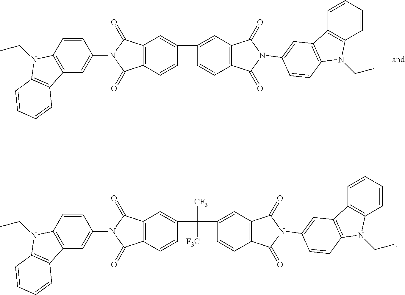
V. A. Skorodumov et al., Khimiya Geterotsiklicheskikh Soedinenii, Chemistry of Heterocyclic Compounds 3 (1967) 62-63 discloses thiazine-phthalimide derivatives of formulae IV and VIII:

Wang Yi et al., Dyes and Pigments 100 (2007) 87-96 disclose naphthalimide derivatives as an efficient guest/host fluorescent energy transfer pair and its application properties in heavily-doped red organic light-emitting diodes.

Journal of Chemical Research 3 (2008) 137-140 disclose naphthalimide derivatives as an efficient guest/host fluorescent energy transfer pair and its application properties in heavily-doped red organic light-emitting diodes.

D. Gudeika et al., Dyes and Pigments 114 (2015) 239-252 (available online: Nov. 21, 2014) report the synthesis of a series of 1,8-naphthalimide and carbazole derivatives. These compounds exhibit high thermal stability with 5% weight loss temperature up to 476° C. Most of the synthesized compounds are capable of glass formation with glass transition temperatures from 30 to 87° C. Naphthalimide and carbazole donor-acceptor systems show broad unstructured fluorescence spectra peaking at 460-580 nm. Singly bonded 3-C-monosubstituted and 3,6-C-disubstituted compounds show pronounced positive solvatochromic effects with the reduction of the non-radiative recombination rate in polar solvents which results in high photoluminescence quantum yields up to 0.83.
An object of the present invention is to provide a highly efficient and practically useful organic light-emitting element and an organic light-emitting material suitable for the organic light-emitting element. It has surprisingly been found that certain phthalimide and naphthalimide compounds emit delayed fluorescence and the use thereof in an organic light-emitting element provides a highly efficient organic EL element.
Accordingly, the present invention relates to compounds of formula

wherein
X is O, or NR2;
R1 is a C1-C25alkyl group, a C6-C10aryl group which is optionally substituted by one or more groups R8;
R2 is a C1-C6alkyl group, a C2-C4alkenyl group, or a C6-C10aryl group, which is optionally substituted by one or more groups R8; or
R1 and R2 together form a ring

wherein
R37, R38, R39 and R40 are independently of each other H, D, F, Cl, a C1-C25alkyl group, a C1-C25alkoxy group, a C6-C10aryl group which may optionally be substituted by one or more groups R8,
A1, A2 and A3 are C,
x is 0, or 1,
if x is 0,
A1 and A3 are connected via a double bond and together form a ring

if x is 1,
A1 and A2 and A2 and A3 are connected via a single bond and together form a ring system

R3, R4, R5, R6, R31, R32, R33, R34, R35 and R36 are independently of each other H, D, F, Cl, a C1-C25alkyl group, a C1-C25alkoxy group, a C6-C10aryl group which may optionally be substituted by one or more groups R8, or a donor group of formula

R8 is D, F, Cl, a C1-C12alkyl group, a C1-C12alkoxy group, or a C6-C10aryl group;
X1 is a direct bond, O, S, N(R15), C(═O), C(R16)(R17), B(R18), or Si(R19)(R20),
R10, R11, R21 and R21′ are independently of each other H, D, F, Cl, Br, or a C1-C25alkyl group;
R15, R16, R17, R18, R19 and R29 are independently of each other H, D, a C1-C25alkyl group, or a C6-C14aryl group, which can optionally be substituted by one, or more groups selected from a C1-C25alkyl group, a C1-C25alkoxy group and a C6-C10aryloxy group;
with the proviso that at least one of the groups R3, R4, R5, R6, R31, R32, R33, R34, R35 and R36 is a donor group of formula (Xa), or (Xd).
The present invention is also directed to the use of compounds of formula (I) for generating delayed fluorescence emission.
Thermally activated delayed fluorescence (TADF, E-type delayed fluorescence) is a promising way to obtain a high efficiency of exciton formation by converting spin-forbidden triplet excitons up to the singlet level by the mechanism of reverse intersystem crossing (RISC). In a TADF emitter, the upconversion mechanism uses the vibronic energy that, at sufficiently high temperatures 300 K), allows all of the excitons in an OLED to eventually produce light through singlet decay.
E-type delayed fluorescence fluorescence is defined herein as a process in which the first excited singlet state (S1) becomes populated by a thermally activated radiationless transition from the first excited triplet state (T1).
The present invention is also directed to an organic light-emitting element, comprising a compound of formula (I).
The organic light-emitting element offers an external quantum efficiency of more than 5%, especially more than 10% and reduced efficiency roll-off characteristics at high luminance.
The compound of formula (I) has preferably a difference between excited singlet energy and excited triplet energy ((ΔEST) of 0.5 eV or less, more preferably ΔEST of 0.35 eV or less, i.e. of 0.01 to 0.5 eV, especially 0.01 to 0.35 eV.
The determination of ΔEST can be carried either by quantum mechanical calculations (for example TD-DFT (time dependent density functional theory) calculations, for example with commercially available Gaussian 09 or ADF Amsterdam Density Functional software programs; for example as described in Adv. Mater. 2008, 20, 3325-3330), or experimentally.
Experimental Determination of ΔEST:
i) ΔEST can be determined based on the information given in the following formula:
Int(S 1 →S 0)/Int(T 1 →T 0)=k(S 1)/k(T 1)exp(−ΔE/k B T).
Int(S 1 →S 0)/Int(T 1 →T 0)=k(S 1)/k(T 1)exp(−ΔE/k B T).
The intensites Int(S1→S0) and Int(T1→T0) can be determined spectroscopically by a spectrophotometer. A graph of the logarithmic intensity ratios Int(S1→S0)/Int(T1→T0) measured at different temperatures versus the reciprocal of the absolute temperature T generally shows a straight line. The measurement is carried out in a temperature range from room temperature (300 K) to 77 K to 4.2 K (the temperature can be adjusted by means of a cryostat). The respective transitions (S1→S0) and (T1→T0) (band intensities) can be identified since the triplet transition is at lower energy than the singlet transition and increases in intensity with decreasing temperature. The measurements are usually performed in oxygen-free dilute solutions (about 10−2 molL−1) or thin films of the respective compounds or doped films comprising the corresponding compounds.
The slope of the straight line mentioned above is −ΔE/kBT. With kB=1.380 10−23 JK−1=0.695 cm−1 K−1, ΔEST can be determined.
ii) ΔEST can also be determined by measuring the temperature dependency of the emission decay as known by a person skilled in the art.
iii) An approximate estimation of ΔEST can be achieved by recording the fluorescence and phosphorescence spectra at low temperature (for example 77 K or 4.2 K using a cryostat). ΔEST then corresponds to an approximation of the energy difference between the high-energy rising edges of the fluorescence or phosphorescence band.
The compounds of formula (I) contain preferably one, or two donor groups of formula (Xa) and/or (Xd).
Among the compounds of formula (I) compounds of formula

wherein X, R1, R3, R4, R5 and R6 are as defined above, and compounds of formula

wherein X, R1, R31, R32, R33, R34, R35 and R36 are as defined above, are preferred.
Among the compounds of formula (II) compounds of formula

wherein R1, R3, R4, R5 and R6 are as defined above, and compounds of formula

wherein R3, R4, R5 and R6 are as defined above, are more preferred.
Compounds of formula

are even more preferred, wherein
R3, R4, R5 and R6 are independently of each other a donor group of formula (Xa), or (Xd); or
R3 and R6 are H and R4 and R5 are independently of each other a donor group of formula (Xa), or (Xd); or
R4 and R5 are H and R3 and R6 are independently of each other a donor group of formula (Xa), or (Xd); or
R4 and R6 are H and R3 and R5 are independently of each other a donor group of formula (Xa), or (Xd); or
R3, R4 and R6 are H and R5 is a donor group of formula (Xa), or (Xd); or
R3, R4 and R5 are H and R6 is a donor group of formula (Xa), or (Xd).
Compounds of formula

are even more preferred, wherein
R3, R4, R5 and R6 are independently of each other a donor group of formula (Xa), or (Xd); or
R3 and R6 are H and R4 and R5 are independently of each other a donor group of formula (Xa), or (Xd); or
R4 and R5 are H and R3 and R6 are independently of each other a donor group of formula (Xa), or (Xd); or
R3, R4 and R5 are H and R6 is a donor group of formula (Xa), or (Xd); or
R3, R4 and R6 are H and R5 is a donor group of formula (Xa), or (Xd); or
R3, R5 and R6 are H and R4 is a donor group of formula (Xa), or (Xd); or
R4, R5 and R6 are H and R3 is a donor group of formula (Xa), or (Xd).
Among the compounds of formula (III) compounds of formula

(IIIa), wherein R1, R31, R32, R33, R34, R35 and R36 are as defined above, and

wherein R31, R32, R33, R34, R35 and R36 are as defined above, are more preferred.
Compounds of formula

are even more preferred, wherein
R31, R32, R33, R35 and R36 are H and R34 is a donor group of formula (Xa), or (Xd); or
R31, R32, R33, R34 and R36 are H and R35 is a donor group of formula (Xa), or (Xd); or
R31, R32, R33, R34 and R35 are H and R36 is a donor group of formula (Xa), or (Xd); or
R31, R32, R35 and R36 are H and R33 and R34 are independently of each other a donor group of formula (Xa), or (Xd);
R32 and R35 are H and R31, R33, R34 and R36 are independently of each other a donor group of formula (Xa), or (Xd); or
R31, R32, R33, R34, R35 and R36 are independently of each other a donor group of formula (Xa), or (Xd).
Compounds of formula

are even more preferred, wherein
R31, R32, R33, R35 and R36 are H and R34 is a donor group of formula (Xa), or (Xd); or
R31, R32, R34, R35 and R36 are H and R33 is a donor group of formula (Xa), or (Xd); or
R31, R32, R35 and R36 are H and R33 and R34 are independently of each other a donor group of formula (Xa), or (Xd).
R1 is preferably a C1-C25alkyl group, a group of formula

wherein
R41 and R42 are a C1-C8alkyl group;
R43 is a C1-C8alkyl group, or a C1-C8alkoxy group;
R44 is a C1-C8alkyl group, or a phenyl group; and
R45 is a C1-C8alkyl group. More preferably, R1 is a group of formula

and R42 are a C1-C8alkyl group.
The donor group is preferably a donor group of formula (Xa), wherein X1 is a direct bond, O, S, C(CH3)(CH3), C(═O),
or a donor group of formula (Xd), wherein R21 and R21′ are H.
The donor group is more preferably a group of formula

especially

Examples of compounds of formula

are shown below:


Among compounds of formula (H) those are preferred which are substituted especially by donor groups of formula

such as, for example, compounds (A-1), (A-2), (A-3), (A-4), (A-5), (A-6), (A-10), (A-11), (A-12), (A-13), (A-14), (A-15), (A-19), (A-20), (A-21), (A-22), (A-23), (A-24), (A-28), (A-29), (A-30), (A-31), (A-32), (A-33), (A-37), (A-38), (A-39), (A-40), (A-41), (A-42), (A-46), (A-47), (A-48), (A-49), (A-50), (A-51), (A-55), (A-56), (A-57), (A-58), (A-59), (A-60), (A-64), (A-65), (A-66), (A-67), (A-68), (A-69), (A-73), (A-74), (A-75), (A-76), (A-77), (A-78), (A-82), (A-83), (A-84), (A-85), (A-86), (A-87), (A-92), (A-93) (A-94), (A-95), (A-96), (A-97), (A-99), and (A-100).
The most preferred examples are (A-1), (A-2), (A-3), (A-4), (A-6), (A-10), (A-11), (A-12), (A-13), (A-15), (A-19), (A-20), (A-21), (A-22), (A-24), (A-28), (A-29), (A-30), (A-31), (A-33), (A-37), (A-38), (A-39), (A-40), (A-42), (A-46), (A-47), (A-48), (A-49), (A-51), (A-55), (A-56), (A-57), (A-58), (A-60), (A-64), (A-65), (A-66), (A-67), (A-69), (A-73), (A-74), (A-75), (A-76), (A-78), (A-82), (A-83), (A-84), (A-85), (A-87), (A-92), (A-99), and (A-100).
Examples of compounds of formula

are shown below:


Among compounds of formula (III) those are preferred which are substituted especially by donor groups of formula

such as, for example, compounds (B-1), (B-2), (B-3), (B-4), (B-5), (B-6), (B-10), (B-11), (B-12), (B-13), (B-14), (B-15), (B-19), (B-20), (B-21), (B-22), (B-23), (B-24), (B-28), (B-29), (B-30), (B-31), (B-32), (B-33), (B-37), (B-38), (B-39), (B-40), (B-41), (B-42), (B-46), (B-47), (B-48), (B-49), (B-50), (B-51), (B-52), (B-53), (B-54), (B-55), (B-56), (B-57), (B-58), (B-59), (B-60), (B-61), (B-62), (B-63) and (B-64).
The most preferred examples are (B-1), (B-4), (B-6), (B-10), (B-13), (B-15), (B-19), (B-20), (B-21), (B-23), (B-24), (B-28), (B-29), (B-31), (B-33), (B-37), (B-38), (B-39), (B-40), (B-42), (B-52), (B-53), (B-55), (B-56), (B-57), (B-58), (B-59), (B-60), (B-61), (B-62), and (B-63).
C1-C25alkyl, C1-C18alkyl and C1-C12alkyl, respectively is typically linear or branched, where possible. Examples are methyl, ethyl, n-propyl, isopropyl, n-butyl, sec.-butyl, isobutyl, tert.-butyl, n-pentyl, 2-pentyl, 3-pentyl, 2,2-dimethylpropyl, 1,1,3,3-tetramethylpentyl, n-hexyl, 1-methylhexyl, 1,1,3,3,5,5-hexamethylhexyl, n-heptyl, isoheptyl, 1,1,3,3-tetramethylbutyl, 1-methylheptyl, 3-methylheptyl, n-octyl, 1,1,3,3-tetramethylbutyl and 2-ethylhexyl, n-nonyl, decyl, undecyl, dodecyl, tridecyl, tetradecyl, pentadecyl, hexadecyl, heptadecyl, or octadecyl. C1-C8alkyl is typically methyl, ethyl, n-propyl, isopropyl, n-butyl, sec.-butyl, isobutyl, tert.-butyl, n-pentyl, 2-pentyl, 3-pentyl, 2,2-dimethyl-propyl, n-hexyl, n-heptyl, n-octyl, 1,1,3,3-tetramethylbutyl and 2-ethylhexyl. C1-C6alkyl is typically methyl, ethyl, n-propyl, isopropyl, n-butyl, sec.-butyl, isobutyl, tert.-butyl, n-pentyl, 2-pentyl, 3-pentyl, 2,2-dimethylpropyl, 1,1,3,3-tetramethylpentyl and n-hexyl.
C2-C4alkenyl groups are straight-chain or branched alkenyl groups, such as e.g. vinyl, allyl, methallyl, isopropenyl, 2-butenyl and 3-butenyl.
C1-C25alkoxy groups, C1-C18alkoxy groups and C1-C12alkoxy groups, respectively are straight-chain or branched alkoxy groups, e.g. methoxy, ethoxy, n-propoxy, isopropoxy, n-butoxy, sec-butoxy, tert-butoxy, amyloxy, isoamyloxy or tert-amyloxy, heptyloxy, octyloxy, isooctyloxy, nonyloxy, decyloxy, undecyloxy, dodecyloxy, tetradecyloxy, pentadecyloxy, hexadecyloxy, heptadecyloxy and octadecyloxy. Examples of C1-C8alkoxy are methoxy, ethoxy, n-propoxy, isopropoxy, n-butoxy, sec.-butoxy, isobutoxy, tert.-butoxy, n-pentyloxy, 2-pentyloxy, 3-pentyloxy, 2,2-dimethylpropoxy, n-hexyloxy, n-heptyloxy, n-octyloxy, 1,1,3,3-tetramethylbutoxy and 2-ethylhexyloxy, preferably C1-C4alkoxy such as typically methoxy, ethoxy, n-propoxy, isopropoxy, n-butoxy, sec.-butoxy, isobutoxy, tert.-butoxy.
C6-C14aryl, especially C6-C10aryl, which optionally can be substituted, is typically phenyl, naphthyl, especially 1-naphthyl, or 2-naphthyl, or biphenylyl, which may be unsubstituted or substituted by one, or more C1-C8alkyl, C1-C8alkoxy and/or C6-C10aryloxy groups, especially C1-C8alkyl, C1-C8alkoxy groups.
C6-C10aryloxy, which optionally can be substituted by one, or more C1-C8alkyl and/or C1-C8alkoxy groups, is typically phenoxy, 1-naphthoxy, or 2-naphthoxy.
The present invention is directed to a light-emitting layer comprising the compound of the formula (I).
In addition, the present invention is directed to an organic light emitting element, comprising the compound of the formula (I).
For the compounds of formula (I) the preferences specified above apply.
Compounds of formula (II) and (III) are preferred. Compounds of formula (IIa), (IIb), (IIIa) and (IIIb) are more preferred. Among compounds of formula (IIa), (IIb), (IIIa) and (IIIb) compounds (A-1) to (A-100) and (B-1) to (B-64) are preferred, compounds (A-1), (A-2), (A-3), (A-4), (A-6), (A-10), (A-11), (A-12), (A-13), (A-15), (A-19), (A-20), (A-21), (A-22), (A-24), (A-28), (A-29), (A-30), (A-31), (A-33), (A-37), (A-38), (A-39), (A-40), (A-42), (A-46), (A-47), (A-48), (A-49), (A-51), (A-55), (A-56), (A-57), (A-58), (A-60), (A-64), (A-65), (A-66), (A-67), (A-69), (A-73), (A-74), (A-75), (A-76), (A-78), (A-82), (A-83), (A-84), (A-85), (A-87), (A-92), (A-99), (A-100), (B-1), (B-4), (B-6), (B-10), (B-13), (B-15), (B-19), (B-20), (B-21), (B-23), (B-24), (B-28), (B-29), (B-31), (B-33), (B-37), (B-38), (B-39), (B-40), (B-42), (B-52), (B-53), (B-55), (B-56), (B-57), (B-58), (B-59), (B-60), (B-61), (B-62) and (B-63) are most preferred.
The compounds of formula (I) can be used as host in combination with a fluorescent guest material in the emitting layer of an organic EL element. Known fluorescent materials are usable as the fluorescent guest material. Examples of the fluorescent guest material include a bisarylamino naphthalene derivative, an aryl-substituted naphthalene derivative, a bisarylamino anthracene derivative, an aryl-substituted anthracene derivative, a bisarylamino pyrene derivative, an aryl-substituted pyrene derivative, a bisarylamino chrysene derivative, an aryl-substituted chrysene derivative, a bisarylamino fluoranthene derivative, an aryl-substituted fluoranthene derivative, an indenoperylene derivative, a pyrromethene boron complex compound, a compound having a pyrromethene skeleton or a metal complex thereof, a diketopyrrolopyrrole derivative, and a perylene derivative. Examples are 2,5,8,11-tetra-tert-butylperylene (TBPe), 9,10-bis[N,N-di-(p-tolyl)-amino]anthracene (TTPA), 2,8-di-tert-butyl-5,11-bis(4-tert-butylphenyl)-6,12-diphenyltetracene (TBRb) and dibenzo{[f,f′]-4,4′,7,7′-tetraphenyl}diindeno[1,2,3-cd:1′,2′,3′-lm]perylene (DBP). In case of using the compound of formula (I) as host material, the content of the compound of formula (I) in the light-emitting layer falls within the range of 51 to 99 wt %, preferably 80 to 99 wt %.
Alternatively, the compounds of formula (I) can be used as guest in combination with a host material in the emitting layer of an organic EL element. In said embodiment the compound of formula (I), i.e. the organic light-emitting material, has preferably a difference between excited singlet energy and excited triplet energy ((ΔEST) of 0.5 eV or less, more preferably ΔEST of 0.35 eV or less, i.e. of 0.01 to 0.5 eV, especially 0.01 to 0.35 eV. The organic light-emitting material may be used alone in the light-emitting layer. However, as necessary, for the purpose of, for example, confining, in the organic light-emitting material, singlet excitons and triplet excitons generated in the organic light-emitting material, the organic light-emitting material of the present invention and an organic compound which has a higher value of at least any one of excited singlet energy and excited triplet energy than those of the organic light-emitting material and serves as a host material are preferably used in the light-emitting layer. At least any one of the excited singlet energy (S1h) and excited triplet energy (T1h) of the host compound is preferably higher by 0.1 eV or more, particularly preferably higher by 0.2 eV or more than the excited singlet energy (S1g) and excited triplet energy (T1g) of the organic light-emitting material of the present invention. That is, it is preferred that one or both of (S1h)−(S1g)>0.1 eV and (T1h)−(T1g)>0.1 eV be satisfied and it is more preferred that one or both of (S1h)−(S1g)>0.2 eV and (T1h)−(T1g)>0.2 eV be satisfied.
The organic EL element of the present invention has, as essential layers, an anode, a hole-transporting layer, a light-emitting layer, and a cathode.
Further, the organic EL element of the present invention may have, as layers other than the essential layers, an electron-transporting layer, an electron-injecting layer, an electron-blocking layer, a hole-blocking layer, and an exciton element layer. In addition, the hole-transporting layer may be a hole-injecting/transporting layer having a hole-injecting function and the electron-transporting layer may be an electron-injecting/transporting layer having an electron-injecting function.
The organic EL element of the present invention may comprise in this order: a substrate, an anode, a hole-injecting layer, a hole-transporting layer, a light-emitting layer, an electron-transporting layer and a cathode. Alternatively, the cathode, the electron-transporting layer, the light-emitting layer, the hole-transporting layer, and the anode may be laminated on the substrate in the stated order.
Substrate
The organic EL element of the present invention is preferably supported by a substrate. The substrate is not particularly limited and may be any substrate which is conventionally used in an organic EL element. For example, a substrate formed of glass, transparent plastic, quartz, or the like may be used.
Anode
Preferably used as the anode in the organic EL element is one using, as an electrode substance, any of a metal, an alloy, an electrically conductive compound, and a mixture thereof with a high work function (4 eV or more). Specific examples of such electrode substance include metals such as Au and conductive transparent materials such as Cul, indium tin oxide (ITO), SnO2, and ZnO. Further, a material capable of producing an amorphous transparent conductive film such as IDIXO (In2O3—ZnO) may be used. In the production of the anode, it is possible to form any of those electrode substances into a thin film by a method such as vapor deposition or sputtering, and then form a pattern having a desired shape by a photolithographic method. Alternatively, in the case of using a coatable substance such as an organic conductive compound, it is also possible to employ a wet film-forming method of a printing mode, a coating mode, or the like.
Cathode
Meanwhile, used as the cathode is one using, as an electrode substance, any of a metal (referred to as electron-injecting metal), an alloy, an electrically conductive compound, and a mixture thereof with a low work function (4 eV or less). Specific examples of such electrode substance include sodium, a sodium-potassium alloy, magnesium, lithium, a magnesium/copper mixture, a magnesium/silver mixture, a magnesium/aluminum mixture, a magnesium/indium mixture, an aluminum/aluminum oxide (Al2O3) mixture, indium, a lithium/aluminum mixture, and a rare earth metal. Of those, from the viewpoints of electron-injecting property and durability against oxidation and the like, a mixture of an electron-injecting metal and a second metal, which has a work function value higher than that of the electron-injecting metal and is a stable metal, such as a magnesium/silver mixture, a magnesium/aluminum mixture, a magnesium/indium mixture, an aluminum/aluminum oxide (Al2O3) mixture, a lithium/aluminum mixture, or aluminum is suitable. It should be noted that a case where any one of the anode and the cathode of the organic EL element is transparent or translucent in order to transmit emitted light is advantageous because light emission luminance is improved.
Light-Emitting Layer
The light-emitting layer is a layer which emits light after excitons have been generated through the recombination of holes and electrons injected respectively from an anode and a cathode. The light-emitting layer preferably includes an organic light-emitting material and a host material. As the organic light-emitting material, there may be used one kind or two or more kinds selected from the compounds of formula (I). In order that the organic EL element of the present invention exhibits high luminous efficiency, it is important to confine, in the organic light-emitting material, singlet excitons and triplet excitons generated in the organic light-emitting material. Accordingly, it is preferred to use the host material in addition to the organic light-emitting material in the light-emitting layer. As the host material, there may be used an organic compound having a higher value of at least any one of excited singlet energy and excited triplet energy than those of the organic light-emitting material of the present invention. This allows singlet excitons and triplet excitons generated in the organic light-emitting material of the present invention to be confined in the molecule of the organic light-emitting material of the present invention and allows the luminous efficiency to be exhibited sufficiently. In the organic EL element of the present invention, light is emitted from the organic light-emitting material of the present invention included in the light-emitting layer.
In case of using the host material, the content of the organic light-emitting material of the present invention in the light-emitting layer fall within the range of 1 to 50 wt %, preferably 1 to 20 wt %.
The host material in the light-emitting layer is preferably an organic compound which has a hole-transporting ability and/or an electron-transporting ability, prevents an emission wavelength from becoming longer, and has a high glass transition temperature.
The host material may be a polymer, for example poly(N-vinylcarbazole) or polysilane. The host material may, however, be a small molecule, for example 4,4′-N,N′-dicarbazolebiphenyl (CDP=CBP), 2,6-bis(N-carbazolyl)pyridincphenyl (mCP), 3,3-di(9H-carbazol-9-yl)biphenyl (mCBP),


or tertiary aromatic amines, for example tris(4-carbazoyl-9-ylphenyl)amine (TCTA).
Injecting Layer
The injecting layer refers to a layer to be provided between an electrode and an organic layer for the purposes of reducing a driving voltage and improving a light emission luminance. The injecting layer includes a hole-injecting layer and an electron-injecting layer, and may be provided between the anode and the light-emitting layer or the hole-transporting layer, and between the cathode and the light-emitting layer or the electron-transporting layer. The injecting layer may be provided as necessary.
Customarily used hole injection materials include α-NPD, CuPc, MTDATA, or dipyrazino[2,3-f:2′,3′-h]quinoxaline-2,3,6,7,10,11-hexacarbonitrile (HAT-CN). Polymeric hole-injection materials can be used such as poly(N-vinylcarbazole) (PVK), polythiophenes, polypyrrole, polyaniline, self-doping polymers, such as, for example, sulfonated poly(thiophene-3-[2[(2-methoxyethoxy)ethoxy]-2,5-diyl) (Plexcore® OC Conducting Inks commercially available from Plextronics), and copolymers such as poly(3,4-ethylenedioxythiophene)/poly(4-styrenesulfonate) also called PEDOT/PSS.
Lithium-comprising organometallic compounds such as 8-hydroxyquinolatolithium (Liq), CsF, NaF, KF, Cs2CO3 or LiF may be applied between the electron transport layer and the cathode as an electron injection layer in order to reduce the operating voltage.
Blocking Layer
The blocking layer is capable of blocking charges (electrons or holes) and/or excitons present in the light-emitting layer from diffusing to the outside of the light-emitting layer. The electron-blocking layer may be arranged between the light-emitting layer and the hole-transporting layer, and blocks electrons from passing through the light-emitting layer toward the hole-transporting layer. Similarly, the hole-blocking layer may be arranged between the light-emitting layer and the electron-transporting layer, and blocks holes from passing through the light-emitting layer toward the electron-transporting layer. The blocking layer may also be used for blocking excitons from diffusing to the outside of the light-emitting layer. That is, the electron-blocking layer and the hole-blocking layer may each have a function of an exciton-blocking layer as well. The electron-blocking layer or exciton-blocking layer as used herein is meant to include a layer having a function of an electron-blocking layer and an exciton-blocking layer in one layer.
Hole-Blocking Layer
The hole-blocking layer has a function of the electron-transporting layer in a broad sense. The hole-blocking layer has a role in blocking holes from reaching the electron-transporting layer while transporting electrons. This can improve the probability of recombination of electrons and holes in the light-emitting layer. As a material for the hole-blocking layer, a material for the electron-transporting layer to be described below may be used as necessary.
Electron-Blocking Layer
The electron-blocking layer has a function of transporting holes in a broad sense. The electron-blocking layer has a role in blocking electrons from reaching the hole-transporting layer while transporting holes. This can improve the probability of recombination of electrons and holes in the light-emitting layer.
Exciton-Blocking Layer
The exciton-blocking layer refers to a layer for blocking excitons, which are generated by the recombination of holes and electrons in the light-emitting layer, from diffusing to a charge-transporting layer. The insertion of this layer allows excitons to be efficiently confined in the light-emitting layer, which can improve the luminous efficiency of an element. The exciton-blocking layer may be inserted on any of the anode side and the cathode side of the adjacent light-emitting layer, and may be simultaneously inserted on both of the sides. That is, when the exciton-blocking layer is provided on the anode side, the layer may be inserted between the hole-transporting layer and the light-emitting layer so as to be adjacent to the light-emitting layer. When the exciton-blocking layer is inserted on the cathode side, the layer may be inserted between the light-emitting layer and the cathode so as to be adjacent to the light-emitting layer. Further, the hole-injecting layer, the electron-blocking layer, and the like may be provided between the anode and the exciton-blocking layer adjacent to the anode side of the light-emitting layer, and the electron-injecting layer, the electron-transporting layer, the hole-blocking layer, and the like may be provided between the cathode and the exciton-blocking layer adjacent to the cathode side of the light-emitting layer. In the case of providing the blocking layer, it is preferred that at least any one of the excited singlet energy and excited triplet energy of a material to be used as the blocking layer be higher than the excited singlet energy and excited triplet energy of a light-emitting material.
Hole blocker materials typically used are 2,6-bis(N-carbazolyl)pyridine (mCPy), 2,9-dimethyl-4,7-diphenyl-1,10-phenanthroline (bathocuproin, (BCP)), bis(2-methyl-8-quinolinato)-4-phenylphenylato)aluminum(III) (BAlq), phenothiazine S,S-dioxide derivates and 1,3,5-tris(N-phenyl-2-benzylimidazolyl)benzene) (TPBI), TPBI also being suitable as electron-transport material. Further suitable hole blockers and/or electron conductor materials are 2,2′,2″-(1,3,5-benzenetriyl)tris(1-phenyl-1-H-benzimidazole), 2-(4-biphenylyl)-5-(4-tert-butylphenyl)-1,3,4-oxadiazole, 8-hydroxyquinolinolatolithium, 4-(naphthalen-1-yl)-3,5-diphenyl-4H-1,2,4-triazole, 1,3-bis[2-(2,2′-bipyridin-6-yl)-1,3,4-oxadiazo-5-yl]benzene, 4,7-diphenyl-1,10-phenanthroline, 3-(4-biphenylyl)-4-phenyl-5-tert-butylphenyl-1,2,4-triazole, 6,6′-bis[5-(biphenyl-4-yl)-1,3,4-oxadiazo-2-yl]-2,2′-bipyridyl, 2-phenyl-9,10-di(naphthalene-2-yl)anthracene, 2,7-bis[2-(2,2′-bipyridin-6-yl)-1,3,4-oxadiazo-5-yl]-9,9-dimethylfluorene, 1,3-bis[2-(4-tert-butylphenyl)-1,3,4-oxadiazo-5-yl]benzene, 2-(naphthalene-2-yl)-4,7-diphenyl-1,10-phenanthroline, tris(2,4,6-trimethyl-3-(pyridin-3-yl)phenyl)borane, 2,9-bis(naphthalene-2-yl)-4,7-diphenyl-1,10-phenanthroline, 1-methyl-2-(4-(naphthalene-2-yl)phenyl)-1H-imidazo[4,5-f][1,10]phenanthroline,

and 2,4,6-tris(biphenyl-3-yl)-1,3,5-triazine (T2T).
Hole-Transporting Layer
The hole-transporting layer is formed of a hole-transporting material having a function of transporting holes. The hole-transporting layer may be provided in a single layer or a plurality of layers.
The hole-transporting material has any of hole-injecting or -transporting property and electron-blocking property, and may be an organic material or an inorganic material. An applicable known hole-transporting material is exemplified by a triazole derivative, an oxadiazole derivative, an imidazole derivative, a carbazole derivative, an indolocarbazole derivative, a polyarylalkane derivative, a pyrazoline derivative, a pyrazolone derivative, a phenylenediamine derivative, an arylamine derivative, an amino-substituted chalcone derivative, an oxazole derivative, a styrylanthracene derivative, a fluorenone derivative, a hydrazone derivative, a stilbene derivative, a silazane derivative, an aniline-based copolymer, or a conducting polymeric oligomer, particularly a thiophene oligomer. However, preferably used are a porphyrin compound, an aromatic tertiary amine compound, and a styrylamine compound, and more preferably used is an aromatic tertiary amine compound. Customarily used hole-transporting molecules are selected from the group consisting of

(4-phenyl-N-(4-phenylphenyl)-N-[4-[4-(N-[4-(4-phenyl-phenyl)phenyl]anilino)phenyl]phenyl]aniline),

(4-phenyl-N-(4-phenylphenyl)-N-[4-[4-(4-phenyl-N-(4-phenylphenyl)anilino)phenyl]phenyl]aniline),

(4-phenyl-N-[4-(9-phenylcarbazol-3-yl)phenyl]-N-(4-phenylphenyl)aniline)

(1,1′,3,3′-tetraphenylspiro[1,3,2-benzodiazasilole-2,2′-3a,7a-dihydro-1,3,2-benzodiazasilole]),

(N2,N2,N2′,N2′,N7,N7,N7′,N7′-octakis(p-tolyl)-9,9′-spirobi[fluorene]-2,2′,7,7′-tetramine), 4,4′-bis[N-(1-naphthyl)-N-phenylamino]biphenyl (α-NPD), N,N′-diphenyl-N,N′-bis(3-methylphenyl)-[1,1′-biphenyl]-4,4′-diamine (TPD), 1,1-bis[(di-4-tolylamino)phenyl]-cyclohexane (TAPC), N,N′-bis(4-methylphenyl)-N,N′-bis(4-ethylphenyl)-[1,1′-(3,3′-dimethyl)-biphenyl]-4,4′-diamine (ETPD), tetrakis(3-methylphenyl)-N,N,N′,N′-2,5-phenylenediamine (PDA), α-phenyl-4-N,N-diphenylaminostyrene (TPS), p-(diethylamino)benzaldehyde diphenylhydrazone (DEH), triphenylamine (TPA), bis[4-(N,N-diethylamino)2-methylphenyl](4-methylphenyl)methane (MPMP), 1-phenyl-3-[p-(diethylamino)styryl]5-[p-(diethylamino)phenyl]pyrazoline (PPR or DEASP), 1,2-trans-bis(9H-carbazol9-yl)-cyclobutane (DCZB), N,N,N′,N′-tetrakis(4-methylphenyl)-(1,1′-biphenyl)-4,4′-diamine (TTB), fluorine compounds such as 2,2′,7,7′-tetra(N,N-di-tolyl)amino9,9-spirobifluorene (spiro-TTB), N,N′-bis(naphthalen-1-yl)-N,N′-bis(phenyl)9,9-spirobifluorene (spiro-NPB) and 9,9-bis(4-(N,N-bis-biphenyl-4-yl-amino)phenyl-9Hfluorene, benzidine compounds such as N,N′-bis(naphthalen-1-yl)-N,N′-bis(phenyl)benzidine and porphyrin compounds such as copper phthalocyanines,

and CzSi. In addition, polymeric hole-injection materials can be used such as poly(N-vinylcarbazole) (PVK), polythiophenes, polypyrrole, polyaniline, self-doping polymers, such as, for example, sulfonated poly(thiophene-3-[2[(2-methoxyethoxy)ethoxy]-2,5-diyl) (Plexcore® OC Conducting Inks commercially available from Plextronics), and copolymers such as poly(3,4-ethylenedioxythiophene)/poly(4-styrenesulfonate) also called PEDOT/PSS.
Electron-Transporting Layer
The electron-transporting layer is formed of a material having a function of transporting electrons. The electron-transporting layer may be provided in a single layer or a plurality of layers.
An electron-transporting material (may also serve as a hole-blocking material) has only to have a function of transporting electrons, which are injected from the cathode, to the light-emitting layer. An applicable electron-transporting layer is exemplified by a nitro-substituted fluorene derivative, a diphenylquinone derivative, a thiopyran dioxide derivative, car-bodiimide, a fluorenylidenemethane derivative, an anthraquinodimethane derivative, an anthrone derivative, or an oxadiazole derivative. In addition, in oxadiazole derivative, a thiadiazole derivative in which an oxygen atom of an oxadiazole ring is substituted by a sulfur atom, or a quinoxaline derivative having a quinoxaline ring known as an electron-withdrawing group may also be used as the electron-transporting material. In addition, a polymer material obtained by introducing any of those materials into a polymer chain, or a polymer material including any of those materials in a polymer main chain may also be used. Suitable electron-transporting materials comprise 1,3,5-tris(N-phenyl-2-benzylimidazolyl)benzene (TPBi),

metals chelated with oxinoid compounds, such as tris(8-hydroxyquinolato)aluminum (Alq3), compounds based on phenanthroline such as 2,9-dimethyl-4,7-diphenyl-1,10-phenanthroline (DDPA=BCP), 4,7-diphenyl-1,10-phenanthroline (Bphen), 2,4,7,9-tetraphenyl-1,10-phenanthroline, 4,7-diphenyl-1,10-phenanthroline (DPA) or phenanthroline derivatives disclosed in EP1786050, in EP1970371, or in EP1097981, and azole compounds such as 2-(4-biphenylyl)-5-(4-t-butylphenyl)-1,3,4-oxadiazole (PBD) and 3-(4-biphenylyl)-4phenyl-5-(4-t-butylphenyl)-1,2,4-triazole (TAZ).
Examples of possible element structures are shown below:
ITO (100 nm)/α-NPD (35 nm)/CBP: 6% by weight cpd. of formula (I) (15 nm)/TPBi (65 nm)/LiF (0.8 nm)/Al (80 nm)
ITO (100 nm)/α-NPD (40 nm)/mCP/PPT: 6% by weight cpd. of formula (I) (20 nm)/PPT (40 nm)/LiF (0.8 nm)/Al (80 nm)
ITO (30-100 nm)/α-NPD (60 nm)/mCP: 6% by weight cpd. of formula (I) (20 nm)/Bphen (40 nm)/MgAg (100 nm)/Ag (20 nm)
ITO (30-100 nm)/α-NPD (60 nm)/PYD2: 6% by weight cpd. of formula (I) (20 nm)/Bphen (40 nm)/MgAg (100 nm)/Al (20 nm)
ITO/α-NPD (35 nm)/6% by weight cpd. of formula (I): CBP (15 nm)/TPBi (65 nm)/LiF (0.8 nm)/Al (80 nm)
ITO (100 nm)/HAT-CN (10 nm)/Tris-PCz (30 nm)/CBP: 3, 6, 10, or 15% by weight cpd. of formula (I) (30 nm)/BPY-TP2 (40 nm)/LiF (0.8 nm)/Al (100 nm)
ITO (100 nm)/α-NPD (35 nm)/CBP (10 nm)/DPEPO: 6 to 12% by weight cpd. of formula (I) (15 nm)/DPEPO (10 nm)/TPBi (65 nm)/LiF (0.5 nm)/Al (80 nm)]
ITO (100 nm)/HAT-CN (10 nm)/Tris-PCz (30 nm)/mCBP: 6 to 12% by weight cpd. of formula (I) (30 nm)/T2T (10 nm)/Bpy-TP2 (40 nm)/LiF (0.8 nm)/Al (100 nm)
ITO (100 nm)/α-NPD (30 nm)/TCTA (20 nm)/CzSi (10 nm)/DPEPO: 6 to 12% by weight cpd. of formula (I) (20 nm)/DPEPO (10 nm)/TPBi (30 nm)/LiF (0.8 nm)/Al (100 nm)
ITO: indium/tin oxide; α-NPD: 4,4′-bis[N-(1-naphthyl)-N-phenylamino]biphenyl; CBP: 4,4′-N,N′-dicarbazolebiphenyl; TPBi: 1,3,5-tris(N-phenyl-2-benzylimidazolyl)benzene; mCP: 2,6-bis(N-carbazolyl)pyridine; PPT:

Bphen: 4,7-diphenyl-1,10-phenanthroline; PYD2:

HAT-CN: dipyrazino[2,3-f:2′,3′-h]quinoxaline-2,3,6,7,10,11-hexacarbonitrile; Tris-PCz:

BPY-TP2:

DPE-PO:

The organic EL element emits light when an electric field is applied between an anode and a cathode of the resultant element.
The organic EL element of the present invention may be applied to any of a single element, an element formed of a structure with arrangement in an array fashion, and a structure in which an anode and a cathode are arranged in an X-Y matrix fashion.
According to the present invention, there is provided an element having significantly improved luminous efficiency as compared to a conventional element using light emission from a singlet state by incorporating the organic light-emitting material having a specific skeleton of the present invention into the light-emitting layer which emits delayed fluorescence. The element can exhibit excellent performance when being applied to a full-color or multi-color panel. The element may also be utilized in a backlight, lighting, and the like.
The above compounds of formula (I) can be used in electrophotographic photoreceptors, photoelectric converters, sensors, dye lasers, solar cell devices and organic light emitting elements.
The compounds of the present invention can be synthesized using copper catalyzed Ullmann conditions or palladium catalyzed Buchwald-Hartwig conditions. Suitable phthalimide and naphthalimide base skeletons are either commercially available, or can be obtained by processes known to those skilled in the art. Reference is made to Organic Letters, 13(20) (2011) 5532-5535, WO2007120788A1, H.-Y. Wang et al., Spectrochimica Acta Part A 93 (2012) 343-347, Georgi H. Dobrikov et al., Cent. Eur. J. Chem. 9(6) (2011) 1126-1132, S. Wang et al., Synthetic Metals 150 (2005) 33-38 and Yi Wang et al., Dyes and Pigments 86 (2010) 190-196.
The following examples are included for illustrative purposes only and do not limit the scope of the claims. Unless otherwise stated, all parts and percentages are by weight.

a) The compound 1a is prepared from 4-bromo-1,8-naphthalenedicarboxylic acid anhydride and 2,6-diisopropylaniline according to the synthetic procedure described in Organic Letters, 13(20) (2011) 5532-5535.

b) The product from example 1a (2.29 mmol), dimethylacridine (2.29 mmol), tris(dibenzylideneacetone) dipalladium (0.046 mmol), tri-tert-buthylphosphine (0.092 mmol), sodium t-buthoxide (3.44 mmol) and 12.5 ml of toluene are placed in a 50 ml flask. The mixture is stirred at 110° C. overnight and cooled. The mixture is washed with H2O and sat. NaClaq, then the aqueous layer is extracted with ethyl acetate. The combined organic layer is dried over MgSO4 subsequently concentrated under reduced pressure. A orange solid, compound (B-4), is obtained by washing with hexane and drying in vacuum. (Yield: 80.5%). The product is subsequently purified using zone sublimation. 1H-NMR (ppm, CDCl3): 8.86 (d, 1H), 8.68 (d, 1H), 8.12 (d, 1H), 7.84 (d, 1H), 7.68 (td, 1H), 7.55 (dd, 2H), 7.49 (d, 1H), 7.36 (d, 2H), 6.97 (td, 2H), 6.90 (td, 2H), 6.04 (dd, 2H), 2.83 (m, 2H), 1.85 (s, 3H), 1.80 (s, 3H), 1.2 (t, 12H).

The compound B-1 is prepared according to the method described in Example 1 using carbazole in place of dimethylacridine.
1H-NMR (ppm, CDCl3): 8.86 (d, 1H), 8.73 (d, 1H), 8.24 (d, 2H), 7.97 (d, 1H), 7.88 (d, 1H), 7.68 (t, 1H), 7.51 (t, 1H), 7.38 (m, 6H), 7.11 (d, 2H), 2.83 (m, 2H), 1.21 (t, 12H).

The compound B-13 is prepared according to the method described in Example 1 using 3-bromo-7H-benzimidazo[2,1-a]benz[de]isoquinoline-7-one in place of the compound 1a.
1H-NMR (ppm, CDCl3): 9.08 (d, 1H), 8.86 (d, 1H), 8.61 (m, 1H), 8.14 (d, 1H), 7.94 (m, 1H), 7.86 (d, 1H), 7.72 (t, 1H), 7.54 (m, 4H), 6.96 (t, 2H), 6.88 (t, 2H), 6.03 (d, 2H), 1.87 (s, 3H), 1.78 (s, 3H).
a) Photoluminescent Characterization in Neat Film
On a silicon substrate, compound

is vacuum-deposited in a thickness of 50 nm. Absorption, fluorescent spectra (excitation at 354 nm) and photoelectron yield spectroscopy of the film are measured, subsequently HOMO and LUMO (eV) of the compound are estimated as 6.14 eV and 3.90 eV, respectively.
b) Photoluminescent Characterization in Host-Guest Film
On a silicon substrate, mCBP doped with 9.8 w % of compound (B-4) is co-deposited in a thickness of 60 nm. The time-resolved and temperature-dependent emission spectra of the host-guest film are measured by photoluminescence spectroscopy with a streak camera. The prompt (0-15 ns) and delayed (0.1-2 ms) fluorescent components and the temperature dependency are observed as shown Table 1. The host-guest film shows an emission peak at 601 nm in PL spectrum.
| TABLE 1 |
| Temperature dependence of PL emission of co-deposited film (mCBP |
| doped with 9.8 w % of compound (B-4)) (streak camera) |
| Temperature | ||
| (K.) | Prompt PL intensity (a.u.) | Delayed PL intensity (a.u.) |
| 8 | 0.875 | 0.060 |
| 68 | 0.833 | 0.256 |
| 139 | 0.875 | 0.720 |
| 199 | 0.938 | 0.970 |
| 249 | 0.917 | 1 |
| 279 | 1 | 0.976 |
| 298 | 0.958 | 0.958 |
These results indicate that compound (B-4) is a TADF material.
An organic light emitting device (OLED) is fabricated by vacuum deposition of ITO (100 nm)/dipyrazino[2,3-f:2′,3′-h]quinoxaline-2,3,6,7,10,11-hexacarbonitrile (HAT-CN) (10 nm)/

(Tris-PCz, 30 nm)/89.3 w % 3,3-di(9H-carbazol-9-yl)biphenyl (mCBP):10.7 w % compound B-4 (30 nm)/2,4,6-tris(biphenyl-3-yl)-1,3,5-triazine (T2T, 10 nm)/

(Bpy-TP2, 40 nm)/LiF (0.8 nm)/Al (100 nm) on a glass substrate, subsequently the device is encapsulated and the performance of the device is evaluated. The device shows an emission peak at 616 nm in elec-troluminescence (EL) spectrum with an external quantum efficiency (EQE) of 7.5%.
Claims (21)
1. A compound of formula

wherein
X is O, or NR2;
R1 is a C1-C25alkyl group, a C6-C10aryl group which is optionally substituted by one or more groups R8;
R2 is a C1-C6alkyl group, a C2-C4alkenyl group, or a C6-C10aryl group, which is optionally substituted by one or more groups R8; or
R1 and R2 together form a ring

wherein
R37, R38, R39 and R40 are independently of each other H, D, F, Cl, a C1-C25alkyl group, a C1-C25alkoxy group, a C6-C10aryl group which may optionally be substituted by one or more groups R8,
A1, A2 and A3 are C,
x is 0, or 1,
if x is 0,
A1 and A3 are connected via a double bond and together form a ring

if x is 1, then X is NR2,
A1 and A2 and A2 and A3 are connected via a single bond and together form a ring system

R3, R4, R5, R6, R31, R32, R33, R34, R35 and R36 are independently of each other H, D, F, Cl, a C1-C25alkyl group, a C1-C25alkoxy group, a C6-C10aryl group which may optionally be substituted by one or more groups R8, or a donor group of formula

R8 is D, F, Cl, a C1-C12alkyl group, a C1-C12alkoxy group, or a C6-C10aryl group;
X1 is a direct bond, O, S, N(R15), C(═O), C(R16)(R17), B(R18), or Si(R19)(R20),
R10, R11, R21 and R21′ are independently of each other H, D, F, Cl, Br, or a C1-C25alkyl group;
R15, R16, R17, R18, R19 and R20 are independently of each other H, D, a C1-C25alkyl group, or a C6-C14aryl group, which can optionally be substituted by one, or more groups selected from a C1-C25alkyl group, a C1-C25alkoxy group and a C6-C10aryloxy group;
with the proviso that at least one of the groups R3, R4, R5, R6, R31, R32, R33, R34, R35 and R36 is a donor group of formula (Xa), or (Xd).
2. The compound according to claim 1 , which is a compound of formula

wherein X, R1, R3, R4, R5 and R6 are as defined in claim 1 .
3. The compound according to claim 2 , which is a compound of formula

wherein R1, R3, R4, R5 and R6 are as defined in claim 1 .
4. The compound according to claim 1 , wherein
R3, R4, R5 and R6 are independently of each other a donor group of formula (Xa), or (Xd) as defined in claim 1 ; or
R3 and R6 are H and R4 and R5 are independently of each other a donor group of formula (Xa), or (Xd) as defined in claim 1 ; or
R4 and R5 are H and R3 and R6 are independently of each other a donor group of formula (Xa), or (Xd) as defined in claim 1 ; or
R4 and R6 are H and R3 and R5 are independently of each other a donor group of formula (Xa), or (Xd) as defined in claim 1 ; or
R3, R4 and R6 are H and R5 is a donor group of formula (Xa), or (Xd) as defined in claim 1 ; or
R3, R4 and R5 are H and R6 is a donor group of formula (Xa), or (Xd) as defined in claim 1 .
5. The compound according to claim 2 , which is a compound of formula

wherein R3, R4, R5 and R6 are as defined in claim 1 .
6. The compound according to claim 5 , wherein
R3, R4, R5 and R6 are independently of each other a donor group of formula (Xa), or (Xd) as defined in claim 1 ; or
R3 and R6 are H and R4 and R5 are independently of each other a donor group of formula (Xa), or (Xd) as defined in claim 1 ; or
R4 and R5 are H and R3 and R6 are independently of each other a donor group of formula (Xa), or (Xd) as defined in claim 1 ; or
R3, R4 and R5 are H and R6 is a donor group of formula (Xa), or (Xd) as defined in claim 1 ; or
R3, R4 and R6 are H and R5 is a donor group of formula (Xa), or (Xd) as defined in claim 1 ; or
R3, R5 and R6 are H and R4 is a donor group of formula (Xa), or (Xd) as defined in claim 1 ; or
R4, R5 and R6 are H and R3 is a donor group of formula (Xa), or (Xd) as defined in claim 1 .
7. The compound according to claim 1 , which is a compound of formula

wherein X, R1, R31, R32, R33, R34, R35 and R36 are as defined in claim 1 .
8. The compound according to claim 7 , which is a compound of formula

wherein R31, R32, R33, R34, R35 and R36 are as defined in claim 1 .
9. The compound according to claim 8 , wherein
R31, R32, R33, R35 and R36 are H and R34 is a donor group of formula (Xa), or (Xd) as defined in claim 1 ; or
R31, R32, R34, R35 and R36 are H and R33 is a donor group of formula (Xa), or (Xd) as defined in claim 1 ; or
R31, R32, R35 and R36 are H and R33 and R34 are independently of each other a donor group of formula (Xa), or (Xd) as defined in claim 1 .
10. The compound according to claim 1 , wherein R1 is a C1-C25alkyl group, a group of formula

wherein
R41 and R42 are a C1-C8alkyl group;
R43 is a C1-C8alkyl group, or a C1-C8alkoxy group;
R44 is a C1-C8alkyl group, or a phenyl group; and
R45 is a C1-C8alkyl group.
11. The compound according claim 1 , wherein the donor group is a donor group of formula (Xa), wherein X1 is a direct bond, O, S, C(CH3)(CH3), C(═O), or
and R10 and R11 are as defined in claim 1 ; or a donor group of formula (Xd), wherein R21 and R21′ are H.
12. The compound according to claim 1 , wherein the donor group is a group of formula

13. A light-emitting layer comprising the compound according claim 1 .
14. An organic light emitting element, comprising the compound according to claim 1 .
15. The organic light-emitting element according to claim 14 , comprising a light-emitting layer comprising a compound according to claim 1 as guest and a host material.
16. The organic light-emitting element according to claim 14 , comprising a light-emitting layer comprising a compound according to claim 1 as host and a guest material.
17. The organic light-emitting element according to claim 14 , characterized in that it emits delayed fluorescence.
18. A device selected from the group consisting of a electrophotographic photoreceptor, photoelectric converter, sensor, dye laser, solar cell device and organic light emitting element, wherein the device comprises a compound according to claim 1 .
19. The compound according to claim 1 , wherein the compound is capable of generating delayed fluorescence emission.
20. A compound of formula

wherein
X is O, or NR2;
R1 is a C1-C25alkyl group, a group of formula

R2 is a C1-C6alkyl group, a C2-C4alkenyl group, or a C6-C10aryl group, which is optionally substituted by one or more groups R8; or
R1 and R2 together form a ring

wherein
R37, R38, R39 and R40 are independently of each other H, D, F, Cl, a C1-C25alkyl group, a C1-C25alkoxy group, a C6-C10aryl group which may optionally be substituted by one or more groups R8,
A1, A2 and A3 are C,
x is 0, or 1,
if x is 0,
A1 and A3 are connected via a double bond and together form a ring

if x is 1,
A1 and A2 and A2 and A3 are connected via a single bond and together form a ring system

R3, R4, R5, R6, R31, R32, R33, R34, R35 and R36 are independently of each other H, D, F, Cl, a C1-C25alkyl group, a C1-C25alkoxy group, a C6-C10aryl group which may optionally be substituted by one or more groups R8, or a donor group of formula

R8 is D, F, Cl, a C1-C12alkyl group, a C1-C12alkoxy group, or a C6-C10aryl group;
X1 is a direct bond, O, S, N(R15), C(═O), C(R16)(R17), B(R18), or Si(R19)(R20),
R10, R11, R21 and R21′ are independently of each other H, D, F, Cl, Br, or a C1-C25alkyl group;
R15, R16, R17, R18, R19 and R20 are independently of each other H, D, a C1-C25alkyl group, or a C6-C14aryl group, which can optionally be substituted by one, or more groups selected from a C1-C25alkyl group, a C1-C25alkoxy group and a C6-C10aryloxy group;
R41 and R42 are a C1-C8alkyl group;
R43 is a C1-C8alkoxy group;
R44 is a C1-C8alkyl group, or a phenyl group;
R45 is a C1-C8alkyl group; and
wherein at least one of the groups R3, R4, R5, R6, R31, R32, R33, R34, R35 and R36 is a donor group of formula (Xa), or (Xd).
21. A device selected from the group consisting of a electrophotographic photoreceptor, photoelectric converter, sensor, dye laser, solar cell device and organic light emitting element, wherein the device comprises a compound according to claim 20 .
Applications Claiming Priority (4)
| Application Number | Priority Date | Filing Date | Title |
|---|---|---|---|
| EP14185760 | 2014-09-22 | ||
| EP14185760 | 2014-09-22 | ||
| EP14185760.7 | 2014-09-22 | ||
| PCT/EP2015/071164 WO2016046034A1 (en) | 2014-09-22 | 2015-09-16 | Fluorescent organic light emitting elements having high efficiency |
Publications (2)
| Publication Number | Publication Date |
|---|---|
| US20170263868A1 US20170263868A1 (en) | 2017-09-14 |
| US10074805B2 true US10074805B2 (en) | 2018-09-11 |
Family
ID=51690802
Family Applications (1)
| Application Number | Title | Priority Date | Filing Date |
|---|---|---|---|
| US15/500,853 Active US10074805B2 (en) | 2014-09-22 | 2015-09-16 | Fluorescent organic light emitting elements having high efficiency |
Country Status (3)
| Country | Link |
|---|---|
| US (1) | US10074805B2 (en) |
| KR (1) | KR102397222B1 (en) |
| WO (1) | WO2016046034A1 (en) |
Families Citing this family (29)
| Publication number | Priority date | Publication date | Assignee | Title |
|---|---|---|---|---|
| CN109521397B (en) | 2013-06-13 | 2023-03-28 | 巴斯夫欧洲公司 | Detector for optically detecting at least one object |
| US11041718B2 (en) | 2014-07-08 | 2021-06-22 | Basf Se | Detector for determining a position of at least one object |
| CN107003785B (en) | 2014-12-09 | 2020-09-22 | 巴斯夫欧洲公司 | Optical detector |
| WO2016120392A1 (en) | 2015-01-30 | 2016-08-04 | Trinamix Gmbh | Detector for an optical detection of at least one object |
| KR102644439B1 (en) | 2015-07-17 | 2024-03-07 | 트리나미엑스 게엠베하 | Detector for optically detecting one or more objects |
| KR102545509B1 (en) * | 2016-06-02 | 2023-06-21 | 삼성디스플레이 주식회사 | Polycyclic compound and organic electroluminescence device including the same |
| CN106118125B (en) * | 2016-06-27 | 2017-10-10 | 苏州大学 | A kind of naphthalimide derivative, preparation method and application are in preparing fluorescent polyacrylonitrile |
| WO2018019921A1 (en) | 2016-07-29 | 2018-02-01 | Trinamix Gmbh | Optical sensor and detector for optical detection |
| EP3279194A1 (en) * | 2016-08-04 | 2018-02-07 | Cynora Gmbh | Organic molecules for use in organic optoelectronic devices |
| JP2019532517A (en) | 2016-10-25 | 2019-11-07 | トリナミクス ゲゼルシャフト ミット ベシュレンクテル ハフツング | Photodetector for optical detection |
| CN109891265B (en) | 2016-10-25 | 2023-12-01 | 特里纳米克斯股份有限公司 | Detector for optically detecting at least one object |
| US11860292B2 (en) | 2016-11-17 | 2024-01-02 | Trinamix Gmbh | Detector and methods for authenticating at least one object |
| KR102484739B1 (en) | 2016-11-17 | 2023-01-05 | 트리나미엑스 게엠베하 | Detector for optically detecting at least one object |
| CN108409716A (en) * | 2017-02-10 | 2018-08-17 | 三星显示有限公司 | Heterocyclic compound and organic light emitting apparatus including the heterocyclic compound |
| KR102654920B1 (en) * | 2017-02-10 | 2024-04-08 | 삼성디스플레이 주식회사 | Heterocyclic compound and organic light emitting device comprising the same |
| JP2020510820A (en) | 2017-03-16 | 2020-04-09 | トリナミクス ゲゼルシャフト ミット ベシュレンクテル ハフツング | Detector for optically detecting at least one object |
| CN106966954A (en) * | 2017-04-14 | 2017-07-21 | 中国科学院化学研究所 | A kind of hot activation delayed fluorescence material and organic electroluminescence device |
| KR20200040780A (en) | 2017-08-28 | 2020-04-20 | 트리나미엑스 게엠베하 | A detector that determines the position of at least one object |
| KR20200040782A (en) | 2017-08-28 | 2020-04-20 | 트리나미엑스 게엠베하 | Rangefinder for determining at least one geometric information |
| CN107573323B (en) * | 2017-10-16 | 2020-07-10 | 武汉大学 | Thermally induced delayed fluorescent material and preparation and application thereof |
| KR102405134B1 (en) * | 2017-10-31 | 2022-06-08 | 삼성디스플레이 주식회사 | Nitrogen contaiing compound and organic electroluminescence device including the same |
| KR20200128727A (en) * | 2018-03-09 | 2020-11-16 | 메르크 파텐트 게엠베하 | Compound for electronic device |
| KR20200068396A (en) | 2018-12-05 | 2020-06-15 | 솔브레인 주식회사 | Aromatic polycyclic compound and organic light emitting device comprising the same |
| CN110041323B (en) * | 2019-04-29 | 2023-03-28 | 武汉华星光电半导体显示技术有限公司 | Thermal activation delayed fluorescent material, preparation method thereof and electroluminescent device |
| CN115850234A (en) * | 2021-11-23 | 2023-03-28 | 厦门大学 | N-phenyl-1, 8-naphthalimide derivative and preparation method and application thereof |
| WO2023135609A1 (en) * | 2022-01-13 | 2023-07-20 | Council Of Scientific & Industrial Research | Thermally activated delayed fluorescent solvent-free organic liquid |
| CN114507219A (en) * | 2022-03-14 | 2022-05-17 | 宁波卢米蓝新材料有限公司 | Organic compound based on naphthalimide and application thereof |
| CN114736208B (en) * | 2022-05-20 | 2023-08-25 | 宁波卢米蓝新材料有限公司 | Benzimidazole compound based on multi-donor substitution and application thereof |
| CN114773347B (en) * | 2022-05-24 | 2023-08-25 | 宁波卢米蓝新材料有限公司 | Benzimidazole compound based on ortho-substitution and application thereof |
Citations (4)
| Publication number | Priority date | Publication date | Assignee | Title |
|---|---|---|---|---|
| US20070073503A1 (en) | 2005-09-24 | 2007-03-29 | Ulrich Hafele | Method for temperature compensation of pressure values in a tire pressure control system |
| WO2007120788A1 (en) | 2006-04-13 | 2007-10-25 | The University Of Southern California | Organic electronic devices using phthalimide compounds |
| JP2008103475A (en) | 2006-10-18 | 2008-05-01 | Toyo Ink Mfg Co Ltd | Organic transistor |
| WO2012001002A2 (en) | 2010-06-29 | 2012-01-05 | Cynora Gmbh | Singlet harvesting with organic molecules for optoelectronic devices |
Family Cites Families (3)
| Publication number | Priority date | Publication date | Assignee | Title |
|---|---|---|---|---|
| CN100363458C (en) * | 2004-03-29 | 2008-01-23 | 中国科学院长春应用化学研究所 | White electroluminescent polymer material and its preparing method |
| JP4809657B2 (en) * | 2005-09-29 | 2011-11-09 | 富士フイルム株式会社 | Naphthalocyanine dye and method for producing the same |
| CN106715644B (en) * | 2014-09-17 | 2020-08-18 | 辛诺拉有限公司 | Organic molecules as emitters |
-
2015
- 2015-09-16 WO PCT/EP2015/071164 patent/WO2016046034A1/en active Application Filing
- 2015-09-16 KR KR1020177006542A patent/KR102397222B1/en active IP Right Grant
- 2015-09-16 US US15/500,853 patent/US10074805B2/en active Active
Patent Citations (4)
| Publication number | Priority date | Publication date | Assignee | Title |
|---|---|---|---|---|
| US20070073503A1 (en) | 2005-09-24 | 2007-03-29 | Ulrich Hafele | Method for temperature compensation of pressure values in a tire pressure control system |
| WO2007120788A1 (en) | 2006-04-13 | 2007-10-25 | The University Of Southern California | Organic electronic devices using phthalimide compounds |
| JP2008103475A (en) | 2006-10-18 | 2008-05-01 | Toyo Ink Mfg Co Ltd | Organic transistor |
| WO2012001002A2 (en) | 2010-06-29 | 2012-01-05 | Cynora Gmbh | Singlet harvesting with organic molecules for optoelectronic devices |
Non-Patent Citations (28)
Also Published As
| Publication number | Publication date |
|---|---|
| US20170263868A1 (en) | 2017-09-14 |
| WO2016046034A1 (en) | 2016-03-31 |
| KR20170063556A (en) | 2017-06-08 |
| KR102397222B1 (en) | 2022-05-13 |
Similar Documents
| Publication | Publication Date | Title |
|---|---|---|
| US10074805B2 (en) | Fluorescent organic light emitting elements having high efficiency | |
| US11706978B2 (en) | Fluorescent organic light emitting elements having high efficiency | |
| US10333078B2 (en) | Fluorescent organic light emitting elements having high efficiency | |
| US10135004B2 (en) | Fluorescent organic light emitting elements having high efficiency | |
| KR102665000B1 (en) | Organic electroluminescent element | |
| JP2021057593A (en) | Organic electroluminescent element | |
| CN111278829B (en) | Compound and organic light emitting device including the same | |
| US20220223798A1 (en) | Organic electroluminescent element and electronic device | |
| US20210020846A1 (en) | Organic electroluminescent element and electronic device | |
| JP2021057594A (en) | Organic electroluminescent element | |
| US20220081450A1 (en) | Organic electroluminescent element, compound, material for organic electroluminescent element, and electronic device | |
| TW202116785A (en) | Light-emitting element material containing pyrromethene boron complex, light-emitting element, display device, and illumination device | |
| KR101843569B1 (en) | Metanodiazocine derivatives and organic electroluminescent devices including the same | |
| TWI797429B (en) | Pyrromethene metal complex, light-emitting device material and light-emitting device | |
| US20230027888A1 (en) | Organic electroluminescent device, organic electroluminescence display device, electronic device and compound | |
| WO2022215541A1 (en) | Compound, light-emitting element material, light-emitting element using same, photoelectric conversion material, and photoelectric conversion element using same | |
| JP2023029264A (en) | Compound and light emitter employing the same | |
| KR20200096744A (en) | Arylamine derivatives, hole transport material comprising the same and organic electroluminescence device using the same | |
| JP2024000077A (en) | Compound, light-emitting device material, and light-emitting device including the same |
Legal Events
| Date | Code | Title | Description |
|---|---|---|---|
| STCF | Information on status: patent grant |
Free format text: PATENTED CASE |
|
| MAFP | Maintenance fee payment |
Free format text: PAYMENT OF MAINTENANCE FEE, 4TH YEAR, LARGE ENTITY (ORIGINAL EVENT CODE: M1551); ENTITY STATUS OF PATENT OWNER: LARGE ENTITY Year of fee payment: 4 |