US10066622B2 - Compressor having capacity modulation system - Google Patents
Compressor having capacity modulation system Download PDFInfo
- Publication number
- US10066622B2 US10066622B2 US15/651,471 US201715651471A US10066622B2 US 10066622 B2 US10066622 B2 US 10066622B2 US 201715651471 A US201715651471 A US 201715651471A US 10066622 B2 US10066622 B2 US 10066622B2
- Authority
- US
- United States
- Prior art keywords
- modulation
- end plate
- ring
- compressor
- valve ring
- Prior art date
- Legal status (The legal status is an assumption and is not a legal conclusion. Google has not performed a legal analysis and makes no representation as to the accuracy of the status listed.)
- Active
Links
Images


Classifications
-
- F—MECHANICAL ENGINEERING; LIGHTING; HEATING; WEAPONS; BLASTING
- F04—POSITIVE - DISPLACEMENT MACHINES FOR LIQUIDS; PUMPS FOR LIQUIDS OR ELASTIC FLUIDS
- F04C—ROTARY-PISTON, OR OSCILLATING-PISTON, POSITIVE-DISPLACEMENT MACHINES FOR LIQUIDS; ROTARY-PISTON, OR OSCILLATING-PISTON, POSITIVE-DISPLACEMENT PUMPS
- F04C28/00—Control of, monitoring of, or safety arrangements for, pumps or pumping installations specially adapted for elastic fluids
- F04C28/24—Control of, monitoring of, or safety arrangements for, pumps or pumping installations specially adapted for elastic fluids characterised by using valves controlling pressure or flow rate, e.g. discharge valves or unloading valves
-
- F—MECHANICAL ENGINEERING; LIGHTING; HEATING; WEAPONS; BLASTING
- F04—POSITIVE - DISPLACEMENT MACHINES FOR LIQUIDS; PUMPS FOR LIQUIDS OR ELASTIC FLUIDS
- F04C—ROTARY-PISTON, OR OSCILLATING-PISTON, POSITIVE-DISPLACEMENT MACHINES FOR LIQUIDS; ROTARY-PISTON, OR OSCILLATING-PISTON, POSITIVE-DISPLACEMENT PUMPS
- F04C18/00—Rotary-piston pumps specially adapted for elastic fluids
- F04C18/02—Rotary-piston pumps specially adapted for elastic fluids of arcuate-engagement type, i.e. with circular translatory movement of co-operating members, each member having the same number of teeth or tooth-equivalents
- F04C18/0207—Rotary-piston pumps specially adapted for elastic fluids of arcuate-engagement type, i.e. with circular translatory movement of co-operating members, each member having the same number of teeth or tooth-equivalents both members having co-operating elements in spiral form
- F04C18/0215—Rotary-piston pumps specially adapted for elastic fluids of arcuate-engagement type, i.e. with circular translatory movement of co-operating members, each member having the same number of teeth or tooth-equivalents both members having co-operating elements in spiral form where only one member is moving
-
- F—MECHANICAL ENGINEERING; LIGHTING; HEATING; WEAPONS; BLASTING
- F04—POSITIVE - DISPLACEMENT MACHINES FOR LIQUIDS; PUMPS FOR LIQUIDS OR ELASTIC FLUIDS
- F04C—ROTARY-PISTON, OR OSCILLATING-PISTON, POSITIVE-DISPLACEMENT MACHINES FOR LIQUIDS; ROTARY-PISTON, OR OSCILLATING-PISTON, POSITIVE-DISPLACEMENT PUMPS
- F04C18/00—Rotary-piston pumps specially adapted for elastic fluids
- F04C18/02—Rotary-piston pumps specially adapted for elastic fluids of arcuate-engagement type, i.e. with circular translatory movement of co-operating members, each member having the same number of teeth or tooth-equivalents
- F04C18/0207—Rotary-piston pumps specially adapted for elastic fluids of arcuate-engagement type, i.e. with circular translatory movement of co-operating members, each member having the same number of teeth or tooth-equivalents both members having co-operating elements in spiral form
- F04C18/0246—Details concerning the involute wraps or their base, e.g. geometry
- F04C18/0253—Details concerning the base
- F04C18/0261—Details of the ports, e.g. location, number, geometry
-
- F—MECHANICAL ENGINEERING; LIGHTING; HEATING; WEAPONS; BLASTING
- F04—POSITIVE - DISPLACEMENT MACHINES FOR LIQUIDS; PUMPS FOR LIQUIDS OR ELASTIC FLUIDS
- F04C—ROTARY-PISTON, OR OSCILLATING-PISTON, POSITIVE-DISPLACEMENT MACHINES FOR LIQUIDS; ROTARY-PISTON, OR OSCILLATING-PISTON, POSITIVE-DISPLACEMENT PUMPS
- F04C27/00—Sealing arrangements in rotary-piston pumps specially adapted for elastic fluids
- F04C27/005—Axial sealings for working fluid
-
- F—MECHANICAL ENGINEERING; LIGHTING; HEATING; WEAPONS; BLASTING
- F04—POSITIVE - DISPLACEMENT MACHINES FOR LIQUIDS; PUMPS FOR LIQUIDS OR ELASTIC FLUIDS
- F04C—ROTARY-PISTON, OR OSCILLATING-PISTON, POSITIVE-DISPLACEMENT MACHINES FOR LIQUIDS; ROTARY-PISTON, OR OSCILLATING-PISTON, POSITIVE-DISPLACEMENT PUMPS
- F04C28/00—Control of, monitoring of, or safety arrangements for, pumps or pumping installations specially adapted for elastic fluids
- F04C28/10—Control of, monitoring of, or safety arrangements for, pumps or pumping installations specially adapted for elastic fluids characterised by changing the positions of the inlet or outlet openings with respect to the working chamber
- F04C28/16—Control of, monitoring of, or safety arrangements for, pumps or pumping installations specially adapted for elastic fluids characterised by changing the positions of the inlet or outlet openings with respect to the working chamber using lift valves
-
- F—MECHANICAL ENGINEERING; LIGHTING; HEATING; WEAPONS; BLASTING
- F04—POSITIVE - DISPLACEMENT MACHINES FOR LIQUIDS; PUMPS FOR LIQUIDS OR ELASTIC FLUIDS
- F04C—ROTARY-PISTON, OR OSCILLATING-PISTON, POSITIVE-DISPLACEMENT MACHINES FOR LIQUIDS; ROTARY-PISTON, OR OSCILLATING-PISTON, POSITIVE-DISPLACEMENT PUMPS
- F04C28/00—Control of, monitoring of, or safety arrangements for, pumps or pumping installations specially adapted for elastic fluids
- F04C28/24—Control of, monitoring of, or safety arrangements for, pumps or pumping installations specially adapted for elastic fluids characterised by using valves controlling pressure or flow rate, e.g. discharge valves or unloading valves
- F04C28/26—Control of, monitoring of, or safety arrangements for, pumps or pumping installations specially adapted for elastic fluids characterised by using valves controlling pressure or flow rate, e.g. discharge valves or unloading valves using bypass channels
-
- F—MECHANICAL ENGINEERING; LIGHTING; HEATING; WEAPONS; BLASTING
- F04—POSITIVE - DISPLACEMENT MACHINES FOR LIQUIDS; PUMPS FOR LIQUIDS OR ELASTIC FLUIDS
- F04C—ROTARY-PISTON, OR OSCILLATING-PISTON, POSITIVE-DISPLACEMENT MACHINES FOR LIQUIDS; ROTARY-PISTON, OR OSCILLATING-PISTON, POSITIVE-DISPLACEMENT PUMPS
- F04C2240/00—Components
- F04C2240/30—Casings or housings
-
- F—MECHANICAL ENGINEERING; LIGHTING; HEATING; WEAPONS; BLASTING
- F04—POSITIVE - DISPLACEMENT MACHINES FOR LIQUIDS; PUMPS FOR LIQUIDS OR ELASTIC FLUIDS
- F04C—ROTARY-PISTON, OR OSCILLATING-PISTON, POSITIVE-DISPLACEMENT MACHINES FOR LIQUIDS; ROTARY-PISTON, OR OSCILLATING-PISTON, POSITIVE-DISPLACEMENT PUMPS
- F04C23/00—Combinations of two or more pumps, each being of rotary-piston or oscillating-piston type, specially adapted for elastic fluids; Pumping installations specially adapted for elastic fluids; Multi-stage pumps specially adapted for elastic fluids
- F04C23/008—Hermetic pumps
Definitions
- the present disclosure relates to a compressor having a capacity modulation system.
- a climate-control system such as, for example, a heat-pump system, a refrigeration system, or an air conditioning system, may include a fluid circuit having an outdoor heat exchanger, an indoor heat exchanger, an expansion device disposed between the indoor and outdoor heat exchangers, and one or more compressors circulating a working fluid (e.g., refrigerant or carbon dioxide) between the indoor and outdoor heat exchangers.
- a working fluid e.g., refrigerant or carbon dioxide
- the present disclosure provides a compressor that may include a shell assembly, first and second scroll members, a floating seal assembly and a modulation valve ring.
- the shell assembly may define a suction-pressure region and a discharge-pressure region.
- the shell assembly may include a partition separating the suction-pressure region from the discharge-pressure region.
- the first scroll member may be disposed within the shell assembly and may include a first end plate having a discharge passage, a modulation port, a biasing passage, and a first spiral wrap extending from the first end plate.
- the second scroll member may be disposed within the shell assembly and may include a second end plate having a second spiral wrap extending therefrom.
- the first and second spiral wraps meshingly engage each other and form a series of pockets during orbital displacement of the second scroll member relative to the first scroll member.
- the modulation port may be in communication with a first one of the pockets.
- the biasing passage may be in communication with a second one of the pockets.
- the floating seal assembly may be engaged with the partition and the first scroll member and may isolate the discharge-pressure region from the suction-pressure region.
- the modulation valve ring may be located axially between the floating seal assembly and the first end plate and may be in sealing engagement with an outer radial surface of a hub extending from the first end plate and an outer radial surface of the floating seal assembly to define an axial biasing chamber in fluid communication with the biasing passage.
- the modulation valve ring may be axially displaceable between first and second positions.
- the modulation valve ring may abut the first end plate and close the modulation port when in the first position.
- the modulation valve ring may abut an axially-facing surface of the floating seal assembly and may be spaced apart from the first end plate to open the modulation port when in the second position.
- the port may be located at a first wrap angle from a suction seal-off location, and the biasing passage is located at a second wrap angle from the suction seal-off location.
- a ratio of the first angle to the second angle may be between 0.65 and 0.75.
- the modulation valve ring urges the floating seal assembly axially against the partition when the modulation valve ring is in the second position.
- the compressor includes a modulation lift ring located axially between the modulation valve ring and the first end plate and in sealing engagement with the modulation valve ring to define a modulation control chamber between the modulation valve ring and the modulation lift ring.
- the compressor may include a modulation control valve assembly operable in first and second modes and in fluid communication with the modulation control chamber.
- the modulation control valve assembly may control an operating pressure within the modulation control chamber and may provide a first pressure within the modulation control chamber when operated in the first mode to displace the modulation valve ring to the first position and operate the compressor in the full capacity mode.
- the modulation control valve assembly may provide a second pressure within the modulation control chamber greater than the first pressure when operated in the second mode to displace the modulation valve ring to the second position and operate the compressor in the partial capacity mode.
- a radially extending passage is formed axially between the modulation valve ring and the first end plate when the modulation valve ring is in the second position.
- the radially extending passage may be in communication with the modulation port.
- the radially extending passage extends between the modulation lift ring and the first end plate.
- the modulation lift ring includes a U-shaped seal engaging first and second annular walls of the modulation valve ring.
- the U-shaped seal is a single, unitary body formed from a polymeric material.
- the modulation lift ring includes a base ring disposed axially between the U-shaped seal and the first end plate.
- the base ring may include a plurality of axially extending bosses contacting the first end plate.
- the U-shaped seal includes a base portion and a pair of lips formed integrally with the base portion.
- the base portion may extend perpendicular relative to a driveshaft rotational axis.
- One of the lips extends from a radially outer edge of the base portion and another of the lips extends from a radially inner edge of the base portion.
- the present disclosure provides a compressor that may include first and second scroll members, a seal assembly and a valve ring.
- the first scroll member includes a first end plate having a discharge passage, a port, a biasing passage, and a first spiral wrap extending from the first end plate.
- the second scroll member includes a second end plate having a second spiral wrap extending therefrom. The first and second spiral wraps meshingly engage each other and form a series of pockets therebetween.
- the port may be in selective communication with one of the pockets.
- the biasing passage may be in communication with one of the pockets.
- the seal assembly may be engaged with the first scroll member and a partition defining a discharge chamber of the compressor.
- the valve ring may be located axially between the seal assembly and the first end plate and may cooperate with the seal assembly to define an axial biasing chamber in fluid communication with the biasing passage.
- the valve ring may be movable between a first position in which the valve ring abuts the first end plate and closes the port and a second position in which the valve ring is spaced apart from the first end plate to open the port.
- the port may be located at a first wrap angle from a suction seal-off location, and the biasing passage is located at a second wrap angle from the suction seal-off location.
- a ratio of the first angle to the second angle may be between 0.65 and 0.75.
- the present disclosure provides a compressor that may include a shell assembly, first and second scroll members, a floating seal assembly and a modulation valve ring.
- the shell assembly may define a suction-pressure region and a discharge-pressure region.
- the shell assembly may include a partition separating the suction-pressure region from the discharge-pressure region.
- the first scroll member may be disposed within the shell assembly and may include a first end plate having a discharge passage, a modulation port, a biasing passage, and a first spiral wrap extending from the first end plate.
- the second scroll member may be disposed within the shell assembly and may include a second end plate having a second spiral wrap extending therefrom.
- the first and second spiral wraps meshingly engage each other and form a series of pockets during orbital displacement of the second scroll member relative to the first scroll member.
- the modulation port may be in communication with a first one of the pockets.
- the biasing passage may be in communication with a second one of the pockets.
- the floating seal assembly may be engaged with the partition and the first scroll member and may isolate the discharge-pressure region from the suction-pressure region.
- the modulation valve ring may be located axially between the floating seal assembly and the first end plate and may be in sealing engagement with an outer radial surface of a hub extending from the first end plate and an outer radial surface of the floating seal assembly to define an axial biasing chamber in fluid communication with the biasing passage.
- the modulation valve ring may be axially displaceable between first and second positions. In the first position, the modulation valve ring may abut the first end plate and close the modulation port. In the second position, the modulation valve ring may be spaced apart from the first end plate to open the modulation port.
- the modulation lift ring may be located axially between the modulation valve ring and the first end plate and in sealing engagement with the modulation valve ring to define a modulation control chamber between the modulation valve ring and the modulation lift ring.
- the modulation lift ring may include a seal having a U-shaped cross section formed from a polymeric material and engaging first and second annular walls of the modulation valve ring.
- the U-shaped cross section includes a base portion and a pair of lips formed integrally with the base portion.
- the base portion may extend perpendicular relative to a driveshaft rotational axis.
- One of the lips extends from a radially outer edge of the base portion, and another of the lips extends from a radially inner edge of the base portion.
- the one of the lips extending from the radially inner edge of the base portion extends further from the base portion in an axial direction than the one of the lips extending from the radially outer edge of the base portion.
- the modulation lift ring includes a base ring disposed axially between the U-shaped cross section and the first end plate.
- the base ring may include a plurality of axially extending bosses contacting the first end plate.
- the first end plate includes a plurality of axially extending bosses integrally formed with the first end plate and contacting the modulation lift ring to define a radially extending passage in communication with the modulation port.
- the present disclosure provides a compressor that may include first and second scroll members, a seal assembly, a valve ring, and a lift ring.
- the first scroll member may include a first end plate having a discharge passage, a port, a biasing passage, and a first spiral wrap extending from the first end plate.
- the second scroll member may include a second end plate having a second spiral wrap extending therefrom. The first and second spiral wraps may be meshingly engaged with each other and form a series of pockets therebetween.
- the port may be in selective communication with one of the pockets.
- the biasing passage may be in communication with one of the pockets.
- the seal assembly may be engaged with the first scroll member and a partition defining a discharge chamber of the compressor.
- the valve ring may be located axially between the seal assembly and the first end plate and may cooperate with the seal assembly to define an axial biasing chamber in fluid communication with the biasing passage.
- the valve ring may be movable between a first position in which the valve ring abuts the first end plate and closes the port and a second position in which the valve ring is spaced apart from the first end plate to open the port.
- the lift ring may be at least partially disposed within an annular recess in the valve ring and in sealing engagement with the valve ring to define a control chamber between the valve ring and the lift ring.
- the lift ring may include a base ring having a plurality of bosses contacting the first end plate.
- the base ring may include an annular main body from which the bosses extend.
- the main body may be at least partially received within the annular recess.
- Each of at least two of the bosses may include a flange portion that extends radially outward relative to an outer diametrical surface of the main body and radially outward relative to the annular recess.
- an axial thickness of the flange portion is less than an axial thickness of the annular step.
- An inner diameter of the main body may be less than a diameter of the annular step.
- the present disclosure provides a compressor that may include a shell assembly, first and second scroll members, a floating seal assembly, and a modulation valve ring.
- the shell assembly may define a suction-pressure region and a discharge-pressure region.
- the shell assembly may include a partition separating the suction-pressure region from the discharge-pressure region.
- the first scroll member may be disposed within the shell assembly and may include a first end plate having a discharge passage, a modulation port, a biasing passage, and a first spiral wrap extending from the first end plate.
- the second scroll member may be disposed within the shell assembly and may include a second end plate having a second spiral wrap extending therefrom.
- the first and second spiral wraps are meshingly engaged and form a series of pockets during orbital displacement of the second scroll member relative to the first scroll member.
- the modulation port may be in communication with a first one of the pockets.
- the biasing passage may be in communication with a second one of the pockets.
- the floating seal assembly may be engaged with the partition and the first scroll member and may isolate the discharge-pressure region from the suction-pressure region.
- the modulation valve ring may be located axially between the floating seal assembly and the first end plate and may be in sealing engagement with an outer radial surface of a hub extending from the first end plate and an outer radial surface of the floating seal assembly to define an axial biasing chamber in fluid communication with the biasing passage.
- the modulation valve ring may be axially displaceable between first and second positions.
- the modulation valve ring may abut the first end plate and close the modulation port when in the first position.
- the modulation valve ring may abut an axially-facing surface of the floating seal assembly and may be spaced apart from the first end plate to open the modulation port when in the second position.
- the modulation port may be located at a first wrap angle from a suction seal-off location.
- the biasing passage may be located at a second wrap angle from the suction seal-off location.
- a ratio of the first angle to the second angle may be between 0.65 and 0.75.
- the present disclosure provides a compressor that may include first and second scroll members, a seal assembly, and a valve ring.
- the first scroll member may include a first end plate having a discharge passage, a port, a biasing passage, and a first spiral wrap extending from the first end plate.
- the second scroll member may include a second end plate having a second spiral wrap extending therefrom. The first and second spiral wraps are meshingly engaged and form a series of pockets therebetween.
- the port may be in selective communication with one of the pockets.
- the biasing passage may be in communication with one of the pockets.
- the seal assembly may be engaged with the first scroll member and a partition defining a discharge chamber of the compressor.
- the valve ring may be located axially between the seal assembly and the first end plate and may cooperate with the seal assembly to define an axial biasing chamber in fluid communication with the biasing passage.
- the valve ring may be movable between a first position in which the valve ring abuts the first end plate and closes the port and a second position in which the valve ring is spaced apart from the first end plate to open the port.
- the port may be located at a first wrap angle from a suction seal-off location.
- the biasing passage may be located at a second wrap angle from the suction seal-off location. A ratio of the first angle to the second angle may be between 0.65 and 0.75.
- FIG. 1 is a cross-sectional view of a compressor having a capacity modulation system according to the principles of the present disclosure
- FIG. 2 is a cross-sectional view of a compression mechanism and capacity modulation system of FIG. 1 with the capacity modulation system in a full-capacity mode;
- FIG. 3 is a cross-sectional view of the compression mechanism and capacity modulation system with the capacity modulation system in a reduced-capacity mode;
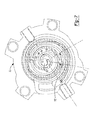
- FIG. 4 is an exploded view of the compression mechanism and capacity modulation system
- FIG. 5 is a cross-sectional view of a compression mechanism and capacity modulation system having an alternative lift ring and with the capacity modulation system in a full-capacity mode;
- FIG. 6 is a cross-sectional view of the compression mechanism and capacity modulation system of FIG. 5 in a reduced-capacity mode
- FIG. 7 is a cross-sectional view of a set of exemplary scroll members of the compressor.
- FIG. 8 is a cross-sectional view of another exemplary non-orbiting scroll member of the compressor.
- FIG. 9 is a cross-sectional view of yet another exemplary non-orbiting scroll member of the compressor.
- FIG. 10 is a partial cross-sectional view of another compressor having another capacity modulation system with a base ring installed correctly within the compressor according to the principles of the present disclosure
- FIG. 11 is a perspective view of the base ring of FIG. 10 ;
- FIG. 12 is a partial cross-sectional view of the compressor of FIG. 10 with the base ring installed incorrectly.
- Example embodiments are provided so that this disclosure will be thorough, and will fully convey the scope to those who are skilled in the art. Numerous specific details are set forth such as examples of specific components, devices, and methods, to provide a thorough understanding of embodiments of the present disclosure. It will be apparent to those skilled in the art that specific details need not be employed, that example embodiments may be embodied in many different forms and that neither should be construed to limit the scope of the disclosure. In some example embodiments, well-known processes, well-known device structures, and well-known technologies are not described in detail.
- first, second, third, etc. may be used herein to describe various elements, components, regions, layers and/or sections, these elements, components, regions, layers and/or sections should not be limited by these terms. These terms may be only used to distinguish one element, component, region, layer or section from another region, layer or section. Terms such as “first,” “second,” and other numerical terms when used herein do not imply a sequence or order unless clearly indicated by the context. Thus, a first element, component, region, layer or section discussed below could be termed a second element, component, region, layer or section without departing from the teachings of the example embodiments.
- Spatially relative terms such as “inner,” “outer,” “beneath,” “below,” “lower,” “above,” “upper,” and the like, may be used herein for ease of description to describe one element or feature's relationship to another element(s) or feature(s) as illustrated in the figures. Spatially relative terms may be intended to encompass different orientations of the device in use or operation in addition to the orientation depicted in the figures. For example, if the device in the figures is turned over, elements described as “below” or “beneath” other elements or features would then be oriented “above” the other elements or features. Thus, the example term “below” can encompass both an orientation of above and below. The device may be otherwise oriented (rotated 90 degrees or at other orientations) and the spatially relative descriptors used herein interpreted accordingly.
- a compressor 10 may include a hermetic shell assembly 12 , a bearing housing assembly 14 , a motor assembly 16 , a compression mechanism 18 , a seal assembly 20 , and a capacity modulation assembly 28 .
- the shell assembly 12 may house the bearing housing assembly 14 , the motor assembly 16 , the compression mechanism 18 , the seal assembly, and the capacity modulation assembly 28 .
- the shell assembly 12 may generally form a compressor housing and may include a cylindrical shell 29 , an end cap 32 at the upper end thereof, a transversely extending partition 34 , and a base 36 at a lower end thereof.
- the end cap 32 and partition 34 may generally define a discharge chamber 38 .
- the discharge chamber 38 may generally form a discharge muffler for compressor 10 . While the compressor 10 is illustrated as including the discharge chamber 38 , the present disclosure applies equally to direct discharge configurations.
- a discharge fitting may be attached to the shell assembly 12 at an opening in the end cap 32 .
- a suction gas inlet fitting may be attached to the shell assembly 12 at another opening.
- the partition 34 may include a discharge passage 44 therethrough providing communication between the compression mechanism 18 and the discharge chamber 38 .
- the bearing housing assembly 14 may be affixed to the shell 29 and may include a main bearing housing 46 and a bearing 48 disposed therein.
- the main bearing housing 46 may house the bearing 48 therein and may define an annular flat thrust bearing surface 54 on an axial end surface thereof.
- the motor assembly 16 may generally include a motor stator 58 , a rotor 60 , and a driveshaft 62 .
- the motor stator 58 may be press fit into the shell 29 .
- the driveshaft 62 may be rotatably driven by the rotor 60 and may be rotatably supported within the bearing 48 .
- the rotor 60 may be press fit on the driveshaft 62 .
- the driveshaft 62 may include an eccentric crankpin 64 .
- the compression mechanism 18 may generally include an orbiting scroll 68 and a non-orbiting scroll 70 .
- the orbiting scroll 68 may include an end plate 72 having a spiral wrap 74 on the upper surface thereof and an annular flat thrust surface 76 on the lower surface.
- the thrust surface 76 may interface with the annular flat thrust bearing surface 54 on the main bearing housing 46 .
- a cylindrical hub 78 may project downwardly from the thrust surface 76 and may have a drive bushing 80 rotatably disposed therein.
- the drive bushing 80 may include an inner bore in which the crank pin 64 is drivingly disposed.
- a flat surface of the crankpin 64 may drivingly engage a flat surface in a portion of the inner bore of the drive bushing 80 to provide a radially compliant driving arrangement.
- An Oldham coupling 82 may be engaged with the orbiting and non-orbiting scrolls 68 , 70 or the orbiting scroll 68 and the main bearing housing 46 to prevent relative rotation therebetween.
- the non-orbiting scroll 70 may include an end plate 84 defining a discharge passage 92 and having a spiral wrap 86 extending from a first side 87 thereof, and an annular hub 88 extending from a second side 89 thereof opposite the first side.
- the spiral wraps 74 , 86 may be meshingly engaged with one another defining pockets 94 , 96 , 98 , 100 , 102 , 104 ( FIG. 1 ). It is understood that the pockets 94 , 96 , 98 , 100 , 102 , 104 change throughout compressor operation.
- a first pocket may define a suction pocket in communication with a suction-pressure region 106 of the compressor 10 operating at a suction pressure (P s ) and a second pocket (pocket 104 in FIG. 1 ) may define a discharge pocket in communication with a discharge pressure region (e.g., discharge chamber 38 ) of the compressor 10 operating at a discharge pressure (P d ) via the discharge passage 92 .
- a discharge valve assembly 93 may be disposed within or adjacent the discharge passage 92 to allow fluid flow from the discharge pocket to the discharge chamber 38 and restrict or prevent fluid flow in the opposite direction.
- Pockets intermediate the first and second pockets may form intermediate compression pockets operating at intermediate pressures between the suction pressure (P s ) and the discharge pressure (P d ).
- the end plate 84 of the non-orbiting scroll 70 may additionally include a biasing passage 110 and one or more modulation ports 112 .
- the biasing passage 110 and modulation ports 112 may extend through the end plate 84 and may each be in fluid communication with intermediate compression pockets (e.g., pockets 96 , 98 , 100 , 102 ).
- the biasing passage 110 may be in fluid communication with one of the intermediate compression pockets operating at a higher pressure than ones of intermediate compression pockets in fluid communication with the modulation ports 112 .
- the biasing passage 110 may be disposed radially outward relative to the modulation ports 112 .
- the annular hub 88 may include first and second portions 116 , 118 forming a stepped region 120 therebetween.
- the first portion 116 may be located axially between the second portion 118 and the end plate 84 and may have an outer radial surface 122 having a greater diameter than a diameter of an outer radial surface 124 of the second portion 118 .
- the biasing passage 110 may extend through the annular hub 88 .
- the capacity modulation assembly 28 may include a modulation valve ring 126 , a modulation lift ring 128 , and a modulation control valve assembly 132 ( FIGS. 2 and 3 ).
- the modulation valve ring 126 may include an inner radial surface 134 , an outer radial surface 136 , an upper rim 137 , and a lower axial end surface 138 defining an annular recess 140 , and first and second passages 144 , 146 .
- the inner radial surface 134 may include first and second portions 148 , 150 .
- An axially upwardly facing surface 152 (i.e., a surface facing an axial direction parallel to a rotational axis of the driveshaft 62 ) may be disposed between the first and second portions 148 , 150 .
- the first portion 148 may have diameter that is less than a diameter of the second portion 150 .
- the modulation valve ring 126 may be received on the hub 88 such that the first portion 116 of the hub 88 is sealingly engaged (via seal 154 ) with the first portion 148 of the inner radial surface 134 of the modulation valve ring 126 .
- the modulation lift ring 128 may be located within annular recess 140 and may include an annular seal body 158 and a base ring 160 .
- the modulation valve ring 126 and the modulation lift ring 128 may cooperate to define a modulation control chamber 174 disposed within the recess 140 .
- the first passage 144 may be in fluid communication with modulation control chamber 174 .
- the base ring 160 may support the seal body 158 and may include a series of bosses or protrusions 177 contacting the end plate 84 and defining radial flow passages 178 between the end plate 84 and the base ring 160 .
- the base ring 160 can be formed from a metallic material, such as cast iron, for example.
- the seal body 158 may be a single, unitary body formed from a polymeric material, such as Teflon®, for example.
- the seal body 158 may include a generally U-shaped cross section having a base portion 162 , an inner lip 163 and an outer lip 164 .
- the lips 163 , 164 may be integrally formed with the base portion 162 .
- the base portion 162 may be a generally flat, annular member that extends radially (i.e., in a direction perpendicular to the rotational axis of the driveshaft 62 ).
- the inner lip 163 may extend from a radially inner edge of the base portion 162
- the outer lip 164 may extend from a radially outer edge of the base portion 162 .
- the inner lip 163 may extend from the base portion 162 axially upward (i.e., toward the seal assembly 20 ) and radially inward (i.e., toward the hub 88 ).
- the outer lip 164 may extend from the base portion 162 axially upward (i.e., toward the seal assembly 20 ) and radially outward (i.e., away from the hub 88 ).
- the lips 163 , 164 may be sealingly engaged with respective sidewalls 166 , 168 of the annular recess 140 .
- Fluid pressure within the modulation control chamber 174 may force the lips 163 , 164 into sealing contact with the sidewalls 166 , 168 and keep the seal body 158 stationary while the modulation valve ring 126 moves between the positions shown in FIGS. 2 and 3 .
- the above configuration of the modulation lift ring 128 reduces the number of components of the capacity modulation assembly 28 , simplifies assembly and installation of the capacity modulation assembly 28 , and reduces material swelling that can occur in O-ring seals when refrigerant and/or oil are introduced into the compressor 10 .
- the modulation lift ring 128 described above also improves robustness and reliability of the capacity modulation assembly 28 .
- the amount that the lips 163 , 164 extend upward (in an axial direction) into the recess 140 allow for sealing contact with the sidewalls 166 , 168 relatively far up into the recess 140 , which allows for a greater amount of axial travel of the modulation valve ring 126 relative to the modulation lift ring 128 .
- the lift ring 228 may be a single unitary body formed from a polymeric material. Bosses or protrusions 227 (like protrusions 177 ) can be integrally formed on the end plate 84 and can provide radial flow passages 178 ( FIG. 6 ) between the end plate 84 and the lift ring 228 . In other words, the base ring 160 can be integrally formed with the end plate 84 .
- a plurality of apertures can be cross-drilled in a single raised ring integrally formed on the end plate 84 to form the radial flow passages 178 .
- the base ring 160 and seal body 158 described above can be integrally formed as a single, unitary polymeric body having the U-shaped cross section and a plurality of protrusions contacting the end plate 84 and defining radial flow passages 178 ( FIG. 3 ) between the end plate 84 and the lift ring 228 .
- fasteners can fixedly attach the lift ring 128 , 228 to the end plate 84 and/or base ring 160 .
- a separate ring-shaped plate or a plurality of washers can be placed on the base portion 162 of the U-shaped seal body 158 and fasteners can extend through the ring-shaped plate (or washers), through the seal body 158 and into the base ring 160 or end plate 84 to sandwich the seal body 158 between the ring-shaped plate (or washers) and the base ring 160 or end plate 84 .
- the modulation valve ring 126 may be used in combination with a lift ring having a different configuration than the lift ring 128 described above.
- the modulation valve ring 126 can be used in combination with a lift ring including an annular body with O-ring seals and integrally formed bosses extending from the annular body (e.g., like the lift ring disclosed in Assignee's commonly owned U.S. Pat. No. 8,585,382, the disclosure of which is incorporated by reference).
- the lift ring 128 could be used in combination with a valve ring having a different configuration that the valve ring 126 described above.
- the seal assembly 20 may form a floating seal assembly and may be sealingly engaged with the non-orbiting scroll 70 and the modulation valve ring 126 to define an axial biasing chamber 180 that communicates with the biasing passage 110 . More specifically, the seal assembly 20 may be sealingly engaged with the outer radial surface 124 of the annular hub 88 and the second portion 150 of the modulation valve ring 126 .
- the axial biasing chamber 180 may be defined axially between a lower axial end surface 182 of the seal assembly 20 and the axially upwardly facing surface 152 of the modulation valve ring 126 and the stepped region 120 of the annular hub 88 .
- the second passage 146 may be in fluid communication with the axial biasing chamber 180 .
- the modulation control valve assembly 132 may include a solenoid-operated valve and may be in fluid communication with the suction-pressure region 106 and the first and second passages 144 , 146 in the modulation valve ring 126 . During operation of the compressor 10 , the modulation control valve assembly 132 may be operated in first and second modes. FIGS. 2 and 3 schematically illustrate operation of the modulation control valve assembly 132 . In the first mode, shown in FIG. 2 , the modulation control valve assembly 132 may provide fluid communication between the modulation control chamber 174 and the suction-pressure region 106 via the first passage 144 , thereby lowering the fluid pressure within the modulation control chamber 174 to suction pressure.
- the relatively higher fluid pressure within the axial biasing chamber 180 will force the modulation valve ring 126 axially downward into contact with the end plate 84 such that the lower axial end surface 138 of the modulation valve ring 126 closes the modulation ports 112 , as shown in FIG. 2 .
- the modulation control valve assembly 132 may provide fluid communication between the modulation control chamber 174 and the axial biasing chamber 180 via the second passage 146 , thereby raising the fluid pressure within the modulation control chamber 174 to the same or similar intermediate pressure as the axial biasing chamber 180 and the intermediate pocket in communication with the axial biasing chamber 180 via the biasing passage 110 .
- the fluid pressure within the modulation control chamber 174 will force the modulation valve ring 126 axially upward relative to the end plate 84 such that the lower axial end surface 138 of the modulation valve ring 126 is spaced apart from the end plate 84 to open the modulation ports 112 , as shown in FIG. 3 .
- the intermediate-pressure fluid within the modulation control chamber 174 will force the modulation valve ring 126 upward such that the axially upwardly facing surface 152 of the modulation valve ring 126 will contact the lower axial end surface 182 of the seal assembly 20 and urge the seal assembly 20 axially upward against the partition 34 .
- the ability of the axially upwardly facing surface 152 of the modulation valve ring 126 to contact the seal assembly 20 and force the seal assembly 20 upward increases the total axial upward force that is exerted on the seal assembly 20 . That is, the configuration described above adds surface area against which intermediate-pressure fluid can push the seal assembly 20 axially upward. More specifically, the surface areas against which the intermediate-pressure fluid can push the seal assembly 20 include lower axial end surface 182 of the seal assembly 20 and the portion of axially downwardly facing surface 190 of the recess 140 that is disposed radially outward relative to the outer periphery of the axial biasing chamber 180 . The intermediate-pressure fluid also biases the non-orbiting scroll 70 axially toward the orbiting scroll 68 .
- the increase in surface area against which the intermediate-pressure fluid can push the seal assembly 20 upward allows the biasing passage 110 to be positioned such that the fluid pocket with which it communicates can be at a lower pressure (i.e., the biasing passage 110 can be located at a position that is further radially outward). Even with the lower intermediate pressure in the axial biasing chamber 180 and in the modulation control chamber 174 , the increased surface area over which the lower intermediate pressure fluid can push allows for adequate total upward force against the seal assembly 20 .
- the modulation ports 112 can be positioned at higher pressure locations (i.e., the modulation ports 112 can be positioned closer to the discharge passage 92 ). This allows for improved load matching and system efficiency (i.e., a larger capacity step between part-load capacity and full-load capacity).
- the reduced pressure in the axial biasing chamber 180 reduces the friction load between the scrolls 68 , 70 (i.e., due to downward force biasing the non-orbiting scroll 70 axially against the orbiting scroll 68 ), thereby reducing wear on the scrolls 68 , 70 , while still providing sufficient sealing between the scrolls 68 , 70 and between the seal assembly 20 and the partition 34 . This leads to less power consumption and improved efficiency.
- the configuration of the capacity modulation assembly 28 of the present disclosure may increase the capacity step between full and reduced capacities, and may improve stability in balanced-pressure and defrost conditions during partial-load operation.
- FIGS. 7-9 depict exemplary configurations in which the position of the biasing passage 110 has been moved to lower pressure locations and/or the modulation ports 112 have been moved to higher pressure locations relative to other compressors (i.e., compressors having capacity modulation assemblies that differ from the capacity modulation assembly 28 described above).
- a ratio of angle A 1 to angle A 2 may be between about 0.65 and 0.75.
- Angle A 1 may be a wrap angle between a suction seal-off location 192 (i.e., the radially outermost location at which the wrap 86 of the non-orbiting scroll 70 and the wrap 74 of the orbiting scroll 68 contact each other to initially seal off a pocket between the wraps 74 , 86 ) and a selected one of the modulation ports 112 .
- Angle A 2 may be a wrap angle between the suction seal-off location 192 and the biasing passage 110 .
- the ratio of angle A 1 to angle A 2 may be between 0.66 and 0.73. In some configurations, the ratio of angle A 1 to angle A 2 may be between 0.71 and 0.73. In some configurations, the ratio of angle A 1 to angle A 2 may be between 0.66 and 0.69.
- FIGS. 10-12 another compressor 300 (partially shown in FIGS. 10 and 12 ) is provided that may include a shell assembly 312 , a bearing housing assembly (not shown), a motor assembly (not shown), a compression mechanism 318 , a seal assembly 320 , and a capacity modulation assembly 328 .
- the structure and function of the shell assembly 312 , bearing housing assembly, motor assembly and seal assembly 320 may be similar or identical to that of the shell assembly 12 , bearing housing assembly 14 , motor assembly 16 and seal assembly 20 described above, and therefore, will not be described again in detail.
- the compression mechanism 318 includes an orbiting scroll 368 and a non-orbiting scroll 370 .
- the structure and function of the orbiting scroll 368 may be similar or identical to that of the orbiting scroll 68 described above, and therefore, will not be described again in detail.
- the structure and function of the non-orbiting scroll 370 may be similar or identical to that of the non-orbiting scroll 70 described above, apart from any exceptions described below. Therefore, similar features will not be described again in detail.
- a second side 389 of an end plate 384 of the non-orbiting scroll 370 may include a first annular surface 390 and a second annular surface 391 surrounding the first annular surface 390 .
- the end plate 384 may include an annular step 392 disposed radially between and directly adjacent the first and second annular surfaces 390 , 391 .
- the first and second annular surfaces 390 , 391 define first and second planes that are parallel and axially offset from each other (i.e., offset in a direction parallel to a rotational axis of a driveshaft of the compressor 300 ).
- the second annular surface 391 may be disposed axially between the first annular surface 390 and the orbiting scroll 368 .
- One or more modulation ports 412 (similar or identical to modulation port(s) 112 ) may extend through the first annular surface 390 .
- the capacity modulation assembly 328 may include a modulation valve ring 426 (similar or identical to the modulation valve ring 126 ), a modulation lift ring 428 , and a modulation control valve assembly 432 (similar or identical to the modulation control valve assembly 132 ).
- the modulation valve ring 426 may be spaced apart from the first annular surface 390 of the non-orbiting scroll 370 in one position (shown in FIG. 10 ) to allow fluid flow through the modulation port 412 .
- the modulation valve ring 426 may contact the first annular surface 390 in another position (not shown; like the position shown in FIG. 2 ) to restrict or prevent fluid flow through the modulation port 412 .
- the modulation lift ring 428 may include an annular seal body 458 (similar or identical to the annular seal body 158 ) and a base ring 460 .
- the modulation lift ring 428 provides at least the same benefits and advantages as the lift ring 128 described above.
- the base ring 460 may include a main body 461 , a plurality of first protrusions or bosses 477 , and a plurality of second protrusions or bosses 478 .
- the main body 461 may be an annular disk having inner and outer diametrical surfaces 463 , 465 that are sized so that the main body 461 can fit within an annular recess 440 in the modulation valve ring 426 .
- the inner diametrical surface 463 defines an inner diameter of the main body 461 that is smaller than a diameter defined by the annular step 392 of the non-orbiting scroll 370 .
- first and second bosses 477 , 478 may contact the second annular surface 391 of the non-orbiting scroll 370 .
- the first bosses 477 may be radially disposed entirely between the inner and outer diametrical surfaces 463 , 465 of the main body 461 .
- Each of the second bosses 478 includes a flange portion 479 that extends radially outward beyond the outer diametrical surface 465 of the main body 461 .
- the first bosses 477 could have the same size and shape as the second bosses 478 .
- the two second bosses 478 are disposed 180 degrees apart from each other.
- a distance between radially outer edges 480 of the two second bosses 478 i.e., a distance along a line L that intersects and is perpendicular to an axis A of angular of rotational symmetry of the main body 461 ) is greater than an outer diameter of the annular recess 440 of the modulation valve ring 426 .
- an axial thickness T 1 of the flange portion 479 i.e., a thickness in a direction parallel to the axis A and the rotational axis of the driveshaft
- T 2 of the annular step 392 is less than an axial thickness T 2 of the annular step 392 .
- the axial distance between the first annular surface 390 of the non-orbiting scroll 370 and a lower axial end surface 438 of the modulation valve ring 426 is less than the axial distance between the flange portion 479 and the lower axial end surface 438 .
- the axial thickness T 1 of the flange portion 479 is sized so that, as long as the base ring 460 is installed correctly (as shown in FIG. 10 ), the flange portions 479 will not prevent the modulation valve ring 426 from moving along its entire range of motion.
- the flange portions 479 of the second bosses 478 will contact the lower axial end surface 438 of the modulation valve ring 426 , and the main body 461 will contact the first annular surface 390 of the non-orbiting scroll 370 .
- Such contact between the flange portions 479 and the modulation valve ring 426 will prevent the modulation valve ring 426 from being positioned close enough to the first annular surface 390 to allow clearance for a mounting tab or rib 333 of a partition 334 of the shell assembly 312 from seating on an axial end 330 of a cylindrical shell 329 of the shell assembly 312 .
- the structure of the base ring 460 is a poka-yoke structure that prevents the shell assembly 312 from being welded shut while the base ring 460 is installed incorrectly. Therefore, if the base ring 460 is inadvertently installed upside down, the manufacturer will realize that there has been an assembly error before the shell assembly 312 can be sealed shut. In other capacity modulation assemblies, the shell assembly is capable of being fully assembled and welded shut without the manufacturer realizing that the base ring is installed upside down.
- Such upside down installation of the base ring can prevent the capacity modulation assembly from functioning properly (e.g., the modulation valve ring is prevented from moving into a full-capacity position in which the modulation valve ring closes off the modulation port in the non-orbiting scroll).
Landscapes
- Engineering & Computer Science (AREA)
- Mechanical Engineering (AREA)
- General Engineering & Computer Science (AREA)
- Physics & Mathematics (AREA)
- Fluid Mechanics (AREA)
- Rotary Pumps (AREA)
Abstract
Description
Claims (23)
Priority Applications (1)
| Application Number | Priority Date | Filing Date | Title |
|---|---|---|---|
| US15/651,471 US10066622B2 (en) | 2015-10-29 | 2017-07-17 | Compressor having capacity modulation system |
Applications Claiming Priority (10)
| Application Number | Priority Date | Filing Date | Title |
|---|---|---|---|
| US201562247957P | 2015-10-29 | 2015-10-29 | |
| US201562247967P | 2015-10-29 | 2015-10-29 | |
| PCT/CN2016/103763 WO2017071641A1 (en) | 2015-10-29 | 2016-10-28 | Compressor having capacity modulation system |
| CN201621155252.2 | 2016-10-31 | ||
| CN201610930347 | 2016-10-31 | ||
| CN201610930347.5 | 2016-10-31 | ||
| CN201621155252U | 2016-10-31 | ||
| CN201621155252.2 | 2016-10-31 | ||
| CN201610930347.5A CN106979153B (en) | 2015-10-29 | 2016-10-31 | Compressor with capacity modulation |
| US15/651,471 US10066622B2 (en) | 2015-10-29 | 2017-07-17 | Compressor having capacity modulation system |
Related Parent Applications (1)
| Application Number | Title | Priority Date | Filing Date |
|---|---|---|---|
| PCT/CN2016/103763 Continuation WO2017071641A1 (en) | 2015-10-29 | 2016-10-28 | Compressor having capacity modulation system |
Publications (2)
| Publication Number | Publication Date |
|---|---|
| US20170314558A1 US20170314558A1 (en) | 2017-11-02 |
| US10066622B2 true US10066622B2 (en) | 2018-09-04 |
Family
ID=60090078
Family Applications (2)
| Application Number | Title | Priority Date | Filing Date |
|---|---|---|---|
| US15/646,654 Active US10087936B2 (en) | 2015-10-29 | 2017-07-11 | Compressor having capacity modulation system |
| US15/651,471 Active US10066622B2 (en) | 2015-10-29 | 2017-07-17 | Compressor having capacity modulation system |
Family Applications Before (1)
| Application Number | Title | Priority Date | Filing Date |
|---|---|---|---|
| US15/646,654 Active US10087936B2 (en) | 2015-10-29 | 2017-07-11 | Compressor having capacity modulation system |
Country Status (2)
| Country | Link |
|---|---|
| US (2) | US10087936B2 (en) |
| CN (1) | CN207377799U (en) |
Cited By (15)
| Publication number | Priority date | Publication date | Assignee | Title |
|---|---|---|---|---|
| US10323638B2 (en) | 2015-03-19 | 2019-06-18 | Emerson Climate Technologies, Inc. | Variable volume ratio compressor |
| US10495086B2 (en) | 2012-11-15 | 2019-12-03 | Emerson Climate Technologies, Inc. | Compressor valve system and assembly |
| US10598180B2 (en) | 2015-07-01 | 2020-03-24 | Emerson Climate Technologies, Inc. | Compressor with thermally-responsive injector |
| US10753352B2 (en) | 2017-02-07 | 2020-08-25 | Emerson Climate Technologies, Inc. | Compressor discharge valve assembly |
| US10801495B2 (en) | 2016-09-08 | 2020-10-13 | Emerson Climate Technologies, Inc. | Oil flow through the bearings of a scroll compressor |
| US10890186B2 (en) | 2016-09-08 | 2021-01-12 | Emerson Climate Technologies, Inc. | Compressor |
| US10907633B2 (en) | 2012-11-15 | 2021-02-02 | Emerson Climate Technologies, Inc. | Scroll compressor having hub plate |
| US10954940B2 (en) | 2009-04-07 | 2021-03-23 | Emerson Climate Technologies, Inc. | Compressor having capacity modulation assembly |
| US10962008B2 (en) | 2017-12-15 | 2021-03-30 | Emerson Climate Technologies, Inc. | Variable volume ratio compressor |
| US10995753B2 (en) | 2018-05-17 | 2021-05-04 | Emerson Climate Technologies, Inc. | Compressor having capacity modulation assembly |
| US11022119B2 (en) | 2017-10-03 | 2021-06-01 | Emerson Climate Technologies, Inc. | Variable volume ratio compressor |
| US11655813B2 (en) | 2021-07-29 | 2023-05-23 | Emerson Climate Technologies, Inc. | Compressor modulation system with multi-way valve |
| US11656003B2 (en) | 2019-03-11 | 2023-05-23 | Emerson Climate Technologies, Inc. | Climate-control system having valve assembly |
| US11846287B1 (en) | 2022-08-11 | 2023-12-19 | Copeland Lp | Scroll compressor with center hub |
| US11965507B1 (en) | 2022-12-15 | 2024-04-23 | Copeland Lp | Compressor and valve assembly |
Families Citing this family (7)
| Publication number | Priority date | Publication date | Assignee | Title |
|---|---|---|---|---|
| US9989057B2 (en) | 2014-06-03 | 2018-06-05 | Emerson Climate Technologies, Inc. | Variable volume ratio scroll compressor |
| US10378540B2 (en) | 2015-07-01 | 2019-08-13 | Emerson Climate Technologies, Inc. | Compressor with thermally-responsive modulation system |
| US10378542B2 (en) | 2015-07-01 | 2019-08-13 | Emerson Climate Technologies, Inc. | Compressor with thermal protection system |
| CN207377799U (en) | 2015-10-29 | 2018-05-18 | 艾默生环境优化技术有限公司 | Compressor |
| US10774833B2 (en) * | 2017-01-11 | 2020-09-15 | James William Bush | Scroll-type machine |
| WO2023177410A1 (en) * | 2022-03-16 | 2023-09-21 | Emerson Climate Technologies, Inc. | Modulated compressor and valve assembly |
| WO2024002338A1 (en) * | 2022-06-30 | 2024-01-04 | 谷轮环境科技(苏州)有限公司 | Fixed scroll assembly, scroll compressor, and method for machining fixed scroll assembly |
Citations (224)
| Publication number | Priority date | Publication date | Assignee | Title |
|---|---|---|---|---|
| US4058988A (en) | 1976-01-29 | 1977-11-22 | Dunham-Bush, Inc. | Heat pump system with high efficiency reversible helical screw rotary compressor |
| US4216661A (en) | 1977-12-09 | 1980-08-12 | Hitachi, Ltd. | Scroll compressor with means for end plate bias and cooled gas return to sealed compressor spaces |
| GB2107829A (en) | 1981-06-09 | 1983-05-05 | Dudley Vernon Steynor | Thermostatic valves, and solar water heating systems incorporating the same |
| US4382370A (en) | 1980-10-31 | 1983-05-10 | Hitachi, Ltd. | Refrigerating system using scroll type compressor |
| US4383805A (en) | 1980-11-03 | 1983-05-17 | The Trane Company | Gas compressor of the scroll type having delayed suction closing capacity modulation |
| US4389171A (en) | 1981-01-15 | 1983-06-21 | The Trane Company | Gas compressor of the scroll type having reduced starting torque |
| US4475360A (en) | 1982-02-26 | 1984-10-09 | Hitachi, Ltd. | Refrigeration system incorporating scroll type compressor |
| US4497615A (en) | 1983-07-25 | 1985-02-05 | Copeland Corporation | Scroll-type machine |
| US4545742A (en) | 1982-09-30 | 1985-10-08 | Dunham-Bush, Inc. | Vertical axis hermetic helical screw rotary compressor with discharge gas oil mist eliminator and dual transfer tube manifold for supplying liquid refrigerant and refrigerant vapor to the compression area |
| JPS60259794A (en) | 1984-06-04 | 1985-12-21 | Hitachi Ltd | Heat pump type air conditioner |
| US4580949A (en) | 1984-03-21 | 1986-04-08 | Matsushita Electric Industrial Co., Ltd. | Sliding vane type rotary compressor |
| US4609329A (en) | 1985-04-05 | 1986-09-02 | Frick Company | Micro-processor control of a movable slide stop and a movable slide valve in a helical screw rotary compressor with an enconomizer inlet port |
| KR870000015B1 (en) | 1983-09-30 | 1987-01-28 | 가부시기 가이샤 도시바 | Scroll type compressor |
| US4727725A (en) | 1985-05-20 | 1988-03-01 | Hitachi, Ltd. | Gas injection system for screw compressor |
| JPS6385277A (en) | 1986-09-29 | 1988-04-15 | Toshiba Corp | Scroll capacity type machinery |
| JPS63205482A (en) | 1987-02-23 | 1988-08-24 | Hitachi Ltd | Discharge bypass valve for scroll compressor |
| US4774816A (en) | 1986-12-04 | 1988-10-04 | Hitachi, Ltd. | Air conditioner or refrigerating plant incorporating scroll compressor |
| US4818195A (en) | 1986-02-26 | 1989-04-04 | Hitachi, Ltd. | Scroll compressor with valved port for each compression chamber |
| US4846633A (en) | 1986-11-27 | 1989-07-11 | Mitsubishi Denki Kabushiki Kaisha | Variable-capacity scroll-type compressor |
| US4877382A (en) | 1986-08-22 | 1989-10-31 | Copeland Corporation | Scroll-type machine with axially compliant mounting |
| US4886425A (en) | 1987-03-26 | 1989-12-12 | Mitsubishi Jukogyo Kabushiki Kaisha | Capacity control device of scroll-type fluid compressor |
| JPH0281982A (en) | 1988-09-20 | 1990-03-22 | Matsushita Refrig Co Ltd | Scroll compressor |
| US4940395A (en) | 1987-12-08 | 1990-07-10 | Sanden Corporation | Scroll type compressor with variable displacement mechanism |
| JPH0381588A (en) | 1989-08-23 | 1991-04-05 | Hitachi Ltd | Capacity control device for scroll type compressor |
| US5040952A (en) | 1989-02-28 | 1991-08-20 | Kabushiki Kaisha Toshiba | Scroll-type compressor |
| US5055010A (en) | 1990-10-01 | 1991-10-08 | Copeland Corporation | Suction baffle for refrigeration compressor |
| US5059098A (en) | 1989-02-02 | 1991-10-22 | Kabushiki Kaisha Toyoda Jidoshokki Seisakusho | Apparatus for varying capacity of scroll type compressor |
| US5071323A (en) | 1988-08-31 | 1991-12-10 | Kabushiki Kaisha Toshiba | Scroll compressor with bypass release passage in stationary scroll member |
| US5074760A (en) | 1988-08-12 | 1991-12-24 | Mitsubishi Jukogyo Kabushiki Kaisha | Scroll type compressor |
| US5080056A (en) | 1991-05-17 | 1992-01-14 | General Motors Corporation | Thermally sprayed aluminum-bronze coatings on aluminum engine bores |
| US5085565A (en) | 1990-09-24 | 1992-02-04 | Carrier Corporation | Axially compliant scroll with rotating pressure chambers |
| JPH04272490A (en) | 1990-10-01 | 1992-09-29 | Copeland Corp | Scroll type compressor |
| US5169294A (en) | 1991-12-06 | 1992-12-08 | Carrier Corporation | Pressure ratio responsive unloader |
| USRE34148E (en) | 1985-06-18 | 1992-12-22 | Sanden Corporation | Scroll type compressor with variable displacement mechanism |
| US5192195A (en) | 1990-11-14 | 1993-03-09 | Mitsubishi Jukogyo Kabushiki Kaisha | Scroll type compressor with separate control block |
| US5193987A (en) | 1990-11-14 | 1993-03-16 | Mitsubishi Jukogyo Kabushiki Kaisha | Scroll type compressor |
| US5240389A (en) | 1991-07-26 | 1993-08-31 | Kabushiki Kaisha Toshiba | Scroll type compressor |
| US5253489A (en) | 1991-04-02 | 1993-10-19 | Sanden Corporation | Scroll type compressor with injection mechanism |
| US5356271A (en) | 1992-02-06 | 1994-10-18 | Mitsubishi Jukogyo Kabushiki Kaisha | Capacity control mechanism for scroll-type compressor |
| US5451146A (en) | 1992-04-01 | 1995-09-19 | Nippondenso Co., Ltd. | Scroll-type variable-capacity compressor with bypass valve |
| JPH07293456A (en) | 1994-04-28 | 1995-11-07 | Sanyo Electric Co Ltd | Scroll compressor |
| US5482637A (en) | 1993-07-06 | 1996-01-09 | Ford Motor Company | Anti-friction coating composition containing solid lubricants |
| US5551846A (en) | 1995-12-01 | 1996-09-03 | Ford Motor Company | Scroll compressor capacity control valve |
| US5557897A (en) | 1992-02-20 | 1996-09-24 | Braas Gmbh | Fastening device for a roof sealing strip or the like |
| JPH08247053A (en) | 1995-03-15 | 1996-09-24 | Mitsubishi Electric Corp | Scroll compressor |
| US5562426A (en) | 1994-06-03 | 1996-10-08 | Kabushiki Kaisha Toyoda Jidoshokki Seisakusho | Scroll type refrigerant compressor |
| JPH08320079A (en) | 1995-05-24 | 1996-12-03 | Piolax Inc | Flow control valve |
| CN1137614A (en) | 1995-06-07 | 1996-12-11 | 科普兰公司 | Capacity modulated scroll machine |
| US5607288A (en) | 1993-11-29 | 1997-03-04 | Copeland Corporation | Scroll machine with reverse rotation protection |
| US5611674A (en) | 1995-06-07 | 1997-03-18 | Copeland Corporation | Capacity modulated scroll machine |
| US5613841A (en) | 1995-06-07 | 1997-03-25 | Copeland Corporation | Capacity modulated scroll machine |
| US5639225A (en) | 1994-05-30 | 1997-06-17 | Nippondenso Co., Ltd. | Scroll type compressor |
| US5640854A (en) | 1995-06-07 | 1997-06-24 | Copeland Corporation | Scroll machine having liquid injection controlled by internal valve |
| JPH09177689A (en) | 1995-12-27 | 1997-07-11 | Daikin Ind Ltd | Hermetic compressor |
| CN1158945A (en) | 1995-12-19 | 1997-09-10 | 科普兰公司 | Scroll machine with capacity modulation |
| CN1158944A (en) | 1995-12-05 | 1997-09-10 | 松下电器产业株式会社 | Eddy gas compressor with by-pass valve |
| US5674058A (en) | 1994-06-08 | 1997-10-07 | Nippondenso Co., Ltd. | Scroll-type refrigerant compressor |
| US5707210A (en) | 1995-10-13 | 1998-01-13 | Copeland Corporation | Scroll machine with overheating protection |
| EP0822335A2 (en) | 1996-08-02 | 1998-02-04 | Copeland Corporation | Scroll compressor |
| US5722257A (en) | 1995-10-11 | 1998-03-03 | Denso Corporation | Compressor having refrigerant injection ports |
| US5885063A (en) | 1996-05-07 | 1999-03-23 | Matshushita Electric Industrial Co., Ltd. | Variable capacity scroll compressor |
| JPH11107950A (en) | 1997-10-06 | 1999-04-20 | Matsushita Electric Ind Co Ltd | Injection device of compressor |
| JPH11324950A (en) | 1998-05-19 | 1999-11-26 | Mitsubishi Electric Corp | Scroll compressor |
| US5993171A (en) | 1996-06-25 | 1999-11-30 | Sanden Corporation | Scroll-type compressor with variable displacement mechanism |
| US5993177A (en) | 1996-05-21 | 1999-11-30 | Sanden Corporation | Scroll type compressor with improved variable displacement mechanism |
| JP2000104684A (en) | 1998-09-29 | 2000-04-11 | Nippon Soken Inc | Variable displacement compressor |
| US6047557A (en) | 1995-06-07 | 2000-04-11 | Copeland Corporation | Adaptive control for a refrigeration system using pulse width modulated duty cycle scroll compressor |
| JP2000161263A (en) | 1998-11-27 | 2000-06-13 | Mitsubishi Electric Corp | Capacity control scroll compressor |
| US6095765A (en) | 1998-03-05 | 2000-08-01 | Carrier Corporation | Combined pressure ratio and pressure differential relief valve |
| US6102671A (en) | 1997-09-04 | 2000-08-15 | Matsushita Electric Industrial Co., Ltd. | Scroll compressor |
| US6123517A (en) | 1997-11-24 | 2000-09-26 | Copeland Corporation | Scroll machine with capacity modulation |
| US6123528A (en) | 1998-04-06 | 2000-09-26 | Scroll Technologies | Reed discharge valve for scroll compressors |
| US6132179A (en) | 1997-09-09 | 2000-10-17 | Sanden Corporation | Scroll type compressor enabling a soft start with a simple structure |
| US6139291A (en) | 1999-03-23 | 2000-10-31 | Copeland Corporation | Scroll machine with discharge valve |
| US6139287A (en) | 1995-12-19 | 2000-10-31 | Daikin Industries, Ltd. | Scroll type fluid machine |
| US6149401A (en) | 1997-10-27 | 2000-11-21 | Denso Corporation | Variable discharge-amount compressor for refrigerant cycle |
| JP2000329078A (en) | 1999-05-20 | 2000-11-28 | Fujitsu General Ltd | Scroll compressor |
| WO2000073659A1 (en) | 1999-06-01 | 2000-12-07 | Lg Electronics Inc. | Apparatus for preventing vacuum compression of scroll compressor |
| US6164940A (en) | 1998-09-11 | 2000-12-26 | Sanden Corporation | Scroll type compressor in which a soft starting mechanism is improved with a simple structure |
| EP1067289A2 (en) | 1999-07-07 | 2001-01-10 | Copeland Corporation | Scroll compressor discharge muffler |
| US6176686B1 (en) | 1999-02-19 | 2001-01-23 | Copeland Corporation | Scroll machine with capacity modulation |
| US6179589B1 (en) | 1999-01-04 | 2001-01-30 | Copeland Corporation | Scroll machine with discus discharge valve |
| US6202438B1 (en) | 1999-11-23 | 2001-03-20 | Scroll Technologies | Compressor economizer circuit with check valve |
| EP1087142A2 (en) | 1999-09-21 | 2001-03-28 | Copeland Corporation | Scroll compressor capacity control |
| US6210120B1 (en) | 1999-03-19 | 2001-04-03 | Scroll Technologies | Low charge protection vent |
| US6231316B1 (en) | 1998-07-01 | 2001-05-15 | Denso Corporation | Scroll-type variable-capacity compressor |
| US20010010800A1 (en) | 1998-03-19 | 2001-08-02 | Hirokatsu Kohsokabe | Displacement type fluid machine |
| US6273691B1 (en) | 1996-07-22 | 2001-08-14 | Matsushita Electric Industrial Co., Ltd. | Scroll gas compressor having asymmetric bypass holes |
| US6293767B1 (en) | 2000-02-28 | 2001-09-25 | Copeland Corporation | Scroll machine with asymmetrical bleed hole |
| US6293776B1 (en) | 2000-07-12 | 2001-09-25 | Scroll Technologies | Method of connecting an economizer tube |
| US6322340B1 (en) | 1999-06-08 | 2001-11-27 | Mitsubishi Heavy Industries, Ltd. | Scroll compressor having a divided orbiting scroll end plate |
| US6350111B1 (en) | 2000-08-15 | 2002-02-26 | Copeland Corporation | Scroll machine with ported orbiting scroll member |
| US20020039540A1 (en) | 2000-09-29 | 2002-04-04 | Kazuhiro Kuroki | Scroll type compressor and method for compressing gas |
| US6379123B1 (en) | 1997-05-12 | 2002-04-30 | Matsushita Electric Industrial Co., Ltd. | Capacity control scroll compressor |
| CN1349053A (en) | 2000-10-16 | 2002-05-15 | 科普兰公司 | Double volume ratio whiral machinery |
| US6412293B1 (en) | 2000-10-11 | 2002-07-02 | Copeland Corporation | Scroll machine with continuous capacity modulation |
| US6413058B1 (en) | 2000-11-21 | 2002-07-02 | Scroll Technologies | Variable capacity modulation for scroll compressor |
| US6428286B1 (en) | 1997-05-12 | 2002-08-06 | Matsushita Electric Industrial Co., Ltd. | Capacity control scroll compressor |
| EP1241417A1 (en) | 2001-03-16 | 2002-09-18 | Copeland Corporation | Digital controller for scroll compressor condensing unit |
| US6454551B2 (en) | 2000-05-24 | 2002-09-24 | Kabushiki Kaisha Toyoda Jidoshokki Seisakusho | Seal structure in a scroll type compressor |
| US6457948B1 (en) | 2001-04-25 | 2002-10-01 | Copeland Corporation | Diagnostic system for a compressor |
| US6464481B2 (en) | 2000-09-29 | 2002-10-15 | Kabushiki Kaisha Toyota Jidoshokki | Scroll compressors |
| US6478550B2 (en) | 1998-06-12 | 2002-11-12 | Daikin Industries, Ltd. | Multi-stage capacity-controlled scroll compressor |
| US6506036B2 (en) | 2000-09-13 | 2003-01-14 | Kabushiki Kaisha Toyota Jidoshokki | Scroll compressors |
| US20030044296A1 (en) | 2001-09-05 | 2003-03-06 | Jianxiong Chen | Compressor discharge valve |
| JP2003074481A (en) | 2001-08-31 | 2003-03-12 | Sanyo Electric Co Ltd | Scroll compressor |
| JP2003074482A (en) | 2001-08-31 | 2003-03-12 | Sanyo Electric Co Ltd | Scroll compressor |
| US6544016B2 (en) | 2000-09-14 | 2003-04-08 | Kabushiki Kaisha Toyota Jidoshokki | Scroll compressors |
| US6558143B2 (en) | 2000-09-18 | 2003-05-06 | Kabushiki Kaisha Toyota Jidoshokki | Scroll compressors |
| US6589035B1 (en) | 1996-10-04 | 2003-07-08 | Hitachi, Ltd. | Scroll compressor having a valved back-pressure chamber and a bypass for over-compression |
| JP2003227479A (en) | 2002-01-10 | 2003-08-15 | Lg Electronics Inc | Vacuum preventing device for scroll compressor |
| US20030186060A1 (en) | 2002-04-02 | 2003-10-02 | Ford Motor Company | Low wear and low friction coatings for articles made of low softening point materials |
| US20030228235A1 (en) | 2002-06-11 | 2003-12-11 | Masato Sowa | Scroll type compressor |
| US6679683B2 (en) | 2000-10-16 | 2004-01-20 | Copeland Corporation | Dual volume-ratio scroll machine |
| US6715999B2 (en) | 2001-09-28 | 2004-04-06 | Danfoss Maneurop S.A. | Variable-capacity scroll-type compressor |
| US20040136854A1 (en) | 2002-12-20 | 2004-07-15 | Kazuya Kimura | Scroll compressor |
| US20040146419A1 (en) | 2002-11-06 | 2004-07-29 | Masahiro Kawaguchi | Variable displacement mechanism for scroll type compressor |
| US6773242B1 (en) | 2002-01-16 | 2004-08-10 | Copeland Corporation | Scroll compressor with vapor injection |
| US20040184932A1 (en) | 2003-03-17 | 2004-09-23 | Alexander Lifson | Economizer/by-pass port inserts to control port size |
| US20040197204A1 (en) | 2002-12-27 | 2004-10-07 | Akihito Yamanouchi | Variable displacement mechanism for scroll type compressor |
| US6817847B2 (en) | 2000-06-08 | 2004-11-16 | Luk Fahrzeug-Hydraulik Gmbh & Co. Kg | Rotary pump having a hydraulic intermediate capacity with first and second connections |
| US6821092B1 (en) | 2003-07-15 | 2004-11-23 | Copeland Corporation | Capacity modulated scroll compressor |
| US20050019178A1 (en) | 2003-07-26 | 2005-01-27 | Lg Electronics Inc. | Variable capacity scroll compressor |
| US20050019177A1 (en) | 2003-07-26 | 2005-01-27 | Lg Electronics Inc. | Variable capacity scroll compressor |
| US6863510B2 (en) | 2002-05-01 | 2005-03-08 | Lg Electronics Inc. | Vacuum preventing oil seal for scroll compressor |
| US20050053507A1 (en) | 2003-08-11 | 2005-03-10 | Makoto Takeuchi | Scroll compressor |
| KR20050027402A (en) | 2003-09-15 | 2005-03-21 | 엘지전자 주식회사 | Scroll compressor |
| US20050069444A1 (en) | 2003-09-25 | 2005-03-31 | Jesse Peyton | Scroll machine |
| US6881046B2 (en) | 2002-03-13 | 2005-04-19 | Daikin Industries, Ltd. | Scroll type fluid machine |
| US6884042B2 (en) | 2003-06-26 | 2005-04-26 | Scroll Technologies | Two-step self-modulating scroll compressor |
| US6893229B2 (en) | 2002-12-13 | 2005-05-17 | Lg Electronics Inc. | Vacuum preventing device of scroll compressor |
| US6896498B1 (en) | 2004-04-07 | 2005-05-24 | Scroll Technologies | Scroll compressor with hot oil temperature responsive relief of back pressure chamber |
| US6913448B2 (en) | 2002-12-30 | 2005-07-05 | Industrial Technology Research Institute | Load-regulating device for scroll type compressors |
| US20050201883A1 (en) | 2004-03-15 | 2005-09-15 | Harry Clendenin | Scroll machine with stepped sleeve guide |
| US20050214148A1 (en) | 2004-03-24 | 2005-09-29 | Nippon Soken, Inc | Fluid machine |
| KR20050095246A (en) | 2004-03-25 | 2005-09-29 | 엘지전자 주식회사 | Capacity changeable apparatus for scroll compressor |
| CN1702328A (en) | 2004-05-28 | 2005-11-30 | 日立家用电器公司 | Vortex compressor |
| CN2747381Y (en) | 2004-07-21 | 2005-12-21 | 南京奥特佳冷机有限公司 | Bypass type variable displacement vortex compressor |
| US7018180B2 (en) | 2002-05-06 | 2006-03-28 | Lg Electronics Inc. | Vacuum preventing device of scroll compressor |
| US7029251B2 (en) | 2004-05-28 | 2006-04-18 | Rechi Precision Co., Ltd. | Backpressure mechanism of scroll type compressor |
| US20060099098A1 (en) | 2004-11-11 | 2006-05-11 | Lg Electronics Inc. | Discharge valve system of scroll compressor |
| CN1828022A (en) | 2005-03-04 | 2006-09-06 | 科普兰公司 | Scroll machine with single plate floating seal |
| US20060228243A1 (en) | 2005-04-08 | 2006-10-12 | Scroll Technologies | Discharge valve structures for a scroll compressor having a separator plate |
| US20060233657A1 (en) | 2005-04-18 | 2006-10-19 | Copeland Corporation | Scroll machine |
| US20070036661A1 (en) | 2005-08-12 | 2007-02-15 | Copeland Corporation | Capacity modulated scroll compressor |
| US7207787B2 (en) | 2003-12-25 | 2007-04-24 | Industrial Technology Research Institute | Scroll compressor with backflow-proof mechanism |
| WO2007046810A2 (en) | 2005-10-20 | 2007-04-26 | Carrier Corporation | Economized refrigerant system with vapor injection at low pressure |
| CN1963214A (en) | 2005-11-10 | 2007-05-16 | 乐金电子(天津)电器有限公司 | Volume varying device for rotating blade type compressor |
| US7229261B2 (en) | 2003-10-17 | 2007-06-12 | Matsushita Electric Industrial Co., Ltd. | Scroll compressor having an annular recess located outside an annular seal portion and another recess communicating with suction port of fixed scroll |
| US20070130973A1 (en) | 2005-05-04 | 2007-06-14 | Scroll Technologies | Refrigerant system with multi-speed scroll compressor and economizer circuit |
| JP2007154761A (en) | 2005-12-05 | 2007-06-21 | Daikin Ind Ltd | Scroll compressor |
| US7255542B2 (en) | 2005-05-31 | 2007-08-14 | Scroll Technologies | Compressor with check valve orientated at angle relative to discharge tube |
| US7261527B2 (en) | 2004-04-19 | 2007-08-28 | Scroll Technologies | Compressor check valve retainer |
| US7311740B2 (en) | 2005-02-14 | 2007-12-25 | Honeywell International, Inc. | Snap acting split flapper valve |
| US7364416B2 (en) | 2005-12-09 | 2008-04-29 | Industrial Technology Research Institute | Scroll type compressor with an enhanced sealing arrangement |
| US7371057B2 (en) | 2003-07-26 | 2008-05-13 | Lg Electronics Inc. | Variable capacity scroll compressor |
| US20080138227A1 (en) | 2006-12-08 | 2008-06-12 | Knapke Brian J | Scroll compressor with capacity modulation |
| US20080159893A1 (en) | 2006-12-28 | 2008-07-03 | Copeland Corporation | Thermally compensated scroll machine |
| US20080159892A1 (en) | 2006-12-29 | 2008-07-03 | Industrial Technology Research Institute | Scroll type compressor |
| US7404706B2 (en) | 2005-11-08 | 2008-07-29 | Anest Iwata Corporation | Scroll fluid machine having oil-supply holes being formed through a reinforcement bearing plate on a rear surface of the orbiting scroll |
| US20080196445A1 (en) | 2005-06-07 | 2008-08-21 | Alexander Lifson | Variable Speed Compressor Motor Control for Low Speed Operation |
| US20080223057A1 (en) | 2005-10-26 | 2008-09-18 | Alexander Lifson | Refrigerant System with Pulse Width Modulated Components and Variable Speed Compressor |
| JP2008248775A (en) | 2007-03-30 | 2008-10-16 | Mitsubishi Electric Corp | Scroll compressor |
| US20080305270A1 (en) | 2007-06-06 | 2008-12-11 | Peter William Uhlianuk | Protective coating composition and a process for applying same |
| CN101358592A (en) | 2007-08-03 | 2009-02-04 | 蜗卷技术公司 | Stepped scroll compressor with staged capacity modulation |
| WO2009017741A1 (en) | 2007-07-30 | 2009-02-05 | Therm-O-Disc Incorporated | Thermally actuated valve |
| US20090068048A1 (en) | 2007-09-11 | 2009-03-12 | Stover Robert C | Compressor Sealing Arrangement |
| US20090071183A1 (en) | 2007-07-02 | 2009-03-19 | Christopher Stover | Capacity modulated compressor |
| US7510382B2 (en) | 2004-03-31 | 2009-03-31 | Lg Electronics Inc. | Apparatus for preventing overheating of scroll compressor |
| US20090185935A1 (en) | 2008-01-16 | 2009-07-23 | Seibel Stephen M | Scroll machine |
| US20090297379A1 (en) | 2008-05-30 | 2009-12-03 | Stover Robert C | Compressor Having Output Adjustment Assembly Including Piston Actuation |
| US20090297378A1 (en) | 2008-05-30 | 2009-12-03 | Stover Robert C | Compressor having capacity modulation system |
| US20090297380A1 (en) | 2008-05-30 | 2009-12-03 | Stover Robert C | Compressor having capacity modulation system |
| US20090297377A1 (en) | 2008-05-30 | 2009-12-03 | Stover Robert C | Compressor having capacity modulation system |
| EP2151577A1 (en) | 2007-05-17 | 2010-02-10 | Daikin Industries, Ltd. | Scroll compressor |
| KR20100017008A (en) | 2008-08-05 | 2010-02-16 | 엘지전자 주식회사 | Scroll compressor |
| US7695257B2 (en) | 2006-03-31 | 2010-04-13 | Lg Electronics Inc. | Apparatus for preventing vacuum of scroll compressor |
| US20100111741A1 (en) | 2008-10-31 | 2010-05-06 | Hitachi Appliances, Inc. | Scroll compressor |
| US7717687B2 (en) | 2007-03-23 | 2010-05-18 | Emerson Climate Technologies, Inc. | Scroll compressor with compliant retainer |
| US20100135836A1 (en) | 2008-12-03 | 2010-06-03 | Stover Robert C | Scroll Compressor Having Capacity Modulation System |
| US20100158731A1 (en) | 2008-05-30 | 2010-06-24 | Masao Akei | Compressor having capacity modulation system |
| CN101761479A (en) | 2008-12-24 | 2010-06-30 | 珠海格力电器股份有限公司 | Screw-type compressor with adjustable interior volume specific ratio |
| US7771178B2 (en) | 2006-12-22 | 2010-08-10 | Emerson Climate Technologies, Inc. | Vapor injection system for a scroll compressor |
| US20100212311A1 (en) | 2009-02-20 | 2010-08-26 | e Nova, Inc. | Thermoacoustic driven compressor |
| US7802972B2 (en) | 2005-04-20 | 2010-09-28 | Daikin Industries, Ltd. | Rotary type compressor |
| US20100254841A1 (en) | 2009-04-07 | 2010-10-07 | Masao Akei | Compressor having capacity modulation assembly |
| US7815423B2 (en) | 2005-07-29 | 2010-10-19 | Emerson Climate Technologies, Inc. | Compressor with fluid injection system |
| US20100303659A1 (en) | 2009-05-29 | 2010-12-02 | Stover Robert C | Compressor having piston assembly |
| US20100300659A1 (en) | 2009-05-29 | 2010-12-02 | Stover Robert C | Compressor Having Capacity Modulation Or Fluid Injection Systems |
| US7891961B2 (en) | 2005-05-17 | 2011-02-22 | Daikin Industries, Ltd. | Mounting structure of discharge valve in scroll compressor |
| US20110135509A1 (en) | 2009-12-08 | 2011-06-09 | Gene Fields | Scroll compressor capacity modulation with hybrid solenoid and fluid control |
| US7976289B2 (en) | 2004-08-06 | 2011-07-12 | Lg Electronics Inc. | Capacity variable type rotary compressor and driving method thereof |
| US20110206548A1 (en) | 2010-02-23 | 2011-08-25 | Doepker Roy J | Compressor including valve assembly |
| US20120107163A1 (en) | 2010-10-28 | 2012-05-03 | Emerson Climate Technologies, Inc. | Compressor seal assembly |
| WO2012114455A1 (en) | 2011-02-22 | 2012-08-30 | 株式会社日立製作所 | Scroll compressor |
| US8303279B2 (en) | 2009-09-08 | 2012-11-06 | Danfoss Scroll Technologies, Llc | Injection tubes for injection of fluid into a scroll compressor |
| US8303278B2 (en) | 2008-07-08 | 2012-11-06 | Tecumseh Products Company | Scroll compressor utilizing liquid or vapor injection |
| US8328531B2 (en) | 2009-01-22 | 2012-12-11 | Danfoss Scroll Technologies, Llc | Scroll compressor with three-step capacity control |
| US20130078128A1 (en) | 2011-09-22 | 2013-03-28 | Emerson Climate Technologies, Inc. | Compressor including biasing passage located relative to bypass porting |
| CN202926640U (en) | 2012-10-17 | 2013-05-08 | 大连三洋压缩机有限公司 | Automatic liquid spraying structure of scroll compressor |
| US20130121857A1 (en) | 2011-11-16 | 2013-05-16 | Industrial Technology Research Institute | Compressor and motor device thereof |
| JP2013167215A (en) | 2012-02-16 | 2013-08-29 | Mitsubishi Heavy Ind Ltd | Scroll type compressor |
| US20130309118A1 (en) | 2010-12-16 | 2013-11-21 | Danfoss Commercial Compressors | Scroll refrigeration compressor |
| US20130315768A1 (en) | 2010-12-16 | 2013-11-28 | Danfoss Commercial Compressors | Scroll refrigeration compressor |
| CN103502644A (en) | 2010-06-02 | 2014-01-08 | 丹佛斯商用压缩机有限公司 | Scroll refrigeration compressor |
| US20140023540A1 (en) | 2012-07-23 | 2014-01-23 | Emerson Climate Technologies, Inc. | Anti-wear coatings for scroll compressor wear surfaces |
| US20140134030A1 (en) | 2012-11-15 | 2014-05-15 | Emerson Climate Technologies, Inc. | Compressor valve system and assembly |
| US20140134031A1 (en) | 2012-11-15 | 2014-05-15 | Emerson Climate Technologies, Inc. | Compressor |
| US20140147294A1 (en) | 2010-09-30 | 2014-05-29 | Emerson Climate Technologies, Inc. | Variable capacity compressor with line-start brushless permanent magnet motor |
| US20140154121A1 (en) | 2012-11-30 | 2014-06-05 | Emerson Climate Technologies, Inc. | Compressor with capacity modulation and variable volume ratio |
| US20140154124A1 (en) | 2012-11-30 | 2014-06-05 | Emerson Climate Technologies, Inc. | Scroll compressor with variable volume ratio port in orbiting scroll |
| US8840384B2 (en) | 2009-09-08 | 2014-09-23 | Danfoss Scroll Technologies, Llc | Scroll compressor capacity modulation with solenoid mounted outside a compressor shell |
| CN204041454U (en) | 2014-08-06 | 2014-12-24 | 珠海格力节能环保制冷技术研究中心有限公司 | Scroll compressor |
| US20150192121A1 (en) | 2014-01-06 | 2015-07-09 | Lg Electronics Inc. | Scroll compressor |
| US9145891B2 (en) | 2010-07-12 | 2015-09-29 | Lg Electronics Inc. | Scroll compressor |
| US20150330386A1 (en) | 2014-05-15 | 2015-11-19 | Emerson Climate Technologies, Inc. | Capacity-modulated scroll compressor |
| US20150345493A1 (en) | 2014-06-03 | 2015-12-03 | Emerson Climate Technologies, Inc. | Variable volume ratio scroll compressor |
| US20150354719A1 (en) | 2013-01-17 | 2015-12-10 | Danfoss A/S | Shape memory alloy actuator for valve for a vapour compression system |
| CN205533207U (en) | 2015-03-19 | 2016-08-31 | 艾默生环境优化技术有限公司 | Compressor of variable volume ratio |
| US20170002817A1 (en) | 2015-07-01 | 2017-01-05 | Emerson Climate Technologies, Inc. | Compressor with thermal protection system |
| US20170002818A1 (en) | 2015-07-01 | 2017-01-05 | Emerson Climate Technologies, Inc. | Compressor with thermally-responsive injector |
| CN205895597U (en) | 2015-07-01 | 2017-01-18 | 艾默生环境优化技术有限公司 | Compressor with thermal response formula governing system |
| US20170030354A1 (en) | 2015-07-01 | 2017-02-02 | Emerson Climate Technologies, Inc. | Compressor With Thermally-Responsive Modulation System |
| US20170306960A1 (en) | 2015-10-29 | 2017-10-26 | Emerson Climate Technologies, Inc. | Compressor having capacity modulation system |
-
2016
- 2016-10-31 CN CN201720815441.6U patent/CN207377799U/en not_active Expired - Fee Related
-
2017
- 2017-07-11 US US15/646,654 patent/US10087936B2/en active Active
- 2017-07-17 US US15/651,471 patent/US10066622B2/en active Active
Patent Citations (307)
| Publication number | Priority date | Publication date | Assignee | Title |
|---|---|---|---|---|
| US4058988A (en) | 1976-01-29 | 1977-11-22 | Dunham-Bush, Inc. | Heat pump system with high efficiency reversible helical screw rotary compressor |
| US4216661A (en) | 1977-12-09 | 1980-08-12 | Hitachi, Ltd. | Scroll compressor with means for end plate bias and cooled gas return to sealed compressor spaces |
| US4382370A (en) | 1980-10-31 | 1983-05-10 | Hitachi, Ltd. | Refrigerating system using scroll type compressor |
| US4383805A (en) | 1980-11-03 | 1983-05-17 | The Trane Company | Gas compressor of the scroll type having delayed suction closing capacity modulation |
| US4389171A (en) | 1981-01-15 | 1983-06-21 | The Trane Company | Gas compressor of the scroll type having reduced starting torque |
| GB2107829A (en) | 1981-06-09 | 1983-05-05 | Dudley Vernon Steynor | Thermostatic valves, and solar water heating systems incorporating the same |
| US4475360A (en) | 1982-02-26 | 1984-10-09 | Hitachi, Ltd. | Refrigeration system incorporating scroll type compressor |
| US4545742A (en) | 1982-09-30 | 1985-10-08 | Dunham-Bush, Inc. | Vertical axis hermetic helical screw rotary compressor with discharge gas oil mist eliminator and dual transfer tube manifold for supplying liquid refrigerant and refrigerant vapor to the compression area |
| US4497615A (en) | 1983-07-25 | 1985-02-05 | Copeland Corporation | Scroll-type machine |
| KR870000015B1 (en) | 1983-09-30 | 1987-01-28 | 가부시기 가이샤 도시바 | Scroll type compressor |
| US4696630A (en) | 1983-09-30 | 1987-09-29 | Kabushiki Kaisha Toshiba | Scroll compressor with a thrust reduction mechanism |
| US4580949A (en) | 1984-03-21 | 1986-04-08 | Matsushita Electric Industrial Co., Ltd. | Sliding vane type rotary compressor |
| JPS60259794A (en) | 1984-06-04 | 1985-12-21 | Hitachi Ltd | Heat pump type air conditioner |
| US4609329A (en) | 1985-04-05 | 1986-09-02 | Frick Company | Micro-processor control of a movable slide stop and a movable slide valve in a helical screw rotary compressor with an enconomizer inlet port |
| US4727725A (en) | 1985-05-20 | 1988-03-01 | Hitachi, Ltd. | Gas injection system for screw compressor |
| USRE34148E (en) | 1985-06-18 | 1992-12-22 | Sanden Corporation | Scroll type compressor with variable displacement mechanism |
| US4818195A (en) | 1986-02-26 | 1989-04-04 | Hitachi, Ltd. | Scroll compressor with valved port for each compression chamber |
| US4877382A (en) | 1986-08-22 | 1989-10-31 | Copeland Corporation | Scroll-type machine with axially compliant mounting |
| JPS6385277A (en) | 1986-09-29 | 1988-04-15 | Toshiba Corp | Scroll capacity type machinery |
| US4846633A (en) | 1986-11-27 | 1989-07-11 | Mitsubishi Denki Kabushiki Kaisha | Variable-capacity scroll-type compressor |
| US4774816A (en) | 1986-12-04 | 1988-10-04 | Hitachi, Ltd. | Air conditioner or refrigerating plant incorporating scroll compressor |
| JPS63205482A (en) | 1987-02-23 | 1988-08-24 | Hitachi Ltd | Discharge bypass valve for scroll compressor |
| US4886425A (en) | 1987-03-26 | 1989-12-12 | Mitsubishi Jukogyo Kabushiki Kaisha | Capacity control device of scroll-type fluid compressor |
| US4940395A (en) | 1987-12-08 | 1990-07-10 | Sanden Corporation | Scroll type compressor with variable displacement mechanism |
| US5074760A (en) | 1988-08-12 | 1991-12-24 | Mitsubishi Jukogyo Kabushiki Kaisha | Scroll type compressor |
| US5071323A (en) | 1988-08-31 | 1991-12-10 | Kabushiki Kaisha Toshiba | Scroll compressor with bypass release passage in stationary scroll member |
| JPH0281982A (en) | 1988-09-20 | 1990-03-22 | Matsushita Refrig Co Ltd | Scroll compressor |
| US5059098A (en) | 1989-02-02 | 1991-10-22 | Kabushiki Kaisha Toyoda Jidoshokki Seisakusho | Apparatus for varying capacity of scroll type compressor |
| US5040952A (en) | 1989-02-28 | 1991-08-20 | Kabushiki Kaisha Toshiba | Scroll-type compressor |
| JPH0381588A (en) | 1989-08-23 | 1991-04-05 | Hitachi Ltd | Capacity control device for scroll type compressor |
| US5085565A (en) | 1990-09-24 | 1992-02-04 | Carrier Corporation | Axially compliant scroll with rotating pressure chambers |
| JPH04272490A (en) | 1990-10-01 | 1992-09-29 | Copeland Corp | Scroll type compressor |
| US5055010A (en) | 1990-10-01 | 1991-10-08 | Copeland Corporation | Suction baffle for refrigeration compressor |
| US5192195A (en) | 1990-11-14 | 1993-03-09 | Mitsubishi Jukogyo Kabushiki Kaisha | Scroll type compressor with separate control block |
| US5193987A (en) | 1990-11-14 | 1993-03-16 | Mitsubishi Jukogyo Kabushiki Kaisha | Scroll type compressor |
| US5253489A (en) | 1991-04-02 | 1993-10-19 | Sanden Corporation | Scroll type compressor with injection mechanism |
| US5080056A (en) | 1991-05-17 | 1992-01-14 | General Motors Corporation | Thermally sprayed aluminum-bronze coatings on aluminum engine bores |
| US5240389A (en) | 1991-07-26 | 1993-08-31 | Kabushiki Kaisha Toshiba | Scroll type compressor |
| US5169294A (en) | 1991-12-06 | 1992-12-08 | Carrier Corporation | Pressure ratio responsive unloader |
| US5356271A (en) | 1992-02-06 | 1994-10-18 | Mitsubishi Jukogyo Kabushiki Kaisha | Capacity control mechanism for scroll-type compressor |
| US5557897A (en) | 1992-02-20 | 1996-09-24 | Braas Gmbh | Fastening device for a roof sealing strip or the like |
| US5451146A (en) | 1992-04-01 | 1995-09-19 | Nippondenso Co., Ltd. | Scroll-type variable-capacity compressor with bypass valve |
| US5577897A (en) | 1992-04-01 | 1996-11-26 | Nippondenso Co., Ltd. | Scroll-type variable-capacity compressor having two control valves |
| US5482637A (en) | 1993-07-06 | 1996-01-09 | Ford Motor Company | Anti-friction coating composition containing solid lubricants |
| US5607288A (en) | 1993-11-29 | 1997-03-04 | Copeland Corporation | Scroll machine with reverse rotation protection |
| JPH07293456A (en) | 1994-04-28 | 1995-11-07 | Sanyo Electric Co Ltd | Scroll compressor |
| US5639225A (en) | 1994-05-30 | 1997-06-17 | Nippondenso Co., Ltd. | Scroll type compressor |
| US5562426A (en) | 1994-06-03 | 1996-10-08 | Kabushiki Kaisha Toyoda Jidoshokki Seisakusho | Scroll type refrigerant compressor |
| US5674058A (en) | 1994-06-08 | 1997-10-07 | Nippondenso Co., Ltd. | Scroll-type refrigerant compressor |
| JPH08247053A (en) | 1995-03-15 | 1996-09-24 | Mitsubishi Electric Corp | Scroll compressor |
| JPH08320079A (en) | 1995-05-24 | 1996-12-03 | Piolax Inc | Flow control valve |
| CN1137614A (en) | 1995-06-07 | 1996-12-11 | 科普兰公司 | Capacity modulated scroll machine |
| US5611674A (en) | 1995-06-07 | 1997-03-18 | Copeland Corporation | Capacity modulated scroll machine |
| US5613841A (en) | 1995-06-07 | 1997-03-25 | Copeland Corporation | Capacity modulated scroll machine |
| JPH08334094A (en) | 1995-06-07 | 1996-12-17 | Copeland Corp | Scroll type machine with volume control mechanism |
| US5640854A (en) | 1995-06-07 | 1997-06-24 | Copeland Corporation | Scroll machine having liquid injection controlled by internal valve |
| CN1517553A (en) | 1995-06-07 | 2004-08-04 | Power regulation vortex machine | |
| US6086335A (en) | 1995-06-07 | 2000-07-11 | Copeland Corporation | Capacity modulated scroll machine having one or more pin members movably disposed for restricting the radius of the orbiting scroll member |
| USRE40554E1 (en) | 1995-06-07 | 2008-10-28 | Emerson Climate Technologies, Inc. | Capacity modulated scroll machine having one or more pin members movably disposed for restricting the radius of the orbiting scroll member |
| US6047557A (en) | 1995-06-07 | 2000-04-11 | Copeland Corporation | Adaptive control for a refrigeration system using pulse width modulated duty cycle scroll compressor |
| US5741120A (en) | 1995-06-07 | 1998-04-21 | Copeland Corporation | Capacity modulated scroll machine |
| USRE40400E1 (en) | 1995-06-07 | 2008-06-24 | Emerson Climate Technologies, Inc. | Capacity modulated scroll machine |
| US5722257A (en) | 1995-10-11 | 1998-03-03 | Denso Corporation | Compressor having refrigerant injection ports |
| US5707210A (en) | 1995-10-13 | 1998-01-13 | Copeland Corporation | Scroll machine with overheating protection |
| US5551846A (en) | 1995-12-01 | 1996-09-03 | Ford Motor Company | Scroll compressor capacity control valve |
| CN1158944A (en) | 1995-12-05 | 1997-09-10 | 松下电器产业株式会社 | Eddy gas compressor with by-pass valve |
| US5855475A (en) | 1995-12-05 | 1999-01-05 | Matsushita Electric Industrial Co., Ltd. | Scroll compressor having bypass valves |
| US5678985A (en) | 1995-12-19 | 1997-10-21 | Copeland Corporation | Scroll machine with capacity modulation |
| US6139287A (en) | 1995-12-19 | 2000-10-31 | Daikin Industries, Ltd. | Scroll type fluid machine |
| CN1158945A (en) | 1995-12-19 | 1997-09-10 | 科普兰公司 | Scroll machine with capacity modulation |
| JPH09177689A (en) | 1995-12-27 | 1997-07-11 | Daikin Ind Ltd | Hermetic compressor |
| US5885063A (en) | 1996-05-07 | 1999-03-23 | Matshushita Electric Industrial Co., Ltd. | Variable capacity scroll compressor |
| US5993177A (en) | 1996-05-21 | 1999-11-30 | Sanden Corporation | Scroll type compressor with improved variable displacement mechanism |
| US5993171A (en) | 1996-06-25 | 1999-11-30 | Sanden Corporation | Scroll-type compressor with variable displacement mechanism |
| US6273691B1 (en) | 1996-07-22 | 2001-08-14 | Matsushita Electric Industrial Co., Ltd. | Scroll gas compressor having asymmetric bypass holes |
| EP0822335A2 (en) | 1996-08-02 | 1998-02-04 | Copeland Corporation | Scroll compressor |
| US7354259B2 (en) | 1996-10-04 | 2008-04-08 | Hitachi, Ltd. | Scroll compressor having a valved back pressure chamber and a bypass for overcompression |
| US7118358B2 (en) | 1996-10-04 | 2006-10-10 | Hitachi, Ltd. | Scroll compressor having a back-pressure chamber control valve |
| US6769888B2 (en) | 1996-10-04 | 2004-08-03 | Hitachi, Ltd. | Scroll compressor having a valved back pressure chamber and a bypass for overcompression |
| US7137796B2 (en) | 1996-10-04 | 2006-11-21 | Hitachi, Ltd. | Scroll compressor |
| US6589035B1 (en) | 1996-10-04 | 2003-07-08 | Hitachi, Ltd. | Scroll compressor having a valved back-pressure chamber and a bypass for over-compression |
| US6428286B1 (en) | 1997-05-12 | 2002-08-06 | Matsushita Electric Industrial Co., Ltd. | Capacity control scroll compressor |
| US6379123B1 (en) | 1997-05-12 | 2002-04-30 | Matsushita Electric Industrial Co., Ltd. | Capacity control scroll compressor |
| US6102671A (en) | 1997-09-04 | 2000-08-15 | Matsushita Electric Industrial Co., Ltd. | Scroll compressor |
| US6132179A (en) | 1997-09-09 | 2000-10-17 | Sanden Corporation | Scroll type compressor enabling a soft start with a simple structure |
| JPH11107950A (en) | 1997-10-06 | 1999-04-20 | Matsushita Electric Ind Co Ltd | Injection device of compressor |
| US6149401A (en) | 1997-10-27 | 2000-11-21 | Denso Corporation | Variable discharge-amount compressor for refrigerant cycle |
| US6123517A (en) | 1997-11-24 | 2000-09-26 | Copeland Corporation | Scroll machine with capacity modulation |
| US6095765A (en) | 1998-03-05 | 2000-08-01 | Carrier Corporation | Combined pressure ratio and pressure differential relief valve |
| US20010010800A1 (en) | 1998-03-19 | 2001-08-02 | Hirokatsu Kohsokabe | Displacement type fluid machine |
| US6123528A (en) | 1998-04-06 | 2000-09-26 | Scroll Technologies | Reed discharge valve for scroll compressors |
| JPH11324950A (en) | 1998-05-19 | 1999-11-26 | Mitsubishi Electric Corp | Scroll compressor |
| US6478550B2 (en) | 1998-06-12 | 2002-11-12 | Daikin Industries, Ltd. | Multi-stage capacity-controlled scroll compressor |
| US6231316B1 (en) | 1998-07-01 | 2001-05-15 | Denso Corporation | Scroll-type variable-capacity compressor |
| US6164940A (en) | 1998-09-11 | 2000-12-26 | Sanden Corporation | Scroll type compressor in which a soft starting mechanism is improved with a simple structure |
| JP2000104684A (en) | 1998-09-29 | 2000-04-11 | Nippon Soken Inc | Variable displacement compressor |
| JP2000161263A (en) | 1998-11-27 | 2000-06-13 | Mitsubishi Electric Corp | Capacity control scroll compressor |
| US6179589B1 (en) | 1999-01-04 | 2001-01-30 | Copeland Corporation | Scroll machine with discus discharge valve |
| US6176686B1 (en) | 1999-02-19 | 2001-01-23 | Copeland Corporation | Scroll machine with capacity modulation |
| US6210120B1 (en) | 1999-03-19 | 2001-04-03 | Scroll Technologies | Low charge protection vent |
| USRE40399E1 (en) | 1999-03-19 | 2008-06-24 | Scroll Technologies | Low charge protection vent |
| US6139291A (en) | 1999-03-23 | 2000-10-31 | Copeland Corporation | Scroll machine with discharge valve |
| JP2000329078A (en) | 1999-05-20 | 2000-11-28 | Fujitsu General Ltd | Scroll compressor |
| WO2000073659A1 (en) | 1999-06-01 | 2000-12-07 | Lg Electronics Inc. | Apparatus for preventing vacuum compression of scroll compressor |
| US6322340B1 (en) | 1999-06-08 | 2001-11-27 | Mitsubishi Heavy Industries, Ltd. | Scroll compressor having a divided orbiting scroll end plate |
| EP1067289A2 (en) | 1999-07-07 | 2001-01-10 | Copeland Corporation | Scroll compressor discharge muffler |
| US6213731B1 (en) | 1999-09-21 | 2001-04-10 | Copeland Corporation | Compressor pulse width modulation |
| CN1289011A (en) | 1999-09-21 | 2001-03-28 | 科普兰公司 | Pulse-width modulation of compressor |
| EP1087142A2 (en) | 1999-09-21 | 2001-03-28 | Copeland Corporation | Scroll compressor capacity control |
| USRE40257E1 (en) | 1999-09-21 | 2008-04-22 | Emerson Climate Technologies, Inc. | Compressor pulse width modulation |
| CN1995756A (en) | 1999-09-21 | 2007-07-11 | 科普兰公司 | Scroll mechanism |
| US6202438B1 (en) | 1999-11-23 | 2001-03-20 | Scroll Technologies | Compressor economizer circuit with check valve |
| US6293767B1 (en) | 2000-02-28 | 2001-09-25 | Copeland Corporation | Scroll machine with asymmetrical bleed hole |
| US6454551B2 (en) | 2000-05-24 | 2002-09-24 | Kabushiki Kaisha Toyoda Jidoshokki Seisakusho | Seal structure in a scroll type compressor |
| US6817847B2 (en) | 2000-06-08 | 2004-11-16 | Luk Fahrzeug-Hydraulik Gmbh & Co. Kg | Rotary pump having a hydraulic intermediate capacity with first and second connections |
| US6293776B1 (en) | 2000-07-12 | 2001-09-25 | Scroll Technologies | Method of connecting an economizer tube |
| EP1182353A1 (en) | 2000-08-15 | 2002-02-27 | Copeland Corporation | Scroll machine |
| US6350111B1 (en) | 2000-08-15 | 2002-02-26 | Copeland Corporation | Scroll machine with ported orbiting scroll member |
| US6506036B2 (en) | 2000-09-13 | 2003-01-14 | Kabushiki Kaisha Toyota Jidoshokki | Scroll compressors |
| US6544016B2 (en) | 2000-09-14 | 2003-04-08 | Kabushiki Kaisha Toyota Jidoshokki | Scroll compressors |
| US6558143B2 (en) | 2000-09-18 | 2003-05-06 | Kabushiki Kaisha Toyota Jidoshokki | Scroll compressors |
| US6464481B2 (en) | 2000-09-29 | 2002-10-15 | Kabushiki Kaisha Toyota Jidoshokki | Scroll compressors |
| US20020039540A1 (en) | 2000-09-29 | 2002-04-04 | Kazuhiro Kuroki | Scroll type compressor and method for compressing gas |
| US6412293B1 (en) | 2000-10-11 | 2002-07-02 | Copeland Corporation | Scroll machine with continuous capacity modulation |
| US6419457B1 (en) | 2000-10-16 | 2002-07-16 | Copeland Corporation | Dual volume-ratio scroll machine |
| CN1349053A (en) | 2000-10-16 | 2002-05-15 | 科普兰公司 | Double volume ratio whiral machinery |
| US6679683B2 (en) | 2000-10-16 | 2004-01-20 | Copeland Corporation | Dual volume-ratio scroll machine |
| US6413058B1 (en) | 2000-11-21 | 2002-07-02 | Scroll Technologies | Variable capacity modulation for scroll compressor |
| EP1241417A1 (en) | 2001-03-16 | 2002-09-18 | Copeland Corporation | Digital controller for scroll compressor condensing unit |
| US6457948B1 (en) | 2001-04-25 | 2002-10-01 | Copeland Corporation | Diagnostic system for a compressor |
| CN1382912A (en) | 2001-04-25 | 2002-12-04 | 科普兰公司 | Diagnostic system of compressor |
| JP2003074482A (en) | 2001-08-31 | 2003-03-12 | Sanyo Electric Co Ltd | Scroll compressor |
| JP2003074481A (en) | 2001-08-31 | 2003-03-12 | Sanyo Electric Co Ltd | Scroll compressor |
| US6537043B1 (en) | 2001-09-05 | 2003-03-25 | Copeland Corporation | Compressor discharge valve having a contoured body with a uniform thickness |
| JP2003106258A (en) | 2001-09-05 | 2003-04-09 | Copeland Corp | Compressor |
| US20030044296A1 (en) | 2001-09-05 | 2003-03-06 | Jianxiong Chen | Compressor discharge valve |
| US6715999B2 (en) | 2001-09-28 | 2004-04-06 | Danfoss Maneurop S.A. | Variable-capacity scroll-type compressor |
| US6769881B2 (en) | 2002-01-10 | 2004-08-03 | Lg Electronics Inc. | Vacuum preventing device for scroll compressor |
| JP2003227479A (en) | 2002-01-10 | 2003-08-15 | Lg Electronics Inc | Vacuum preventing device for scroll compressor |
| US6773242B1 (en) | 2002-01-16 | 2004-08-10 | Copeland Corporation | Scroll compressor with vapor injection |
| US6881046B2 (en) | 2002-03-13 | 2005-04-19 | Daikin Industries, Ltd. | Scroll type fluid machine |
| US20030186060A1 (en) | 2002-04-02 | 2003-10-02 | Ford Motor Company | Low wear and low friction coatings for articles made of low softening point materials |
| US6863510B2 (en) | 2002-05-01 | 2005-03-08 | Lg Electronics Inc. | Vacuum preventing oil seal for scroll compressor |
| US7018180B2 (en) | 2002-05-06 | 2006-03-28 | Lg Electronics Inc. | Vacuum preventing device of scroll compressor |
| US20030228235A1 (en) | 2002-06-11 | 2003-12-11 | Masato Sowa | Scroll type compressor |
| EP1371851A2 (en) | 2002-06-11 | 2003-12-17 | Kabushiki Kaisha Toyota Jidoshokki | Scroll type compressor |
| EP1382854A2 (en) | 2002-07-15 | 2004-01-21 | Copeland Corporation | Dual volume-ratio scroll machine |
| US20040146419A1 (en) | 2002-11-06 | 2004-07-29 | Masahiro Kawaguchi | Variable displacement mechanism for scroll type compressor |
| US6893229B2 (en) | 2002-12-13 | 2005-05-17 | Lg Electronics Inc. | Vacuum preventing device of scroll compressor |
| US20040136854A1 (en) | 2002-12-20 | 2004-07-15 | Kazuya Kimura | Scroll compressor |
| US20040197204A1 (en) | 2002-12-27 | 2004-10-07 | Akihito Yamanouchi | Variable displacement mechanism for scroll type compressor |
| US6913448B2 (en) | 2002-12-30 | 2005-07-05 | Industrial Technology Research Institute | Load-regulating device for scroll type compressors |
| US20040184932A1 (en) | 2003-03-17 | 2004-09-23 | Alexander Lifson | Economizer/by-pass port inserts to control port size |
| US6984114B2 (en) | 2003-06-26 | 2006-01-10 | Scroll Technologies | Two-step self-modulating scroll compressor |
| US6884042B2 (en) | 2003-06-26 | 2005-04-26 | Scroll Technologies | Two-step self-modulating scroll compressor |
| US6821092B1 (en) | 2003-07-15 | 2004-11-23 | Copeland Corporation | Capacity modulated scroll compressor |
| US7371057B2 (en) | 2003-07-26 | 2008-05-13 | Lg Electronics Inc. | Variable capacity scroll compressor |
| US20050019177A1 (en) | 2003-07-26 | 2005-01-27 | Lg Electronics Inc. | Variable capacity scroll compressor |
| US20050019178A1 (en) | 2003-07-26 | 2005-01-27 | Lg Electronics Inc. | Variable capacity scroll compressor |
| US7344365B2 (en) | 2003-08-11 | 2008-03-18 | Mitsubishi Heavy Industries, Ltd. | Scroll compressor with bypass holes communicating with an intake chamber |
| US20050053507A1 (en) | 2003-08-11 | 2005-03-10 | Makoto Takeuchi | Scroll compressor |
| KR100547323B1 (en) | 2003-09-15 | 2006-01-26 | 엘지전자 주식회사 | Scroll compressor |
| KR20050027402A (en) | 2003-09-15 | 2005-03-21 | 엘지전자 주식회사 | Scroll compressor |
| CN101806302A (en) | 2003-09-25 | 2010-08-18 | 艾默生环境优化技术有限公司 | Scroll machine |
| USRE42371E1 (en) | 2003-09-25 | 2011-05-17 | Emerson Climate Technologies, Inc. | Scroll machine |
| US20050069444A1 (en) | 2003-09-25 | 2005-03-31 | Jesse Peyton | Scroll machine |
| US20070110604A1 (en) | 2003-09-25 | 2007-05-17 | Jesse Peyton | Scroll machine |
| US7160088B2 (en) | 2003-09-25 | 2007-01-09 | Emerson Climate Technologies, Inc. | Scroll machine |
| US7229261B2 (en) | 2003-10-17 | 2007-06-12 | Matsushita Electric Industrial Co., Ltd. | Scroll compressor having an annular recess located outside an annular seal portion and another recess communicating with suction port of fixed scroll |
| US7207787B2 (en) | 2003-12-25 | 2007-04-24 | Industrial Technology Research Institute | Scroll compressor with backflow-proof mechanism |
| US20050201883A1 (en) | 2004-03-15 | 2005-09-15 | Harry Clendenin | Scroll machine with stepped sleeve guide |
| US20050214148A1 (en) | 2004-03-24 | 2005-09-29 | Nippon Soken, Inc | Fluid machine |
| KR20050095246A (en) | 2004-03-25 | 2005-09-29 | 엘지전자 주식회사 | Capacity changeable apparatus for scroll compressor |
| US7510382B2 (en) | 2004-03-31 | 2009-03-31 | Lg Electronics Inc. | Apparatus for preventing overheating of scroll compressor |
| CN1680720A (en) | 2004-04-07 | 2005-10-12 | 蜗卷技术公司 | Scroll compressor with hot oil temperature responsive relief of back pressure chamber |
| US6896498B1 (en) | 2004-04-07 | 2005-05-24 | Scroll Technologies | Scroll compressor with hot oil temperature responsive relief of back pressure chamber |
| US7261527B2 (en) | 2004-04-19 | 2007-08-28 | Scroll Technologies | Compressor check valve retainer |
| CN1702328A (en) | 2004-05-28 | 2005-11-30 | 日立家用电器公司 | Vortex compressor |
| US7029251B2 (en) | 2004-05-28 | 2006-04-18 | Rechi Precision Co., Ltd. | Backpressure mechanism of scroll type compressor |
| CN2747381Y (en) | 2004-07-21 | 2005-12-21 | 南京奥特佳冷机有限公司 | Bypass type variable displacement vortex compressor |
| US7976289B2 (en) | 2004-08-06 | 2011-07-12 | Lg Electronics Inc. | Capacity variable type rotary compressor and driving method thereof |
| US20060099098A1 (en) | 2004-11-11 | 2006-05-11 | Lg Electronics Inc. | Discharge valve system of scroll compressor |
| US7393190B2 (en) | 2004-11-11 | 2008-07-01 | Lg Electronics Inc. | Discharge valve system of scroll compressor |
| US7311740B2 (en) | 2005-02-14 | 2007-12-25 | Honeywell International, Inc. | Snap acting split flapper valve |
| US20060198748A1 (en) | 2005-03-04 | 2006-09-07 | Grassbaugh Walter T | Scroll machine with single plate floating seal |
| CN1828022A (en) | 2005-03-04 | 2006-09-06 | 科普兰公司 | Scroll machine with single plate floating seal |
| US20060228243A1 (en) | 2005-04-08 | 2006-10-12 | Scroll Technologies | Discharge valve structures for a scroll compressor having a separator plate |
| US20060233657A1 (en) | 2005-04-18 | 2006-10-19 | Copeland Corporation | Scroll machine |
| US7802972B2 (en) | 2005-04-20 | 2010-09-28 | Daikin Industries, Ltd. | Rotary type compressor |
| US20070130973A1 (en) | 2005-05-04 | 2007-06-14 | Scroll Technologies | Refrigerant system with multi-speed scroll compressor and economizer circuit |
| US7891961B2 (en) | 2005-05-17 | 2011-02-22 | Daikin Industries, Ltd. | Mounting structure of discharge valve in scroll compressor |
| US7255542B2 (en) | 2005-05-31 | 2007-08-14 | Scroll Technologies | Compressor with check valve orientated at angle relative to discharge tube |
| US20080196445A1 (en) | 2005-06-07 | 2008-08-21 | Alexander Lifson | Variable Speed Compressor Motor Control for Low Speed Operation |
| US7815423B2 (en) | 2005-07-29 | 2010-10-19 | Emerson Climate Technologies, Inc. | Compressor with fluid injection system |
| US20070036661A1 (en) | 2005-08-12 | 2007-02-15 | Copeland Corporation | Capacity modulated scroll compressor |
| WO2007046810A2 (en) | 2005-10-20 | 2007-04-26 | Carrier Corporation | Economized refrigerant system with vapor injection at low pressure |
| US20080223057A1 (en) | 2005-10-26 | 2008-09-18 | Alexander Lifson | Refrigerant System with Pulse Width Modulated Components and Variable Speed Compressor |
| US7404706B2 (en) | 2005-11-08 | 2008-07-29 | Anest Iwata Corporation | Scroll fluid machine having oil-supply holes being formed through a reinforcement bearing plate on a rear surface of the orbiting scroll |
| CN1963214A (en) | 2005-11-10 | 2007-05-16 | 乐金电子(天津)电器有限公司 | Volume varying device for rotating blade type compressor |
| JP2007154761A (en) | 2005-12-05 | 2007-06-21 | Daikin Ind Ltd | Scroll compressor |
| US7364416B2 (en) | 2005-12-09 | 2008-04-29 | Industrial Technology Research Institute | Scroll type compressor with an enhanced sealing arrangement |
| US7695257B2 (en) | 2006-03-31 | 2010-04-13 | Lg Electronics Inc. | Apparatus for preventing vacuum of scroll compressor |
| US7547202B2 (en) | 2006-12-08 | 2009-06-16 | Emerson Climate Technologies, Inc. | Scroll compressor with capacity modulation |
| US20080138227A1 (en) | 2006-12-08 | 2008-06-12 | Knapke Brian J | Scroll compressor with capacity modulation |
| US7771178B2 (en) | 2006-12-22 | 2010-08-10 | Emerson Climate Technologies, Inc. | Vapor injection system for a scroll compressor |
| US20080159893A1 (en) | 2006-12-28 | 2008-07-03 | Copeland Corporation | Thermally compensated scroll machine |
| US20080159892A1 (en) | 2006-12-29 | 2008-07-03 | Industrial Technology Research Institute | Scroll type compressor |
| US7717687B2 (en) | 2007-03-23 | 2010-05-18 | Emerson Climate Technologies, Inc. | Scroll compressor with compliant retainer |
| JP2008248775A (en) | 2007-03-30 | 2008-10-16 | Mitsubishi Electric Corp | Scroll compressor |
| EP2151577A1 (en) | 2007-05-17 | 2010-02-10 | Daikin Industries, Ltd. | Scroll compressor |
| US20080305270A1 (en) | 2007-06-06 | 2008-12-11 | Peter William Uhlianuk | Protective coating composition and a process for applying same |
| US20090071183A1 (en) | 2007-07-02 | 2009-03-19 | Christopher Stover | Capacity modulated compressor |
| WO2009017741A1 (en) | 2007-07-30 | 2009-02-05 | Therm-O-Disc Incorporated | Thermally actuated valve |
| US20090035167A1 (en) | 2007-08-03 | 2009-02-05 | Zili Sun | Stepped scroll compressor with staged capacity modulation |
| CN101358592A (en) | 2007-08-03 | 2009-02-04 | 蜗卷技术公司 | Stepped scroll compressor with staged capacity modulation |
| US20090068048A1 (en) | 2007-09-11 | 2009-03-12 | Stover Robert C | Compressor Sealing Arrangement |
| US8025492B2 (en) | 2008-01-16 | 2011-09-27 | Emerson Climate Technologies, Inc. | Scroll machine |
| US20110293456A1 (en) | 2008-01-16 | 2011-12-01 | Seibel Stephen M | Scroll machine |
| US8506271B2 (en) | 2008-01-16 | 2013-08-13 | Emerson Climate Technologies, Inc. | Scroll machine having axially biased scroll |
| US20090185935A1 (en) | 2008-01-16 | 2009-07-23 | Seibel Stephen M | Scroll machine |
| CN101910637A (en) | 2008-01-16 | 2010-12-08 | 艾默生环境优化技术有限公司 | Scroll machine |
| US7976295B2 (en) * | 2008-05-30 | 2011-07-12 | Emerson Climate Technologies, Inc. | Compressor having capacity modulation system |
| US20090297380A1 (en) | 2008-05-30 | 2009-12-03 | Stover Robert C | Compressor having capacity modulation system |
| US20090297379A1 (en) | 2008-05-30 | 2009-12-03 | Stover Robert C | Compressor Having Output Adjustment Assembly Including Piston Actuation |
| US8790098B2 (en) | 2008-05-30 | 2014-07-29 | Emerson Climate Technologies, Inc. | Compressor having output adjustment assembly |
| KR101192642B1 (en) | 2008-05-30 | 2012-10-18 | 에머슨 클리메이트 테크놀로지즈 인코퍼레이티드 | Compressor having capacity modulation system |
| US20100158731A1 (en) | 2008-05-30 | 2010-06-24 | Masao Akei | Compressor having capacity modulation system |
| US20090297378A1 (en) | 2008-05-30 | 2009-12-03 | Stover Robert C | Compressor having capacity modulation system |
| US20090297377A1 (en) | 2008-05-30 | 2009-12-03 | Stover Robert C | Compressor having capacity modulation system |
| WO2009155099A2 (en) | 2008-05-30 | 2009-12-23 | Emerson Climate Technologies , Inc . | Compressor having output adjustment assembly including piston actuation |
| US7972125B2 (en) | 2008-05-30 | 2011-07-05 | Emerson Climate Technologies, Inc. | Compressor having output adjustment assembly including piston actuation |
| US7967583B2 (en) | 2008-05-30 | 2011-06-28 | Emerson Climate Technologies, Inc. | Compressor having capacity modulation system |
| CN102076963A (en) | 2008-05-30 | 2011-05-25 | 艾默生环境优化技术有限公司 | Compressor having capacity modulation system |
| CN102089525A (en) | 2008-05-30 | 2011-06-08 | 艾默生环境优化技术有限公司 | Compressor having output adjustment assembly including piston actuation |
| US7967582B2 (en) | 2008-05-30 | 2011-06-28 | Emerson Climate Technologies, Inc. | Compressor having capacity modulation system |
| US8303278B2 (en) | 2008-07-08 | 2012-11-06 | Tecumseh Products Company | Scroll compressor utilizing liquid or vapor injection |
| KR20100017008A (en) | 2008-08-05 | 2010-02-16 | 엘지전자 주식회사 | Scroll compressor |
| US20100111741A1 (en) | 2008-10-31 | 2010-05-06 | Hitachi Appliances, Inc. | Scroll compressor |
| CN102272454A (en) | 2008-12-03 | 2011-12-07 | 艾默生环境优化技术有限公司 | Scroll compressor having capacity modulation system |
| US20100135836A1 (en) | 2008-12-03 | 2010-06-03 | Stover Robert C | Scroll Compressor Having Capacity Modulation System |
| CN101761479A (en) | 2008-12-24 | 2010-06-30 | 珠海格力电器股份有限公司 | Screw-type compressor with adjustable interior volume specific ratio |
| US8328531B2 (en) | 2009-01-22 | 2012-12-11 | Danfoss Scroll Technologies, Llc | Scroll compressor with three-step capacity control |
| US20100212311A1 (en) | 2009-02-20 | 2010-08-26 | e Nova, Inc. | Thermoacoustic driven compressor |
| US7988433B2 (en) | 2009-04-07 | 2011-08-02 | Emerson Climate Technologies, Inc. | Compressor having capacity modulation assembly |
| US8585382B2 (en) | 2009-04-07 | 2013-11-19 | Emerson Climate Technologies, Inc. | Compressor having capacity modulation assembly |
| US20100254841A1 (en) | 2009-04-07 | 2010-10-07 | Masao Akei | Compressor having capacity modulation assembly |
| CN102422024A (en) | 2009-04-07 | 2012-04-18 | 艾默生环境优化技术有限公司 | Compressor having capacity modulation assembly |
| US9879674B2 (en) | 2009-04-07 | 2018-01-30 | Emerson Climate Technologies, Inc. | Compressor having capacity modulation assembly |
| US9303642B2 (en) | 2009-04-07 | 2016-04-05 | Emerson Climate Technologies, Inc. | Compressor having capacity modulation assembly |
| WO2010118140A2 (en) | 2009-04-07 | 2010-10-14 | Emerson Climate Technologies, Inc. | Compressor having capacity modulation assembly |
| US8616014B2 (en) | 2009-05-29 | 2013-12-31 | Emerson Climate Technologies, Inc. | Compressor having capacity modulation or fluid injection systems |
| CN102449314A (en) | 2009-05-29 | 2012-05-09 | 艾默生环境优化技术有限公司 | Compressor having capacity modulation or fluid injection systems |
| US8857200B2 (en) | 2009-05-29 | 2014-10-14 | Emerson Climate Technologies, Inc. | Compressor having capacity modulation or fluid injection systems |
| US20100303659A1 (en) | 2009-05-29 | 2010-12-02 | Stover Robert C | Compressor having piston assembly |
| US20140037486A1 (en) | 2009-05-29 | 2014-02-06 | Emerson Climate Technologies, Inc. | Compressor having capacity modulation or fluid injection systems |
| US20100300659A1 (en) | 2009-05-29 | 2010-12-02 | Stover Robert C | Compressor Having Capacity Modulation Or Fluid Injection Systems |
| US8303279B2 (en) | 2009-09-08 | 2012-11-06 | Danfoss Scroll Technologies, Llc | Injection tubes for injection of fluid into a scroll compressor |
| US8840384B2 (en) | 2009-09-08 | 2014-09-23 | Danfoss Scroll Technologies, Llc | Scroll compressor capacity modulation with solenoid mounted outside a compressor shell |
| US8308448B2 (en) | 2009-12-08 | 2012-11-13 | Danfoss Scroll Technologies Llc | Scroll compressor capacity modulation with hybrid solenoid and fluid control |
| US20110135509A1 (en) | 2009-12-08 | 2011-06-09 | Gene Fields | Scroll compressor capacity modulation with hybrid solenoid and fluid control |
| CN102762866A (en) | 2010-02-23 | 2012-10-31 | 艾默生环境优化技术有限公司 | Compressor including valve assembly |
| US8517703B2 (en) | 2010-02-23 | 2013-08-27 | Emerson Climate Technologies, Inc. | Compressor including valve assembly |
| US20110206548A1 (en) | 2010-02-23 | 2011-08-25 | Doepker Roy J | Compressor including valve assembly |
| CN103502644A (en) | 2010-06-02 | 2014-01-08 | 丹佛斯商用压缩机有限公司 | Scroll refrigeration compressor |
| US9145891B2 (en) | 2010-07-12 | 2015-09-29 | Lg Electronics Inc. | Scroll compressor |
| US20140147294A1 (en) | 2010-09-30 | 2014-05-29 | Emerson Climate Technologies, Inc. | Variable capacity compressor with line-start brushless permanent magnet motor |
| US8932036B2 (en) | 2010-10-28 | 2015-01-13 | Emerson Climate Technologies, Inc. | Compressor seal assembly |
| US20120107163A1 (en) | 2010-10-28 | 2012-05-03 | Emerson Climate Technologies, Inc. | Compressor seal assembly |
| US20130309118A1 (en) | 2010-12-16 | 2013-11-21 | Danfoss Commercial Compressors | Scroll refrigeration compressor |
| US20130315768A1 (en) | 2010-12-16 | 2013-11-28 | Danfoss Commercial Compressors | Scroll refrigeration compressor |
| WO2012114455A1 (en) | 2011-02-22 | 2012-08-30 | 株式会社日立製作所 | Scroll compressor |
| US20130078128A1 (en) | 2011-09-22 | 2013-03-28 | Emerson Climate Technologies, Inc. | Compressor including biasing passage located relative to bypass porting |
| US20130121857A1 (en) | 2011-11-16 | 2013-05-16 | Industrial Technology Research Institute | Compressor and motor device thereof |
| JP2013167215A (en) | 2012-02-16 | 2013-08-29 | Mitsubishi Heavy Ind Ltd | Scroll type compressor |
| US20140024563A1 (en) | 2012-07-23 | 2014-01-23 | Emerson Climate Technologies, Inc. | Anti-wear coatings for compressor wear surfaces |
| US9605677B2 (en) | 2012-07-23 | 2017-03-28 | Emerson Climate Technologies, Inc. | Anti-wear coatings for scroll compressor wear surfaces |
| US20140023540A1 (en) | 2012-07-23 | 2014-01-23 | Emerson Climate Technologies, Inc. | Anti-wear coatings for scroll compressor wear surfaces |
| CN202926640U (en) | 2012-10-17 | 2013-05-08 | 大连三洋压缩机有限公司 | Automatic liquid spraying structure of scroll compressor |
| US20170268510A1 (en) | 2012-11-15 | 2017-09-21 | Emerson Climate Technologies, Inc. | Compressor valve system and assembly |
| US9651043B2 (en) | 2012-11-15 | 2017-05-16 | Emerson Climate Technologies, Inc. | Compressor valve system and assembly |
| US9249802B2 (en) | 2012-11-15 | 2016-02-02 | Emerson Climate Technologies, Inc. | Compressor |
| US20160115954A1 (en) | 2012-11-15 | 2016-04-28 | Emerson Climate Technologies, Inc. | Compressor |
| US20140134031A1 (en) | 2012-11-15 | 2014-05-15 | Emerson Climate Technologies, Inc. | Compressor |
| US20140134030A1 (en) | 2012-11-15 | 2014-05-15 | Emerson Climate Technologies, Inc. | Compressor valve system and assembly |
| US9494157B2 (en) | 2012-11-30 | 2016-11-15 | Emerson Climate Technologies, Inc. | Compressor with capacity modulation and variable volume ratio |
| CN104838143A (en) | 2012-11-30 | 2015-08-12 | 艾默生环境优化技术有限公司 | Compressor with capacity modulation and variable volume ratio |
| US9127677B2 (en) | 2012-11-30 | 2015-09-08 | Emerson Climate Technologies, Inc. | Compressor with capacity modulation and variable volume ratio |
| US9777730B2 (en) | 2012-11-30 | 2017-10-03 | Emerson Climate Technologies, Inc. | Scroll compressor with variable volume ratio port in orbiting scroll |
| US9435340B2 (en) | 2012-11-30 | 2016-09-06 | Emerson Climate Technologies, Inc. | Scroll compressor with variable volume ratio port in orbiting scroll |
| US20140154124A1 (en) | 2012-11-30 | 2014-06-05 | Emerson Climate Technologies, Inc. | Scroll compressor with variable volume ratio port in orbiting scroll |
| US20140154121A1 (en) | 2012-11-30 | 2014-06-05 | Emerson Climate Technologies, Inc. | Compressor with capacity modulation and variable volume ratio |
| US20150354719A1 (en) | 2013-01-17 | 2015-12-10 | Danfoss A/S | Shape memory alloy actuator for valve for a vapour compression system |
| US20150192121A1 (en) | 2014-01-06 | 2015-07-09 | Lg Electronics Inc. | Scroll compressor |
| US20150330386A1 (en) | 2014-05-15 | 2015-11-19 | Emerson Climate Technologies, Inc. | Capacity-modulated scroll compressor |
| US20150345493A1 (en) | 2014-06-03 | 2015-12-03 | Emerson Climate Technologies, Inc. | Variable volume ratio scroll compressor |
| CN204041454U (en) | 2014-08-06 | 2014-12-24 | 珠海格力节能环保制冷技术研究中心有限公司 | Scroll compressor |
| CN205533207U (en) | 2015-03-19 | 2016-08-31 | 艾默生环境优化技术有限公司 | Compressor of variable volume ratio |
| US9790940B2 (en) | 2015-03-19 | 2017-10-17 | Emerson Climate Technologies, Inc. | Variable volume ratio compressor |
| US20180038369A1 (en) | 2015-03-19 | 2018-02-08 | Emerson Climate Technologies, Inc. | Variable Volume Ratio Compressor |
| US20180038370A1 (en) | 2015-03-19 | 2018-02-08 | Emerson Climate Technologies, Inc. | Variable Volume Ratio Compressor |
| CN205876712U (en) | 2015-07-01 | 2017-01-11 | 艾默生环境优化技术有限公司 | Compressor |
| CN205895597U (en) | 2015-07-01 | 2017-01-18 | 艾默生环境优化技术有限公司 | Compressor with thermal response formula governing system |
| US20170030354A1 (en) | 2015-07-01 | 2017-02-02 | Emerson Climate Technologies, Inc. | Compressor With Thermally-Responsive Modulation System |
| CN205876713U (en) | 2015-07-01 | 2017-01-11 | 艾默生环境优化技术有限公司 | Compressor and valve module |
| US20170002818A1 (en) | 2015-07-01 | 2017-01-05 | Emerson Climate Technologies, Inc. | Compressor with thermally-responsive injector |
| US20170002817A1 (en) | 2015-07-01 | 2017-01-05 | Emerson Climate Technologies, Inc. | Compressor with thermal protection system |
| US20170306960A1 (en) | 2015-10-29 | 2017-10-26 | Emerson Climate Technologies, Inc. | Compressor having capacity modulation system |
Non-Patent Citations (78)
| Title |
|---|
| Advisory Action regarding U.S. Appl. No. 14/060,102, dated Mar. 3, 2017. |
| Advisory Action regarding U.S. Appl. No. 14/073,293, dated Apr. 18, 2016. |
| Advisory Action regarding U.S. Appl. No. 14/294,458, dated Jun. 9, 2017. |
| China Office Action regarding Application No. 200710160038.5 dated Jan. 31, 2012. Translation provided by Unitalen Attorneys At Law. |
| China Office Action regarding Application No. 201080020243.1 dated Nov. 5, 2013. Translation provided by Unitalen Attorneys At Law. |
| Election Requirement regarding U.S. Appl. No. 15/186,092, dated Apr. 3, 2018. |
| Election Requirement regarding U.S. Appl. No. 15/784,458, dated Apr. 5, 2018. |
| Extended European Search Report regarding Application No. EP07254962 dated Mar. 12, 2008. |
| First China Office Action regarding Application No. 200710160038.5 dated Jul. 8, 2010. Translation provided by Unitalen Attorneys at Law. |
| First Office Action regarding Chinese application No. 201380059666.8, dated Apr. 5, 2016. Translation provided by Unitalen Attorneys at Law. |
| First Office Action regarding Chinese application No. 201380062614.6, dated Apr. 5, 2016. Translation provided by Unitalen Attorneys at Law. |
| International Search Report regarding Application No. PCT/US2010/030248, dated Nov. 26, 2010. |
| International Search Report regarding Application No. PCT/US2011/025921, dated Oct. 7, 2011. |
| International Search Report regarding Application No. PCT/US2013/051678, dated Oct. 21, 2013. |
| International Search Report regarding Application No. PCT/US2013/069456, dated Feb. 18, 2014. |
| International Search Report regarding Application No. PCT/US2013/069462, dated Feb. 21, 2014. |
| International Search Report regarding Application No. PCT/US2013/070981, dated Mar. 4, 2014. |
| International Search Report regarding Application No. PCT/US2013/070992, dated Feb. 25, 2014. |
| International Search Report regarding International Application No. PCT/CN2016/103763, dated Jan. 25, 2017. |
| International Search Report regarding International Application No. PCT/US2015/033960, dated Sep. 1, 2015. |
| Interview Summary regarding U.S. Appl. No. 14/060,240, dated Dec. 1, 2015. |
| Non-Final Office Action regarding U.S. Appl. No. 15/186,151, dated May 3, 2018. |
| Office Action regarding Chinese Patent Application No. 201380059666.8, dated Nov. 23, 2016. Translation provided by Unitalen Attorneys at Law. |
| Office Action regarding Chinese Patent Application No. 201380059963.2, dated May 10, 2016. Translation provided by Unitalent Attorneys at Law. |
| Office Action regarding Chinese Patent Application No. 201380062657.4, dated May 4, 2016. Translation provided by Unitalen Attorneys at Law. |
| Office Action regarding Chinese Patent Application No. 201410460792.0, dated Apr. 24, 2017. Translation provided by Unitalen Attorneys at Law. |
| Office Action regarding Chinese Patent Application No. 201410460792.0, dated Feb. 25, 2016. Translation provided by Unitalen Attorneys at Law. |
| Office Action regarding Chinese Patent Application No. 201410460792.0, dated Nov. 1, 2017. Translation provided by Unitalen Attorneys at Law. |
| Office Action regarding Chinese Patent Application No. 201410460792.0, dated Oct. 21, 2016. Translation provided by Unitalen Attorneys at Law. |
| Office Action regarding Chinese Patent Application No. 201410461048.2, dated Jul. 26, 2016. Translation provided by Unitalen Attorneys at Law. |
| Office Action regarding Chinese Patent Application No. 201410461048.2, dated Nov. 30, 2015. Translation provided by Unitalen Attorneys at Law. |
| Office Action regarding Chinese Patent Application No. 201580029636.1, dated Jan. 17, 2018. Translation provided by Unitalen Attorneys at Law. |
| Office Action regarding Chinese Patent Application No. 201610158216.X, dated Oct. 30, 2017. Translation provided by Unitalen Attorneys at Law. |
| Office Action regarding Chinese Patent Application No. 201610499158.7, dated Jan. 9, 2018. Translation provided by Unitalen Attorneys at Law. |
| Office Action regarding Chinese Patent Application No. 201610512702.7, dated Dec. 20, 2017. Partial translation provided by Unitalen Attorneys at Law. |
| Office Action regarding Chinese Patent Application No. 201610703191.7, dated Jun. 13, 2017. Translation provided by Unitalen Attorneys at Law. |
| Office Action regarding Indian Patent Application No. 1907/MUMNP/2012, dated Feb. 26, 2018. |
| Office Action regarding Indian Patent Application No. 2043/MUMNP/2011, dated Jul. 28, 2017. |
| Office Action regarding U.S. Appl. No. 14/060,102, dated Dec. 28, 2016. |
| Office Action regarding U.S. Appl. No. 14/060,102, dated Jun. 14, 2016. |
| Office Action regarding U.S. Appl. No. 14/060,240, dated Aug. 12, 2015. |
| Office Action regarding U.S. Appl. No. 14/073,293, dated Jan. 29, 2016. |
| Office Action regarding U.S. Appl. No. 14/073,293, dated Sep. 25, 2015. |
| Office Action regarding U.S. Appl. No. 14/081,390, dated Mar. 27, 2015. |
| Office Action regarding U.S. Appl. No. 14/294,458, dated Aug. 19, 2016. |
| Office Action regarding U.S. Appl. No. 14/294,458, dated Feb. 28, 2017. |
| Office Action regarding U.S. Appl. No. 14/294,458, dated Sep. 21, 2017. |
| Office Action regarding U.S. Appl. No. 14/663,073, dated Apr. 11, 2017. |
| Office Action regarding U.S. Appl. No. 14/757,407, dated Oct. 13, 2017. |
| Office Action regarding U.S. Appl. No. 14/846,877, dated Jul. 15, 2016. |
| Office Action regarding U.S. Appl. No. 14/946,824, dated May 10, 2017. |
| Office Action regarding U.S. Appl. No. 15/156,400, dated Feb. 23, 2017. |
| Office Action regarding U.S. Appl. No. 15/646,654, dated Feb. 9, 2018. |
| Restriction Requirement regarding U.S. Appl. No. 14/060,102, dated Mar. 16, 2016. |
| Restriction Requirement regarding U.S. Appl. No. 14/060,102, dated Oct. 7, 2015. |
| Search Report regarding European Patent Application No. 10762374.6-1608 / 2417356 PCT/US2010030248, dated Jun. 16, 2015. |
| Search Report regarding European Patent Application No. 11747996.4, dated Nov. 7, 2016. |
| Search Report regarding European Patent Application No. 13858194.7, dated Aug. 3, 2016. |
| Search Report regarding European Patent Application No. 13859308.2, dated Aug. 3, 2016. |
| Second Office Action regarding China Application No. 201180010366.1 dated Dec. 31, 2014. Translation provided by Unitalen Attorneys at Law. |
| U.S. Appl. No. 13/948,458, filed Jul. 23, 2013. |
| U.S. Appl. No. 13/948,653, filed Jul. 23, 2013. |
| U.S. Appl. No. 14/060,102, filed Oct. 22, 2013. |
| U.S. Appl. No. 14/060,240, filed Oct. 22, 2013. |
| U.S. Appl. No. 14/073,246, filed Nov. 6, 2013. |
| U.S. Appl. No. 14/073,293, filed Nov. 6, 2013. |
| U.S. Appl. No. 15/881,016, filed Jan. 26, 2018, Masao Akei et al. |
| U.S. Office Action regarding U.S. Appl. No. 11/645,288 dated Nov. 30, 2009. |
| U.S. Office Action regarding U.S. Appl. No. 13/181,065 dated Nov. 9, 2012. |
| Written Opinion of the Internation Searching Authority regarding Application No. PCT/US2013/069462, dated Feb. 21, 2014. |
| Written Opinion of the International Search Authority regarding Application No. PCT/US2011/025921, dated Oct. 7, 2011. |
| Written Opinion of the International Searching Authority regarding Application No. PCT/US2010/030248, dated Nov. 26, 2010. |
| Written Opinion of the International Searching Authority regarding Application No. PCT/US2013/051678, dated Oct. 21, 2013. |
| Written Opinion of the International Searching Authority regarding Application No. PCT/US2013/069456, dated Feb. 18, 2014. |
| Written Opinion of the International Searching Authority regarding Application No. PCT/US2013/070981, dated Mar. 4, 2014. |
| Written Opinion of the International Searching Authority regarding Application No. PCT/US2013/070992, dated Feb. 25, 2014. |
| Written Opinion of the International Searching Authority regarding International Application No. PCT/CN2016/103763, dated Jan. 25, 2017. |
| Written Opinion of the International Searching Authority regarding International Application No. PCT/US2015/033960, dated Sep. 1, 2015. |
Cited By (20)
| Publication number | Priority date | Publication date | Assignee | Title |
|---|---|---|---|---|
| US10954940B2 (en) | 2009-04-07 | 2021-03-23 | Emerson Climate Technologies, Inc. | Compressor having capacity modulation assembly |
| US11635078B2 (en) | 2009-04-07 | 2023-04-25 | Emerson Climate Technologies, Inc. | Compressor having capacity modulation assembly |
| US10495086B2 (en) | 2012-11-15 | 2019-12-03 | Emerson Climate Technologies, Inc. | Compressor valve system and assembly |
| US11434910B2 (en) | 2012-11-15 | 2022-09-06 | Emerson Climate Technologies, Inc. | Scroll compressor having hub plate |
| US10907633B2 (en) | 2012-11-15 | 2021-02-02 | Emerson Climate Technologies, Inc. | Scroll compressor having hub plate |
| US10323639B2 (en) | 2015-03-19 | 2019-06-18 | Emerson Climate Technologies, Inc. | Variable volume ratio compressor |
| US10323638B2 (en) | 2015-03-19 | 2019-06-18 | Emerson Climate Technologies, Inc. | Variable volume ratio compressor |
| US10598180B2 (en) | 2015-07-01 | 2020-03-24 | Emerson Climate Technologies, Inc. | Compressor with thermally-responsive injector |
| US10890186B2 (en) | 2016-09-08 | 2021-01-12 | Emerson Climate Technologies, Inc. | Compressor |
| US10801495B2 (en) | 2016-09-08 | 2020-10-13 | Emerson Climate Technologies, Inc. | Oil flow through the bearings of a scroll compressor |
| US10753352B2 (en) | 2017-02-07 | 2020-08-25 | Emerson Climate Technologies, Inc. | Compressor discharge valve assembly |
| US11022119B2 (en) | 2017-10-03 | 2021-06-01 | Emerson Climate Technologies, Inc. | Variable volume ratio compressor |
| US10962008B2 (en) | 2017-12-15 | 2021-03-30 | Emerson Climate Technologies, Inc. | Variable volume ratio compressor |
| US10995753B2 (en) | 2018-05-17 | 2021-05-04 | Emerson Climate Technologies, Inc. | Compressor having capacity modulation assembly |
| US11754072B2 (en) | 2018-05-17 | 2023-09-12 | Copeland Lp | Compressor having capacity modulation assembly |
| US11656003B2 (en) | 2019-03-11 | 2023-05-23 | Emerson Climate Technologies, Inc. | Climate-control system having valve assembly |
| US11655813B2 (en) | 2021-07-29 | 2023-05-23 | Emerson Climate Technologies, Inc. | Compressor modulation system with multi-way valve |
| US11879460B2 (en) | 2021-07-29 | 2024-01-23 | Copeland Lp | Compressor modulation system with multi-way valve |
| US11846287B1 (en) | 2022-08-11 | 2023-12-19 | Copeland Lp | Scroll compressor with center hub |
| US11965507B1 (en) | 2022-12-15 | 2024-04-23 | Copeland Lp | Compressor and valve assembly |
Also Published As
| Publication number | Publication date |
|---|---|
| US10087936B2 (en) | 2018-10-02 |
| US20170306960A1 (en) | 2017-10-26 |
| CN207377799U (en) | 2018-05-18 |
| US20170314558A1 (en) | 2017-11-02 |
Similar Documents
| Publication | Publication Date | Title |
|---|---|---|
| US10066622B2 (en) | Compressor having capacity modulation system | |
| WO2017071641A1 (en) | Compressor having capacity modulation system | |
| US11434910B2 (en) | Scroll compressor having hub plate | |
| US10954940B2 (en) | Compressor having capacity modulation assembly | |
| US11754072B2 (en) | Compressor having capacity modulation assembly | |
| US8857200B2 (en) | Compressor having capacity modulation or fluid injection systems | |
| US11767846B2 (en) | Compressor having seal assembly | |
| US20230296097A1 (en) | Modulated Compressor And Valve Assembly | |
| US11655813B2 (en) | Compressor modulation system with multi-way valve | |
| US11939979B2 (en) | Compressor having floating seal assembly | |
| WO2023177410A1 (en) | Modulated compressor and valve assembly |
Legal Events
| Date | Code | Title | Description |
|---|---|---|---|
| AS | Assignment |
Owner name: EMERSON CLIMATE TECHNOLOGIES, INC., OHIO Free format text: ASSIGNMENT OF ASSIGNORS INTEREST;ASSIGNORS:PAX, DENNIS D.;TUMMINO, STEPHEN BARRY;BROSTROM, TROY R.;AND OTHERS;SIGNING DATES FROM 20170614 TO 20170621;REEL/FRAME:043023/0657 |
|
| STCF | Information on status: patent grant |
Free format text: PATENTED CASE |
|
| MAFP | Maintenance fee payment |
Free format text: PAYMENT OF MAINTENANCE FEE, 4TH YEAR, LARGE ENTITY (ORIGINAL EVENT CODE: M1551); ENTITY STATUS OF PATENT OWNER: LARGE ENTITY Year of fee payment: 4 |
|
| AS | Assignment |
Owner name: COPELAND LP, OHIO Free format text: ENTITY CONVERSION;ASSIGNOR:EMERSON CLIMATE TECHNOLOGIES, INC.;REEL/FRAME:064058/0724 Effective date: 20230503 |
|
| AS | Assignment |
Owner name: WELLS FARGO BANK, NATIONAL ASSOCIATION, AS COLLATERAL AGENT, CALIFORNIA Free format text: SECURITY INTEREST;ASSIGNOR:COPELAND LP;REEL/FRAME:064280/0695 Effective date: 20230531 Owner name: U.S. BANK TRUST COMPANY, NATIONAL ASSOCIATION, AS NOTES COLLATERAL AGENT, MINNESOTA Free format text: SECURITY INTEREST;ASSIGNOR:COPELAND LP;REEL/FRAME:064279/0327 Effective date: 20230531 Owner name: ROYAL BANK OF CANADA, AS COLLATERAL AGENT, CANADA Free format text: SECURITY INTEREST;ASSIGNOR:COPELAND LP;REEL/FRAME:064278/0598 Effective date: 20230531 |