US10066590B2 - Opposed piston three nozzle combustion chamber design - Google Patents
Opposed piston three nozzle combustion chamber design Download PDFInfo
- Publication number
- US10066590B2 US10066590B2 US15/050,878 US201615050878A US10066590B2 US 10066590 B2 US10066590 B2 US 10066590B2 US 201615050878 A US201615050878 A US 201615050878A US 10066590 B2 US10066590 B2 US 10066590B2
- Authority
- US
- United States
- Prior art keywords
- longitudinal axis
- fuel injector
- nozzle
- angle
- injector nozzle
- Prior art date
- Legal status (The legal status is an assumption and is not a legal conclusion. Google has not performed a legal analysis and makes no representation as to the accuracy of the status listed.)
- Active, expires
Links
- 238000002485 combustion reaction Methods 0.000 title description 10
- 238000013461 design Methods 0.000 title description 2
- 239000000446 fuel Substances 0.000 claims abstract description 117
- 238000004891 communication Methods 0.000 claims abstract description 18
- 239000012530 fluid Substances 0.000 claims abstract description 18
- 229910010293 ceramic material Inorganic materials 0.000 claims description 13
- 229910052751 metal Inorganic materials 0.000 claims description 2
- 239000002184 metal Substances 0.000 claims description 2
- 238000001816 cooling Methods 0.000 description 12
- 239000011248 coating agent Substances 0.000 description 5
- 238000000576 coating method Methods 0.000 description 5
- 238000000034 method Methods 0.000 description 5
- 239000003570 air Substances 0.000 description 4
- 239000000567 combustion gas Substances 0.000 description 4
- 239000000463 material Substances 0.000 description 3
- 230000000717 retained effect Effects 0.000 description 3
- XEEYBQQBJWHFJM-UHFFFAOYSA-N Iron Chemical compound [Fe] XEEYBQQBJWHFJM-UHFFFAOYSA-N 0.000 description 2
- 239000007789 gas Substances 0.000 description 2
- 230000000670 limiting effect Effects 0.000 description 2
- 238000004519 manufacturing process Methods 0.000 description 2
- 238000002156 mixing Methods 0.000 description 2
- 230000008569 process Effects 0.000 description 2
- 230000002829 reductive effect Effects 0.000 description 2
- 239000007921 spray Substances 0.000 description 2
- 238000003466 welding Methods 0.000 description 2
- 229910000838 Al alloy Inorganic materials 0.000 description 1
- 229910000851 Alloy steel Inorganic materials 0.000 description 1
- 229910001018 Cast iron Inorganic materials 0.000 description 1
- 229910000831 Steel Inorganic materials 0.000 description 1
- 239000000853 adhesive Substances 0.000 description 1
- 230000001070 adhesive effect Effects 0.000 description 1
- 239000012080 ambient air Substances 0.000 description 1
- 230000008901 benefit Effects 0.000 description 1
- 230000001010 compromised effect Effects 0.000 description 1
- 230000007423 decrease Effects 0.000 description 1
- 230000000994 depressogenic effect Effects 0.000 description 1
- 238000005516 engineering process Methods 0.000 description 1
- 238000002347 injection Methods 0.000 description 1
- 239000007924 injection Substances 0.000 description 1
- 230000002452 interceptive effect Effects 0.000 description 1
- 229910052742 iron Inorganic materials 0.000 description 1
- 238000003754 machining Methods 0.000 description 1
- 229910001092 metal group alloy Inorganic materials 0.000 description 1
- 239000007769 metal material Substances 0.000 description 1
- 238000012986 modification Methods 0.000 description 1
- 230000004048 modification Effects 0.000 description 1
- 238000013021 overheating Methods 0.000 description 1
- 230000009467 reduction Effects 0.000 description 1
- 230000008929 regeneration Effects 0.000 description 1
- 238000011069 regeneration method Methods 0.000 description 1
- 239000010959 steel Substances 0.000 description 1
- 239000002470 thermal conductor Substances 0.000 description 1
- 238000012546 transfer Methods 0.000 description 1
Images


Classifications
-
- F—MECHANICAL ENGINEERING; LIGHTING; HEATING; WEAPONS; BLASTING
- F02—COMBUSTION ENGINES; HOT-GAS OR COMBUSTION-PRODUCT ENGINE PLANTS
- F02M—SUPPLYING COMBUSTION ENGINES IN GENERAL WITH COMBUSTIBLE MIXTURES OR CONSTITUENTS THEREOF
- F02M61/00—Fuel-injectors not provided for in groups F02M39/00 - F02M57/00 or F02M67/00
- F02M61/14—Arrangements of injectors with respect to engines; Mounting of injectors
-
- F—MECHANICAL ENGINEERING; LIGHTING; HEATING; WEAPONS; BLASTING
- F01—MACHINES OR ENGINES IN GENERAL; ENGINE PLANTS IN GENERAL; STEAM ENGINES
- F01B—MACHINES OR ENGINES, IN GENERAL OR OF POSITIVE-DISPLACEMENT TYPE, e.g. STEAM ENGINES
- F01B7/00—Machines or engines with two or more pistons reciprocating within same cylinder or within essentially coaxial cylinders
- F01B7/02—Machines or engines with two or more pistons reciprocating within same cylinder or within essentially coaxial cylinders with oppositely reciprocating pistons
-
- F—MECHANICAL ENGINEERING; LIGHTING; HEATING; WEAPONS; BLASTING
- F02—COMBUSTION ENGINES; HOT-GAS OR COMBUSTION-PRODUCT ENGINE PLANTS
- F02B—INTERNAL-COMBUSTION PISTON ENGINES; COMBUSTION ENGINES IN GENERAL
- F02B23/00—Other engines characterised by special shape or construction of combustion chambers to improve operation
- F02B23/02—Other engines characterised by special shape or construction of combustion chambers to improve operation with compression ignition
- F02B23/06—Other engines characterised by special shape or construction of combustion chambers to improve operation with compression ignition the combustion space being arranged in working piston
- F02B23/0645—Details related to the fuel injector or the fuel spray
- F02B23/066—Details related to the fuel injector or the fuel spray the injector being located substantially off-set from the cylinder centre axis
-
- F—MECHANICAL ENGINEERING; LIGHTING; HEATING; WEAPONS; BLASTING
- F02—COMBUSTION ENGINES; HOT-GAS OR COMBUSTION-PRODUCT ENGINE PLANTS
- F02B—INTERNAL-COMBUSTION PISTON ENGINES; COMBUSTION ENGINES IN GENERAL
- F02B23/00—Other engines characterised by special shape or construction of combustion chambers to improve operation
- F02B23/02—Other engines characterised by special shape or construction of combustion chambers to improve operation with compression ignition
- F02B23/06—Other engines characterised by special shape or construction of combustion chambers to improve operation with compression ignition the combustion space being arranged in working piston
- F02B23/0645—Details related to the fuel injector or the fuel spray
- F02B23/0663—Details related to the fuel injector or the fuel spray having multiple injectors per combustion chamber
-
- F—MECHANICAL ENGINEERING; LIGHTING; HEATING; WEAPONS; BLASTING
- F02—COMBUSTION ENGINES; HOT-GAS OR COMBUSTION-PRODUCT ENGINE PLANTS
- F02B—INTERNAL-COMBUSTION PISTON ENGINES; COMBUSTION ENGINES IN GENERAL
- F02B23/00—Other engines characterised by special shape or construction of combustion chambers to improve operation
- F02B23/02—Other engines characterised by special shape or construction of combustion chambers to improve operation with compression ignition
- F02B23/06—Other engines characterised by special shape or construction of combustion chambers to improve operation with compression ignition the combustion space being arranged in working piston
- F02B23/0678—Unconventional, complex or non-rotationally symmetrical shapes of the combustion space, e.g. flower like, having special shapes related to the orientation of the fuel spray jets
-
- F—MECHANICAL ENGINEERING; LIGHTING; HEATING; WEAPONS; BLASTING
- F02—COMBUSTION ENGINES; HOT-GAS OR COMBUSTION-PRODUCT ENGINE PLANTS
- F02B—INTERNAL-COMBUSTION PISTON ENGINES; COMBUSTION ENGINES IN GENERAL
- F02B25/00—Engines characterised by using fresh charge for scavenging cylinders
- F02B25/02—Engines characterised by using fresh charge for scavenging cylinders using unidirectional scavenging
- F02B25/08—Engines with oppositely-moving reciprocating working pistons
-
- F—MECHANICAL ENGINEERING; LIGHTING; HEATING; WEAPONS; BLASTING
- F02—COMBUSTION ENGINES; HOT-GAS OR COMBUSTION-PRODUCT ENGINE PLANTS
- F02B—INTERNAL-COMBUSTION PISTON ENGINES; COMBUSTION ENGINES IN GENERAL
- F02B75/00—Other engines
- F02B75/28—Engines with two or more pistons reciprocating within same cylinder or within essentially coaxial cylinders
-
- Y—GENERAL TAGGING OF NEW TECHNOLOGICAL DEVELOPMENTS; GENERAL TAGGING OF CROSS-SECTIONAL TECHNOLOGIES SPANNING OVER SEVERAL SECTIONS OF THE IPC; TECHNICAL SUBJECTS COVERED BY FORMER USPC CROSS-REFERENCE ART COLLECTIONS [XRACs] AND DIGESTS
- Y02—TECHNOLOGIES OR APPLICATIONS FOR MITIGATION OR ADAPTATION AGAINST CLIMATE CHANGE
- Y02T—CLIMATE CHANGE MITIGATION TECHNOLOGIES RELATED TO TRANSPORTATION
- Y02T10/00—Road transport of goods or passengers
- Y02T10/10—Internal combustion engine [ICE] based vehicles
- Y02T10/12—Improving ICE efficiencies
-
- Y02T10/125—
Definitions
- the present disclosure relates to opposed piston engines, and more particularly to opposed piston engines including a combustion chamber having three nozzles.
- Opposed piston engines include two pistons housed within a single cylinder that move in an opposed, reciprocal manner within the cylinder. In this regard, during one stage of operation, the two pistons are moving away from one another within the cylinder. During another stage of operation, the two pistons are moving towards one another within the cylinder.
- Nozzles or injection ports can be used to inject a fuel into the cylinder. As the pistons move towards one another within the cylinder, they compress and, thus, cause the ignition of a fuel injected into the cylinder by the nozzle.
- each cylinder can include more than one fuel nozzle.
- each opposed piston engine can include more than one cylinder. In such configurations, the arrangement of the fuel nozzles and the cylinders can add to the overall size, weight, and complexity of the opposed piston engine.
- the present disclosure provides an opposed piston engine that includes a first housing and first, second, and third fuel injector nozzles.
- the first housing defines a first passage extending along a first longitudinal axis.
- the first, second, and third fuel injector nozzles have first, second, and third nozzle axes, respectively.
- the first, second, and third nozzle axes are disposed in a common plane that is perpendicular to the first longitudinal axis. At least one of the first, second, and third nozzle axes is angularly offset relative to another one of the first, second, and third nozzle axes by an oblique angle about the first longitudinal axis.
- the first, second, and third fuel injector nozzles are in fluid communication with the first passage.
- the opposed piston engine further includes a second housing and fourth, fifth, and sixth fuel injector nozzles.
- the second housing defines a second passage extending along a second longitudinal axis that is substantially parallel to the first longitudinal axis.
- the fourth, fifth, and sixth fuel injector nozzles have fourth, fifth, and sixth nozzle axes, respectively.
- the fourth, fifth, and sixth nozzle axes are disposed in a second common plane that is perpendicular to the second longitudinal axis. At least one of the fourth, fifth, and sixth nozzle axes is angularly offset relative to another one of the fourth, fifth, and sixth nozzle axes by an oblique angle about the second longitudinal axis.
- the fourth, fifth, and sixth fuel injector nozzles are in fluid communication with the second passage.
- the orientation of the fourth fuel injector nozzle about the second longitudinal axis is angularly aligned with the orientation of the first fuel injector nozzle about the first longitudinal axis.
- the opposed piston engine further includes a third housing and seventh, eighth, and ninth fuel injector nozzles.
- the third housing defines a third passage extending along a third longitudinal axis that is substantially parallel to the first and second longitudinal axes.
- the third housing is disposed between the first and second housings.
- the seventh, eighth, and ninth fuel injector nozzles are circumferentially disposed about the third longitudinal axis and are in fluid communication with the third passage.
- the orientation of the seventh fuel injector nozzle about the third longitudinal axis is angularly offset by a first angle relative to the orientation of the first fuel injector nozzle about the first longitudinal axis and relative to the orientation of the fourth fuel injector nozzle about the second longitudinal axis.
- the third longitudinal axis is offset from the first and second longitudinal axes by a distance extending in a direction substantially perpendicular to the first and second longitudinal axis.
- the first and third longitudinal axes define a third common plane.
- the first, second, and third nozzle axes are symmetrically disposed about the first longitudinal axis.
- the first nozzle axis is angularly offset relative to the second nozzle axis by a first angle about the first longitudinal axis
- the second nozzle axis is angularly offset relative to the third nozzle axis by a second angle about the first longitudinal axis
- the third nozzle axis is angularly offset relative to the first nozzle axis by a third angle about the first longitudinal axis
- the first and third angles are equal to one another and are greater than the second angle.
- the opposed piston engine further includes a first housing defining a first passage extending along a first longitudinal axis, a first pair of pistons slidably disposed within the first passage, first, second, and third fuel injector nozzles circumferentially disposed about the first longitudinal axis and in fluid communication with the first passage, a second housing defining a second passage extending along a second longitudinal axis substantially parallel to the first longitudinal axis, a second pair of pistons slidably disposed within the second passage, and fourth, fifth, and sixth fuel injector nozzles circumferentially disposed about the second longitudinal axis and in fluid communication with the second passage.
- the orientation of the fourth fuel injector nozzle about the second longitudinal axis is angularly offset relative to the orientation of the first fuel injector nozzle about the first longitudinal axis.
- the orientation of the fifth fuel injector nozzle about the second longitudinal axis is angularly offset relative to the orientation of the second fuel injector nozzle about the first longitudinal axis.
- the second longitudinal axis is offset from the first longitudinal axis by a first distance extending in a first direction substantially perpendicular to the first longitudinal axis.
- the opposed piston engine further includes a third housing defining a third passage extending along a third longitudinal axis.
- the third longitudinal axis is substantially parallel to the first and second longitudinal axes.
- the third longitudinal axis is offset from the second longitudinal axis by a second distance extending in a second direction substantially perpendicular to the second longitudinal axis.
- the first and third longitudinal axes define a first plane.
- the opposed piston engine further includes a fourth housing defining a fourth passage extending along a fourth longitudinal axis.
- the fourth longitudinal axis is substantially parallel to the first, second, and third longitudinal axes.
- the fourth longitudinal axis is offset from the third longitudinal axis by a third distance extending in a third direction substantially perpendicular to the third longitudinal axis.
- the second and fourth longitudinal axes define a second plane.
- the first, second, and third fuel injector nozzles are disposed within a common plane that is perpendicular to the first longitudinal axis, and the fourth, fifth, and sixth fuel injector nozzles are disposed within a common plane that is perpendicular to the second longitudinal axis.
- the first, second, and third fuel injector nozzles are symmetrically disposed about the first longitudinal axis, and the fourth, fifth, and sixth fuel injector nozzles are symmetrically disposed about the second longitudinal axis.
- the first fuel injector nozzle is angularly offset relative to the second fuel injector nozzle by a first angle about the first longitudinal axis
- the second injector nozzle is angularly offset relative to the third injector nozzle by a second angle about the first longitudinal axis
- the third injector nozzle is angularly offset relative to the first injector nozzle by a third angle about the first longitudinal axis
- the fourth fuel injector nozzle is angularly offset relative to the fifth fuel injector nozzle by the first angle about the second longitudinal axis
- the fifth fuel injector nozzle is angularly offset relative to the sixth fuel injector nozzle by the second angle about the second longitudinal axis
- the sixth fuel injector nozzle is angularly offset relative to the fourth fuel injector nozzle by the third angle about the second longitudinal axis
- the first and third angles are equal to one another and are greater than the second angle.
- the present application also provides an opposed piston engine including a first housing defining a first passage extending along a first longitudinal axis, first, second, and third fuel injector nozzles circumferentially disposed about the first longitudinal axis and in fluid communication with the first passage, a second housing defining a second passage extending along a second longitudinal axis substantially parallel to the first longitudinal axis, and fourth, fifth, and sixth fuel injector nozzles circumferentially disposed about the second longitudinal axis and in fluid communication with the second passage.
- the orientation of the fourth fuel injector nozzle about the second longitudinal axis is angularly offset relative to the orientation of the first fuel injector nozzle about the first longitudinal axis.
- the orientation of the fourth fuel injector nozzle about the second longitudinal axis is angularly offset relative to the orientation of the first fuel injector nozzle about the first longitudinal axis by an angle that is between 45 degrees and 75 degrees and/or substantially equal to 60 degrees.
- the second longitudinal axis is offset from the first longitudinal axis by a distance extending in a direction substantially perpendicular to the first longitudinal axis.
- the opposed piston engine further includes a third housing defining a third passage extending along a third longitudinal axis.
- the third longitudinal axis is substantially parallel to the first and second longitudinal axes.
- the third longitudinal axis is offset from the second longitudinal axis by a distance extending in a direction substantially perpendicular to the second longitudinal axis.
- the first and third longitudinal axes define a first plane.
- the opposed piston engine further includes a pair of first and second pistons slidably disposed within the first passage of the first housing.
- Each of the first and second pistons has a crown and a skirt that are at least partially made of metal.
- each of the first and second pistons is coated with a ceramic material.
- each of the first and second pistons includes a thermal cap that is made of a ceramic material and that defines the crown.
- the first, second, and third fuel injector nozzles are symmetrically disposed about the first longitudinal axis, and the fourth, fifth, and sixth fuel injector nozzles are symmetrically disposed about the second longitudinal axis.
- the first fuel injector nozzle is angularly offset relative to the second fuel injector nozzle by a first angle about the first longitudinal axis
- the second injector nozzle is angularly offset relative to the third injector nozzle by a second angle about the first longitudinal axis
- the third injector nozzle is angularly offset relative to the first injector nozzle by a third angle about the first longitudinal axis
- the fourth fuel injector nozzle is angularly offset relative to the fifth fuel injector nozzle by the first angle about the second longitudinal axis
- the fifth fuel injector nozzle is angularly offset relative to the sixth fuel injector nozzle by the second angle about the second longitudinal axis
- the sixth fuel injector nozzle is angularly offset relative to the fourth fuel injector nozzle by the third angle about the second longitudinal axis
- the first and third angles are equal to one another and are greater than the second angle.
- FIG. 1 is an exploded view of an opposed piston engine in accordance with the principles of the present disclosure
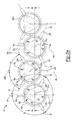
- FIG. 2 is a cross-sectional view of the opposed-piston engine of FIG. 1 ;
- FIG. 3A is another cross-sectional view of the opposed-piston engine of FIG. 1 ;
- FIG. 3B is a cross-sectional view of another opposed piston engine in accordance with the principles of the present disclosure.
- FIG. 4A is a side elevation view of an example piston of the opposed-piston engine of FIG. 1 ;
- FIG. 4B is a side elevation view of another example piston of the opposed-piston engine of FIG. 1 .
- an engine 10 is provided.
- the engine 10 may be an opposed-piston, two-stroke diesel engine for use in a vehicle or other machine. It will be appreciated, however, that the engine 10 may have other configurations such as a spark-ignition engine or a free-piston engine within the scope of the present disclosure.
- the engine 10 may include a housing or cylinder 14 , one or more piston 16 , an outlet 18 , an inlet 20 , and at least one fuel injector or nozzle 22 .
- a housing or cylinder 14 may include one or more piston 16 , an outlet 18 , an inlet 20 , and at least one fuel injector or nozzle 22 .
- the engine 10 may include any number of cylinders 14 , each including at least one piston 16 , as is known in the art.
- the engine 10 may include two pistons 16 .
- the cylinder 14 may be formed from a material such as iron, steel, or a suitable metallic alloy, and may extend along a longitudinal axis A 1 .
- the longitudinal axis A 1 may be a central longitudinal axis A 1 , such that the cylinder 14 is symmetrically disposed about the longitudinal axis A 1 .
- the cylinder 14 may also include a transverse axis A 2 extending in a direction substantially perpendicular to the longitudinal axis A 1 .
- a bore or passage 26 may extend through, or otherwise be defined by, the cylinder 14 along the longitudinal axis A 1 .
- the outlet 18 and the inlet 20 may be configured to fluidly communicate with the passage 26 .
- the inlet 20 can be configured to deliver air (e.g., ambient air, air from a turbocharger or other portion of an exhaust gas regeneration system (not shown), etc.) to the passage 26 for combustion, while the outlet 18 can be configured to remove exhaust gases from the passage 26 after combustion.
- air e.g., ambient air, air from a turbocharger or other portion of an exhaust gas regeneration system (not shown), etc.
- the pistons 16 may be slidably disposed in the passage 26 of the cylinder 14 for opposed, reciprocating motion along the longitudinal axis A 1 .
- Each piston 16 may include a skirt 28 and a crown 30 .
- the skirt 28 can be integrally or monolithically formed with the crown 30 .
- the crown 30 may include a recess 32 that is at least partially formed or defined by a bottom surface 34 , first side surface 36 , a second side surface 38 , and a third side surface 40 .
- the bottom surface 34 may be concave and symmetrically disposed about the longitudinal axis A 1 .
- the first, second, and third side surfaces 36 , 38 , 40 may be substantially identical to each other.
- first, second, and third side surfaces 36 , 38 , 40 may extend from an end or rim 42 of the piston 16 to the bottom surface 34 . Accordingly, the first, second, and third side surfaces 36 , 38 , 40 may be symmetrically disposed about the longitudinal axis A 1 . In some configurations, the first, second, and third side surfaces 36 , 38 , 40 may include a concave shape or profile. It will be appreciated, however, that the first, second, and third side surfaces 36 , 38 , 40 may include various shapes or profiles within the scope of the present disclosure.
- the recess 32 of a first piston 16 a and the recess 32 of a second piston 16 b may define a chamber 50 therebetween.
- the first and second pistons 16 a , 16 b may be disposed within the passage 26 such that the first, second, and third side surfaces 36 , 38 , 40 of the first piston 16 a are aligned with the first, second, and third side surfaces 36 , 38 , 40 , respectively, of the second piston 16 b .
- the chamber 50 may be symmetrically disposed relative to the longitudinal axis A 1 .
- the chamber 50 may be symmetric relative to a cross section of the engine 10 intersecting the longitudinal axis A 2 ( FIG.
- first, second, and third side surfaces 36 , 38 , 40 of the first piston 16 a may be offset from, or otherwise have a different shape or profile than the first, second, and third side surfaces 36 , 38 , 40 of the second piston 16 b , such that the chamber 50 may be asymmetric relative to the cross section of the engine 10 intersecting the longitudinal axis A 1 ( FIG. 2 ), and/or asymmetric relative to the cross section of the engine 10 intersecting the transverse axis A 2 ( FIG. 2 ).
- the first piston 16 a of a first cylinder 14 a may be angularly offset relative to the orientation of the first piston 16 a of a second cylinder 14 b .
- the first piston 16 a of a third cylinder 14 c may be angularly offset relative to the orientation of the first piston 16 a of the second cylinder 14 b .
- first piston 16 a of the second cylinder 14 b may be rotated by a first angle about the longitudinal axis A 1 b relative to the orientation of the first piston 16 a of the first cylinder 14 a about the longitudinal axis A 1 a
- first piston 16 a of the third cylinder 14 c may be rotated by a second angle about the longitudinal axis A 1 c relative to the orientation of the first piston 16 a of the second cylinder 14 b about the longitudinal axis A 1 b .
- the first angle may be substantially equal to the second angle, such that the first piston 16 a of the first cylinder 14 a is substantially angularly aligned with the first piston 16 a of the third cylinder 14 c relative to, or about, the longitudinal axes A 1 a and A 1 c .
- the second pistons 16 b of the first, second, and third cylinders 14 a , 14 b , 14 c may also be angularly offset from one another as described above with respect to the first pistons 16 a.
- each piston 16 may be supported by, or otherwise coupled to, a connecting rod 54 .
- the connecting rod 54 can be supported by, or otherwise coupled to, a crankshaft (not shown).
- the nozzle 22 can be disposed within, or otherwise extend through, the cylinder 14 .
- the cylinder 14 may include three nozzles 22 disposed within the cylinder 14 about the longitudinal axis A 1 , such that each nozzle 22 is offset from an adjacent nozzle 22 by an angle ⁇ about the longitudinal axis A 1 .
- a first nozzle 22 a may extend from the cylinder 14 along an axis Xa
- a second nozzle 22 b may extend from the cylinder along an axis Xb
- a third nozzle 22 c may extend from the cylinder along an axis Xc.
- the axis Xa may be offset from the axis Xb by an angle ⁇ a
- the axis Xb may be offset from the axis Xc by an angle ⁇ b
- the axis Xc may be offset from the axis Xa by an angle ⁇ c.
- the angle ⁇ a may be substantially equal to the angle ⁇ b
- the angle ⁇ b may be substantially equal to the angle ⁇ c, such that the nozzles 22 a , 22 b and 22 c are symmetrically disposed about the longitudinal axis A 1 .
- the first nozzle 22 a may be disposed or otherwise aligned with a point of intersection of the first and second surfaces 36 , 38 of the first piston 16 a
- the second nozzle 22 b may be disposed or otherwise aligned with a point of intersection of the second and third surfaces 38 , 40 of the first piston 16 a
- the third nozzle 22 c may be disposed or otherwise aligned with a point of intersection of the first and third surfaces 36 , 40 of the first piston 16 a
- ⁇ a, ⁇ b, and ⁇ c may each be equal to an angle between 100 degrees and 140 degrees.
- ⁇ a, ⁇ b, and ⁇ c may each be equal to 120 degrees. It will also be appreciated that the angle ⁇ a may differ from the angle ⁇ b, and/or the angle ⁇ b may differ from the angle ⁇ c.
- the nozzles 22 may be in fluid communication with the passage 26 .
- the nozzles 22 can be configured to spray or otherwise deliver a volume of fuel to the chamber 50 for combustion.
- the nozzles 22 may be aligned relative to the longitudinal axis A 1 .
- the nozzles 22 a , 22 b , 22 c may deliver the volume of fuel in a direction substantially along or parallel to the axes Xa, Xb, Xc, respectively.
- the volume of fuel may be delivered in a direction that is offset from the axes Xa, Xb, Xc.
- the cylinders 14 may be positioned within the engine 10 such that the longitudinal axes A 1 are substantially parallel to each other.
- cylinders 14 may be positioned within the engine such that the nozzles 22 of the first cylinder 14 a are aligned with the nozzles 22 of the second and/or third cylinders 14 b , 14 c relative to the longitudinal axes A 1 b , A 1 c , respectively.
- the axes Xa, Xb, Xc of the nozzles 22 of one or more of the cylinders 14 may extend in, or otherwise define, a plane.
- all of the axes Xa, Xb, Xc of the nozzles 22 of the cylinders 14 may extend in, or otherwise define, a plane.
- the longitudinal axis A 1 a of the first cylinder 14 a may also be offset from the longitudinal axis A 1 b of the second cylinder 14 b that is adjacent to the first cylinder 14 a .
- the longitudinal axis A 1 b may be offset in a first direction from the longitudinal axis A 1 a by a distance Da.
- the longitudinal axis A 1 c of the third cylinder 14 c may be offset in a second direction from the longitudinal axis A 1 b by a distance Db.
- the second direction may be opposite the first direction.
- the distance Db may be substantially equal to the distance Da, such that the longitudinal axis A 1 c is aligned or otherwise coplanar with the longitudinal axis A 1 b .
- the engine 10 may include any number (N) of cylinders 14 .
- each cylinder 14 (N) may be offset from an adjacent cylinder 14 (N ⁇ 1) by the distance Da, and offset from an adjacent cylinder 14 (N+1) by the distance Db.
- the nozzles 22 a , 22 b , 22 c of the first cylinder 14 a may also be angularly offset about the longitudinal axis A 1 a relative to the nozzles 22 a , 22 b , 22 c , respectively, of the second cylinder 14 b .
- the first nozzle 22 a of the second cylinder 14 b may be angularly offset about the longitudinal axis A 1 b relative to the orientation of the first nozzle 22 a of the first cylinder 14 a about the longitudinal axis A 1 a .
- the axis Xa of the first nozzle 22 a of the first cylinder 14 a may be substantially aligned with the transverse axis A 2 a of the first cylinder 14 a
- the axis Xa of the first nozzle 22 a of the second cylinder 14 b may be offset from the transverse axis A 2 b of the second cylinder 14 b by an angle ⁇ b.
- the axis Xb of the second nozzle 22 b of the first cylinder 14 a may be offset from the transverse axis A 2 a of the first cylinder 14 a by the angle ⁇ a, while the axis Xb of the second nozzle 22 b of the second cylinder 14 b may be substantially aligned with the transverse axis A 2 b of the second cylinder 14 b .
- the axis Xc of the third nozzle 22 c of the first cylinder 14 a may be offset from the transverse axis A 2 a of the first cylinder 14 a by the angle ⁇ c
- the axis Xc of the third nozzle 22 c of the second cylinder 14 b may be offset from the transverse axis A 2 b of the second cylinder 14 b by an angle ⁇ c.
- the angles ⁇ a, ⁇ b, and ⁇ c may be substantially equal to each other.
- the axis Xa of the first nozzle 22 a of the first cylinder 14 a may be offset from the axis Xa of the first nozzle 22 a of the second cylinder 14 b by an angle between 45 and 75 degrees, and in some configurations, substantially equal to 60 degrees.
- the axes Xb, Xc of the second and third nozzles 22 b , 22 c of the first cylinder 14 a may be offset from the axes Xb, Xc, respectively, of the second and third nozzles 22 b , 22 c of the second cylinder 14 b by an angle between 45 and 75 degrees, and in some configurations, substantially equal to 60 degrees.
- the configuration of the cylinders 14 can allow for the closest possible arrangement of the cylinders 14 within the engine 10 having three nozzles 22 .
- arranging the cylinders 14 and the nozzles 22 a , 22 b , 22 c in the manner described can help to prevent the nozzles 22 a , 22 b , 22 c from contacting or otherwise interfering with an adjacent cylinder 14 and/or the nozzles 22 a , 22 b , 22 c of the adjacent cylinder 14 , thus allowing for a reduction in the size of the engine 10 .
- the inclusion of three nozzles 22 within the engine 10 can help to ensure improved combustion performance, including efficient utilization and combustion of air within the chamber 50 , as well as the efficient mixing of fuel from each of the nozzles 22 within the chamber 50 .
- FIG. 3B another example of an engine is labelled 10 a .
- the engine 10 a is substantially similar to the engine 10 such that only differences between the engines 10 , 10 a will now be described.
- the longitudinal axis A 1 b of the second cylinder 14 b is offset in a first direction from the longitudinal axis A 1 a of the first cylinder 14 a .
- the longitudinal axis A 1 c of the third cylinder 14 c is offset in a second direction from the longitudinal axis A 1 b , where the second direction is opposite from the first direction.
- the longitudinal axes A 1 a , A 1 b , A 1 c , of the first, second, and third cylinders 14 a , 14 b , and 14 c are aligned with one another such that the longitudinal axes A 1 a , A 1 b , A 1 c all lie within the same plane.
- the angles ⁇ a, ⁇ b, and ⁇ c between the axes Xa, Xb, Xc of the nozzles 22 a , 22 b , 22 c are each equal to 120 degrees.
- the nozzles 22 a , 22 b , 22 c are symmetrically disposed about the longitudinal axes A 1 a , A 1 b , A 1 c of the first, second, and third cylinders 14 a , 14 b , and 14 c .
- the angle ⁇ a between the first and second nozzles 22 a and 22 b is less than the angle ⁇ b between the second and third nozzles 22 a and 22 b and less than the angle ⁇ c between the first and third nozzles 22 a and 22 c .
- the angles ⁇ b and ⁇ c are equal to each other such that the distal ends of the nozzles 22 a , 22 b , 22 c form an isosceles triangle 53 .
- the angle ⁇ a is between 60 degrees and 120 degrees (e.g., 70 degrees), and each of the angles ⁇ b and ⁇ c are between 150 degrees and 120 degrees (e.g., 145 degrees).
- each of the angles ⁇ b and ⁇ c may be determined by subtracting the angle ⁇ a from 360 degrees and dividing the result by two.
- the shape of the crown 30 of the pistons 16 in the engine 10 a is different than the shape of the crown 30 of the pistons 16 in the engine 10 .
- the first, second, and third side surfaces 36 , 38 , and 40 of the recess 32 are disposed adjacent to the first, second, and third nozzles 22 a , 22 b , and 22 c , respectively.
- first, second, and third side surfaces 36 , 38 , and 40 have elongated, concave shapes that are centered about the axis Xa, Xb, or Xc of a corresponding one of the first, second, and third nozzles 22 a , 22 b , and 22 c .
- the shapes of the first, second, and third side surfaces 36 , 38 , and 40 accommodate the spray patterns of the first, second, and third nozzles 22 a , 22 b , and 22 c , respectively.
- the bottom surface 34 of the recess 32 has a hemispherical, concave shape that provides fluid communication between the elongated, concave shapes formed by the first, second, and third side surfaces 36 , 38 , and 40 .
- FIG. 4B another example of one of the pistons 16 of the engine 10 or 10 a is shown.
- the crown 30 of the piston 16 may not be flat.
- the recess 32 may be inset or depressed in the crown 30 of the piston 16 relative to the rim 42 of the piston 16 .
- the piston 16 includes one or more piston rings 56 that extend annularly about the piston 16 .
- Each of the piston rings 56 defines a ring plane 58 , which may be transverse to the skirt 28 .
- the piston rings 56 abut and seal against the cylinder 14 (see FIG. 1 ) to prevent the blow-by of combustion gases. Limiting the operational temperatures of the piston rings 56 to avoid ring failure is critical to the design of the engine 10 . Overheating of the piston rings 56 , and ultimately ring failure, can be caused by combustion related heat and/or heat generated by friction between the piston rings 56 and the cylinder 14 .
- the piston 16 may be provided with a cooling gallery 60 that functions to draw heat away from the piston rings 56 .
- the cooling gallery 60 may have an annular shape and may be disposed within the piston 16 inwardly of the crown 30 .
- the cooling gallery 60 is hollow and may include openings 62 that allow oil within passage 26 (see FIG. 1 ) to enter and exit the cooling gallery 60 in order to carry heat away from the crown 30 .
- improved thermal management (i.e. cooling) of the piston 16 may be achieved.
- the piston 16 may be coated with a ceramic material 64 for improved heat resistance.
- the piston 16 itself may be made of a variety of different materials.
- the piston 16 may be made of a steel alloy, an aluminum alloy, or cast iron. These materials are generally good thermal conductors such that the heat experienced by the crown 30 is transferred through the piston 16 and to the piston rings 56 .
- the ceramic material 64 coating the piston 16 reduces heat transfer between hot combustion gases in the chamber 50 (see FIG. 2 ) and the crown 30 of the piston 16 and therefore reduces the amount of heat that is transferred from the piston 16 to the piston rings 56 .
- the ceramic material 64 coating the piston 16 helps insulate the piston 16 from hot combustion gases and therefore reduces the temperature of the piston 16 . Because the piston 16 is kept at a lower temperature as a result of the ceramic material 64 , the amount of heat that is transferred from the piston 16 to the piston rings 56 is reduced. This ultimately lowers the operating temperature of the piston rings 56 .
- the ceramic material 64 coating the piston 16 may be applied using known manufacturing techniques.
- a thermal cap 66 of the crown 30 may be formed separate from a base 68 of the crown 30 and secured to or retained on the base 68 .
- the thermal cap 66 can be made of the ceramic material, and the base 68 can be made of a metal material.
- FIG. 4B the thermal cap 66 is shown separated from the base 68 and slightly tilted with respect to the base 68 in a direction D 1 about a transverse axis T 1 .
- the thermal cap 66 may be retained on the base 68 in a variety of different ways.
- the thermal cap 66 may be retained on the base 68 by a mechanical connection, friction welding, thermal welding, or by an adhesive.
- the thermal cap 66 defines the top surface of the crown 30 of the piston 16 shown in FIG. 4B .
- the thermal cap 66 helps insulate the piston 16 from hot combustion gases within the chamber 50 . Again, this decreases operational temperatures at the piston rings 56 , which leads to improved piston ring function and increased service life.
- the thermal cap 66 may be used in place of or in addition to the cooling gallery 60 .
- the strength of the piston 16 is not compromised because the hollow cooling gallery 60 and the associated stress risers that the cooling gallery 60 creates in the piston 16 are eliminated.
- the piston 16 is more resistant to deflection caused by operational forces, including forces resulting from combustion, friction, inertia, and thermal expansion of the piston 16 , the piston rings 16 , and/or the cylinder 14 .
- the piston 16 may be made without complex machining operations, reducing manufacturing time and costs.
- the example piston 16 shown in FIG. 4A includes the piston rings 56 described with reference to the example piston 16 shown in FIG. 4B .
- the example piston 16 shown in FIGS. 1, 2, and 3A may incorporate various features described with reference to the example piston 16 shown in FIG. 4B .
- the example piston 16 shown in FIGS. 1, 2, and 3A may be provided with the cooling gallery 60 , may be coated with the ceramic material 64 , and/or may include the thermal cap 66 formed separate from and joined to the base 68 .
- Example embodiments are provided so that this disclosure will be thorough, and will fully convey the scope to those who are skilled in the art. Numerous specific details are set forth such as examples of specific components, devices, and methods, to provide a thorough understanding of embodiments of the present disclosure. It will be apparent to those skilled in the art that specific details need not be employed, that example embodiments may be embodied in many different forms and that neither should be construed to limit the scope of the disclosure. In some example embodiments, well-known processes, well-known device structures, and well-known technologies are not described in detail.
- first, second, third, etc. may be used herein to describe various elements, components, regions, layers and/or sections, these elements, components, regions, layers and/or sections should not be limited by these terms. These terms may be only used to distinguish one element, component, region, layer or section from another region, layer or section. Terms such as “first,” “second,” and other numerical terms when used herein do not imply a sequence or order unless clearly indicated by the context. Thus, a first element, component, region, layer or section discussed below could be termed a second element, component, region, layer or section without departing from the teachings of the example embodiments.
- Spatially relative terms such as “inner,” “outer,” “beneath,” “below,” “lower,” “above,” “upper,” and the like, may be used herein for ease of description to describe one element or feature's relationship to another element(s) or feature(s) as illustrated in the figures. Spatially relative terms may be intended to encompass different orientations of the device in use or operation in addition to the orientation depicted in the figures. For example, if the device in the figures is turned over, elements described as “below” or “beneath” other elements or features would then be oriented “above” the other elements or features. Thus, the example term “below” can encompass both an orientation of above and below. The device may be otherwise oriented (rotated 90 degrees or at other orientations) and the spatially relative descriptors used herein interpreted accordingly.
Landscapes
- Engineering & Computer Science (AREA)
- Mechanical Engineering (AREA)
- General Engineering & Computer Science (AREA)
- Chemical & Material Sciences (AREA)
- Combustion & Propulsion (AREA)
- Combustion Methods Of Internal-Combustion Engines (AREA)
- Fuel-Injection Apparatus (AREA)
Abstract
Description
Claims (27)
Priority Applications (2)
| Application Number | Priority Date | Filing Date | Title |
|---|---|---|---|
| US15/050,878 US10066590B2 (en) | 2015-02-27 | 2016-02-23 | Opposed piston three nozzle combustion chamber design |
| EP16157545.1A EP3061906B1 (en) | 2015-02-27 | 2016-02-26 | Opposed piston three nozzle combustion chamber design |
Applications Claiming Priority (5)
| Application Number | Priority Date | Filing Date | Title |
|---|---|---|---|
| US201562126009P | 2015-02-27 | 2015-02-27 | |
| US201562121879P | 2015-02-27 | 2015-02-27 | |
| US201562121815P | 2015-02-27 | 2015-02-27 | |
| US201562121788P | 2015-02-27 | 2015-02-27 | |
| US15/050,878 US10066590B2 (en) | 2015-02-27 | 2016-02-23 | Opposed piston three nozzle combustion chamber design |
Publications (2)
| Publication Number | Publication Date |
|---|---|
| US20160252065A1 US20160252065A1 (en) | 2016-09-01 |
| US10066590B2 true US10066590B2 (en) | 2018-09-04 |
Family
ID=55650045
Family Applications (1)
| Application Number | Title | Priority Date | Filing Date |
|---|---|---|---|
| US15/050,878 Active 2036-09-28 US10066590B2 (en) | 2015-02-27 | 2016-02-23 | Opposed piston three nozzle combustion chamber design |
Country Status (2)
| Country | Link |
|---|---|
| US (1) | US10066590B2 (en) |
| EP (1) | EP3061906B1 (en) |
Families Citing this family (3)
| Publication number | Priority date | Publication date | Assignee | Title |
|---|---|---|---|---|
| US10724467B2 (en) | 2016-11-04 | 2020-07-28 | Cummins Inc. | Pistons with thermal barrier coatings |
| US10731259B2 (en) * | 2016-11-04 | 2020-08-04 | Cummins Inc. | Pistons with thermal barrier coatings |
| CN109339946A (en) * | 2018-11-15 | 2019-02-15 | 北京理工大学 | A kind of double-crankshaft opposed pistons four-stroke engine based on valve scavenging |
Citations (60)
| Publication number | Priority date | Publication date | Assignee | Title |
|---|---|---|---|---|
| US1127772A (en) * | 1913-01-02 | 1915-02-09 | Hugo Junkers | Internal-combustion engine. |
| US1143408A (en) * | 1913-01-18 | 1915-06-15 | Gen Electric | Internal-combustion engine. |
| US1486583A (en) | 1923-01-26 | 1924-03-11 | William M Huskisson | Internal-combustion engine |
| US2463418A (en) | 1942-04-30 | 1949-03-01 | Pescara Raul Pateras | Fuel injection system |
| US3007462A (en) * | 1957-08-26 | 1961-11-07 | Vernon W Balzer | Reciprocating machine |
| GB1014831A (en) | 1961-06-26 | 1965-12-31 | James Abraham Hardman | Improvements in or relating to internal combustion engines |
| US3407790A (en) | 1967-04-12 | 1968-10-29 | Anker K. Antonsen | Uniflow scavenged engine having improved gaseous fuel admission |
| FR2145081A5 (en) | 1971-07-08 | 1973-02-16 | Peugeot & Renault | |
| US3997117A (en) | 1975-01-09 | 1976-12-14 | Klockner-Humboldt-Deutz Aktiengesellschaft | Fuel injection valve for internal combustion engines |
| US4043301A (en) | 1975-06-20 | 1977-08-23 | Templet Industries Incorporated | Internal combustion engine |
| GB2019487A (en) | 1978-04-25 | 1979-10-31 | Renegar C G | Internal Combustion Engine with Opposed Guided Pistons and Cam Drives |
| EP0196265A2 (en) | 1985-03-25 | 1986-10-01 | Stanadyne Inc. | Modular accumulator injector |
| US4872433A (en) * | 1987-12-07 | 1989-10-10 | Paul Marius A | Combustion chamber configurations for two cycle engines |
| US5042441A (en) * | 1989-10-03 | 1991-08-27 | Paul Marius A | Low emission combustion system for internal combustion engines |
| EP0836003A1 (en) | 1996-10-11 | 1998-04-15 | IVECO FIAT S.p.A. | Fuel injector for a heat engine and a heat engine provided with such an injector |
| US6170443B1 (en) | 1998-09-11 | 2001-01-09 | Edward Mayer Halimi | Internal combustion engine with a single crankshaft and having opposed cylinders with opposed pistons |
| WO2001025618A1 (en) | 1999-10-04 | 2001-04-12 | Cosimo Sarno | Multi-injection systems |
| US20020109014A1 (en) | 1999-08-10 | 2002-08-15 | Ulrich Augustin | Control valve configuration for use in a fuel injector for internal combustion engines |
| US20030101967A1 (en) | 2001-12-04 | 2003-06-05 | Forck Glen F. | Compact valve assembly and fuel injector using same |
| US20040139932A1 (en) * | 2000-10-03 | 2004-07-22 | Palmer Dennis C. | Internal combustion engine |
| US20060157003A1 (en) | 2004-06-10 | 2006-07-20 | Lemke James U | Opposed piston engine |
| US7334570B2 (en) | 2005-04-01 | 2008-02-26 | Achates Power, Inc. | Common rail fuel injection system with accumulator injectors |
| JP2009103085A (en) | 2007-10-25 | 2009-05-14 | Suzuki Motor Corp | Fuel injection control device of two-cycle engine |
| DE102007056913A1 (en) | 2007-11-26 | 2009-05-28 | Robert Bosch Gmbh | Injector for fuel with ball valve |
| US20100252010A1 (en) | 2009-04-07 | 2010-10-07 | Ford Allen Phillips | Crescent-Shaped Recess in Piston of a Split-Cycle Engine |
| JP4576884B2 (en) | 2004-05-19 | 2010-11-10 | トヨタ自動車株式会社 | Control device and control method for internal combustion engine |
| WO2011061191A1 (en) | 2009-11-18 | 2011-05-26 | Otto Daude | Fuel injection method for diesel engines with injection nozzles arranged in a tangential manner on the periphery of the cylinder |
| US20120080007A1 (en) | 2010-05-18 | 2012-04-05 | Achates Power, Inc. | Fuel injector support constructions for direct injection opposed-piston engines |
| CN102588075A (en) | 2012-03-13 | 2012-07-18 | 深圳市世纪经纬数据系统有限公司 | Cylinder internal multi-point injection internal combustion engine |
| US20120192831A1 (en) | 2011-01-27 | 2012-08-02 | Ecomotors International, Inc. | Combustion Chamber for a Side-Mounted Direction Injector |
| WO2012143075A1 (en) | 2011-04-20 | 2012-10-26 | Daimler Ag | Piston for a reciprocating internal combustion engine |
| WO2012158756A1 (en) | 2011-05-18 | 2012-11-22 | Achates Power, Inc. | Combustion chamber construction for opposed-piston engines |
| GB2491155A (en) | 2011-05-24 | 2012-11-28 | Cox Powertrain Ltd | Opposed piston combustion engine having fuel injector disposed at least partly within an engine cylinder |
| US20130014718A1 (en) | 2011-07-15 | 2013-01-17 | Ecomotors International, Inc. | Toroidal Combustion Chamber With Side Injection |
| GB2493260A (en) | 2011-07-26 | 2013-01-30 | Ecomotors Internat Inc | Opposed piston engine with tumble flow in shaped combustion chamber |
| US20130036999A1 (en) | 2011-08-08 | 2013-02-14 | Ecomotors International, Inc. | High-Squish Combustion Chamber With Side Injection |
| US20130104848A1 (en) | 2011-10-27 | 2013-05-02 | Achates Power, Inc. | Fuel Injection Strategies in Opposed-Piston Engines with Multiple Fuel Injectors |
| US20130146021A1 (en) | 2011-12-09 | 2013-06-13 | Ecomotors, Inc. | Toroidal Combustion Chamber With Side Injection |
| US20130152547A1 (en) | 2011-12-15 | 2013-06-20 | Ecomotors, Inc. | Toroidal Combustion Chamber With Side Injection |
| US20130213342A1 (en) | 2010-04-27 | 2013-08-22 | Achates Power, Inc. | Piston Crown Bowls Defining Combustion Chamber Constructions In Opposed-Piston Engines |
| US20130276762A1 (en) | 2012-04-18 | 2013-10-24 | Ecomotors, Inc. | Symmetric Opposed-Piston, Opposed-Cylinder Engine |
| EP2672101A1 (en) | 2012-06-05 | 2013-12-11 | Caterpillar Motoren GmbH & Co. KG | Injection nozzle |
| WO2014000946A1 (en) | 2012-06-27 | 2014-01-03 | Robert Bosch Gmbh | Method for controlling an internal combustion engine, and a system comprising an internal combustion engine and a control device |
| US20140014063A1 (en) | 2010-04-27 | 2014-01-16 | Achates Power, Inc. | Swirl-Conserving Combustion Chamber Construction For Opposed-Piston Engines |
| US20140026840A1 (en) | 2012-07-27 | 2014-01-30 | Honda Motor Co., Ltd | Piston structure for internal combustion engine |
| WO2014030319A1 (en) | 2012-08-24 | 2014-02-27 | マツダ株式会社 | Engine combustion chamber structure |
| US8689768B2 (en) | 2010-09-22 | 2014-04-08 | Hitachi Automotive Systems, Ltd. | Apparatus and method for controlling fuel injection of internal combustion engine |
| WO2014096956A1 (en) | 2012-12-21 | 2014-06-26 | Toyota Jidosha Kabushiki Kaisha | Piston of internal combustion engine and internal combustion engine provided therewith |
| US8800528B2 (en) | 2010-04-27 | 2014-08-12 | Achates Power, Inc. | Combustion chamber constructions for opposed-piston engines |
| US8820294B2 (en) * | 2010-08-16 | 2014-09-02 | Achates Power, Inc. | Fuel injection spray patterns for opposed-piston engines |
| WO2014162143A1 (en) | 2013-04-05 | 2014-10-09 | Osp Engines Limited | Opposed piston engine and lubrication system |
| EP2837802A1 (en) | 2012-04-11 | 2015-02-18 | Mitsubishi Heavy Industries, Ltd. | Dual-fuel diesel engine |
| US20150285127A1 (en) * | 2012-09-25 | 2015-10-08 | Achates Power, Inc. | Fuel injection with swirl spray patterns in opposed-piston engines |
| US9211797B2 (en) | 2013-11-07 | 2015-12-15 | Achates Power, Inc. | Combustion chamber construction with dual mixing regions for opposed-piston engines |
| US20150377169A1 (en) | 2014-06-30 | 2015-12-31 | Mitsubishi Jidosha Kogyo Kabushiki Kaisha | Fuel injection control apparatus |
| US20160032823A1 (en) * | 2014-08-01 | 2016-02-04 | Avl Powertrain Engineering, Inc. | Cylinder arrangement for opposed piston two-stroke engine |
| US20160032859A1 (en) | 2014-08-04 | 2016-02-04 | General Electric Company | System and method for controlling operation of an engine |
| GB2530761A (en) | 2014-10-01 | 2016-04-06 | Delphi Internat Operations Luxembourg S Ã R L | Fuel injection equipment |
| US20160195028A1 (en) * | 2013-08-05 | 2016-07-07 | Achates Power, Inc. | Dual-fuel constructions for opposed-piston engines with shaped combustion chambers |
| US20160252067A1 (en) * | 2015-02-27 | 2016-09-01 | Avl Powertrain Engineering, Inc. | Opposed Piston Three Nozzle Piston Bowl Design |
-
2016
- 2016-02-23 US US15/050,878 patent/US10066590B2/en active Active
- 2016-02-26 EP EP16157545.1A patent/EP3061906B1/en active Active
Patent Citations (68)
| Publication number | Priority date | Publication date | Assignee | Title |
|---|---|---|---|---|
| US1127772A (en) * | 1913-01-02 | 1915-02-09 | Hugo Junkers | Internal-combustion engine. |
| US1143408A (en) * | 1913-01-18 | 1915-06-15 | Gen Electric | Internal-combustion engine. |
| US1486583A (en) | 1923-01-26 | 1924-03-11 | William M Huskisson | Internal-combustion engine |
| US2463418A (en) | 1942-04-30 | 1949-03-01 | Pescara Raul Pateras | Fuel injection system |
| US3007462A (en) * | 1957-08-26 | 1961-11-07 | Vernon W Balzer | Reciprocating machine |
| GB1014831A (en) | 1961-06-26 | 1965-12-31 | James Abraham Hardman | Improvements in or relating to internal combustion engines |
| US3407790A (en) | 1967-04-12 | 1968-10-29 | Anker K. Antonsen | Uniflow scavenged engine having improved gaseous fuel admission |
| US3777977A (en) | 1971-07-08 | 1973-12-11 | Peugeot | Injection device |
| FR2145081A5 (en) | 1971-07-08 | 1973-02-16 | Peugeot & Renault | |
| US3997117A (en) | 1975-01-09 | 1976-12-14 | Klockner-Humboldt-Deutz Aktiengesellschaft | Fuel injection valve for internal combustion engines |
| US4043301A (en) | 1975-06-20 | 1977-08-23 | Templet Industries Incorporated | Internal combustion engine |
| GB2019487A (en) | 1978-04-25 | 1979-10-31 | Renegar C G | Internal Combustion Engine with Opposed Guided Pistons and Cam Drives |
| EP0196265A2 (en) | 1985-03-25 | 1986-10-01 | Stanadyne Inc. | Modular accumulator injector |
| US4872433A (en) * | 1987-12-07 | 1989-10-10 | Paul Marius A | Combustion chamber configurations for two cycle engines |
| US5042441A (en) * | 1989-10-03 | 1991-08-27 | Paul Marius A | Low emission combustion system for internal combustion engines |
| EP0836003A1 (en) | 1996-10-11 | 1998-04-15 | IVECO FIAT S.p.A. | Fuel injector for a heat engine and a heat engine provided with such an injector |
| US6170443B1 (en) | 1998-09-11 | 2001-01-09 | Edward Mayer Halimi | Internal combustion engine with a single crankshaft and having opposed cylinders with opposed pistons |
| US20020109014A1 (en) | 1999-08-10 | 2002-08-15 | Ulrich Augustin | Control valve configuration for use in a fuel injector for internal combustion engines |
| WO2001025618A1 (en) | 1999-10-04 | 2001-04-12 | Cosimo Sarno | Multi-injection systems |
| US20040139932A1 (en) * | 2000-10-03 | 2004-07-22 | Palmer Dennis C. | Internal combustion engine |
| US20030101967A1 (en) | 2001-12-04 | 2003-06-05 | Forck Glen F. | Compact valve assembly and fuel injector using same |
| JP4576884B2 (en) | 2004-05-19 | 2010-11-10 | トヨタ自動車株式会社 | Control device and control method for internal combustion engine |
| US20060157003A1 (en) | 2004-06-10 | 2006-07-20 | Lemke James U | Opposed piston engine |
| US7334570B2 (en) | 2005-04-01 | 2008-02-26 | Achates Power, Inc. | Common rail fuel injection system with accumulator injectors |
| JP2009103085A (en) | 2007-10-25 | 2009-05-14 | Suzuki Motor Corp | Fuel injection control device of two-cycle engine |
| DE102007056913A1 (en) | 2007-11-26 | 2009-05-28 | Robert Bosch Gmbh | Injector for fuel with ball valve |
| US20100252010A1 (en) | 2009-04-07 | 2010-10-07 | Ford Allen Phillips | Crescent-Shaped Recess in Piston of a Split-Cycle Engine |
| US20120285418A1 (en) * | 2009-11-18 | 2012-11-15 | Elsbett Gueenter | Fuel injection method for diesel engines with injection nozzles arranged in a tangential manner on the periphery of the cylinder |
| WO2011061191A1 (en) | 2009-11-18 | 2011-05-26 | Otto Daude | Fuel injection method for diesel engines with injection nozzles arranged in a tangential manner on the periphery of the cylinder |
| US20150013649A1 (en) | 2010-04-27 | 2015-01-15 | Achates Power, Inc. | Combustion Chamber Constructions For Opposed-Piston Engines |
| US20130213342A1 (en) | 2010-04-27 | 2013-08-22 | Achates Power, Inc. | Piston Crown Bowls Defining Combustion Chamber Constructions In Opposed-Piston Engines |
| US8800528B2 (en) | 2010-04-27 | 2014-08-12 | Achates Power, Inc. | Combustion chamber constructions for opposed-piston engines |
| US20140014063A1 (en) | 2010-04-27 | 2014-01-16 | Achates Power, Inc. | Swirl-Conserving Combustion Chamber Construction For Opposed-Piston Engines |
| US8997710B2 (en) | 2010-05-18 | 2015-04-07 | Achates Power, Inc. | Fuel injector support constructions for direct injection opposed-piston engines |
| US20120080007A1 (en) | 2010-05-18 | 2012-04-05 | Achates Power, Inc. | Fuel injector support constructions for direct injection opposed-piston engines |
| US8820294B2 (en) * | 2010-08-16 | 2014-09-02 | Achates Power, Inc. | Fuel injection spray patterns for opposed-piston engines |
| US8689768B2 (en) | 2010-09-22 | 2014-04-08 | Hitachi Automotive Systems, Ltd. | Apparatus and method for controlling fuel injection of internal combustion engine |
| US20120192831A1 (en) | 2011-01-27 | 2012-08-02 | Ecomotors International, Inc. | Combustion Chamber for a Side-Mounted Direction Injector |
| WO2012143075A1 (en) | 2011-04-20 | 2012-10-26 | Daimler Ag | Piston for a reciprocating internal combustion engine |
| WO2012158756A1 (en) | 2011-05-18 | 2012-11-22 | Achates Power, Inc. | Combustion chamber construction for opposed-piston engines |
| GB2491155A (en) | 2011-05-24 | 2012-11-28 | Cox Powertrain Ltd | Opposed piston combustion engine having fuel injector disposed at least partly within an engine cylinder |
| US8783218B2 (en) * | 2011-07-15 | 2014-07-22 | EcoMotors International | Toroidal combustion chamber with side injection |
| US20130014718A1 (en) | 2011-07-15 | 2013-01-17 | Ecomotors International, Inc. | Toroidal Combustion Chamber With Side Injection |
| US8677950B2 (en) | 2011-07-26 | 2014-03-25 | Ecomotors, Inc. | Combustion chamber promoting tumble flow |
| GB2493260A (en) | 2011-07-26 | 2013-01-30 | Ecomotors Internat Inc | Opposed piston engine with tumble flow in shaped combustion chamber |
| US20130025556A1 (en) | 2011-07-26 | 2013-01-31 | Ecomotors International, Inc. | Combustion Chamber Promoting Tumble Flow |
| US20130036999A1 (en) | 2011-08-08 | 2013-02-14 | Ecomotors International, Inc. | High-Squish Combustion Chamber With Side Injection |
| US20130104848A1 (en) | 2011-10-27 | 2013-05-02 | Achates Power, Inc. | Fuel Injection Strategies in Opposed-Piston Engines with Multiple Fuel Injectors |
| US20130146021A1 (en) | 2011-12-09 | 2013-06-13 | Ecomotors, Inc. | Toroidal Combustion Chamber With Side Injection |
| US20130152547A1 (en) | 2011-12-15 | 2013-06-20 | Ecomotors, Inc. | Toroidal Combustion Chamber With Side Injection |
| CN102588075A (en) | 2012-03-13 | 2012-07-18 | 深圳市世纪经纬数据系统有限公司 | Cylinder internal multi-point injection internal combustion engine |
| EP2837802A1 (en) | 2012-04-11 | 2015-02-18 | Mitsubishi Heavy Industries, Ltd. | Dual-fuel diesel engine |
| US20130276762A1 (en) | 2012-04-18 | 2013-10-24 | Ecomotors, Inc. | Symmetric Opposed-Piston, Opposed-Cylinder Engine |
| EP2672101A1 (en) | 2012-06-05 | 2013-12-11 | Caterpillar Motoren GmbH & Co. KG | Injection nozzle |
| WO2014000946A1 (en) | 2012-06-27 | 2014-01-03 | Robert Bosch Gmbh | Method for controlling an internal combustion engine, and a system comprising an internal combustion engine and a control device |
| US20140026840A1 (en) | 2012-07-27 | 2014-01-30 | Honda Motor Co., Ltd | Piston structure for internal combustion engine |
| WO2014030319A1 (en) | 2012-08-24 | 2014-02-27 | マツダ株式会社 | Engine combustion chamber structure |
| US20150285127A1 (en) * | 2012-09-25 | 2015-10-08 | Achates Power, Inc. | Fuel injection with swirl spray patterns in opposed-piston engines |
| WO2014096956A1 (en) | 2012-12-21 | 2014-06-26 | Toyota Jidosha Kabushiki Kaisha | Piston of internal combustion engine and internal combustion engine provided therewith |
| WO2014162143A1 (en) | 2013-04-05 | 2014-10-09 | Osp Engines Limited | Opposed piston engine and lubrication system |
| GB2515254B (en) | 2013-04-05 | 2016-07-20 | Osp Engines Ltd | Opposed stepped piston engine power cylinder lubrication system |
| US20160195028A1 (en) * | 2013-08-05 | 2016-07-07 | Achates Power, Inc. | Dual-fuel constructions for opposed-piston engines with shaped combustion chambers |
| US9211797B2 (en) | 2013-11-07 | 2015-12-15 | Achates Power, Inc. | Combustion chamber construction with dual mixing regions for opposed-piston engines |
| US20150377169A1 (en) | 2014-06-30 | 2015-12-31 | Mitsubishi Jidosha Kogyo Kabushiki Kaisha | Fuel injection control apparatus |
| US20160032823A1 (en) * | 2014-08-01 | 2016-02-04 | Avl Powertrain Engineering, Inc. | Cylinder arrangement for opposed piston two-stroke engine |
| US20160032859A1 (en) | 2014-08-04 | 2016-02-04 | General Electric Company | System and method for controlling operation of an engine |
| GB2530761A (en) | 2014-10-01 | 2016-04-06 | Delphi Internat Operations Luxembourg S Ã R L | Fuel injection equipment |
| US20160252067A1 (en) * | 2015-02-27 | 2016-09-01 | Avl Powertrain Engineering, Inc. | Opposed Piston Three Nozzle Piston Bowl Design |
Non-Patent Citations (11)
| Title |
|---|
| CRIN2 HD-Component Description. [Retrieved on Jan. 28, 2015] Retrieved from the Internet. <URL: http://www.nantai-china.com/english/contentfile/20111222114949339.jpg>. |
| CRIN2 HD—Component Description. [Retrieved on Jan. 28, 2015] Retrieved from the Internet. <URL: http://www.nantai-china.com/english/contentfile/20111222114949339.jpg>. |
| Extended European Search Report for Application No. 16157539.4 dated Jul. 19, 2016. |
| Extended European Search Report for Application No. 16157545.1 dated Jul. 21, 2016. |
| Extended European Search Report for Application No. 16157549.3 dated May 23, 2016. |
| Jean-Pierre Pirault et al., "Opposed Piston Engines: Evolution, Use, and Future Applications", SAE International, Warrendale, PA, 2010, pp. 371-375. |
| Nicholas R. Hirsch et al, "Advanced Opposed-piston Two-stroke Diesel Demonstrator", SAE Technical Paper Series 2006-01-0926, 2006 World Congress, Apr. 3-6, 2006, Detroit, MI. |
| Parche, Dr. Marcus. Diesel Engine-Efficieny and Emissions Research Conference Aug. 20-24, 2006. [Retrieved on May 25, 2016] Retrieved from the Internet. <URL: http://energy.gov/sites/prod/files/2014/03/f9/2006_deer_parche.pdf.> p. 15. |
| U.S. Appl. No. 15/050,792, filed Feb. 23, 2016, Gustav R. Johnson. |
| U.S. Appl. No. 15/050,883, filed Feb. 23, 2016, Gustav R. Johnson, et al. |
| U.S. Appl. No. 15/050,945, filed Feb. 23, 2016, Gustav R. Johnson, et al. |
Also Published As
| Publication number | Publication date |
|---|---|
| US20160252065A1 (en) | 2016-09-01 |
| EP3061906A1 (en) | 2016-08-31 |
| EP3061906B1 (en) | 2019-07-10 |
Similar Documents
| Publication | Publication Date | Title |
|---|---|---|
| EP2978962B1 (en) | Piston thermal management in an opposed-piston engine | |
| US10036344B2 (en) | Opposed piston two stroke engine liner construction | |
| US8701620B2 (en) | Seal assembly for an internal combustion engine | |
| US10066590B2 (en) | Opposed piston three nozzle combustion chamber design | |
| WO2006127716A3 (en) | Coated power cylinder components for diesel engines | |
| US10161371B2 (en) | Opposed piston three nozzle piston bowl design | |
| JP6490775B2 (en) | Piston rings for internal combustion engines | |
| US9771861B2 (en) | Opposed piston two-stroke engine with thermal barrier | |
| US20180179644A1 (en) | Pistons with thermal barrier coatings | |
| CA2231595A1 (en) | Internal combustion engine with crankcase pressure barrier | |
| CN111033009B (en) | Piston assembly with opposed injection regions for opposed piston engine | |
| RU2002104011A (en) | ENGINE HAVING ADIABATIC ELEMENTS IN ITS COMBUSTION CHAMBERS, ENGINE ARE ABLE TO USE EXHAUST GAS ENERGY AND REACTIVE HIGH PRESSURE INSTALLATION HAVING THIS ENGINE | |
| WO2006117856A1 (en) | Reciprocating engine | |
| JP6230547B2 (en) | Piston rings for internal combustion engines | |
| US20190264633A1 (en) | Dual gallery two stroke piston | |
| US20180202346A1 (en) | Piston bearing assembly for an opposed-piston engine | |
| JP6490440B2 (en) | Monoblock engine cylinder structure | |
| US6463903B1 (en) | Piston assembly for free piston internal combustion engine | |
| US10578049B2 (en) | Thermal barrier coating for engine combustion component | |
| CN109386398B (en) | Fatigue resistant piston bowl rim | |
| CN104246190A (en) | Piston ring for an internal combustion engine | |
| WO2022202746A1 (en) | Opposed-piston engine | |
| CN114623232A (en) | Oil scraper ring for piston | |
| JP2011069447A (en) | Internal combustion engine | |
| JP2018165559A (en) | Piston ring and piston |
Legal Events
| Date | Code | Title | Description |
|---|---|---|---|
| AS | Assignment |
Owner name: AVL POWERTRAIN ENGINEERING, INC., MICHIGAN Free format text: ASSIGNMENT OF ASSIGNORS INTEREST;ASSIGNORS:JOHNSON, GUSTAV R.;HUNTER, GARY L.;REEL/FRAME:037800/0361 Effective date: 20160218 |
|
| STCF | Information on status: patent grant |
Free format text: PATENTED CASE |
|
| AS | Assignment |
Owner name: CITIZENS BANK, FORMERLY KNOWN AS RBS CITIZENS, N.A., MICHIGAN Free format text: SECURITY INTEREST;ASSIGNORS:AVL MICHIGAN HOLDING CORPORATION;AVL NORTH AMERICA CORPORATE SERVICES, INC.;AVL POWERTRAIN ENGINEERING, INC.;AND OTHERS;REEL/FRAME:051620/0524 Effective date: 20191218 |
|
| MAFP | Maintenance fee payment |
Free format text: PAYMENT OF MAINTENANCE FEE, 4TH YEAR, LARGE ENTITY (ORIGINAL EVENT CODE: M1551); ENTITY STATUS OF PATENT OWNER: LARGE ENTITY Year of fee payment: 4 |
|
| AS | Assignment |
Owner name: AVL MOBILITY TECHNOLOGIES, INC., MICHIGAN Free format text: CHANGE OF NAME;ASSIGNOR:AVL POWERTRAIN ENGINEERING, INC.;REEL/FRAME:066918/0932 Effective date: 20220331 |