US10051990B2 - Liner for a vessel - Google Patents
Liner for a vessel Download PDFInfo
- Publication number
- US10051990B2 US10051990B2 US15/290,401 US201615290401A US10051990B2 US 10051990 B2 US10051990 B2 US 10051990B2 US 201615290401 A US201615290401 A US 201615290401A US 10051990 B2 US10051990 B2 US 10051990B2
- Authority
- US
- United States
- Prior art keywords
- liner
- tube
- cuff
- connection
- assembly
- Prior art date
- Legal status (The legal status is an assumption and is not a legal conclusion. Google has not performed a legal analysis and makes no representation as to the accuracy of the status listed.)
- Active
Links
Images


Classifications
-
- A—HUMAN NECESSITIES
- A47—FURNITURE; DOMESTIC ARTICLES OR APPLIANCES; COFFEE MILLS; SPICE MILLS; SUCTION CLEANERS IN GENERAL
- A47J—KITCHEN EQUIPMENT; COFFEE MILLS; SPICE MILLS; APPARATUS FOR MAKING BEVERAGES
- A47J31/00—Apparatus for making beverages
- A47J31/44—Parts or details or accessories of beverage-making apparatus
-
- A—HUMAN NECESSITIES
- A47—FURNITURE; DOMESTIC ARTICLES OR APPLIANCES; COFFEE MILLS; SPICE MILLS; SUCTION CLEANERS IN GENERAL
- A47J—KITCHEN EQUIPMENT; COFFEE MILLS; SPICE MILLS; APPARATUS FOR MAKING BEVERAGES
- A47J31/00—Apparatus for making beverages
- A47J31/06—Filters or strainers for coffee or tea makers ; Holders therefor
- A47J31/0605—Filters or strainers for coffee or tea makers ; Holders therefor with a valve at the filter-outlet; Anti-drip devices
-
- A—HUMAN NECESSITIES
- A47—FURNITURE; DOMESTIC ARTICLES OR APPLIANCES; COFFEE MILLS; SPICE MILLS; SUCTION CLEANERS IN GENERAL
- A47J—KITCHEN EQUIPMENT; COFFEE MILLS; SPICE MILLS; APPARATUS FOR MAKING BEVERAGES
- A47J31/00—Apparatus for making beverages
- A47J31/06—Filters or strainers for coffee or tea makers ; Holders therefor
- A47J31/0615—Filters or strainers for coffee or tea makers ; Holders therefor with special arrangements for making tea or the like, e.g. where the infusion liquid is kept a certain time in the filter before flowing out
-
- A—HUMAN NECESSITIES
- A47—FURNITURE; DOMESTIC ARTICLES OR APPLIANCES; COFFEE MILLS; SPICE MILLS; SUCTION CLEANERS IN GENERAL
- A47J—KITCHEN EQUIPMENT; COFFEE MILLS; SPICE MILLS; APPARATUS FOR MAKING BEVERAGES
- A47J31/00—Apparatus for making beverages
- A47J31/18—Apparatus in which ground coffee or tea-leaves are immersed in the hot liquid in the beverage container
-
- A—HUMAN NECESSITIES
- A47—FURNITURE; DOMESTIC ARTICLES OR APPLIANCES; COFFEE MILLS; SPICE MILLS; SUCTION CLEANERS IN GENERAL
- A47J—KITCHEN EQUIPMENT; COFFEE MILLS; SPICE MILLS; APPARATUS FOR MAKING BEVERAGES
- A47J31/00—Apparatus for making beverages
- A47J31/44—Parts or details or accessories of beverage-making apparatus
- A47J31/46—Dispensing spouts, pumps, drain valves or like liquid transporting devices
-
- B—PERFORMING OPERATIONS; TRANSPORTING
- B67—OPENING, CLOSING OR CLEANING BOTTLES, JARS OR SIMILAR CONTAINERS; LIQUID HANDLING
- B67D—DISPENSING, DELIVERING OR TRANSFERRING LIQUIDS, NOT OTHERWISE PROVIDED FOR
- B67D3/00—Apparatus or devices for controlling flow of liquids under gravity from storage containers for dispensing purposes
- B67D3/0029—Apparatus or devices for controlling flow of liquids under gravity from storage containers for dispensing purposes provided with holders for bottles or similar containers
- B67D3/0035—Apparatus or devices for controlling flow of liquids under gravity from storage containers for dispensing purposes provided with holders for bottles or similar containers the bottle or container being held upside down and not provided with a closure, e.g. a bottle screwed onto a base of a dispenser
-
- B—PERFORMING OPERATIONS; TRANSPORTING
- B67—OPENING, CLOSING OR CLEANING BOTTLES, JARS OR SIMILAR CONTAINERS; LIQUID HANDLING
- B67D—DISPENSING, DELIVERING OR TRANSFERRING LIQUIDS, NOT OTHERWISE PROVIDED FOR
- B67D3/00—Apparatus or devices for controlling flow of liquids under gravity from storage containers for dispensing purposes
- B67D3/0058—Details
- B67D3/0061—Details of liquid containers, e.g. filling, emptying, closing or opening means
- B67D3/0067—Details of liquid containers, e.g. filling, emptying, closing or opening means relating to shape or materials, e.g. bag-in-box packages [BIB], pouches
-
- B—PERFORMING OPERATIONS; TRANSPORTING
- B67—OPENING, CLOSING OR CLEANING BOTTLES, JARS OR SIMILAR CONTAINERS; LIQUID HANDLING
- B67D—DISPENSING, DELIVERING OR TRANSFERRING LIQUIDS, NOT OTHERWISE PROVIDED FOR
- B67D3/00—Apparatus or devices for controlling flow of liquids under gravity from storage containers for dispensing purposes
- B67D3/0058—Details
- B67D3/008—Supports
- B67D3/0083—Supports for the liquid container
-
- B—PERFORMING OPERATIONS; TRANSPORTING
- B67—OPENING, CLOSING OR CLEANING BOTTLES, JARS OR SIMILAR CONTAINERS; LIQUID HANDLING
- B67D—DISPENSING, DELIVERING OR TRANSFERRING LIQUIDS, NOT OTHERWISE PROVIDED FOR
- B67D3/00—Apparatus or devices for controlling flow of liquids under gravity from storage containers for dispensing purposes
- B67D3/0058—Details
- B67D3/0096—Aesthetics, advertising
-
- A—HUMAN NECESSITIES
- A47—FURNITURE; DOMESTIC ARTICLES OR APPLIANCES; COFFEE MILLS; SPICE MILLS; SUCTION CLEANERS IN GENERAL
- A47J—KITCHEN EQUIPMENT; COFFEE MILLS; SPICE MILLS; APPARATUS FOR MAKING BEVERAGES
- A47J31/00—Apparatus for making beverages
- A47J31/007—Apparatus for making beverages for brewing on a large scale, e.g. for restaurants, or for use with more than one brewing container
-
- B—PERFORMING OPERATIONS; TRANSPORTING
- B67—OPENING, CLOSING OR CLEANING BOTTLES, JARS OR SIMILAR CONTAINERS; LIQUID HANDLING
- B67D—DISPENSING, DELIVERING OR TRANSFERRING LIQUIDS, NOT OTHERWISE PROVIDED FOR
- B67D2210/00—Indexing scheme relating to aspects and details of apparatus or devices for dispensing beverages on draught or for controlling flow of liquids under gravity from storage containers for dispensing purposes
- B67D2210/00028—Constructional details
- B67D2210/00047—Piping
- B67D2210/00062—Pipe joints
-
- Y—GENERAL TAGGING OF NEW TECHNOLOGICAL DEVELOPMENTS; GENERAL TAGGING OF CROSS-SECTIONAL TECHNOLOGIES SPANNING OVER SEVERAL SECTIONS OF THE IPC; TECHNICAL SUBJECTS COVERED BY FORMER USPC CROSS-REFERENCE ART COLLECTIONS [XRACs] AND DIGESTS
- Y10—TECHNICAL SUBJECTS COVERED BY FORMER USPC
- Y10T—TECHNICAL SUBJECTS COVERED BY FORMER US CLASSIFICATION
- Y10T29/00—Metal working
- Y10T29/49—Method of mechanical manufacture
- Y10T29/49826—Assembling or joining
Definitions
- a fluid dispensing assembly and more particular, a flexible, disposable, tamper-resistant, and sealable, food defense liner assembly for dispensing fluids with a vessel, beverage making and filling system, and methods of manufacturing and assembling the same.
- a containment assembly such as urns or vessels may be used for holding and serving liquid or beverages.
- Typical assemblies may be constructed of metal and thus require cleaning after usage. In a restaurant environment, it is generally preferred to clean such vessels at the end of each shift so as to maintain cleanliness. However such a cleaning task requires increased man power and other resources and such is not preferred.
- Another containment assembly uses a plastic bag assembly that is positioned within a containment vessel having a dispensing valve, which in turn is used to deliver beverages to consumers.
- These bag assemblies may be formed of a two-layer plastic sheet that is heat sealed on three sides with a spout that is heat sealed to an outer surface and over an aperture in one side of the plastic sheet.
- the typical spout is releasably received into a fitment connected to an elongated dispensing tube.
- the traditional spout may be physically separated from the elongated dispensing tube by the fitment.
- the elongated dispensing tube is passed into the dispensing valve of the containment vessel to be selectively operated by customers.
- typical plastic bag assemblies may include excess components thereby unnecessarily increasing material costs and complexity of installation and manufacture.
- typical bag assemblies are not tamper-resistant. After beverages have been dispensed or at the end of a work shift, the containment assembly should be cleaned by throwing away the plastic bag assembly.
- traditional bag assemblies include a releasable connection between the spout and fitment. This releasable connection may be utilized to reuse portions or all of the bag assembly, which may lead to unsanitary conditions. These traditional systems may be pulled apart and reassembled, promoting tampering with the releasable connection. As a result, there is a need for a tamper-resistant liner assembly.
- traditional bag assemblies lack a convenient mechanism to selectively seal the top of the bag with food defense in mind, e.g., closed during use and open during refilling.
- Traditional bags may be closed by folding over or bunching the top of the bag, but this fails to provide an effective seal at the top. Even if the top is knotted or permanently sealed, re-opening the bag my damage the top of the bag. Thus, it may be desirable to provide a selectively sealable container assembly.
- selectively sealable liners are a food defense mechanism deterring anyone from contaminating the liquid product easily. By closing the liner with the top seal a person must go through another time consuming step in order to willfully contaminate the product being dispensed. Additional benefits of the selectively sealable closed top are found when users move their dispensing vessels from one area to another with product for serving, reducing or eliminating spills from product sloshing out of the urn.
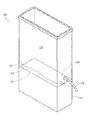
- FIG. 1 illustrates a perspective view of an improved containment assembly
- FIG. 2 illustrates an enlarged perspective view of the FIG. 1 , for example, including a liner assembly having with a tube, a liner, and a cuff with a flange;
- FIG. 3 illustrates an enlarged side view, for example, showing the liner assembly of FIG. 2 ;
- FIG. 4 illustrates an enlarged perspective view of a friction cuff, for example, with a flange
- FIG. 5 illustrates an enlarged side view of another liner assembly having a tube, a liner, and a cuff, for example, without a flange.
- FIG. 6 illustrates an enlarged perspective view of another cuff, for example, without a flange
- FIG. 7 illustrates a perspective view of a containment assembly having an alternative liner assembly
- FIG. 8 illustrates an enlarged perspective view of the liner assembly of FIG. 7 ;
- FIG. 9 illustrates another enlarged perspective view of the liner assembly of FIG. 7 ;
- FIG. 10 illustrates another enlarged perspective view of the liner assembly of FIG. 7 ;
- FIG. 11 illustrates a perspective view of an alternative containment assembly
- FIG. 12 illustrates a side view of an alternative containment assembly
- FIG. 13A illustrates a front view of a system of the present disclosure
- FIG. 13B illustrates a cutaway view of the system of FIG. 13A ;
- FIG. 14A illustrates an exemplary tube blocking member of the present disclosure
- FIG. 14B illustrates an alternative tube blocking member of the present disclosure
- FIG. 15A illustrates a front view a liner assembly, for example, with an integrated closure mechanism in a closed configuration
- FIG. 15B illustrates the liner of assembly of FIG. 15A , for example, in an open configuration
- FIG. 15C illustrates exemplary indicia of the present disclosure
- FIG. 16A illustrates a perspective view of an alternative liner assembly, for example, having an integrated closure mechanism with a slide lock in a closed configuration
- FIG. 16B illustrates a perspective view of the liner assembly of FIG. 16A , for example, in an open configuration
- FIG. 17 illustrates a closer, perspective view of the slide lock of FIGS. 16A and 16B ;
- FIG. 18 illustrates a back view of the slide lock of FIG. 17 ;
- FIG. 19 illustrates a front view of the slide lock of FIG. 17 ;
- FIG. 20A illustrates a vertical section view of a slide lock of FIG. 18 ;
- FIG. 20B illustrates a vertical section view of an alternative slide lock of FIG. 18 ;
- FIG. 20C illustrates a vertical section view of an alternative slide lock of FIG. 18 ;
- FIG. 20D illustrates a vertical section view of an alternative slide lock of FIG. 18 ;
- FIG. 21 illustrates a horizontal section view of a slide lock of FIG. 19 ;
- FIG. 22A illustrates another integrated enclosure mechanism, e.g., using a hook and loop fastener
- FIG. 22B illustrates another integrated closure mechanism, e.g., having a plurality of interlocks
- FIG. 23 illustrates an enlarged side view of an alternative liner assembly
- FIG. 24 illustrates an enlarged side view of a method of providing a permanent or tamper-resistant connection
- FIG. 25 illustrates another enlarged side view of a method of providing a permanent or tamper-resistant connection
- FIG. 26 illustrates another enlarged side view of a method of providing a permanent or tamper-resistant connection
- FIG. 27 illustrates a perspective view of a tool, e.g., having one or more end effectors with a recess;
- FIG. 28 illustrates a perspective view of another tool, e.g., having one or more end effectors with an alternative recess;
- FIG. 29 illustrates a perspective view of another tool, e.g., having one or more end effectors with an extrusion
- FIG. 30 illustrates a perspective view of another tool, e.g., having one or more end effectors with an alternative extrusion
- FIG. 31 illustrates a perspective view of another tool, e.g., having one or more end effectors with an alternative extrusion
- FIG. 32 illustrates a perspective view of an alternative cuff
- FIG. 33 illustrates a perspective view of an alternative cuff
- FIG. 34 illustrates a perspective view of an alternative cuff
- FIG. 35 illustrates a perspective view of an alternative cuff
- FIG. 36 illustrates a perspective view of an alternative cuff
- FIG. 37 illustrates a perspective view of an alternative cuff
- FIG. 38 illustrates a perspective view of an alternative cuff
- FIG. 39 illustrates a perspective view of an alternative cuff
- FIG. 40 illustrates a perspective view of an alternative cuff
- FIG. 41 illustrates a perspective view of an alternative cuff
- FIG. 42 illustrates an enlarged side view, for example, of an exemplary liner assembly positioned on an assembly tool
- FIG. 43 illustrates an enlarged side view, for example, of a liner assembly in an assembled condition
- FIG. 44 illustrates an enlarged side view, for example, of a liner assembly in a disassembled condition.
- the exemplary assembly may include a rigid vessel such as an urn, a liner such as a flexible fitted liner with an integrated closure mechanism configured to selectively provide open and closed configurations, a cuff such as a friction cuff configured to be positionable on an inner wall of the liner, a tube such as a flexible tube positionable on an outer wall of the liner, and a spigot that allows for the flexible tubing to be inserted therethrough.
- the vessel may further include a flow operator that pinches the tube to allow controlled dispensing.
- the assembly may be configured to allow for sanitary dispensing of beverages for human consumption.
- the assembly may be configured such that the beverage may bypass the urn or the spigot for easy cleaning. Instead, the assembly may be configured such that the liquid is handled by the liner, cuff, and tube thereby minimizing or preventing contact between the liquid from the vessel.
- a beverage system may comprise a beverage maker, a vessel, and a liner assembly.
- the liner assembly may be configured to be positioned within at least a portion of the vessel.
- the liner assembly may include a liner having an upper portion and a lower portion, an integrated closure mechanism on the upper portion and configured to selectively provide open and closed configurations, a flexible tube on the lower portion, and a cuff having an interlock surface.
- a method may comprise positioning a liner assembly in a vessel, positioning the liner assembly relative to a beverage maker, passing fluid from the beverage maker into the liner assembly, positioning a blocking member in the tube, sealing the integrated closure mechanism, and removing the liner assembly from the vessel.
- a containment assembly 100 may include a vessel 110 and a liner assembly 120 .
- the vessel 110 may include any liquid or beverage dispenser such as a beverage or tea urn.
- the liner assembly 120 may include a tube 130 , a liner 140 such as a flexible liner, and a cuff 160 such as a rigid cuff with or without a flange.
- the liner 140 may be specially dimensioned and configured to match an internal cavity of the vessel 110 and the liner 140 and vessel 110 may include a tapered bottom portion to facilitate flow of liquid therefrom, as discussed in more detail below.
- the liner assembly 120 may be configured to provide a seal between the liner 140 and the tube 130 , for example, using cuff 160 .
- Cuff 160 may include a unitary or one piece component configured to secure the liner 140 and tube 130 together.
- the liner assembly 120 using the cuff 160 , may utilize an interlock such as a friction interlock.
- the interlock may be formed without heat or by cold or heat forming the components of liner assembly 120 to each other.
- the interlock may provide a permanent or tamper-resistant connection between any portions of liner assembly 120 , for example, being destroyed in response to disassembly as a safety feature.
- the tamper-resistant connection may include a tamper evident connection with an indicator as discussed in further detail below.
- the permanent or tamper-resistant connection may be formed by a mechanical interlock or cold or heat forming at least two or all of the tube 130 , liner 140 , and cuff 160 to each other.
- the liner 140 and the tube 130 may be connected with the interlock so as to pinch the liner 120 between the tube 130 and the cuff 160 , e.g., with the cuff 160 expanding the tube 130 radially outward and while the tube 130 applies a radially inward force from the tube 130 to the liner 120 that translates to the cuff 160 .
- the cuff 160 such as a circular spacer with or without a flange, may be positioned inside the tube 130 thereby outwardly expanding a diameter of an inner surface of the tube 130 .
- the liner 140 may be positioned between the tube 130 and the cuff 160 .
- the cuff 160 may outwardly push the liner 140 against an inside surface of the tube 130 thereby providing a seal such as a liquid tight seal.
- the cuff 160 provides a unitary or one piece component that secures the liner 140 relative to the tube 130 thereby eliminating unnecessary components.
- the interlock may provide a fluid tight structure or seal thereby reducing leakage of liquid along the liner assembly 120 and may provide a permanent or tamper-resistant connection between the cuff 160 , liner 140 , and tube 130 that may not be removed without at least partially destroying at least a portion of the liner 140 , e.g., prohibiting or obstructing reassembly of the components of liner assembly 120 and thus the overall functioning of liner assembly 120 with the liner 140 .
- the liner assembly 120 may include the liner 140 interposed between the tube 130 and the cuff 160 .
- the cuff 160 may include an inner surface having a passage for receipt of liquid from the liner 140 and an outer surface that is dimensioned and configured to be received in and outwardly stretch an inner surface of the tube 130 .
- the cuff 160 may be configured to be positioned with an axial force along the tube 130 and may be configured to expand the tube 130 thereby placing an outward force against the liner 140 and toward the inner surface of tube 130 .
- the tube 130 may place an inward force against the liner 140 and toward the outer surface of the cuff 160 .
- the liner assembly 120 may be cold-formed or heat-formed with the axial force, outward force, inward force, or a combination thereof, thereby creating an interlock between the tube 130 , liner 140 , and cuff 160 .
- the cold-formed or heat-formed connection may include plastically forming the tube 130 , liner 140 , and cuff 160 together so as to form a physically joined or merged connection or may include elastically forming the tube 130 , liner 140 , and 160 together so as to form a forced or press fit connection.
- the liner 140 may be held between the tube 130 and the cuff 160 thereby providing a permanent or tamper-resistant connection between the cuff 160 , liner 140 , and tube 130 that may not be removed without at least partially destroying at least a portion of the liner 140 , e.g., that cannot be reassembled to form a functional liner assembly 120 .
- the liner assembly 120 may be configured for a permanent or tamper-resistant connection between tube 130 , liner 140 , and cuff 160 , for example, being at least partially destroyed in response to disassembly.
- the liner assembly 120 e.g., liner 140 and/or tube 130
- the liner assembly 120 may be configured to at least partially destruct, rip or tear in the event of disassembly thereby providing a permanent or tamper-resistant liner assembly 120 in response to disassembly, e.g., prohibiting or obstructing reassembly and reformation of a functioning liner assembly 120 .
- the tube 130 , liner 140 , and cuff 160 may be connected using an interlock such as an adhesive or heat seal thereby providing a permanent or tamper-resistant liner assembly 120 , for example, being at least partially destroyed in response to disassembly.
- liner assembly 120 may utilize any other destructive interlock between the tube 130 , liner 140 , and cuff 160 that results in at least partial destruction of at least one of the tube 130 , liner 140 , and cuff 160 during disassembly.
- the liner assembly 120 may be configured to provide a permanent or tamper-resistant connection, for example, being at least partially destroyed in response to disassembly.
- the liner assembly 120 may include the cuff 160 with a flange 164 as shown in FIG. 4 or without a flange 164 as shown in FIG. 6 .
- the cuff 160 may include a rigid cuff, for example, configured to resist bending of the flange 164 and maintain a passage therethrough.
- the flange 164 may be configured to maintain the liner 140 in an outward position relative to the tube 130 , for example, to resist blockage of the passage of the cuff 160 .
- the flange 164 may be configured to releasably contact or push against the liner 140 or may be adhered or heat sealed thereto.
- the cuff 160 may be without a flange 164 , for example, to allow relative inward movement of the liner 140 .
- the liner 140 may be affixed (e.g., permanently so as to prohibit reassembly of liner assembly 120 after being pulled apart) relative to the cuff 160 and tube 130 .
- the liner assembly 120 may include an optional adhesive 150 (e.g., a food grade adhesive) thereby permanently adhering the tube 130 , liner 140 , and cuff 160 together.
- the liner 140 may be affixed relative to the cuff 160 and tube 130 using a heat seal thereby permanently fusing the tube 130 , liner 140 , and cuff 160 together. By permanently fusing these components they are not intended to be separated.
- the cuff 160 may include an interlock surface 162 .
- the interlock surface 162 may be configured to provide or facilitate the interlock between the cuff 160 , liner 140 , and tube 130 .
- the interlock surface 162 may include a plurality of barbs, ribs, or protrusions interposed by a plurality of recesses, thereby resulting in an increased surface area and a higher coefficient of friction. For example, this may create a plurality of ridges with alternating valleys as shown in FIG. 4 .
- the interlock surface 162 may include a plurality of pores.
- the interlock surface 162 may be a smooth surface.
- the interlock surface 162 may facilitate the interlock and resulting seal between the cuff 160 , liner 140 , and tube 130 .
- the dimensions of the liner 140 are configured to allow for a minimum amount of liner material to be used for the specific vessel 110 that is being lined. This reduces the number of folds created when the liner is installed into the vessel and filled, thus improving drainage of the liquid product.
- the liner 140 may be constructed from a tube of flexible material having one end sealed closed. The tube 130 is attached to the liner 140 , which may occur proximal to the sealed end of the liner 140 at a point configured to assist in draining the beverage product in its entirety from the liner 140 .
- the liner 140 may be dimensioned and configured to provide an optimum size to reduce material usage and improve draining with respect to the vessel 110 .
- the liner 140 may be optimized or dimensioned according to a vessel length, a vessel height, a vessel opening perimeter or circumference, and a spigot location relative to a length and a width of the vessel 110 .
- the liner 140 may be made from flat tubing, gusseted tubing, sheeting, or a flexible pouch having opposed sidewalls that may be optionally connected at peripheral edges.
- the liner 140 may include a lower portion 145 that may be cut and formed by a heat seal, e.g., thereby forming a bottom.
- the lower portion 145 may include a gusset as shown in FIGS. 1 and 7 or a flat edge as shown in FIG. 13 , described in further detail below.
- the liner 140 may be any shape configured to form-fit to the vessel 110 .
- the liner 140 may be configure to be stretched over the top edge of the vessel 110 , for example, to keep the liner 140 from sliding down inside of the vessel 110 upon being filled.
- Methods of manufacturing the liner 140 are contemplated. Methods may include converting raw material into roll stock and converting the roll stock into individual liners 140 .
- the raw material may be in the form of roll stock, for example, dimensioned according to a vessel length and a vessel width of the vessel 110 .
- the roll stock may then be converted by cutting (e.g., using heat or a cutter) the liner 140 to an optimum liner length (e.g., a vessel height of vessel 110 ) thereby resulting in an end open at the top of the liner 140 and a bottom of the liner 140 that is sealed.
- a method may include positioning the cuff 160 (e.g., a friction cuff) over a locating stud 161 of an assembly tool or platform 163 as shown in FIG. 42 , positioning the liner 140 over at least a portion of the cuff 160 and locating stud, and pushing tubing 130 over at least a portion of the liner 140 , cuff 160 , and the locating stud 161 , thereby outwardly expanding the tube 130 and puncturing the liner 140 .
- puncturing the liner 140 allows fluid to flow from the liner 140 through the cuff 160 , and into the tube 130 .
- the tube 130 , liner 140 , and cuff 160 are held together (e.g., permanently such that the liner assembly 120 prohibits or obstructs reassembly and formation of a functional, working condition after disassembly) by an inward force from the elasticity of the tube 130 and a friction force between the tube 130 , liner 140 , and cuff 160 .
- any or all of tube 130 , liner 140 , and cuff 160 may be held together (e.g., permanently) using an interlock such as an adhesive or a heat seal therebetween.
- the liner assembly 120 may be configured with layers having an order from inside to outside as follows: the cuff 160 (e.g., a friction cuff), the liner 140 , and the tubing 130 (e.g., flexible tube).
- a method may further include removing the liner assembly 120 from the assembly tool or platform and packing the liner assembly 120 for distribution.
- an assembly 200 may include a vessel 110 and a liner assembly 120 .
- the vessel 110 may include a support surface 170 .
- the liner assembly 120 may include a liner 210 (e.g., a fitted flexible liner), a tube 220 (e.g., a flexible tubing), and a heat seal 230 .
- the liner 210 may include a single piece heat sealed liner dimensioned and figured for the vessel 110 .
- the liner 210 may be directly attached to a tube 220 with the heat seal 230 .
- the heat seal 230 may provide a permanent or tamper-resistant connection, for example, being at least partially destroyed in response to disassembly.
- the heat seal 230 may be created by using a tool such as a heat probe.
- the heated probe may push the liner 210 into an inner surface of the tube 220 thereby sealing an outer surface of the liner 210 at the point at which the liner 210 contacts the inner surface and end of the tube 220 .
- Liner 210 and tube 220 may be interchangeable with liner 140 and tube 130 , respectively.
- the liner 210 may be dimensioned and configured to allow for a minimum amount of liner material to be used for the specific vessel 110 being lined. This may reduce the number of folds created when the liner 210 is installed into the vessel 110 and filled, thus improving drainage of the liquid or product.
- the liner 210 may be constructed from a tube 220 of flexible material having one end sealed closed. The tube 220 and liner 210 may be permanently attached, which may occur proximal to the sealed end of the liner 210 at a point configured to assist in draining the product in its entirety from the liner 210 . The liner 210 may then be placed over a locating board with heat probe for sealing.
- the tube 220 may then be placed above the heat probe and a foot operated pedal may then pushes the heat probe through a hole in the locating board thereby forming the heat seal 230 .
- the liner assembly 120 may include the layers from inside to outside as follows: liner 210 , heat seal 230 , and tube 220 .
- an assembly 300 may include the vessel 110 and the liner assembly 120
- the liner 140 , the vessel 110 , or both the liner 140 and vessel 110 may be configured with a tapered structure, for example as a bottom of the liner 140 and/or the support surface 170 of the vessel 110 .
- the tapered structure may optimize utilization of fluid in the liner 140 by urging fluid toward the tube 130 .
- the tapered structure may include any structure configured to urge liquid toward the tube 130 of the liner assembly 120 and/or spigot of the vessel 110 .
- the tapered structure may include any number of tapered surfaces as part of the vessel 110 or liner 140 that are configured to angle or slope liquid toward the spigot of the vessel 110 .
- the tapered structure may include two tapered surfaces forming a v-shape (e.g., along a lengthwise, central axis of the vessel 110 ) as shown in FIG. 11 , may be tapered downwards from a first end (e.g., a backend) to a second end (e.g., a front end) of the vessel 110 as shown in FIG. 12 , or may be a combination thereof.
- the bottom of liner 140 or the support surface 170 of vessel 110 may include the tapered structure.
- the liner 140 may have any number of gussets or may be heat sealed to form a tapered structure as shown in FIGS. 11 and 12 .
- the vessel 110 and liner 140 may be configured to taper fluid out of the liner 140 and toward the tube 130 thereby optimizing usage of the fluid.
- a beverage system 400 may include a beverage maker 402 , vessel 110 , and liner assembly 120 .
- the beverage maker 402 may include a tea or coffee maker.
- the beverage maker 402 may include a fluid source 403 configured to dispense or heat fluid such as water, a filter portion 404 configured to pass the fluid through a flavor source such as tea leaves or coffee beans (e.g., ground), and a base portion 405 configured to provide support for and position the brewing portion 402 and filter portion 404 over the vessel 110 .
- the liner assembly 120 may be received in and folded over the vessel 110 , e.g., to receive fluid in the form of tea or coffee or other beverage.
- the vessel 110 may include a spigot 408 .
- the spigot 408 may have a spigot passage 412 dimensioned to receive tube 130 .
- the spigot 408 may include a flow operator 414 and a pin 415 .
- the flow operator 414 may be moved to provide a plurality of flow rates by selectively opening and closing the tube 103 in open and closed positions and any number of intermediary positions therebetween.
- the flow operator 414 may be operatively connected to a pin 415 to provide an obstruction force to selectively pinch or collapse the tube 130 . By movement in the opposite direction, the flow operator 414 may release the tube 130 , thereby allow fluid to flow for dispensing of the beverage or the tube 130 to pass therethrough for removal of the liner assembly 120 .
- the liner assembly 102 may include, for example, a blocking member 406 .
- the blocking member 406 may be selectively received in the tube 130 to block fluid flow (e.g., to move or store the liner assembly 102 ) and selectively removed from the tube 130 to allow fluid flow (e.g., to dispense a beverage).
- the blocking member 406 may include a head 410 configured to pass though spigot passage 412 and provide a seal relative to the tube 130 .
- the blocking member 406 may further include a shaft 416 and a leading end 418 configured to provide an outward force relative to the tube 130 , thereby securing the blocking member 406 relative to the tube 130 .
- the blocking member 406 may include a leading end 418 with a circumferential extrusion such as a band or ridge about the shaft 416 as shown in FIG. 14A or a pointed extrusion such as a prong as shown in FIG. 14B .
- the liner assembly 120 may be configured to selectively sealed.
- the liner assembly 120 may include an integrated closure mechanism 180 having first and second portions providing an interlock along an upper portion the liner assembly 120 , e.g., a top opening of the liner assembly 120 .
- the integrated closure mechanism 180 may be configured to selectively seal first and second portions of the liner assembly 120 relative to each other, e.g., using interlocking ridges along the integrated closure mechanism 180 to provide a liner seal.
- the integrated closure mechanism 180 may provide a closed configuration to seal the interior of or retain the fluid in the liner assembly 120 .
- FIG. 15A the integrated closure mechanism 180 may provide a closed configuration to seal the interior of or retain the fluid in the liner assembly 120 .
- the integrated closure mechanism 180 may provide a partially or entirely open configuration to provide access to the interior of or to refill fluid into the liner assembly 120 .
- the liner assembly 120 may also include a slide lock 182 that may slide along the integrated closure mechanism 180 between a closed configuration as shown in FIG. 16A and an open configuration as shown in FIG. 16B .
- the liner assembly 120 may include a compartment 151 .
- the compartment 151 may include a woven or mesh material configured to hold a flavor source such as tea leaves or coffee beans (e.g., ground).
- the compartment 151 may be integral to the liner 140 or positioned in or secured relative to the liner 140 .
- Fluid such as water may be provided in the liner assembly 120 , pass through or against the compartment 151 thereby mixing the fluid and the flavor source, and pass out of the liner assembly 120 as a beverage such as tea or coffee.
- the liner assembly 120 may include a label block 146 as further shown in FIG. 13 .
- the label block 146 may extend all or any portion of the length and width of the liner 140 , e.g., between an upper boundary 147 and a lower boundary 148 .
- the label block 146 may include or may be configured to receive indicia 149 . As shown in FIG.
- indicia 149 may include a brand/logo marker 502 , product marker 504 regarding the contents such as a beverage type (e.g., a type of coffee or tea), fill date marker 506 , fill time marker 508 , liner change date marker 510 , liner change time marker 512 , initials marker 514 , and day of the week marker 516 , e.g., associated with preparation of the beverage or installation or manufacturing of the liner assembly 120 .
- the label block 146 may include an opaque surface configured to be marked with indicia 149 , e.g., using a printer or a writing instrument such as a pen, pencil, or marker. Thus, the block label 146 may provide information regarding the liner assembly 120 and the beverage contained therein.
- the liner assembly 120 may include one or more handles 183 , as shown in FIG. 16A .
- the handles 183 may facilitate the opening and closing of the upper portion of the liner assembly 120 .
- the handles 183 may facilitate the removal of the liner assembly 120 from the vessel 110 and the moving and handling of liner assembly 120 .
- Handles 183 may be integrated into liner 140 .
- Handles 183 stamped during manufacturing of liner 140 or affixed afterwards. Handles 183 may be positioned in any orientation with respect to liner 140 .
- the slide lock 182 a unitary or a multi-component body.
- the slide lock 182 may include a closing end 184 and an opening end 186 .
- the closing end 184 may apply an inward force to urge the integrated closure mechanism 180 together when the slide lock 182 is moved in the direction of the closing end 184 .
- the opening end 186 may apply an outward force to separate the integrated closure mechanism 180 when the slide lock 182 is moved in the direction of the opening end 186 .
- the integrated closure mechanism 182 may selectively seal the liner assembly 120 depending on the position of the slide lock 182 .
- the slide lock 182 may include features to facilitate the inward and outward forces.
- the slide lock 182 may include a divider 188 , e.g., to separate and provide the outward force to separate the integrated closure mechanism 180 , and may include lower arms 190 , 192 , e.g., to provide an inward force on the liner 140 and to slide against and facilitate closure of the portions of liner 140 that are adjacent to integrated closure mechanism 180 .
- the divider 188 may include any profile configured to selectively separate the integrated closure mechanism 180 , e.g., a right angle step profile as shown in FIG. 20A , a tapered ramp profile as shown in FIG.
- the slide lock 182 may include sidewalls 194 , 196 , e.g., to provide the inward force to the integrated closure mechanism 180 , and may taper outwards from the closing end 184 to the opening end 186 , e.g., to facilitate the inward force and closure at the closing end 184 and the outward force and separation at the opening end 186 .
- the slide lock 182 may be configured to provide safety or tamper-resistant features.
- the slide lock 182 may include a first loop member and the liner 140 may have a second loop member, adjacent the slide lock 182 when in the closed configuration.
- the first and second loop members may be secured relative to each other in the closed position with a lock or a one-way zip tie through the first and second loop members.
- the lock or zip tie may be cut or otherwise removed to provide the open configuration.
- tamper resistance may be provided by the slide lock 182 .
- the slide lock 182 may include slider and seal arrangements that may include child resistant systems, e.g., a child resistant easy open (CREO) system may be utilized to facilitate multiple uses of the liner assembly 120 throughout the day.
- CREO child resistant easy open
- the integrated closure mechanism 180 may be a hook and loop type fastener. As shown in FIG. 22A , the integrated closure mechanism 180 may include a first portion 179 configured to selectively receive and release a second portion 181 , thereby providing a seal therebetween. As shown in FIG. 22B , the integrated closure mechanism 180 may include a plurality of the same or different types of closure mechanism. For example, the integrated closure mechanism 180 may include a hook and loop fastener with first portion 179 B and second portion 181 B disposed between the interlocking ridges of first portion 179 A and second portion 181 A and the interlocking ridges of first portion 179 C and second portion 81 C. Thus, any combination of integrated closure mechanisms may provide one or more seals.
- the liner assembly 120 may be configured to fail in the event of disassembly.
- the tube 130 may include a protrusion 131 and the cuff 160 may include a recess 161 , thereby forming a mechanical interlock that allows movement in a first longitudinal direction for assembly but obstructs movement in a second longitudinal direction to obstruct or fail in the event of disassembly.
- a cross-section of the cuff 160 , liner 140 , and/or tube 130 may have a plastic strain or failure stress capacity (e.g., in a longitudinal or torsional direction) that is less than a plastic strain or failure stress capacity of the interlock, e.g., a mechanical interlock or a chemical interlock such as an adhesive.
- a plastic strain or failure stress capacity e.g., in a longitudinal or torsional direction
- the interlock e.g., a mechanical interlock or a chemical interlock such as an adhesive.
- the mechanical interlock may also include a smooth surface, a textured surface, a barbed surface, a press fit connection, or fish hook type connection between the mating surfaces between any or all of the cuff 160 , liner 140 , and tube 130 , e.g., such that an outer diameter of the cuff 160 may be positioned into an inner diameter of the tube 130 so as to provide frictional or obstructive binding therebetween.
- the liner assembly 120 may fail, thus providing tamper resistance.
- system 600 may include a permanent or tamper-resistant connection formed by a mechanical interlock or by heat or cold forming, for example, as discussed above.
- FIG. 24 illustrates cuff 160 being moved against and through liner 140 and into tube 130 .
- cuff 160 may urge the liner 140 into and against the tube 130 , thereby holding the liner 140 , cuff 160 , and tube 130 relative to each other, e.g., forming a tamper resistant connection with fluid tight seal that is destroyed upon disassembly.
- FIG. 25 illustrates a tool 605 positioned relative to and configured to be positioned about the tube 130 , liner 140 , and cuff 160 and generate a bonded connection to permanently melt, weld, or join any or all of the tube 130 , liner 140 , and cuff 160 together.
- energy source 606 may include a mandrel shape and may be configured to engage an outer surface of the tube 130 .
- the tool 605 may include a mandrel configured as a clamp with end effectors 606 a and 606 b that may be opposing and configured to be positioned about and apply a force (e.g., radially inward) to the tube 130 , liner 140 , and cuff 160 .
- the tool 605 may include a mandrel with a single end effector 606 (not shown) configured to be positioned against a rigid object or anchor and apply a force (e.g., radially inward) relative to the tube 130 , liner 140 , and cuff 160 .
- a force e.g., radially inward
- the tool 605 may be configured to provide a force (e.g., radially inward) while applying energy such as thermal energy, friction energy, vibratory energy, or a combination thereof, thereby providing a bonded connection including a heat-formed or cold-formed connection as discussed above.
- the tool 605 may be configured to apply thermal or vibratory energy along all or any portion of any of its surfaces.
- the tool 605 may apply energy for a time period (e.g., predefined) and at a temperature and a pressure (e.g., constant) such that at least the contact areas between the tube 130 , liner 140 , and cuff 160 are heated.
- a time period e.g., predefined
- a temperature and a pressure e.g., constant
- the tool 605 may be configured to transfer the heat to bonding regions 608 while minimizing plastic deformation or melting of an inner surface of cuff 160 and an outer surface of the tube 130 .
- the tool 605 may apply energy in the range of about 300-600° F. for a time period in the range of 1-30 seconds, e.g., about 400° F. for about 15 seconds or about 500° F. for about 6 seconds.
- the tool 605 may include any device configured to apply heat, friction, or vibration to thermally melt, weld, or join any or all of the tube 130 , liner 140 , and cuff 160 , e.g., to generate a unitary, integrated, and/or single piece liner assembly 120 as discussed above.
- the tool 605 may include a radiofrequency (RF), ultrasonic energy, hot bar, or impulse device. Alternatively, solvent bonding may be utilized to chemically join any or all of the tube 130 , liner 140 , and cuff 160 .
- RF radiofrequency
- solvent bonding
- any or all of the tube 130 , liner 140 , and cuff 160 may include thermoplastic materials.
- An exemplary tube 130 may include styrene-ethylene butylene-styrene (SEBS) block copolymer, polypropylene (PP), or a combination thereof or any other material with a melt range of about 360-400° F.
- An exemplary liner 140 may include linear low-density polyethylene (LLDPE), low-density polyethylene (LDPE), nylon, or a combination thereof or any other material having a melt range of about 219-400° F.
- An exemplary cuff 160 may include polyolefin elastomer (POE) or any other material having a melt range between any two of about 205, 225, and 250° F., configured for boiling fill at or above about 212° F. followed by ambient cooling, or configured to receive fluid at or above about 185° F.
- POE polyolefin elastomer
- the tool 605 may include one or more end effectors 606 a/b configured to apply thermal or vibratory energy along all or any portion of any of its surfaces.
- Each end effector 606 a/b may include a recess 610 configured to transfer heat, friction, or vibration to thermally melt, weld, or join any or all of the tube 130 , liner 140 , and cuff 160 .
- Recess 610 may include any shape, e.g., a flat or rectangular shape as shown in FIG. 27 or a round shape as shown in FIG. 28 .
- each end effector 606 a/b may include an extrusion 612 that extends inward from the recess 610 may include any shape, e.g., a circumferential band with a triangular profile as shown in FIG. 29 , a circumferential band with a rounded or semi-circular profile as shown in FIG. 30 , or a hemispherical dimple as shown in FIG. 31 .
- the cuff 160 may include a number of different configurations.
- the cuff 160 may include an interlock surface 162 that is smooth as shown in FIGS. 32-36 or that is ribbed, grooved, barbed, or textured features 165 as shown in FIGS. 38-41 .
- Cuff 160 may include a leading end 163 that tapers inward from the interlock surface 162 as shown in FIGS. 32-33 .
- feature 165 a may be circumferentially or axially positioned on leading end 163 and feature 165 b may be circumferentially or axially positioned on interlock surface 162 .
- Cuff 160 may include a barb, e.g., in the form of a conical protrusion from the interlock surface 162 that tapers inward as shown in FIGS. 34-41 .
- Cuff 160 may include a leading end 163 that is smooth as shown in FIGS. 32-37, 38, and 40 or textured as shown in FIGS. 39 and 41 .
- Cuff 160 may include a flange 164 that is extended as shown in FIGS. 34 and 38 , shortened as shown in FIGS. 35 and 39 , or no flange as shown in FIGS. 36 and 40 .
- Cuff 160 may also include a plurality of barbs, e.g., a leading end 163 with a conical protrusion that repeats along the interlock surface 162 as shown in FIGS. 37 and 41 .
- the liner 140 may be positioned between the tube 130 and the leading end 163 of the cuff 160 , thereby elastically or plastically deforming any or all of the tube 130 , liner 140 , and cuff 160 together. Such elastic or plastic deformation may be facilitated by or in addition to heat or cold forming any or all of the tube 130 , liner 140 , and cuff 160 together.
- cuff 160 may include any combination of the above.
- the liner assembly 120 may be assembled without a cuff 160 .
- the tube 130 may be positioned between first and second layers of the liner 130 .
- the liner 130 may be connected to or hermetically sealed to an outer surface of the tube 130 , e.g., using a heat seal as discussed above.
- the tube 130 may be positioned between the first and second layers of the liner 130 .
- the liner assembly 120 may include liner 130 and tube 130 , e.g., without cuff 160 .
- the cuff 160 may be positioned over locating stud 161 of an assembly tool or platform 163 .
- the liner 140 may be positioned over locating stud 163 , cuff 160 , and liner 140 .
- the cuff 160 may include an inner surface having a passage for receipt of liquid from the liner 140 and an outer surface that is dimensioned and configured to be received in and outwardly stretch and expand an inner surface of the tube 130 .
- the cuff 160 may be configured to be positioned with an axial force along the tube 130 and may be configured to expand the tube 130 thereby placing an outward force against the liner 140 and toward the inner surface of tube 130 .
- the tube 130 may place an inward force against the liner 140 and toward the outer surface of the cuff 160 .
- the liner assembly 120 may be cold-formed or heat-formed with the axial force, outward force, inward force, or a combination thereof, thereby creating an interlock between the tube 130 , liner 140 , and cuff 160 .
- the liner 140 may be held between the tube 130 and the cuff 160 thereby providing a permanent or tamper-resistant connection between the cuff 160 , liner 140 , and tube 130 that may not be removed without at least partially destroying at least a portion of the liner 140 , e.g., that cannot be reassembled to form a functional liner assembly 120 .
- liner assembly 120 results in an outer seal between the tube 130 and liner 140 and an inner seal between the liner 140 and cuff 160 . If the seal is tampered with, the consumer can visually inspect the seal to determine the condition of the liner assembly 120 .
- FIGS. 43-44 illustrate disassembly of the liner assembly 120 .
- a disassembly force may be applied to liner 140 relative to the liner 140 and cuff 160 in an assembled condition as shown in FIG. 43 .
- leading end 163 of cuff 160 may apply a radially outward force on the tube 130 , e.g., thereby elastically or plastically deforming the tube 130 , liner 140 , and cuff 160 together with the liner 140 extending between the tube 130 and cuff 160 .
- the tamper-resistant connection may include a tamper evident connection, e.g., that provides a connection or seal with an indicator that is visible or visually indicates disassembly or a tampered condition and prohibits or obstructs reassembly after the seal is broken.
- the tamper evident connection may secure the liner 140 between the tube 130 and cuff 160 such that a disassembly force 141 (e.g., in an axial, diagonal, or radially outward direction) results in a disassembled condition in which a liner body of the liner 140 tearing or otherwise separating from a visual indictor portion of the liner 140 that remains secured between the tube 130 and cuff 160 as shown in FIG.
- the liner assembly visually indicates tampering with the visual indictor portion of liner 140 extending from and interposed between the tube 130 and cuff 160 .
- the tamper resistant connection includes the interlock which creates a seal that is tamper evident and prohibits reassembly after the seal is broken.
- the connection further includes an indicator that shows if the liner assembly has been tampered with, e.g., in response to at least partially damaging at least one of the tube 130 , liner 140 and cuff 160 . If a consumer identifies a tampered condition, then it can dispose of the liner and deploy a new liner into an urn.
Landscapes
- Engineering & Computer Science (AREA)
- Mechanical Engineering (AREA)
- Food Science & Technology (AREA)
- Details Of Rigid Or Semi-Rigid Containers (AREA)
- Packages (AREA)
Abstract
Description
Claims (19)
Priority Applications (1)
| Application Number | Priority Date | Filing Date | Title |
|---|---|---|---|
| US15/290,401 US10051990B2 (en) | 2013-11-05 | 2016-10-11 | Liner for a vessel |
Applications Claiming Priority (5)
| Application Number | Priority Date | Filing Date | Title |
|---|---|---|---|
| US201361900102P | 2013-11-05 | 2013-11-05 | |
| US14/533,658 US10227227B2 (en) | 2013-11-05 | 2014-11-05 | Liner for a vessel |
| US14/836,232 US10561272B2 (en) | 2013-11-05 | 2015-08-26 | Selectively sealable liner for a vessel |
| US201562240388P | 2015-10-12 | 2015-10-12 | |
| US15/290,401 US10051990B2 (en) | 2013-11-05 | 2016-10-11 | Liner for a vessel |
Related Parent Applications (1)
| Application Number | Title | Priority Date | Filing Date |
|---|---|---|---|
| US14/836,232 Continuation-In-Part US10561272B2 (en) | 2013-11-05 | 2015-08-26 | Selectively sealable liner for a vessel |
Publications (2)
| Publication Number | Publication Date |
|---|---|
| US20170029170A1 US20170029170A1 (en) | 2017-02-02 |
| US10051990B2 true US10051990B2 (en) | 2018-08-21 |
Family
ID=57886375
Family Applications (1)
| Application Number | Title | Priority Date | Filing Date |
|---|---|---|---|
| US15/290,401 Active US10051990B2 (en) | 2013-11-05 | 2016-10-11 | Liner for a vessel |
Country Status (1)
| Country | Link |
|---|---|
| US (1) | US10051990B2 (en) |
Families Citing this family (3)
| Publication number | Priority date | Publication date | Assignee | Title |
|---|---|---|---|---|
| US10051990B2 (en) * | 2013-11-05 | 2018-08-21 | Plascon Group | Liner for a vessel |
| US20170364073A1 (en) * | 2016-06-21 | 2017-12-21 | Keith Alan Guy | Modular Robotic System |
| US20180028406A1 (en) * | 2016-08-01 | 2018-02-01 | Jim Patton | Secure Controlled Substance Pill Dispensing Device |
Citations (114)
| Publication number | Priority date | Publication date | Assignee | Title |
|---|---|---|---|---|
| US172929A (en) | 1876-02-01 | Improvement in oil-can nozzles | ||
| US261354A (en) | 1882-07-18 | Stop-cock | ||
| US2377261A (en) | 1944-03-25 | 1945-05-29 | Lannie F Norris | Milk dispenser |
| US2549207A (en) | 1945-06-26 | 1951-04-17 | Kestenbaum Saul | Fluid dispensing container with an outlet, a valved, supporting casing for said container, and a conduit from said outlet to said valve |
| US2601319A (en) | 1950-12-08 | 1952-06-24 | Norris Mfg Company | Liquid dispensing cabinet |
| US2681747A (en) | 1952-01-18 | 1954-06-22 | Norris Dispensers Inc | Bulk milk transporting and dispensing apparatus |
| US2718985A (en) | 1954-08-04 | 1955-09-27 | Monitor Process Corp | Milk dispenser |
| US2815887A (en) | 1956-01-17 | 1957-12-10 | Don E Ford | Container liner |
| US2831610A (en) | 1956-09-13 | 1958-04-22 | Chase Bag Company | Liquid dispensing container |
| US2861718A (en) | 1956-04-06 | 1958-11-25 | Winzen Res Inc | Dispensing container |
| US2905560A (en) | 1957-05-20 | 1959-09-22 | Sydney E Bender | Methods and means for handling milk |
| US3081911A (en) | 1960-09-29 | 1963-03-19 | Scholle Container Corp | Drainage fitting for collapsible container |
| US3087655A (en) | 1961-01-30 | 1963-04-30 | Scholle Container Corp | Paperboard container with flexible liner therein |
| US3089622A (en) | 1959-01-07 | 1963-05-14 | Jr Edward B Westlake | Container for liquids |
| US3094154A (en) | 1960-09-16 | 1963-06-18 | Meterflo Dispensers Inc | Beverage dispensers |
| US3096912A (en) | 1962-01-16 | 1963-07-09 | Ervin J Rivette | Ceramic mud dispenser |
| US3123254A (en) | 1964-03-03 | Liquid dispensing container | ||
| US3137415A (en) | 1962-06-19 | 1964-06-16 | John Wood Company | Liquid carrier with disposable flexible inner liner container |
| US3138293A (en) | 1961-03-15 | 1964-06-23 | Scholle Container Corp | Paperboard dispensing container |
| US3173579A (en) | 1964-03-04 | 1965-03-16 | Corrugated Container Company | Disposable type dispensing container package |
| US3178063A (en) | 1962-07-25 | 1965-04-13 | Jr Herbert F Cox | Liners |
| US3212681A (en) | 1963-10-09 | 1965-10-19 | Gen Films Inc | Container structure |
| US3920163A (en) | 1973-07-11 | 1975-11-18 | Jet Spray Cooler Inc | Beverage dispenser with in-bowl whipper |
| GB1416816A (en) | 1972-01-17 | 1975-12-10 | Scholle Corp | Dispensing containers for liquids |
| US3945534A (en) | 1972-12-20 | 1976-03-23 | Baker & Ady, Inc. | Food preparation and dispensing system |
| US3949744A (en) | 1973-09-04 | 1976-04-13 | Ellis Whiteside Clarke | Apparatus for the administration of liquids |
| US3976277A (en) | 1974-09-23 | 1976-08-24 | Tomlinson Industries, Inc. | Pinch tube valve |
| US4044989A (en) | 1974-09-23 | 1977-08-30 | Basel Donald R | Pinch tube valve |
| US4076147A (en) * | 1976-05-04 | 1978-02-28 | Schmit Justin M | Liquid container having a plastic film pouch and a piercing element to open the plastic film pouch |
| US4334640A (en) | 1977-08-08 | 1982-06-15 | Douwe Egberts Koninklijke Tabaksfabriek-Koffiebranderijen-Theehandel B.V. | Exchangeable concentrate container for beverage dispensing machines |
| US4375864A (en) | 1980-07-21 | 1983-03-08 | Scholle Corporation | Container for holding and dispensing fluid |
| EP0084699A1 (en) | 1982-01-22 | 1983-08-03 | Richard Millington And Company Limited | Beverage dispensing apparatus |
| US4445539A (en) | 1979-07-19 | 1984-05-01 | The Coca-Cola Company | Dip tube and valve with quick-disconnect coupling for a collapsible container |
| US4475670A (en) | 1982-07-09 | 1984-10-09 | Rutter Christopher C | Fluid dispenser |
| US4513885A (en) | 1979-05-04 | 1985-04-30 | Cole-Parmer Instrument Company | Dispenser having a flexible fluid container and a rotor compressible fluid discharge tube |
| US4516692A (en) | 1982-02-17 | 1985-05-14 | Williamette Industries, Inc. | Disposable container assembly for liquids or semi-liquids in bulk |
| US4516691A (en) | 1982-01-25 | 1985-05-14 | Trinity Foundation | Pierce turn tap |
| US4516693A (en) | 1983-09-06 | 1985-05-14 | Gaston Roy T | Sanitary drinking water system |
| US4528161A (en) | 1981-08-31 | 1985-07-09 | American Hospital Supply Corp. | Probe for automated liquid dispenser |
| US4606476A (en) | 1985-06-17 | 1986-08-19 | Pocock Richard L | System for sanitizing beverage dispensing systems |
| US4722458A (en) | 1984-09-28 | 1988-02-02 | Kiff Pty. Ltd. | Dispensing valve |
| US4767478A (en) | 1986-09-16 | 1988-08-30 | Triparte Ltd. | Attaching a plastic tube to a web of plastic |
| US4817811A (en) | 1987-04-09 | 1989-04-04 | Sotralentz S.A. | Outlet device for a fluid container |
| US4898303A (en) | 1988-10-27 | 1990-02-06 | Liqui-Box Corporation | Cup-type drink merchandiser with bag-in-box product supply system |
| US4911399A (en) | 1989-06-06 | 1990-03-27 | Anglo-American, Inc. | Cam valve for regulation of fluid flow through flexible tubing |
| US4919306A (en) | 1986-12-17 | 1990-04-24 | Connelly Containers, Inc. | Container for fluent material including a ring-like holder for a bag |
| US4948014A (en) | 1988-10-26 | 1990-08-14 | Rapak, Inc. | Two piece valved fluid dispenser |
| US5064096A (en) | 1990-08-01 | 1991-11-12 | Shield Pack, Inc. | Tank liner-to-outlet neck seal |
| US5188259A (en) | 1991-02-01 | 1993-02-23 | Petit Jeffrey D | Caulking gun with belt worn cartridge |
| US5249716A (en) | 1993-04-12 | 1993-10-05 | Sullivan Paul O | Caulking nozzle assembly |
| US5272236A (en) | 1991-10-15 | 1993-12-21 | The Dow Chemical Company | Elastic substantially linear olefin polymers |
| US5334180A (en) | 1993-04-01 | 1994-08-02 | Abbott Laboratories | Sterile formed, filled and sealed flexible container |
| US5375741A (en) | 1993-05-12 | 1994-12-27 | Encon, Inc. | Container for bulk material and its method of manufacture |
| US5407099A (en) | 1990-07-07 | 1995-04-18 | Minnesota Mining And Manufacturing Company | Device for withdrawing filling material from bags |
| US5516693A (en) | 1987-03-04 | 1996-05-14 | Board Of Trustees Operating Michigan State University | Hybrid gene incorporating a DNA fragment containing a gene coding for an insecticidal protein, plasmids, transformed cyanobacteria expressing such protein and method for use as a biocontrol agent |
| US5549673A (en) | 1990-04-20 | 1996-08-27 | Smith & Nephew Richards Inc. | Phonosurgery implant instruments and a system and method of implantation |
| US5551602A (en) | 1993-04-09 | 1996-09-03 | Kraft Jacobs Suchard, Ag | Apparatus for storing and dispensing hot and cold beverages |
| EP0777604A1 (en) | 1994-09-13 | 1997-06-11 | Rapak Incorporated | Liquid container valve structures for service-line connectors |
| US5639015A (en) | 1994-06-03 | 1997-06-17 | Petriekis; Paul F. | End opening bulk material box |
| US5647511A (en) | 1984-03-29 | 1997-07-15 | Liqui-Box Corporation | Collapsed bag with evacuation channel form unit |
| US5680959A (en) | 1994-09-19 | 1997-10-28 | 21St Century Containers, Ltd. | Bulk container with removable liner, discharge fitment for the liner, and adapter for connection to discharge port of the container |
| US5732854A (en) | 1994-03-09 | 1998-03-31 | Ruben; Robert M. | Device, method, and system for controlling volume of collapsible squeeze tubes, and methods of making and using the same |
| US5797524A (en) | 1996-09-18 | 1998-08-25 | Rapid Cartridge Dispensing Systems, Inc. | Spigot actuator assembly and method |
| US5884648A (en) | 1997-08-27 | 1999-03-23 | Scholle Corporation | Coupling valve apparatus and method |
| US5983964A (en) | 1995-12-05 | 1999-11-16 | Packaging Systems, L.L.C. | Method and apparatus for coupling with a spout |
| US6053360A (en) | 1998-07-01 | 2000-04-25 | Packaging Systems, Inc. | Fitment for a flexible container |
| US6062413A (en) | 1996-01-23 | 2000-05-16 | Redmond; Sanford | Reclosable dispenser package, reclosable outlet forming structure and method and apparatus for making same |
| US6073807A (en) | 1998-11-18 | 2000-06-13 | Packaging Systems, Inc. | Flexible container with evacuation form insert |
| US6116467A (en) * | 1998-12-04 | 2000-09-12 | Packaging Systems, Inc. | Beverage dispensing system |
| US6131767A (en) | 1998-09-09 | 2000-10-17 | Scholle Corporation | Tap for dispensing fluid |
| US6138878A (en) | 1998-11-16 | 2000-10-31 | Scholle Corporation | Taps and containers for dispensing fluid |
| US6168074B1 (en) | 1994-06-03 | 2001-01-02 | Packaging Systems, Inc. | End opening bulk material box |
| US6200300B1 (en) | 1998-11-18 | 2001-03-13 | David S. Smith Packaging Limited | Hangable container |
| US6202370B1 (en) | 1999-07-02 | 2001-03-20 | Elmer Jefferson Miller | Method and device for a flexible liner for a cementitious vault wall |
| US6378730B1 (en) | 2000-10-27 | 2002-04-30 | Nestec S.A. | Quick-locking device for effecting hygienic transfer of flowable material from a container by piercing |
| US6607097B2 (en) | 1999-11-10 | 2003-08-19 | Scholle Corporation | Collapsible bag for dispensing liquids and method |
| US6609636B1 (en) | 2000-05-30 | 2003-08-26 | Packaging Systems Llc | Flexible container for bag-in-box packaging system |
| US20040099687A1 (en) | 2000-06-09 | 2004-05-27 | Magermans Marcel Peter | Drink dispensing device and container for drink provided with positioning means |
| US20040104246A1 (en) | 2000-12-20 | 2004-06-03 | Susumu Kawaguchi | Adaptor for beverage pack and beverage feeder |
| US6883683B1 (en) | 2003-04-25 | 2005-04-26 | Daniel A. Cunningham | Tamper resistant beverage dispensing bag |
| US20050269354A1 (en) | 2003-03-10 | 2005-12-08 | Smith Mark A | Puncturable spout |
| US20070205216A1 (en) | 2006-03-01 | 2007-09-06 | Smith Mark A | Puncturable cap and piercer |
| US7316329B2 (en) | 2002-05-03 | 2008-01-08 | Advanced Technology Materials, Inc. | Returnable and reusable, bag-in-drum fluid storage and dispensing container system |
| US20080029540A1 (en) | 2006-07-31 | 2008-02-07 | Johnson James W | Piercing fitment assembly |
| US20080245816A1 (en) | 2005-03-15 | 2008-10-09 | Ds Smith Plastics Ltd. | Tap with Foil-Piercing Device for Liquid Containers |
| US7452317B2 (en) | 2005-05-19 | 2008-11-18 | Smurfit-Stone Container Enterprises, Inc. | Air evacuation systems and methods for lining a container |
| WO2009019610A2 (en) | 2007-08-06 | 2009-02-12 | Ds Smith Plastics Limited | Dispensing device |
| US20090084267A1 (en) * | 2007-09-29 | 2009-04-02 | Pendotech | Bubble trap assembly for critical bioprocess applications |
| US20090127285A1 (en) | 2005-12-16 | 2009-05-21 | D.S. Smith Plastics Limited | Dispensing device |
| US7543723B2 (en) | 2004-03-02 | 2009-06-09 | Ds Smith Plastics Limited | Air vented liquid valve |
| US7641170B2 (en) | 2003-10-02 | 2010-01-05 | Anheuser-Busch, Inc. | Pinch faucet |
| US7721755B2 (en) | 2005-01-26 | 2010-05-25 | Ds Smith Plastics Limited | Valve for controlling the flow of fluids |
| US7721921B2 (en) | 2004-05-14 | 2010-05-25 | Koninklijke Philips Electronics N.V. | Tap unit for a beverage dispenser |
| US7721774B2 (en) | 2006-12-18 | 2010-05-25 | Lbp Manufacturing, Inc. | Filling device for use with a container |
| US7757907B2 (en) | 2006-07-07 | 2010-07-20 | Ds Smith Plastics Limited | Spout for ensuring evacuation of a flexible container |
| US20100200613A1 (en) | 2009-02-11 | 2010-08-12 | Ds Smith Plastics Limited | Disposable assembly for a reusable urn or vessel |
| US20100206900A1 (en) | 2007-05-30 | 2010-08-19 | Koninklijke Philips Electronics N.V. | Paper-based beer container and dispensing appratus therefor |
| WO2010100435A1 (en) | 2009-03-05 | 2010-09-10 | Ds Smith Plastics Limited | Connector assembly for supplying fluid |
| US20100296858A1 (en) | 2009-05-20 | 2010-11-25 | David S. Smith America, Inc. (D.B.A. Worldwide Dispensers) | Dispensing pen incorporating a dome spring element |
| US20110046585A1 (en) | 2002-09-03 | 2011-02-24 | Bluesky Medical Group, Inc. | Reduced pressure treatment system |
| US7922212B2 (en) * | 2003-10-17 | 2011-04-12 | Twin Bay Medical, Inc. | Barb clamp with smooth bore |
| US8006874B2 (en) | 2007-03-02 | 2011-08-30 | Ds Smith Plastics Limited | Child resistant closure for a tap |
| US8052012B2 (en) | 2008-05-19 | 2011-11-08 | Millercoors, Llc | Regulated fluid dispensing device and method of dispensing a carbonated beverage |
| US20110309279A1 (en) | 2010-06-21 | 2011-12-22 | David S. Smith America, Inc. DBA Worldwide Dispensers | Flow valve with integral spring and seal |
| US8091864B2 (en) | 2005-12-20 | 2012-01-10 | Ds Smith Plastics Limited | Valve for a fluid flow connector having an overmolded plunger |
| US8113239B2 (en) | 2009-05-07 | 2012-02-14 | David S. Smith America, Inc. | Vented valve assembly |
| WO2012073004A2 (en) | 2010-11-29 | 2012-06-07 | Ian Darby | Container, container blank, and method of manufacture |
| USD676320S1 (en) | 2011-10-25 | 2013-02-19 | David S. Smith America, Inc. | Fluid dispenser |
| US8397958B2 (en) | 2010-08-05 | 2013-03-19 | Ds Smith Plastics Limited | Closure valve assembly for a container |
| US20130098947A1 (en) | 2011-10-25 | 2013-04-25 | David S. Smith America, Inc., Dba, Worldwide Dispensers | Fluid Dispensing Assembly |
| US8459511B2 (en) | 2008-10-24 | 2013-06-11 | Ds Smith Plastics Limited | Valve |
| US8459510B2 (en) | 2010-07-20 | 2013-06-11 | David S. Smith America, Inc. | Dispenser assembly |
| US20170029170A1 (en) * | 2013-11-05 | 2017-02-02 | Plascon Group | Liner for a vessel |
| US20170057736A1 (en) * | 2015-08-28 | 2017-03-02 | Ds Smith Plastics Limited | Liner for beverage and food vessels |
-
2016
- 2016-10-11 US US15/290,401 patent/US10051990B2/en active Active
Patent Citations (127)
| Publication number | Priority date | Publication date | Assignee | Title |
|---|---|---|---|---|
| US3123254A (en) | 1964-03-03 | Liquid dispensing container | ||
| US261354A (en) | 1882-07-18 | Stop-cock | ||
| US172929A (en) | 1876-02-01 | Improvement in oil-can nozzles | ||
| US2377261A (en) | 1944-03-25 | 1945-05-29 | Lannie F Norris | Milk dispenser |
| US2549207A (en) | 1945-06-26 | 1951-04-17 | Kestenbaum Saul | Fluid dispensing container with an outlet, a valved, supporting casing for said container, and a conduit from said outlet to said valve |
| US2601319A (en) | 1950-12-08 | 1952-06-24 | Norris Mfg Company | Liquid dispensing cabinet |
| US2681747A (en) | 1952-01-18 | 1954-06-22 | Norris Dispensers Inc | Bulk milk transporting and dispensing apparatus |
| US2718985A (en) | 1954-08-04 | 1955-09-27 | Monitor Process Corp | Milk dispenser |
| US2815887A (en) | 1956-01-17 | 1957-12-10 | Don E Ford | Container liner |
| US2861718A (en) | 1956-04-06 | 1958-11-25 | Winzen Res Inc | Dispensing container |
| US2831610A (en) | 1956-09-13 | 1958-04-22 | Chase Bag Company | Liquid dispensing container |
| US2905560A (en) | 1957-05-20 | 1959-09-22 | Sydney E Bender | Methods and means for handling milk |
| US3089622A (en) | 1959-01-07 | 1963-05-14 | Jr Edward B Westlake | Container for liquids |
| US3094154A (en) | 1960-09-16 | 1963-06-18 | Meterflo Dispensers Inc | Beverage dispensers |
| US3081911A (en) | 1960-09-29 | 1963-03-19 | Scholle Container Corp | Drainage fitting for collapsible container |
| US3087655A (en) | 1961-01-30 | 1963-04-30 | Scholle Container Corp | Paperboard container with flexible liner therein |
| US3138293A (en) | 1961-03-15 | 1964-06-23 | Scholle Container Corp | Paperboard dispensing container |
| US3096912A (en) | 1962-01-16 | 1963-07-09 | Ervin J Rivette | Ceramic mud dispenser |
| US3137415A (en) | 1962-06-19 | 1964-06-16 | John Wood Company | Liquid carrier with disposable flexible inner liner container |
| US3178063A (en) | 1962-07-25 | 1965-04-13 | Jr Herbert F Cox | Liners |
| US3212681A (en) | 1963-10-09 | 1965-10-19 | Gen Films Inc | Container structure |
| US3173579A (en) | 1964-03-04 | 1965-03-16 | Corrugated Container Company | Disposable type dispensing container package |
| GB1416816A (en) | 1972-01-17 | 1975-12-10 | Scholle Corp | Dispensing containers for liquids |
| US3945534A (en) | 1972-12-20 | 1976-03-23 | Baker & Ady, Inc. | Food preparation and dispensing system |
| US3920163A (en) | 1973-07-11 | 1975-11-18 | Jet Spray Cooler Inc | Beverage dispenser with in-bowl whipper |
| US3949744A (en) | 1973-09-04 | 1976-04-13 | Ellis Whiteside Clarke | Apparatus for the administration of liquids |
| US3976277A (en) | 1974-09-23 | 1976-08-24 | Tomlinson Industries, Inc. | Pinch tube valve |
| US4044989A (en) | 1974-09-23 | 1977-08-30 | Basel Donald R | Pinch tube valve |
| US4076147A (en) * | 1976-05-04 | 1978-02-28 | Schmit Justin M | Liquid container having a plastic film pouch and a piercing element to open the plastic film pouch |
| US4334640A (en) | 1977-08-08 | 1982-06-15 | Douwe Egberts Koninklijke Tabaksfabriek-Koffiebranderijen-Theehandel B.V. | Exchangeable concentrate container for beverage dispensing machines |
| US4513885A (en) | 1979-05-04 | 1985-04-30 | Cole-Parmer Instrument Company | Dispenser having a flexible fluid container and a rotor compressible fluid discharge tube |
| US4445539A (en) | 1979-07-19 | 1984-05-01 | The Coca-Cola Company | Dip tube and valve with quick-disconnect coupling for a collapsible container |
| US4375864A (en) | 1980-07-21 | 1983-03-08 | Scholle Corporation | Container for holding and dispensing fluid |
| US4528161A (en) | 1981-08-31 | 1985-07-09 | American Hospital Supply Corp. | Probe for automated liquid dispenser |
| EP0084699A1 (en) | 1982-01-22 | 1983-08-03 | Richard Millington And Company Limited | Beverage dispensing apparatus |
| US4516691A (en) | 1982-01-25 | 1985-05-14 | Trinity Foundation | Pierce turn tap |
| US4516692A (en) | 1982-02-17 | 1985-05-14 | Williamette Industries, Inc. | Disposable container assembly for liquids or semi-liquids in bulk |
| US4475670A (en) | 1982-07-09 | 1984-10-09 | Rutter Christopher C | Fluid dispenser |
| US4516693A (en) | 1983-09-06 | 1985-05-14 | Gaston Roy T | Sanitary drinking water system |
| US5647511A (en) | 1984-03-29 | 1997-07-15 | Liqui-Box Corporation | Collapsed bag with evacuation channel form unit |
| US4722458A (en) | 1984-09-28 | 1988-02-02 | Kiff Pty. Ltd. | Dispensing valve |
| US4606476A (en) | 1985-06-17 | 1986-08-19 | Pocock Richard L | System for sanitizing beverage dispensing systems |
| US4767478A (en) | 1986-09-16 | 1988-08-30 | Triparte Ltd. | Attaching a plastic tube to a web of plastic |
| US4919306A (en) | 1986-12-17 | 1990-04-24 | Connelly Containers, Inc. | Container for fluent material including a ring-like holder for a bag |
| US5516693A (en) | 1987-03-04 | 1996-05-14 | Board Of Trustees Operating Michigan State University | Hybrid gene incorporating a DNA fragment containing a gene coding for an insecticidal protein, plasmids, transformed cyanobacteria expressing such protein and method for use as a biocontrol agent |
| US4817811A (en) | 1987-04-09 | 1989-04-04 | Sotralentz S.A. | Outlet device for a fluid container |
| US4948014A (en) | 1988-10-26 | 1990-08-14 | Rapak, Inc. | Two piece valved fluid dispenser |
| US4898303A (en) | 1988-10-27 | 1990-02-06 | Liqui-Box Corporation | Cup-type drink merchandiser with bag-in-box product supply system |
| US4911399A (en) | 1989-06-06 | 1990-03-27 | Anglo-American, Inc. | Cam valve for regulation of fluid flow through flexible tubing |
| US5549673A (en) | 1990-04-20 | 1996-08-27 | Smith & Nephew Richards Inc. | Phonosurgery implant instruments and a system and method of implantation |
| US5407099A (en) | 1990-07-07 | 1995-04-18 | Minnesota Mining And Manufacturing Company | Device for withdrawing filling material from bags |
| US5064096A (en) | 1990-08-01 | 1991-11-12 | Shield Pack, Inc. | Tank liner-to-outlet neck seal |
| US5188259A (en) | 1991-02-01 | 1993-02-23 | Petit Jeffrey D | Caulking gun with belt worn cartridge |
| US5272236A (en) | 1991-10-15 | 1993-12-21 | The Dow Chemical Company | Elastic substantially linear olefin polymers |
| US5334180A (en) | 1993-04-01 | 1994-08-02 | Abbott Laboratories | Sterile formed, filled and sealed flexible container |
| US5551602A (en) | 1993-04-09 | 1996-09-03 | Kraft Jacobs Suchard, Ag | Apparatus for storing and dispensing hot and cold beverages |
| US5249716A (en) | 1993-04-12 | 1993-10-05 | Sullivan Paul O | Caulking nozzle assembly |
| US5375741A (en) | 1993-05-12 | 1994-12-27 | Encon, Inc. | Container for bulk material and its method of manufacture |
| US5732854A (en) | 1994-03-09 | 1998-03-31 | Ruben; Robert M. | Device, method, and system for controlling volume of collapsible squeeze tubes, and methods of making and using the same |
| US6168074B1 (en) | 1994-06-03 | 2001-01-02 | Packaging Systems, Inc. | End opening bulk material box |
| US5639015A (en) | 1994-06-03 | 1997-06-17 | Petriekis; Paul F. | End opening bulk material box |
| US5697410A (en) | 1994-09-13 | 1997-12-16 | Packaging Systems, Inc. | Liquid container valve structures for use with service-line connectors |
| EP0777604A1 (en) | 1994-09-13 | 1997-06-11 | Rapak Incorporated | Liquid container valve structures for service-line connectors |
| US5901761A (en) | 1994-09-13 | 1999-05-11 | Packaging Systems, L.L.C. | Liquid container valve structures for use with service-line connectors |
| US5680959A (en) | 1994-09-19 | 1997-10-28 | 21St Century Containers, Ltd. | Bulk container with removable liner, discharge fitment for the liner, and adapter for connection to discharge port of the container |
| US5983964A (en) | 1995-12-05 | 1999-11-16 | Packaging Systems, L.L.C. | Method and apparatus for coupling with a spout |
| US6062413A (en) | 1996-01-23 | 2000-05-16 | Redmond; Sanford | Reclosable dispenser package, reclosable outlet forming structure and method and apparatus for making same |
| US5797524A (en) | 1996-09-18 | 1998-08-25 | Rapid Cartridge Dispensing Systems, Inc. | Spigot actuator assembly and method |
| US5884648A (en) | 1997-08-27 | 1999-03-23 | Scholle Corporation | Coupling valve apparatus and method |
| US6053360A (en) | 1998-07-01 | 2000-04-25 | Packaging Systems, Inc. | Fitment for a flexible container |
| US6131767A (en) | 1998-09-09 | 2000-10-17 | Scholle Corporation | Tap for dispensing fluid |
| US6138878A (en) | 1998-11-16 | 2000-10-31 | Scholle Corporation | Taps and containers for dispensing fluid |
| US6073807A (en) | 1998-11-18 | 2000-06-13 | Packaging Systems, Inc. | Flexible container with evacuation form insert |
| US6200300B1 (en) | 1998-11-18 | 2001-03-13 | David S. Smith Packaging Limited | Hangable container |
| EP1147055A1 (en) | 1998-11-18 | 2001-10-24 | David S. Smith Packaging Limited | Flexible container with evacuation form insert |
| US6116467A (en) * | 1998-12-04 | 2000-09-12 | Packaging Systems, Inc. | Beverage dispensing system |
| US6202370B1 (en) | 1999-07-02 | 2001-03-20 | Elmer Jefferson Miller | Method and device for a flexible liner for a cementitious vault wall |
| US6607097B2 (en) | 1999-11-10 | 2003-08-19 | Scholle Corporation | Collapsible bag for dispensing liquids and method |
| US6609636B1 (en) | 2000-05-30 | 2003-08-26 | Packaging Systems Llc | Flexible container for bag-in-box packaging system |
| US20040099687A1 (en) | 2000-06-09 | 2004-05-27 | Magermans Marcel Peter | Drink dispensing device and container for drink provided with positioning means |
| US6378730B1 (en) | 2000-10-27 | 2002-04-30 | Nestec S.A. | Quick-locking device for effecting hygienic transfer of flowable material from a container by piercing |
| US20040104246A1 (en) | 2000-12-20 | 2004-06-03 | Susumu Kawaguchi | Adaptor for beverage pack and beverage feeder |
| US7316329B2 (en) | 2002-05-03 | 2008-01-08 | Advanced Technology Materials, Inc. | Returnable and reusable, bag-in-drum fluid storage and dispensing container system |
| US20110046585A1 (en) | 2002-09-03 | 2011-02-24 | Bluesky Medical Group, Inc. | Reduced pressure treatment system |
| US20050269354A1 (en) | 2003-03-10 | 2005-12-08 | Smith Mark A | Puncturable spout |
| US6883683B1 (en) | 2003-04-25 | 2005-04-26 | Daniel A. Cunningham | Tamper resistant beverage dispensing bag |
| US7334702B2 (en) | 2003-04-25 | 2008-02-26 | Parish Manufacturing, Inc. | Tamper resistant beverage dispensing bag |
| US7641170B2 (en) | 2003-10-02 | 2010-01-05 | Anheuser-Busch, Inc. | Pinch faucet |
| US7922212B2 (en) * | 2003-10-17 | 2011-04-12 | Twin Bay Medical, Inc. | Barb clamp with smooth bore |
| US7543723B2 (en) | 2004-03-02 | 2009-06-09 | Ds Smith Plastics Limited | Air vented liquid valve |
| US7721921B2 (en) | 2004-05-14 | 2010-05-25 | Koninklijke Philips Electronics N.V. | Tap unit for a beverage dispenser |
| US7721755B2 (en) | 2005-01-26 | 2010-05-25 | Ds Smith Plastics Limited | Valve for controlling the flow of fluids |
| US20080245816A1 (en) | 2005-03-15 | 2008-10-09 | Ds Smith Plastics Ltd. | Tap with Foil-Piercing Device for Liquid Containers |
| US7452317B2 (en) | 2005-05-19 | 2008-11-18 | Smurfit-Stone Container Enterprises, Inc. | Air evacuation systems and methods for lining a container |
| US20090127285A1 (en) | 2005-12-16 | 2009-05-21 | D.S. Smith Plastics Limited | Dispensing device |
| US8091864B2 (en) | 2005-12-20 | 2012-01-10 | Ds Smith Plastics Limited | Valve for a fluid flow connector having an overmolded plunger |
| US20120223095A1 (en) | 2005-12-20 | 2012-09-06 | Ds Smith Plastics Limited | Valve for a fluid flow connector having an overmolded plunger |
| US7607555B2 (en) | 2006-03-01 | 2009-10-27 | Ds Smith Plastics Limited | Puncturable cap and piercer |
| US20070205216A1 (en) | 2006-03-01 | 2007-09-06 | Smith Mark A | Puncturable cap and piercer |
| US8083109B2 (en) | 2006-07-07 | 2011-12-27 | Smith Mark A | Spout for ensuring evacuation of a flexible container |
| US7757907B2 (en) | 2006-07-07 | 2010-07-20 | Ds Smith Plastics Limited | Spout for ensuring evacuation of a flexible container |
| US20080029540A1 (en) | 2006-07-31 | 2008-02-07 | Johnson James W | Piercing fitment assembly |
| US7980424B2 (en) | 2006-07-31 | 2011-07-19 | Liqui-Box Corporation | Piercing fitment assembly |
| WO2008014605A1 (en) | 2006-07-31 | 2008-02-07 | Liqui-Box Canada, Inc. | A piercing fitment assembly |
| US7721774B2 (en) | 2006-12-18 | 2010-05-25 | Lbp Manufacturing, Inc. | Filling device for use with a container |
| US8006874B2 (en) | 2007-03-02 | 2011-08-30 | Ds Smith Plastics Limited | Child resistant closure for a tap |
| US20100206900A1 (en) | 2007-05-30 | 2010-08-19 | Koninklijke Philips Electronics N.V. | Paper-based beer container and dispensing appratus therefor |
| WO2009019610A2 (en) | 2007-08-06 | 2009-02-12 | Ds Smith Plastics Limited | Dispensing device |
| US20090084267A1 (en) * | 2007-09-29 | 2009-04-02 | Pendotech | Bubble trap assembly for critical bioprocess applications |
| US8052012B2 (en) | 2008-05-19 | 2011-11-08 | Millercoors, Llc | Regulated fluid dispensing device and method of dispensing a carbonated beverage |
| US8459511B2 (en) | 2008-10-24 | 2013-06-11 | Ds Smith Plastics Limited | Valve |
| US8757441B2 (en) | 2009-02-11 | 2014-06-24 | Ds Smith Plastics Limited | Disposable assembly for a reusable urn or vessel |
| US20100200613A1 (en) | 2009-02-11 | 2010-08-12 | Ds Smith Plastics Limited | Disposable assembly for a reusable urn or vessel |
| US8752734B2 (en) | 2009-02-11 | 2014-06-17 | Ds Smith Plastics Limited | Disposable assembly for a reusable urn or vessel |
| US20130037568A1 (en) | 2009-02-11 | 2013-02-14 | Ds Smith Plastics Limited | Disposable assembly for a reusable urn or vessel |
| WO2010100435A1 (en) | 2009-03-05 | 2010-09-10 | Ds Smith Plastics Limited | Connector assembly for supplying fluid |
| US8113239B2 (en) | 2009-05-07 | 2012-02-14 | David S. Smith America, Inc. | Vented valve assembly |
| US20100296858A1 (en) | 2009-05-20 | 2010-11-25 | David S. Smith America, Inc. (D.B.A. Worldwide Dispensers) | Dispensing pen incorporating a dome spring element |
| US20110309279A1 (en) | 2010-06-21 | 2011-12-22 | David S. Smith America, Inc. DBA Worldwide Dispensers | Flow valve with integral spring and seal |
| US8459510B2 (en) | 2010-07-20 | 2013-06-11 | David S. Smith America, Inc. | Dispenser assembly |
| US8397958B2 (en) | 2010-08-05 | 2013-03-19 | Ds Smith Plastics Limited | Closure valve assembly for a container |
| US20130126561A1 (en) | 2010-08-05 | 2013-05-23 | Ds Smith Plastics Limited | Closure valve assembly for a container |
| WO2012073004A2 (en) | 2010-11-29 | 2012-06-07 | Ian Darby | Container, container blank, and method of manufacture |
| USD676320S1 (en) | 2011-10-25 | 2013-02-19 | David S. Smith America, Inc. | Fluid dispenser |
| US20130098947A1 (en) | 2011-10-25 | 2013-04-25 | David S. Smith America, Inc., Dba, Worldwide Dispensers | Fluid Dispensing Assembly |
| US20170029170A1 (en) * | 2013-11-05 | 2017-02-02 | Plascon Group | Liner for a vessel |
| US20170057736A1 (en) * | 2015-08-28 | 2017-03-02 | Ds Smith Plastics Limited | Liner for beverage and food vessels |
Non-Patent Citations (4)
| Title |
|---|
| International Search Report PCT/IB2014/065832. |
| U.S. Appl. No. 14/533,658, filed Nov. 5, 2014, Klein, et al. |
| U.S. Appl. No. 14/836,232, filed Aug. 26, 2015, Peterson. |
| U.S. Appl. No. 14/941,378, filed Nov. 13, 2015, Klein, et al. |
Also Published As
| Publication number | Publication date |
|---|---|
| US20170029170A1 (en) | 2017-02-02 |
Similar Documents
| Publication | Publication Date | Title |
|---|---|---|
| US10561272B2 (en) | Selectively sealable liner for a vessel | |
| US10472225B2 (en) | Liner | |
| US10051990B2 (en) | Liner for a vessel | |
| US8459512B2 (en) | Re-sealable spigot for a collapsible beverage container | |
| CA2749308C (en) | Duckbill flip cap fitment for a collapsible container | |
| US8474665B2 (en) | Re-sealable spigot for a collapsible beverage container | |
| US6800088B1 (en) | Multicompartment ice bag for single patient use | |
| BR112019002004B1 (en) | APPLIANCE, SYSTEM AND METHOD FOR PREPARING AN AMOUNT OF BEVERAGE SUITABLE FOR CONSUMPTION | |
| WO2007101348A1 (en) | Additive storage and selective release apparatus | |
| AU3143302A (en) | Pleated-side bag or sack made of flexible, weldable material | |
| BR112019002009B1 (en) | SYSTEM, APPLIANCE, AND METHOD FOR PREPARING AN AMOUNT OF BEVERAGE SUITABLE FOR CONSUMPTION | |
| BR112019001895B1 (en) | SYSTEM AND APPLIANCE FOR PREPARING AN AMOUNT OF BEVERAGE SUITABLE FOR CONSUMPTION | |
| JP5192286B2 (en) | Spout and spout container | |
| US20150197376A1 (en) | Access Structure | |
| US20050105831A1 (en) | Container for retaining liquids and valve for use in the same | |
| EP3177546B1 (en) | Container for fluids | |
| EP2454169A1 (en) | Opening and closing device | |
| JP5635063B2 (en) | Spout and spout container | |
| AU2005202393A1 (en) | Enhanced slider zipper multiwall bag and associated methods |
Legal Events
| Date | Code | Title | Description |
|---|---|---|---|
| AS | Assignment |
Owner name: PLASCON GROUP, MICHIGAN Free format text: ASSIGNMENT OF ASSIGNORS INTEREST;ASSIGNORS:PETERSON, DAVID E.;KLEIN, MATTHEW P.;REEL/FRAME:039986/0193 Effective date: 20161010 |
|
| STCF | Information on status: patent grant |
Free format text: PATENTED CASE |
|
| AS | Assignment |
Owner name: PLASCON PACKAGING, INC., MICHIGAN Free format text: ASSIGNMENT OF ASSIGNORS INTEREST;ASSIGNOR:PETERSON, DAVID E;REEL/FRAME:049919/0760 Effective date: 20190729 |
|
| AS | Assignment |
Owner name: PLASCON PACKAGING, INC., MICHIGAN Free format text: ASSIGNMENT OF ASSIGNORS INTEREST;ASSIGNOR:KLEIN, MATTHEW P;REEL/FRAME:050470/0882 Effective date: 20190830 |
|
| AS | Assignment |
Owner name: JPMORGAN CHASE BANK, N.A., NEW YORK Free format text: SECURITY INTEREST;ASSIGNOR:PLASCON PACKAGING, INC.;REEL/FRAME:050786/0328 Effective date: 20190813 |
|
| MAFP | Maintenance fee payment |
Free format text: PAYMENT OF MAINTENANCE FEE, 4TH YR, SMALL ENTITY (ORIGINAL EVENT CODE: M2551); ENTITY STATUS OF PATENT OWNER: SMALL ENTITY Year of fee payment: 4 |