US10025805B1 - Systems and methods for automated help - Google Patents
Systems and methods for automated help Download PDFInfo
- Publication number
- US10025805B1 US10025805B1 US14/313,676 US201414313676A US10025805B1 US 10025805 B1 US10025805 B1 US 10025805B1 US 201414313676 A US201414313676 A US 201414313676A US 10025805 B1 US10025805 B1 US 10025805B1
- Authority
- US
- United States
- Prior art keywords
- expertise
- user
- functions
- area
- time
- Prior art date
- Legal status (The legal status is an assumption and is not a legal conclusion. Google has not performed a legal analysis and makes no representation as to the accuracy of the status listed.)
- Active, expires
Links
Images


Classifications
-
- G—PHYSICS
- G06—COMPUTING; CALCULATING OR COUNTING
- G06F—ELECTRIC DIGITAL DATA PROCESSING
- G06F16/00—Information retrieval; Database structures therefor; File system structures therefor
- G06F16/30—Information retrieval; Database structures therefor; File system structures therefor of unstructured textual data
- G06F16/33—Querying
- G06F16/332—Query formulation
- G06F16/3329—Natural language query formulation or dialogue systems
-
- G06F17/30312—
-
- G06F17/30598—
Definitions
- the present invention generally relates to the field of computer-aided design (CAD).
- CAD computer-aided design
- the present invention is directed to a method and associated apparatus to enable automated help with use of a CAD design tool.
- CAD Computer-Aided Design
- CAD tools are typically utilized to create, model, and optimize the design an product or article for subsequent manufacture, typically by rendering a 3D surface representation of the designed product.
- CAD tools typically include a user interface for enabling a user to input design requirements, constraints, required performance criteria, testing criteria, and required elements or materials.
- An embodiment of the invention comprises causing a computer system to receive user inputs for utilizing a plurality of functions of a computer program, causing a computer system to record an amount of time during which the user utilizes each of the plurality of functions, causing a computer system to receive an indication from a user that assistance is requested, causing a computer system to compare the respective amounts of time the user utilizes each of the plurality of functions to one another, to identify which of the plurality of functions have been most frequently used, and based on the identified most frequently used ones of said plurality of functions, causing a computer system to identify expertise to provide assistance to the user.
- Another embodiment of the invention comprises a computer readable medium storing machine-executable instructions including a plurality of modules that are executed by a processor of a computer system, the instructions when executed by the processor causing the computer system to execute a method comprising receiving user inputs for utilizing a plurality of functions of a computer program, recording an amount of time during which said user utilizes each of the plurality of functions, receiving an indication from a user that assistance is requested, comparing the respective amounts of time the user utilizes each of said plurality of functions to one another, to identify which of the plurality of functions have been most frequently used, comparing identified most frequently used ones of the plurality of functions to an indication of expertise of a plurality of experts in the most frequently used ones of the plurality of functions, and identifying a selected one of the plurality of experts having a relatively high indication of expertise in the most frequently used ones of the plurality of functions.
- FIG. 1 is a high level flowchart of the method of an embodiment of the invention
- FIG. 2 is a block diagram of program modules of various embodiments of the invention.
- FIG. 3 is a more detailed flowchart of the method in accordance with an embodiment of the invention.
- FIG. 4 is a more detailed flowchart of the steps executed in step 310 of FIG. 3 ;
- FIG. 5 is a more detailed flowchart of the steps executed in step 320 of FIG. 3 ;
- FIG. 6A is a table mapping actions to associated expertise areas that is used in step 410 of FIG. 4 ;
- FIG. 6B is a table illustrating the data stored by design state database 250 resulting from step 425 of FIG. 4 ;
- FIG. 7 is a diagram of a screen display for step 515 of FIG. 5 ;
- FIG. 8 is a table of the expert listings and associated information in accordance with an embodiment of the invention.
- FIG. 9 is a flowchart of the interactions between the user and the expert once an expert has been selected, in accordance with an embodiment of the invention.
- FIG. 10 is a block diagram view of a system that is controlled in accordance with an embodiment of the invention.
- the invention could be embodied in one of several ways. All of the code modules could be written in any computer language, such as Java or C++. Alternatively, the code modules of the invention could be embedded within an existing 3D CAD/CAM program, such as SolidWorks, AutoCAD, zwCAD from ZWCAD Software Co, TurboCAD from IMSI/Design LLC, or others. If the code modules are separately programmed, they can interact with a CAD product through its application program interface (API). Any code modules of the invention that are integrated into an existing CAD product would be written in an applicable programing language for CAD products, such as LISP.
- API application program interface
- a “structure” may be any object or part having a particular geometry.
- a 3D computer “model” may be a virtual representation of a structure and may be created using an appropriate CAD program, such as those set forth above.
- a “designer” or “user” may be the designer of a 3D computer model, a purchaser, an agent of the purchaser, a consumer, a home user, or a customer, among others.
- Examples of a structure include a piece of sheet metal, a solid cube, a cylindrical pipe, an injection molded plastic toy, an article of clothing such as a shirt made of cotton, and an assembly of various parts such as a vehicle, among others.
- a project (or design) may refer to a CAD model of a part or an assembly of CAD models of parts that may be a virtual representation of a particular structure and may be created using one or more appropriate CAD programs.
- FIG. 1 provides a high level flowchart of the operation of a first embodiment of the invention. While an embodiment of the invention will be described in further detail below, this high level description is provided for ease of understanding.
- the program modules of the invention monitor and store information pertaining to a user's recent interaction with a CAD tool. As will be set forth in more detail below, the gathered information includes the length of time the user spends accessing a particular utility within the CAD program.
- a user transmits a request for help.
- the usage information gathered in step 105 is analyzed to determine which expert is best suited to provide help to the user. As will be described in more detail below, that determination includes assessing where the user has spent most of her time, then the next most amount of time, etc. so she can select particular areas for assistance.
- a connection is established between the expert chosen in step 115 and the user.
- FIG. 2 is a block diagram of the program modules of the invention.
- blocks of computer program code, or modules of code.
- modules the reference to separate “modules” is for ease of illustration and discussion.
- the program code instantiating the invention could be organized in any one of a number of well-known manners to provide the functions described. While it is possible that separate code modules could be created to achieve the separate functions described, that is not required. So for example, we make reference below to a “help center module” 240 and to a “help center switchboard module” 260 . While described separately, in practice the actual modules of code instantiating the functions described for those separate modules could be intermingled . . . they do not have to be separate and independent sequences of code.
- CAD program 200 includes conventional CAD functions modules 210 that are typically found in commercial CAD programs, enabling the design of one or more objects.
- the conventional CAD functions 210 produce a CAD model 220 of the object to be designed.
- the CAD model 220 includes conventional information (such as composition, object dimensions, surface bends, welds, and the like).
- the user interacts with and controls the conventional CAD functions modules (hereinafter “CAD program functions” or “CAD functions” 210 ), to in turn manipulate the resultant CAD model 220 , through graphical user interface (GUI) 230 .
- GUI graphical user interface
- a help center module 240 is provided to enable automated help intervention.
- the help center module 240 includes an observer software module 245 that reads and records recent interactions between the user (via GUI) 230 and the conventional CAD program functions 210 .
- the observer software module 245 includes a design state database 250 that records changes and updates to the CAD model 220 .
- the design state database (as well as all the other databases described herein) can be any commercial relational database product, such as DB2 from IBM or Oracle Database 12c, that can store the information and related tables of information described, and can be either directly a part of the CAD program 200 (as shown), or accessed by the program modules of the invention remotely (such as in a cloud service environment).
- DB2 commercial relational database product
- Oracle Database 12c Oracle Database 12c
- the help center module 240 further includes an expert remote control unit module 255 , which in turn includes an expert interface 257 .
- the expert remote control unit module 255 enables experts to remotely access the CAD program 200 , through the expert interface 257 .
- the expert interface 257 is part of the GUI 230 by which the user interacts with CAD program 200 .
- the expert interface is shown in FIG. 2 as being part of the expert remote control unit module 255 because it is accessed by the expert that is selected by the switchboard module 260 .
- the invention further includes a help center “switchboard” module 260 , which utilizes the output of the design state database 250 to select an expert from the expert database 270 who has listed credentials that are similar to the user's requirements for assistance as indicated by the help center module 240 .
- a help center “switchboard” module 260 utilizes the output of the design state database 250 to select an expert from the expert database 270 who has listed credentials that are similar to the user's requirements for assistance as indicated by the help center module 240 .
- an appropriate expert 280 is selected, and a connection is established between the user and expert 280 by any one of a number of known communication technologies (such as, by way of example and not limitation, video chat such as Skype; landline telephone connection; cellphone/smartphone connection; emails; instant messages, and communications over social media portals such as Facebook and Twitter).
- the help center switchboard module 260 further includes an analyzer module 275 , and an optional payment module 277 .
- the analyzer module 275 compares the output of the design state database 250 , as well as (optionally) inputs from the user via GUI 230 and the CAD model itself 220 , to the entries in the expert database 270 , so as to determine which expert 280 - 280 N should be selected to provide support to the user.
- each of the experts 280 - 280 N may have their own version of CAD program 200 for entering information into the CAD model 220 , while interacting with the user (for example, so that the expert can explain her recommended changes to the CAD model 220 ) through the expert interface 257 .
- step 305 the user enters commands to the control the CAD functions 210 , so as to build the CAD model 220 .
- the observer software module 245 receives those inputs, and in step 310 a record of those inputs is created in the design state database 250 .
- step 315 the user indicates that she wants to invoke the help utility, which prompts the help center module 240 to read out the entries of the design state database 250 for the article under design to the analyzer module 275 of the help center switchboard module 260 .
- step 320 the analyzer module 275 compares the outputs of the design state database 250 to corresponding entries in the expert database 270 , to determine which expert best matches up to the likely subjects of the help request from the user.
- step 325 communications are initiated with the applicable expert 280 , by enabling them through their expert CAD program 285 and the expert remote control unit module 255 to (under step 330 ) control the CAD program functions 210 remotely, so as to manipulate the CAD model 220 directly, while also enabling the expert 280 to interact with the user through expert interface 257 .
- the payment module 277 enables payment by the user for the support services of the expert 280 , which can be completed prior to, or after, the provision of support services. Payment can be in the form of an upfront fee, or based on the amount of time the expert spends providing help, some combination of upfront fee and time billing, or some other basis agreed to by the user.
- the payment module 277 is of the conventional type that enables ecommerce payments using credit cards, PayPal, and the like.
- step 340 when the expert 280 completes providing services to the user, the expert terminates the help session, and the invention returns full control over the CAD program functions 210 and the resultant CAD model 220 to the user, such that the process starts again at step 305 .
- the invention enables the user to terminate the help session at any time by so indicating at the GUI 230 .
- FIG. 4 is a more detailed flowchart of the steps taken by the program modules of the invention in carrying out step 310 of FIG. 3 .
- the process starts with step 305 , where the user inputs are received to control the various CAD program functions 210 .
- step 410 the expertise area of the associated action is characterized by the observer software module 245 , and recorded by observer software module 245 into the design state database 250 .
- the various specifications and manufacturing procedures supported by the CAD system such as “Cut Sheet” and “Place Weld”
- this action/expertise categorization table of FIG. 6A is stored in the design state database 250 . Note that it could be stored elsewhere.
- all the steps relating to material selection (such as steps 602 A and 602 B) are categorized as relating to the group “Material” expertise area in column 604 .
- the design state database 210 would include the names of a variety of expertise areas associated with CAD designs; what is shown in FIG. 6A is simply an example. Moreover, while the table shown in FIG. 6A only shows a single expertise area for each action, multiple expertise areas could be indicated, depending on factors such as preceding steps.
- FIG. 6A also shows an assigned weighing factor 606 for each action.
- the weighing factors are added to given greater emphasis in the determinations set forth below for actions that are more likely to be the basis for a help request. So for example, step 602 C “Activate Undo button” is assigned a weighing factor (or modifier) 606 of “2,” on the rationale that any “Undo” action indicates that the user is undoing a previous action, which indicates a likelihood that the user made a mistake and may seek help.
- an “Idle” action is relatively unlikely to result in a user help request, so as shown in row 602 D it is assigned a weighing factor 606 of “0.5.”
- an Idle action could be assigned a “2” if it occurs for less than a minute (because that may indicate the user is confused about the operation of the applicable function of the program) and a “0.5” if it occurs for more than a minute (on the rationale that a longer period indicates disengagement from the program due to some interruption).
- the assignment of particular weighing factors to particular actions is a matter of design choice.
- the modifiers 606 are determined solely by the action 602 , they could also be determined by the expertise area 604 , or by some combination of 602 and 604 .
- the observer software module 245 compares incoming user actions from GUI 230 and the CAD program functions 210 to the database shown in FIG. 6A to assign applicable expertise areas for each user action.
- step 415 as shown in FIG. 6B , the actions 612 and their assigned expertise areas 614 and weighing factors 616 , along with a “time stamp” of when each action was taken 620 , is entered into the design state database 250 .
- step 420 and with further reference to FIG. 6B the total amount of time 622 spent by the user undertaking each action is calculated by the help center module 240 , along with a running total 624 of the total amount of time spent by the user on each action, which factors in the assigned weighing factor 616 .
- step 425 the calculated time spent 622 and running total 624 are written in to the design state database 250 by the help center module 240 .
- FIG. 6B shows the information as recorded in the design state database 250 as a result of step 425 .
- the running total 624 is recorded for each expertise area only for so long as a user request for help is not received, or for a continuous ten minute period, whichever is longer.
- the actions beginning at “Cut Sheet” 620 A and ending with “Help Center” at 620 B were recorded, because they all occurred within ten minutes of the time the user requested help at step 620 B.
- the rationale for recording not more than ten minutes of activity is that it is far more likely for a user to need help for actions undertaken in the immediately previous ten minutes than for longer periods of time.
- the running total calculated running time shown in column 624 includes two other aspects, the multiplier/weighing factors 616 and certain actions for which running time is not assigned. As shown most clearly with action 620 C, the actual time spent was five seconds, yet the calculated running time associated with that action is ten seconds. That is because the help center module 240 multiplies the time spent for each action in 622 by the multiplier (or weighing factor) 616 for that action, and the resultant is included in the calculated running total 624 .
- step 505 when a user requests help as set forth in step 315 of FIG. 3 (and as reflected by the “Help Center” action 620 B in FIG. 6B ), the help center module 240 reads the design state database 250 for data recorded from the last “begin” action (e.g. 620 D of FIG. 6B ), or within ten minutes in running time from the “Help Center” action 620 B, whichever is shorter.
- the last “begin” action e.g. 620 D of FIG. 6B
- the help center module 240 then lists all the different expertise areas applicable to actions applied toward the calculated running time (as previously discussed, some actions can be discounted from the running time calculation), and determines a summation of the portions of the total running time during which the given expertise areas were applicable (which also includes factoring in the weighing factors for particular actions taken in given expertise areas). So, for the example shown in FIG. 6B , based on the recording of running time expired time help center module 240 would determine that the “Welding” expertise area was applicable to actions undertaken for five minutes, thirty nine seconds of running time; the “Bending” expertise area was applicable to actions undertaken for one minute, fifty six seconds of running time; and the “Cutting” expertise area was applicable to actions undertaken for one minute, forty four seconds of running time.
- the help center module 240 presents the resultant data to the user for selection of help topics.
- a schematic view 700 of the GUI 230 screen providing that information to the user is shown in FIG. 7 .
- the user is given the option of selecting the expertise area for which information is sought.
- the areas are listed in order of decreasing running time; as a practical matter they could be listed in any order.
- the calculated portions of total running time applicable to each expertise area is listed for the convenience of the user; as a practical matter that information does not have to be shown.
- the screen 700 also includes the option of designating the expertise areas as “primary” or “secondary;” that information is used to select experts, as will be described in more detail below.
- the screen includes the option of selecting areas of expertise other than those listed.
- the other areas are selectable from a pulldown menu (where the user clicks to see all the options, and then selects from the listed options) that lists all the expertise areas for the applicable CAD tool; as a practical matter any way of showing the information could be used, use of a pulldown menu is not mandatory. So for example the help center module 240 would populate the pulldown for the “Other” option with the expertise areas shown in FIG. 6A . In that embodiment the information could be pre-populated as the expertise areas are originally assigned, rather than waiting for the help center module to calculate the data in step 510 .
- the specifically listed expertise areas would be only the two with the most running time, and all the other expertise areas applicable to the actions undertaken during the applicable time period discussed above would be presented as selections in the pulldown menu.
- the pulldown menu would only be populated when the help center module 240 carries out step 510 .
- the user provides her selection to help center module 240 , and that selection is provided to analyzer module 275 of help center switchboard module 260 .
- the method of the invention queries the CAD model 220 for attributes of the object to be manufactured, and includes that data along with the data discussed above to the analyzer module 275 of the help center switchboard module 260 .
- attributes include the type of material used, the type of weld, and other specific characteristics of the designed object associated with the expertise areas discussed above. As will be described in more detail below, these attributes are compared to “restrictions” listed in the data accompanying particular experts, to help determine if an otherwise-eligible expert would not be suited to provide assistance for the designed object in question.
- the analyzer module 275 of the help center switchboard module 260 carries out a search on the expert database 270 , looking for experts that have expertise in at least the primary expertise area as indicated either by the user (by virtue of the selection in step 515 ) or by the calculations from help center module 240 (by determining the expertise area with the highest total running time), as well as (optionally) looking for such experts that do not have “restrictions” on their expertise that would render them inapplicable due to the attributes of the CAD model 220 as discussed above.
- FIG. 8 presents an example of the listings of experts in the expert database 270 .
- the rows reflect particular data for each expert.
- Column 801 lists whether the expert is immediately available; a “N” entry means the expert is away, or working on another project, or is otherwise unable or unwilling to provide immediate assistance.
- this information is provided on a real-time basis by the experts; it is to be understood that the information could be updated on a daily or some other periodic, or non-periodic, basis.
- the expert could list usual hours of availability.
- the “Y” could also designate whether or not the expert has signed an agreement under which, amongst other things, she is obligated herself to maintain the confidentiality of information exchanged with the user in providing assistance, and to assign any inventions arising from the engagement.
- the Y/N designation does not reflect this information/status, because all the experts have to agree to such terms in order to be listed.
- the user is provided an opportunity to establish appropriate contractual terms with the expert, before proceeding with an exchange of technical information.
- column 804 indicates an “expertise score” for each expert for the bending expertise area; columns 806 and 808 present similar scores for the cutting and welding expertise areas, respectively.
- Column 801 indicates whether the expert has any expertise in the bending expert area; not the correlation between “N” entries in column 802 and the “0” entries in column 802 .
- Column 805 indicates whether the expert has any expertise in the cutting expertise area (correlating to the respective expertise indicators in column 806 ), and column 807 indicates whether the expert has any expertise in the welding expertise area (correlating to the respective expertise indicators in column 808 ).
- some sort of quantitative indication is provided indicating the relative expertise of the listed experts in all of the expertise areas listed in FIG. 6A (only three of such areas are listed in FIG. 8 solely for the purpose of ease of illustration).
- These relative quality indications . . . or rankings . . . can come from a number of sources.
- the rankings are based on feedback from previous requesters of help in the expertise area in question, and for that reason are articulated on a scale of 1-10. But other alternatives can be used.
- the rankings could be based on results from an independent testing agency. Or they could be based on more subjective factors, such as the number of juried publications from the expert, or the number of years of experience. Yet another is a combination of any one or more of the options listed above.
- the rankings could be determined by a combination of objective factors (number of years of experience in the expertise area, and number of pertinent juried publications), and subjective factors (like customer feedback on a 1-10 scale).
- objective factors number of years of experience in the expertise area, and number of pertinent juried publications
- subjective factors like customer feedback on a 1-10 scale.
- a 0-10 scale is used here (where 0 means no expertise, and 10 means extremely high expertise), any other relative scale could be used.
- the database table includes listings of restrictions 810 . So for example while expert Baker has provided expertise in welding (as indicated by his score of 6), he does not work on tungsten inert gas (TIG) welding. So if the CAD model 220 indicates that type of welding is used, Baker will not be chosen even if his expertise score would otherwise indicate that he is suitable. Optionally, other information could be provided in column 810 on what a given expert will (or will not) provide support for.
- TOG tungsten inert gas
- the analyzer module 275 of help center switchboard module 260 determines the best expert to provide help, based on the highest expertise score for the desired expertise area, and availability (and optionally, whether or not the expert would be disqualified because a restriction 810 is applicable for the desired expertise area).
- the analyzer module 275 determines if there is a tie between designated experts. If there is no tie, the highest ranked expert is designated in step 540 . If there is a tie, in step 535 the analyzer module searches the expert database 270 to compare the relative expertise of the tied experts for the next most important expertise area. This second expertise area is either indicated by the user (in step 515 and as shown in and described with reference to FIG.
- step 520 is calculated by the help center module 240 to identify the expertise area with the second highest total time associated with it (as described above). So, in the example shown in FIG. 8 , if the primary expertise area was “Welding,” the result of step 520 would be to select both Ford and Mayhew, since they both have a score of “9” in column 808 . In this step 530 , if the “Cutting” expertise area is the secondary expertise area for which help may be needed, the scores of Ford (5) and Mayhew (8) are compared in column 806 , and in step 540 Mayhew would be selected. In an embodiment of the invention, in the event that two or more experts are still tied, one more selection criterion could then be applied.
- these other selection criteria could be expertise in a third expertise area; or a simple summation of the expertise indicators for the experts; or some other factor not tied to expertise per se, such as physical proximity; or a combination of one or more of the criterion listed above; or others.
- step 545 the designated expert is then identified to the user by a screen view in GUI 230 .
- the presented screen includes the option to enable the user to allow the expert to assume remote control of the CAD program 200 , and in particular the CAD program functions 210 and the resulting CAD model 220 .
- step 550 the user grants the expert remote access capability, the process continues in step 555 to the flowchart of FIG. 9 . If the user does not wish to grant such remote access, but wishes to obtain help from the expert, in step 560 the user contacts the expert (through email, phone, instant message, internet-based video conference, or some other similar communication method) and the expert provides the requested assistance, until in step 565 the user indicates that no further assistance is needed.
- step 905 of FIG. 9 that indication is received by the expert remote control unit module 255 .
- the expert remote control unit module 255 disables the user's control over the CAD system 200 , such that the expert 280 can have unimpeded access; as a practical matter this step is not required.
- step 915 the expert interface 257 in the expert remote control unit module 255 is activated, enabling the user and expert to exchange information (through email, phone, instant message, internet-based video conference, or some other similar communication method).
- step 920 the CAD model 220 is sent, through the expert remote control unit module 255 of help center module 240 and the help center switchboard module 260 , to the expert CAD program 285 where it is loaded so that the expert can have access to, and update, the CAD model at her location.
- sending the CAD model to the expert 280 requires, amongst other things, that the expert CAD program be the same as, or otherwise compatible with, the CAD program 200 (at least in terms of the CAD program functions 210 ).
- the help center module 240 initiates a handshaking protocol to confirm the programs are the same or compatible, in order to ensure that the expert CAD program 285 of the expert 280 can manipulate the CAD model 220 .
- the expert 280 could then be presented with the option of downloading a compatible program to enable communications, or manipulating the CAD program functions 210 through an application program interface (API).
- API application program interface
- the expert submits a CAD model control command on her expert CAD program 285 , which in step 930 is sent by the help center switchboard module 260 to the expert remote control unit module 255 , which provides the command to both the expert interface module 257 (so that the user can observe, and learn from, the commands issued by the expert 280 ) and to the CAD program function 210 to correspondingly change the CAD model 220 .
- the help center module 240 queries the expert interface 257 to determine if the user has indicated that she wishes to terminate remote expert control.
- step 945 the user's control is re-established, and the user continues her use of CAD program 200 , and the help session is terminated at step 950 .
- any one or more of the aspects and embodiments described herein may be conveniently implemented using one or more machines (e.g., one or more computing devices that are utilized as a user computing device for an electronic document, one or more server devices, such as a document server, etc.) programmed according to the teachings of the present specification, as will be apparent to those of ordinary skill in the computer art.
- Appropriate software coding can readily be prepared by skilled programmers based on the teachings of the present disclosure, as will be apparent to those of ordinary skill in the software art.
- Aspects and implementations discussed above employing software and/or software modules may also include appropriate hardware for assisting in the implementation of the machine executable instructions of the software and/or software module.
- Such software may be a computer program product that employs a machine-readable storage medium.
- a machine-readable storage medium may be any medium that is capable of storing and/or encoding a sequence of instructions for execution by a machine (e.g., a computing device) and that causes the machine to perform any one of the methodologies and/or embodiments described herein. Examples of a machine-readable storage medium include, but are not limited to, a magnetic disk, an optical disc (e.g., CD, CD-R, DVD, DVD-R, etc.), a magneto-optical disk, a read-only memory “ROM” device, a random access memory “RAM” device, a magnetic card, an optical card, a solid-state memory device, an EPROM, an EEPROM, and any combinations thereof.
- a machine-readable medium is intended to include a single medium as well as a collection of physically separate media, such as, for example, a collection of compact discs or one or more hard disk drives in combination with a computer memory.
- a machine-readable storage medium does not include transitory forms of signal transmission.
- Such software may also include information (e.g., data) carried as a data signal on a data carrier, such as a carrier wave.
- a data carrier such as a carrier wave.
- machine-executable information may be included as a data-carrying signal embodied in a data carrier in which the signal encodes a sequence of instruction, or portion thereof, for execution by a machine (e.g., a computing device) and any related information (e.g., data structures and data) that causes the machine to perform any one of the methodologies and/or embodiments described herein.
- Examples of a computing device include, but are not limited to, an electronic book reading device, a computer workstation, a terminal computer, a server computer, a handheld device (e.g., a tablet computer, a smartphone, etc.), a web appliance, a network router, a network switch, a network bridge, any machine capable of executing a sequence of instructions that specify an action to be taken by that machine, and any combinations thereof.
- a computing device may include and/or be included in a kiosk.
- FIG. 10 shows a diagrammatic representation of one embodiment of a computing device in the exemplary form of a computer system 1000 within which a set of instructions for causing a control system, such as the system 200 of FIG. 2 , to perform any one or more of the aspects and/or methodologies of the present disclosure may be executed. It is also contemplated that multiple computing devices may be utilized to implement a specially configured set of instructions for causing one or more of the devices to perform any one or more of the aspects and/or methodologies of the present disclosure.
- Computer system 1000 includes a processor 1004 and a memory 1008 that communicate with each other, and with other components, via a bus 1012 .
- Bus 1012 may include any of several types of bus structures including, but not limited to, a memory bus, a memory controller, a peripheral bus, a local bus, and any combinations thereof, using any of a variety of bus architectures.
- Memory 1008 may include various components (e.g., machine readable media) including, but not limited to, a random access memory component, a read only component, and any combinations thereof.
- a basic input/output system 1016 (BIOS), including basic routines that help to transfer information between elements within computer system 1000 , such as during start-up, may be stored in memory 1008 .
- Memory 1008 may also include (e.g., stored on one or more machine-readable media) instructions (e.g., software) 1020 embodying any one or more of the aspects and/or methodologies of the present disclosure.
- memory 1008 may further include any number of program modules including, but not limited to, an operating system, one or more application programs, other program modules, program data, and any combinations thereof.
- Computer system 1000 may also include a storage device 1024 .
- a storage device e.g., storage device 1024
- Examples of a storage device include, but are not limited to, a hard disk drive, a magnetic disk drive, an optical disc drive in combination with an optical medium, a solid-state memory device, and any combinations thereof.
- Storage device 1024 may be connected to bus 1012 by an appropriate interface (not shown).
- Example interfaces include, but are not limited to, SCSI, advanced technology attachment (ATA), serial ATA, universal serial bus (USB), IEEE 1394 (FIREWIRE), and any combinations thereof.
- storage device 1024 (or one or more components thereof) may be removably interfaced with computer system 1000 (e.g., via an external port connector (not shown)).
- storage device 1024 and an associated machine-readable medium 1028 may provide nonvolatile and/or volatile storage of machine-readable instructions, data structures, program modules, and/or other data for computer system 1000 .
- software 1020 may reside, completely or partially, within machine-readable medium 1028 .
- software 1020 may reside, completely or partially, within processor 1004 .
- Computer system 1000 may also include an input device 1032 .
- a user of computer system 1000 may enter commands and/or other information into computer system 1000 via input device 1032 .
- Examples of an input device 1032 include, but are not limited to, an alpha-numeric input device (e.g., a keyboard), a pointing device, a joystick, a gamepad, an audio input device (e.g., a microphone, a voice response system, etc.), a cursor control device (e.g., a mouse), a touchpad, an optical scanner, a video capture device (e.g., a still camera, a video camera), a touchscreen, and any combinations thereof.
- an alpha-numeric input device e.g., a keyboard
- a pointing device e.g., a joystick, a gamepad
- an audio input device e.g., a microphone, a voice response system, etc.
- a cursor control device e.g., a mouse
- Input device 1032 may be interfaced to bus 1012 via any of a variety of interfaces (not shown) including, but not limited to, a serial interface, a parallel interface, a game port, a USB interface, a FIREWIRE interface, a direct interface to bus 1012 , and any combinations thereof.
- Input device 1032 may include a touch screen interface that may be a part of or separate from display 1036 , discussed further below.
- Input device 1032 may be utilized as a user selection device for selecting one or more graphical representations in a graphical interface as described above.
- a user may also input commands and/or other information to computer system 1000 via storage device 1024 (e.g., a removable disk drive, a flash drive, etc.) and/or network interface device 1040 .
- a network interface device such as network interface device 1040 , may be utilized for connecting computer system 1000 to one or more of a variety of networks, such as network 1044 , and one or more remote devices 1048 connected thereto. Examples of a network interface device include, but are not limited to, a network interface card (e.g., a mobile network interface card, a LAN card), a modem, and any combination thereof.
- Examples of a network include, but are not limited to, a wide area network (e.g., the Internet, an enterprise network), a local area network (e.g., a network associated with an office, a building, a campus or other relatively small geographic space), a telephone network, a data network associated with a telephone/voice provider (e.g., a mobile communications provider data and/or voice network), a direct connection between two computing devices, and any combinations thereof.
- a network such as network 1044 , may employ a wired and/or a wireless mode of communication. In general, any network topology may be used.
- Information e.g., data, software 1020 , etc.
- Computer system 1000 may further include a video display adapter 1052 for communicating a displayable image to a display device, such as display device 1036 .
- a display device include, but are not limited to, a liquid crystal display (LCD), a cathode ray tube (CRT), a plasma display, a light emitting diode (LED) display, and any combinations thereof.
- Display adapter 1052 and display device 1036 may be utilized in combination with processor 1004 to provide graphical representations of aspects of the present disclosure.
- computer system 1000 may include one or more other peripheral output devices including, but not limited to, an audio speaker, a printer, and any combinations thereof.
- peripheral output devices may be connected to bus 1012 via a peripheral interface 1056 .
- peripheral interface 1056 Examples of a peripheral interface include, but are not limited to, a serial port, a USB connection, a FIREWIRE connection, a parallel connection, and any combinations thereof.
- the design state database 250 and the expert database 270 can be stored on a storage device associated with the computer of FIG. 10 (such as in storage device 1024 ) or on storage devices that are the same as those of storage device 1024 , except on a remote device 1048 accessed through the network 1044 via the network interface 1040 (such as would be the case when using a cloud-based database solution as mentioned above with reference to FIG. 2 ).
- the user would have local access to the CAD program 200 , and remote access (as described below) to the help center switchboard module 260 .
- the invention can be implemented in a software-as-a-service through a cloud connection, in which case the user would enter user input data via a GUI 230 that is provided on a remote device 1048 , the experts 280 would have access through their own graphical user interface (not shown), and the remaining portions of the CAD program 200 and the help center switchboard module 260 would be resident on the storage device 1024 of a central (cloud) server 1000 .
Abstract
A method for providing assistance to users of computer programs. The computer system receives user inputs for utilizing the various functions of a computer program. The system records an amount of time during which said user utilizes the respective functions, such that when a user signals that assistance is needed, the system determines which of the program's functions have been most frequently used. The system then finds, and connects to the user, persons having expertise in those respective areas.
Description
The present invention generally relates to the field of computer-aided design (CAD). In particular, the present invention is directed to a method and associated apparatus to enable automated help with use of a CAD design tool.
Computer-Aided Design (CAD) programs are typically utilized to create, model, and optimize the design an product or article for subsequent manufacture, typically by rendering a 3D surface representation of the designed product. CAD tools typically include a user interface for enabling a user to input design requirements, constraints, required performance criteria, testing criteria, and required elements or materials.
Systems to provide help to users of software products are known in the industry. One is the menu-driven help system in applications such as Microsoft Word, in which a user reads through a menu of search topics to find applicable information, by either reviewing an index of help topics or by entering key words that search the index and specific help information to find applicable content.
Another utility to provide general assistance is Ask.com. Ask.com includes a utility with a Q&A community, in which specific questions on general topics can be submitted to groups of experts in those general topics. See http://www.ask.com/answers/browse?qsrc=321&qo=channelNavigation&o=0&1=dir, last visited Jun. 12, 2014.
Finally, remote help systems are also known by which computer support technicians can access users' computers remotely in order to provide support. See for example http://www.apextechservices.com/it-consulting/gl10202013.aspx?gclid=COvK27np274CFc9 xOgodeBcAig, last visited Jun. 12, 2014.
Accordingly, while prior art exists for providing remote technical support, that technical support relies on either static menus, or relies on users to articulate their questions in a form understandable to the help system. A need has arisen in the art for help systems that do not rely on static menus or user help request articulation.
An embodiment of the invention comprises causing a computer system to receive user inputs for utilizing a plurality of functions of a computer program, causing a computer system to record an amount of time during which the user utilizes each of the plurality of functions, causing a computer system to receive an indication from a user that assistance is requested, causing a computer system to compare the respective amounts of time the user utilizes each of the plurality of functions to one another, to identify which of the plurality of functions have been most frequently used, and based on the identified most frequently used ones of said plurality of functions, causing a computer system to identify expertise to provide assistance to the user.
Another embodiment of the invention comprises a computer readable medium storing machine-executable instructions including a plurality of modules that are executed by a processor of a computer system, the instructions when executed by the processor causing the computer system to execute a method comprising receiving user inputs for utilizing a plurality of functions of a computer program, recording an amount of time during which said user utilizes each of the plurality of functions, receiving an indication from a user that assistance is requested, comparing the respective amounts of time the user utilizes each of said plurality of functions to one another, to identify which of the plurality of functions have been most frequently used, comparing identified most frequently used ones of the plurality of functions to an indication of expertise of a plurality of experts in the most frequently used ones of the plurality of functions, and identifying a selected one of the plurality of experts having a relatively high indication of expertise in the most frequently used ones of the plurality of functions.
For the purpose of illustrating the invention, the drawings show aspects of one or more embodiments of the invention. However, it should be understood that the present invention is not limited to the precise arrangements and instrumentalities shown in the drawings, wherein:
In the description to follow, flowcharts are used to indicate the methods in accordance with a first embodiment of the invention. These flowcharts indicate corresponding sequences of computer code that accomplish the depicted method steps.
The invention could be embodied in one of several ways. All of the code modules could be written in any computer language, such as Java or C++. Alternatively, the code modules of the invention could be embedded within an existing 3D CAD/CAM program, such as SolidWorks, AutoCAD, zwCAD from ZWCAD Software Co, TurboCAD from IMSI/Design LLC, or others. If the code modules are separately programmed, they can interact with a CAD product through its application program interface (API). Any code modules of the invention that are integrated into an existing CAD product would be written in an applicable programing language for CAD products, such as LISP.
Herein, a “structure” (or the “product” that is designed) may be any object or part having a particular geometry. A 3D computer “model” may be a virtual representation of a structure and may be created using an appropriate CAD program, such as those set forth above. A “designer” or “user” may be the designer of a 3D computer model, a purchaser, an agent of the purchaser, a consumer, a home user, or a customer, among others. Examples of a structure include a piece of sheet metal, a solid cube, a cylindrical pipe, an injection molded plastic toy, an article of clothing such as a shirt made of cotton, and an assembly of various parts such as a vehicle, among others. A project (or design) may refer to a CAD model of a part or an assembly of CAD models of parts that may be a virtual representation of a particular structure and may be created using one or more appropriate CAD programs.
As set forth above, the invention can be designed as either a standalone program that operates a separate CAD program through its APIs, or can be integrated into a conventional CAD program such as those listed above. In the invention CAD program 200 includes conventional CAD functions modules 210 that are typically found in commercial CAD programs, enabling the design of one or more objects. As a result the conventional CAD functions 210 produce a CAD model 220 of the object to be designed. The CAD model 220 includes conventional information (such as composition, object dimensions, surface bends, welds, and the like). The user interacts with and controls the conventional CAD functions modules (hereinafter “CAD program functions” or “CAD functions” 210), to in turn manipulate the resultant CAD model 220, through graphical user interface (GUI) 230.
In the invention, a help center module 240 is provided to enable automated help intervention. As will be described in more detail below, the help center module 240 includes an observer software module 245 that reads and records recent interactions between the user (via GUI) 230 and the conventional CAD program functions 210. As will be described in more detail below, the observer software module 245 includes a design state database 250 that records changes and updates to the CAD model 220. The design state database (as well as all the other databases described herein) can be any commercial relational database product, such as DB2 from IBM or Oracle Database 12c, that can store the information and related tables of information described, and can be either directly a part of the CAD program 200 (as shown), or accessed by the program modules of the invention remotely (such as in a cloud service environment).
The help center module 240 further includes an expert remote control unit module 255, which in turn includes an expert interface 257. The expert remote control unit module 255 enables experts to remotely access the CAD program 200, through the expert interface 257. In a preferred embodiment of the invention the expert interface 257 is part of the GUI 230 by which the user interacts with CAD program 200. The expert interface is shown in FIG. 2 as being part of the expert remote control unit module 255 because it is accessed by the expert that is selected by the switchboard module 260.
The invention further includes a help center “switchboard” module 260, which utilizes the output of the design state database 250 to select an expert from the expert database 270 who has listed credentials that are similar to the user's requirements for assistance as indicated by the help center module 240. As a result, an appropriate expert 280 is selected, and a connection is established between the user and expert 280 by any one of a number of known communication technologies (such as, by way of example and not limitation, video chat such as Skype; landline telephone connection; cellphone/smartphone connection; emails; instant messages, and communications over social media portals such as Facebook and Twitter). The help center switchboard module 260 further includes an analyzer module 275, and an optional payment module 277. As will be described in more detail below, the analyzer module 275 compares the output of the design state database 250, as well as (optionally) inputs from the user via GUI 230 and the CAD model itself 220, to the entries in the expert database 270, so as to determine which expert 280-280N should be selected to provide support to the user. Finally, as described in more detail below, each of the experts 280-280N may have their own version of CAD program 200 for entering information into the CAD model 220, while interacting with the user (for example, so that the expert can explain her recommended changes to the CAD model 220) through the expert interface 257.
With reference to FIG. 3 , a more detailed flowchart of the method of the invention as set forth in FIG. 1 will now be described. The process starts with step 305, in which the user enters commands to the control the CAD functions 210, so as to build the CAD model 220. The observer software module 245 receives those inputs, and in step 310 a record of those inputs is created in the design state database 250. In step 315 the user indicates that she wants to invoke the help utility, which prompts the help center module 240 to read out the entries of the design state database 250 for the article under design to the analyzer module 275 of the help center switchboard module 260.
As previously stated, and as will be described in more detail below with reference to FIG. 5 , in step 320 the analyzer module 275 compares the outputs of the design state database 250 to corresponding entries in the expert database 270, to determine which expert best matches up to the likely subjects of the help request from the user. In step 325 communications are initiated with the applicable expert 280, by enabling them through their expert CAD program 285 and the expert remote control unit module 255 to (under step 330) control the CAD program functions 210 remotely, so as to manipulate the CAD model 220 directly, while also enabling the expert 280 to interact with the user through expert interface 257. Optionally, in step 325, the payment module 277 enables payment by the user for the support services of the expert 280, which can be completed prior to, or after, the provision of support services. Payment can be in the form of an upfront fee, or based on the amount of time the expert spends providing help, some combination of upfront fee and time billing, or some other basis agreed to by the user. The payment module 277 is of the conventional type that enables ecommerce payments using credit cards, PayPal, and the like. Finally, in step 340, when the expert 280 completes providing services to the user, the expert terminates the help session, and the invention returns full control over the CAD program functions 210 and the resultant CAD model 220 to the user, such that the process starts again at step 305. The invention enables the user to terminate the help session at any time by so indicating at the GUI 230.
In step 410 the expertise area of the associated action is characterized by the observer software module 245, and recorded by observer software module 245 into the design state database 250. As shown in FIG. 6A , in the invention the various specifications and manufacturing procedures supported by the CAD system (such as “Cut Sheet” and “Place Weld”) 602 are categorized into functional groups 604 that share a common technology and expertise. For the sake of speed, this action/expertise categorization table of FIG. 6A is stored in the design state database 250. Note that it could be stored elsewhere. By way of example, all the steps relating to material selection (such as steps 602A and 602B) are categorized as relating to the group “Material” expertise area in column 604. As will be apparent to those of skill in the art, the design state database 210 would include the names of a variety of expertise areas associated with CAD designs; what is shown in FIG. 6A is simply an example. Moreover, while the table shown in FIG. 6A only shows a single expertise area for each action, multiple expertise areas could be indicated, depending on factors such as preceding steps.
Therefore, in this step 410, the observer software module 245 compares incoming user actions from GUI 230 and the CAD program functions 210 to the database shown in FIG. 6A to assign applicable expertise areas for each user action. In step 415, as shown in FIG. 6B , the actions 612 and their assigned expertise areas 614 and weighing factors 616, along with a “time stamp” of when each action was taken 620, is entered into the design state database 250. Then, in step 420 and with further reference to FIG. 6B , the total amount of time 622 spent by the user undertaking each action is calculated by the help center module 240, along with a running total 624 of the total amount of time spent by the user on each action, which factors in the assigned weighing factor 616. Finally, in step 425 the calculated time spent 622 and running total 624 are written in to the design state database 250 by the help center module 240.
Note also that the running total calculated running time shown in column 624 includes two other aspects, the multiplier/weighing factors 616 and certain actions for which running time is not assigned. As shown most clearly with action 620C, the actual time spent was five seconds, yet the calculated running time associated with that action is ten seconds. That is because the help center module 240 multiplies the time spent for each action in 622 by the multiplier (or weighing factor) 616 for that action, and the resultant is included in the calculated running total 624. Note that while an embodiment of the invention adds weighing factors to the running total calculation, and discounts one or more steps from the running totals, it is to be understood that the invention can be practiced without applying one or both of those aspects, and for example the invention could calculate running time solely as a function of the time spent on each action, or by only adding the weighing factors, or by only discounting certain steps.
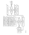
With reference to FIG. 5 , a more detailed description will now be provided of step 320 of FIG. 3 . In step 505, when a user requests help as set forth in step 315 of FIG. 3 (and as reflected by the “Help Center” action 620B in FIG. 6B ), the help center module 240 reads the design state database 250 for data recorded from the last “begin” action (e.g. 620D of FIG. 6B ), or within ten minutes in running time from the “Help Center” action 620B, whichever is shorter. The help center module 240 then lists all the different expertise areas applicable to actions applied toward the calculated running time (as previously discussed, some actions can be discounted from the running time calculation), and determines a summation of the portions of the total running time during which the given expertise areas were applicable (which also includes factoring in the weighing factors for particular actions taken in given expertise areas). So, for the example shown in FIG. 6B , based on the recording of running time expired time help center module 240 would determine that the “Welding” expertise area was applicable to actions undertaken for five minutes, thirty nine seconds of running time; the “Bending” expertise area was applicable to actions undertaken for one minute, fifty six seconds of running time; and the “Cutting” expertise area was applicable to actions undertaken for one minute, forty four seconds of running time.
In step 510, the help center module 240 presents the resultant data to the user for selection of help topics. A schematic view 700 of the GUI 230 screen providing that information to the user is shown in FIG. 7 . The user is given the option of selecting the expertise area for which information is sought. Here, the areas are listed in order of decreasing running time; as a practical matter they could be listed in any order. The calculated portions of total running time applicable to each expertise area is listed for the convenience of the user; as a practical matter that information does not have to be shown. The screen 700 also includes the option of designating the expertise areas as “primary” or “secondary;” that information is used to select experts, as will be described in more detail below. Finally, the screen includes the option of selecting areas of expertise other than those listed. In an embodiment of the invention the other areas are selectable from a pulldown menu (where the user clicks to see all the options, and then selects from the listed options) that lists all the expertise areas for the applicable CAD tool; as a practical matter any way of showing the information could be used, use of a pulldown menu is not mandatory. So for example the help center module 240 would populate the pulldown for the “Other” option with the expertise areas shown in FIG. 6A . In that embodiment the information could be pre-populated as the expertise areas are originally assigned, rather than waiting for the help center module to calculate the data in step 510. In an alternate embodiment of the invention the specifically listed expertise areas would be only the two with the most running time, and all the other expertise areas applicable to the actions undertaken during the applicable time period discussed above would be presented as selections in the pulldown menu. In this embodiment the pulldown menu would only be populated when the help center module 240 carries out step 510. As a result, in step 515 the user provides her selection to help center module 240, and that selection is provided to analyzer module 275 of help center switchboard module 260. Finally, it should be understood that while in this embodiment of the invention the user is presented with an option to select the help topic, the invention could also be practiced without presenting this option to the user; the process could skip steps 505 and 515, and simply provide the resultant of step 505 to analyzer module 275 of help center switchboard module 260.
Continuing with a description of the method of FIG. 5 , prior to initiating the analysis to determine the best expert to contact, as an optional step 520 the method of the invention queries the CAD model 220 for attributes of the object to be manufactured, and includes that data along with the data discussed above to the analyzer module 275 of the help center switchboard module 260. These attributes include the type of material used, the type of weld, and other specific characteristics of the designed object associated with the expertise areas discussed above. As will be described in more detail below, these attributes are compared to “restrictions” listed in the data accompanying particular experts, to help determine if an otherwise-eligible expert would not be suited to provide assistance for the designed object in question. While this optional step has been described with reference to applying the attribute information against a list of “restrictions” of the experts, it is to be understood that it could also be applied to a list of “high expertise” technologies that would make a given expert an even better choice to provide help support.
In step 525, the analyzer module 275 of the help center switchboard module 260 carries out a search on the expert database 270, looking for experts that have expertise in at least the primary expertise area as indicated either by the user (by virtue of the selection in step 515) or by the calculations from help center module 240 (by determining the expertise area with the highest total running time), as well as (optionally) looking for such experts that do not have “restrictions” on their expertise that would render them inapplicable due to the attributes of the CAD model 220 as discussed above.
In FIG. 8 , column 804 indicates an “expertise score” for each expert for the bending expertise area; columns 806 and 808 present similar scores for the cutting and welding expertise areas, respectively. Column 801 indicates whether the expert has any expertise in the bending expert area; not the correlation between “N” entries in column 802 and the “0” entries in column 802. Column 805 indicates whether the expert has any expertise in the cutting expertise area (correlating to the respective expertise indicators in column 806), and column 807 indicates whether the expert has any expertise in the welding expertise area (correlating to the respective expertise indicators in column 808). Note that while all of the “N” entries in columns 802, 805, 807 correlate to “0” entries in columns 804, 806, 808, respectively, as a practical matter an “N” entry could be used to designate low expertise for an expertise score other than “0”, such as for example less than 20.
In the invention, some sort of quantitative indication is provided indicating the relative expertise of the listed experts in all of the expertise areas listed in FIG. 6A (only three of such areas are listed in FIG. 8 solely for the purpose of ease of illustration). These relative quality indications . . . or rankings . . . can come from a number of sources. Preferably, the rankings are based on feedback from previous requesters of help in the expertise area in question, and for that reason are articulated on a scale of 1-10. But other alternatives can be used. The rankings could be based on results from an independent testing agency. Or they could be based on more subjective factors, such as the number of juried publications from the expert, or the number of years of experience. Yet another is a combination of any one or more of the options listed above. For example, the rankings could be determined by a combination of objective factors (number of years of experience in the expertise area, and number of pertinent juried publications), and subjective factors (like customer feedback on a 1-10 scale). Moreover, while a 0-10 scale is used here (where 0 means no expertise, and 10 means extremely high expertise), any other relative scale could be used.
Finally, the database table includes listings of restrictions 810. So for example while expert Baker has provided expertise in welding (as indicated by his score of 6), he does not work on tungsten inert gas (TIG) welding. So if the CAD model 220 indicates that type of welding is used, Baker will not be chosen even if his expertise score would otherwise indicate that he is suitable. Optionally, other information could be provided in column 810 on what a given expert will (or will not) provide support for.
Then, as a result of step 520, the analyzer module 275 of help center switchboard module 260 determines the best expert to provide help, based on the highest expertise score for the desired expertise area, and availability (and optionally, whether or not the expert would be disqualified because a restriction 810 is applicable for the desired expertise area). In step 530, the analyzer module 275 determines if there is a tie between designated experts. If there is no tie, the highest ranked expert is designated in step 540. If there is a tie, in step 535 the analyzer module searches the expert database 270 to compare the relative expertise of the tied experts for the next most important expertise area. This second expertise area is either indicated by the user (in step 515 and as shown in and described with reference to FIG. 7 ), or is calculated by the help center module 240 to identify the expertise area with the second highest total time associated with it (as described above). So, in the example shown in FIG. 8 , if the primary expertise area was “Welding,” the result of step 520 would be to select both Ford and Mayhew, since they both have a score of “9” in column 808. In this step 530, if the “Cutting” expertise area is the secondary expertise area for which help may be needed, the scores of Ford (5) and Mayhew (8) are compared in column 806, and in step 540 Mayhew would be selected. In an embodiment of the invention, in the event that two or more experts are still tied, one more selection criterion could then be applied. By way of example, these other selection criteria could be expertise in a third expertise area; or a simple summation of the expertise indicators for the experts; or some other factor not tied to expertise per se, such as physical proximity; or a combination of one or more of the criterion listed above; or others.
In step 545 the designated expert is then identified to the user by a screen view in GUI 230. The presented screen includes the option to enable the user to allow the expert to assume remote control of the CAD program 200, and in particular the CAD program functions 210 and the resulting CAD model 220. If in step 550 the user grants the expert remote access capability, the process continues in step 555 to the flowchart of FIG. 9 . If the user does not wish to grant such remote access, but wishes to obtain help from the expert, in step 560 the user contacts the expert (through email, phone, instant message, internet-based video conference, or some other similar communication method) and the expert provides the requested assistance, until in step 565 the user indicates that no further assistance is needed.
With reference to FIG. 9 , when in step 550 of FIG. 8 the user indicates that she wants to grant the expert 280 remote access to the CAD system 200, in step 905 of FIG. 9 that indication is received by the expert remote control unit module 255. Optionally, in step 910 the expert remote control unit module 255 disables the user's control over the CAD system 200, such that the expert 280 can have unimpeded access; as a practical matter this step is not required. In step 915 the expert interface 257 in the expert remote control unit module 255 is activated, enabling the user and expert to exchange information (through email, phone, instant message, internet-based video conference, or some other similar communication method). In step 920 the CAD model 220 is sent, through the expert remote control unit module 255 of help center module 240 and the help center switchboard module 260, to the expert CAD program 285 where it is loaded so that the expert can have access to, and update, the CAD model at her location. Note that “sending” the CAD model to the expert 280 requires, amongst other things, that the expert CAD program be the same as, or otherwise compatible with, the CAD program 200 (at least in terms of the CAD program functions 210). As an alternative, in step 920 the help center module 240 initiates a handshaking protocol to confirm the programs are the same or compatible, in order to ensure that the expert CAD program 285 of the expert 280 can manipulate the CAD model 220. The expert 280 could then be presented with the option of downloading a compatible program to enable communications, or manipulating the CAD program functions 210 through an application program interface (API). In step 925 the expert submits a CAD model control command on her expert CAD program 285, which in step 930 is sent by the help center switchboard module 260 to the expert remote control unit module 255, which provides the command to both the expert interface module 257 (so that the user can observe, and learn from, the commands issued by the expert 280) and to the CAD program function 210 to correspondingly change the CAD model 220. In step 940, the help center module 240 queries the expert interface 257 to determine if the user has indicated that she wishes to terminate remote expert control. If so, the expert's remote access is terminated. If not, the process continues with the expert entering another command in step 925. If the user has terminated remote expert control, and if optional step 910 was applied to disable user control of the CAD system, in step 945 the user's control is re-established, and the user continues her use of CAD program 200, and the help session is terminated at step 950.
It is to be noted that any one or more of the aspects and embodiments described herein may be conveniently implemented using one or more machines (e.g., one or more computing devices that are utilized as a user computing device for an electronic document, one or more server devices, such as a document server, etc.) programmed according to the teachings of the present specification, as will be apparent to those of ordinary skill in the computer art. Appropriate software coding can readily be prepared by skilled programmers based on the teachings of the present disclosure, as will be apparent to those of ordinary skill in the software art. Aspects and implementations discussed above employing software and/or software modules may also include appropriate hardware for assisting in the implementation of the machine executable instructions of the software and/or software module.
Such software may be a computer program product that employs a machine-readable storage medium. A machine-readable storage medium may be any medium that is capable of storing and/or encoding a sequence of instructions for execution by a machine (e.g., a computing device) and that causes the machine to perform any one of the methodologies and/or embodiments described herein. Examples of a machine-readable storage medium include, but are not limited to, a magnetic disk, an optical disc (e.g., CD, CD-R, DVD, DVD-R, etc.), a magneto-optical disk, a read-only memory “ROM” device, a random access memory “RAM” device, a magnetic card, an optical card, a solid-state memory device, an EPROM, an EEPROM, and any combinations thereof. A machine-readable medium, as used herein, is intended to include a single medium as well as a collection of physically separate media, such as, for example, a collection of compact discs or one or more hard disk drives in combination with a computer memory. As used herein, a machine-readable storage medium does not include transitory forms of signal transmission.
Such software may also include information (e.g., data) carried as a data signal on a data carrier, such as a carrier wave. For example, machine-executable information may be included as a data-carrying signal embodied in a data carrier in which the signal encodes a sequence of instruction, or portion thereof, for execution by a machine (e.g., a computing device) and any related information (e.g., data structures and data) that causes the machine to perform any one of the methodologies and/or embodiments described herein.
Examples of a computing device include, but are not limited to, an electronic book reading device, a computer workstation, a terminal computer, a server computer, a handheld device (e.g., a tablet computer, a smartphone, etc.), a web appliance, a network router, a network switch, a network bridge, any machine capable of executing a sequence of instructions that specify an action to be taken by that machine, and any combinations thereof. In one example, a computing device may include and/or be included in a kiosk.
A user may also input commands and/or other information to computer system 1000 via storage device 1024 (e.g., a removable disk drive, a flash drive, etc.) and/or network interface device 1040. A network interface device, such as network interface device 1040, may be utilized for connecting computer system 1000 to one or more of a variety of networks, such as network 1044, and one or more remote devices 1048 connected thereto. Examples of a network interface device include, but are not limited to, a network interface card (e.g., a mobile network interface card, a LAN card), a modem, and any combination thereof. Examples of a network include, but are not limited to, a wide area network (e.g., the Internet, an enterprise network), a local area network (e.g., a network associated with an office, a building, a campus or other relatively small geographic space), a telephone network, a data network associated with a telephone/voice provider (e.g., a mobile communications provider data and/or voice network), a direct connection between two computing devices, and any combinations thereof. A network, such as network 1044, may employ a wired and/or a wireless mode of communication. In general, any network topology may be used. Information (e.g., data, software 1020, etc.) may be communicated to and/or from computer system 1000 via network interface device 1040.
In operation, the design state database 250 and the expert database 270 can be stored on a storage device associated with the computer of FIG. 10 (such as in storage device 1024) or on storage devices that are the same as those of storage device 1024, except on a remote device 1048 accessed through the network 1044 via the network interface 1040 (such as would be the case when using a cloud-based database solution as mentioned above with reference to FIG. 2 ). In an embodiment of the invention, the user would have local access to the CAD program 200, and remote access (as described below) to the help center switchboard module 260. Alternatively, the invention can be implemented in a software-as-a-service through a cloud connection, in which case the user would enter user input data via a GUI 230 that is provided on a remote device 1048, the experts 280 would have access through their own graphical user interface (not shown), and the remaining portions of the CAD program 200 and the help center switchboard module 260 would be resident on the storage device 1024 of a central (cloud) server 1000.
The foregoing has been a detailed description of illustrative embodiments of the invention. Various modifications and additions can be made without departing from the spirit and scope of this invention. For example, in addition to the supplier information database 205 as described herein, other supplier-related information that in turn originates from their suppliers (such as logistics/carriers) could be included. In addition, while the invention has been described with reference to a CAD system, the principles of the invention could be applied to other contexts in which help can be provided by subject matter experts. Features of each of the various embodiments described above may be combined with features of other described embodiments as appropriate in order to provide a multiplicity of feature combinations in associated new embodiments. Furthermore, while the foregoing describes a number of separate embodiments, what has been described herein is merely illustrative of the application of the principles of the present invention. Additionally, although particular methods herein may be illustrated and/or described as being performed in a specific order, the ordering is highly variable within ordinary skill to achieve methods, systems, and software according to the present disclosure. Accordingly, this description is meant to be taken only by way of example, and not to otherwise limit the scope of this invention.
Claims (15)
1. On a computer system including at least one processor and at least one computer readable medium storing machine-executable instructions including a plurality of modules that are executed by the processor, a method comprising:
causing the computer system including the at least one processor and the at least one computer readable medium storing machine-executable instructions to receive user inputs for utilizing a plurality of functions of a computer program;
causing the computer system to record an amount of time during which the user utilizes each of the plurality of functions, wherein recording the amount of time further comprises:
detecting a plurality of user actions;
identifying, for each action of the plurality of user actions an area of expertise associated with the action, a time of initiation of the action, and a time spent by the user on the action;
calculating a running total of time spent by the user on all actions over a continuous period using the time spent on by the user on each action of the plurality of user actions; and
writing the time spent on each action and the running total to a design state database;
causing the computer system to receive an indication from a user that assistance is requested;
causing the computer system to identify an area of expertise associated with a greatest usage of functions of the plurality of functions during the period, wherein identifying further comprises:
listing a plurality of areas of expertise, the plurality of areas of expertise including each area of expertise associated with user actions of the plurality of user actions;
summing a total running time per area of expertise by aggregating the time spent by the user on each action of each area of expertise;
determining a proportion of the running total representing the total running time of each area of expertise; and
identifying the area of expertise associated with the largest proportion of the running total; and
based on the identified area of expertise associated with the greatest use of the plurality of functions, causing the computer system to identify expertise to provide assistance to the user.
2. A method according to claim 1 , wherein the step of causing the computer system to record an amount of time during which the user utilizes each of the plurality of functions comprises grouping the functions into a plurality of functional groups, and recording an amount of time during which the user utilizes at least some of the plurality of functional groups.
3. A method according to claim 1 wherein the step of causing the computer system to identify expertise to provide assistance to the user comprises designating one of a plurality of experts.
4. A method according to claim 3 , wherein designating one of the plurality of experts comprises comparing a representation of expertise of each of the plurality of experts for each of the plurality of areas of expertise to the identified area of expertise associated with the greatest usage of functions of the plurality of functions.
5. A non-transitory computer readable medium storing machine-executable instructions including a plurality of modules that are executed by a processor of a computer system, the instructions when executed by the processor causing the computer system to execute a method comprising:
receiving user inputs for utilizing a plurality of functions of a computer program;
recording an amount of time during which the user utilizes each of the plurality of functions, wherein recording the amount of time further comprises:
detecting a plurality of user actions;
identifying, for each action of the plurality of user actions an area of expertise associated with the action, a time of initiation of the action, and a time spent by the user on the action;
calculating a running total of time spent by the user on all actions over a continuous period; and
writing the time spent on each action and the running total to a design state database;
receiving an indication from a user that assistance is requested; identifying an area of expertise associated with a greatest usage of functions of the plurality of functions, wherein identifying further comprises:
listing a plurality of areas of expertise, the plurality of areas of expertise including each area of expertise associated with user actions of the plurality of user actions;
summing a total running time per area of expertise by aggregating the time spent by the user on each action of each area of expertise;
determining a proportion of the running total representing the total running time of each area of expertise;
comparing the identified area of expertise associated with the greatest usage of functions of the plurality of functions to an indication of expertise of a plurality of experts in the area of expertise associated with the greatest usage of functions of the plurality of functions; and
identifying a selected one of the plurality of experts having a relatively high indication of expertise in the area of expertise associated with the greatest usage of functions of the plurality of functions.
6. A method according to claim 5 , wherein the step of recording an amount of time during which the user utilizes each of the plurality of functions comprises grouping the functions into a plurality of functional groups, and recording an amount of time during which the user utilizes each of the plurality of functional groups.
7. A method according to claim 1 , wherein the step identifying a selected one of the plurality of experts further comprises:
assigning an expertise score to at least some of the plurality of experts for at least some of the plurality of areas of expertise;
indicating expert availability; and
selecting experts based on a sort of the plurality of areas of expertise in order of most frequently used, the indication of expert availability, and the expertise score.
8. A method according to claim 7 , further comprising:
indicating activities that a given expert should not be selected to perform, wherein the step of selecting experts is further based on the indication of activities that a given expert should not be selected to perform.
9. A method according to claim 7 , wherein if multiple experts are initially selected based on which of the plurality of areas of expertise is most frequently used, a single expert is selected based on expertise scores of the multiple experts for a next most frequently used of the plurality of areas of expertise.
10. A method according to claim 5 , further comprising:
enabling the selected one of the plurality of experts to control the computer program for which the user requests assistance.
11. A method according to claim 5 , wherein the step of comparing the respective amounts of time the user utilizes each of the plurality of functions to one another further comprises:
assigning a weighing factor to at least some of the plurality of functions; and
adjusting the amount of time the user utilizes a given one of the plurality of functions for which a weighing factor has been assigned, as a function of the weighing factor.
12. A method according to claim 5 , wherein the step of comparing the respective amounts of time the user utilizes each of the plurality of functions to one another further comprises the steps of:
providing an indication to the user of potential help topics, each of the potential help topics being related to a respective one of the plurality of areas of expertise, the indication being based on the respective amounts of time; and
receiving a selection from the user of at least one desired help topic.
13. A method according to claim 12 , wherein
the step of comparing identified most frequently used ones of the plurality of functions to an indication of expertise of a plurality of experts comprises comparing the desired help topic to the indications of expertise; and wherein
the step of identifying a selected one of the plurality of experts having a relatively high indication of expertise comprises selecting an expert having a relatively high indication of expertise in the desired help topic.
14. A method according to claim 10 , wherein the computer program is a computer-assisted design program.
15. A non-transitory computer readable medium storing machine-executable instructions including a plurality of modules that are executed by a processor, the instructions causing the processor to execute a method comprising:
receiving user inputs for utilizing a plurality of functions of a computer program;
recording an amount of time during which the user utilizes each of the plurality of functions, wherein recording the amount of time further comprises:
detecting a plurality of user actions;
identifying, for each action of the plurality of user actions an area of expertise associated with the action, a time of initiation of the action, and a time spent by the user on the action;
calculating a running total of time spent by the user on all actions over a continuous period; and
writing the time spent on each action and the running total to a design state database;
receiving an indication from a user that assistance is requested;
identifying an area of expertise associated with a greatest usage of functions of the plurality of functions, wherein identifying further comprises:
listing a plurality of areas of expertise, the plurality of areas of expertise including each area of expertise associated with user actions of the plurality of user actions;
summing a total running time per area of expertise by aggregating the time spent by the user on each action of each area of expertise;
determining a proportion of the running total representing the total running time of each area of expertise; and
based on the identified area of expertise associated with greatest usage of functions of the plurality of functions, identifying expertise to provide assistance to the user.
Priority Applications (2)
| Application Number | Priority Date | Filing Date | Title |
|---|---|---|---|
| US14/313,676 US10025805B1 (en) | 2014-06-24 | 2014-06-24 | Systems and methods for automated help |
| US16/020,297 US11392396B1 (en) | 2014-06-24 | 2018-06-27 | Systems and methods for automated help |
Applications Claiming Priority (1)
| Application Number | Priority Date | Filing Date | Title |
|---|---|---|---|
| US14/313,676 US10025805B1 (en) | 2014-06-24 | 2014-06-24 | Systems and methods for automated help |
Related Child Applications (1)
| Application Number | Title | Priority Date | Filing Date |
|---|---|---|---|
| US16/020,297 Continuation-In-Part US11392396B1 (en) | 2014-06-24 | 2018-06-27 | Systems and methods for automated help |
Publications (1)
| Publication Number | Publication Date |
|---|---|
| US10025805B1 true US10025805B1 (en) | 2018-07-17 |
Family
ID=62837524
Family Applications (1)
| Application Number | Title | Priority Date | Filing Date |
|---|---|---|---|
| US14/313,676 Active 2037-02-17 US10025805B1 (en) | 2014-06-24 | 2014-06-24 | Systems and methods for automated help |
Country Status (1)
| Country | Link |
|---|---|
| US (1) | US10025805B1 (en) |
Cited By (2)
| Publication number | Priority date | Publication date | Assignee | Title |
|---|---|---|---|---|
| US11030673B2 (en) * | 2016-07-28 | 2021-06-08 | International Business Machines Corporation | Using learned application flow to assist users in network business transaction based apps |
| US11222270B2 (en) | 2016-07-28 | 2022-01-11 | International Business Machiness Corporation | Using learned application flow to predict outcomes and identify trouble spots in network business transactions |
Citations (175)
| Publication number | Priority date | Publication date | Assignee | Title |
|---|---|---|---|---|
| US4495559A (en) | 1981-11-02 | 1985-01-22 | International Business Machines Corporation | Optimization of an organization of many discrete elements |
| US5117354A (en) | 1988-05-24 | 1992-05-26 | Carnes Company, Inc. | Automated system for pricing and ordering custom manufactured parts |
| US5465221A (en) | 1993-12-30 | 1995-11-07 | The United States Of America As Represented By The Secretary Of The Air Force | Automated process planning for quality control inspection |
| US5495430A (en) | 1991-12-13 | 1996-02-27 | Kabushiki Kaisha Toyota Chuo Kenkyusho | Process time estimating apparatus |
| US5552995A (en) | 1993-11-24 | 1996-09-03 | The Trustees Of The Stevens Institute Of Technology | Concurrent engineering design tool and method |
| US5570291A (en) | 1994-08-24 | 1996-10-29 | Wallace Computer Services, Inc. | Custom product estimating and order processing system |
| US5655087A (en) | 1993-05-17 | 1997-08-05 | Nec Corporation | CAD system capable of calculating costs during CAD operation |
| US5758328A (en) | 1996-02-22 | 1998-05-26 | Giovannoli; Joseph | Computerized quotation system and method |
| US5847971A (en) | 1996-01-05 | 1998-12-08 | Steelcase Incorporated | 3-D spatial GUI querying and manipulating an RDMS for order-entry applications |
| US5870719A (en) | 1996-07-03 | 1999-02-09 | Sun Microsystems, Inc. | Platform-independent, usage-independent, and access-independent distributed quote configuraton system |
| US5937189A (en) | 1996-11-12 | 1999-08-10 | International Business Machines Corporation | Object oriented framework mechanism for determining configuration relations |
| US6031535A (en) | 1996-06-27 | 2000-02-29 | Sun Microsystems, Inc. | Nodal model for status based dynamic display of user interface controls |
| US6112133A (en) | 1998-02-27 | 2000-08-29 | Imcs, Inc. | Visual system and method for generating a CNC program for machining parts with planar and curvilinear surfaces |
| WO2001054476A2 (en) | 2000-01-27 | 2001-08-02 | Verisign, Inc. | Multi-party electronic transactions |
| US20010023418A1 (en) | 2000-03-15 | 2001-09-20 | Noriyasu Suzuki | Method and apparatus for estimating product cost |
| US6295513B1 (en) | 1999-03-16 | 2001-09-25 | Eagle Engineering Of America, Inc. | Network-based system for the manufacture of parts with a virtual collaborative environment for design, developement, and fabricator selection |
| WO2001071626A2 (en) | 2000-03-21 | 2001-09-27 | Perfect.Com | Marketplaces involving business rules for partially automated generation of quotes |
| WO2001077781A2 (en) | 2000-04-07 | 2001-10-18 | Optimation, Inc. | Method and system to obtain automatic quotations from manufacturing details |
| US20010047251A1 (en) | 2000-03-03 | 2001-11-29 | Kemp William H. | CAD system which designs 3-D models |
| US6341271B1 (en) | 1998-11-13 | 2002-01-22 | General Electric Company | Inventory management system and method |
| US6343285B1 (en) | 1997-10-20 | 2002-01-29 | Sumitomo Heavy Industries, Ltd. | Estimation and designing supporting apparatus |
| US20020065790A1 (en) | 2000-11-20 | 2002-05-30 | Toshihiro Oouchi | Cost estimation method, cost estimation apparatus, product manufacturing estimation method and product manufacturing estimation apparatus |
| US20020087440A1 (en) | 2000-12-29 | 2002-07-04 | Blair William R. | Method for reconstructing and validating a bill of materials and creating a comprehensive bill of materials |
| US20020099579A1 (en) | 2001-01-22 | 2002-07-25 | Stowell David P. M. | Stateless, event-monitoring architecture for performance-based supply chain management system and method |
| US20020107673A1 (en) | 2001-02-08 | 2002-08-08 | Haller Kirk D. | Automated connections of computer-aided design components |
| US20020152133A1 (en) | 2001-03-09 | 2002-10-17 | King John Thorne | Marketplaces for on-line contract negotiation, formation, and price and availability querying |
| US20030018490A1 (en) | 2001-07-06 | 2003-01-23 | Marathon Ashland Petroleum L.L.C. | Object oriented system and method for planning and implementing supply-chains |
| US20030069824A1 (en) | 2001-03-23 | 2003-04-10 | Restaurant Services, Inc. ("RSI") | System, method and computer program product for bid proposal processing using a graphical user interface in a supply chain management framework |
| US20030078846A1 (en) | 2001-03-23 | 2003-04-24 | Burk Michael James | System, method and computer program product for auditing performance in a supply chain framework |
| US20030139995A1 (en) | 2002-01-23 | 2003-07-24 | Frankie Farley | CyberSTEEL dynamo internet based procurement and price risk management method and trading system |
| US20030149500A1 (en) | 2002-02-01 | 2003-08-07 | M. Omar Faruque | System And Method Of Interactively Assembling A Model |
| US6611725B1 (en) | 2000-02-03 | 2003-08-26 | Solidworks Corporation | Computer drawing system |
| US20030163212A1 (en) | 2002-02-25 | 2003-08-28 | Smith Kevin Scott | Method and system for manufacture of parts |
| US20030172008A1 (en) | 2002-03-08 | 2003-09-11 | Agile Software Corporation | System and method for managing and monitoring supply costs |
| US6647373B1 (en) | 1998-12-24 | 2003-11-11 | John Carlton-Foss | Method and system for processing and transmitting electronic reverse auction information |
| US20030212610A1 (en) | 2000-02-25 | 2003-11-13 | Duffy Christopher A. | System and method for specification and exchange management |
| US20030220911A1 (en) | 2002-05-23 | 2003-11-27 | Tompras Anthony D. | Solid model library tool |
| US20040008876A1 (en) | 2002-07-09 | 2004-01-15 | Deus Technologies, Llc | Input/output interface for computer aided diagnosis (CAD) system |
| US6701200B1 (en) | 2001-12-27 | 2004-03-02 | The Protomold Company, Inc. | Automated custom mold manufacture |
| US6750864B1 (en) | 1999-11-15 | 2004-06-15 | Polyvista, Inc. | Programs and methods for the display, analysis and manipulation of multi-dimensional data implemented on a computer |
| US20040113945A1 (en) | 2002-12-12 | 2004-06-17 | Herman Miller, Inc. | Graphical user interface and method for interfacing with a configuration system for highly configurable products |
| US20040195224A1 (en) | 2003-04-02 | 2004-10-07 | Kanodia Vinod L. | Automated weld location system for vehicles |
| US6834312B2 (en) | 2000-05-02 | 2004-12-21 | Cadopener.Com 11C | Method and apparatus for delivery of data over a network |
| US6836699B2 (en) | 2001-12-27 | 2004-12-28 | The Protomold Company, Inc. | Automated quoting of molds and molded parts |
| US6859768B1 (en) | 2000-03-03 | 2005-02-22 | The Beck Technology | Computer-implemented automated building design and modeling and project cost estimation and scheduling system |
| US20050055299A1 (en) | 2000-02-23 | 2005-03-10 | Phyllis Chambers | System and method for facilitating a request for proposal process |
| US20050125092A1 (en) | 2001-12-27 | 2005-06-09 | The Protomold Company, Inc. | Automated quoting of molds and molded parts |
| US20050144033A1 (en) | 2003-12-30 | 2005-06-30 | Rational Systems, Llc | Structured products based enterprise management system |
| US6917847B2 (en) | 2003-07-18 | 2005-07-12 | Motorola, Inc. | Method and apparatus for design for manufacturing |
| US6922701B1 (en) | 2000-08-03 | 2005-07-26 | John A. Ananian | Generating cad independent interactive physical description remodeling, building construction plan database profile |
| US20050171790A1 (en) | 2004-01-30 | 2005-08-04 | Theodore Thomas Blackmon | Construction project management system and method |
| US20050177355A1 (en) * | 2002-05-23 | 2005-08-11 | Akitake Makinouchi | Cooperative work type application service system |
| US20050251478A1 (en) | 2004-05-04 | 2005-11-10 | Aura Yanavi | Investment and method for hedging operational risk associated with business events of another |
| US20050273401A1 (en) | 2003-06-06 | 2005-12-08 | Pu-Yang Yeh | Cost comparing system and method |
| US7006084B1 (en) | 2000-09-26 | 2006-02-28 | Faro Technologies, Inc. | Method and system for computer aided manufacturing measurement analysis |
| US20060085322A1 (en) | 1999-06-04 | 2006-04-20 | Crookshanks Rex J | Internet-based method for construction bid and contract management |
| US7058465B2 (en) | 2000-12-28 | 2006-06-06 | Amada Company, Limited | Method of preparing estimate for sheet metal working |
| US7085687B2 (en) | 2001-07-23 | 2006-08-01 | Delphi Technologies, Inc. | Method and apparatus for manufacturing packaging optimization |
| US7089082B1 (en) | 2005-04-25 | 2006-08-08 | The Protomold Company, Inc. | Automated multi-customer molding |
| WO2006086332A2 (en) | 2005-02-07 | 2006-08-17 | Yatt Barry D | Method and system for building, designing with and managing elements of construction |
| US7123986B2 (en) | 2005-03-07 | 2006-10-17 | The Protomold Company, Inc. | Family molding |
| US7134096B2 (en) | 2002-02-22 | 2006-11-07 | Flextronics International Usa, Inc. | System and method for design, procurement and manufacturing collaboration |
| US20060253214A1 (en) | 2005-02-16 | 2006-11-09 | William Gross | System |
| US20070016437A1 (en) | 2005-03-29 | 2007-01-18 | Laura Elmufdi | Product pricing system and method for providing multi-dimensional pricing capability for rates, adjustments and fees |
| US20070067146A1 (en) | 2005-09-16 | 2007-03-22 | Velmurugan Devarajan | System and method of interactively optimizing shipping density for a container |
| US20070073593A1 (en) | 2005-09-28 | 2007-03-29 | Redcarpet, Inc. | Method and system for consumer price alerts |
| US20070112635A1 (en) | 2005-11-14 | 2007-05-17 | Sanjin Loncaric | System and method for monitoring, aggregation and presentation of product prices collected from multiple electronic marketplaces |
| WO2007067248A2 (en) | 2005-12-07 | 2007-06-14 | Marathon Petroleum Company Llc | System for operating data management and control |
| US20070198231A1 (en) | 2006-01-11 | 2007-08-23 | The Gannon Technologies Group | Program managed design for complex construction projects |
| US7299101B2 (en) | 2006-03-06 | 2007-11-20 | The Protomold Company, Inc. | Manipulatable model for communicating manufacturing issues of a custom part |
| US7305367B1 (en) | 2000-12-13 | 2007-12-04 | Quickparts.Com | Instantaneous price quotation system for custom manufactured parts |
| US7327869B2 (en) | 2004-06-21 | 2008-02-05 | The Boeing Company | Computer aided quality assurance software system |
| US7343212B1 (en) | 2003-12-17 | 2008-03-11 | Glovia International, Inc. | Item substitution in the manufacture of products |
| US7359886B2 (en) | 2002-05-15 | 2008-04-15 | Ricoh Company, Ltd. | Injection-molding cost estimation system |
| US7366643B2 (en) | 2003-03-20 | 2008-04-29 | Delphi Technologies, Inc. | System, method, and storage medium for determining a packaging design for a container |
| US7369970B2 (en) | 2000-06-27 | 2008-05-06 | Honda Giken Kogyo Kabushiki Kaisha | Method and apparatus for estimating product cost |
| US20080120086A1 (en) | 2006-11-17 | 2008-05-22 | Protocase Inc. | Method and system for the design of an enclosure to house internal components |
| US20080183614A1 (en) | 1999-03-31 | 2008-07-31 | Ariba, Inc. | System and method for conducting electronic auctions with multi-parameter optimal bidding |
| US7418307B2 (en) | 2006-05-16 | 2008-08-26 | International Business Machines Corporation | System and process for supply management for the assembly of expensive products |
| US20080269942A1 (en) | 2007-04-26 | 2008-10-30 | David Mitchell Free | Computer system and method for providing real-world market-based information corresponding with a theoretical cad model and/or rfq/rfp data |
| US20080281678A1 (en) | 2007-05-09 | 2008-11-13 | Mclagan Partners, Inc. | Practice management analysis tool for financial advisors |
| US7499871B1 (en) | 2002-05-20 | 2009-03-03 | Honda Motor Co., Ltd. | System and method for procurement of products |
| US20090058860A1 (en) | 2005-04-04 | 2009-03-05 | Mor (F) Dynamics Pty Ltd. | Method for Transforming Language Into a Visual Form |
| US7523411B2 (en) | 2000-08-22 | 2009-04-21 | Bruce Carlin | Network-linked interactive three-dimensional composition and display of saleable objects in situ in viewer-selected scenes for purposes of object promotion and procurement, and generation of object advertisements |
| US7526358B2 (en) | 2001-05-23 | 2009-04-28 | Honda Giken Kogyo Kabushiki Kaisha | Three-dimensional CAD system and part cost calculation system |
| US7565139B2 (en) | 2004-02-20 | 2009-07-21 | Google Inc. | Image-based search engine for mobile phones with camera |
| US7565223B2 (en) | 2006-09-06 | 2009-07-21 | Applied Robotics, Inc. | Methods and systems for handling a work piece for a machining process |
| US7567849B1 (en) | 2005-05-10 | 2009-07-28 | Tramco, Inc. | Systems and methods for designing and manufacturing engineered objects |
| US7568155B1 (en) | 2000-08-10 | 2009-07-28 | Oracle International Corporation | Visual configurator |
| US7571166B1 (en) | 2001-06-19 | 2009-08-04 | Click Acquisitions, Inc. | Virtual private supply chain |
| US7574339B2 (en) | 2006-09-19 | 2009-08-11 | The Protomold Company | Automated generation of lean models for injection molding simulation |
| US20090208773A1 (en) | 2007-08-24 | 2009-08-20 | Lehigh University | Graded transitions for joining dissimilar metals and methods of fabrication therefor |
| US7590565B2 (en) | 2005-01-31 | 2009-09-15 | Amazon Technologies, Inc. | Method and apparatus for subscription-based shipping |
| US7606628B2 (en) | 2005-01-07 | 2009-10-20 | Fujitsu Limited | Design and manufacturing management system, method, and program |
| US20090299799A1 (en) | 2008-05-30 | 2009-12-03 | Yahoo Inc. | Placement pricing in a networked advertising environment |
| US7630783B2 (en) | 2005-02-01 | 2009-12-08 | Proto Labs, Inc. | Communicating mold/part manufacturability issues |
| US20090319388A1 (en) | 2008-06-20 | 2009-12-24 | Jian Yuan | Image Capture for Purchases |
| US7656402B2 (en) | 2006-11-15 | 2010-02-02 | Tahg, Llc | Method for creating, manufacturing, and distributing three-dimensional models |
| US20100049800A1 (en) * | 2008-08-20 | 2010-02-25 | International Business Machines Corporation | Facilitated Help With Program Function From Experienced Users |
| US7689936B2 (en) | 2004-03-12 | 2010-03-30 | Dassault Systemes | Process for selecting and handling objects in a computer-aided design system |
| US7733339B2 (en) | 2004-05-04 | 2010-06-08 | Raytheon Company | System and method for partitioning CAD models of parts into simpler sub-parts for analysis of physical characteristics of the parts |
| US7747469B2 (en) | 2004-03-31 | 2010-06-29 | Lee M Hinman | System and method for a made to specification e-commerce quoting and orders processing system on a stand alone or integrated portal |
| US7748622B2 (en) | 2006-03-30 | 2010-07-06 | Microsoft Corporation | Direct customer ERP access |
| US7761319B2 (en) | 2001-06-08 | 2010-07-20 | Click Acqusitions, Inc. | Supply chain management |
| US7822682B2 (en) | 2005-06-08 | 2010-10-26 | Jpmorgan Chase Bank, N.A. | System and method for enhancing supply chain transactions |
| US7836573B2 (en) | 2006-10-25 | 2010-11-23 | Proto Labs, Inc. | Method of machining a part |
| US7840443B2 (en) | 2001-12-27 | 2010-11-23 | Proto Labs, Inc. | Automated quoting of CNC machined custom molds and/or custom parts |
| US20100324956A1 (en) * | 2003-01-17 | 2010-12-23 | California Distribution Center, Inc. | Automated pricing and/or "Green" indicating method and system |
| US20110040542A1 (en) | 2009-08-13 | 2011-02-17 | Honda Research Institute Europe Gmbh | Method and system for the integration of functional cae data in a cad based styling process for industrial design, esp. cars, motorbikes or aeronautic vehicles |
| US7908200B2 (en) | 2000-05-16 | 2011-03-15 | Versata Development Group, Inc. | Method and apparatus for efficiently generating electronic requests for quote |
| US7957830B2 (en) | 2008-06-10 | 2011-06-07 | Proto Labs, Inc. | CNC instructions for solidification fixturing of parts |
| US7979313B1 (en) | 2004-09-15 | 2011-07-12 | Peter Baar | Parts usage comparison system and methods |
| US7993140B2 (en) | 2005-02-03 | 2011-08-09 | Christopher Sakezles | Models and methods of using same for testing medical devices |
| US8000987B2 (en) | 2007-08-15 | 2011-08-16 | International Business Machines Corporation | Quality model certification assessment cost estimation and optimization |
| US20110209081A1 (en) | 2010-02-23 | 2011-08-25 | Honeywell International Inc. | Methods and systems for constructing multi-dimensional data models for distribution networks |
| US20110213757A1 (en) | 2008-11-11 | 2011-09-01 | Srinivasan Bhaskaran | System and method for automatic standardization and verification of system design requirements |
| US8024207B2 (en) | 2004-06-04 | 2011-09-20 | Sap Ag | Attribute modeler |
| WO2011139630A1 (en) | 2010-04-26 | 2011-11-10 | Psi Systems, Inc. | Method and system for comparing cost of shipping options |
| WO2011140646A1 (en) | 2010-05-12 | 2011-11-17 | Avant-Garde Technologie Cfma Inc. | Method and system for generating instructions for an automated machine |
| US20120016678A1 (en) | 2010-01-18 | 2012-01-19 | Apple Inc. | Intelligent Automated Assistant |
| US20120072299A1 (en) | 2010-09-16 | 2012-03-22 | David Harrold Sampsell | Request-for-proposal (rfp) system with selective disclosure of information from competing bidders |
| US8170946B2 (en) | 2004-08-21 | 2012-05-01 | Co-Exprise, Inc. | Cost management file translation methods, systems, and apparatuses for extended commerce |
| US8175933B2 (en) | 2001-06-11 | 2012-05-08 | Mariner Supply, Inc. | Interactive exploded view diagram ordering tool |
| US8180396B2 (en) | 2007-10-18 | 2012-05-15 | Yahoo! Inc. | User augmented reality for camera-enabled mobile devices |
| US8209327B2 (en) | 2007-03-05 | 2012-06-26 | Kelora Systems, Llc | Display and search interface for product database |
| US8249329B2 (en) | 2004-06-09 | 2012-08-21 | Cognex Technology And Investment Corporation | Method and apparatus for detecting and characterizing an object |
| US20120230548A1 (en) | 2011-03-08 | 2012-09-13 | Bank Of America Corporation | Vehicle recognition |
| US8271118B2 (en) | 2006-03-23 | 2012-09-18 | Autoform Engineering Gmbh | Method planning for manufacturing sheet-metal forming parts |
| US8275583B2 (en) | 2005-09-16 | 2012-09-25 | Ford Motor Company | System and method of interactively optimizing shipping density for a container |
| US8295971B2 (en) | 2009-09-02 | 2012-10-23 | Proto Labs, Inc. | Computer assisted determination of tapped threads from CAD file |
| US20120316667A1 (en) | 2011-06-09 | 2012-12-13 | Proto Labs, Inc. | Visual Change Cue For Communicating Manufacturing Issues Of A Custom Part |
| US20130055126A1 (en) | 2011-08-22 | 2013-02-28 | Google Inc. | Multi-function affine tool for computer-aided design |
| US8417478B2 (en) | 2010-09-23 | 2013-04-09 | Ixia | Network test conflict checking |
| US20130097259A1 (en) | 2011-10-13 | 2013-04-18 | Autodesk, Inc. | In-product micro-blogging for design sharing |
| US20130100128A1 (en) | 2008-03-31 | 2013-04-25 | Microsoft | Using photo collections for three dimensional modeling |
| WO2013058764A1 (en) | 2011-10-21 | 2013-04-25 | Iomnis Surveillance Solution | Network design system |
| US8441502B2 (en) | 2007-05-01 | 2013-05-14 | M.E.P. Cad, Inc. | Methods and apparatuses for resolving a CAD drawing conflict with an arm around |
| US20130138529A1 (en) | 2010-08-27 | 2013-05-30 | I-shun Hou | System and method for remotely customized ordering commodity's design and manufacture combined with a network |
| US20130144566A1 (en) | 2011-08-02 | 2013-06-06 | Design Play Technologies Inc. | Real-time collaborative design platform |
| US8515820B2 (en) | 2003-01-17 | 2013-08-20 | Uniloc Luxembourg S.A. | Automated pricing system |
| US20130218961A1 (en) | 2007-01-08 | 2013-08-22 | Mspot, Inc. | Method and apparatus for providing recommendations to a user of a cloud computing service |
| US8554250B2 (en) | 2007-02-27 | 2013-10-08 | Accenture Global Services Limited | Remote object recognition |
| US8571298B2 (en) | 2008-12-23 | 2013-10-29 | Datalogic ADC, Inc. | Method and apparatus for identifying and tallying objects |
| US20130293580A1 (en) | 2012-05-01 | 2013-11-07 | Zambala Lllp | System and method for selecting targets in an augmented reality environment |
| US20130297320A1 (en) | 2012-05-04 | 2013-11-07 | Anthony James Buser | Voice-controlled three-dimensional fabrication system |
| US20130311914A1 (en) | 2011-11-11 | 2013-11-21 | Rockwell Automation Technologies, Inc. | Method and apparatus for computer aided design of human-machine interface animated graphical elements |
| US8595171B2 (en) | 2007-03-23 | 2013-11-26 | Siemens Product Lifecycle Management Software Inc. | System and method for rule set validation |
| US20130325410A1 (en) | 2012-03-06 | 2013-12-05 | Kierantimberlake Associates, Llp | Method for real time estimation of embodied environmental impact in a building design |
| US20140042136A1 (en) | 2006-12-20 | 2014-02-13 | Lincoln Global, Inc. | System and method of exporting or using welding sequencer data for external systems |
| US20140067333A1 (en) | 2012-09-04 | 2014-03-06 | Belcan Corporation | CAD-Based System for Product Definition, Inspection and Validation |
| US20140075342A1 (en) | 2005-08-25 | 2014-03-13 | Scott Corlett | Collaborative on-line design landscape design tool |
| US20140098094A1 (en) | 2012-10-05 | 2014-04-10 | Ulrich Neumann | Three-dimensional point processing and model generation |
| US8700185B2 (en) | 2009-10-23 | 2014-04-15 | Sermet Yucel | Machine, comprising a computer processor for evaluating candidate designs based upon constraints |
| US8706607B2 (en) | 1999-08-24 | 2014-04-22 | Elance, Inc. | Method and apparatus for an electronic marketplace for services having a collaborative workspace |
| US20140157579A1 (en) | 2012-12-08 | 2014-06-12 | 8 Tree, Llc | Networked marketplace for custom 3D fabrication |
| US20140207605A1 (en) | 2013-01-22 | 2014-07-24 | Textura Corporation | Invitation-to-bid management system |
| US8798324B2 (en) | 2012-11-14 | 2014-08-05 | Ebay Inc. | Vehicle identification based on an image |
| US20140229316A1 (en) | 2013-02-13 | 2014-08-14 | Mark Brandon | Systems and methods for quoting vehicle part repairs associated with vehicle inspections |
| US8830267B2 (en) | 2009-11-16 | 2014-09-09 | Alliance For Sustainable Energy, Llc | Augmented reality building operations tool |
| US20140279177A1 (en) | 2013-03-15 | 2014-09-18 | Fathom, Inc. | Systems and methods for providing price quotes for 3d objects |
| WO2014152396A2 (en) | 2013-03-14 | 2014-09-25 | Samtec, Inc. | User interface providing configuration and design solutions based on user inputs |
| US8849636B2 (en) | 2009-12-18 | 2014-09-30 | Airbus Operations Gmbh | Assembly and method for verifying a real model using a virtual model and use in aircraft construction |
| US8861005B2 (en) | 2012-09-28 | 2014-10-14 | Interactive Memories, Inc. | Methods for real time discovery, selection, and engagement of most economically feasible printing service vendors among multiple known vendors |
| US8874413B2 (en) | 2011-06-29 | 2014-10-28 | Rael Automatic Sprinkler Company, Inc. | Computer-implemented system and method for designing a fire protection system |
| US20140379119A1 (en) | 2013-06-20 | 2014-12-25 | Maro Sciacchitano | System for remote and automated manufacture of products from user data |
| US8923650B2 (en) | 2013-01-07 | 2014-12-30 | Wexenergy Innovations Llc | System and method of measuring distances related to an object |
| US20150055085A1 (en) | 2013-08-22 | 2015-02-26 | Bespoke, Inc. | Method and system to create products |
| US20150066189A1 (en) | 2013-09-03 | 2015-03-05 | MiFaktory Ltd. | System and method for creating on-demand products |
| US8977558B2 (en) | 2010-08-11 | 2015-03-10 | Certusview Technologies, Llc | Methods, apparatus and systems for facilitating generation and assessment of engineering plans |
| US20150127480A1 (en) | 2013-10-17 | 2015-05-07 | Plethora Corporation | Method for quoting part production |
| US9037692B2 (en) | 2008-11-26 | 2015-05-19 | Red Hat, Inc. | Multiple cloud marketplace aggregation |
| US9055120B1 (en) | 2011-12-16 | 2015-06-09 | Google Inc. | Device capability filtering |
| US20150206063A1 (en) * | 2014-01-18 | 2015-07-23 | International Business Machines Corporation | Expertise-matched help systems |
| US9106764B2 (en) | 2011-12-29 | 2015-08-11 | Elwha Llc | Customized hardware selection for a mobile phone |
| US20150234377A1 (en) | 2014-02-18 | 2015-08-20 | ResiWeb Limited | Construction management system |
-
2014
- 2014-06-24 US US14/313,676 patent/US10025805B1/en active Active
Patent Citations (190)
| Publication number | Priority date | Publication date | Assignee | Title |
|---|---|---|---|---|
| US4495559A (en) | 1981-11-02 | 1985-01-22 | International Business Machines Corporation | Optimization of an organization of many discrete elements |
| US5117354A (en) | 1988-05-24 | 1992-05-26 | Carnes Company, Inc. | Automated system for pricing and ordering custom manufactured parts |
| US5495430A (en) | 1991-12-13 | 1996-02-27 | Kabushiki Kaisha Toyota Chuo Kenkyusho | Process time estimating apparatus |
| US5655087A (en) | 1993-05-17 | 1997-08-05 | Nec Corporation | CAD system capable of calculating costs during CAD operation |
| US5552995A (en) | 1993-11-24 | 1996-09-03 | The Trustees Of The Stevens Institute Of Technology | Concurrent engineering design tool and method |
| US5465221A (en) | 1993-12-30 | 1995-11-07 | The United States Of America As Represented By The Secretary Of The Air Force | Automated process planning for quality control inspection |
| US5570291A (en) | 1994-08-24 | 1996-10-29 | Wallace Computer Services, Inc. | Custom product estimating and order processing system |
| US5847971A (en) | 1996-01-05 | 1998-12-08 | Steelcase Incorporated | 3-D spatial GUI querying and manipulating an RDMS for order-entry applications |
| US5758328A (en) | 1996-02-22 | 1998-05-26 | Giovannoli; Joseph | Computerized quotation system and method |
| US6031535A (en) | 1996-06-27 | 2000-02-29 | Sun Microsystems, Inc. | Nodal model for status based dynamic display of user interface controls |
| US5870719A (en) | 1996-07-03 | 1999-02-09 | Sun Microsystems, Inc. | Platform-independent, usage-independent, and access-independent distributed quote configuraton system |
| US5937189A (en) | 1996-11-12 | 1999-08-10 | International Business Machines Corporation | Object oriented framework mechanism for determining configuration relations |
| US6343285B1 (en) | 1997-10-20 | 2002-01-29 | Sumitomo Heavy Industries, Ltd. | Estimation and designing supporting apparatus |
| US6112133A (en) | 1998-02-27 | 2000-08-29 | Imcs, Inc. | Visual system and method for generating a CNC program for machining parts with planar and curvilinear surfaces |
| US6341271B1 (en) | 1998-11-13 | 2002-01-22 | General Electric Company | Inventory management system and method |
| US6647373B1 (en) | 1998-12-24 | 2003-11-11 | John Carlton-Foss | Method and system for processing and transmitting electronic reverse auction information |
| US6295513B1 (en) | 1999-03-16 | 2001-09-25 | Eagle Engineering Of America, Inc. | Network-based system for the manufacture of parts with a virtual collaborative environment for design, developement, and fabricator selection |
| US20080183614A1 (en) | 1999-03-31 | 2008-07-31 | Ariba, Inc. | System and method for conducting electronic auctions with multi-parameter optimal bidding |
| US20060085322A1 (en) | 1999-06-04 | 2006-04-20 | Crookshanks Rex J | Internet-based method for construction bid and contract management |
| US8706607B2 (en) | 1999-08-24 | 2014-04-22 | Elance, Inc. | Method and apparatus for an electronic marketplace for services having a collaborative workspace |
| US6750864B1 (en) | 1999-11-15 | 2004-06-15 | Polyvista, Inc. | Programs and methods for the display, analysis and manipulation of multi-dimensional data implemented on a computer |
| WO2001054476A2 (en) | 2000-01-27 | 2001-08-02 | Verisign, Inc. | Multi-party electronic transactions |
| US6611725B1 (en) | 2000-02-03 | 2003-08-26 | Solidworks Corporation | Computer drawing system |
| US20050055299A1 (en) | 2000-02-23 | 2005-03-10 | Phyllis Chambers | System and method for facilitating a request for proposal process |
| US20030212610A1 (en) | 2000-02-25 | 2003-11-13 | Duffy Christopher A. | System and method for specification and exchange management |
| US7529650B2 (en) | 2000-03-03 | 2009-05-05 | Beck Technology, Ltd | Computer-implemented building design and modeling and project cost estimation and scheduling system |
| US7496487B2 (en) | 2000-03-03 | 2009-02-24 | Beck Technology, Ltd. | Computer-implemented building design and modeling and project cost estimation and scheduling system |
| US20010047251A1 (en) | 2000-03-03 | 2001-11-29 | Kemp William H. | CAD system which designs 3-D models |
| US6859768B1 (en) | 2000-03-03 | 2005-02-22 | The Beck Technology | Computer-implemented automated building design and modeling and project cost estimation and scheduling system |
| US20010023418A1 (en) | 2000-03-15 | 2001-09-20 | Noriyasu Suzuki | Method and apparatus for estimating product cost |
| WO2001071626A2 (en) | 2000-03-21 | 2001-09-27 | Perfect.Com | Marketplaces involving business rules for partially automated generation of quotes |
| WO2001077781A2 (en) | 2000-04-07 | 2001-10-18 | Optimation, Inc. | Method and system to obtain automatic quotations from manufacturing details |
| US6834312B2 (en) | 2000-05-02 | 2004-12-21 | Cadopener.Com 11C | Method and apparatus for delivery of data over a network |
| US7908200B2 (en) | 2000-05-16 | 2011-03-15 | Versata Development Group, Inc. | Method and apparatus for efficiently generating electronic requests for quote |
| US7369970B2 (en) | 2000-06-27 | 2008-05-06 | Honda Giken Kogyo Kabushiki Kaisha | Method and apparatus for estimating product cost |
| US6922701B1 (en) | 2000-08-03 | 2005-07-26 | John A. Ananian | Generating cad independent interactive physical description remodeling, building construction plan database profile |
| US7568155B1 (en) | 2000-08-10 | 2009-07-28 | Oracle International Corporation | Visual configurator |
| US7523411B2 (en) | 2000-08-22 | 2009-04-21 | Bruce Carlin | Network-linked interactive three-dimensional composition and display of saleable objects in situ in viewer-selected scenes for purposes of object promotion and procurement, and generation of object advertisements |
| US7006084B1 (en) | 2000-09-26 | 2006-02-28 | Faro Technologies, Inc. | Method and system for computer aided manufacturing measurement analysis |
| US20020065790A1 (en) | 2000-11-20 | 2002-05-30 | Toshihiro Oouchi | Cost estimation method, cost estimation apparatus, product manufacturing estimation method and product manufacturing estimation apparatus |
| US7305367B1 (en) | 2000-12-13 | 2007-12-04 | Quickparts.Com | Instantaneous price quotation system for custom manufactured parts |
| US7058465B2 (en) | 2000-12-28 | 2006-06-06 | Amada Company, Limited | Method of preparing estimate for sheet metal working |
| US20020087440A1 (en) | 2000-12-29 | 2002-07-04 | Blair William R. | Method for reconstructing and validating a bill of materials and creating a comprehensive bill of materials |
| US20020099579A1 (en) | 2001-01-22 | 2002-07-25 | Stowell David P. M. | Stateless, event-monitoring architecture for performance-based supply chain management system and method |
| US7079990B2 (en) | 2001-02-08 | 2006-07-18 | Solidworks Corporation | Automated connections of computer-aided design components |
| US20020107673A1 (en) | 2001-02-08 | 2002-08-08 | Haller Kirk D. | Automated connections of computer-aided design components |
| US20020152133A1 (en) | 2001-03-09 | 2002-10-17 | King John Thorne | Marketplaces for on-line contract negotiation, formation, and price and availability querying |
| US20030078846A1 (en) | 2001-03-23 | 2003-04-24 | Burk Michael James | System, method and computer program product for auditing performance in a supply chain framework |
| US20030069824A1 (en) | 2001-03-23 | 2003-04-10 | Restaurant Services, Inc. ("RSI") | System, method and computer program product for bid proposal processing using a graphical user interface in a supply chain management framework |
| US7526358B2 (en) | 2001-05-23 | 2009-04-28 | Honda Giken Kogyo Kabushiki Kaisha | Three-dimensional CAD system and part cost calculation system |
| US7761319B2 (en) | 2001-06-08 | 2010-07-20 | Click Acqusitions, Inc. | Supply chain management |
| US8175933B2 (en) | 2001-06-11 | 2012-05-08 | Mariner Supply, Inc. | Interactive exploded view diagram ordering tool |
| US7571166B1 (en) | 2001-06-19 | 2009-08-04 | Click Acquisitions, Inc. | Virtual private supply chain |
| US20030018490A1 (en) | 2001-07-06 | 2003-01-23 | Marathon Ashland Petroleum L.L.C. | Object oriented system and method for planning and implementing supply-chains |
| US7085687B2 (en) | 2001-07-23 | 2006-08-01 | Delphi Technologies, Inc. | Method and apparatus for manufacturing packaging optimization |
| US7840443B2 (en) | 2001-12-27 | 2010-11-23 | Proto Labs, Inc. | Automated quoting of CNC machined custom molds and/or custom parts |
| US7496528B2 (en) | 2001-12-27 | 2009-02-24 | Proto Labs, Inc. | Automated quoting of molds and molded parts |
| US20050125092A1 (en) | 2001-12-27 | 2005-06-09 | The Protomold Company, Inc. | Automated quoting of molds and molded parts |
| US6836699B2 (en) | 2001-12-27 | 2004-12-28 | The Protomold Company, Inc. | Automated quoting of molds and molded parts |
| US6701200B1 (en) | 2001-12-27 | 2004-03-02 | The Protomold Company, Inc. | Automated custom mold manufacture |
| US8140401B2 (en) | 2001-12-27 | 2012-03-20 | Proto Labs, Inc. | Automated quoting of molds and parts from customer CAD file part data |
| US7590466B2 (en) | 2001-12-27 | 2009-09-15 | Proto Labs, Inc. | Automated quoting of molds and molded parts |
| US20030139995A1 (en) | 2002-01-23 | 2003-07-24 | Frankie Farley | CyberSTEEL dynamo internet based procurement and price risk management method and trading system |
| US7467074B2 (en) | 2002-02-01 | 2008-12-16 | Ford Motor Company | System and method of interactively assembling a model |
| US20030149500A1 (en) | 2002-02-01 | 2003-08-07 | M. Omar Faruque | System And Method Of Interactively Assembling A Model |
| US8806398B2 (en) | 2002-02-22 | 2014-08-12 | Flextronics Ap, Llc | System and method for design, procurement and manufacturing collaboration |
| US7134096B2 (en) | 2002-02-22 | 2006-11-07 | Flextronics International Usa, Inc. | System and method for design, procurement and manufacturing collaboration |
| US20030163212A1 (en) | 2002-02-25 | 2003-08-28 | Smith Kevin Scott | Method and system for manufacture of parts |
| US20030172008A1 (en) | 2002-03-08 | 2003-09-11 | Agile Software Corporation | System and method for managing and monitoring supply costs |
| US7359886B2 (en) | 2002-05-15 | 2008-04-15 | Ricoh Company, Ltd. | Injection-molding cost estimation system |
| US7499871B1 (en) | 2002-05-20 | 2009-03-03 | Honda Motor Co., Ltd. | System and method for procurement of products |
| US20050177355A1 (en) * | 2002-05-23 | 2005-08-11 | Akitake Makinouchi | Cooperative work type application service system |
| US20030220911A1 (en) | 2002-05-23 | 2003-11-27 | Tompras Anthony D. | Solid model library tool |
| US20040008876A1 (en) | 2002-07-09 | 2004-01-15 | Deus Technologies, Llc | Input/output interface for computer aided diagnosis (CAD) system |
| US20040113945A1 (en) | 2002-12-12 | 2004-06-17 | Herman Miller, Inc. | Graphical user interface and method for interfacing with a configuration system for highly configurable products |
| US8515820B2 (en) | 2003-01-17 | 2013-08-20 | Uniloc Luxembourg S.A. | Automated pricing system |
| US20100324956A1 (en) * | 2003-01-17 | 2010-12-23 | California Distribution Center, Inc. | Automated pricing and/or "Green" indicating method and system |
| US7366643B2 (en) | 2003-03-20 | 2008-04-29 | Delphi Technologies, Inc. | System, method, and storage medium for determining a packaging design for a container |
| US20040195224A1 (en) | 2003-04-02 | 2004-10-07 | Kanodia Vinod L. | Automated weld location system for vehicles |
| US20050273401A1 (en) | 2003-06-06 | 2005-12-08 | Pu-Yang Yeh | Cost comparing system and method |
| US6917847B2 (en) | 2003-07-18 | 2005-07-12 | Motorola, Inc. | Method and apparatus for design for manufacturing |
| US7343212B1 (en) | 2003-12-17 | 2008-03-11 | Glovia International, Inc. | Item substitution in the manufacture of products |
| US20050144033A1 (en) | 2003-12-30 | 2005-06-30 | Rational Systems, Llc | Structured products based enterprise management system |
| US20050171790A1 (en) | 2004-01-30 | 2005-08-04 | Theodore Thomas Blackmon | Construction project management system and method |
| US7565139B2 (en) | 2004-02-20 | 2009-07-21 | Google Inc. | Image-based search engine for mobile phones with camera |
| US7689936B2 (en) | 2004-03-12 | 2010-03-30 | Dassault Systemes | Process for selecting and handling objects in a computer-aided design system |
| US7747469B2 (en) | 2004-03-31 | 2010-06-29 | Lee M Hinman | System and method for a made to specification e-commerce quoting and orders processing system on a stand alone or integrated portal |
| US7733339B2 (en) | 2004-05-04 | 2010-06-08 | Raytheon Company | System and method for partitioning CAD models of parts into simpler sub-parts for analysis of physical characteristics of the parts |
| US20050251478A1 (en) | 2004-05-04 | 2005-11-10 | Aura Yanavi | Investment and method for hedging operational risk associated with business events of another |
| US8024207B2 (en) | 2004-06-04 | 2011-09-20 | Sap Ag | Attribute modeler |
| US8249329B2 (en) | 2004-06-09 | 2012-08-21 | Cognex Technology And Investment Corporation | Method and apparatus for detecting and characterizing an object |
| US7327869B2 (en) | 2004-06-21 | 2008-02-05 | The Boeing Company | Computer aided quality assurance software system |
| US8170946B2 (en) | 2004-08-21 | 2012-05-01 | Co-Exprise, Inc. | Cost management file translation methods, systems, and apparatuses for extended commerce |
| US7979313B1 (en) | 2004-09-15 | 2011-07-12 | Peter Baar | Parts usage comparison system and methods |
| US7606628B2 (en) | 2005-01-07 | 2009-10-20 | Fujitsu Limited | Design and manufacturing management system, method, and program |
| US7590565B2 (en) | 2005-01-31 | 2009-09-15 | Amazon Technologies, Inc. | Method and apparatus for subscription-based shipping |
| US7630783B2 (en) | 2005-02-01 | 2009-12-08 | Proto Labs, Inc. | Communicating mold/part manufacturability issues |
| US7993140B2 (en) | 2005-02-03 | 2011-08-09 | Christopher Sakezles | Models and methods of using same for testing medical devices |
| US20060185275A1 (en) | 2005-02-07 | 2006-08-24 | Yatt Barry D | Method and system for building, designing with and managing elements of construction |
| WO2006086332A2 (en) | 2005-02-07 | 2006-08-17 | Yatt Barry D | Method and system for building, designing with and managing elements of construction |
| US7603191B2 (en) | 2005-02-16 | 2009-10-13 | Idealab | System and method for design of a component |
| US20060253214A1 (en) | 2005-02-16 | 2006-11-09 | William Gross | System |
| US7123986B2 (en) | 2005-03-07 | 2006-10-17 | The Protomold Company, Inc. | Family molding |
| US20070016437A1 (en) | 2005-03-29 | 2007-01-18 | Laura Elmufdi | Product pricing system and method for providing multi-dimensional pricing capability for rates, adjustments and fees |
| US20090058860A1 (en) | 2005-04-04 | 2009-03-05 | Mor (F) Dynamics Pty Ltd. | Method for Transforming Language Into a Visual Form |
| US7089082B1 (en) | 2005-04-25 | 2006-08-08 | The Protomold Company, Inc. | Automated multi-customer molding |
| US7567849B1 (en) | 2005-05-10 | 2009-07-28 | Tramco, Inc. | Systems and methods for designing and manufacturing engineered objects |
| US7822682B2 (en) | 2005-06-08 | 2010-10-26 | Jpmorgan Chase Bank, N.A. | System and method for enhancing supply chain transactions |
| US20140075342A1 (en) | 2005-08-25 | 2014-03-13 | Scott Corlett | Collaborative on-line design landscape design tool |
| US20070067146A1 (en) | 2005-09-16 | 2007-03-22 | Velmurugan Devarajan | System and method of interactively optimizing shipping density for a container |
| US8275583B2 (en) | 2005-09-16 | 2012-09-25 | Ford Motor Company | System and method of interactively optimizing shipping density for a container |
| US20070073593A1 (en) | 2005-09-28 | 2007-03-29 | Redcarpet, Inc. | Method and system for consumer price alerts |
| US20070112635A1 (en) | 2005-11-14 | 2007-05-17 | Sanjin Loncaric | System and method for monitoring, aggregation and presentation of product prices collected from multiple electronic marketplaces |
| WO2007067248A2 (en) | 2005-12-07 | 2007-06-14 | Marathon Petroleum Company Llc | System for operating data management and control |
| US20070198231A1 (en) | 2006-01-11 | 2007-08-23 | The Gannon Technologies Group | Program managed design for complex construction projects |
| US7299101B2 (en) | 2006-03-06 | 2007-11-20 | The Protomold Company, Inc. | Manipulatable model for communicating manufacturing issues of a custom part |
| US8271118B2 (en) | 2006-03-23 | 2012-09-18 | Autoform Engineering Gmbh | Method planning for manufacturing sheet-metal forming parts |
| US7748622B2 (en) | 2006-03-30 | 2010-07-06 | Microsoft Corporation | Direct customer ERP access |
| US7418307B2 (en) | 2006-05-16 | 2008-08-26 | International Business Machines Corporation | System and process for supply management for the assembly of expensive products |
| US7565223B2 (en) | 2006-09-06 | 2009-07-21 | Applied Robotics, Inc. | Methods and systems for handling a work piece for a machining process |
| US7574339B2 (en) | 2006-09-19 | 2009-08-11 | The Protomold Company | Automated generation of lean models for injection molding simulation |
| US8239284B2 (en) | 2006-10-25 | 2012-08-07 | Proto Labs, Inc. | Automated quoting of CNC machined custom parts |
| US7836573B2 (en) | 2006-10-25 | 2010-11-23 | Proto Labs, Inc. | Method of machining a part |
| US7656402B2 (en) | 2006-11-15 | 2010-02-02 | Tahg, Llc | Method for creating, manufacturing, and distributing three-dimensional models |
| US20080120086A1 (en) | 2006-11-17 | 2008-05-22 | Protocase Inc. | Method and system for the design of an enclosure to house internal components |
| US20140042136A1 (en) | 2006-12-20 | 2014-02-13 | Lincoln Global, Inc. | System and method of exporting or using welding sequencer data for external systems |
| US20130218961A1 (en) | 2007-01-08 | 2013-08-22 | Mspot, Inc. | Method and apparatus for providing recommendations to a user of a cloud computing service |
| US8554250B2 (en) | 2007-02-27 | 2013-10-08 | Accenture Global Services Limited | Remote object recognition |
| US8209327B2 (en) | 2007-03-05 | 2012-06-26 | Kelora Systems, Llc | Display and search interface for product database |
| US8595171B2 (en) | 2007-03-23 | 2013-11-26 | Siemens Product Lifecycle Management Software Inc. | System and method for rule set validation |
| US20110047140A1 (en) | 2007-04-26 | 2011-02-24 | MFG.com. Inc. | Computer System and Method for Providing Real-World Market-Based Information Corresponding with a Theoretical CAD Model and/or RFQ/RFP Data |
| US20080269942A1 (en) | 2007-04-26 | 2008-10-30 | David Mitchell Free | Computer system and method for providing real-world market-based information corresponding with a theoretical cad model and/or rfq/rfp data |
| US8441502B2 (en) | 2007-05-01 | 2013-05-14 | M.E.P. Cad, Inc. | Methods and apparatuses for resolving a CAD drawing conflict with an arm around |
| US20080281678A1 (en) | 2007-05-09 | 2008-11-13 | Mclagan Partners, Inc. | Practice management analysis tool for financial advisors |
| US8000987B2 (en) | 2007-08-15 | 2011-08-16 | International Business Machines Corporation | Quality model certification assessment cost estimation and optimization |
| US20090208773A1 (en) | 2007-08-24 | 2009-08-20 | Lehigh University | Graded transitions for joining dissimilar metals and methods of fabrication therefor |
| US8180396B2 (en) | 2007-10-18 | 2012-05-15 | Yahoo! Inc. | User augmented reality for camera-enabled mobile devices |
| US20130100128A1 (en) | 2008-03-31 | 2013-04-25 | Microsoft | Using photo collections for three dimensional modeling |
| US20090299799A1 (en) | 2008-05-30 | 2009-12-03 | Yahoo Inc. | Placement pricing in a networked advertising environment |
| US7957830B2 (en) | 2008-06-10 | 2011-06-07 | Proto Labs, Inc. | CNC instructions for solidification fixturing of parts |
| US20090319388A1 (en) | 2008-06-20 | 2009-12-24 | Jian Yuan | Image Capture for Purchases |
| US20100049800A1 (en) * | 2008-08-20 | 2010-02-25 | International Business Machines Corporation | Facilitated Help With Program Function From Experienced Users |
| US20110213757A1 (en) | 2008-11-11 | 2011-09-01 | Srinivasan Bhaskaran | System and method for automatic standardization and verification of system design requirements |
| US8768651B2 (en) | 2008-11-11 | 2014-07-01 | Airbus Engineering Centre India | System and method for automatic standardization and verification of system design requirements |
| US9037692B2 (en) | 2008-11-26 | 2015-05-19 | Red Hat, Inc. | Multiple cloud marketplace aggregation |
| US8571298B2 (en) | 2008-12-23 | 2013-10-29 | Datalogic ADC, Inc. | Method and apparatus for identifying and tallying objects |
| US20110040542A1 (en) | 2009-08-13 | 2011-02-17 | Honda Research Institute Europe Gmbh | Method and system for the integration of functional cae data in a cad based styling process for industrial design, esp. cars, motorbikes or aeronautic vehicles |
| US8295971B2 (en) | 2009-09-02 | 2012-10-23 | Proto Labs, Inc. | Computer assisted determination of tapped threads from CAD file |
| US8700185B2 (en) | 2009-10-23 | 2014-04-15 | Sermet Yucel | Machine, comprising a computer processor for evaluating candidate designs based upon constraints |
| US8830267B2 (en) | 2009-11-16 | 2014-09-09 | Alliance For Sustainable Energy, Llc | Augmented reality building operations tool |
| US8849636B2 (en) | 2009-12-18 | 2014-09-30 | Airbus Operations Gmbh | Assembly and method for verifying a real model using a virtual model and use in aircraft construction |
| US20120016678A1 (en) | 2010-01-18 | 2012-01-19 | Apple Inc. | Intelligent Automated Assistant |
| US20110209081A1 (en) | 2010-02-23 | 2011-08-25 | Honeywell International Inc. | Methods and systems for constructing multi-dimensional data models for distribution networks |
| US20130166470A1 (en) | 2010-04-26 | 2013-06-27 | Psi Systems, Inc. | Method and system for comparing cost of shipping options |
| WO2011139630A1 (en) | 2010-04-26 | 2011-11-10 | Psi Systems, Inc. | Method and system for comparing cost of shipping options |
| WO2011140646A1 (en) | 2010-05-12 | 2011-11-17 | Avant-Garde Technologie Cfma Inc. | Method and system for generating instructions for an automated machine |
| US8977558B2 (en) | 2010-08-11 | 2015-03-10 | Certusview Technologies, Llc | Methods, apparatus and systems for facilitating generation and assessment of engineering plans |
| US20130138529A1 (en) | 2010-08-27 | 2013-05-30 | I-shun Hou | System and method for remotely customized ordering commodity's design and manufacture combined with a network |
| US20120072299A1 (en) | 2010-09-16 | 2012-03-22 | David Harrold Sampsell | Request-for-proposal (rfp) system with selective disclosure of information from competing bidders |
| US8417478B2 (en) | 2010-09-23 | 2013-04-09 | Ixia | Network test conflict checking |
| US20120230548A1 (en) | 2011-03-08 | 2012-09-13 | Bank Of America Corporation | Vehicle recognition |
| US20120316667A1 (en) | 2011-06-09 | 2012-12-13 | Proto Labs, Inc. | Visual Change Cue For Communicating Manufacturing Issues Of A Custom Part |
| US8874413B2 (en) | 2011-06-29 | 2014-10-28 | Rael Automatic Sprinkler Company, Inc. | Computer-implemented system and method for designing a fire protection system |
| US20130144566A1 (en) | 2011-08-02 | 2013-06-06 | Design Play Technologies Inc. | Real-time collaborative design platform |
| US20130055126A1 (en) | 2011-08-22 | 2013-02-28 | Google Inc. | Multi-function affine tool for computer-aided design |
| US20130097259A1 (en) | 2011-10-13 | 2013-04-18 | Autodesk, Inc. | In-product micro-blogging for design sharing |
| WO2013058764A1 (en) | 2011-10-21 | 2013-04-25 | Iomnis Surveillance Solution | Network design system |
| US20130311914A1 (en) | 2011-11-11 | 2013-11-21 | Rockwell Automation Technologies, Inc. | Method and apparatus for computer aided design of human-machine interface animated graphical elements |
| US9055120B1 (en) | 2011-12-16 | 2015-06-09 | Google Inc. | Device capability filtering |
| US9106764B2 (en) | 2011-12-29 | 2015-08-11 | Elwha Llc | Customized hardware selection for a mobile phone |
| US20130325410A1 (en) | 2012-03-06 | 2013-12-05 | Kierantimberlake Associates, Llp | Method for real time estimation of embodied environmental impact in a building design |
| US20130297460A1 (en) | 2012-05-01 | 2013-11-07 | Zambala Lllp | System and method for facilitating transactions of a physical product or real life service via an augmented reality environment |
| US20130293580A1 (en) | 2012-05-01 | 2013-11-07 | Zambala Lllp | System and method for selecting targets in an augmented reality environment |
| US20130297320A1 (en) | 2012-05-04 | 2013-11-07 | Anthony James Buser | Voice-controlled three-dimensional fabrication system |
| US20140067333A1 (en) | 2012-09-04 | 2014-03-06 | Belcan Corporation | CAD-Based System for Product Definition, Inspection and Validation |
| US8861005B2 (en) | 2012-09-28 | 2014-10-14 | Interactive Memories, Inc. | Methods for real time discovery, selection, and engagement of most economically feasible printing service vendors among multiple known vendors |
| US20140098094A1 (en) | 2012-10-05 | 2014-04-10 | Ulrich Neumann | Three-dimensional point processing and model generation |
| US8798324B2 (en) | 2012-11-14 | 2014-08-05 | Ebay Inc. | Vehicle identification based on an image |
| US20140157579A1 (en) | 2012-12-08 | 2014-06-12 | 8 Tree, Llc | Networked marketplace for custom 3D fabrication |
| US8923650B2 (en) | 2013-01-07 | 2014-12-30 | Wexenergy Innovations Llc | System and method of measuring distances related to an object |
| US20140207605A1 (en) | 2013-01-22 | 2014-07-24 | Textura Corporation | Invitation-to-bid management system |
| US20140229316A1 (en) | 2013-02-13 | 2014-08-14 | Mark Brandon | Systems and methods for quoting vehicle part repairs associated with vehicle inspections |
| WO2014152396A2 (en) | 2013-03-14 | 2014-09-25 | Samtec, Inc. | User interface providing configuration and design solutions based on user inputs |
| US20140279177A1 (en) | 2013-03-15 | 2014-09-18 | Fathom, Inc. | Systems and methods for providing price quotes for 3d objects |
| US20140379119A1 (en) | 2013-06-20 | 2014-12-25 | Maro Sciacchitano | System for remote and automated manufacture of products from user data |
| US20150055085A1 (en) | 2013-08-22 | 2015-02-26 | Bespoke, Inc. | Method and system to create products |
| US20150066189A1 (en) | 2013-09-03 | 2015-03-05 | MiFaktory Ltd. | System and method for creating on-demand products |
| US20150127480A1 (en) | 2013-10-17 | 2015-05-07 | Plethora Corporation | Method for quoting part production |
| US20150206063A1 (en) * | 2014-01-18 | 2015-07-23 | International Business Machines Corporation | Expertise-matched help systems |
| US20150234377A1 (en) | 2014-02-18 | 2015-08-20 | ResiWeb Limited | Construction management system |
Non-Patent Citations (45)
| Title |
|---|
| "Quartiles." Mathisfun.com. Web. <https://www.mathsisfun.com/data/quartiles.html>. Archive. <https://web.archive.org/web/20100909011751/http://www.mathsisfun.com/data/quartiles.html>, Sep. 9, 2010. |
| "Upload Your Photos, Print a 3D Model with hypr3D." SolidSmack. http://www.solidsmack.com/cad-design-news/hypr3d-photo-video-3d-print/; last accessed on Oct. 13, 2015. |
| 3Diligent, Source Smarter, http://www.3diligent.com/customer.html; Sep. 28, 2015. |
| Dassault Systemes, Brochure, Mar. 24, 2010: New Features Type3ToCatia http://www.type3.us/content/download/2202/405535/file/New%20Feature_Type3ToCatia_2010_US%20old.pdf. |
| http://citeseerx.ist.psu.edu/viewdoc/download?doi=10.1.1.194.7785&rep=rep1&type=pdf Kim, Jin Baek, and Arie Segev. "A web services-enabled marketplace architecture for negotiation process management." Decision Support Systems 40.1 (2005): 71-87. |
| http://www.bridgelinedigital.com/File%20Library/Repository/eCommerce/Sample-eCommerce-RFP-Template_Bridgeline-Digital.pdf. Sample RFP Template: Ecommerce Platform, Bridgeline Digital, 2014. |
| http://www.computer.org/csdl/proceedings/hicss/2005/2268/01/22680038.pdf Bui, Tung, and Alexandre Gachet. "Web services for negotiation and bargaining in electronic markets: Design requirements and implementation framework." System Sciences, 2005. HICSS'05. |
| Jaiswal, Ashutosh et al., "Design and Implementation of a Secure Multi-Agent Marketplace", Elsevier Science, pp. 1-23, Jun. 3, 2004; http://magnet.cs.umn.edu/papers/Jaiswal04cera.pdf. |
| Kou, X. Y., S. K. Xue, and S. T. Tan. "Knowledge-guided inference for voice-enabled CAD." Computer-Aided Design 42.6 (2010): 545-557. |
| Matchbook, Tealbook, http://www.matchbookinc.com/ Sep. 28, 2015. |
| Retrieved from: http://www.gom.com/fileadmin/user_upload/industries/touch_probe_fixtures_EN.pdf; Application Example: Quality Control, Online Calibration and Validation of Fixtures, Jigs and Gauges. GOM mbH, 2008. |
| Retrieved from:http://www.solidworks.com/sw/products/3d-cad/manufacturing-cost-estimation-quoting.htm p. 1: Automatic Manufacturing Cost Estimation Overview; Solidworks; 2015. |
| Rothganger et al. "3D Object Modeling and Recognition from Photographs and Image Sequences." Toward Category-Level Object Recognition. 2006, pp. 105-126, vol. 4170 of the series Lecture Notes in Computer Science. Springer Berlin Heidelberg. |
| Sharma, Anirudh, et al. "MozArt: a multimodal interface for conceptual 3D modeling." Proceedings of the 13th international conference on multimodal interfaces. ACM, 2011. |
| Sorpas ("User Manual,", Swanted Software and Engineering Aps, 2011 (120 pages)). |
| U.S. Appl. No. 14/053,222, filed Jan. 29, 2016, Office Action. |
| U.S. Appl. No. 14/053,222, filed Jul. 29, 2016, Response to Office Action. |
| U.S. Appl. No. 14/053,222, filed Oct. 14, 2013. |
| U.S. Appl. No. 14/060,033, filed Jun. 15, 2016, Office Action. |
| U.S. Appl. No. 14/060,033, filed Oct. 22, 2013. |
| U.S. Appl. No. 14/062,947, filed Oct. 25, 2013. |
| U.S. Appl. No. 14/062,947, filed Sep. 16, 2016, Office Action. |
| U.S. Appl. No. 14/172,404, filed Feb. 4, 2014. |
| U.S. Appl. No. 14/172,462, filed Jul. 6, 2016, Office Action. |
| U.S. Appl. No. 14/172,462, filed Oct. 16, 2013. |
| U.S. Appl. No. 14/185,204, filed Feb. 20, 2014. |
| U.S. Appl. No. 14/185,204, filed Jul. 29, 2016, Office Action. |
| U.S. Appl. No. 14/195,391, filed Mar. 3, 2014. |
| U.S. Appl. No. 14/197,922, filed Apr. 27, 2015, Response to Office Action. |
| U.S. Appl. No. 14/197,922, filed Mar. 5, 2014. |
| U.S. Appl. No. 14/197,922, filed May 15, 2015, Office Action. |
| U.S. Appl. No. 14/197,922, filed Nov. 26, 2014, Office Action. |
| U.S. Appl. No. 14/229,008, filed Mar. 28, 2014. |
| U.S. Appl. No. 14/246,254, filed Apr. 7, 2014. |
| U.S. Appl. No. 14/263,665, filed Apr. 28, 2014. |
| U.S. Appl. No. 14/263,665, filed Oct. 8, 2015, Office Action. |
| U.S. Appl. No. 14/267,447, filed Aug. 5, 2015, Office Action. |
| U.S. Appl. No. 14/267,447, filed Jun. 18, 2015, Response to Office Action. |
| U.S. Appl. No. 14/267,447, filed May 1, 2014. |
| U.S. Appl. No. 14/303,372, filed Jun. 12, 2014. |
| U.S. Appl. No. 14/311,943, filed Apr. 27, 2016, Office Action. |
| U.S. Appl. No. 14/311,943, filed Jun. 23, 2014. |
| U.S. Appl. No. 14/486,550, filed May 26, 2016, Office Action. |
| Wu et al. Interactive 3D Geometric Modelers with 2D UI, 2002, State University of Campinas, www.dca.fee.unicamp.br, Sao Paulo, Brazil; 2002, 8 pages. |
| Xue, S., X. Y. Kou, and S. T. Tan. "Natural voice-enabled CAD: modeling via natural discourse." Computer-Aided Design and Applications 6.1 (2009): 125-136. |
Cited By (2)
| Publication number | Priority date | Publication date | Assignee | Title |
|---|---|---|---|---|
| US11030673B2 (en) * | 2016-07-28 | 2021-06-08 | International Business Machines Corporation | Using learned application flow to assist users in network business transaction based apps |
| US11222270B2 (en) | 2016-07-28 | 2022-01-11 | International Business Machiness Corporation | Using learned application flow to predict outcomes and identify trouble spots in network business transactions |
Similar Documents
| Publication | Publication Date | Title |
|---|---|---|
| KR102355481B1 (en) | Smart Assist for Repeated Actions | |
| US20190139055A1 (en) | Retail reinvention and self help care portal | |
| US11122165B1 (en) | Systems and methods for customer service agent-guided chat session digital assistant | |
| RU2480846C1 (en) | System and method of providing multi-directional visual browsing (versions) | |
| US20180260314A1 (en) | Smart advisory for distributed and composite testing teams based on production data and analytics | |
| JP6371707B2 (en) | Information management method, control system, and display device control method | |
| KR20190114016A (en) | Dynamically loading contextual ontologies for predictive typing | |
| US8805713B2 (en) | Interface for project and task submission for automated delegation | |
| US20130339901A1 (en) | Organizing graphical representations on computing devices | |
| US20130246913A1 (en) | Use of touch and gestures related to tasks and business workflow | |
| US11720330B2 (en) | Application development involving instant protoyping | |
| US10467589B2 (en) | Systems and methods for profiled and focused searching of litigation information | |
| US9390444B2 (en) | Method, medium, and system for providing a subset of products | |
| KR20200128725A (en) | Systems and methods for voice-based initiation of user-specified device actions | |
| CN110505245A (en) | Login method, device and the equipment of application | |
| US10289537B2 (en) | Smart advisory for distributed and composite testing teams based on production data and analytics | |
| US20220004366A1 (en) | Advanced software development application methods, systems, and computer readable medium | |
| US20130227461A1 (en) | Systems and methods for promoting related lists | |
| US20230252520A1 (en) | Methods and software for providing targeted advertising to a product program | |
| KR20220166840A (en) | Perform group actions on multiple user devices | |
| US10025805B1 (en) | Systems and methods for automated help | |
| US10289715B1 (en) | Color based search application interface and corresponding query control functions | |
| US11392396B1 (en) | Systems and methods for automated help | |
| US20130297368A1 (en) | Updating customer relationship management systems through sales playbook activities | |
| US20160063543A1 (en) | Method and system for providing a managed branded marketplace |
Legal Events
| Date | Code | Title | Description |
|---|---|---|---|
| STCF | Information on status: patent grant |
Free format text: PATENTED CASE |
|
| MAFP | Maintenance fee payment |
Free format text: PAYMENT OF MAINTENANCE FEE, 4TH YR, SMALL ENTITY (ORIGINAL EVENT CODE: M2551); ENTITY STATUS OF PATENT OWNER: SMALL ENTITY Year of fee payment: 4 |