US10024148B2 - Hydrocarbon recovery process exploiting multiple induced fractures - Google Patents
Hydrocarbon recovery process exploiting multiple induced fractures Download PDFInfo
- Publication number
- US10024148B2 US10024148B2 US15/619,305 US201715619305A US10024148B2 US 10024148 B2 US10024148 B2 US 10024148B2 US 201715619305 A US201715619305 A US 201715619305A US 10024148 B2 US10024148 B2 US 10024148B2
- Authority
- US
- United States
- Prior art keywords
- production
- fissures
- injection
- tubing
- fluid
- Prior art date
- Legal status (The legal status is an assumption and is not a legal conclusion. Google has not performed a legal analysis and makes no representation as to the accuracy of the status listed.)
- Active
Links
- 150000002430 hydrocarbons Chemical class 0.000 title claims abstract description 66
- 229930195733 hydrocarbon Natural products 0.000 title claims abstract description 65
- 238000011084 recovery Methods 0.000 title description 53
- 239000004215 Carbon black (E152) Substances 0.000 title description 18
- 238000004519 manufacturing process Methods 0.000 claims abstract description 245
- 238000002347 injection Methods 0.000 claims abstract description 215
- 239000007924 injection Substances 0.000 claims abstract description 215
- 239000012530 fluid Substances 0.000 claims abstract description 173
- 230000015572 biosynthetic process Effects 0.000 claims abstract description 136
- 238000000034 method Methods 0.000 claims abstract description 118
- 230000008569 process Effects 0.000 claims description 48
- 238000005553 drilling Methods 0.000 claims description 14
- 238000012544 monitoring process Methods 0.000 claims description 2
- 238000005755 formation reaction Methods 0.000 abstract description 130
- 230000002708 enhancing effect Effects 0.000 abstract 1
- 239000003921 oil Substances 0.000 description 87
- 239000007789 gas Substances 0.000 description 44
- VNWKTOKETHGBQD-UHFFFAOYSA-N methane Chemical group C VNWKTOKETHGBQD-UHFFFAOYSA-N 0.000 description 24
- 230000009977 dual effect Effects 0.000 description 19
- XLYOFNOQVPJJNP-UHFFFAOYSA-N water Substances O XLYOFNOQVPJJNP-UHFFFAOYSA-N 0.000 description 16
- 230000035699 permeability Effects 0.000 description 15
- 230000007423 decrease Effects 0.000 description 9
- 239000000243 solution Substances 0.000 description 6
- 239000003245 coal Substances 0.000 description 5
- 239000007788 liquid Substances 0.000 description 5
- 239000011435 rock Substances 0.000 description 5
- 239000010426 asphalt Substances 0.000 description 4
- 238000004891 communication Methods 0.000 description 4
- 230000002250 progressing effect Effects 0.000 description 4
- QVGXLLKOCUKJST-UHFFFAOYSA-N atomic oxygen Chemical compound [O] QVGXLLKOCUKJST-UHFFFAOYSA-N 0.000 description 3
- 230000009286 beneficial effect Effects 0.000 description 3
- 230000000694 effects Effects 0.000 description 3
- 238000005516 engineering process Methods 0.000 description 3
- 239000000203 mixture Substances 0.000 description 3
- 239000001301 oxygen Substances 0.000 description 3
- 229910052760 oxygen Inorganic materials 0.000 description 3
- 238000004088 simulation Methods 0.000 description 3
- 239000011275 tar sand Substances 0.000 description 3
- 239000013598 vector Substances 0.000 description 3
- 238000002485 combustion reaction Methods 0.000 description 2
- 230000008878 coupling Effects 0.000 description 2
- 238000010168 coupling process Methods 0.000 description 2
- 238000005859 coupling reaction Methods 0.000 description 2
- 230000001186 cumulative effect Effects 0.000 description 2
- 238000009472 formulation Methods 0.000 description 2
- 238000011065 in-situ storage Methods 0.000 description 2
- 239000011159 matrix material Substances 0.000 description 2
- 230000007246 mechanism Effects 0.000 description 2
- 229920000642 polymer Polymers 0.000 description 2
- 239000012858 resilient material Substances 0.000 description 2
- 230000002441 reversible effect Effects 0.000 description 2
- 239000004576 sand Substances 0.000 description 2
- 230000009919 sequestration Effects 0.000 description 2
- 238000000638 solvent extraction Methods 0.000 description 2
- 239000000126 substance Substances 0.000 description 2
- 238000010408 sweeping Methods 0.000 description 2
- 238000012360 testing method Methods 0.000 description 2
- OKTJSMMVPCPJKN-UHFFFAOYSA-N Carbon Chemical compound [C] OKTJSMMVPCPJKN-UHFFFAOYSA-N 0.000 description 1
- UGFAIRIUMAVXCW-UHFFFAOYSA-N Carbon monoxide Chemical compound [O+]#[C-] UGFAIRIUMAVXCW-UHFFFAOYSA-N 0.000 description 1
- XQCFHQBGMWUEMY-ZPUQHVIOSA-N Nitrovin Chemical compound C=1C=C([N+]([O-])=O)OC=1\C=C\C(=NNC(=N)N)\C=C\C1=CC=C([N+]([O-])=O)O1 XQCFHQBGMWUEMY-ZPUQHVIOSA-N 0.000 description 1
- 239000003570 air Substances 0.000 description 1
- 238000004458 analytical method Methods 0.000 description 1
- 230000008901 benefit Effects 0.000 description 1
- 229910052799 carbon Inorganic materials 0.000 description 1
- 239000004568 cement Substances 0.000 description 1
- 239000000919 ceramic Substances 0.000 description 1
- 239000003638 chemical reducing agent Substances 0.000 description 1
- 239000010779 crude oil Substances 0.000 description 1
- 230000003247 decreasing effect Effects 0.000 description 1
- 230000003111 delayed effect Effects 0.000 description 1
- 230000001627 detrimental effect Effects 0.000 description 1
- 239000003085 diluting agent Substances 0.000 description 1
- 239000003546 flue gas Substances 0.000 description 1
- 230000005484 gravity Effects 0.000 description 1
- 238000003780 insertion Methods 0.000 description 1
- 230000037431 insertion Effects 0.000 description 1
- 238000002955 isolation Methods 0.000 description 1
- 239000003345 natural gas Substances 0.000 description 1
- 239000004058 oil shale Substances 0.000 description 1
- 230000000149 penetrating effect Effects 0.000 description 1
- 239000003208 petroleum Substances 0.000 description 1
- 230000001902 propagating effect Effects 0.000 description 1
- 238000005086 pumping Methods 0.000 description 1
- 238000004064 recycling Methods 0.000 description 1
- 238000003303 reheating Methods 0.000 description 1
- 238000000926 separation method Methods 0.000 description 1
- 239000010802 sludge Substances 0.000 description 1
- 239000002002 slurry Substances 0.000 description 1
- 239000002699 waste material Substances 0.000 description 1
- -1 water Chemical class 0.000 description 1
Images


Classifications
-
- E—FIXED CONSTRUCTIONS
- E21—EARTH DRILLING; MINING
- E21B—EARTH DRILLING, e.g. DEEP DRILLING; OBTAINING OIL, GAS, WATER, SOLUBLE OR MELTABLE MATERIALS OR A SLURRY OF MINERALS FROM WELLS
- E21B43/00—Methods or apparatus for obtaining oil, gas, water, soluble or meltable materials or a slurry of minerals from wells
- E21B43/14—Obtaining from a multiple-zone well
-
- E—FIXED CONSTRUCTIONS
- E21—EARTH DRILLING; MINING
- E21B—EARTH DRILLING, e.g. DEEP DRILLING; OBTAINING OIL, GAS, WATER, SOLUBLE OR MELTABLE MATERIALS OR A SLURRY OF MINERALS FROM WELLS
- E21B17/00—Drilling rods or pipes; Flexible drill strings; Kellies; Drill collars; Sucker rods; Cables; Casings; Tubings
- E21B17/02—Couplings; joints
- E21B17/04—Couplings; joints between rod or the like and bit or between rod and rod or the like
- E21B17/042—Threaded
-
- E—FIXED CONSTRUCTIONS
- E21—EARTH DRILLING; MINING
- E21B—EARTH DRILLING, e.g. DEEP DRILLING; OBTAINING OIL, GAS, WATER, SOLUBLE OR MELTABLE MATERIALS OR A SLURRY OF MINERALS FROM WELLS
- E21B17/00—Drilling rods or pipes; Flexible drill strings; Kellies; Drill collars; Sucker rods; Cables; Casings; Tubings
- E21B17/18—Pipes provided with plural fluid passages
-
- E—FIXED CONSTRUCTIONS
- E21—EARTH DRILLING; MINING
- E21B—EARTH DRILLING, e.g. DEEP DRILLING; OBTAINING OIL, GAS, WATER, SOLUBLE OR MELTABLE MATERIALS OR A SLURRY OF MINERALS FROM WELLS
- E21B33/00—Sealing or packing boreholes or wells
- E21B33/10—Sealing or packing boreholes or wells in the borehole
- E21B33/12—Packers; Plugs
-
- E—FIXED CONSTRUCTIONS
- E21—EARTH DRILLING; MINING
- E21B—EARTH DRILLING, e.g. DEEP DRILLING; OBTAINING OIL, GAS, WATER, SOLUBLE OR MELTABLE MATERIALS OR A SLURRY OF MINERALS FROM WELLS
- E21B43/00—Methods or apparatus for obtaining oil, gas, water, soluble or meltable materials or a slurry of minerals from wells
- E21B43/16—Enhanced recovery methods for obtaining hydrocarbons
- E21B43/17—Interconnecting two or more wells by fracturing or otherwise attacking the formation
-
- E—FIXED CONSTRUCTIONS
- E21—EARTH DRILLING; MINING
- E21B—EARTH DRILLING, e.g. DEEP DRILLING; OBTAINING OIL, GAS, WATER, SOLUBLE OR MELTABLE MATERIALS OR A SLURRY OF MINERALS FROM WELLS
- E21B43/00—Methods or apparatus for obtaining oil, gas, water, soluble or meltable materials or a slurry of minerals from wells
- E21B43/25—Methods for stimulating production
- E21B43/26—Methods for stimulating production by forming crevices or fractures
-
- E—FIXED CONSTRUCTIONS
- E21—EARTH DRILLING; MINING
- E21B—EARTH DRILLING, e.g. DEEP DRILLING; OBTAINING OIL, GAS, WATER, SOLUBLE OR MELTABLE MATERIALS OR A SLURRY OF MINERALS FROM WELLS
- E21B43/00—Methods or apparatus for obtaining oil, gas, water, soluble or meltable materials or a slurry of minerals from wells
- E21B43/16—Enhanced recovery methods for obtaining hydrocarbons
- E21B43/20—Displacing by water
Definitions
- the present invention relates to a fluid-drive hydrocarbon recovery process, and more particularly to a fluid drive process which uses fluid injection in alternating fractures which have been mechanically induced in a subterranean hydrocarbon-containing formation, with oil and/or gas production from the alternating fractures.
- Isolating packer seals (“packers”) situated on injection tubing are actuated down-hole when in the well, so as to press against the rock itself in order to isolate the zones when conducting fracturing operations and create fissures in the rock, which typically extend upwardly from a horizontal wellbore. After the fracturing operation, the packers are deactivated and all fractures then produce to the surface, in a process termed “primary production” which terminology is adopted and used herein. Fractures are kept open by the deposit within the fractures of a “proppant” that has been carried into the fractures by the fracturing fluid. Proppants typically consist of sand, metallic or ceramic balls, and/or various chemicals, and provide a relatively high permeability flow channel.
- StacFracTM is a registered trademark of Packers Plus Energy Services Inc. for inter alia the wares of packers, frac-ports, and ball seats.
- a major characteristic and benefit of multiple-induced fractured reservoirs is high initial production rates.
- the production rates for such reservoirs typically suffer rapid decline as pressure drops within the formation, for reasons as explained below.
- the multiple fracturing process is expensive, and the overall recovery factors for these types of formations are typically low, usually achieving recovery factors of less than 10% for oil.
- a vigorous program of capital-intensive drilling of new multiple-fractured wells is required to compensate for the high decline rate.
- the oil production mechanism is by solution gas drive, and thus there is a rapid decline in the reservoir pressure which is detrimental to the potential future oil recovery. In this regard, as solution gas comes out of solution with declining pressure within the formation, the viscosity of the remaining oil increases because light components are removed from the oil.
- hydrocarbons such as shale gas and coal bed methane occur in formations of low permeability, recovery of these types of hydrocarbons particularly suffer from low recovery factors.
- Methane is adsorbed on the coal, and is recovered by de-pressuring the formation, which provides only partial release of the methane from the coal surface. What is needed is an effective fluid drive process, ideally using CO 2 , which adsorbs much more strongly than methane.
- US 2013/0048279 as best seen from FIG. 3 thereof, teaches two parallel vertical wells, a second placed a distance from the first, wherein the mechanism to produce oil or gas from the formation is located at the second well.
- US 20120168182 and US 20080087425 both teach inter alia a method for producing oil and/or gas comprising injecting a miscible enhanced oil recovery formulation into fractures of a formation for a first time period from a first well; producing oil and/or gas from the fractures, from a second well for the first time period; injecting a miscible enhanced oil recovery formulation into the fractures for a second time period from the second well; and producing oil and/or gas from the fractures from the first well for the second time period.
- US 2006/0289157 teaches a process using gas-assisted gravity drainage, comprising placing one or more horizontal producer wells near the bottom of a pay zone of a subterranean hydrocarbon-bearing reservoir and injecting a fluid displacer such as CO 2 through one or more vertical wells or horizontal wells. Pre-existing vertical wells may be used to inject the fluid displacer into the reservoir. As the fluid displacer is injected into the top portion of the reservoir, it forms a gas zone, which displaces oil and water downward towards the horizontal producer well(s).
- a fluid displacer such as CO 2
- US 2006/0180306 teaches a method for recovering crude oil from subterranean reservoirs by injecting both water and a second less dense fluid to displace the oil, preferably through horizontal wells.
- U.S. Pat. No. 8,122,953 teaches inter alia a method of improving production of fluid from a subterranean formation including the step of propagating a generally vertical inclusion into the formation, from a generally horizontal wellbore intersecting the formation.
- U.S. Pat. No. 7,441,603 teaches a method for recovery of oil from impermeable oil sands, comprising providing vertical fractures using horizontal or vertical wells. The same or other wells are used to inject heated pressurized fluids and to return the cooled fluid for reheating and recycling. The heat transferred to the oil shale gradually matures the kerogen to oil and gas as the temperature in the shale is brought up, and also promotes permeability within the shale in the form of small fractures sufficient to allow the shale to flow into the well fractures
- U.S. Pat. No. 7,069,990 teaches a process for enhanced oil recovery, comprises providing at least one production well and one injection well; and injecting into the target stratum a slurry formed from sand, viscous liquids or oily sludge, which is delivered at or near formation fracture pressures. Monitoring of bottom hole pressure is carried out, to permit delivery of the slurried wastes in a series of injection episodes.
- U.S. Pat. No. 4,733,726 teaches a method for recovery of oil, which provides injection of steam via an injection well into the formation and oil is recovered until there is steam breakthrough at the production well. Thereafter, the production well may be shut in or throttled while continuing injection of the steam until the bottom-hole injection pressure is greater than the vertical pressure created by the overburden thereby causing the formation to fracture horizontally.
- a third cycle is initiated in which oil is recovered from the formation from either the production well or the injection well or both until the amount of oil recovered is unfavorable.
- U.S. Pat. No. 4,687,059 teaches injection of water into a subterranean formation followed by the injection of a polymer solution to drive oil toward a production well.
- the polymer solution may thermoelastically fracture the formation behind an oil-water bank to increase the injectivity rate.
- U.S. Pat. No. 4,068,717 teaches a oil recovery process by injecting steam into an injection well penetrating the reservoir sufficiently to fracture the tar sand and provide passage for the steam through the tar sand to a production well piercing a tar sand reservoir.
- the present invention provides for the creation of multiple-induced fractures in a hydrocarbon formation but in particular in two alternating groups, namely injection fractures and producing fractures, which are situated in linear alternating arrangement, when approximately 1 ⁇ 2 of the fractures are used as injection means and the remaining 1 ⁇ 2 of the fractures used a production means to recover hydrocarbons.
- Such method provides an efficient fluid drive to effectively sweep the formation and drive hydrocarbons into adjacent alternating fissures for subsequent collection.
- the present method in such embodiment improves recovery from a formation by providing a fluid drive via alternate adjacent fissures in the formation, with remaining alternately spaced fissures being used for production.
- a high-pressure and high permeability injection plane i.e. the alternatingly spaced fissures located adjacent alternatingly spaced production channels (fissures)] is provided, which then allows a sweep of areas of the reservoir proximate the high permeability injection planes to thereby cause a fluid flow vectors within the formation from the high permeability injection plane in the direction of the alternatingly-spaced production channels (fissures), and consequent improved sweep of the formation through directed sweep process.
- the methods herein are adapted for use in oil and gas containing reservoirs, and are also particularly suited for a particular type of gas-bearing formation, namely coal-bed methane formations, where the driving fluid in the method of the present invention using alternating injection and recovery channels is CO 2 , and which CO 2 driving fluid advantageously replaces methane on the coal surface and sweeps it to a proximate adjacent production well.
- CO 2 is used as a driving fluid in accordance with the method of the present invention
- such method advantageously provides for carbon sequestration in the form of subterranean sequestration of the CO 2 .
- a well completion method in which a plurality of expandable packers are used.
- vertical fractures are established from a horizontally-drilled open hole or from a cemented liner therein.
- a dual tubing in the form of continuous tubing or segmented pipe
- spaced-apart isolation packers on the tubing are located between the fractures.
- the fractures will be isolated from each other within the hole or liner.
- One of the tubings has perforations opposite alternating fractures, and the other tubing has perforations opposite the remaining fractures.
- one tubing string can be employed as an injection tubing in fluid communication with the alternating injection fractures, and the other as a production tubing in fluid communication with the remaining (alternating) producing fractures.
- such method comprises the steps of:
- the fissures may be created prior to inserting the dual-tubing packers in the wellbore. Alternatively, they may be created after inserting dual-tubing packers into the horizontal portion of the injection/production well, and pressurized fluid initially supplied to both of the dual tubings to thereby hydraulically fracture the formation and create uniformly spaced fissures along the wellbore. Thereafter, pressurized fluid is only supplied to 1 ⁇ 2 of the created fissures (i.e. to every other fissure along the length of the horizontal portion of the wellbore), and remaining alternately spaced fissures allow hydrocarbons to drain downwardly into a corresponding fluid recovery region of the injection/production well, and thereafter be produced to surface by the other of the dual tubing.
- dual-tubing packers which may be suitable for use in this embodiment process of the present invention, at least in a cased wellbore, are dual-tubing packers, namely GTTM 2 Dual-String Retrievable Packer, Product Family Nos. H78509 (Standard Service) and H78510 (NACE Service) manufactured by Baker Hughes Corporation, for use in 7 inch (177.8 mm) o.d. (outside diameter) casing, 75 ⁇ 8 inch (193.7 mm) o.d. casing, or 9 5/5 inch (244.5 mm) o.d. casing.
- GTTM 2 Dual-String Retrievable Packer Product Family Nos. H78509 (Standard Service) and H78510 (NACE Service) manufactured by Baker Hughes Corporation
- H78509 Standard Service
- H78510 NACE Service
- Other suitable dual-tubing packers for use in this process, both in cased and uncased wellbores, will now occur to persons of skill in the art.
- a chosen fluid (a gas or liquid) is injected through the injection tubing.
- the fluid rises in the formation via each alternate injection fissures which generally extend vertically upwardly from horizontal wells.
- Such injected fluid then sweeps the reservoir fluid laterally in the formation towards the adjacent producing fissures on each side, whence drainage will be established down into the production tubing for subsequent production of such formation fluids to surface.
- such embodiment instead of utilizing a dual-tubing within a single wellbore which dual tubing comprises respectively the injection tubing and the production tubing, such embodiment provides for use of two (2) separately-drilled horizontal wells, namely an injection well and a production well, each parallel to the other and in close proximity to the other, wherein one of such horizontal wells is used for supplying a pressurized fluid to upwardly-extending fissures which have been created along a horizontal length of a such injection well, and the other well is used as the production well for fractures that have been created along such remaining horizontal well that are alternately spaced and are interdigitated between alternate fissures created along the injection well.
- substantially vertical injection fractures/fissures are established along the horizontal portion of the injection well.
- Vertical fractures/fissures are also likewise established along the horizontal portion of the production well, but these fractures are laterally offset from the fractures established form the injection well.
- scanning horizontally across the formation the intercepted fractures are alternatively fluid-injection fractures and producing fractures.
- Production occurs by a fluid being injected via the injection well into fissures along such horizontal (injection) well, and reservoir fluids are then driven into alternately spaced fissures previously created along the horizontal production well, which reservoir fluids then flow downwardly and are collected in production tubing within the production well.
- the injected fluid is injected in the formation where it may most easily and directly carry out its intended purpose, namely to best direct reservoir fluids into alternately spaced adjacent fissures within the formation, which thereby drain downwardly.
- Such reservoir fluids after draining downwardly in said alternately-spaced fissures, are recovered by the production tubing in the production well and produced to surface.
- the lateral separation distance between various adjacent sequential injection and production fractures/fissures may vary, or may be constant, and will be selected based on standard reservoir engineering analysis of the properties of the formation obtained through various known and widely used well logging techniques, and will depend on reservoir parameters along the wells, such as but not limited to, matrix permeability, matrix fracture pressure, produced hydrocarbon mobility, injectivity of the injection fluid, and desired injection and production rates. Numerical simulation using software such as licensed by the Computer Modelling Group of Calgary, Alberta, Canada can assist in the selection of injection fluid and determination of lateral offset of the individual injection and production fractures relative to each other.
- the process of the present invention comprises a process for recovering hydrocarbon from a subterranean formation utilizing propped hydraulic fractures, comprising the steps of:
- the invention comprises a process for recovering hydrocarbons from a subterranean formation utilizing propped hydraulic fractures comprising the steps of:
- the above method may be used wherein the injection well is an open hole, or one where a liner is used. Where a liner is used, packer seals need not be used, but the hole must be lined and cemented , otherwise the first wellbore will fill with injection fluid when the second wellbore is fractured. Specifically, where a lined well(s) are desired and no packer seals are therefore needed, the above method is further modified, wherein:
- both the production well and injection wells are initially put on production as is traditionally done, producing reservoir fluids which drain downwardly from all fissures (primary production). Thereafter, namely at a point in time when production rates typically drop off and start to become uneconomical as typically occurs in multiple-fractured “tight” formations, production from the injection well is stopped, and a fluid is then injected into alternate fissures via tubing within the injection well, to thereby begin the fluid drive process described above, with fluid production continuing from remaining alternately spaced fissures in the formation. In such manner the production rate can be restored to similar earlier levels, and the overall recovery from the formation increased.
- such process comprises a process for recovering hydrocarbons from a subterranean formation utilizing propped hydraulic fractures comprising the steps of:
- the second variation only a single (injection/production) well is drilled, and pairs of adjacent fissures are used as an injection fissure and an adjacent production fissure, respectively , with fluid in the injection fissure forcing hydrocarbons in the formation to the production fissure. Thereafter, either the production fissure is converted into an injection fissure by injection of fluids therein, or the injection fissure is converted into a production fissure, and a “sweeping” method is used as set out below.
- such method comprises a process for recovering hydrocarbons from a subterranean formation utilizing propped hydraulic fractures comprising the steps of:
- injection of fluids into said injection fissure is ceased, and such fissure subsequently used, in the manner described below, as a production fissure which has hydrocarbons driven to such converted fissure via fluid injected into the formation via another (other) injection fissures.
- such method comprises a process for recovering hydrocarbons from a subterranean formation utilizing propped hydraulic fractures which are employed as production channels and subsequently as injection channels, comprising the steps of:
- such method may be modified to commence at the heel, such method may be similarly employed by instead initially injecting through the most proximal upwardly-extending fissure which is proximate the heel, and thereafter progressing in the manner described above toward the toe.
- such method comprises the steps of:
- the hydrocarbon recovered is preferably oil or gas.
- the recovered hydrocarbon is methane
- the injected fluid is CO 2 .
- the injected fluid is miscible or immiscible in the hydrocarbon contained within the formation which is being recovered.
- the injected fluid is a gas, such as CO 2 or water vapour, or alternatively is a liquid such as water.
- the injected fluid contains oxygen, for use in an in-situ combustion process.
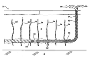
- FIG. 1 is a side cross-sectional view of one embodiment (the “first variation”) of the process of the present invention for fracturing and extracting oil from an underground formation, showing fluid flow through each of the two sets of fissures, namely alternately spaced injection fissures and production fissures;
- FIG. 2 is a perspective view of the embodiment of the invention shown in FIG. 1 ;
- FIG. 3 is a partial cross-sectional view along arrows “A-A” of FIG. 2 ;
- FIGS. 4A-4C show another embodiment of the process of the present invention, commencing with injection of fluid via the fracture at the distal end of the horizontal wellbore and producing from the adjacent fracture and, to a lesser extent , other fractures more proximate the proximal end of the horizontal wellbore( FIG. 4A ), and subsequently moving a plug member toward a proximal (heel) end of the wellbore thereby converting fractures used for production into injection wells ( FIGS. 4B, 4C );
- FIGS. 5A-5C show another embodiment of the process of the present invention similar to the embodiment shown in FIGS. 4A-4C commencing with injection of fluid via the penultimate distal fracture along the horizontal wellbore and producing from the most distal fracture, and subsequently moving a plug member toward the proximal (heel) end of the wellbore and subsequently thereby converting injection fractures into producing fractures ( FIGS. 5B, 5C );
- FIG. 6 is a sectional schematic view of a typical packer element which is used as part of the present process to, upon actuation after being inserted in a production well or injection well, create a seal to thereby isolate individual locations along the respective production well and injection well, to allow fracturing of the formation at discrete intervals along horizontal portions of the injection and production wells;
- FIG. 7 is a cross-sectional view of a typical pressure-actuated sliding sleeve which is used as part of the present process, particularly in open hole configurations, wherein the sliding sleeve is shown in the closed position for insertion into an open hole, and may thereafter through hydraulic fluid pressure applied thereto, cause an aperture therein to open;
- FIG. 8 is a similar sectional view of the pressure-actuated sliding sleeve of FIG. 7 , wherein the sliding sleeve is shown in the position where the aperture is opened;
- FIG. 9 is a graph showing oil production rate in m3/day (y axis) vs. time (days) (x axis) for various configurations allowing comparison of the method of the present invention shown in FIGS. 1-3 compared with the prior art method of producing from all fissures, wherein curve (a) is production without injection of driving fluid, curve (b) is the oil rate using gas fluid drive (methane), curve (c) is the oil rate with 2-years of primary oil production followed by gas injection (methane), and curve (d) is the oil rate where water is used as the injection fluid into alternately spaced fissures;
- FIG. 10 is a graph showing oil recovery factor (y axis) as a percentage of original oil in place (% OOIP) vs. time (days) (x axis) for various configurations allowing comparison of the method of the present invention shown in FIGS. 1-3 compared with the prior art method of producing from all fissures, where line (i) is the % OOIP using primary production methods (ie from the injection and production wells), line (ii) is the % OOIP using gas drive fluid injection in the injection well , line (iii) is the % OOIP with 2-years of primary oil production followed by gas injection, and line (iv) is the % OOIP using water injection;
- FIG. 11 is a depiction of, respectively, two versions of a dual-tubing packer, which can coupled together be used in the method of the present invention in a single well for allowing fluid injection in alternately spaced vertical fissures and recovery of oil from alternately spaced fissures in the formation;
- FIG. 12 is a schematic rendition of the method of the present invention using dual-tubing packers of the type described herein and shown in FIG. 11 , and a single well for allowing fluid injection in alternately spaced vertical fissures and recovery of oil from alternately spaced fissures in the formation;
- FIG. 13 is an enlarged schematic rendition of a formation, using only primary oil recovery, whereby collection is from all fissures/fractures;
- FIG. 14 is a similar enlarged schematic rendition of section of a formation intermediate two alternatingly spaced fractures in accordance with one method of the present invention, wherein the first series of fractures is used as a high pressure injection plane so as to produce high pressure in the region of injection fractures, and the most proximate alternatingly spaced fractures are used as a low pressure and high permeability production plane.
- item 20 indicates a depiction of one method (“the first variation”) of the present invention for recovering hydrocarbons from a multiple-fractured a “tight” subterranean formation 6 possessing a hydrocarbon-containing reservoir, above which is typically a layer of cap rock 1 and below which is typically a layer of bottom rock 2 .
- two wells are drilled into reservoir 6 , namely an injection well 12 having a vertical portion 32 and a horizontal portion 44 , and a production well 8 similarly having a corresponding vertical portion 33 and a horizontal portion 45 .
- the horizontal portion 45 of the production well 8 is drilled parallel to, and proximate, the horizontal portion 44 of injection well 12 , as shown in FIGS. 1 & 2 .
- Horizontal portion 45 may be drilled level with, or alternatively spaced vertically above or below (see FIG. 3 , for example) horizontal portion 44 .
- a liner (not shown) may be inserted into one or both of such wells 8 , 12 , and cemented in place. If a liner is used in production well 8 and injection well 12 , the horizontal portion 45 of production well 8 is perforated at discrete locations 38 therealong using procedures well known to persons of skill in the art, and the horizontal portion 44 of injection well 12 is similarly perforated at (mutually alternating) discrete locations 37 , to allow flow of pressurized fluid into the formation 6 , and collection of hydrocarbons from the formation 6 , as more fully explained below.
- Fracturing of the formation 6 is conducted by injecting pressurized fluid at discrete locations 37 , 38 along the length respectively of horizontal portions 44 , 45 so as to create fissures 5 a , 5 b within formation 6 extending respectively upwardly from such discrete locations 37 , 38 along horizontal portions 44 , 45 respectively.
- discrete locations 37 along length of horizontal portion 44 of injection well 12 are in mutually alternating spaced relationship to those discrete locations 38 extending linearly along the length of the horizontal portion 45 of production wellbore 8 , so as to thereby allow, when pressurized fluid in injected at such discrete locations 37 , 38 , respectively upwardly-extending fissures 5 b , 5 a to be created in formation 6 , in mutually alternating substantially linear relationship, as shown in FIGS. 1 & 2 .
- the fracturing may be conducted by inserting tubing 55 , 56 in each of respective horizontal portions 44 , 45 , wherein each of tubing lines 55 , 56 (which may be continuous tubing or jointed pipe string) possess a number of spaced-apart packer seals 9 along the length thereof.
- Packer seals 9 are well known in the art, and are commercially available from various well-known down-hole tool companies such as Packers Plus Inc. (particularly for un-lined wellbores) and by Halliburton company (particularly for lined and cemented wellbores).
- Packer seals 9 in one embodiment thereof as shown in FIG. 6 , possess a hydraulically-actuated piston 18 .
- tubing 55 , 56 may be hung , respectively, in vertical portions 32 , 33 of injection and production wells 12 , 8 by tubing hangers 30 , 25 , respectively, as shown in FIG. 1 .
- hydraulically-actuated sleeves 15 may be interposed intermediate pairs of packer seals 9 .
- Such sleeves 15 one example of which is shown in detailed view in FIG. 7 (closed position) and FIG. 8 (open position), each possess an aperture 21 , which upon application of hydraulic pressure to interior of sleeve 15 and release of locking ring 42 , causes such aperture 21 to be opened to allow egress of pressurized fluid from within tubing 55 , 56 to flow into the formation 6 so as to cause fracturing and thus create fissures 5 a , 5 b .
- Such sleeves 15 may, along with tubing 55 , 56 , be inserted, when in a closed position as shown in FIG.
- Hydraulically actuated sleeves 15 are likewise commercially available, one such sleeve being available from Packers Plus Inc. of Calgary, Alberta.
- fissures 5 a , 5 b along horizontal portions 44 , 45 respectively may be conducted by the traditional, if not somewhat outdated and more time consuming procedure of the so-called “plug and perf” procedure.
- a single pair of pressure-actuated packer seals 9 are provided at a distal end of tubing, such tubing having a single aperture 21 intermediate said pair of packer seals 9 .
- the pair of packer seals 9 are actuated and thereby deployed to create a seal at various discrete locations 37 , 38 along each of horizontal portions 44 , 45 by pushing (or pulling) such packer seals 9 and tubing along the length of each of said horizontal portions 44 , 45 , and at such time pausing to supply hydraulic fluid at each of the discrete locations 37 , 38 so as to create fissures 5 a , 5 b at each of such locations 37 , 38 respectively therealong.
- the discrete locations 37 in horizontal portion 44 of injection well 12 are in mutually alternating spaced arrangement to the discrete locations 38 in horizontal portion 45 of production well 8 in accordance with the method of the present invention, to thereby provide for the injection of pressurized fluid intermediate and closely proximate, adjacent fissures 5 b as shown in FIGS. 1 & 2 , so as to best be able to re-pressurize such “tight” formation 6 at locations where such repressurization is most useful.
- Fluid which is injected for the purpose of creating fractures/fissures 5 a , 5 b as described above may contain a proppant to maintain the fissures 5 a , 5 b in an expanded position.
- a second fluid containing such proppant may thereafter be injected down-hole via tubing 55 , 56 to maintain the created fissures in an “open” position.
- the same fluid, or even a third fluid, may be used as the driving fluid when carrying out the method of the present invention for sweeping the formation .
- the injectant fills the vertical fractures Sa that are above the injection tubing 55 , by travelling into fissures 5 a via perforations in the well liner (if a well liner is used) at discrete locations 37 along horizontal portion 44 , and rise in fissures Sa whereafter such injectant fluid is forced into the formation 6 and flows laterally towards the adjacent fissures 5 b that are themselves in communication with the production tubing 56 . Reservoir fluids that drain into the production tubing 56 are lifted to the surface, typically by pumping.
- the injectant fluid may be, but is not limited to, the following substances, namely: produced gas, flue gas and others; oxygen-containing gases such as air, oxygen or mixtures thereof in an in situ combustion process; liquids that may or may not be soluble in the reservoir hydrocarbon, such as water, steam or natural gas liquids.
- this process of enhanced hydrocarbon recovery using hydraulically-induced and propped reservoir fractures 5 a 5 b is conducted in the native reservoir without de-pressuring in order to maintain the maximum hydrocarbon mobility.
- the present invention can still be utilized beneficially.
- fissures 5 b Due to the increased pressure in the formation 6 resulting from injection of fluid into the formation via fissures 5 b , hydrocarbons and reservoir fluid present in formation 6 are encouraged and driven toward fissures 5 a interposed between fissures 5 b , as shown in FIGS. 2 & 3 , and thereafter drain downwardly to be collected by production tubing 56 , and thereafter are pumped to surface.
- FIGS. 4A-4C a first embodiment thereof being shown in FIGS. 4A-4C , only a single injection/production well 90 is drilled, having a vertical portion 91 , and a horizontal portion 92 extending outwardly from a lower end of the vertical portion 91 .
- a heel portion 99 is present at the base of the vertical portion 91 , namely at the most proximal end of the horizontal portion 92 , and a toe portion 100 is present at the opposite, most distal end of the horizontal portion 92 .
- Upwardly-extending fissures are created along the length of horizontal portion 92 by injecting a pressurized fluid at a plurality of discrete spaced locations along a length of said horizontal portion 92 .
- the pressurized fluid contains a proppant, or alternatively a proppant is thereafter injected under pressure into said created such fissures and to render said fissures in a propped condition.
- injection tubing 55 is placed in horizontal portion 92 of well 90 .
- Injection tubing 55 as an actuatable packer member 93 , such as shown in FIG. 6 , situated proximate a distal end of said tubing 55 .
- Actuatable packer 93 is adapted, when hydraulically actuated via pressure in tubing 55 , to create a seal between said tubing 55 and said horizontal portion 92 .
- packer 93 and injection tubing 55 is initially situated on a heel side of a most distal upwardly-extending fissure 5 a as shown in FIG. 4A .
- Pressurized fluid 96 is injected into said injection tubing 55 so as to cause said fluid to flow into said most distal upwardly-extending fracture 5 a , and producing oil to surface which flows into an annular area in said wellbore via a penultimate fissure Sb adjacent said most distal upwardly-extending fissure 5 a.
- packer member 93 is deactivated, and tubing 55 and packer member 93 are moved toward the heel 99 , as shown in FIG. 4B .
- Packer member 93 is re-actuated so as to create a seal between injection tubing 55 and wellbore 90 .
- Injection of said fluid 96 is re-commenced so as to inject said fluid 96 into said penultimate upwardly-extending fissure 5 a ′, and producing oil which flows into said annular area via a fissure 5 ′ adjacent said penultimate fissure 5 a ′ on a heel side of said penultimate fissure 5 .
- Such process is further repeated, as shown in FIG. 4C , and thereafter, each time progressively converting successive production fissures 5 b ′′, 5 b ′′′, 5 iv and 5 v to respective production fissures 5 a ′, 5 a ′′, etc. until reaching the heel portion 99 of horizontal portion 92 , when hydrocarbons in such formation 6 will have then been substantially recovered.
- fissures 5 a and 5 b , 5 b ′, 5 ′′, 5 ′′′, 5 b iv and 5 v are created as before, with fissure 5 a being the fissure most proximate the heel portion 99 (ie situated at the proximal end of horizontal portion 92 ), and fissures 5 b , 5 b ′, 5 b ′′, 5 b ′′′, 5 b iv and 5 v extending respectively toward the toe 100 .
- packer member 93 is deactuated, and moved with said injection tubing toward toe portion 100 , where packer member 93 is re-actuated.
- Fluid 96 is again injected into remaining upwardly-extending fissures 5 b ′′, 5 b ′′′, 5 b iv and 5 v , and hydrocarbons which flow into said annular area via said most proximal fissure 5 a and into a further adjacent penultimate fissure 5 a ′, are produced to surface.
- packer 93 is not actuated by pressure within tubing 55 but rather actuated via other means well known to persons of skill in the art, such as by ball-drop methods, which are not needed to be discussed herein
- FIGS. 5A-5C again only a single injection/production well 90 is drilled, and upwardly extending fissures 5 a and 5 b are created along the length of horizontal portion 92 , as shown in FIG. 5A , as per the manner described above.
- Production tubing 55 having an open end 94 and an actuatable packer 93 thereon is situated in horizontal portion 92 , with packer member 93 situated proximate a toe portion 100 , on a heel side of a most distal upwardly-extending fissure 5 b , as shown in FIG. 5A .
- Packer member 93 is actuated to create a seal between tubing 55 and wellbore 90 , and fluid 96 is injected into an annular area intermediate said production tubing 55 and said wellbore 90 and thereby into a penultimate fissure 5 a adjacent said most distal upwardly-extending fissure 5 b , as shown in FIG. 5A .
- Hydrocarbons 95 which drain into said horizontal portion 92 via said most distal upwardly-extending fissure 5 b and which thereafter flow into said production tubing via said opening 94 therein, are produced to surface.
- packer member 93 is de-actuated, and moved along with production tubing 55 towards heel portion 99 , where is re-actuated.
- Injection of fluid 96 is re-commenced, as shown in FIG. 5B , so that fluid is again injected into said annular area so as to now be injected into an upwardly-extending adjacent fissure 5 a on a heel side of a penultimate fissure 5 b ′, and producing oil which flows into said production tubing via said penultimate fissure.
- fissures 5 a and 5 b , 5 b ′, 5 b ′′, , 5 b ′′′, 5 b iv and 5 v are created as before, with fissure 5 a being the fissure most proximate the heel portion 99 (ie situated at the proximal end of horizontal portion 92 ), and fissures 5 b , 5 b ′, 5 b ′′, 5 b ′′′, 5 b iv and 5 v extending respectively toward the toe 100 .
- Production tubing 55 having actuable packer member 93 thereon and an opening 94 at a distal end thereof, is positioned in horizontal portion 92 proximate heel portion 99 .
- Packer 93 is actuated 4 to create a seal between said tubing 55 and said wellbore 90 , on a toe side of a most proximal upwardly-extending fissure 5 a .
- Fluid 96 in into an annular area intermediate said production tubing 55 and said wellbore 90 and thereby injected into said most proximal fissure 5 a , and producing hydrocarbons which drain into said wellbore via said remaining upwardly-extending fissure 5 b and which thereafter flow into said production tubing 55 via said opening 94 therein.
- packer 93 is not actuated by pressure within tubing 55 but rather actuated via other means well known to persons of skill in the art, such as by ball-drop methods, which are not needed to be discussed herein.
- the method of the present invention comprises using dual-tubing packers 12 a , 12 b and a single production/injection wellbore 90 to achieve fluid injection in alternately spaced vertical fissures 5 a and further recovery of oil from alternately spaced recovery fissures 5 b in the formation 6 , and such alternative method using dual-tubing packers 12 a , 12 b is shown schematically in FIG. 12 .
- FIG. 11 An enlarged view of the dual-tubing packers 12 a , 12 b used in this particular method is shown in FIG. 11 .
- the method of the present invention for recovering hydrocarbons from a subterranean formation 6 using fluid injection in alternating hydraulic fractures 5 a , 5 b created in formation 6 , using dual-tubing packers 12 a , 12 b comprises the steps of firstly drilling a single injection/production well 90 in formation 6 , having a vertical portion 91 and a lower horizontal portion 92 extending horizontally outwardly from a lower end of said vertical portion 91 .
- a series of parallel upwardly-extending alternating fissures 5 a , 5 b respectively are created along the horizontal portion 92 of said injection/production well 90 by known fracking methods, such as inserting a series of packers 9 , to thereby create spaced-apart sections 7 , 8 of horizontal portion 92 and allow supply of pressurized fracturing fluid to such isolated sections 7 , 8 so as to create vertical upwardly-extending alternating fissures 5 a , 5 b therefrom at spaced known distances along a length of horizontal portion 92 of injection/production wellbore 90 .
- a dual tubing string 10 , 11 having dual tubing packers 12 a , 12 b spaced therealong may be inserted in the horizontal wellbore 92 thereby placing a plurality of packers 12 a , 12 b each having dual tubing 10 , 11 passing therethrough and coupled together by coupling male threads 13 on each of dual tubings 10 , 11 passing through packer 12 a coupled to and threadably inserted in couplings 14 on packer 12 b , and placing same along said length of said horizontal portion 92 of said injection/production well 90 and alternatingly spacing said packers 12 a , 12 b between said upwardly-extending fissures 5 a , 5 b along said length as shown in FIG.
- One tubing 11 of dual-tubing packers 12 a , 12 b has perforations 15 therein opposite alternatingly-spaced fissures 5 a in injection regions 7 , and the other of said dual tubing 10 having perforations 21 therein opposite remaining alternatingly-spaced fissures 5 b in recovery regions 8 .
- a pressurized fluid is then injected into one of said dual tubing, namely injection tubing 10 and thereby, via apertures 15 therein injected into said fluid injection regions 7 and thus into alternatingly-spaced fissures 5 a along said length of said horizontal portion of said injection/production well.
- hydrocarbons which drain into said alternatingly-spaced fluid recovery regions 8 via other alternatingly-spaced fissures 5 b and thereby into said other of said dual tubing 10 via apertures 21 therein are pumped/produced to surface.
- FIG. 13 shows a prior (unsatisfactory) oil recovery method (not the subject of the present invention), wherein all fissures Sb are used for production.
- FIG. 13 is an enlarged schematic representation of a portion of a formation 1 between two series of fractures 5 b created along the length of the production wellbore 77 , using only primary oil recovery, whereby collection is from all fissures/fractures 5 b .
- two(2) low-pressure permeability production planes 75 are provided, wherein heated oil may drain downwardly into production wellbore 77 for production to surface.
- FIG. 14 depicts a similar enlarged schematic representation of a portion 1 a of a formation 1 , using a method of oil recovery of the present invention.
- FIG. 14 depicts a method where alternatingly-spaced injection fractures Sa and production fractures 5 b are positioned along a length of a production wellbore 77 .
- An injection plane 76 created from fluid such as diluents, heated steam, CO 2 , or viscosity-reducing agents, is injected into injection fractures 5 a .
- Such fluid drives bitumen within the portion 1 a of formation 1 in the single direction of fluid flow vectors 78 namely towards production fissures 5 b , which thereby forms a high permeability (low pressure) production plane 75 within reservoir 1 a , which allows bitumen to drain down into production wellbore 77 for production to surface.
- bitumen is driven (swept) from substantially the entire volume of portion 1 a of formation 1 , and in particular from a larger volume of formation 1 than the volume of the formation that is drained in FIG. 13 , thus increasing efficiency of production from a given volume of formation 1 as compared to the method depicted in FIG. 13 .
- FIGS. 9 & 10 show the oil production rates and Oil Recovery Factors, respectively, over time, for various embodiments of the present invention compared with the prior art “primary” recovery method using production from all created fissures.
- FIG. 9 shows the oil production rate for various configurations as follows:
- curve (a) depicts oil production rate for the primary production method using production from each of the two wells drilled (i.e. from all of the fissures created in the formation) over time, over the period of 11 years (i.e. 4015 days);
- curve (b) depicts oil production rate for the second embodiment of the present invention as a function of time (days), namely primary production from all of the fissures created for a period of 2 years, followed by gas injection into every other fissure and production from the remaining fissures, over the remaining 9 years;
- curve (c) depicts oil production rate for the first embodiment of the present invention as a function of time (days), namely gas injection into every other fissure and production from the remaining fissures, over the period of 11 years;
- curve (d) depicts oil production rate for the second embodiment of the present invention as a function of time (days), namely primary production from all of the fissures created for a period of 2 years, followed by water injection into every other fissure and production from the remaining fissures, over the remaining 9 years.
- curve (a) depicts oil % OOIP for the primary production method using production from each of the two wells drilled (ie from all of the fissures created in the formation) over time, over the period of 11 years (ie 4015 days);
- curve (b) depicts % OOIP for the second embodiment of the present invention as a function of time (days), namely primary production from all of the fissures created for a period of 2 years, followed by gas injection into every other fissure and production from the remaining fissures, over the remaining 9 years;
- curve (c) depicts % OOIP for the first embodiment of the present invention as a function of time (days), namely gas injection into every other fissure and production from the remaining fissures, over the period of 11 years;
- curve (d) depicts oil production rate for the second embodiment of the present invention as a function of time (days), namely production from 1 ⁇ 2 the fissures, with remaining alternating fissures being injected with water.
- Table 2 summarizes additional results from the above tests, including % OOIP obtained from FIG. 10 for arbitrary time periods of 3 years and 11 years, with respect to four(4) different configurations, (i) “Primary”, meaning production from all fissures, without fluid injection in alternate fissures; (ii) “Gas”, meaning production from 1 ⁇ 2 the fissures, with remaining alternating fissures being injected with gas; (iii) “Primary then Gas” meaning initial production from all fissures, followed by production from 1 ⁇ 2 the fissures, with remaining alternating fissures being injected with gas; and (iv) “water”, meaning production from 1 ⁇ 2 the fissures, with remaining alternating fissures being injected with water.
Landscapes
- Engineering & Computer Science (AREA)
- Geology (AREA)
- Life Sciences & Earth Sciences (AREA)
- Mining & Mineral Resources (AREA)
- Environmental & Geological Engineering (AREA)
- Fluid Mechanics (AREA)
- Physics & Mathematics (AREA)
- General Life Sciences & Earth Sciences (AREA)
- Geochemistry & Mineralogy (AREA)
- Mechanical Engineering (AREA)
- Consolidation Of Soil By Introduction Of Solidifying Substances Into Soil (AREA)
- Quick-Acting Or Multi-Walled Pipe Joints (AREA)
- Organic Low-Molecular-Weight Compounds And Preparation Thereof (AREA)
Abstract
A method for enhancing production from multiple-fractured underground “tight” formations. Spaced upwardly-extending injection fissures are created along a horizontal injection wellbore, and upwardly-extending collection fissures, alternately spaced with the injection fissures, are created along the horizontal injection wellbore or another adjacent production wellbore. The injection wellbore is supplied with fluid under pressure, which flows into such created fissures and drives reservoir fluids within the formation to the remaining (alternately) spaced adjacent fissures along such wellbore or another parallel adjacent (production) wellbore, thereby allowing reservoir fluids to flow downwardly along such alternately spaced production fissures for collection. In a refinement, production is carried out initially from both the production and injection wellbores, and upon the rate of production of hydrocarbons slowing, production from the injection wellbore is stopped and a fluid is injected therein and thus into the formation via the alternate spaced fissures, thereby re-pressurizing the formation.
Description
This application is a divisional to U.S. patent application Ser. No. 14/324,061 filed Jul. 3, 2014, which claims priority to Canadian Patent Application No. 2,820,742, filed Jul. 4, 2013, and to Canadian Patent Application No. 2,835,592 filed Nov. 28, 2013, each of which are hereby incorporated by reference in their entirety.
The present invention relates to a fluid-drive hydrocarbon recovery process, and more particularly to a fluid drive process which uses fluid injection in alternating fractures which have been mechanically induced in a subterranean hydrocarbon-containing formation, with oil and/or gas production from the alternating fractures.
Multiple fracturing of oil, gas and coal bed methane-bearing formations, where such formations have low permeability (i.e. “tight” reservoirs) are typically necessary to adequately produce hydrocarbons. Various of such methods are now fully commercialized in the prior art as primary oil and/or gas recovery methods.
Two types of completions for fracturing formations that are currently employed are Packers Plus Energy Services Inc.'s StackFrac™1 process which uses open hole completions, and lined/cemented completions using technology (valves, liners, and the like) supplied by Halliburton Company. A horizontal hole is drilled low in the target consolidated tight-rock hydrocarbon reservoir. In the Halliburton technology, a liner is emplaced in the hole and cemented-in. This assures that there is no direct communication between the future induced fractures along the outside of the wellbore. In the Packers Plus technology, the fractures are accomplished from an open hole-there is no liner. Isolating packer seals (“packers”) situated on injection tubing are actuated down-hole when in the well, so as to press against the rock itself in order to isolate the zones when conducting fracturing operations and create fissures in the rock, which typically extend upwardly from a horizontal wellbore. After the fracturing operation, the packers are deactivated and all fractures then produce to the surface, in a process termed “primary production” which terminology is adopted and used herein. Fractures are kept open by the deposit within the fractures of a “proppant” that has been carried into the fractures by the fracturing fluid. Proppants typically consist of sand, metallic or ceramic balls, and/or various chemicals, and provide a relatively high permeability flow channel. Formation fluids that flow into the fractures then easily drain to production tubing within the horizontal hole or wellbore for conveyance to the surface. 1StacFrac™ is a registered trademark of Packers Plus Energy Services Inc. for inter alia the wares of packers, frac-ports, and ball seats.
A major characteristic and benefit of multiple-induced fractured reservoirs is high initial production rates. Problematically, however, when producing from all fractures simultaneously the production rates for such reservoirs typically suffer rapid decline as pressure drops within the formation, for reasons as explained below. The multiple fracturing process is expensive, and the overall recovery factors for these types of formations are typically low, usually achieving recovery factors of less than 10% for oil. In order to maintain satisfactory field-wide production rates, a vigorous program of capital-intensive drilling of new multiple-fractured wells is required to compensate for the high decline rate. The oil production mechanism is by solution gas drive, and thus there is a rapid decline in the reservoir pressure which is detrimental to the potential future oil recovery. In this regard, as solution gas comes out of solution with declining pressure within the formation, the viscosity of the remaining oil increases because light components are removed from the oil.
Furthermore, two-phases of intermingled oil and gas are established, thereby decreasing the oil relative permeability and further reducing production rates. Consequently the oil flow rate decreases rapidly.
Because hydrocarbons such as shale gas and coal bed methane occur in formations of low permeability, recovery of these types of hydrocarbons particularly suffer from low recovery factors.
What is needed is a hydrocarbon recovery method for use in conjunction with multiple-fractured tight reservoirs, so as to reduce or limit the rapid decline in pressure in the formation which typically results, and to limit the number of needed multiply-fractured wells which are needed in “tight” formations to achieve satisfactory percentage recovery from such formations. In particular, an effective fluid-drive process for formations that have and need multiple-induced fractures, that can be applied as a primary as well as secondary oil recovery method, would be especially beneficial.
In addition to oil and gas reservoirs, a similar problem occurs in tight coal-bed methane formations. Methane is adsorbed on the coal, and is recovered by de-pressuring the formation, which provides only partial release of the methane from the coal surface. What is needed is an effective fluid drive process, ideally using CO2, which adsorbs much more strongly than methane.
US 2013/0048279 as best seen from FIG. 3 thereof, teaches two parallel vertical wells, a second placed a distance from the first, wherein the mechanism to produce oil or gas from the formation is located at the second well.
US 20120168182 and US 20080087425 both teach inter alia a method for producing oil and/or gas comprising injecting a miscible enhanced oil recovery formulation into fractures of a formation for a first time period from a first well; producing oil and/or gas from the fractures, from a second well for the first time period; injecting a miscible enhanced oil recovery formulation into the fractures for a second time period from the second well; and producing oil and/or gas from the fractures from the first well for the second time period.
US 2006/0289157 teaches a process using gas-assisted gravity drainage, comprising placing one or more horizontal producer wells near the bottom of a pay zone of a subterranean hydrocarbon-bearing reservoir and injecting a fluid displacer such as CO2 through one or more vertical wells or horizontal wells. Pre-existing vertical wells may be used to inject the fluid displacer into the reservoir. As the fluid displacer is injected into the top portion of the reservoir, it forms a gas zone, which displaces oil and water downward towards the horizontal producer well(s).
US 2006/0180306 teaches a method for recovering crude oil from subterranean reservoirs by injecting both water and a second less dense fluid to displace the oil, preferably through horizontal wells.
U.S. Pat. No. 8,122,953 teaches inter alia a method of improving production of fluid from a subterranean formation including the step of propagating a generally vertical inclusion into the formation, from a generally horizontal wellbore intersecting the formation.
U.S. Pat. No. 7,441,603 teaches a method for recovery of oil from impermeable oil sands, comprising providing vertical fractures using horizontal or vertical wells. The same or other wells are used to inject heated pressurized fluids and to return the cooled fluid for reheating and recycling. The heat transferred to the oil shale gradually matures the kerogen to oil and gas as the temperature in the shale is brought up, and also promotes permeability within the shale in the form of small fractures sufficient to allow the shale to flow into the well fractures
U.S. Pat. No. 7,069,990 teaches a process for enhanced oil recovery, comprises providing at least one production well and one injection well; and injecting into the target stratum a slurry formed from sand, viscous liquids or oily sludge, which is delivered at or near formation fracture pressures. Monitoring of bottom hole pressure is carried out, to permit delivery of the slurried wastes in a series of injection episodes.
U.S. Pat. No. 4,733,726 teaches a method for recovery of oil, which provides injection of steam via an injection well into the formation and oil is recovered until there is steam breakthrough at the production well. Thereafter, the production well may be shut in or throttled while continuing injection of the steam until the bottom-hole injection pressure is greater than the vertical pressure created by the overburden thereby causing the formation to fracture horizontally. A third cycle is initiated in which oil is recovered from the formation from either the production well or the injection well or both until the amount of oil recovered is unfavorable.
U.S. Pat. No. 4,687,059 teaches injection of water into a subterranean formation followed by the injection of a polymer solution to drive oil toward a production well. The polymer solution may thermoelastically fracture the formation behind an oil-water bank to increase the injectivity rate.
U.S. Pat. No. 4,068,717 teaches a oil recovery process by injecting steam into an injection well penetrating the reservoir sufficiently to fracture the tar sand and provide passage for the steam through the tar sand to a production well piercing a tar sand reservoir.
None of the above prior art, however, teaches anything about creating, in alternating arrangement, injection fissures and producing fissures, to sweep a formation.
What is needed is a hydrocarbon recovery method for use in conjunction with multiple-fractured tight reservoirs, so as to reduce or limit the rapid decline in pressure in the formation which typically results, and to limit the number of needed multiply-fractured wells which are needed in “tight” formations to achieve satisfactory percentage recovery from such formations. In particular, an effective fluid-drive process for formations that have multiple-induced fractures, that can be applied as a primary as well as secondary oil recovery method, would be especially beneficial.
To improve both production rate and percentage recovery from “tight” formations, and in particular from multiple-fractured wells, in one embodiment the present invention provides for the creation of multiple-induced fractures in a hydrocarbon formation but in particular in two alternating groups, namely injection fractures and producing fractures, which are situated in linear alternating arrangement, when approximately ½ of the fractures are used as injection means and the remaining ½ of the fractures used a production means to recover hydrocarbons. Such method provides an efficient fluid drive to effectively sweep the formation and drive hydrocarbons into adjacent alternating fissures for subsequent collection. The present method in such embodiment improves recovery from a formation by providing a fluid drive via alternate adjacent fissures in the formation, with remaining alternately spaced fissures being used for production.
Specifically, with methods which employ primary oil recovery by solution gas drive (for example using a vertical injector well for injecting a gas into the formation but not using alternating fractures as injectors and collector channels as described above and below) and particularly with “tight” formations, as mentioned above typically results in rapid decline in pressure of the formation, causing a corresponding rapid decline in production.
Conversely, with the method of the present invention, a high-pressure and high permeability injection plane [i.e. the alternatingly spaced fissures located adjacent alternatingly spaced production channels (fissures)] is provided, which then allows a sweep of areas of the reservoir proximate the high permeability injection planes to thereby cause a fluid flow vectors within the formation from the high permeability injection plane in the direction of the alternatingly-spaced production channels (fissures), and consequent improved sweep of the formation through directed sweep process.
The methods herein are adapted for use in oil and gas containing reservoirs, and are also particularly suited for a particular type of gas-bearing formation, namely coal-bed methane formations, where the driving fluid in the method of the present invention using alternating injection and recovery channels is CO2, and which CO2 driving fluid advantageously replaces methane on the coal surface and sweeps it to a proximate adjacent production well. Advantageously, where CO2 is used as a driving fluid in accordance with the method of the present invention, such method advantageously provides for carbon sequestration in the form of subterranean sequestration of the CO2.
Specifically, in a further aspect of the invention, a well completion method is provided in which a plurality of expandable packers are used.
In a first embodiment, vertical fractures are established from a horizontally-drilled open hole or from a cemented liner therein. Thereafter, a dual tubing (in the form of continuous tubing or segmented pipe) with spaced-apart isolation packers is run into the open hole or cemented liner. The spaced-apart packers on the tubing are located between the fractures. Once the packers are expanded against the hole or liner, the fractures will be isolated from each other within the hole or liner. One of the tubings has perforations opposite alternating fractures, and the other tubing has perforations opposite the remaining fractures. In this way, one tubing string can be employed as an injection tubing in fluid communication with the alternating injection fractures, and the other as a production tubing in fluid communication with the remaining (alternating) producing fractures.
Accordingly, in said first embodiment of the method of the present invention for recovering hydrocarbons from a subterranean formation using fluid injection in alternating fissures in said formation, using dual tubing packers, such method comprises the steps of:
-
- (i) drilling a single injection/production well in said formation, having a vertical portion and a lower horizontal portion extending horizontally outwardly from a lower end of said vertical portion;
- (ii) fracturing the formation along said horizontal portion of said injection/production well and creating a plurality of upwardly-extending fissures extending upwardly from, and situated along a length of, said horizontal portion;
- (iii) placing a plurality of packers each having dual tubing therein along said length of said horizontal portion of said injection/production well and alternatingly spacing said packers between said upwardly-extending fissures along said length thereby partitioning said length into alternatingly-spaced fluid injection regions and fluid recovery regions, one of said dual tubing having perforations therein opposite alternatingly-spaced fissures and the other of said dual tubing having perforations therein opposite remaining alternatingly-spaced fissures;
- (iv) injecting a pressurized fluid into one of said dual tubing and thereby injecting pressurized fluid into said fluid injection regions and thus into alternatingly-spaced fissures along said length of said horizontal portion of said injection/production well; and
- (v) producing said hydrocarbons which drain into said alternatingly-spaced fluid recovery regions via other alternatingly-spaced fissures from said other of said dual tubing.
The fissures may be created prior to inserting the dual-tubing packers in the wellbore. Alternatively, they may be created after inserting dual-tubing packers into the horizontal portion of the injection/production well, and pressurized fluid initially supplied to both of the dual tubings to thereby hydraulically fracture the formation and create uniformly spaced fissures along the wellbore. Thereafter, pressurized fluid is only supplied to ½ of the created fissures (i.e. to every other fissure along the length of the horizontal portion of the wellbore), and remaining alternately spaced fissures allow hydrocarbons to drain downwardly into a corresponding fluid recovery region of the injection/production well, and thereafter be produced to surface by the other of the dual tubing.
One example of dual-tubing packers which may be suitable for use in this embodiment process of the present invention, at least in a cased wellbore, are dual-tubing packers, namely GT™2 Dual-String Retrievable Packer, Product Family Nos. H78509 (Standard Service) and H78510 (NACE Service) manufactured by Baker Hughes Corporation, for use in 7 inch (177.8 mm) o.d. (outside diameter) casing, 7⅝ inch (193.7 mm) o.d. casing, or 9 5/5 inch (244.5 mm) o.d. casing. Other suitable dual-tubing packers for use in this process, both in cased and uncased wellbores, will now occur to persons of skill in the art. 2GT is a trademark of Baker Hughes Corporation for a dual-tubing packer.
In a most preferred embodiment, a chosen fluid (a gas or liquid) is injected through the injection tubing. The fluid rises in the formation via each alternate injection fissures which generally extend vertically upwardly from horizontal wells. Such injected fluid then sweeps the reservoir fluid laterally in the formation towards the adjacent producing fissures on each side, whence drainage will be established down into the production tubing for subsequent production of such formation fluids to surface.
In an alternate embodiment of the invention (the “first variation”), instead of utilizing a dual-tubing within a single wellbore which dual tubing comprises respectively the injection tubing and the production tubing, such embodiment provides for use of two (2) separately-drilled horizontal wells, namely an injection well and a production well, each parallel to the other and in close proximity to the other, wherein one of such horizontal wells is used for supplying a pressurized fluid to upwardly-extending fissures which have been created along a horizontal length of a such injection well, and the other well is used as the production well for fractures that have been created along such remaining horizontal well that are alternately spaced and are interdigitated between alternate fissures created along the injection well. Specifically, upwardly extending substantially vertical injection fractures/fissures are established along the horizontal portion of the injection well. Vertical fractures/fissures are also likewise established along the horizontal portion of the production well, but these fractures are laterally offset from the fractures established form the injection well. In other words, scanning horizontally across the formation, the intercepted fractures are alternatively fluid-injection fractures and producing fractures. Production occurs by a fluid being injected via the injection well into fissures along such horizontal (injection) well, and reservoir fluids are then driven into alternately spaced fissures previously created along the horizontal production well, which reservoir fluids then flow downwardly and are collected in production tubing within the production well. Advantageously in such manner the injected fluid is injected in the formation where it may most easily and directly carry out its intended purpose, namely to best direct reservoir fluids into alternately spaced adjacent fissures within the formation, which thereby drain downwardly. Such reservoir fluids, after draining downwardly in said alternately-spaced fissures, are recovered by the production tubing in the production well and produced to surface.
The lateral separation distance between various adjacent sequential injection and production fractures/fissures may vary, or may be constant, and will be selected based on standard reservoir engineering analysis of the properties of the formation obtained through various known and widely used well logging techniques, and will depend on reservoir parameters along the wells, such as but not limited to, matrix permeability, matrix fracture pressure, produced hydrocarbon mobility, injectivity of the injection fluid, and desired injection and production rates. Numerical simulation using software such as licensed by the Computer Modelling Group of Calgary, Alberta, Canada can assist in the selection of injection fluid and determination of lateral offset of the individual injection and production fractures relative to each other.
Accordingly, in a broad alternate aspect, the process of the present invention comprises a process for recovering hydrocarbon from a subterranean formation utilizing propped hydraulic fractures, comprising the steps of:
-
- (i) drilling an injection well having a vertical portion and a horizontal portion extending horizontally outwardly from a lower end of said vertical portion thereof;
- (ii) drilling a production well having a vertical portion and a horizontal portion extending outwardly from a lower end of said vertical portion thereof, wherein said horizontal portion of said production well is situated parallel to said horizontal portion of said injection well;
- (iii) creating upwardly-extending fissures in the formation along each of said horizontal portions of said production well and injection well by injecting a pressurized fluid into each of said production well and injection well, at a plurality of discrete locations along a length of each of said horizontal portion of each of said production well and injection well, wherein said discrete locations in said production well substantially correspond in number to said discrete locations in said injection well and wherein said discrete locations and each of said respective fissures extending upwardly along said injection well are in alternating linear spacing and substantially mutually adjacent relation with corresponding respective fissures extending upwardly along said horizontal portion of said production well;
- (iv) said pressurized fluid containing a proppant, or alternatively after step (ii) above injecting a proppant under pressure into said created fissures to render said fissures in a propped condition; and
- (v) continuing to inject said pressurized fluid, or injecting another fluid, into said injection well and thereby into said fissures above said injection well and thence into said formation thereby pressurizing said formation and causing said hydrocarbons within said formation to be driven into said fissures above said production well, and to drain downwardly therein into said horizontal portion of said production well; and
- (vi) producing said hydrocarbons which collect in said horizontal portion of said production well to surface.
In a similar embodiment of the invention, the invention comprises a process for recovering hydrocarbons from a subterranean formation utilizing propped hydraulic fractures comprising the steps of:
-
- (i) drilling an injection well, having a vertical portion and a horizontal portion extending horizontally outwardly from a lower end of said vertical portion along a lower portion of the formation;
- (ii) drilling a production well having a vertical portion and a horizontal portion extending outwardly from a lower end of said vertical portion, wherein said horizontal portion of said production well is situated proximate to, parallel with, and spaced apart from, said horizontal portion of said injection well;
- (iii) fracturing the formation along each of said production well and injection well and creating a plurality of upwardly-extending fissures extending upwardly from, and situated along a length of, said horizontal portion of each of said injection well and said production well, said upwardly-extending fissures created along said injection well mutually alternating along said horizontal length thereof with upwardly-extending fractures situated along said production well;
- (iv) utilizing injection tubing, having therealong a plurality of spaced-apart packer seals within a length of said horizontal portion of said injection well, said injection tubing further having apertures or apertures which may be opened intermediate pairs of said spaced-apart packer seals situated at locations at which said upwardly-extending fractures are located along said injection well, and injecting a pressurized fluid into said injection tubing and into said fissures extending along said horizontal portion of said injection well;
- (v) utilizing production tubing , having therealong a plurality of spaced-apart packer seals similarly spaced apart as per said packer seals along said injection tubing, said production tubing further having apertures, or apertures which may be opened, intermediate pairs of said spaced-apart packer seals, along a length of said horizontal portion of said production well, wherein said apertures in said production tubing are positioned in alternating and non-lateral alignment with said apertures located in said injection tubing, and collecting from said formation hydrocarbons in said production tubing which flow into said fissures and which drain downwardly into said production tubing via said apertures therein; and
- (vi) producing the hydrocarbons which collect in said production tubing to surface.
The above method may be used wherein the injection well is an open hole, or one where a liner is used. Where a liner is used, packer seals need not be used, but the hole must be lined and cemented , otherwise the first wellbore will fill with injection fluid when the second wellbore is fractured. Specifically, where a lined well(s) are desired and no packer seals are therefore needed, the above method is further modified, wherein:
-
- (a) step (i) above further comprises the step of inserting and cementing a liner in the injection well;
- (b) step (ii) further comprises the step of inserting and cementing a liner in said production well;
- (c) adding a step, after step (ii), of creating perforations in said liner and cement in each of said horizontal portions of said production and injection wells, at a plurality of discrete allocations therealong, wherein said discrete locations in said production well are approximately equal in number but linearly alternating with said corresponding perforations created in said cemented liner in said injection well.
Alternatively to the above methods, a two-step process may be undertaken. Specifically, after creating the fractures along each of the production well and injection wells in the manner described above, both the production well and injection wells are initially put on production as is traditionally done, producing reservoir fluids which drain downwardly from all fissures (primary production). Thereafter, namely at a point in time when production rates typically drop off and start to become uneconomical as typically occurs in multiple-fractured “tight” formations, production from the injection well is stopped, and a fluid is then injected into alternate fissures via tubing within the injection well, to thereby begin the fluid drive process described above, with fluid production continuing from remaining alternately spaced fissures in the formation. In such manner the production rate can be restored to similar earlier levels, and the overall recovery from the formation increased.
Accordingly, in accordance with the above two-step process, in one embodiment thereof such process comprises a process for recovering hydrocarbons from a subterranean formation utilizing propped hydraulic fractures comprising the steps of:
-
- (i) drilling an injection well, having a vertical portion and a horizontal portion extending horizontally outwardly from a lower end of said vertical portion;
- (ii) inserting tubing, having therealong a plurality of spaced-apart packer seals, within a length of said horizontal portion of said injection well, said tubing further having apertures or apertures which may be opened intermediate pairs of said spaced-apart packer seals;
- (iii) drilling a production well proximate said injection well, having a vertical portion and a horizontal portion extending outwardly from a lower end of said vertical portion, wherein said horizontal portion of said production well is situated proximate to, parallel with, and spaced apart from, said horizontal portion of said injection well;
- (iv) inserting tubing , having therealong a plurality of spaced-apart packer seals similarly spaced apart as per said packer seals in said injection well, said tubing further having apertures, or apertures which may be opened, at locations intermediate pairs of said spaced-apart packer seals, along a length of said horizontal portion of said production well, wherein said apertures in said tubing in said production well are positioned in non-lateral alignment with said apertures in said injection well;
- (v) setting, if necessary, said packer seals in each of said respective horizontal portions of said injection well and said production well so as to prevent flow of fluid along an annular passage intermediate said tubing and said production well and injection well, respectively;
- (vi) injecting into said injection well, a fluid under pressure and causing said fluid to flow into said formation via said apertures in said tubing therein, so as to create upwardly extending fissures at each of said apertures along said injection well;
- (vi) injecting into said production well, a fluid under pressure and causing said fluid to flow into said formation via said apertures in said tubing therein , so as to create upwardly extending fissures at each of said apertures along said production well;
- (vii) after step (vi) collecting , via said tubing in said horizontal portion of said production well and said horizontal portion of said injection well, said hydrocarbons which flow into said fissures and which drain downwardly into said tubing in said production well and said injection well;
- (ix) after a period of time and when production from said production well and said injection well decreases to an unsatisfactory rate, injecting a fluid into said injection well and into said upwardly-extending fissures along said injection well; and
- (x) continuing to collect , via said horizontal portion of said production well, said hydrocarbons which flow into said fissures above said production well and which drains downwardly into said tubing in said production well .
In a variation of the present invention (the “second variation”), only a single (injection/production) well is drilled, and pairs of adjacent fissures are used as an injection fissure and an adjacent production fissure, respectively , with fluid in the injection fissure forcing hydrocarbons in the formation to the production fissure. Thereafter, either the production fissure is converted into an injection fissure by injection of fluids therein, or the injection fissure is converted into a production fissure, and a “sweeping” method is used as set out below.
Specifically, in a first embodiment of such second variation, after production for a time from a production fissure, production of hydrocarbons from said production fissure is ceased, and such fissure subsequently used, in the manner described below, as an injection fissure, and fluids injected therein drive hydrocarbons to another (other) adjacent production fissure(s).
Accordingly, in such first embodiment of this second variation, such method comprises a process for recovering hydrocarbons from a subterranean formation utilizing propped hydraulic fractures comprising the steps of:
-
- (i) drilling an injection/production well, having a vertical portion and a horizontal portion extending horizontally outwardly from a lower end of said vertical portion, said horizontal portion having a heel portion proximate said vertical portion, and a toe portion proximate a distal end of said horizontal portion;
- (ii) creating upwardly-extending fissures in the formation along said horizontal portion by injecting a pressurized fluid at a plurality of discrete spaced locations along a length of said horizontal portion ;
- (iv) said pressurized fluid containing a proppant, or alternatively after step (ii) above injecting a proppant under pressure into said created fissures to render said fissures in a propped condition; and
- (v) positioning injection tubing into said wellbore, said injection tubing having an actuatable packer member proximate a distal end of said tubing adapted when actuated to create a seal between said tubing and said wellbore, and situating such packer member and injection tubing within said wellbore on a heel side of a most distal upwardly-extending fissure;
- (vi) injecting said pressurized fluid, or injecting another fluid, into said injection tubing so as to cause said fluid to flow into said most distal upwardly-extending fracture, and producing oil to surface which flows into an annular area in said wellbore via a penultimate fissure adjacent said most distal upwardly-extending fissure;
- (vii) deactivating said packer member and moving said packer member and injection tubing toward said vertical portion, and re-instituting injection of said fluid so as to inject said fluid into said penultimate upwardly-extending fissure, and producing oil which flows into said annular area via a fissure adjacent said penultimate fissure on a heel side of said penultimate fissure.
Of course, rather than commencing at the toe portion and initially injecting fluid into the most distal upwardly extending fracture, commencing at the heel, such method may be similarly employed by instead initially injecting through the most proximal upwardly-extending fissure which is proximate the heel, and thereafter progressing in the manner described above toward the toe.
Accordingly, in such alternate process, such comprises the steps of:
-
- (i) drilling an injection/production well, having a vertical portion and a horizontal portion extending horizontally outwardly from a lower end of said vertical portion, said horizontal portion having a heel portion proximate said vertical portion, and a toe portion proximate a distal end of said horizontal portion ;
- (ii) creating upwardly-extending fissures in the formation along said horizontal portion by injecting a pressurized fluid at a plurality of discrete spaced locations along a length of said horizontal portion ;
- (iv) said pressurized fluid containing a proppant, or alternatively after step (ii) above injecting a proppant under pressure into said created fissures to render said fissures in a propped condition; and
- (v) positioning injection tubing into said wellbore , said injection tubing having an actuatable packer member proximate a distal end of said tubing adapted when actuated to create a seal between said tubing and said wellbore, and situating said packer member and injection tubing within said wellbore on a toe side of a most proximal upwardly-extending fissure;
- (vi) actuating said packer member and injecting said pressurized fluid, or injecting another fluid, into said injection tubing so as to cause said fluid to flow into one or more of remaining upwardly-extending fissures, and producing oil to surface which flows into an annular area in said wellbore via said most proximal fissure;
- (vii) de-actuating said packer member and moving said packer member and injection tubing toward said toe portion, re-activating said packer member and re-instituting injection of said fluid, and injecting said fluid into remaining upwardly-extending fissures, and producing oil which flows into said annular area via said most proximal fissure and a further adjacent penultimate fissure.
In a second embodiment of the above second variation, after injection of fluid for a time into an injection fissure has occurred, injection of fluids into said injection fissure is ceased, and such fissure subsequently used, in the manner described below, as a production fissure which has hydrocarbons driven to such converted fissure via fluid injected into the formation via another (other) injection fissures.
Accordingly, in such second embodiment of this second variation, such method comprises a process for recovering hydrocarbons from a subterranean formation utilizing propped hydraulic fractures which are employed as production channels and subsequently as injection channels, comprising the steps of:
-
- (i) drilling an injection/production well, having a vertical portion and a horizontal portion extending horizontally outwardly from a lower end of said vertical portion, said horizontal portion having a heel portion proximate said vertical portion, and a toe portion proximate a distal end thereof;
- (ii) creating upwardly-extending fissures in the formation along said horizontal portion by injecting a pressurized fluid at a plurality of discrete spaced locations along a length of said horizontal portion;
- (iv) said pressurized fluid containing a proppant, or alternatively after step (ii) above injecting a proppant under pressure into said created fissures to render said fissures in a propped condition; and
- (v) positioning production tubing into said wellbore, said production tubing having an opening and an actuatable packer member thereon proximate a distal end thereof adapted when actuated to create a seal between said tubing and said wellbore, and situating said packer member proximate a toe region of said wellbore on a heel side of a most distal upwardly-extending fissure;
- (vi) actuating said packer member and injecting said pressurized fluid, or injecting another fluid, into an annular area intermediate said production tubing and said wellbore and thereby injecting said fluid into a penultimate fissure adjacent said most distal upwardly-extending fracture, and producing hydrocarbons via said production tubing which drain into said wellbore via said most distal upwardly-extending fissure and which thereafter flow into said production tubing via said opening therein;
- (vii) deactuating said packer member and moving said packer member and production tubing toward said heel portion, re-actuating said packer member and re-instituting injection of said fluid into said annular area so as to inject said fluid into an upwardly-extending adjacent fissure on a heel side of said penultimate fissure, and producing oil which flows into said production tubing via said penultimate fissure.
Again, rather than commencing at the toe portion and initially producing from the most distal upwardly extending fracture, such method may be modified to commence at the heel, such method may be similarly employed by instead initially injecting through the most proximal upwardly-extending fissure which is proximate the heel, and thereafter progressing in the manner described above toward the toe.
In such aspect of the second variation, such method comprises the steps of:
-
- (i) drilling an injection/production well, having a vertical portion and a horizontal portion extending horizontally outwardly from a lower end of said vertical portion, said horizontal portion having a heel portion proximate said vertical portion, and a toe portion proximate a distal end thereof;
- (ii) creating upwardly-extending fissures in the formation along said horizontal portion by injecting a pressurized fluid at a plurality of discrete spaced locations along a length of said horizontal portion;
- (iv) said pressurized fluid containing a proppant, or alternatively after step (ii) above injecting a proppant under pressure into said created fissures to render said fissures in a propped condition; and
- (v) positioning production tubing in said wellbore , said production tubing having an opening and an actuatable packer member thereon proximate a distal end thereof adapted when actuated to create a seal between said tubing and said wellbore, and situating said packer member proximate a heel portion of said wellbore on a toe side of a most proximal upwardly-extending fissure ;
- (vi) actuating said packer member and injecting said pressurized fluid, or injecting another fluid, into an annular area intermediate said production tubing and said wellbore and thereby injecting said fluid into said most proximal fissure adjacent, and producing hydrocarbons via said production tubing which drain into said wellbore via said remaining upwardly-extending fissure and which thereafter flow into said production tubing via said opening therein;
- (vii) deactuating said packer member and moving said packer member and production tubing toward said toe portion, re-actuating said packer member and re-instituting injection of said fluid into said annular area so as to inject said fluid into a penultimate upwardly-extending fissure on a heel side of said most proximal fissure, and producing oil which flows into said production tubing via an adjacent remaining fissure.
In all embodiments of the method of the present invention the hydrocarbon recovered is preferably oil or gas.
In a refinement of the above methods, the recovered hydrocarbon is methane, and the injected fluid is CO2.
In a further refinement, the injected fluid is miscible or immiscible in the hydrocarbon contained within the formation which is being recovered.
In a still further embodiment, the injected fluid is a gas, such as CO2 or water vapour, or alternatively is a liquid such as water.
In a further embodiment, the injected fluid contains oxygen, for use in an in-situ combustion process.
With reference to FIGS. 1, 2 , & 3, item 20 indicates a depiction of one method (“the first variation”) of the present invention for recovering hydrocarbons from a multiple-fractured a “tight” subterranean formation 6 possessing a hydrocarbon-containing reservoir, above which is typically a layer of cap rock 1 and below which is typically a layer of bottom rock 2.
Thus in such first variation two wells are drilled into reservoir 6, namely an injection well 12 having a vertical portion 32 and a horizontal portion 44, and a production well 8 similarly having a corresponding vertical portion 33 and a horizontal portion 45.
The horizontal portion 45 of the production well 8 is drilled parallel to, and proximate, the horizontal portion 44 of injection well 12, as shown in FIGS. 1 & 2 . Horizontal portion 45 may be drilled level with, or alternatively spaced vertically above or below (see FIG. 3 , for example) horizontal portion 44.
A liner (not shown) may be inserted into one or both of such wells 8, 12, and cemented in place. If a liner is used in production well 8 and injection well 12, the horizontal portion 45 of production well 8 is perforated at discrete locations 38 therealong using procedures well known to persons of skill in the art, and the horizontal portion 44 of injection well 12 is similarly perforated at (mutually alternating) discrete locations 37, to allow flow of pressurized fluid into the formation 6, and collection of hydrocarbons from the formation 6, as more fully explained below.
Fracturing of the formation 6 is conducted by injecting pressurized fluid at discrete locations 37, 38 along the length respectively of horizontal portions 44, 45 so as to create fissures 5 a, 5 b within formation 6 extending respectively upwardly from such discrete locations 37, 38 along horizontal portions 44, 45 respectively.
Importantly, discrete locations 37 along length of horizontal portion 44 of injection well 12 are in mutually alternating spaced relationship to those discrete locations 38 extending linearly along the length of the horizontal portion 45 of production wellbore 8, so as to thereby allow, when pressurized fluid in injected at such discrete locations 37,38, respectively upwardly-extending fissures 5 b, 5 a to be created in formation 6, in mutually alternating substantially linear relationship, as shown in FIGS. 1 & 2 .
The fracturing may be conducted by inserting tubing 55, 56 in each of respective horizontal portions 44, 45, wherein each of tubing lines 55, 56 (which may be continuous tubing or jointed pipe string) possess a number of spaced-apart packer seals 9 along the length thereof. Packer seals 9, one example of which is depicted in FIG. 6 , are well known in the art, and are commercially available from various well-known down-hole tool companies such as Packers Plus Inc. (particularly for un-lined wellbores) and by Halliburton company (particularly for lined and cemented wellbores). Packer seals 9, in one embodiment thereof as shown in FIG. 6 , possess a hydraulically-actuated piston 18. When pressurized fluid is supplied to tubing lines 55, 56 to which such packer seals 9 are operatively coupled, such pressurized oil flows through ports 22 where it acts on dual pistons 18 which then laterally compress and causes radial expansion outwardly of a resilient material 17 (see FIG. 6 ), which resilient material 17 then creates a seal between horizontal wellbore 44, 45 (or tubing liner, as the case may be) and tubing 55, 56 respectively.
With reference to FIGS. 1-3 , tubing 55, 56 may be hung , respectively, in vertical portions 32, 33 of injection and production wells 12, 8 by tubing hangers 30, 25, respectively, as shown in FIG. 1 .
When elongate tubing 55, 56 is used, hydraulically-actuated sleeves 15 may be interposed intermediate pairs of packer seals 9. Such sleeves 15, one example of which is shown in detailed view in FIG. 7 (closed position) and FIG. 8 (open position), each possess an aperture 21, which upon application of hydraulic pressure to interior of sleeve 15 and release of locking ring 42, causes such aperture 21 to be opened to allow egress of pressurized fluid from within tubing 55, 56 to flow into the formation 6 so as to cause fracturing and thus create fissures 5 a, 5 b. Such sleeves 15 may, along with tubing 55, 56, be inserted, when in a closed position as shown in FIG. 7 , down into respective horizontal portions 44,45, and when in a desired location 37, 38, be actuated via hydraulic pressure to cause sleeves 15 to expose apertures 21 (see FIG. 8 ), thereby allowing such pressurized hydraulic fluid to be exposed to the formation, thereby creating fissures 5 a, 5 b. Hydraulically actuated sleeves 15 are likewise commercially available, one such sleeve being available from Packers Plus Inc. of Calgary, Alberta.
Alternatively, creation of fissures 5 a, 5 b along horizontal portions 44, 45 respectively may be conducted by the traditional, if not somewhat outdated and more time consuming procedure of the so-called “plug and perf” procedure. In such procedure, a single pair of pressure-actuated packer seals 9 are provided at a distal end of tubing, such tubing having a single aperture 21 intermediate said pair of packer seals 9. The pair of packer seals 9 are actuated and thereby deployed to create a seal at various discrete locations 37,38 along each of horizontal portions 44, 45 by pushing (or pulling) such packer seals 9 and tubing along the length of each of said horizontal portions 44, 45, and at such time pausing to supply hydraulic fluid at each of the discrete locations 37,38 so as to create fissures 5 a, 5 b at each of such locations 37, 38 respectively therealong. Again, the discrete locations 37 in horizontal portion 44 of injection well 12 are in mutually alternating spaced arrangement to the discrete locations 38 in horizontal portion 45 of production well 8 in accordance with the method of the present invention, to thereby provide for the injection of pressurized fluid intermediate and closely proximate, adjacent fissures 5 b as shown in FIGS. 1 & 2 , so as to best be able to re-pressurize such “tight” formation 6 at locations where such repressurization is most useful.
Fluid which is injected for the purpose of creating fractures/fissures 5 a, 5 b as described above may contain a proppant to maintain the fissures 5 a, 5 b in an expanded position. Alternatively, after creation of such fissures 5 a, 5 b, a second fluid containing such proppant may thereafter be injected down-hole via tubing 55, 56 to maintain the created fissures in an “open” position.
The same fluid, or even a third fluid, may be used as the driving fluid when carrying out the method of the present invention for sweeping the formation .
Upon creating of fissures 5 a, 5 b in formation 6 , should no tubing such as tubing 55, 56 with associated packer seals 9 and sliding sleeves 15 have been previously used in fracturing and remain in place in horizontal portions 44, 45, such a tubing string 55, 56, and associated packer seals 9 and associated sleeves 15 are inserted in each of horizontal portions 44, 45. Packer seals 9 are then actuated, and adjacent fissures 5 a, 5 b thereby isolated from each other. An injection fluid is injected through the injection tubing 55. The injectant fills the vertical fractures Sa that are above the injection tubing 55, by travelling into fissures 5 a via perforations in the well liner (if a well liner is used) at discrete locations 37 along horizontal portion 44, and rise in fissures Sa whereafter such injectant fluid is forced into the formation 6 and flows laterally towards the adjacent fissures 5 b that are themselves in communication with the production tubing 56. Reservoir fluids that drain into the production tubing 56 are lifted to the surface, typically by pumping. The injectant fluid may be, but is not limited to, the following substances, namely: produced gas, flue gas and others; oxygen-containing gases such as air, oxygen or mixtures thereof in an in situ combustion process; liquids that may or may not be soluble in the reservoir hydrocarbon, such as water, steam or natural gas liquids.
In a preferred embodiment, this process of enhanced hydrocarbon recovery using hydraulically-induced and propped reservoir fractures 5 a 5 b is conducted in the native reservoir without de-pressuring in order to maintain the maximum hydrocarbon mobility. However, there will be occasions when the well operator will desire to conduct traditional primary petroleum production first, or where the reservoir has already been de-pressured, but nevertheless the present invention can still be utilized beneficially.
Due to the increased pressure in the formation 6 resulting from injection of fluid into the formation via fissures 5 b, hydrocarbons and reservoir fluid present in formation 6 are encouraged and driven toward fissures 5 a interposed between fissures 5 b, as shown in FIGS. 2 & 3 , and thereafter drain downwardly to be collected by production tubing 56, and thereafter are pumped to surface.
In a refinement of the above method, immediately upon creation of the fissures 5 a, 5 b along each of horizontal portions 44, 45 respectively, no injection of fluid is commenced in the injection well 12, and instead all fissures 5 a, 5 b are allowed to receive hydrocarbon fluids from the formation 6. Both the injection well 12 and the production well 8 used to collect and produce hydrocarbons to surface. After a period of time wherein ambient pressure in formation 6 has become reduced due to withdrawal of hydrocarbons from formation 6, and production thereof reduced to an unacceptably low production rate, injection well 12 is converted from a production well to an injection well, by pressurizing fluid being injected into horizontal portion 44 and thus into fissures 5 a. Such procedure then creates zones of higher pressure substantially intermediate fissures 5 b, thus “driving” remaining hydrocarbons in formation 6 into fissures 5 b, for subsequent collection by production tubing 56, and for production to surface.
In the second variation of the method of the present invention, a first embodiment thereof being shown in FIGS. 4A-4C , only a single injection/production well 90 is drilled, having a vertical portion 91, and a horizontal portion 92 extending outwardly from a lower end of the vertical portion 91. A heel portion 99 is present at the base of the vertical portion 91, namely at the most proximal end of the horizontal portion 92, and a toe portion 100 is present at the opposite, most distal end of the horizontal portion 92.
Upwardly-extending fissures, shown as 5 a, and 5 b, 5 b′, 5 b″, 5 b ′″, 5 b iv and 5 v in FIG. 4A , are created along the length of horizontal portion 92 by injecting a pressurized fluid at a plurality of discrete spaced locations along a length of said horizontal portion 92. The pressurized fluid contains a proppant, or alternatively a proppant is thereafter injected under pressure into said created such fissures and to render said fissures in a propped condition. Thereafter, injection tubing 55 is placed in horizontal portion 92 of well 90. Injection tubing 55 as an actuatable packer member 93, such as shown in FIG. 6 , situated proximate a distal end of said tubing 55. Actuatable packer 93 is adapted, when hydraulically actuated via pressure in tubing 55, to create a seal between said tubing 55 and said horizontal portion 92.
In one embodiment of the process shown successively in FIGS. 4A-4C , packer 93 and injection tubing 55 is initially situated on a heel side of a most distal upwardly-extending fissure 5 a as shown in FIG. 4A . Pressurized fluid 96 is injected into said injection tubing 55 so as to cause said fluid to flow into said most distal upwardly-extending fracture 5 a, and producing oil to surface which flows into an annular area in said wellbore via a penultimate fissure Sb adjacent said most distal upwardly-extending fissure 5 a.
Thereafter, packer member 93 is deactivated, and tubing 55 and packer member 93 are moved toward the heel 99, as shown in FIG. 4B . Packer member 93 is re-actuated so as to create a seal between injection tubing 55 and wellbore 90. Injection of said fluid 96 is re-commenced so as to inject said fluid 96 into said penultimate upwardly-extending fissure 5 a′, and producing oil which flows into said annular area via a fissure 5′ adjacent said penultimate fissure 5 a′ on a heel side of said penultimate fissure 5.
Such process is further repeated, as shown in FIG. 4C , and thereafter, each time progressively converting successive production fissures 5 b″, 5 b′″, 5 iv and 5 v to respective production fissures 5 a′, 5 a″, etc. until reaching the heel portion 99 of horizontal portion 92, when hydrocarbons in such formation 6 will have then been substantially recovered.
Of course, the reverse of such process may also be conducted, to achieve substantially the same result, progressively driving and recovering from formation 6, from a heel 99 to toe 100, and in effect reversing the sequence, as shown progressively in FIGS. 4C-4A .
In such embodiment, the fissures 5 a and 5 b, 5 b′, 5″, 5′″, 5 b iv and 5 v are created as before, with fissure 5 a being the fissure most proximate the heel portion 99 (ie situated at the proximal end of horizontal portion 92), and fissures 5 b, 5 b′, 5 b″, 5 b′″, 5 b iv and 5 v extending respectively toward the toe 100. In such embodiment, when injection tubing 55 is positioned, aloing with actuable packer 93 in horizontal portion 92, such is positioned on a toe side of most proximal upwardly-extending fissure 5 a. Packer 93 is actuated3, and pressurized fluid 96 is injected into tubing 55 and thereby caused flow into fissure 5 b, and possibly in addition remaining fissures 5 b′, 5 b″, 5 b′″, 5 iv and 5 v. Hydrocarbons which flows into an annular area in said wellbore intermediate tubing 55 and wellbore 90 via said most proximal fissure 5 a are produced to surface. Thereafter, packer member 93 is deactuated, and moved with said injection tubing toward toe portion 100, where packer member 93 is re-actuated. Fluid 96 is again injected into remaining upwardly-extending fissures 5 b″, 5 b ′″, 5 b iv and 5 v, and hydrocarbons which flow into said annular area via said most proximal fissure 5 a and into a further adjacent penultimate fissure 5 a′, are produced to surface. Such process is further repeated, and thereafter, each time progressively converting successive production fissures 5 b″, 5 b′″, 5 b iv and 5 v to respective production fissures 5 a′, 5 a″, etc. until reaching the toe portion 100 of horizontal portion 92, when hydrocarbons in such formation 6 will have then been substantially recovered. 3In this embodiment packer 93 is not actuated by pressure within tubing 55 but rather actuated via other means well known to persons of skill in the art, such as by ball-drop methods, which are not needed to be discussed herein
In a second embodiment of the second variation of the process of the present invention shown in FIGS. 5A-5C , again only a single injection/production well 90 is drilled, and upwardly extending fissures 5 a and 5 b are created along the length of horizontal portion 92, as shown in FIG. 5A , as per the manner described above. Production tubing 55 having an open end 94 and an actuatable packer 93 thereon is situated in horizontal portion 92, with packer member 93 situated proximate a toe portion 100, on a heel side of a most distal upwardly-extending fissure 5 b, as shown in FIG. 5A . Packer member 93 is actuated to create a seal between tubing 55 and wellbore 90, and fluid 96 is injected into an annular area intermediate said production tubing 55 and said wellbore 90 and thereby into a penultimate fissure 5 a adjacent said most distal upwardly-extending fissure 5 b, as shown in FIG. 5A . Hydrocarbons 95 which drain into said horizontal portion 92 via said most distal upwardly-extending fissure 5 b and which thereafter flow into said production tubing via said opening 94 therein, are produced to surface. After production slows, packer member 93 is de-actuated, and moved along with production tubing 55 towards heel portion 99, where is re-actuated. Injection of fluid 96 is re-commenced, as shown in FIG. 5B , so that fluid is again injected into said annular area so as to now be injected into an upwardly-extending adjacent fissure 5 a on a heel side of a penultimate fissure 5 b′, and producing oil which flows into said production tubing via said penultimate fissure.
The above process is further repeated, as shown in FIG. 5C , and thereafter, successively converting injection fissures to production fissures, always progressing in the direction of the heel 99 of horizontal portion 92, until the entirety of formation 6 has been exposed to such process, and hydrocarbons recovered using such “drive” process.
Again, of course, the reverse of such process may similarly also be conducted , to achieve substantially the same result, progressively driving and recovering from formation 6, from a heel 99 to toe 100, and in effect reversing the sequence, as shown progressively in FIGS. 5C-5A .
In such embodiment, the fissures 5 a and 5 b, 5 b′, 5 b″, , 5 b′″, 5 b iv and 5 v are created as before, with fissure 5 a being the fissure most proximate the heel portion 99 (ie situated at the proximal end of horizontal portion 92), and fissures 5 b, 5 b′, 5 b″, 5 b′″, 5 b iv and 5 v extending respectively toward the toe 100.
The above process is further repeated, successively converting production fissures to injection fissures, always progressing in the direction of the toe 100 of horizontal portion 92, until the entirety of formation 6 has been exposed to such process, and hydrocarbons recovered using such “drive” process.
In another embodiment, the method of the present invention comprises using dual- tubing packers 12 a, 12 b and a single production/injection wellbore 90 to achieve fluid injection in alternately spaced vertical fissures 5 a and further recovery of oil from alternately spaced recovery fissures 5 b in the formation 6 , and such alternative method using dual- tubing packers 12 a, 12 b is shown schematically in FIG. 12 .
An enlarged view of the dual- tubing packers 12 a, 12 b used in this particular method is shown in FIG. 11 .
As may be seen from FIG. 12 , the method of the present invention for recovering hydrocarbons from a subterranean formation 6 using fluid injection in alternating hydraulic fractures 5 a, 5 b created in formation 6, using dual- tubing packers 12 a, 12 b, comprises the steps of firstly drilling a single injection/production well 90 in formation 6, having a vertical portion 91 and a lower horizontal portion 92 extending horizontally outwardly from a lower end of said vertical portion 91.
Thereafter, in one embodiment of such method, a series of parallel upwardly-extending alternating fissures 5 a, 5 b respectively are created along the horizontal portion 92 of said injection/production well 90 by known fracking methods, such as inserting a series of packers 9, to thereby create spaced-apart sections 7,8 of horizontal portion 92 and allow supply of pressurized fracturing fluid to such isolated sections 7,8 so as to create vertical upwardly-extending alternating fissures 5 a, 5 b therefrom at spaced known distances along a length of horizontal portion 92 of injection/production wellbore 90.
Thereafter, if dual tubing packers 12 a, 12 b were used, such may then be re-used, or alternativey if they were not used, a dual tubing string 10,11 having dual tubing packers 12 a, 12 b spaced therealong may be inserted in the horizontal wellbore 92 thereby placing a plurality of packers 12 a, 12 b each having dual tubing 10, 11 passing therethrough and coupled together by coupling male threads 13 on each of dual tubings 10, 11 passing through packer 12 a coupled to and threadably inserted in couplings 14 on packer 12 b, and placing same along said length of said horizontal portion 92 of said injection/production well 90 and alternatingly spacing said packers 12 a, 12 b between said upwardly-extending fissures 5 a, 5 b along said length as shown in FIG. 12 thereby partitioning said length into alternatingly-spaced fluid injection regions 7 and fluid recovery regions 8. One tubing 11 of dual- tubing packers 12 a, 12 b has perforations 15 therein opposite alternatingly-spaced fissures 5 a in injection regions 7, and the other of said dual tubing 10 having perforations 21 therein opposite remaining alternatingly-spaced fissures 5 b in recovery regions 8.
A pressurized fluid is then injected into one of said dual tubing, namely injection tubing 10 and thereby, via apertures 15 therein injected into said fluid injection regions 7 and thus into alternatingly-spaced fissures 5 a along said length of said horizontal portion of said injection/production well. Simultaneously, or subsequently, hydrocarbons which drain into said alternatingly-spaced fluid recovery regions 8 via other alternatingly-spaced fissures 5 b and thereby into said other of said dual tubing 10 via apertures 21 therein are pumped/produced to surface.
In comparison, FIG. 14 depicts a similar enlarged schematic representation of a portion 1 a of a formation 1, using a method of oil recovery of the present invention.
Specifically, FIG. 14 depicts a method where alternatingly-spaced injection fractures Sa and production fractures 5 b are positioned along a length of a production wellbore 77. An injection plane 76, created from fluid such as diluents, heated steam, CO2, or viscosity-reducing agents, is injected into injection fractures 5 a. Such fluid drives bitumen within the portion 1 a of formation 1 in the single direction of fluid flow vectors 78 namely towards production fissures 5 b, which thereby forms a high permeability (low pressure) production plane 75 within reservoir 1 a, which allows bitumen to drain down into production wellbore 77 for production to surface. Advantageously, for “tight” formations , using such method of FIG. 14 , and in contradistinction to the method of FIG. 13 , bitumen is driven (swept) from substantially the entire volume of portion 1 a of formation 1, and in particular from a larger volume of formation 1 than the volume of the formation that is drained in FIG. 13 , thus increasing efficiency of production from a given volume of formation 1 as compared to the method depicted in FIG. 13 .
In order to demonstrate the efficacy of the methods of the present invention over the prior art, at least with respect to the first variation using two separate wells in comparison to the prior art, four (4) cases of numerical simulations were conducted using the Computer Modelling Group's STARS reservoir modeling software starting with a standard CMG model as modified, with the parameters of Table 1 below:
| TABLE 1 |
| Numerical simulation parameters |
| Reservoir | Value | Units | ||
| Temperature | 73 | Degree Celsius | ||
| pressure | 17,000 | kPa | ||
| Maximum safe injection pressure | 23,000 | kPa | ||
| Horizontal permeability | 0.50 | mD | ||
| Vertical permeability | 0.05 | mD | ||
| Oil saturation | 50 | % | ||
| Water saturation | 50 | % | ||
| Fracture permeability | 2000 | | ||
| Oil density | ||||
| 45 | Degree API | |||
| Gas-oil-ratio | 64 | Dissolved in oil | ||
| Model Parameters | ||||
| Grid block size, I, j, |
1, 5, 1 | meters | ||
| Number Grid blocks, I, j, |
200, 10, 40 | number | ||
| (¼ element of symmetry) | ||||
| Full model volume | 1.6E06 | Cubic meters | ||
| Bottom- |
100 | kPa | ||
A generic “tight” reservoir light oil was assumed, and the model employed an element of symmetry representing ¼ of the affected reservoir.
Test Results
As regards FIG. 9 , FIG. 9 shows the oil production rate for various configurations as follows:
curve (a)—depicts oil production rate for the primary production method using production from each of the two wells drilled (i.e. from all of the fissures created in the formation) over time, over the period of 11 years (i.e. 4015 days);
curve (b)—depicts oil production rate for the second embodiment of the present invention as a function of time (days), namely primary production from all of the fissures created for a period of 2 years, followed by gas injection into every other fissure and production from the remaining fissures, over the remaining 9 years;
curve (c)—depicts oil production rate for the first embodiment of the present invention as a function of time (days), namely gas injection into every other fissure and production from the remaining fissures, over the period of 11 years; and
curve (d)—depicts oil production rate for the second embodiment of the present invention as a function of time (days), namely primary production from all of the fissures created for a period of 2 years, followed by water injection into every other fissure and production from the remaining fissures, over the remaining 9 years.
As regards FIG. 10 :
curve (a)—depicts oil % OOIP for the primary production method using production from each of the two wells drilled (ie from all of the fissures created in the formation) over time, over the period of 11 years (ie 4015 days);
curve (b)—depicts % OOIP for the second embodiment of the present invention as a function of time (days), namely primary production from all of the fissures created for a period of 2 years, followed by gas injection into every other fissure and production from the remaining fissures, over the remaining 9 years;
curve (c)—depicts % OOIP for the first embodiment of the present invention as a function of time (days), namely gas injection into every other fissure and production from the remaining fissures, over the period of 11 years; and
curve (d)—depicts oil production rate for the second embodiment of the present invention as a function of time (days), namely production from ½ the fissures, with remaining alternating fissures being injected with water.
As may be seen from FIG. 9 , the production rate of primary oil production [curve (a)] falls off very quickly. After 3-years the production rate [curve (a)] is only 2 m3/d with a Recovery Factor (from FIG. 9 ) of 10.5%, which is an un-economical level. The 10-year Recovery Factor (see FIG. 9 ) is only 13.3%.
However, if gas is injected in the manner of the present invention, namely in alternately spaced fractures, after 2 years of primary oil production, while keeping the injection pressure below the maximum safe (non-fracturing) level of 23,000 kPa, as may be seen from curve (c) of FIG. 9 , a surge of oil production occurs.
Table 2 below summarizes additional results from the above tests, including % OOIP obtained from FIG. 10 for arbitrary time periods of 3 years and 11 years, with respect to four(4) different configurations, (i) “Primary”, meaning production from all fissures, without fluid injection in alternate fissures; (ii) “Gas”, meaning production from ½ the fissures, with remaining alternating fissures being injected with gas; (iii) “Primary then Gas” meaning initial production from all fissures, followed by production from ½ the fissures, with remaining alternating fissures being injected with gas; and (iv) “water”, meaning production from ½ the fissures, with remaining alternating fissures being injected with water.
| TABLE 2 | ||||
| Primary | ||||
| then | ||||
| Primary* | Gas | gas** | water | |
| 3-year recovery factor, % OOIP | 10.5 | 23.0 | 14.6 | 17.1 |
| 11-year recovery factor, % OOIP | 13.2 | 40.7 | 39.2 | 39.2 |
| Cumulative gas rate injected, | — | 60.3E06 | 48.8E06 | — |
| S m3 | ||||
| Cumulative water injected, m3 | — | — | — | 43,244 |
| *Production from all fissures (Not part of this invention) | ||||
| **Two-years of primary production followed by 9-years of gas Injection. | ||||
When gas is injected from the outset [Curve (b)], instead of after 2 years of primary oil production, the peak oil production rates occur approximately 480 days (ie 1.3 years) earlier, which is beneficial regarding the value of money [compare curve (b) and curve(c)]. Nevertheless, the delayed start to gas injection has only a modest effect on the Oil Recovery factor, since after eleven years, as seen from FIG. 10 and Table 2, the difference in oil recovery factor (% OOIP) is relatively minor, namely only 1.5% [i.e. 40.7% for curve (b) as compared with 39.2% for curve (c) ].
Significantly, as seen from FIG. 10 and Table 2 above, using the fluid drive oil recovery process of the present invention , in either the first embodiment using immediate gas injection in the injection well fissures and production from the production well fissures (namely curve (b) of FIG. 8 ), or the second embodiment utilizing initial production from all fissures for a period of two years subsequently followed by injection from the injection well and production from the production well [i.e. curve (c) of FIG. 8 ] after 11 years, each provide a high oil recovery factor of approximately 40%.
Conversely, again with reference to FIG. 10 , with the prior art primary production method comprising production from each of the production well and injection well, namely from all fissures created along two wells (i.e. curve (a) of FIG. 10 ), after 11 years such method merely produces an oil recovery factor of 13.2%.
Accordingly, in the scenario modelled, use of the present invention has been able to increase the % OOIP recovery by an amount of approximately 26% (i.e. 39.2%-13.2%).
The above disclosure represents embodiments of the invention recited in the claims. In the preceding description, for purposes of explanation, numerous details are set forth in order to provide a thorough understanding of the embodiments of the invention. However, it will be apparent that these and other specific details are not required to be specified herein in order for a person of skill in the art to practice the invention
The scope of the claims should not be limited by the preferred embodiments set forth in the foregoing examples, but should be given the broadest interpretation consistent with the description as a whole, and the claims are not to be limited to the preferred or exemplified embodiments of the invention.
Claims (5)
1. A process for recovering hydrocarbons from a subterranean formation via a single wellbore utilizing hydraulic fractures which become injection and production channels within said formation, comprising the steps of:
(i) drilling the wellbore for injection and production, the wellbore having a vertical leg and a horizontal leg, said horizontal leg extending horizontally outwardly from a lower end of said vertical leg and terminating at a distal end of said horizontal leg, said horizontal leg having a heel proximate a proximal end thereof, and a toe proximate the distal end thereof;
(ii) fracturing the formation and creating upwardly-extending fissures in the formation along said horizontal leg by injecting a pressurized fluid into said horizontal leg, at a plurality of discrete-spaced locations along a length of said horizontal leg;
(iii) wherein said pressurized fluid contains a proppant, or after step (ii) above injecting a proppant under pressure into said created fissures, to render said upwardly-extending fissures in said formation in a propped condition;
(iv) positioning an elongate hollow tubing into said horizontal leg and forming an annular area intermediate said tubing and said wellbore, said tubing having an opening at a distal end thereof and an actuatable packer member proximate said distal end of said tubing adapted when actuated to create a seal between said tubing and said wellbore, and situating said packer member and said tubing within said wellbore proximate said heel of said wellbore on a toe side of a most proximal upwardly-extending fissure;
(v) actuating said packer member to create a seal between said tubing and said wellbore;
(vi) injecting said pressurized fluid or another fluid into a first one of said annular area and said tubing via said opening therein, and thereby injecting said fluid into said most proximal upwardly-extending fissure, and producing hydrocarbons which drain into said wellbore via said remaining upwardly-extending fissures and which thereafter flow into a second one of said annular area and said tubing via said opening therein;
(vii) de-actuating said packer member, and moving said packer member and tubing in a direction toward said toe; and
(viii) re-actuating said packer member and re-instituting injection of said fluid, and injecting said fluid into said annular area so as to inject said fluid into another adjacent upwardly-extending fissure on toe side of said most proximal fissure, and producing hydrocarbons which flows into said second one of said annular area and said tubing via remaining fissures.
2. The process as claimed in claim 1 , wherein step (viii) comprises producing hydrocarbons which flows into said second one of said annular area and said tubing via remaining fissures on a toe side of said another adjacent upwardly-extending fissure.
3. The process as claimed in claim 1 further comprising a draining step of:
before actuating said packer member at step (v), receiving hydrocarbons from the formation from all of said upwardly-extending fissures.
4. The process as claimed in claim 3 , wherein step (v) is performed after a period of time from said draining step.
5. The process as claimed in claim 3 further comprising:
monitoring production rate of hydrocarbons; and
performing said draining step after said production rate has reduced to a low rate.
Priority Applications (1)
| Application Number | Priority Date | Filing Date | Title |
|---|---|---|---|
| US15/619,305 US10024148B2 (en) | 2013-07-04 | 2017-06-09 | Hydrocarbon recovery process exploiting multiple induced fractures |
Applications Claiming Priority (6)
| Application Number | Priority Date | Filing Date | Title |
|---|---|---|---|
| CA2820742A CA2820742A1 (en) | 2013-07-04 | 2013-07-04 | Improved hydrocarbon recovery process exploiting multiple induced fractures |
| CA2820742 | 2013-07-04 | ||
| CA2835592A CA2835592A1 (en) | 2013-07-04 | 2013-11-28 | Method for producing oil from induced fractures using a single wellbore and multiple -channel tubing |
| CA2835592 | 2013-11-28 | ||
| US14/324,061 US20150007988A1 (en) | 2013-07-04 | 2014-07-03 | Hydrocarbon Recovery Process Exploiting Multiple Induced Fractures |
| US15/619,305 US10024148B2 (en) | 2013-07-04 | 2017-06-09 | Hydrocarbon recovery process exploiting multiple induced fractures |
Related Parent Applications (1)
| Application Number | Title | Priority Date | Filing Date |
|---|---|---|---|
| US14/324,061 Division US20150007988A1 (en) | 2013-07-04 | 2014-07-03 | Hydrocarbon Recovery Process Exploiting Multiple Induced Fractures |
Publications (2)
| Publication Number | Publication Date |
|---|---|
| US20170275978A1 US20170275978A1 (en) | 2017-09-28 |
| US10024148B2 true US10024148B2 (en) | 2018-07-17 |
Family
ID=49209676
Family Applications (4)
| Application Number | Title | Priority Date | Filing Date |
|---|---|---|---|
| US14/324,071 Active 2035-07-27 US9976400B2 (en) | 2013-07-04 | 2014-07-03 | Method for producing oil from induced fractures using a single wellbore and multiple-channel tubing |
| US14/324,061 Abandoned US20150007988A1 (en) | 2013-07-04 | 2014-07-03 | Hydrocarbon Recovery Process Exploiting Multiple Induced Fractures |
| US15/320,309 Active 2036-01-24 US10215005B2 (en) | 2013-07-04 | 2015-07-02 | Multi-flow pipe and pipe couplings therefor for use in fracture flow hydrocarbon recovery processes |
| US15/619,305 Active US10024148B2 (en) | 2013-07-04 | 2017-06-09 | Hydrocarbon recovery process exploiting multiple induced fractures |
Family Applications Before (3)
| Application Number | Title | Priority Date | Filing Date |
|---|---|---|---|
| US14/324,071 Active 2035-07-27 US9976400B2 (en) | 2013-07-04 | 2014-07-03 | Method for producing oil from induced fractures using a single wellbore and multiple-channel tubing |
| US14/324,061 Abandoned US20150007988A1 (en) | 2013-07-04 | 2014-07-03 | Hydrocarbon Recovery Process Exploiting Multiple Induced Fractures |
| US15/320,309 Active 2036-01-24 US10215005B2 (en) | 2013-07-04 | 2015-07-02 | Multi-flow pipe and pipe couplings therefor for use in fracture flow hydrocarbon recovery processes |
Country Status (7)
| Country | Link |
|---|---|
| US (4) | US9976400B2 (en) |
| CN (3) | CN105358792A (en) |
| AU (2) | AU2014286881A1 (en) |
| CA (5) | CA2820742A1 (en) |
| MX (1) | MX2015017886A (en) |
| RU (2) | RU2015154787A (en) |
| WO (2) | WO2015000071A1 (en) |
Families Citing this family (64)
| Publication number | Priority date | Publication date | Assignee | Title |
|---|---|---|---|---|
| AU2013226263B2 (en) * | 2012-03-01 | 2015-11-12 | Shell Internationale Research Maatschappij B.V. | Fluid injection in light tight oil reservoirs |
| US10560324B2 (en) * | 2013-03-15 | 2020-02-11 | Location Labs, Inc. | System and method for enabling user device control |
| GB2512122B (en) * | 2013-03-21 | 2015-12-30 | Statoil Petroleum As | Increasing hydrocarbon recovery from reservoirs |
| US9828840B2 (en) * | 2013-09-20 | 2017-11-28 | Statoil Gulf Services LLC | Producing hydrocarbons |
| WO2015070335A1 (en) * | 2013-11-15 | 2015-05-21 | Nexen Energy Ulc | Method for increasing gas recovery in fractures proximate fracture treated wellbores |
| RU2591999C1 (en) * | 2015-04-21 | 2016-07-20 | Шлюмберже Текнолоджи Б.В. | Orientation method of hydraulic fracturing cracks in underground formation, developed by horizontal shafts |
| CA2984173C (en) * | 2015-05-08 | 2023-10-03 | Board Of Supervisors Of Louisiana State University And Agricultural And Mechanical College | Single-well gas-assisted gravity draining process for oil recovery |
| CN105114048B (en) * | 2015-08-17 | 2017-10-13 | 中国石油大学(华东) | A kind of staged fracturing of horizontal well single-well injection-production oil production method |
| US9644463B2 (en) | 2015-08-17 | 2017-05-09 | Lloyd Murray Dallas | Method of completing and producing long lateral wellbores |
| CN106567702B (en) * | 2015-10-10 | 2021-08-06 | 中国石油化工股份有限公司 | Method for improving complexity index of deep shale gas crack |
| US9957787B2 (en) | 2015-10-20 | 2018-05-01 | Lloyd Murray Dallas | Method of enhanced oil recovery from lateral wellbores |
| FR3046810B1 (en) * | 2016-01-15 | 2018-01-26 | IFP Energies Nouvelles | PROCESS FOR PRODUCING HYDROCARBONS COMPRISING A THERMAL EFFECT WELL PRODUCTIVITY INDEX |
| CA2920201C (en) | 2016-02-05 | 2017-02-07 | Conrad Ayasse | Intermittent fracture flooding process |
| RU2613713C1 (en) * | 2016-03-31 | 2017-03-21 | Шлюмберже Текнолоджи Б.В. | Method of oil-bearing bed development |
| US10415382B2 (en) * | 2016-05-03 | 2019-09-17 | Schlumberger Technology Corporation | Method and system for establishing well performance during plug mill-out or cleanout/workover operations |
| CA3026636C (en) | 2016-06-29 | 2022-04-12 | Chw As | System and method for enhanced oil recovery |
| CN106194131B (en) * | 2016-07-18 | 2018-08-21 | 中国石油大学(北京) | It is spaced CO between multistage fracturing horizontal well seam2Oil flooding method |
| CA2939679A1 (en) * | 2016-08-18 | 2018-02-18 | Velvet Energy Ltd. | Fracture length increasing method |
| WO2018049367A1 (en) | 2016-09-12 | 2018-03-15 | Schlumberger Technology Corporation | Attaining access to compromised fractured production regions at an oilfield |
| US11162321B2 (en) * | 2016-09-14 | 2021-11-02 | Thru Tubing Solutions, Inc. | Multi-zone well treatment |
| GB2568204A (en) * | 2016-11-06 | 2019-05-08 | Halliburton Energy Services Inc | Reducing effects of pipe couplings in corrosion inspection of pipes |
| CN106555578A (en) * | 2016-12-07 | 2017-04-05 | 平安煤炭开采工程技术研究院有限责任公司 | Coal bed fracturing pipe |
| EA201991640A1 (en) | 2017-01-04 | 2019-11-29 | LINE INTENSIFICATION, INCLUDING HYDRAULIC BREAKTHROUGH LAYER THROUGH SPEED CHANNELS | |
| CN106761606B (en) * | 2017-02-14 | 2019-03-15 | 中国石油大学(北京) | The asynchronous note CO of different well of symmetrical cloth seam2Oil production method |
| CN106761612B (en) * | 2017-02-14 | 2019-03-15 | 中国石油大学(北京) | The asynchronous water injection oil extraction method of double different wells of pressure break horizontal well of zip mode cloth seam |
| WO2018200735A1 (en) * | 2017-04-25 | 2018-11-01 | Borehole Seismic, Llc. | Non-fracturing restimulation of unconventional hydrocarbon containing formations to enhance production |
| WO2019014161A1 (en) | 2017-07-10 | 2019-01-17 | Schlumberger Technology Corporation | Controlled release of hose |
| WO2019014160A1 (en) | 2017-07-10 | 2019-01-17 | Schlumberger Technology Corporation | Radial drilling link transmission and flex shaft protective cover |
| CA3011861C (en) * | 2017-07-19 | 2020-07-21 | Conocophillips Company | Accelerated interval communication using open-holes |
| CA3066346C (en) | 2017-08-04 | 2022-05-03 | Halliburton Energy Services, Inc. | Methods for enhancing hydrocarbon production from subterranean formations using electrically controlled propellant |
| CN109386264A (en) * | 2017-08-08 | 2019-02-26 | 魏志海 | Hot dry rock (EGS) twin-well artificial fracturing heat-exchange system of big vertical depth long horizontal sections in the same direction |
| US10590748B2 (en) * | 2017-09-22 | 2020-03-17 | Statoil Gulf Services LLC | Reservoir stimulation method and apparatus |
| US20190249527A1 (en) * | 2018-02-09 | 2019-08-15 | Crestone Peak Resources | Simultaneous Fracturing Process |
| CN108316892B (en) * | 2018-03-01 | 2020-04-10 | 中国矿业大学(北京) | Drilling fluid internal-in and internal-out type petroleum drilling system |
| US10718457B2 (en) | 2018-04-16 | 2020-07-21 | Delensol Corp. | Apparatus for connecting wellsite tubing |
| US11874418B2 (en) | 2018-04-18 | 2024-01-16 | Borehole Seismic, Llc. | High resolution composite seismic imaging, systems and methods |
| US11225840B2 (en) * | 2018-05-18 | 2022-01-18 | The Charles Machine Works, Inc. | Horizontal directional drill string having dual fluid paths |
| CN108756843B (en) * | 2018-05-21 | 2020-07-14 | 西南石油大学 | Hot dry rock robot explosion hydraulic composite fracturing drilling and completion method |
| CN108980476B (en) * | 2018-06-19 | 2019-05-03 | 门雨晴 | A kind of oil field multilayer is exempted to survey accurate water filling device |
| US11193332B2 (en) | 2018-09-13 | 2021-12-07 | Schlumberger Technology Corporation | Slider compensated flexible shaft drilling system |
| CN111173480B (en) * | 2018-11-12 | 2021-09-21 | 中国石油化工股份有限公司 | Natural gas hydrate exploitation method |
| CN109653715A (en) * | 2018-12-29 | 2019-04-19 | 中国石油天然气股份有限公司 | A kind of net horizontal section interlocks displacement and imbibition displacement of reservoir oil injection-production column jacket and method |
| CN109779577A (en) * | 2019-03-18 | 2019-05-21 | 东北石油大学 | It is a kind of to lead to the device that artificial shaft bottom controls horizontal well using ring |
| CN110162906B (en) * | 2019-05-29 | 2020-06-23 | 中国石油大学(华东) | Seepage equivalent seepage resistance method for tight oil reservoir and hydroelectric simulation system |
| CN110185418B (en) * | 2019-06-20 | 2022-04-19 | 中联煤层气有限责任公司 | Coal bed gas mining method for coal bed group |
| CN112780237B (en) * | 2019-11-11 | 2023-01-10 | 中国石油天然气股份有限公司 | Horizontal well segmentation method and device and computer storage medium |
| CN110905473B (en) * | 2019-12-06 | 2020-10-20 | 中国地质大学(北京) | Fracturing device for coal bed gas exploitation in low permeability zone |
| CA3165761A1 (en) * | 2019-12-22 | 2021-07-01 | Xuebing FU | Methods of pressurizing a wellbore to enhance hydrocarbon production |
| CN111075443B (en) * | 2019-12-31 | 2021-08-27 | 成都理工大学 | Natural gas filling semi-quantitative measuring system and method suitable for low-abundance gas reservoir |
| RU2738145C1 (en) * | 2020-04-22 | 2020-12-08 | Публичное акционерное общество «Татнефть» имени В.Д. Шашина | Development method of powerful low-permeability oil deposit |
| CN112012704B (en) * | 2020-09-26 | 2022-04-19 | 陕西省煤田地质集团有限公司 | Based on CO2Displacement multi-layer oil and gas resource co-production method |
| CN112253070B (en) * | 2020-10-10 | 2023-08-15 | 中煤科工集团西安研究院有限公司 | Method for sectional seam making, coal washing and outburst elimination of thick coal seam top-bottom linkage horizontal well |
| CN114482947A (en) * | 2020-10-26 | 2022-05-13 | 中国石油化工股份有限公司 | High-pressure water injection technology implementation method and system for fractured-vuggy carbonate reservoir |
| CN112392538B (en) * | 2020-11-18 | 2023-03-14 | 太原理工大学 | Progressive shield type bedding hydraulic cave construction method for tunneling working face of structural coal seam |
| RU2764128C1 (en) * | 2021-01-26 | 2022-01-13 | Общество с ограниченной ответственностью "Российская инновационная топливно-энергетическая компания" (ООО "РИТЭК") | Method for development of permeable upper jurassic deposits using horizontal wells with multi-stage hydraulic fracturing and maintaining reservoir pressure due to high-pressure air injection |
| CN112983358A (en) * | 2021-02-10 | 2021-06-18 | 中国石油大学(北京) | Method for exploiting coal bed gas by injecting carbon dioxide between same well seams of horizontal well |
| AU2021441986A1 (en) | 2021-04-23 | 2023-07-27 | Halliburton Energy Services, Inc. | Multilateral junction including articulating structure |
| CN115492560A (en) * | 2021-06-18 | 2022-12-20 | 大庆油田有限责任公司 | Oil displacement process |
| CN113356824A (en) * | 2021-07-01 | 2021-09-07 | 山西蓝焰煤层气工程研究有限责任公司 | Integral development method for adjacent coal seam horizontal well in multi-coal seam development area |
| CN113669045A (en) * | 2021-09-29 | 2021-11-19 | 中国石油大学(北京) | Method and processor for in-situ conversion between same-well sections of coal bed horizontal well |
| CN114294112B (en) * | 2021-10-20 | 2023-06-13 | 中国航发四川燃气涡轮研究院 | Double-channel pipeline device with transfer sealing structure |
| CN114293963B (en) * | 2021-12-30 | 2024-04-12 | 中国矿业大学 | Closed loop system for underground gas extraction and reinjection of coal seam anti-reflection and working method |
| CN114412430B (en) * | 2022-01-24 | 2022-09-27 | 中国矿业大学 | Liquid carbon dioxide circulation fracturing coal bed gas reservoir permeability increasing device and method |
| CN116838308A (en) * | 2023-08-11 | 2023-10-03 | 同济大学 | Repeated fracturing process optimization method and system |
Citations (20)
| Publication number | Priority date | Publication date | Assignee | Title |
|---|---|---|---|---|
| US4068717A (en) | 1976-01-05 | 1978-01-17 | Phillips Petroleum Company | Producing heavy oil from tar sands |
| US4687059A (en) | 1986-03-21 | 1987-08-18 | Atlantic Richfield Company | Enhanced hydrocarbon recovery process utilizing thermoelastic fracturing |
| US4733726A (en) | 1987-03-27 | 1988-03-29 | Mobil Oil Corporation | Method of improving the areal sweep efficiency of a steam flood oil recovery process |
| US6298916B1 (en) | 1999-12-17 | 2001-10-09 | Schlumberger Technology Corporation | Method and apparatus for controlling fluid flow in conduits |
| US20050072567A1 (en) | 2003-10-06 | 2005-04-07 | Steele David Joe | Loop systems and methods of using the same for conveying and distributing thermal energy into a wellbore |
| US20060118305A1 (en) | 2004-12-02 | 2006-06-08 | East Loyd E Jr | Hydrocarbon sweep into horizontal transverse fractured wells |
| US7069990B1 (en) | 1999-07-16 | 2006-07-04 | Terralog Technologies, Inc. | Enhanced oil recovery methods |
| US20060175061A1 (en) * | 2005-08-30 | 2006-08-10 | Crichlow Henry B | Method for Recovering Hydrocarbons from Subterranean Formations |
| US20060180306A1 (en) | 2003-05-12 | 2006-08-17 | Stone Herbert L | Method for improved vertical sweep of oil reservervoirs |
| US20060289157A1 (en) | 2005-04-08 | 2006-12-28 | Rao Dandina N | Gas-assisted gravity drainage (GAGD) process for improved oil recovery |
| US20080087425A1 (en) | 2006-08-10 | 2008-04-17 | Chia-Fu Hsu | Methods for producing oil and/or gas |
| US7441603B2 (en) | 2003-11-03 | 2008-10-28 | Exxonmobil Upstream Research Company | Hydrocarbon recovery from impermeable oil shales |
| US20120043081A1 (en) | 2009-02-13 | 2012-02-23 | Statoil Asa | Single well steam assisted gravity drainage |
| US8122953B2 (en) | 2007-08-01 | 2012-02-28 | Halliburton Energy Services, Inc. | Drainage of heavy oil reservoir via horizontal wellbore |
| WO2012054139A2 (en) | 2010-10-20 | 2012-04-26 | Exxonmobil Upstream Research Company | Methods for establishing a subsurface fracture network |
| US20130043030A1 (en) | 2011-08-16 | 2013-02-21 | Marathon Oil Company | Processes for fracturing a well |
| US20130048279A1 (en) | 2010-05-06 | 2013-02-28 | Matthias Appel | Systems and methods for producing oil and/or gas |
| WO2013130491A2 (en) | 2012-03-01 | 2013-09-06 | Shell Oil Company | Fluid injection in light tight oil reservoirs |
| GB2512122A (en) | 2013-03-21 | 2014-09-24 | Statoil Petroleum As | Increasing hydrocarbon recovery from reservoirs |
| US20150096756A1 (en) | 2012-04-20 | 2015-04-09 | The Board Of Regents Of The University Of Texas System | System and methods for injection and production from a single wellbore |
Family Cites Families (35)
| Publication number | Priority date | Publication date | Assignee | Title |
|---|---|---|---|---|
| US2494803A (en) * | 1946-08-22 | 1950-01-17 | Frost Jack | Multiple passage pipe sections for oil well drills or the like |
| US2850264A (en) * | 1953-09-18 | 1958-09-02 | Donovan B Grable | Dual passage concentric pipe drill string coupling |
| US3777502A (en) * | 1971-03-12 | 1973-12-11 | Newport News Shipbuilding Dry | Method of transporting liquid and gas |
| US3881755A (en) * | 1972-06-26 | 1975-05-06 | Siro Brunato | Drillstring structure |
| US4424859A (en) | 1981-11-04 | 1984-01-10 | Sims Coleman W | Multi-channel fluid injection system |
| US4650367A (en) * | 1983-11-30 | 1987-03-17 | Dietzler Daniel P | Internally reinforced extruded plastic pipe |
| US4683944A (en) | 1985-05-06 | 1987-08-04 | Innotech Energy Corporation | Drill pipes and casings utilizing multi-conduit tubulars |
| US4770244A (en) | 1986-06-24 | 1988-09-13 | Chevron Research Company | Downhole fixed choke for steam injection |
| EP0274139A1 (en) * | 1986-12-31 | 1988-07-13 | Pumptech N.V. | Process for selectively treating a subterranean formation using coiled tubing without affecting or being affected by the two adjacent zones |
| US5025859A (en) * | 1987-03-31 | 1991-06-25 | Comdisco Resources, Inc. | Overlapping horizontal fracture formation and flooding process |
| US4844182A (en) * | 1988-06-07 | 1989-07-04 | Mobil Oil Corporation | Method for improving drill cuttings transport from a wellbore |
| YU212089A (en) * | 1989-11-06 | 1992-05-28 | Lazarevic Bogdan | Pipeline for gas under high pressure |
| DE4003584A1 (en) * | 1990-02-07 | 1991-08-08 | Preussag Anlagenbau | PIPING TO REMOVE A GROUND WATER MEASURING POINT |
| GB0108384D0 (en) * | 2001-04-04 | 2001-05-23 | Weatherford Lamb | Bore-lining tubing |
| US6907936B2 (en) * | 2001-11-19 | 2005-06-21 | Packers Plus Energy Services Inc. | Method and apparatus for wellbore fluid treatment |
| GB2379685A (en) * | 2002-10-28 | 2003-03-19 | Shell Internat Res Maatschhapp | Enhanced oil recovery with asynchronous cyclic variation of injection rates |
| US7866708B2 (en) | 2004-03-09 | 2011-01-11 | Schlumberger Technology Corporation | Joining tubular members |
| US7216720B2 (en) * | 2004-08-05 | 2007-05-15 | Zimmerman C Duane | Multi-string production packer and method of using the same |
| US20070089875A1 (en) | 2005-10-21 | 2007-04-26 | Steele David J | High pressure D-tube with enhanced through tube access |
| EP2094940B1 (en) * | 2006-11-15 | 2020-05-13 | Exxonmobil Upstream Research Company | Joint assembly for use in wellbores and method for assembling |
| CN101187305B (en) * | 2007-01-18 | 2012-04-25 | 中国海洋石油总公司 | Single pipe co-well oil-pumping and water-injecting system |
| EP2198119B1 (en) * | 2007-10-16 | 2017-10-25 | Exxonmobil Upstream Research Company | Fluid control apparatus and methods for production and injection wells |
| BRPI0821335A2 (en) * | 2008-01-31 | 2015-06-16 | Prad Res & Dev Ltd | Horizontal Well Hydraulic Fracturing Method for Increasing Hydrocabinet Productivity |
| CN101353957A (en) * | 2008-03-07 | 2009-01-28 | 中国石油化工股份有限公司胜利油田分公司采油工艺研究院 | Same well production-injection method and pipe column |
| CN101463718B (en) * | 2008-12-31 | 2012-05-23 | 中国石油化工股份有限公司胜利油田分公司采油工艺研究院 | Same-well production technique column for low-permeation horizontal well |
| WO2011119197A1 (en) | 2010-03-25 | 2011-09-29 | Tunget Bruce A | Pressure controlled well construction and operation systems and methods usable for hydrocarbon operations, storage and solution mining |
| US8104535B2 (en) * | 2009-08-20 | 2012-01-31 | Halliburton Energy Services, Inc. | Method of improving waterflood performance using barrier fractures and inflow control devices |
| US8210257B2 (en) * | 2010-03-01 | 2012-07-03 | Halliburton Energy Services Inc. | Fracturing a stress-altered subterranean formation |
| CN101864921B (en) * | 2010-06-11 | 2013-05-01 | 大港油田集团有限责任公司 | Well completion and oil production string of horizontal well and well completion and oil production processes thereof |
| CA2794346C (en) | 2010-06-22 | 2018-01-09 | Bruce A. Tunget | Pressure controlled well construction and operation systems and methods usable for hydrocarbon operations, storage and solution mining |
| CA2819371C (en) * | 2010-12-17 | 2016-11-29 | Exxonmobil Upstream Research Company | Wellbore apparatus and methods for multi-zone well completion, production and injection |
| CN202108493U (en) * | 2011-05-25 | 2012-01-11 | 中国石油天然气股份有限公司 | Water jetting multi-cluster subsection fracturing strings of horizontal well |
| CA3157526A1 (en) * | 2013-02-12 | 2014-08-21 | NCS Multistage, LLC | Process for recovering reservoir fluid from a formation |
| CN103184859B (en) * | 2013-03-18 | 2015-09-09 | 中国石油天然气股份有限公司 | For quarrying apparatus and the method for single-well injection-production |
| US10408035B2 (en) * | 2016-10-03 | 2019-09-10 | Eog Resources, Inc. | Downhole pumping systems and intakes for same |
-
2013
- 2013-07-04 CA CA2820742A patent/CA2820742A1/en not_active Abandoned
- 2013-11-28 CA CA2835592A patent/CA2835592A1/en not_active Abandoned
-
2014
- 2014-06-26 AU AU2014286881A patent/AU2014286881A1/en not_active Abandoned
- 2014-06-26 MX MX2015017886A patent/MX2015017886A/en unknown
- 2014-06-26 CN CN201480038105.4A patent/CN105358792A/en active Pending
- 2014-06-26 WO PCT/CA2014/050615 patent/WO2015000071A1/en active Application Filing
- 2014-06-26 RU RU2015154787A patent/RU2015154787A/en not_active Application Discontinuation
- 2014-06-27 RU RU2015156402A patent/RU2015156402A/en not_active Application Discontinuation
- 2014-06-27 WO PCT/CA2014/050621 patent/WO2015000072A1/en active Application Filing
- 2014-06-27 CN CN201480038110.5A patent/CN105358793A/en active Pending
- 2014-06-27 AU AU2014286882A patent/AU2014286882A1/en not_active Abandoned
- 2014-07-02 CA CA2855417A patent/CA2855417C/en active Active
- 2014-07-03 US US14/324,071 patent/US9976400B2/en active Active
- 2014-07-03 US US14/324,061 patent/US20150007988A1/en not_active Abandoned
-
2015
- 2015-03-16 CA CA2928786A patent/CA2928786C/en active Active
- 2015-03-16 CA CA2885146A patent/CA2885146C/en active Active
- 2015-07-02 US US15/320,309 patent/US10215005B2/en active Active
- 2015-07-02 CN CN201580034857.8A patent/CN106574490A/en active Pending
-
2017
- 2017-06-09 US US15/619,305 patent/US10024148B2/en active Active
Patent Citations (22)
| Publication number | Priority date | Publication date | Assignee | Title |
|---|---|---|---|---|
| US4068717A (en) | 1976-01-05 | 1978-01-17 | Phillips Petroleum Company | Producing heavy oil from tar sands |
| US4687059A (en) | 1986-03-21 | 1987-08-18 | Atlantic Richfield Company | Enhanced hydrocarbon recovery process utilizing thermoelastic fracturing |
| US4733726A (en) | 1987-03-27 | 1988-03-29 | Mobil Oil Corporation | Method of improving the areal sweep efficiency of a steam flood oil recovery process |
| US7069990B1 (en) | 1999-07-16 | 2006-07-04 | Terralog Technologies, Inc. | Enhanced oil recovery methods |
| US6298916B1 (en) | 1999-12-17 | 2001-10-09 | Schlumberger Technology Corporation | Method and apparatus for controlling fluid flow in conduits |
| US20060180306A1 (en) | 2003-05-12 | 2006-08-17 | Stone Herbert L | Method for improved vertical sweep of oil reservervoirs |
| US20050072567A1 (en) | 2003-10-06 | 2005-04-07 | Steele David Joe | Loop systems and methods of using the same for conveying and distributing thermal energy into a wellbore |
| US20090038795A1 (en) * | 2003-11-03 | 2009-02-12 | Kaminsky Robert D | Hydrocarbon Recovery From Impermeable Oil Shales Using Sets of Fluid-Heated Fractures |
| US7441603B2 (en) | 2003-11-03 | 2008-10-28 | Exxonmobil Upstream Research Company | Hydrocarbon recovery from impermeable oil shales |
| US20060118305A1 (en) | 2004-12-02 | 2006-06-08 | East Loyd E Jr | Hydrocarbon sweep into horizontal transverse fractured wells |
| US20060289157A1 (en) | 2005-04-08 | 2006-12-28 | Rao Dandina N | Gas-assisted gravity drainage (GAGD) process for improved oil recovery |
| US20060175061A1 (en) * | 2005-08-30 | 2006-08-10 | Crichlow Henry B | Method for Recovering Hydrocarbons from Subterranean Formations |
| US20080087425A1 (en) | 2006-08-10 | 2008-04-17 | Chia-Fu Hsu | Methods for producing oil and/or gas |
| US20120168182A1 (en) | 2006-08-10 | 2012-07-05 | Shell Oil Company | Methods for producing oil and/or gas |
| US8122953B2 (en) | 2007-08-01 | 2012-02-28 | Halliburton Energy Services, Inc. | Drainage of heavy oil reservoir via horizontal wellbore |
| US20120043081A1 (en) | 2009-02-13 | 2012-02-23 | Statoil Asa | Single well steam assisted gravity drainage |
| US20130048279A1 (en) | 2010-05-06 | 2013-02-28 | Matthias Appel | Systems and methods for producing oil and/or gas |
| WO2012054139A2 (en) | 2010-10-20 | 2012-04-26 | Exxonmobil Upstream Research Company | Methods for establishing a subsurface fracture network |
| US20130043030A1 (en) | 2011-08-16 | 2013-02-21 | Marathon Oil Company | Processes for fracturing a well |
| WO2013130491A2 (en) | 2012-03-01 | 2013-09-06 | Shell Oil Company | Fluid injection in light tight oil reservoirs |
| US20150096756A1 (en) | 2012-04-20 | 2015-04-09 | The Board Of Regents Of The University Of Texas System | System and methods for injection and production from a single wellbore |
| GB2512122A (en) | 2013-03-21 | 2014-09-24 | Statoil Petroleum As | Increasing hydrocarbon recovery from reservoirs |
Also Published As
| Publication number | Publication date |
|---|---|
| US10215005B2 (en) | 2019-02-26 |
| CN105358793A (en) | 2016-02-24 |
| US20150007988A1 (en) | 2015-01-08 |
| CA2835592A1 (en) | 2014-02-12 |
| US20170275978A1 (en) | 2017-09-28 |
| RU2015154787A (en) | 2017-08-10 |
| MX2015017886A (en) | 2017-10-12 |
| AU2014286882A1 (en) | 2016-01-28 |
| CN105358792A (en) | 2016-02-24 |
| CA2820742A1 (en) | 2013-09-20 |
| WO2015000071A1 (en) | 2015-01-08 |
| RU2015156402A (en) | 2017-08-10 |
| CA2885146A1 (en) | 2016-01-02 |
| CA2928786C (en) | 2017-06-13 |
| US20150007996A1 (en) | 2015-01-08 |
| CA2928786A1 (en) | 2016-01-02 |
| US9976400B2 (en) | 2018-05-22 |
| CA2855417C (en) | 2016-01-26 |
| CA2855417A1 (en) | 2015-01-04 |
| CA2885146C (en) | 2017-02-07 |
| WO2015000072A1 (en) | 2015-01-08 |
| AU2014286881A1 (en) | 2016-01-21 |
| CN106574490A (en) | 2017-04-19 |
| US20170145757A1 (en) | 2017-05-25 |
Similar Documents
| Publication | Publication Date | Title |
|---|---|---|
| US10024148B2 (en) | Hydrocarbon recovery process exploiting multiple induced fractures | |
| US10927655B2 (en) | Pressure assisted oil recovery | |
| US7559373B2 (en) | Process for fracturing a subterranean formation | |
| US9127544B2 (en) | Fluid injection in light tight oil reservoirs | |
| US10400562B2 (en) | Intermittent fracture flooding process | |
| US10815761B2 (en) | Process for producing hydrocarbons from a subterranean hydrocarbon-bearing reservoir | |
| WO2019014090A2 (en) | Methods and systems for ballooned hydraulic fractures and complex toe-to-heel flooding | |
| US9279315B2 (en) | Injection well and method for drilling and completion | |
| Sheng | Cyclic steam stimulation | |
| US9926772B2 (en) | Apparatus and methods for selectively treating production zones | |
| CA2517497C (en) | Well product recovery process | |
| US20150285049A1 (en) | Method of Drilling for and Producing Oil and Gas from Earth Boreholes | |
| RU2743478C1 (en) | Difficult turonian gas production method | |
| Jakobsen et al. | Pinpoint hydrajet fracturing in multilayered sandstone formation completed with slotted liners | |
| US9957787B2 (en) | Method of enhanced oil recovery from lateral wellbores | |
| RU2738145C1 (en) | Development method of powerful low-permeability oil deposit | |
| RU2599995C1 (en) | Method of high-viscosity oil pool development by a system of wells with side horizontal shafts (shs) |
Legal Events
| Date | Code | Title | Description |
|---|---|---|---|
| AS | Assignment |
Owner name: IOR CANADA LTD., CANADA Free format text: ASSIGNMENT OF ASSIGNORS INTEREST;ASSIGNOR:AYASSE, CONRAD;REEL/FRAME:042666/0244 Effective date: 20130607 |
|
| STCF | Information on status: patent grant |
Free format text: PATENTED CASE |
|
| MAFP | Maintenance fee payment |
Free format text: PAYMENT OF MAINTENANCE FEE, 4TH YR, SMALL ENTITY (ORIGINAL EVENT CODE: M2551); ENTITY STATUS OF PATENT OWNER: SMALL ENTITY Year of fee payment: 4 |