US10022869B2 - Robot control system and method - Google Patents
Robot control system and method Download PDFInfo
- Publication number
- US10022869B2 US10022869B2 US15/140,484 US201615140484A US10022869B2 US 10022869 B2 US10022869 B2 US 10022869B2 US 201615140484 A US201615140484 A US 201615140484A US 10022869 B2 US10022869 B2 US 10022869B2
- Authority
- US
- United States
- Prior art keywords
- probe
- level sensor
- tool
- robot
- output unit
- Prior art date
- Legal status (The legal status is an assumption and is not a legal conclusion. Google has not performed a legal analysis and makes no representation as to the accuracy of the status listed.)
- Active, expires
Links
Images


Classifications
-
- B—PERFORMING OPERATIONS; TRANSPORTING
- B25—HAND TOOLS; PORTABLE POWER-DRIVEN TOOLS; MANIPULATORS
- B25J—MANIPULATORS; CHAMBERS PROVIDED WITH MANIPULATION DEVICES
- B25J9/00—Programme-controlled manipulators
- B25J9/16—Programme controls
- B25J9/1656—Programme controls characterised by programming, planning systems for manipulators
- B25J9/1664—Programme controls characterised by programming, planning systems for manipulators characterised by motion, path, trajectory planning
-
- B—PERFORMING OPERATIONS; TRANSPORTING
- B25—HAND TOOLS; PORTABLE POWER-DRIVEN TOOLS; MANIPULATORS
- B25J—MANIPULATORS; CHAMBERS PROVIDED WITH MANIPULATION DEVICES
- B25J9/00—Programme-controlled manipulators
- B25J9/16—Programme controls
- B25J9/1656—Programme controls characterised by programming, planning systems for manipulators
- B25J9/1661—Programme controls characterised by programming, planning systems for manipulators characterised by task planning, object-oriented languages
-
- G—PHYSICS
- G05—CONTROLLING; REGULATING
- G05B—CONTROL OR REGULATING SYSTEMS IN GENERAL; FUNCTIONAL ELEMENTS OF SUCH SYSTEMS; MONITORING OR TESTING ARRANGEMENTS FOR SUCH SYSTEMS OR ELEMENTS
- G05B19/00—Programme-control systems
- G05B19/02—Programme-control systems electric
- G05B19/42—Recording and playback systems, i.e. in which the programme is recorded from a cycle of operations, e.g. the cycle of operations being manually controlled, after which this record is played back on the same machine
- G05B19/425—Teaching successive positions by numerical control, i.e. commands being entered to control the positioning servo of the tool head or end effector
-
- B—PERFORMING OPERATIONS; TRANSPORTING
- B25—HAND TOOLS; PORTABLE POWER-DRIVEN TOOLS; MANIPULATORS
- B25J—MANIPULATORS; CHAMBERS PROVIDED WITH MANIPULATION DEVICES
- B25J9/00—Programme-controlled manipulators
- B25J9/16—Programme controls
- B25J9/1656—Programme controls characterised by programming, planning systems for manipulators
-
- B—PERFORMING OPERATIONS; TRANSPORTING
- B25—HAND TOOLS; PORTABLE POWER-DRIVEN TOOLS; MANIPULATORS
- B25J—MANIPULATORS; CHAMBERS PROVIDED WITH MANIPULATION DEVICES
- B25J9/00—Programme-controlled manipulators
- B25J9/16—Programme controls
- B25J9/1694—Programme controls characterised by use of sensors other than normal servo-feedback from position, speed or acceleration sensors, perception control, multi-sensor controlled systems, sensor fusion
Definitions
- the subject matter herein generally relates to a robot control systems and method.
- Robots are widely used in computer aided manufacturing (CAM) and used for processing and manufacturing all kinds of components of the computer.
- a common task of robots is to use the robotic arm to pick or grasp objects.
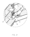
- FIG. 1 is a isometric diagram of an embodiment of a robot of the present disclosure.
- FIG. 2 is an enlarged view of circled portion II of FIG. 1 .
- FIG. 3 is a block diagram of an embodiment of a robot control system of the present disclosure.
- FIG. 4 is a block diagram of the function modules of the robot control system of the present disclosure.
- FIG. 5 is a flow chart of an embodiment of a robot control method.
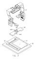
- FIG. 6 is a isometric diagram of a positioning mold of the present disclosure.
- FIG. 7 is an exploded, isometric view of the positioning mold of FIG. 6 .
- FIG. 8 is a isometric diagram of an embodiment of a guiding tool and a fastening tool used in the robot control system of the present disclosure.
- FIG. 9 is an exploded, isometric view of the components shown in FIG. 8 .
- Coupled is defined as connected, whether directly or indirectly through intervening components, and is not necessarily limited to physical connections.
- the connection can be such that the objects are permanently connected or releasably connected.
- comprising means “including, but not necessarily limited to”; it specifically indicates open-ended inclusion or portionship in a so-described combination, group, series, and the like.
- FIGS. 1 and 2 illustrate an embodiment of a robot 20 of the present disclosure which can grasp a target object.
- the robot 20 in accordance with an exemplary embodiment comprises a robotic arm 24 , the robotic arm 24 of the robot 20 is configured for grasping.
- the robot 20 controls the robotic arm 24 to execute operations.
- the robot 20 can comprise two robotic arms 24 .
- the robot 20 can transport the target object 40 to a platform 30 or can grasp and lift the target object 40 from the platform 30 .
- FIG. 3 illustrates a control system 10 installed in the robot 20 .
- the robot 20 further comprises an input/output unit 21 , a storage device 22 , and a controller 23 .
- the input/output unit 21 is configured to receive user commands, and show information to the user.
- the storage device 22 is configured to store program code and data of the robot control system 10 .
- the controller 23 controls the robot 20 .
- the input/output unit 21 can be a touch screen with input and output functions.
- the storage device 22 can be a secure digital card or a flash memory card.
- the controller 23 can be a central processing unit (CPU) or a digital signal processor (DSP).
- a coordinate system is created based on the platform 30 which supports the target objects 40 .
- the coordinate system includes X, Y, and Z axes. A plane including the X and Y axis is parallel with a panel including the platform 30 .
- a reminder message is generated.
- a guiding tool 71 (shown in FIG. 8 ) is placed on the platform 30 where the target objects 40 are located, and a fastening tool 72 (shown in FIG. 8 ) used with the guiding tool 71 is arranged on robotic arm 24 of the robot 20 , in response to the reminder message.
- a location of the fastening tool 72 relative to the guiding tool 71 is adjusted according to a predefined rule. When the location of the fastening tool 72 relative to the guiding tool 71 is corrected, a position of the robotic arm 24 of the robot 20 is determined according to the location of the fastening tool 72 .
- FIG. 4 illustrates a function modules diagram in accordance with an exemplary embodiment.
- the robot control system 10 comprises a building module 11 , an interaction module 12 , an adjusting module 13 , a judging module 14 , and a receiving module 15 .
- the modules mentioned in the present disclosure refer to a specific program command segments which can be executed by the controller 23 of the robot 20 .
- FIG. 5 shows a flowchart presented in accordance with the illustrated embodiment.
- the example method is provided by way of example, as there are a variety of ways to carry out the method. The method described below can be carried out using the configurations illustrated in FIG. 1 , for example, and various elements of these figures are referenced in explaining the example method.
- Blocks shown in FIG. 5 represent one or more processes, methods, or subroutines, carried out in the test method. Furthermore, the illustrated order of blocks is by example only and the order of the blocks can change. Additional blocks may be added or fewer blocks may be utilized without departing from this disclosure.
- the robot control method can begin at block 51 .
- a coordinate system is created based on supportive platform 30 bearing target objects 40 .
- the coordinate system includes X, Y, and Z axes.
- a plane including the X and Y axis is parallel with a panel including the platform 30 .
- the coordinate system is created based on the location of a positioning mold 60 (shown in FIG. 6 ) of the platform 30 .
- FIGS. 6 and 7 illustrate the positioning mold 60 .
- the positioning mold 60 comprises a fastening portion 61 and a moving portion 62 .
- the fastening portion 61 is fixed to the platform 30 through a plurality of screws.
- An L-shaped rail 611 is defined on the fastening portion 61 .
- the moving portion 62 is installed on the robotic arm 24 .
- a level sensor 621 (based on sensing gravity) and a height sensor 622 are defined on the moving portion 62 .
- the robotic arm 24 of the robot 20 drives the level sensor 621 to slide in the L-shaped rail 611 of the fastening portion 61 .
- the level sensor 621 and the height sensor 622 each carry a probe 623 .
- the probe 623 obtains data from two edges of the L-shaped rail 611 .
- the building module 11 creates a plane including the X and Y axes according to the data obtained by the probe 623 of the level sensor 621 .
- the building module 11 creates the Z axis of the coordinate system according to the data obtained by the probe 623 of the height sensor 622 .
- the interaction module 12 generates a reminder message after the coordinate system is created by the building module 11 , and displays such message through the input/output unit 21 .
- the interaction module 12 receives a feedback from the input/output unit 21 .
- FIGS. 8 and 9 illustrate a fastening tool 72 used with the guiding tool 71 .
- the guiding tool 71 is fixed in a position on the platform 30 through screws or locating studs (not shown in figures).
- the guiding tool 71 comprises a panel 712 and a convex block 713 placed in or on the panel 712 . At least one locating hole 711 is defined in the convex block 713 .
- the size and shape of the guiding tool 71 is equal to the size and shape of the target object 40 .
- Two level sensors 721 and a height sensor 722 are defined in the fastening tool 72 .
- Two level sensors 721 are symmetrically placed about the two sides of the height sensor 722 .
- Both the level sensors 721 and the height sensor 722 carry probes 723 .
- each level sensor 721 carries three probes 723 , and the three probes 723 are placed on the circumference of one circle.
- Each probe 723 communicates with a signal control unit 25 of the robot 20 .
- the signal control unit 25 connected to the probe 723 controls the input/output unit 21 to display a first signal, such as 1.
- the signal control unit 25 connected to the probe 723 controls the input/output unit 21 to display a second signal, such as 0.
- a diameter of the locating hole 711 can be a first preset value, such as 6.2 cms.
- Diameter of a circle marked by the three probes 723 of the level sensor 721 can be a second preset value, such as 6.0 cms. The first preset value is larger than the second preset value.
- the adjusting module 13 adjusts the location of the fastening tool 72 relative to the guiding tool 71 .
- the adjusting module 13 adjusts the location of the fastening tool 72 relative to the guiding tool 71 according to the signals outputted by the signal control unit 25 which is connected to the probe 23 .
- the adjusting module 13 adjusts the location of the fastening tool 72 relative to the guiding tool 71 according to the predefined rule, to achieve the second signal in place of the first signal outputted by the signal control unit 25 .
- the predefined rule can be to move one distance along the X, Y, or Z axes, or to rotate one distance along the Z axis. Each distance can be predefined and can change the location of the fastening tool 72 relative to the guiding tool 71 by a predefined value, such as 0.05 cm.
- the adjusting module 13 adjusts the location of the fastening tool 72 relative to the guiding tool 71 on the X or Y axes, in order that the signal control unit 25 outputs the second signal.
- the adjusting module 13 rotates the fastening tool 72 along the Z axis to adjust the location of the fastening tool 72 relative to the guiding tool 71 , until the signal control unit 25 outputs the second signal.
- the adjusting module 13 adjusts the location of the fastening tool 72 relative to the guiding tool 71 on the Z axis, the signal control unit 25 outputting the first signal.
- the judging module 14 determines whether the location of the fastening tool 72 relative to the guiding tool 71 is correctly adjusted. If the location of the fastening tool 72 relative to the guiding tool 71 is correct, block 55 is implemented, otherwise the process returns to block 53 .
- the judging module 14 determines that the location of the fastening tool 72 relative to the guiding tool 71 is correctly adjusted, and the robotic arm 24 of the robot 20 can grasp the target objects 40 precisely and accurately.
- the receiving module 15 obtains the coordinates of the robotic arm 24 of the robot 20 when the location of the fastening tool 72 relative to the guiding tool 71 is correctly adjusted, and stores the coordinates of the robotic arm 24 of the robot 20 .
Landscapes
- Engineering & Computer Science (AREA)
- Robotics (AREA)
- Mechanical Engineering (AREA)
- Physics & Mathematics (AREA)
- General Physics & Mathematics (AREA)
- Automation & Control Theory (AREA)
- Manipulator (AREA)
Abstract
Description
Claims (10)
Applications Claiming Priority (3)
| Application Number | Priority Date | Filing Date | Title |
|---|---|---|---|
| CN201610007741.1 | 2016-01-07 | ||
| CN201610007741.1A CN106945034B (en) | 2016-01-07 | 2016-01-07 | Robot point location adjusting method and system |
| CN201610007741 | 2016-01-07 |
Publications (2)
| Publication Number | Publication Date |
|---|---|
| US20170197309A1 US20170197309A1 (en) | 2017-07-13 |
| US10022869B2 true US10022869B2 (en) | 2018-07-17 |
Family
ID=59274680
Family Applications (1)
| Application Number | Title | Priority Date | Filing Date |
|---|---|---|---|
| US15/140,484 Active 2036-07-16 US10022869B2 (en) | 2016-01-07 | 2016-04-28 | Robot control system and method |
Country Status (4)
| Country | Link |
|---|---|
| US (1) | US10022869B2 (en) |
| JP (1) | JP6643171B2 (en) |
| CN (1) | CN106945034B (en) |
| TW (1) | TWI661914B (en) |
Families Citing this family (3)
| Publication number | Priority date | Publication date | Assignee | Title |
|---|---|---|---|---|
| CN109956240B (en) * | 2017-12-26 | 2021-11-30 | 河南森源重工有限公司 | Method and tool for positioning lifting lug and sliding chute of sanitation vehicle |
| TWI672202B (en) * | 2018-12-05 | 2019-09-21 | 國立虎尾科技大學 | Robotic arm guiding and positioning device |
| CN113927584B (en) * | 2021-10-19 | 2023-04-21 | 深圳市优必选科技股份有限公司 | Robot control method and device, computer readable storage medium and robot |
Citations (27)
| Publication number | Priority date | Publication date | Assignee | Title |
|---|---|---|---|---|
| US20020188379A1 (en) * | 2001-06-07 | 2002-12-12 | Mcgee H. Dean | Robot calibration system and method of determining a position of a robot relative to an electrically-charged calibration object |
| US20030110649A1 (en) * | 2001-12-19 | 2003-06-19 | Applied Materials, Inc. | Automatic calibration method for substrate carrier handling robot and jig for performing the method |
| US20050171728A1 (en) * | 2001-03-10 | 2005-08-04 | Rudolf Rogele | Coordinate measuring apparatus |
| US20070138374A1 (en) * | 2005-10-17 | 2007-06-21 | Shin Nippon Koki Co., Ltd. | Parallel kinematic machine, calibration method of parallel kinematic machine, and calibration program product |
| US20070150100A1 (en) * | 2005-11-18 | 2007-06-28 | Strasbaugh | Robot calibration system and method |
| US20080188986A1 (en) * | 2004-10-25 | 2008-08-07 | University Of Dayton | Method and System to Provide Improved Accuracies in Multi-Jointed Robots Through Kinematic Robot Model Parameters Determination |
| US20090096148A1 (en) * | 2007-10-10 | 2009-04-16 | Denso Corporation | Workpiece grasper and workpiece transfer apparatus using the same |
| US20090235547A1 (en) * | 2006-06-06 | 2009-09-24 | Renishaw Plc | Method for Measuring an Object |
| US20100161125A1 (en) * | 2008-12-24 | 2010-06-24 | Canon Kabushiki Kaisha | Work apparatus and calibration method for the same |
| US20100210971A1 (en) * | 2009-02-19 | 2010-08-19 | Ali Shabram | Method and system for real time characterization of soft materials and biological tissues based on nonlinear properties |
| US20110015774A1 (en) * | 2008-03-17 | 2011-01-20 | Tokyo Electron Limited | Control device and control method |
| US20110033254A1 (en) * | 2009-08-06 | 2011-02-10 | Kmt Robotic Solutions, Inc. | System And Method Of Locating Relative Positions Of Objects |
| US20110046782A1 (en) * | 2008-04-30 | 2011-02-24 | Abb Technology Ab | A method and system for determining the relation between a robot coordinate system and a local coordinate system located in the working range of the robot |
| US20110270443A1 (en) * | 2010-04-28 | 2011-11-03 | Kabushiki Kaisha Yaskawa Denki | Apparatus and method for detecting contact position of robot |
| US20120002216A1 (en) * | 2009-03-17 | 2012-01-05 | Kawasaki Jukogyo Kabushiki Kaisha | Robot and auto-zeroing method |
| US20120072005A1 (en) * | 2006-10-27 | 2012-03-22 | Tokyo Electron Limited | Substrate processing system, substrate placing position adjusting method and storage medium |
| US20120078418A1 (en) * | 2009-06-08 | 2012-03-29 | Jin Hwan Borm | Robot calibration apparatus and method for same |
| US20120116586A1 (en) * | 2009-06-30 | 2012-05-10 | Ulvac, Inc. | Teaching apparatus of robot and teaching method of robot |
| US20130178980A1 (en) * | 2009-12-18 | 2013-07-11 | Jerome Chemouny | Anti-collision system for moving an object around a congested environment |
| US20140116847A1 (en) * | 2012-10-31 | 2014-05-01 | Senju Metal lndustry Co., Ltd. | Positioning Jig and Method of Adjusting Position |
| US20140156072A1 (en) * | 2009-08-03 | 2014-06-05 | Fanuc Ltd | Apparatus and method for measuring tool center point position of robot |
| US20150045953A1 (en) * | 2013-08-09 | 2015-02-12 | Kabushiki Kaisha Yaskawa Denki | Robot system, robot control apparatus, method for controlling robot |
| US20160096205A1 (en) * | 2013-06-18 | 2016-04-07 | SCREEN Holdings Co., Ltd. | Substrate holding and rotating device, substrate processing device equipped with same, and substrate processing method |
| US20160184986A1 (en) * | 2012-02-08 | 2016-06-30 | Vanrx Pharmaceuticals, Inc. | Articulated arm apparatus and system |
| US20170151666A1 (en) * | 2015-11-26 | 2017-06-01 | Seiko Epson Corporation | Robot and robot system |
| US20170326739A1 (en) * | 2014-12-09 | 2017-11-16 | Canon Kabushiki Kaisha | Information processing apparatus, information processing method, and program |
| US20170341229A1 (en) * | 2016-05-24 | 2017-11-30 | Semes Co., Ltd. | Stocker for receiving cassettes and method of teaching a stocker robot disposed therein |
Family Cites Families (16)
| Publication number | Priority date | Publication date | Assignee | Title |
|---|---|---|---|---|
| JPS60167005A (en) * | 1984-02-10 | 1985-08-30 | Oki Electric Ind Co Ltd | Teaching method of industrial robot |
| JPH02183102A (en) * | 1989-01-10 | 1990-07-17 | Fanuc Ltd | Automatic calibration adjusting system for visual sensor |
| JP2786225B2 (en) * | 1989-02-01 | 1998-08-13 | 株式会社日立製作所 | Industrial robot control method and apparatus |
| FR2643450B1 (en) * | 1989-02-21 | 1994-03-18 | Aerospatiale Ste Nationale Indle | SYSTEM FOR MATERIALIZING A POINT IN SPACE, ITS APPLICATIONS AND TOOLS FOR SAID SYSTEM |
| JPH09106311A (en) * | 1995-10-09 | 1997-04-22 | Nissan Motor Co Ltd | Automatic correction device for teaching data |
| JP3304251B2 (en) * | 1995-11-27 | 2002-07-22 | 松下電工株式会社 | Automatic teaching method and device for assembly robot |
| JP4305652B2 (en) * | 2001-09-07 | 2009-07-29 | 株式会社安川電機 | Wafer position teaching method |
| JP5663847B2 (en) * | 2009-06-11 | 2015-02-04 | 株式会社Ihi | Calibration jig and calibration method |
| CN102166747A (en) * | 2010-02-26 | 2011-08-31 | 鸿富锦精密工业(深圳)有限公司 | System for testing object by mechanical arm and method thereof |
| CN102601800A (en) * | 2011-01-19 | 2012-07-25 | 鸿富锦精密工业(深圳)有限公司 | Manipulator positioning device and manipulator with same |
| JP5447432B2 (en) * | 2011-05-09 | 2014-03-19 | 株式会社安川電機 | Robot teaching system and teaching method |
| CN102785252A (en) * | 2011-05-19 | 2012-11-21 | 鸿富锦精密工业(深圳)有限公司 | Mechanical arm and detecting device |
| AT513697B1 (en) * | 2012-11-08 | 2014-09-15 | Stiwa Holding Gmbh | Method and machine system for positioning two movable units in a relative position to each other |
| JP6234091B2 (en) * | 2013-07-11 | 2017-11-22 | キヤノン株式会社 | Robot apparatus and teaching point setting method |
| CN103538072A (en) * | 2013-10-22 | 2014-01-29 | 昆山中士设备工业有限公司 | Manipulator with accurate positioning ability |
| JP2015100863A (en) * | 2013-11-22 | 2015-06-04 | キヤノン株式会社 | Teaching method for robot |
-
2016
- 2016-01-07 CN CN201610007741.1A patent/CN106945034B/en active Active
- 2016-01-22 TW TW105102071A patent/TWI661914B/en active
- 2016-04-15 JP JP2016081834A patent/JP6643171B2/en active Active
- 2016-04-28 US US15/140,484 patent/US10022869B2/en active Active
Patent Citations (27)
| Publication number | Priority date | Publication date | Assignee | Title |
|---|---|---|---|---|
| US20050171728A1 (en) * | 2001-03-10 | 2005-08-04 | Rudolf Rogele | Coordinate measuring apparatus |
| US20020188379A1 (en) * | 2001-06-07 | 2002-12-12 | Mcgee H. Dean | Robot calibration system and method of determining a position of a robot relative to an electrically-charged calibration object |
| US20030110649A1 (en) * | 2001-12-19 | 2003-06-19 | Applied Materials, Inc. | Automatic calibration method for substrate carrier handling robot and jig for performing the method |
| US20080188986A1 (en) * | 2004-10-25 | 2008-08-07 | University Of Dayton | Method and System to Provide Improved Accuracies in Multi-Jointed Robots Through Kinematic Robot Model Parameters Determination |
| US20070138374A1 (en) * | 2005-10-17 | 2007-06-21 | Shin Nippon Koki Co., Ltd. | Parallel kinematic machine, calibration method of parallel kinematic machine, and calibration program product |
| US20070150100A1 (en) * | 2005-11-18 | 2007-06-28 | Strasbaugh | Robot calibration system and method |
| US20090235547A1 (en) * | 2006-06-06 | 2009-09-24 | Renishaw Plc | Method for Measuring an Object |
| US20120072005A1 (en) * | 2006-10-27 | 2012-03-22 | Tokyo Electron Limited | Substrate processing system, substrate placing position adjusting method and storage medium |
| US20090096148A1 (en) * | 2007-10-10 | 2009-04-16 | Denso Corporation | Workpiece grasper and workpiece transfer apparatus using the same |
| US20110015774A1 (en) * | 2008-03-17 | 2011-01-20 | Tokyo Electron Limited | Control device and control method |
| US20110046782A1 (en) * | 2008-04-30 | 2011-02-24 | Abb Technology Ab | A method and system for determining the relation between a robot coordinate system and a local coordinate system located in the working range of the robot |
| US20100161125A1 (en) * | 2008-12-24 | 2010-06-24 | Canon Kabushiki Kaisha | Work apparatus and calibration method for the same |
| US20100210971A1 (en) * | 2009-02-19 | 2010-08-19 | Ali Shabram | Method and system for real time characterization of soft materials and biological tissues based on nonlinear properties |
| US20120002216A1 (en) * | 2009-03-17 | 2012-01-05 | Kawasaki Jukogyo Kabushiki Kaisha | Robot and auto-zeroing method |
| US20120078418A1 (en) * | 2009-06-08 | 2012-03-29 | Jin Hwan Borm | Robot calibration apparatus and method for same |
| US20120116586A1 (en) * | 2009-06-30 | 2012-05-10 | Ulvac, Inc. | Teaching apparatus of robot and teaching method of robot |
| US20140156072A1 (en) * | 2009-08-03 | 2014-06-05 | Fanuc Ltd | Apparatus and method for measuring tool center point position of robot |
| US20110033254A1 (en) * | 2009-08-06 | 2011-02-10 | Kmt Robotic Solutions, Inc. | System And Method Of Locating Relative Positions Of Objects |
| US20130178980A1 (en) * | 2009-12-18 | 2013-07-11 | Jerome Chemouny | Anti-collision system for moving an object around a congested environment |
| US20110270443A1 (en) * | 2010-04-28 | 2011-11-03 | Kabushiki Kaisha Yaskawa Denki | Apparatus and method for detecting contact position of robot |
| US20160184986A1 (en) * | 2012-02-08 | 2016-06-30 | Vanrx Pharmaceuticals, Inc. | Articulated arm apparatus and system |
| US20140116847A1 (en) * | 2012-10-31 | 2014-05-01 | Senju Metal lndustry Co., Ltd. | Positioning Jig and Method of Adjusting Position |
| US20160096205A1 (en) * | 2013-06-18 | 2016-04-07 | SCREEN Holdings Co., Ltd. | Substrate holding and rotating device, substrate processing device equipped with same, and substrate processing method |
| US20150045953A1 (en) * | 2013-08-09 | 2015-02-12 | Kabushiki Kaisha Yaskawa Denki | Robot system, robot control apparatus, method for controlling robot |
| US20170326739A1 (en) * | 2014-12-09 | 2017-11-16 | Canon Kabushiki Kaisha | Information processing apparatus, information processing method, and program |
| US20170151666A1 (en) * | 2015-11-26 | 2017-06-01 | Seiko Epson Corporation | Robot and robot system |
| US20170341229A1 (en) * | 2016-05-24 | 2017-11-30 | Semes Co., Ltd. | Stocker for receiving cassettes and method of teaching a stocker robot disposed therein |
Also Published As
| Publication number | Publication date |
|---|---|
| TWI661914B (en) | 2019-06-11 |
| US20170197309A1 (en) | 2017-07-13 |
| JP2017121691A (en) | 2017-07-13 |
| CN106945034B (en) | 2021-09-03 |
| CN106945034A (en) | 2017-07-14 |
| JP6643171B2 (en) | 2020-02-12 |
| TW201729959A (en) | 2017-09-01 |
Similar Documents
| Publication | Publication Date | Title |
|---|---|---|
| US9199379B2 (en) | Robot system display device | |
| CN101927494B (en) | Shape detection system | |
| CN109910000B (en) | Calibration and operation of vision-based steering systems | |
| US8498745B2 (en) | Robot apparatus and gripping method for use in robot apparatus | |
| US20180126557A1 (en) | Method for industrial robot commissioning, industrial robot system and control system using the same | |
| US9519736B2 (en) | Data generation device for vision sensor and detection simulation system | |
| US10022869B2 (en) | Robot control system and method | |
| US10331728B2 (en) | System and method of robot calibration using image data | |
| EP2271465A1 (en) | Robot parts assembly on a workpiece moving on an assembly line | |
| KR102658278B1 (en) | Mobile robot and method of aligning robot arm thereof | |
| US11584013B2 (en) | System, device and method for determining error in robotic manipulator-to-camera calibration | |
| CN107263469B (en) | Mechanical arm attitude compensation method and device, storage medium and mechanical arm | |
| CN109708607A (en) | Detection device, detection method and storage equipment | |
| JP2013166240A (en) | Apparatus and method for controlling multi-axis stage device | |
| JP2006234737A (en) | Apparatus for measuring three-dimensional coordinate having posture of probe compensation function | |
| CN115122333A (en) | Robot calibration method and device, electronic equipment and storage medium | |
| US20210201011A1 (en) | Data processing method for multi-sensor fusion, positioning apparatus and virtual reality device | |
| JP6619106B2 (en) | Method for calibrating a touch screen panel using an industrial robot, system using the same, industrial robot, and touch screen | |
| JP4595042B2 (en) | Three-dimensional measurement method and system, and manipulator control method and apparatus | |
| US20200384650A1 (en) | Calibration detecting apparatus, method, and program | |
| US9858364B2 (en) | Computing device and method for processing point clouds | |
| CN115990890B (en) | Calibration method and device for manipulator, computer equipment and storage medium | |
| US8504207B2 (en) | Electronic device and method for controlling motions of mechanical arm using the electronic device | |
| US20230090193A1 (en) | Off-line simulation system | |
| WO2016189740A1 (en) | Robot system, teaching jig and teaching method |
Legal Events
| Date | Code | Title | Description |
|---|---|---|---|
| AS | Assignment |
Owner name: HON HAI PRECISION INDUSTRY CO., LTD., TAIWAN Free format text: ASSIGNMENT OF ASSIGNORS INTEREST;ASSIGNORS:LIU, YU-CHING;CHANG, HSI-CHE;LIN, YU-NAN;AND OTHERS;SIGNING DATES FROM 20160328 TO 20160425;REEL/FRAME:038399/0047 Owner name: HONGFUJIN PRECISION ELECTRONICS (ZHENGZHOU) CO.,LT Free format text: ASSIGNMENT OF ASSIGNORS INTEREST;ASSIGNORS:LIU, YU-CHING;CHANG, HSI-CHE;LIN, YU-NAN;AND OTHERS;SIGNING DATES FROM 20160328 TO 20160425;REEL/FRAME:038399/0047 |
|
| STCF | Information on status: patent grant |
Free format text: PATENTED CASE |
|
| MAFP | Maintenance fee payment |
Free format text: PAYMENT OF MAINTENANCE FEE, 4TH YEAR, LARGE ENTITY (ORIGINAL EVENT CODE: M1551); ENTITY STATUS OF PATENT OWNER: LARGE ENTITY Year of fee payment: 4 |