US10019264B2 - System and method for contextual vectorization of instructions at runtime - Google Patents
System and method for contextual vectorization of instructions at runtime Download PDFInfo
- Publication number
- US10019264B2 US10019264B2 US15/052,765 US201615052765A US10019264B2 US 10019264 B2 US10019264 B2 US 10019264B2 US 201615052765 A US201615052765 A US 201615052765A US 10019264 B2 US10019264 B2 US 10019264B2
- Authority
- US
- United States
- Prior art keywords
- instructions
- sequence
- processor
- instruction
- sub
- Prior art date
- Legal status (The legal status is an assumption and is not a legal conclusion. Google has not performed a legal analysis and makes no representation as to the accuracy of the status listed.)
- Active, expires
Links
- 238000000034 method Methods 0.000 title claims abstract description 16
- 230000015654 memory Effects 0.000 claims description 27
- 238000011156 evaluation Methods 0.000 claims description 16
- 230000003139 buffering effect Effects 0.000 claims 2
- 238000010586 diagram Methods 0.000 description 8
- 101100285899 Saccharomyces cerevisiae (strain ATCC 204508 / S288c) SSE2 gene Proteins 0.000 description 4
- 230000006870 function Effects 0.000 description 4
- 230000001343 mnemonic effect Effects 0.000 description 4
- 238000012545 processing Methods 0.000 description 4
- 230000003068 static effect Effects 0.000 description 4
- 239000000203 mixture Substances 0.000 description 2
- 238000004590 computer program Methods 0.000 description 1
- 230000003278 mimic effect Effects 0.000 description 1
- 238000005457 optimization Methods 0.000 description 1
- 230000004044 response Effects 0.000 description 1
- 238000012360 testing method Methods 0.000 description 1
- 238000012549 training Methods 0.000 description 1
Images


Classifications
-
- G—PHYSICS
- G06—COMPUTING; CALCULATING OR COUNTING
- G06F—ELECTRIC DIGITAL DATA PROCESSING
- G06F9/00—Arrangements for program control, e.g. control units
- G06F9/06—Arrangements for program control, e.g. control units using stored programs, i.e. using an internal store of processing equipment to receive or retain programs
- G06F9/30—Arrangements for executing machine instructions, e.g. instruction decode
- G06F9/32—Address formation of the next instruction, e.g. by incrementing the instruction counter
- G06F9/322—Address formation of the next instruction, e.g. by incrementing the instruction counter for non-sequential address
- G06F9/325—Address formation of the next instruction, e.g. by incrementing the instruction counter for non-sequential address for loops, e.g. loop detection or loop counter
-
- G—PHYSICS
- G06—COMPUTING; CALCULATING OR COUNTING
- G06F—ELECTRIC DIGITAL DATA PROCESSING
- G06F9/00—Arrangements for program control, e.g. control units
- G06F9/06—Arrangements for program control, e.g. control units using stored programs, i.e. using an internal store of processing equipment to receive or retain programs
- G06F9/30—Arrangements for executing machine instructions, e.g. instruction decode
- G06F9/30145—Instruction analysis, e.g. decoding, instruction word fields
- G06F9/3016—Decoding the operand specifier, e.g. specifier format
-
- G—PHYSICS
- G06—COMPUTING; CALCULATING OR COUNTING
- G06F—ELECTRIC DIGITAL DATA PROCESSING
- G06F9/00—Arrangements for program control, e.g. control units
- G06F9/06—Arrangements for program control, e.g. control units using stored programs, i.e. using an internal store of processing equipment to receive or retain programs
- G06F9/30—Arrangements for executing machine instructions, e.g. instruction decode
- G06F9/30098—Register arrangements
- G06F9/30105—Register structure
-
- G—PHYSICS
- G06—COMPUTING; CALCULATING OR COUNTING
- G06F—ELECTRIC DIGITAL DATA PROCESSING
- G06F9/00—Arrangements for program control, e.g. control units
- G06F9/06—Arrangements for program control, e.g. control units using stored programs, i.e. using an internal store of processing equipment to receive or retain programs
- G06F9/30—Arrangements for executing machine instructions, e.g. instruction decode
- G06F9/3017—Runtime instruction translation, e.g. macros
-
- G—PHYSICS
- G06—COMPUTING; CALCULATING OR COUNTING
- G06F—ELECTRIC DIGITAL DATA PROCESSING
- G06F9/00—Arrangements for program control, e.g. control units
- G06F9/06—Arrangements for program control, e.g. control units using stored programs, i.e. using an internal store of processing equipment to receive or retain programs
- G06F9/30—Arrangements for executing machine instructions, e.g. instruction decode
- G06F9/30181—Instruction operation extension or modification
-
- G—PHYSICS
- G06—COMPUTING; CALCULATING OR COUNTING
- G06F—ELECTRIC DIGITAL DATA PROCESSING
- G06F9/00—Arrangements for program control, e.g. control units
- G06F9/06—Arrangements for program control, e.g. control units using stored programs, i.e. using an internal store of processing equipment to receive or retain programs
- G06F9/30—Arrangements for executing machine instructions, e.g. instruction decode
- G06F9/38—Concurrent instruction execution, e.g. pipeline or look ahead
- G06F9/3802—Instruction prefetching
-
- G—PHYSICS
- G06—COMPUTING; CALCULATING OR COUNTING
- G06F—ELECTRIC DIGITAL DATA PROCESSING
- G06F9/00—Arrangements for program control, e.g. control units
- G06F9/06—Arrangements for program control, e.g. control units using stored programs, i.e. using an internal store of processing equipment to receive or retain programs
- G06F9/30—Arrangements for executing machine instructions, e.g. instruction decode
- G06F9/38—Concurrent instruction execution, e.g. pipeline or look ahead
- G06F9/3836—Instruction issuing, e.g. dynamic instruction scheduling or out of order instruction execution
Definitions
- Embodiments described herein generally relate to processors.
- embodiments described generally relate to processors configured to contextually optimize instructions at runtime.
- Parallel processing is generally faster than scalar execution of one data point at a time.
- SIMD Single Instruction Multiple Data
- SIMD processors can take advantage of parallelism in performing mathematical operations and in moving data. SIMD processors can load or store multiple data items simultaneously, resulting in a performance gain compared to the slower, scalar processors that load or store one datum at a time. When executing computer programs on a processor with parallel resources, utilizing SIMD instructions offers better performance than utilizing scalar instructions.
- SIMD Instruction Set Architecture Programming using a SIMD Instruction Set Architecture (ISA), however, can be challenging.
- SIMD ISA's for example, are generally processor-specific. Programs that use SIMD instructions may need to be rewritten and customized to suit a new processor generation.
- the work required to adapt scalar instructions to a new instruction set architecture, including rewriting the code, documenting the code; enabling compilers to emit the code, training users to use the code, and to debug and collect traces of code execution may need to be partly or wholly repeated for reuse with each new generation of instruction set architecture (e.g. MMX, SSE, SSE2, SSE3, SSE4, AVX, AVX2, AVX 3.1, and AVX 3.2).
- What is needed, therefore, is a way to allow programmers to take advantage of SIMD Instruction Set Architectures while avoiding the challenges inherent in conventional solutions.
- FIG. 1 is a block flow diagram illustrating a procedure for a processor to contextually optimize instructions at runtime according to one embodiment.
- FIG. 2 is a block diagram illustrating processing components used by a processor to contextually optimize instructions at runtime according to one embodiment.
- FIG. 3 illustrates an instruction and its various fields according to one embodiment.
- FIG. 4 illustrates an exemplary register allotment by a processor optimizing Vectorbeam code of Table 2 according to an embodiment.
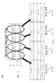
- FIG. 5 illustrates an exemplary allotment of multiple computational resources used to process the allotted registers of FIG. 4 in parallel according to one embodiment.
- FIG. 6 illustrates a portion of a lookup table listing vector instruction substitutes for scalar instructions according to one embodiment.
- FIG. 7 illustrates a vector processor register file according to one embodiment.
- references in the specification to “one embodiment,” “an embodiment,” “an example embodiment,” etc., indicate that the embodiment described may include a particular feature, structure, or characteristic, but every embodiment need not necessarily include the particular feature, structure, or characteristic. Moreover, such phrases are not necessarily referring to the same embodiment. Further, when a particular feature, structure, or characteristic is described in connection with an embodiment, it is submitted that it is within the knowledge of one skilled in the art to affect such feature, structure, or characteristic in connection with other embodiments whether or not explicitly described.
- the instruction set is the part of the computer architecture related to programming, and generally includes the native data types, instructions, register architecture, addressing modes, memory architecture, interrupt and exception handling, and external input and output (I/O).
- I/O external input and output
- the term instruction herein may refer to a macro-instruction, e.g., an instruction that is provided to the processor for execution.
- a processor e.g., having one or more cores to decode and/or execute instructions
- a processor contextually optimizes instructions at runtime. Specifically, the processor optimizes a sequence of sub-optimal instructions dynamically at runtime.
- Sub-optimal instructions refer to instructions that make less-than-full use of the available resources of a processor, or which can be optimized to take advantage of a processor's instruction set architecture.
- sequences of sub-optimal instructions are stored in instruction storage, and are surrounded by start- and end-delimiting instructions.
- the sequence of sub-optimal code surrounded by start-of-sequence and end-of-sequence instructions is referred to herein as Vectorbeam code.
- the claims herein are not limited by the name Vectorbeam. In alternate embodiments, the code can be referenced by different names.
- the Vectorbeam instructions are not limited in their choice of particular opcodes or mnemonics.
- a processor is configured to detect a Vectorbeam code sequence of sub-optimal instructions, to buffer the sequence, and to access a lookup table to identify one or more instructions to substitute for and optimize one or more of the sub-optimal instructions of the Vectorbeam code sequence.
- the start-of-sequence instruction and end-of-sequence instruction can be chosen to provide the processor with a hint on how to optimize the code sequence.
- a processor can surmise that the sequence of sub-optimal instructions is meant to be an iterative loop because the sequence of sub-optimal instructions is preceded by a start-of-sequence delimiting instruction, “foreach,” and is followed by an end-of-sequence delimiting instruction, “next.”
- the start-of-sequence instruction may hint that the sequence of sub-optimal instructions is iterative by using delimiting instructions “foreach,” or “do until,” or “repeat until,” or “do while.”
- the end-of-sequence instruction may be similarly named so as to suggest its function.
- start-of-sequence and end-of-sequence instructions may also have predetermined values that are not human readable, or are numeric, or have been selected automatically or randomly without human involvement.
- a sequence of sub-optimal instructions refers to computer instructions that take less-than-full advantage of the parallel resources available in a processor on which those instructions are meant to be executed.
- sequence of sub-optimal instructions may be an iterative, scalar loop, which, as written, uses fewer parallel resources than are available in the processor.
- sequence of sub-optimal instructions may have been written to use 64-bit registers, but the processor on which those instructions are to be executed has 128-bit registers available.
- sequence of sub-optimal instructions relate to multimedia operations, such as dimming the brightness of a screen of pixels.
- scalar mathematical operations can be replaced with wide vector instructions.
- the start-of-sequence instruction may include operands that provide metadata to a processor that will implement the Vectorbeam code sequence.
- the metadata gives the processor a hint as to how to optimize the code.
- the sequence of sub-optimal instructions is preceded by a start-of-sequence instruction, “for each rax, 0, 64, 1”
- the metadata, “rax, 0, 64, and 1,” provide the processor with a hint that the sub-optimal code should be looped using register rax as a loop index, varying rax 64 times, starting at 0, with a stride of 1 for each iteration.
- FIG. 1 is a block flow diagram illustrating a procedure for a processor to contextually optimize instructions at runtime according to one embodiment.
- a processor that is configured to execute a procedure to contextually optimize instructions at runtime according to block flow diagram 100 fetches an instruction at 102 , decodes the instruction at 104 , and tests whether it is in optimize mode at 106 .
- the instruction to be fetched is stored in an instruction buffer.
- the instruction may be stored in an instruction register, a general register, a program stack, or a memory, including static and dynamic random access memories.
- a processor performing the procedure of flow diagram 100 decodes the fetched instruction (e.g., macro-instruction) at 104 to generate as an output one or more micro-operations, micro-code entry points, micro-instructions, other instructions, or other control signals.
- fetched instruction e.g., macro-instruction
- a Vectorbeam code sequence consisting of a sequence of sub-optimal instructions is stored in the memory, preceded by a start-of-sequence instruction and followed by an end-of-sequence instruction.
- the start-of-sequence instruction may be coded in human-readable assembly code, and have mnemonics defined in a way so as to suggest how the sub-optimal instructions should be optimized.
- the start-of-sequence instruction may be “for each,” or “do until,” or “repeat until,” or “do while,” to name a few examples.
- the end-of-sequence instruction may be similarly named so as to suggest its function. (e.g.
- start-of-sequence and end-of-sequence instructions may also have predetermined values that are not human readable, or are numeric, or have been selected automatically or randomly without human involvement.
- the Vectorbeam code's sub-optimal code sequences in one embodiment are written to mimic scalar mnemonics and appear to have a scalar and/or serial flow of execution, making them easy to understand and to debug. Delimiting the sub-optimal code sequences with easy-to-understand delimiters may enhance the readability of the code, and may also suggest to the processor how to optimize the code at runtime.
- the processor determines at 106 that it is not running in optimize mode, it dispatches the decoded instruction to be executed at 114 , and commits or retires the instruction at 116 .
- Entering the optimize mode in one embodiment occurs during run-time when the instruction decoded at 104 is a start-of-sequence instruction, as described above.
- the processor enters the optimize mode at power-on, or after reset.
- the processor enters optimize mode implicitly after fetching a particular sequence of instructions at 102 , decoding them at 104 , and detecting one or more sub-optimal instructions, such as scalar instructions, or instructions from an older instruction set architecture.
- the processor enters optimize mode implicitly during run-time in response to a predefined run-time event.
- Exiting the optimize mode in one embodiment occurs during run-time when the instruction decoded at 104 is an end-of-sequence instruction, as described above.
- the processor exits the optimize mode implicitly after occurrence of a condition, such as failing to identify a substitute instruction for a time.
- the processor remains in the optimize mode indefinitely.
- the processor determines at 106 that it is already in optimize mode, or if the processor detects a start-of-sequence instruction, it enqueues the decoded instruction at 107 into an instruction buffer.
- the instruction buffer in one embodiment is a series of general purpose registers. In other embodiments, the instruction buffer may utilize instruction registers, scalar registers, shift registers, a stack memory, a static or dynamic RAM memory, or a cache memory.
- the processor compares the instructions in the instruction buffer to a lookup table at 108 to determine whether suitable substitute instructions are available, including substitute instructions that would yield better performance.
- the processor in one embodiment is guided by the metadata included with the start-of-sequence delimiter.
- the processor in one embodiment is guided by the state and contents of the register file, described further below with respect to FIG. 7 .
- the sub-optimal instructions of the Vectorbeam code comprise scalar instructions
- the substitute instructions comprise vector instructions or SIMD instructions.
- the sub-optimal instructions of the Vectorbeam code include instructions from an older generation processor's instruction set architecture, and the substitute instructions are selected from the instruction set of a more recent processor.
- the sequence of sub-optimal instructions of the Vectorbeam code consists of an iterative loop of instructions, and the substitute instructions complete the operation with fewer loops, or with the use of vector instructions.
- the sequence of sub-optimal instructions in the instruction buffer consists of a conditional loop, and the substitute instructions complete the operation with fewer loops, or with the use of vector instructions. If the processor determines at 108 that a substitute instruction that would yield better performance is available, it selects one or more substitute instructions at 110 .
- the processor selects the decoded instruction for execution if no substitute instructions were available at 108 , or selects the one or more substitute instructions that were selected at 110 .
- the processor maintains a sequence of instructions in the instruction buffer, and considers multiple instructions when evaluating potential substitutes at 108 .
- the processor limits the number of instructions stored in the instruction buffer, and, if the number of instructions exceeds that limit, the processor removes one or more instructions from the instruction buffer and dispatches them to be executed at 114 .
- the processor executes the decoded instruction or the one or more substitute instructions. After execution, the processor retires or commits the instruction at 116 , ensuring that execution results are written to or have been written to their destinations, and freeing up or releasing resources for later use.
- FIG. 2 is a block diagram illustrating processing components used by a processor to contextually optimize Vectorbeam code instructions at runtime according to one embodiment.
- block diagram 200 includes instruction storage 202 , fetch circuit 204 , decode circuit 206 , execution circuit 220 , and retire/commit circuit 226 .
- Decode circuit 206 includes decode logic 208 , optimize mode detector 210 , instruction buffer 212 , lookup table 214 , substitute evaluation logic 216 , and instruction selector 218 .
- Block diagram 200 further includes execution circuit 220 , registers 222 , memory 224 , and retire/commit circuit 226 .
- instruction storage 202 is a register file.
- instruction storage 202 may be an instruction buffer, an instruction register, a general register, a program stack, or a static or dynamic random access memory.
- the processor passes the fetched instruction to decode circuit 206 , which decodes the fetched instruction with decode logic 208 .
- the instruction including its opcode and optional operands, is described below with reference to FIG. 3 .
- the processor detects whether it is in optimize mode with optimize mode detector 210 . If the processor is not in optimize mode, the processor dispatches the decoded instruction to execution circuit 220 .
- instruction buffer 212 has four entries, but the number of entries is variable: it could be fewer than four, it could be greater than four, or it could be adjusted dynamically, as would be understood by those of skill.
- the processor uses substitute evaluation logic 216 to evaluate the decoded instructions in instruction buffer 212 .
- substitute evaluation logic 216 accesses lookup table 214 during run-time to determine whether any substitute instructions are available.
- the lookup table in one embodiment compares mnemonics of sub-optimal Vectorbeam instructions in the instruction buffer to a listing of substitute instructions.
- the substitute instructions are vector instructions.
- the substitute instructions are SIMD instructions.
- the substitute instructions are from a newer instruction set architecture than the sub-optimal instructions.
- substitute evaluation logic 216 in one embodiment is guided by metadata provided with a start-of-sequence instructions.
- substitute evaluation logic 216 in one embodiment evaluates the run-time state of the processor registers. For example, if multiple registers are used in determining memory addresses, and if those memory addresses fall in the same cache line, substitute evaluation logic 216 substitutes a vector memory access for scalar memory accesses associated with those memory addresses.
- substitute evaluation logic 216 determines that a substitute instruction is available, the substitute instruction is passed to dispatch selector 218 to be dispatched for execution.
- the substitute instruction is written into instruction buffer 212 , adding to or replacing instructions therein.
- decode circuit 206 uses dispatch selector 218 to select instructions to dispatch either from instruction buffer 212 or from substitute evaluation logic 216 .
- Execution circuit 220 in one embodiment is a vector processor. In alternate embodiments, execution circuit 220 may include multiple cores, and parallel hardware. Execution circuit 220 in one embodiment utilizes registers 222 and memory 224 to store intermediate results and to otherwise support execution. After execution, retire/commit circuit 226 ensures that execution results are written to or have been written to their destinations, and frees up or releases resources for later use.
- FIG. 3 illustrates an instruction and its various fields according to an embodiment.
- instruction 300 includes opcode 302 and optional first, second, and third operand identifiers, 304 , 306 , and 308 , respectively.
- Opcode 302 identifies the instruction and/or the operation to be performed, as well as the type of operands (e.g., “start-of-sequence” or “end-of-sequence”).
- First, second, and third operand identifiers, 304 , 306 , and 308 are optional.
- opcode 302 is a “start-of-sequence” instruction and first, second, and third operand identifiers 304 , 306 , and 308 represent metadata that describe the sub-optimal instructions that follow, providing a hint or a suggestion to the processor as to how to optimize the sub-optimal instructions.
- opcode 302 is a “start-of-sequence” instruction identifying an iterative sequence of sub-optimal instructions that follow, and first, second, and third operand identifiers 304 , 306 , and 308 suggest a number of loop iterations, a register to vary on each iteration, and a stride by which to increment the variable on each iteration.
- opcode 302 corresponds to a “start-of-sequence” instruction, and one or more of the first, second, and third operand identifiers 304 , 306 , and 308 are not used. In an alternate embodiment, opcode 302 corresponds to an “end-of-sequence” instructions, and first, second, and third operand identifiers 304 , 306 , and 308 are not used.
- Table 1 illustrates an exemplary sequence of sub-optimal instructions optimized according to one embodiment.
- Scalar code includes a loop to be executed 64 times, incrementing register rax by one each time. Scalar code is sub-optimal because it may fail to exercise all parallel resources of the processor during its 64 loop iterations.
- AVX code differs from scalar code in several respects.
- the AVX registers, ymm 0 and ymm 1 have different names and different sizes.
- the AVX opcodes have different names. Iteration through the data by 8 instead of by 1 is particular to the generation of processors associated with AVX.
- the work done to invent scalar instructions, such as the scalar instructions in Table 1, to document them, to enable compilers to emit them, to train users to use them, and to debug and collect traces of their execution may need to be partly or wholly repeated for reuse with each new generation of instruction set architecture (e.g. MMX, SSE, SSE2, SSE3, SSE4, AVX, AVX2, AVX 3.1, and AVX 3.2).
- the Vectorbeam code body is surrounded by a start-of-sequence instruction, here “foreach rax, 0, 64, 1,” and an end-of-sequence instruction, here “next.”
- start-of-sequence instruction here “foreach rax, 0, 64, 1”
- end-of-sequence instruction here “next.”
- the “foreach” opcode in the start-of-sequence instruction indicates to a processor implementing flow 100 ( FIG. 1 ) that the sub-optimal code to follow is meant to be iterative code.
- operands “rax” “0,” “64,” and “1” provide metadata suggesting to the processor implementing flow 100 ( FIG.
- the start-of-sequence instruction suggests to the processor implementing flow 100 ( FIG. 1 ) to execute the sub-optimal code 64 times, varying rax by 1 each time.
- the author of the original scalar code can prepare the Vectorbeam code sequence with essentially the same opcodes and essentially the same formats, and leave it to the processor to optimize the code.
- the processor will optimize the Vectorbeam code to take advantage of its particular hardware capabilities and instruction set architecture.
- Code 1 may be ported to new generations of processors and instruction set architectures without the effort of rewriting, redocumenting, reenabling, retesting, retraining, redebugging, and republishing the code. Developers may also spend less time learning new opcodes and new register files and other details associated with a new instruction set architecture when a new processor becomes available.
- FIG. 4 illustrates an exemplary register renaming by a processor optimizing Vectorbeam code of Table 1 according to an embodiment.
- Vectorbeam code in this embodiment is to be run by a 128-bit processor (e.g. SSE) that has a default strategy to expand Vectorbeam contexts by 4.
- SSE 128-bit processor
- the first time through the processor must perform code for rax having the values ⁇ 0, 1, 2, 3 ⁇ .
- Vectorbeam code of Table 1 refers to architectural registers xmm 0 and xmm 1
- the processor executing Vectorbeam code 402 of FIG. 4 renames architectural registers to physical registers.
- the processor executing the code may have a large number of physical registers to serve as the architectural registers referenced in various program threads, threads that may be running simultaneously or out-of-order.
- the processor accesses logical to physical register table 404 to determining how to map the architectural registers to physical registers.
- the processor assigns xmm 0 and xmm 1 to physical register file locations 4-7 and 12-15.
- FIG. 5 illustrates an exemplary allotment of multiple computational resources used to process the allotted registers of FIG. 4 in parallel according to one embodiment.
- the 128-bit SSE processor here applies its knowledge of its available hardware resources to optimize the code and the register renaming.
- the processor according to the disclosure renames the architectural xmm registers to the physical register file 502 .
- the chosen register allotment in this embodiment allows four ALU's at a time to perform the addition in parallel, as indicated by 504 , 506 , 508 , and 510 of FIG. 5 .
- Table 2 illustrate an exemplary sequence of Vectorbeam sub-optimal instructions being optimized according to one embodiment.
- scalar code like scalar code shown in Table 1 and Table 2, is sub-optimal because it requires 64 loops. If scalar code or were to run on a modern vector processor, it would use less parallel hardware resources than are available.
- SSE code moreover, has a few shortcomings. For one, since the SSE code has no jump bypass, it performs the math for all the lanes regardless, and then uses a BLEND instruction to appropriately merge the untouched non-conditional values with those written in the conditional block. Performance suffers (a BLEND is ⁇ 1.5 ⁇ slower than a normal store)—more registers are needed (5 vs. 2). As with AVX code (Table 1), SSE code generation requires a sophisticated compiler.
- AVX3 code like AVX code (Table 1), differs from scalar code in several respects.
- the AVX3 registers, ymm 0 . . . n have different names and different sizes.
- AVX3 opcodes have different names.
- AVX3 uses ‘k’ registers which are set as the result of a compare and then used in combination with stores/loads. Like SSE code, AVX3 code does not have a branch; the processor executes all opcodes under all conditions.
- the work done to invent the scalar instructions, document them, enable compilers to emit them, train users to use them, and to debug and collect traces for the code may need to be partly or wholly repeated for each generation of instruction set architecture (e.g. MMX, SSE, SSE2, SSE3, SSE4, AVX, AVX2, AVX 3.1, and AVX 3.2).
- instruction set architecture e.g. MMX, SSE, SSE2, SSE3, SSE4, AVX, AVX2, AVX 3.1, and AVX 3.2.
- essentially the same scalar instructions as (Table 1) can be used with essentially the same format, in Vectorbeam code.
- the Vectorbeam code starts with a start-of-sequence instruction, here “foreach rax, 0, 64, 1,” and end-of-sequence instruction, here “next.”
- the “foreach” opcode indicates to a processor implementing flow 100 ( FIG. 1 ) that the sub-optimal Vectorbeam code to follow is iterative code.
- operands “rax” “0,” “64,” and “1” provide metadata suggesting to the processor implementing flow 100 ( FIG.
- the processor implementing flow 100 ( FIG. 1 ) will be instructed to execute the sub-optimal code 64 times, varying rax by 1 each time.
- the code sequence to implement Code 1 may be ported to new generations of instruction set architectures without the effort of rewriting, retesting, and republishing the code. Developers may also spend less time learning new opcodes and new register files and other details associated with a new instruction set architecture.
- the CPU architect who has knowledge of the particular resources, capabilities, and instruction set architecture associated with a particular CPU can choose how to implement the functions described in the sequence of sub-optimal Vectorbeam instructions.
- the opcode 302 ( FIG. 3 ) and the metadata 304 , 306 , and 308 ( FIG. 3 ) can provide hints to the processor in choosing what instructions to substitute for the sequence of sub-optimal Vectorbeam instructions.
- the start-of-sequence instruction can let the processor know that a number of memory loads or stores utilize the same offset.
- the start-of-sequence instruction can provide a hint that a number of memory loads or stores are to the same cache line.
- the start-of-sequence instruction can provide a hint that a number of mathematical operations use the same operand, as might be the case in a multimedia or graphics code routine that adjusts pixels uniformly, such as by increasing brightness.
- FIG. 6 illustrates a portion of a lookup table listing vector instruction substitutes for scalar instructions according to one embodiment.
- table 600 lists scalar instructions and their corresponding vector equivalents for performing mathematical operations: addition, subtraction, multiplication, division, square root, maximum, minimum, reciprocal, and reciprocal of square root.
- the sequence of sub-optimal Vectorbeam instructions stored in instruction buffer 212 includes a scalar addition, ADDSS, and substitute evaluation logic 216 ( FIG. 2 ) substitutes a vector addition, ADDPS, for one or more of the sub-optimal Vectorbeam instructions.
- FIG. 7 illustrates a vector processor register file according to one embodiment.
- register file 700 includes vector registers 702 and general purpose registers 704 .
- vector registers 702 include 32 zmm registers 706 , each 512 bits wide, 16 ymm registers 708 , each 256 bits wide, and 16 xmm registers 710 , each 128 bits wide.
- substitute evaluation logic 216 ( FIG. 2 ) in one embodiment assigns the results of 8 32-bit scalar operations to a 256-bit ymm register.
- a Vectorbeam sequence of sub-optimal instructions is replaced with instructions from a newer instruction set architecture.
- a sequence of sub-optimal SSE instructions that utilize 128-bit XMM registers 710 is replaced by a sequence of AVX, running instructions that utilize 256-bit YMM registers 708 and achieve better performance without requiring the sub-optimal code to be rewritten by its author.
- a sequence of sub-optimal AVX instructions that utilize YMM registers 708 are replaced by a sequence of AVX-512 instructions that utilize ZMM registers 706 and achieve better performance without requiring the sub-optimal code to be rewritten by its author.
- opcode 302 ( FIG. 3 ) could identify the particular instruction set architecture associated with the sub-optimal instructions stored in instruction buffer 212 ( FIG. 2 ). Substitute evaluation logic 216 ( FIG. 2 ) could then substitute optimal instructions associated with the processor's instruction set architecture for the sub-optimal instructions.
- the sub-optimal instructions and the substitute instructions are both vector instructions, but the substitute instructions are from a newer generation and use wider registers.
Landscapes
- Engineering & Computer Science (AREA)
- Software Systems (AREA)
- Theoretical Computer Science (AREA)
- Physics & Mathematics (AREA)
- General Engineering & Computer Science (AREA)
- General Physics & Mathematics (AREA)
- Advance Control (AREA)
- Executing Machine-Instructions (AREA)
Abstract
Methods and apparatuses relating to processors that contextually optimize instructions at runtime are disclosed. In one embodiment, a processors includes a fetch circuit to fetch an instruction from an instruction storage, a format of the instruction including an opcode, a first source operand identifier, and a second source operand identifier; wherein the instruction storage includes a sequence of sub-optimal instructions preceded by a start-of-sequence instruction and followed by an end-of-sequence instruction. The disclosed processor further includes a decode circuit to decode the instruction, to detect the start-of-sequence instruction and the end-of-sequence instruction, to buffer the sequence of sub-optimal instructions there between, to access a lookup table to identify one or more optimized instructions to substitute for one or more of the sequence of sub-optimal instructions, and to select either the decoded instruction or the sequence of one or more optimized instructions to dispatch to an execution circuit.
Description
Embodiments described herein generally relate to processors. In particular, embodiments described generally relate to processors configured to contextually optimize instructions at runtime.
Parallel processing is generally faster than scalar execution of one data point at a time. Single Instruction Multiple Data (SIMD) computers with multiple processing elements that perform the same operation on multiple data points achieve performance gains by taking advantage of parallelism and simultaneous use of multiple parallel execution cores.
SIMD processors can take advantage of parallelism in performing mathematical operations and in moving data. SIMD processors can load or store multiple data items simultaneously, resulting in a performance gain compared to the slower, scalar processors that load or store one datum at a time. When executing computer programs on a processor with parallel resources, utilizing SIMD instructions offers better performance than utilizing scalar instructions.
Programming using a SIMD Instruction Set Architecture (ISA), however, can be challenging. SIMD ISA's, for example, are generally processor-specific. Programs that use SIMD instructions may need to be rewritten and customized to suit a new processor generation. The work required to adapt scalar instructions to a new instruction set architecture, including rewriting the code, documenting the code; enabling compilers to emit the code, training users to use the code, and to debug and collect traces of code execution may need to be partly or wholly repeated for reuse with each new generation of instruction set architecture (e.g. MMX, SSE, SSE2, SSE3, SSE4, AVX, AVX2, AVX 3.1, and AVX 3.2). What is needed, therefore, is a way to allow programmers to take advantage of SIMD Instruction Set Architectures while avoiding the challenges inherent in conventional solutions.
Furthermore, conventional solutions are limited because they optimize the code statically, ahead of time, rather than dynamically, during execution. Compilers attempt to optimize execution of certain code sequences, but they operate in a static environment, without knowledge of the state of the machine or of the registers. Even SIMD code that was conventionally coded by hand is not able to optimize the code according to the run-time state of the machine and of the registers. What is needed, therefore, is a way to optimize instructions at run-time, with knowledge of the state of the registers and their contents.
In the following description, numerous specific details are set forth. However, it is understood that embodiments of the disclosure may be practiced without these specific details. In other instances, well-known circuits, structures and techniques have not been shown in detail in order not to obscure the understanding of this description.
References in the specification to “one embodiment,” “an embodiment,” “an example embodiment,” etc., indicate that the embodiment described may include a particular feature, structure, or characteristic, but every embodiment need not necessarily include the particular feature, structure, or characteristic. Moreover, such phrases are not necessarily referring to the same embodiment. Further, when a particular feature, structure, or characteristic is described in connection with an embodiment, it is submitted that it is within the knowledge of one skilled in the art to affect such feature, structure, or characteristic in connection with other embodiments whether or not explicitly described.
A (e.g., hardware) processor, or set of processors, executes instructions from an instruction set, e.g., the instruction set architecture (ISA). The instruction set is the part of the computer architecture related to programming, and generally includes the native data types, instructions, register architecture, addressing modes, memory architecture, interrupt and exception handling, and external input and output (I/O). It should be noted that the term instruction herein may refer to a macro-instruction, e.g., an instruction that is provided to the processor for execution. A processor (e.g., having one or more cores to decode and/or execute instructions) may operate on data, for example, in performing arithmetic, logic, data movement, or other functions.
Contextual Optimization at Runtime
According to the disclosure, a processor contextually optimizes instructions at runtime. Specifically, the processor optimizes a sequence of sub-optimal instructions dynamically at runtime. Sub-optimal instructions as used herein refer to instructions that make less-than-full use of the available resources of a processor, or which can be optimized to take advantage of a processor's instruction set architecture. In one embodiment, sequences of sub-optimal instructions are stored in instruction storage, and are surrounded by start- and end-delimiting instructions. Generally, for purpose of disclosure, the sequence of sub-optimal code surrounded by start-of-sequence and end-of-sequence instructions is referred to herein as Vectorbeam code. The claims herein are not limited by the name Vectorbeam. In alternate embodiments, the code can be referenced by different names. The Vectorbeam instructions are not limited in their choice of particular opcodes or mnemonics.
According to a disclosed embodiment, a processor is configured to detect a Vectorbeam code sequence of sub-optimal instructions, to buffer the sequence, and to access a lookup table to identify one or more instructions to substitute for and optimize one or more of the sub-optimal instructions of the Vectorbeam code sequence.
Delimiters: Start-of-Sequence and End-of-Sequence
In one embodiment, the start-of-sequence instruction and end-of-sequence instruction can be chosen to provide the processor with a hint on how to optimize the code sequence. In one embodiment, a processor can surmise that the sequence of sub-optimal instructions is meant to be an iterative loop because the sequence of sub-optimal instructions is preceded by a start-of-sequence delimiting instruction, “foreach,” and is followed by an end-of-sequence delimiting instruction, “next.” Similarly, in alternate embodiments, the start-of-sequence instruction may hint that the sequence of sub-optimal instructions is iterative by using delimiting instructions “foreach,” or “do until,” or “repeat until,” or “do while.” The end-of-sequence instruction may be similarly named so as to suggest its function. (e.g. “end,” “exit,” “stop,” “continue,” “return”). The start-of-sequence and end-of-sequence instructions may also have predetermined values that are not human readable, or are numeric, or have been selected automatically or randomly without human involvement.
Sequence of Sub-Optimal Instructions
A sequence of sub-optimal instructions, as used herein, refers to computer instructions that take less-than-full advantage of the parallel resources available in a processor on which those instructions are meant to be executed.
For example, the sequence of sub-optimal instructions may be an iterative, scalar loop, which, as written, uses fewer parallel resources than are available in the processor.
As a further example, the sequence of sub-optimal instructions may have been written to use 64-bit registers, but the processor on which those instructions are to be executed has 128-bit registers available.
As a further example, the sequence of sub-optimal instructions relate to multimedia operations, such as dimming the brightness of a screen of pixels. In such an example, scalar mathematical operations can be replaced with wide vector instructions.
Metadata
According to the disclosure, the start-of-sequence instruction may include operands that provide metadata to a processor that will implement the Vectorbeam code sequence. In one embodiment, the metadata gives the processor a hint as to how to optimize the code. In one embodiment, the sequence of sub-optimal instructions is preceded by a start-of-sequence instruction, “for each rax, 0, 64, 1” The metadata, “rax, 0, 64, and 1,” provide the processor with a hint that the sub-optimal code should be looped using register rax as a loop index, varying rax 64 times, starting at 0, with a stride of 1 for each iteration.
According to the disclosure, a Vectorbeam code sequence consisting of a sequence of sub-optimal instructions is stored in the memory, preceded by a start-of-sequence instruction and followed by an end-of-sequence instruction. In one embodiment, the start-of-sequence instruction may be coded in human-readable assembly code, and have mnemonics defined in a way so as to suggest how the sub-optimal instructions should be optimized. For example, the start-of-sequence instruction may be “for each,” or “do until,” or “repeat until,” or “do while,” to name a few examples. The end-of-sequence instruction may be similarly named so as to suggest its function. (e.g. “end,” “exit,” “stop,” “continue,” “return,” “abort,” “undo,” or “commit”). The start-of-sequence and end-of-sequence instructions may also have predetermined values that are not human readable, or are numeric, or have been selected automatically or randomly without human involvement.
The Vectorbeam code's sub-optimal code sequences, in one embodiment are written to mimic scalar mnemonics and appear to have a scalar and/or serial flow of execution, making them easy to understand and to debug. Delimiting the sub-optimal code sequences with easy-to-understand delimiters may enhance the readability of the code, and may also suggest to the processor how to optimize the code at runtime.
If the processor determines at 106 that it is not running in optimize mode, it dispatches the decoded instruction to be executed at 114, and commits or retires the instruction at 116.
Entering the optimize mode in one embodiment occurs during run-time when the instruction decoded at 104 is a start-of-sequence instruction, as described above. In another embodiment, the processor enters the optimize mode at power-on, or after reset. In another embodiment, the processor enters optimize mode implicitly after fetching a particular sequence of instructions at 102, decoding them at 104, and detecting one or more sub-optimal instructions, such as scalar instructions, or instructions from an older instruction set architecture. In an alternate embodiment, the processor enters optimize mode implicitly during run-time in response to a predefined run-time event.
Exiting the optimize mode in one embodiment occurs during run-time when the instruction decoded at 104 is an end-of-sequence instruction, as described above. In an alternate embodiment, the processor exits the optimize mode implicitly after occurrence of a condition, such as failing to identify a substitute instruction for a time. In an alternate embodiment, the processor remains in the optimize mode indefinitely.
If the processor determines at 106 that it is already in optimize mode, or if the processor detects a start-of-sequence instruction, it enqueues the decoded instruction at 107 into an instruction buffer. The instruction buffer in one embodiment is a series of general purpose registers. In other embodiments, the instruction buffer may utilize instruction registers, scalar registers, shift registers, a stack memory, a static or dynamic RAM memory, or a cache memory.
In operation and during run-time, the processor compares the instructions in the instruction buffer to a lookup table at 108 to determine whether suitable substitute instructions are available, including substitute instructions that would yield better performance. In evaluating at 108 whether suitable substitute instructions are available, the processor in one embodiment is guided by the metadata included with the start-of-sequence delimiter. In evaluating at 108 whether suitable substitute instructions are available, the processor in one embodiment is guided by the state and contents of the register file, described further below with respect to FIG. 7 .
Examples of the disclosed processor implementing Vectorbeam code and being guided by metadata are discussed below with reference to Table 1 and Table 2. In one embodiment, the sub-optimal instructions of the Vectorbeam code comprise scalar instructions, and the substitute instructions comprise vector instructions or SIMD instructions. In one embodiment, the sub-optimal instructions of the Vectorbeam code include instructions from an older generation processor's instruction set architecture, and the substitute instructions are selected from the instruction set of a more recent processor. In one embodiment, the sequence of sub-optimal instructions of the Vectorbeam code consists of an iterative loop of instructions, and the substitute instructions complete the operation with fewer loops, or with the use of vector instructions. In another embodiment, the sequence of sub-optimal instructions in the instruction buffer consists of a conditional loop, and the substitute instructions complete the operation with fewer loops, or with the use of vector instructions. If the processor determines at 108 that a substitute instruction that would yield better performance is available, it selects one or more substitute instructions at 110.
At 112, the processor selects the decoded instruction for execution if no substitute instructions were available at 108, or selects the one or more substitute instructions that were selected at 110. In one embodiment, the processor maintains a sequence of instructions in the instruction buffer, and considers multiple instructions when evaluating potential substitutes at 108. In another embodiment, the processor limits the number of instructions stored in the instruction buffer, and, if the number of instructions exceeds that limit, the processor removes one or more instructions from the instruction buffer and dispatches them to be executed at 114.
At 114, the processor executes the decoded instruction or the one or more substitute instructions. After execution, the processor retires or commits the instruction at 116, ensuring that execution results are written to or have been written to their destinations, and freeing up or releasing resources for later use.
In operation, the processor utilizes fetch circuit 204 during run-time to fetch an instruction from instruction storage 202. In one embodiment, instruction storage 202 is a register file. In alternate embodiments, instruction storage 202 may be an instruction buffer, an instruction register, a general register, a program stack, or a static or dynamic random access memory.
The processor passes the fetched instruction to decode circuit 206, which decodes the fetched instruction with decode logic 208. The instruction, including its opcode and optional operands, is described below with reference to FIG. 3 . The processor detects whether it is in optimize mode with optimize mode detector 210. If the processor is not in optimize mode, the processor dispatches the decoded instruction to execution circuit 220.
But, if optimize mode detector 210 detects that the processor is in optimize mode or sets the processor in optimize mode, the decoded instruction is queued in instruction buffer 212. As shown, instruction buffer 212 has four entries, but the number of entries is variable: it could be fewer than four, it could be greater than four, or it could be adjusted dynamically, as would be understood by those of skill. During run-time, the processor uses substitute evaluation logic 216 to evaluate the decoded instructions in instruction buffer 212.
Specifically, substitute evaluation logic 216 accesses lookup table 214 during run-time to determine whether any substitute instructions are available. The lookup table in one embodiment compares mnemonics of sub-optimal Vectorbeam instructions in the instruction buffer to a listing of substitute instructions. In one embodiment, the substitute instructions are vector instructions. In another embodiment, the substitute instructions are SIMD instructions. In another embodiment, the substitute instructions are from a newer instruction set architecture than the sub-optimal instructions. In evaluating substitutes, substitute evaluation logic 216 in one embodiment is guided by metadata provided with a start-of-sequence instructions. In evaluating substitutes, substitute evaluation logic 216 in one embodiment evaluates the run-time state of the processor registers. For example, if multiple registers are used in determining memory addresses, and if those memory addresses fall in the same cache line, substitute evaluation logic 216 substitutes a vector memory access for scalar memory accesses associated with those memory addresses.
In one embodiment, if substitute evaluation logic 216 determines that a substitute instruction is available, the substitute instruction is passed to dispatch selector 218 to be dispatched for execution. In alternate embodiments, the substitute instruction is written into instruction buffer 212, adding to or replacing instructions therein. As shown, decode circuit 206 uses dispatch selector 218 to select instructions to dispatch either from instruction buffer 212 or from substitute evaluation logic 216.
Table 1 illustrates an exemplary sequence of sub-optimal instructions optimized according to one embodiment. Specifically, the side-by-side-by-side code comparison of Table 1 illustrates three versions of instructions: scalar code, AVX code, and Vectorbeam code, to implement the below loop, labeled as Code 1:
for (int i=0;i<64; i++){outp[i]=inp1[i]+inp2[i];}Code 1.
for (int i=0;i<64; i++){outp[i]=inp1[i]+inp2[i];}
| TABLE 1 |
| Scalar Code |
| ..LOOP | Label loop |
| movss (%rsp,%rax,4), %xmm0 | Move 64 bits from (memory) to xmm0 |
| movss 256(%rsp,%rax,4), %xmm1 | Move 64 bits from (memory + 256) to xmm1 |
| addss %xmm1, %xmm0 | xmm0 += xmm1 |
| movss %xmm0, 512(%rsp,%rax,4) | Move 64 bits from xmm0 to (memory + 512) |
| incq %rax | Increment rax |
| cmpq $64, %rax | compare rax to 64 |
| jl ..LOOP | Loop 64 Times |
| AVX Code |
| ..LOOP | Label loop |
| vmovups (%rsp,%rax,4), %ymm0 | Vector move 256 bits from(memory) to ymm0 |
| vmovups 256(%rsp, %rax,4), %ymm1 | Vector move 256 bits from (memory + 256) to ymm1 |
| vaddps %ymm1, %ymm0 | Vector add ymm0 += ymm1 |
| vmovups %ymm0,512(%rsp,%rax,4) | Vector move 256 bits from ymm0 to (memory + 512) |
| addq 8, %rax | Add 8 to rax |
| cmpq $64, %rax | Compare rax to 64 |
| jl ..LOOP | Loop 8 times |
| Vectorbeam Code |
| foreach rax, 0, 64, 1 | Start-of-sequence: loop on rax from 0 to 63 by 1 |
| movss (%rsp,%rax,4), %xmm0 | Move 64 bits from (memory) to xmm0 |
| movss 256(%rsp,%rax,4), %xmm1 | Move 64 bits from (memory + 512) to xmm1 |
| addss %xmm1, %xmm0 | xmm0 += xmm1 |
| movss %xmm0, 512(%rsp,%rax,4) | Move 64 bits from xmm0 to (memory + 512) |
| next | |
As shown in Table 1, scalar code includes a loop to be executed 64 times, incrementing register rax by one each time. Scalar code is sub-optimal because it may fail to exercise all parallel resources of the processor during its 64 loop iterations.
AVX code differs from scalar code in several respects. The AVX registers, ymm0 and ymm1 have different names and different sizes. The AVX opcodes have different names. Iteration through the data by 8 instead of by 1 is particular to the generation of processors associated with AVX. Generally, the work done to invent scalar instructions, such as the scalar instructions in Table 1, to document them, to enable compilers to emit them, to train users to use them, and to debug and collect traces of their execution may need to be partly or wholly repeated for reuse with each new generation of instruction set architecture (e.g. MMX, SSE, SSE2, SSE3, SSE4, AVX, AVX2, AVX 3.1, and AVX 3.2).
According to the disclosure, however, essentially the same scalar instructions with essentially the same format are used in Vectorbeam code. Specifically, the Vectorbeam code body is surrounded by a start-of-sequence instruction, here “foreach rax, 0, 64, 1,” and an end-of-sequence instruction, here “next.” As coded, the “foreach” opcode in the start-of-sequence instruction indicates to a processor implementing flow 100 (FIG. 1 ) that the sub-optimal code to follow is meant to be iterative code. As coded, operands “rax” “0,” “64,” and “1” provide metadata suggesting to the processor implementing flow 100 (FIG. 1 ) to loop the sub-optimal code using register rax as a loop index, varying rax from 0 to 63, with a stride of 1 for each iteration. In other words, the start-of-sequence instruction suggests to the processor implementing flow 100 (FIG. 1 ) to execute the sub-optimal code 64 times, varying rax by 1 each time. The author of the original scalar code can prepare the Vectorbeam code sequence with essentially the same opcodes and essentially the same formats, and leave it to the processor to optimize the code. The processor will optimize the Vectorbeam code to take advantage of its particular hardware capabilities and instruction set architecture. In this way, the code sequence to implement Code 1 may be ported to new generations of processors and instruction set architectures without the effort of rewriting, redocumenting, reenabling, retesting, retraining, redebugging, and republishing the code. Developers may also spend less time learning new opcodes and new register files and other details associated with a new instruction set architecture when a new processor becomes available.
xmm0[0]=(rsp+0*4);
xmm0[1]=(rsp+1*4);
xmm0[2]=(rsp+2*4);
xmm0[3]=(rsp+3*4);
Although Vectorbeam code of Table 1 refers to architectural registers xmm0 and xmm1, the processor executing Vectorbeam code 402 of FIG. 4 renames architectural registers to physical registers. (As is known to those of skill, the processor executing the code may have a large number of physical registers to serve as the architectural registers referenced in various program threads, threads that may be running simultaneously or out-of-order.) As shown, the processor accesses logical to physical register table 404 to determining how to map the architectural registers to physical registers. According to table 406, the processor assigns xmm0 and xmm1 to physical register file locations 4-7 and 12-15.
Table 2 illustrate an exemplary sequence of Vectorbeam sub-optimal instructions being optimized according to one embodiment. Specifically, the side-by-side-by-side-by-side code comparison of Table 2 illustrates four versions of instructions: scalar code, SSE code, AVX3 code, and Vectorbeam code, to implement the conditional loop of Code 2, below:
for (int i=0;i<PTS;i++){if (cond[i]){outp[i]=inp1[i]+inp2[i];}}Code 2.
for (int i=0;i<PTS;i++){if (cond[i]){outp[i]=inp1[i]+inp2[i];}}
| TABLE 2 | |
| Scalar Code | SSE Code |
| ..LOOP | ..LOOP |
| cmpl $0, 768(%rsp,%rax,4) | movups (%rsp,%rax,4), %xmm3 |
| je ..FALSE | movdqu 768(%rsp,%rax,4), %xmm0 |
| movss (%rsp,%rax,4), %xmm0 | pcmpe4 %xmm1, %xmm0 |
| addss 256(%rsp,%rax,4), %xmm0 | addps 256(%rsp,%rax,4), %xmm3 |
| movss %xmm0, 512(%rsp,%rax,4) | movups 512(%rsp,%rax,4), %xmm4 |
| ..FALSE | pxor %xmm2, %xmm0 |
| incq %rax | blendvps %xmm0, %xmm3, %xmm4 |
| cmpq $64, %rax | movups %xmm4, 512(%rsp,%rax,4) |
| jl ..LOOP | addq $4, %rax |
| cmpq $64, %rax | |
| jb ..LOOP | |
| AVX3 Code | Vectorbeam code |
| ..LOOP | foreach rax, 0, 64, 1 |
| vmovups (%rsp,%rax), %zmm1 | cmpl $0, 768(%rsp,%rax,4) |
| addb $16, %dl | je ..FALSE |
| vpcmpd $4, 512(%rsp,%rax), | movss (%rsp,%rax,4), %xmm0 |
| %zmm0, %k1 | addss 256(%rsp,%rax,4), %xmm0 |
| vaddps 256(%rsp,%rax), %zmm1, | movss %xmm0, 512(%rsp,%rax,4) |
| %zmm2 | ..FALSE |
| vmovups %zmm2, 1624(%rsp, | Next |
| %rax){%k1} | |
| addq $64, %rax | |
| cmpb $64, %dl | |
| jb ..LOOP | |
As shown, scalar code, like scalar code shown in Table 1 and Table 2, is sub-optimal because it requires 64 loops. If scalar code or were to run on a modern vector processor, it would use less parallel hardware resources than are available.
As with AVX code (Table 1) a programmer migrating scalar code to SSE code would need to learn new opcodes, new register sets, and SSE code does not provide a jump bypass. Generally, the work done to invent the scalar instructions, document them, enable compilers to emit them, train users to use them, and to debug and collect traces for the code, which may need to be partly or wholly repeated each generation of instruction set architecture (e.g. MMX, SSE, SSE2, SSE3, SSE4, AVX, AVX2, AVX 3.1, and AVX 3.2).
SSE code, moreover, has a few shortcomings. For one, since the SSE code has no jump bypass, it performs the math for all the lanes regardless, and then uses a BLEND instruction to appropriately merge the untouched non-conditional values with those written in the conditional block. Performance suffers (a BLEND is ˜1.5× slower than a normal store)—more registers are needed (5 vs. 2). As with AVX code (Table 1), SSE code generation requires a sophisticated compiler.
AVX3 code, like AVX code (Table 1), differs from scalar code in several respects. The AVX3 registers, ymm0 . . . n have different names and different sizes. AVX3 opcodes have different names. AVX3 uses ‘k’ registers which are set as the result of a compare and then used in combination with stores/loads. Like SSE code, AVX3 code does not have a branch; the processor executes all opcodes under all conditions. Generally, then, the work done to invent the scalar instructions, document them, enable compilers to emit them, train users to use them, and to debug and collect traces for the code may need to be partly or wholly repeated for each generation of instruction set architecture (e.g. MMX, SSE, SSE2, SSE3, SSE4, AVX, AVX2, AVX 3.1, and AVX 3.2).
According to the disclosure, however, essentially the same scalar instructions as (Table 1) can be used with essentially the same format, in Vectorbeam code. Specifically, the Vectorbeam code starts with a start-of-sequence instruction, here “foreach rax, 0, 64, 1,” and end-of-sequence instruction, here “next.” As coded, the “foreach” opcode indicates to a processor implementing flow 100 (FIG. 1 ) that the sub-optimal Vectorbeam code to follow is iterative code. As coded, operands “rax” “0,” “64,” and “1” provide metadata suggesting to the processor implementing flow 100 (FIG. 1 ) to loop the sub-optimal Vectorbeam code using register rax as a loop index, varying rax from 0 to 63, with a stride of 1 for each iteration. In other words, the processor implementing flow 100 (FIG. 1 ) will be instructed to execute the sub-optimal code 64 times, varying rax by 1 each time. In this way, the code sequence to implement Code 1 may be ported to new generations of instruction set architectures without the effort of rewriting, retesting, and republishing the code. Developers may also spend less time learning new opcodes and new register files and other details associated with a new instruction set architecture.
Moreover, according to the disclosure, the CPU architect, who has knowledge of the particular resources, capabilities, and instruction set architecture associated with a particular CPU can choose how to implement the functions described in the sequence of sub-optimal Vectorbeam instructions. Furthermore, the opcode 302 (FIG. 3 ) and the metadata 304, 306, and 308 (FIG. 3 ) can provide hints to the processor in choosing what instructions to substitute for the sequence of sub-optimal Vectorbeam instructions. For example, the start-of-sequence instruction can let the processor know that a number of memory loads or stores utilize the same offset. Or, the start-of-sequence instruction can provide a hint that a number of memory loads or stores are to the same cache line. Or, the start-of-sequence instruction can provide a hint that a number of mathematical operations use the same operand, as might be the case in a multimedia or graphics code routine that adjusts pixels uniformly, such as by increasing brightness.
In an alternate embodiment, a Vectorbeam sequence of sub-optimal instructions is replaced with instructions from a newer instruction set architecture. In one embodiment, a sequence of sub-optimal SSE instructions that utilize 128-bit XMM registers 710 is replaced by a sequence of AVX, running instructions that utilize 256-bit YMM registers 708 and achieve better performance without requiring the sub-optimal code to be rewritten by its author. In another embodiment, a sequence of sub-optimal AVX instructions that utilize YMM registers 708 are replaced by a sequence of AVX-512 instructions that utilize ZMM registers 706 and achieve better performance without requiring the sub-optimal code to be rewritten by its author.
In an alternate embodiment, opcode 302 (FIG. 3 ) could identify the particular instruction set architecture associated with the sub-optimal instructions stored in instruction buffer 212 (FIG. 2 ). Substitute evaluation logic 216 (FIG. 2 ) could then substitute optimal instructions associated with the processor's instruction set architecture for the sub-optimal instructions.
In one embodiment, the sub-optimal instructions and the substitute instructions are both vector instructions, but the substitute instructions are from a newer generation and use wider registers.
Claims (20)
1. A processor to optimize instructions at run-time, comprising:
fetch and decode circuitry to fetch and decode the instructions;
an instruction buffer comprising at least four entries to buffer decoded instructions;
a substitute evaluation circuit to operate during run-time to:
determine whether an operating mode is an optimize mode;
identify, among the buffered instructions, a sequence of sub-optimal instructions comprising three or more instructions and delimited by a start-of-sequence instruction;
access processor contextual data, including contents of a register file;
access a lookup table of substitute instructions; and
select, for each of the buffered instructions, between the buffered instruction and one or more substitute instructions based on the operating mode, the sequence of sub-optimal instructions, the processor contextual data, and the contents of the lookup table; and
an execution circuit to execute the each of the selected instructions.
2. The processor of claim 1 , wherein the sequence of sub-optimal instructions are sub-optimal because they use an older generation of an instruction set architecture (ISA) than the instructions in the lookup table.
3. The processor of claim 1 , wherein the sequence of sub-optimal instructions are sub-optimal because they include vector instructions written to use smaller vector registers than are available on the processor.
4. The processor of claim 1 , wherein the sequence of sub-optimal instructions include scalar multimedia operations and the substitute instructions include vector instructions.
5. The processor of claim 1 , wherein the sequence of sub-optimal instructions are sub-optimal because the processor contextual data indicates that the sub-optimal instructions are using more than one memory access to access a same cache line.
6. The processor of claim 1 , wherein the buffered instructions comprise scalar instructions and a sequence of one or more optimized instructions comprises vector instructions.
7. The processor of claim 1 , wherein the buffered instructions comprise scalar instructions and a sequence of one or more optimized instructions comprises SIMD instructions.
8. The processor of claim 1 , further comprising an optimize mode detector circuit to monitor the instruction buffer at runtime, set the optimize mode to TRUE when the start-of-sequence instruction is detected, and set the optimize mode to FALSE when an end-of-sequence instruction is detected.
9. The processor of claim 8 , wherein the start-of-sequence instruction includes metadata to provide hints on whether and how to perform substituting.
10. A method of optimizing instructions by a processor at run-time, comprising:
determining, by a substitute evaluation circuit, that the processor is running in an optimize mode;
fetching and decoding the instructions using fetch circuitry and decode circuitry;
buffering decoded instructions in an instruction buffer comprising at least four entries;
identifying, by the substitute evaluation circuit, a sequence of sub-optimal instructions comprising three or more instructions delimited by a start-of-sequence instruction;
accessing, by the substitute evaluation circuit, processor contextual data, including contents of a register file;
accessing by the substitute evaluation circuit, a lookup table of substitute instructions;
for each buffered instruction, selecting, based on the sequence of sub-optimal instructions, the processor contextual data, and the contents of the lookup table, between the buffered instruction and substitute one or more substitute instructions; and
executing, by an execution circuit, the selected instructions.
11. The method of claim 10 , wherein the sequence of sub-optimal instructions are sub-optimal because they use an older generation of an instruction set architecture (ISA) than the instructions in the lookup table.
12. The method of claim 10 , wherein the sequence of sub-optimal instructions are sub-optimal because they include vector instructions written to use smaller vector registers than are available on a processor.
13. The method of claim 10 , wherein the sequence of sub-optimal instructions include scalar multimedia operations and the substitute instructions include vector instructions.
14. The method of claim 10 , wherein the sequence of sub-optimal instructions are sub-optimal because, according to the processor contextual data, they are using more than one memory access to access a same cache line.
15. The method of claim 10 , wherein the buffered instructions comprises scalar instructions and a sequence of one or more optimized instructions comprises SIMD instructions.
16. The method of claim 10 , wherein the start-of-sequence instruction includes metadata to provide hints on whether and how to perform substituting.
17. A non-transitory machine-readable medium containing instructions that, when executed by a processor, cause the processor to optimize instructions at run-time by:
determining that the processor is running in an optimize mode;
fetching and decoding the instructions using fetch circuitry and decode circuitry;
buffering decoded instructions in an instruction buffer comprising at least four entries;
identifying a sequence of sub-optimal instructions comprising three or more of the buffered instructions delimited by a start-of-sequence instruction;
accessing processor contextual data, including contents of a register file;
accessing a lookup table of substitute instructions;
for each buffered instruction, selecting, based on the sequence of sub-optimal instructions, the processor contextual data, and the contents of the lookup table, between the buffered instruction and one or more substitute instructions; and
an execution circuit to execute the selected instructions.
18. The non-transitory machine-readable medium of claim 17 , wherein the sequence of sub-optimal instructions include scalar instructions and the substitute instructions include vector instructions.
19. The non-transitory machine-readable medium of claim 17 , wherein the one or more buffered instructions comprises scalar instructions and a sequence of one or more optimized instructions comprises SIMD instructions.
20. The non-transitory machine-readable medium of claim 17 , wherein the start-of-sequence instruction includes metadata to provide hints on whether and how to perform substituting.
Priority Applications (5)
| Application Number | Priority Date | Filing Date | Title |
|---|---|---|---|
| US15/052,765 US10019264B2 (en) | 2016-02-24 | 2016-02-24 | System and method for contextual vectorization of instructions at runtime |
| TW106102675A TWI733746B (en) | 2016-02-24 | 2017-01-24 | Processor to optimize instructions at run-time, method of optimizing instructions by a processor at run-time and non-transitory machine-readable medium |
| PCT/US2017/015052 WO2017146857A1 (en) | 2016-02-24 | 2017-01-26 | System and method for contextual vectorization of instructions at runtime |
| DE112017000968.5T DE112017000968T5 (en) | 2016-02-24 | 2017-01-26 | System and method for context-dependent vectorization of instructions at runtime |
| CN201780007959.XA CN108475198A (en) | 2016-02-24 | 2017-01-26 | The system and method for context vector for instruction at runtime |
Applications Claiming Priority (1)
| Application Number | Priority Date | Filing Date | Title |
|---|---|---|---|
| US15/052,765 US10019264B2 (en) | 2016-02-24 | 2016-02-24 | System and method for contextual vectorization of instructions at runtime |
Publications (2)
| Publication Number | Publication Date |
|---|---|
| US20170242696A1 US20170242696A1 (en) | 2017-08-24 |
| US10019264B2 true US10019264B2 (en) | 2018-07-10 |
Family
ID=59629990
Family Applications (1)
| Application Number | Title | Priority Date | Filing Date |
|---|---|---|---|
| US15/052,765 Active 2036-07-30 US10019264B2 (en) | 2016-02-24 | 2016-02-24 | System and method for contextual vectorization of instructions at runtime |
Country Status (5)
| Country | Link |
|---|---|
| US (1) | US10019264B2 (en) |
| CN (1) | CN108475198A (en) |
| DE (1) | DE112017000968T5 (en) |
| TW (1) | TWI733746B (en) |
| WO (1) | WO2017146857A1 (en) |
Families Citing this family (4)
| Publication number | Priority date | Publication date | Assignee | Title |
|---|---|---|---|---|
| US10346055B2 (en) * | 2017-07-28 | 2019-07-09 | Advanced Micro Devices, Inc. | Run-time memory access uniformity checking |
| CN109558235B (en) * | 2018-11-30 | 2020-11-06 | 杭州迪普科技股份有限公司 | Scheduling method and device of processor and computer equipment |
| US11093224B2 (en) | 2019-04-24 | 2021-08-17 | International Business Machines Corporation | Compilation to reduce number of instructions for deep learning processor |
| US11775298B2 (en) * | 2020-04-24 | 2023-10-03 | Intel Corporation | Frequency scaling for per-core accelerator assignments |
Citations (11)
| Publication number | Priority date | Publication date | Assignee | Title |
|---|---|---|---|---|
| US20070124722A1 (en) * | 2005-11-29 | 2007-05-31 | Gschwind Michael K | Compilation for a SIMD RISC processor |
| US7249350B2 (en) * | 2002-09-30 | 2007-07-24 | Intel Corporation | Optimized translation of scalar type SIMD instructions into non-scalar SIMD instructions |
| US20080092124A1 (en) * | 2006-10-12 | 2008-04-17 | Roch Georges Archambault | Code generation for complex arithmetic reduction for architectures lacking cross data-path support |
| US20080141012A1 (en) * | 2006-09-29 | 2008-06-12 | Arm Limited | Translation of SIMD instructions in a data processing system |
| US20080140750A1 (en) * | 2006-12-12 | 2008-06-12 | Arm Limited | Apparatus and method for performing rearrangement and arithmetic operations on data |
| US20130067196A1 (en) * | 2011-09-13 | 2013-03-14 | Qualcomm Incorporated | Vectorization of machine level scalar instructions in a computer program during execution of the computer program |
| US20130290943A1 (en) * | 2011-12-15 | 2013-10-31 | Intel Corporation | Methods to optimize a program loop via vector instructions using a shuffle table and a blend table |
| US20140096119A1 (en) * | 2012-09-28 | 2014-04-03 | Nalini Vasudevan | Loop vectorization methods and apparatus |
| US20140189331A1 (en) * | 2012-12-31 | 2014-07-03 | Maria Lipshits | System of improved loop detection and execution |
| US20140237460A1 (en) | 2013-02-21 | 2014-08-21 | International Business Machines Corporation | Vectorization in an optimizing compiler |
| US9501268B2 (en) * | 2013-12-23 | 2016-11-22 | International Business Machines Corporation | Generating SIMD code from code statements that include non-isomorphic code statements |
Family Cites Families (7)
| Publication number | Priority date | Publication date | Assignee | Title |
|---|---|---|---|---|
| JP2006508447A (en) * | 2002-11-28 | 2006-03-09 | コーニンクレッカ フィリップス エレクトロニクス エヌ ヴィ | Loop control circuit for data processor |
| US8996845B2 (en) * | 2009-12-22 | 2015-03-31 | Intel Corporation | Vector compare-and-exchange operation |
| US8788794B2 (en) * | 2010-12-07 | 2014-07-22 | Advanced Micro Devices, Inc. | Programmable atomic memory using stored atomic procedures |
| CN103502935B (en) * | 2011-04-01 | 2016-10-12 | 英特尔公司 | The friendly instruction format of vector and execution thereof |
| SE535856C2 (en) * | 2011-10-18 | 2013-01-15 | Mediatek Sweden Ab | Digital signal processor and baseband communication device |
| DE112013000453B4 (en) * | 2012-01-31 | 2023-05-17 | International Business Machines Corporation | Major branch instructions with transactional storage |
| GB2522990B (en) * | 2013-12-20 | 2016-08-03 | Imagination Tech Ltd | Processor with virtualized instruction set architecture and methods |
-
2016
- 2016-02-24 US US15/052,765 patent/US10019264B2/en active Active
-
2017
- 2017-01-24 TW TW106102675A patent/TWI733746B/en not_active IP Right Cessation
- 2017-01-26 CN CN201780007959.XA patent/CN108475198A/en active Pending
- 2017-01-26 WO PCT/US2017/015052 patent/WO2017146857A1/en active Application Filing
- 2017-01-26 DE DE112017000968.5T patent/DE112017000968T5/en not_active Withdrawn
Patent Citations (11)
| Publication number | Priority date | Publication date | Assignee | Title |
|---|---|---|---|---|
| US7249350B2 (en) * | 2002-09-30 | 2007-07-24 | Intel Corporation | Optimized translation of scalar type SIMD instructions into non-scalar SIMD instructions |
| US20070124722A1 (en) * | 2005-11-29 | 2007-05-31 | Gschwind Michael K | Compilation for a SIMD RISC processor |
| US20080141012A1 (en) * | 2006-09-29 | 2008-06-12 | Arm Limited | Translation of SIMD instructions in a data processing system |
| US20080092124A1 (en) * | 2006-10-12 | 2008-04-17 | Roch Georges Archambault | Code generation for complex arithmetic reduction for architectures lacking cross data-path support |
| US20080140750A1 (en) * | 2006-12-12 | 2008-06-12 | Arm Limited | Apparatus and method for performing rearrangement and arithmetic operations on data |
| US20130067196A1 (en) * | 2011-09-13 | 2013-03-14 | Qualcomm Incorporated | Vectorization of machine level scalar instructions in a computer program during execution of the computer program |
| US20130290943A1 (en) * | 2011-12-15 | 2013-10-31 | Intel Corporation | Methods to optimize a program loop via vector instructions using a shuffle table and a blend table |
| US20140096119A1 (en) * | 2012-09-28 | 2014-04-03 | Nalini Vasudevan | Loop vectorization methods and apparatus |
| US20140189331A1 (en) * | 2012-12-31 | 2014-07-03 | Maria Lipshits | System of improved loop detection and execution |
| US20140237460A1 (en) | 2013-02-21 | 2014-08-21 | International Business Machines Corporation | Vectorization in an optimizing compiler |
| US9501268B2 (en) * | 2013-12-23 | 2016-11-22 | International Business Machines Corporation | Generating SIMD code from code statements that include non-isomorphic code statements |
Non-Patent Citations (1)
| Title |
|---|
| International Search Report and Written Opinion for Application No. PCT/US2017/015052, dated Jun. 26, 2017, 17 pages. |
Also Published As
| Publication number | Publication date |
|---|---|
| WO2017146857A4 (en) | 2017-10-19 |
| TW201738734A (en) | 2017-11-01 |
| TWI733746B (en) | 2021-07-21 |
| CN108475198A (en) | 2018-08-31 |
| DE112017000968T5 (en) | 2018-12-13 |
| WO2017146857A1 (en) | 2017-08-31 |
| US20170242696A1 (en) | 2017-08-24 |
Similar Documents
| Publication | Publication Date | Title |
|---|---|---|
| US8938605B2 (en) | Instruction cracking based on machine state | |
| JP5865405B2 (en) | Instruction control flow tracking | |
| US10296347B2 (en) | Fusible instructions and logic to provide or-test and and-test functionality using multiple test sources | |
| US9383999B2 (en) | Conditional compare instruction | |
| US5903760A (en) | Method and apparatus for translating a conditional instruction compatible with a first instruction set architecture (ISA) into a conditional instruction compatible with a second ISA | |
| US9886277B2 (en) | Methods and apparatus for fusing instructions to provide OR-test and AND-test functionality on multiple test sources | |
| US9239735B2 (en) | Compiler-control method for load speculation in a statically scheduled microprocessor | |
| US7127593B2 (en) | Conditional execution with multiple destination stores | |
| US9430243B2 (en) | Optimizing register initialization operations | |
| CN107003853B (en) | System, apparatus, and method for data speculative execution | |
| US10019264B2 (en) | System and method for contextual vectorization of instructions at runtime | |
| CN107003850B (en) | System, apparatus, and method for data speculative execution | |
| KR102379894B1 (en) | Apparatus and method for managing address conflicts when performing vector operations | |
| KR20180066146A (en) | Vector data transfer instruction | |
| WO2014051752A1 (en) | Systems, apparatuses, and methods for performing conflict detection and broadcasting contents of a register to data element positions of another register | |
| US20120079244A1 (en) | Method and apparatus for universal logical operations | |
| KR101624786B1 (en) | Systems, apparatuses, and methods for determining a trailing least significant masking bit of a writemask register | |
| US9582281B2 (en) | Data processing with variable operand size | |
| KR101183270B1 (en) | Method and data processor with reduced stalling due to operand dependencies | |
| US20210096872A1 (en) | Hardware for eliding security checks when deemed safe during speculative execution | |
| US20230084523A1 (en) | Data Processing Method and Device, and Storage Medium | |
| KR20180067582A (en) | Vector load instruction | |
| US8095775B1 (en) | Instruction pointers in very long instruction words | |
| KR100986375B1 (en) | Early conditional selection of an operand | |
| WO2016105801A1 (en) | Systems, apparatuses, and methods for data speculation execution |
Legal Events
| Date | Code | Title | Description |
|---|---|---|---|
| AS | Assignment |
Owner name: INTEL CORPORATION, CALIFORNIA Free format text: ASSIGNMENT OF ASSIGNORS INTEREST;ASSIGNORS:KIDD, TAYLOR W.;WALSH, MATT S.;SIGNING DATES FROM 20161213 TO 20170124;REEL/FRAME:041076/0369 |
|
| STCF | Information on status: patent grant |
Free format text: PATENTED CASE |
|
| MAFP | Maintenance fee payment |
Free format text: PAYMENT OF MAINTENANCE FEE, 4TH YEAR, LARGE ENTITY (ORIGINAL EVENT CODE: M1551); ENTITY STATUS OF PATENT OWNER: LARGE ENTITY Year of fee payment: 4 |