US10018347B2 - Bulb lamp structure having a bulb housing, heat dissipater and inlet and outlet ventilation holes formed in seat and upper portion of bulb housing - Google Patents
Bulb lamp structure having a bulb housing, heat dissipater and inlet and outlet ventilation holes formed in seat and upper portion of bulb housing Download PDFInfo
- Publication number
- US10018347B2 US10018347B2 US15/108,781 US201415108781A US10018347B2 US 10018347 B2 US10018347 B2 US 10018347B2 US 201415108781 A US201415108781 A US 201415108781A US 10018347 B2 US10018347 B2 US 10018347B2
- Authority
- US
- United States
- Prior art keywords
- seat
- bulb
- plate
- heat dissipater
- lamp structure
- Prior art date
- Legal status (The legal status is an assumption and is not a legal conclusion. Google has not performed a legal analysis and makes no representation as to the accuracy of the status listed.)
- Active - Reinstated, expires
Links
Images


Classifications
-
- F—MECHANICAL ENGINEERING; LIGHTING; HEATING; WEAPONS; BLASTING
- F21—LIGHTING
- F21V—FUNCTIONAL FEATURES OR DETAILS OF LIGHTING DEVICES OR SYSTEMS THEREOF; STRUCTURAL COMBINATIONS OF LIGHTING DEVICES WITH OTHER ARTICLES, NOT OTHERWISE PROVIDED FOR
- F21V29/00—Protecting lighting devices from thermal damage; Cooling or heating arrangements specially adapted for lighting devices or systems
- F21V29/50—Cooling arrangements
- F21V29/70—Cooling arrangements characterised by passive heat-dissipating elements, e.g. heat-sinks
- F21V29/83—Cooling arrangements characterised by passive heat-dissipating elements, e.g. heat-sinks the elements having apertures, ducts or channels, e.g. heat radiation holes
-
- F—MECHANICAL ENGINEERING; LIGHTING; HEATING; WEAPONS; BLASTING
- F21—LIGHTING
- F21K—NON-ELECTRIC LIGHT SOURCES USING LUMINESCENCE; LIGHT SOURCES USING ELECTROCHEMILUMINESCENCE; LIGHT SOURCES USING CHARGES OF COMBUSTIBLE MATERIAL; LIGHT SOURCES USING SEMICONDUCTOR DEVICES AS LIGHT-GENERATING ELEMENTS; LIGHT SOURCES NOT OTHERWISE PROVIDED FOR
- F21K9/00—Light sources using semiconductor devices as light-generating elements, e.g. using light-emitting diodes [LED] or lasers
- F21K9/20—Light sources comprising attachment means
- F21K9/23—Retrofit light sources for lighting devices with a single fitting for each light source, e.g. for substitution of incandescent lamps with bayonet or threaded fittings
- F21K9/232—Retrofit light sources for lighting devices with a single fitting for each light source, e.g. for substitution of incandescent lamps with bayonet or threaded fittings specially adapted for generating an essentially omnidirectional light distribution, e.g. with a glass bulb
-
- F—MECHANICAL ENGINEERING; LIGHTING; HEATING; WEAPONS; BLASTING
- F21—LIGHTING
- F21K—NON-ELECTRIC LIGHT SOURCES USING LUMINESCENCE; LIGHT SOURCES USING ELECTROCHEMILUMINESCENCE; LIGHT SOURCES USING CHARGES OF COMBUSTIBLE MATERIAL; LIGHT SOURCES USING SEMICONDUCTOR DEVICES AS LIGHT-GENERATING ELEMENTS; LIGHT SOURCES NOT OTHERWISE PROVIDED FOR
- F21K9/00—Light sources using semiconductor devices as light-generating elements, e.g. using light-emitting diodes [LED] or lasers
- F21K9/20—Light sources comprising attachment means
- F21K9/23—Retrofit light sources for lighting devices with a single fitting for each light source, e.g. for substitution of incandescent lamps with bayonet or threaded fittings
- F21K9/235—Details of bases or caps, i.e. the parts that connect the light source to a fitting; Arrangement of components within bases or caps
-
- F—MECHANICAL ENGINEERING; LIGHTING; HEATING; WEAPONS; BLASTING
- F21—LIGHTING
- F21K—NON-ELECTRIC LIGHT SOURCES USING LUMINESCENCE; LIGHT SOURCES USING ELECTROCHEMILUMINESCENCE; LIGHT SOURCES USING CHARGES OF COMBUSTIBLE MATERIAL; LIGHT SOURCES USING SEMICONDUCTOR DEVICES AS LIGHT-GENERATING ELEMENTS; LIGHT SOURCES NOT OTHERWISE PROVIDED FOR
- F21K9/00—Light sources using semiconductor devices as light-generating elements, e.g. using light-emitting diodes [LED] or lasers
- F21K9/20—Light sources comprising attachment means
- F21K9/23—Retrofit light sources for lighting devices with a single fitting for each light source, e.g. for substitution of incandescent lamps with bayonet or threaded fittings
- F21K9/238—Arrangement or mounting of circuit elements integrated in the light source
-
- F—MECHANICAL ENGINEERING; LIGHTING; HEATING; WEAPONS; BLASTING
- F21—LIGHTING
- F21S—NON-PORTABLE LIGHTING DEVICES; SYSTEMS THEREOF; VEHICLE LIGHTING DEVICES SPECIALLY ADAPTED FOR VEHICLE EXTERIORS
- F21S2/00—Systems of lighting devices, not provided for in main groups F21S4/00 - F21S10/00 or F21S19/00, e.g. of modular construction
-
- F—MECHANICAL ENGINEERING; LIGHTING; HEATING; WEAPONS; BLASTING
- F21—LIGHTING
- F21V—FUNCTIONAL FEATURES OR DETAILS OF LIGHTING DEVICES OR SYSTEMS THEREOF; STRUCTURAL COMBINATIONS OF LIGHTING DEVICES WITH OTHER ARTICLES, NOT OTHERWISE PROVIDED FOR
- F21V19/00—Fastening of light sources or lamp holders
-
- F—MECHANICAL ENGINEERING; LIGHTING; HEATING; WEAPONS; BLASTING
- F21—LIGHTING
- F21V—FUNCTIONAL FEATURES OR DETAILS OF LIGHTING DEVICES OR SYSTEMS THEREOF; STRUCTURAL COMBINATIONS OF LIGHTING DEVICES WITH OTHER ARTICLES, NOT OTHERWISE PROVIDED FOR
- F21V23/00—Arrangement of electric circuit elements in or on lighting devices
- F21V23/003—Arrangement of electric circuit elements in or on lighting devices the elements being electronics drivers or controllers for operating the light source, e.g. for a LED array
- F21V23/004—Arrangement of electric circuit elements in or on lighting devices the elements being electronics drivers or controllers for operating the light source, e.g. for a LED array arranged on a substrate, e.g. a printed circuit board
- F21V23/006—Arrangement of electric circuit elements in or on lighting devices the elements being electronics drivers or controllers for operating the light source, e.g. for a LED array arranged on a substrate, e.g. a printed circuit board the substrate being distinct from the light source holder
-
- F—MECHANICAL ENGINEERING; LIGHTING; HEATING; WEAPONS; BLASTING
- F21—LIGHTING
- F21V—FUNCTIONAL FEATURES OR DETAILS OF LIGHTING DEVICES OR SYSTEMS THEREOF; STRUCTURAL COMBINATIONS OF LIGHTING DEVICES WITH OTHER ARTICLES, NOT OTHERWISE PROVIDED FOR
- F21V29/00—Protecting lighting devices from thermal damage; Cooling or heating arrangements specially adapted for lighting devices or systems
- F21V29/50—Cooling arrangements
- F21V29/502—Cooling arrangements characterised by the adaptation for cooling of specific components
- F21V29/506—Cooling arrangements characterised by the adaptation for cooling of specific components of globes, bowls or cover glasses
-
- F—MECHANICAL ENGINEERING; LIGHTING; HEATING; WEAPONS; BLASTING
- F21—LIGHTING
- F21V—FUNCTIONAL FEATURES OR DETAILS OF LIGHTING DEVICES OR SYSTEMS THEREOF; STRUCTURAL COMBINATIONS OF LIGHTING DEVICES WITH OTHER ARTICLES, NOT OTHERWISE PROVIDED FOR
- F21V29/00—Protecting lighting devices from thermal damage; Cooling or heating arrangements specially adapted for lighting devices or systems
- F21V29/50—Cooling arrangements
- F21V29/70—Cooling arrangements characterised by passive heat-dissipating elements, e.g. heat-sinks
- F21V29/74—Cooling arrangements characterised by passive heat-dissipating elements, e.g. heat-sinks with fins or blades
-
- F—MECHANICAL ENGINEERING; LIGHTING; HEATING; WEAPONS; BLASTING
- F21—LIGHTING
- F21V—FUNCTIONAL FEATURES OR DETAILS OF LIGHTING DEVICES OR SYSTEMS THEREOF; STRUCTURAL COMBINATIONS OF LIGHTING DEVICES WITH OTHER ARTICLES, NOT OTHERWISE PROVIDED FOR
- F21V3/00—Globes; Bowls; Cover glasses
- F21V3/02—Globes; Bowls; Cover glasses characterised by the shape
-
- F—MECHANICAL ENGINEERING; LIGHTING; HEATING; WEAPONS; BLASTING
- F21—LIGHTING
- F21Y—INDEXING SCHEME ASSOCIATED WITH SUBCLASSES F21K, F21L, F21S and F21V, RELATING TO THE FORM OR THE KIND OF THE LIGHT SOURCES OR OF THE COLOUR OF THE LIGHT EMITTED
- F21Y2107/00—Light sources with three-dimensionally disposed light-generating elements
- F21Y2107/40—Light sources with three-dimensionally disposed light-generating elements on the sides of polyhedrons, e.g. cubes or pyramids
-
- F—MECHANICAL ENGINEERING; LIGHTING; HEATING; WEAPONS; BLASTING
- F21—LIGHTING
- F21Y—INDEXING SCHEME ASSOCIATED WITH SUBCLASSES F21K, F21L, F21S and F21V, RELATING TO THE FORM OR THE KIND OF THE LIGHT SOURCES OR OF THE COLOUR OF THE LIGHT EMITTED
- F21Y2115/00—Light-generating elements of semiconductor light sources
- F21Y2115/10—Light-emitting diodes [LED]
Definitions
- the present invention relates generally to a lighting fixture, and more particularly to a bulb lamp structure that involves a light-emitting diode (LED) as a light source and mimics a conventional incandescent lamp.
- LED light-emitting diode
- a light-emitting diode is made of an electroluminescent material and has various advantages, such as low voltage, high performance, high monochromaticity, high adaptability, good stability, short response time, long lifespan, and being free of contamination to the environment, and has thus been widely used in fields of for example lighting and decoration.
- An LED light bulb that is based on an LED chip is available in the market and an importance difference between such an LED light bulb and a traditional incandescent lamp bulb is that a light emission source of the bulb is replaced by an LED chip.
- a conventional LED bulb lamp that is commonly available in the market is shown, having a structure that comprises a base 1 ′, a seat 2 ′ that is coupled to the base 1 ′ to serve as a heat dissipater, a circuit board arranged in the seat 2 ′, and a chip 3 ′ arranged on a top end of the seat 2 ′.
- the chip 3 ′ comprises LEDs 31 ′ mounted thereon.
- a bulb housing 4 ′ encloses and houses the chip 3 ′ and is coupled to an upper rim of the seat 2 ′.
- the seat 2 ′ can be of a shining surface and is provided on an outer surface thereof with heat dissipation fins 21 ′ to increase a heat dissipation area thereof.
- the circuit board is connected to the chip 3 ′ and the base 1 ′ through wires 5 ′. Since heat dissipation of the LED chip is a factor that determines lighting efficiency and lifespan, to ensure good heat dissipation, the conventional LED bulb lamp is structured such that the seat 2 ′ has an enlarged size to maintain the heat dissipation efficiency of the LEDs. Thus, the conventional LED bulb lamp shows a significant difference in the outside configuration from that of a traditional incandescent bulb.
- the chip 3 ′ of the LED bulb lamp is positioned flat on the top of the seat 2 ′ so that the illumination direction is generally on the top of the bulb lamp and thus there is an issue of relatively small illumination range. Further, the circuit board and the chip 3 ′ are connected through the wires 5 ′ and this is adverse to automatic production. Thus, the conventional LED bulb lamp generally has a limited throughput and the manufacture cost is high.
- the present invention is made in view of the above-discussed problems of the conventional LED bulb lamp.
- An object of the present invention is to provide a bulb lamp structure that involves an LED as a light source and has an outside configuration that is closer to an incandescent bulb and also provides a large illumination angle, excellent heat dissipation property, and an effect of facilitating automatic manufacture.
- a bulb lamp structure comprises a base, a seat that is coupled to the base, a circuit board that drives LED chips, and a bulb housing that encloses and houses the chips and is coupled to the seat and comprises a plurality of chips on which LEDs are mounted, a heat dissipater, and a double-sided board that connects the chips to the circuit board.
- the seat has a lower portion in which an air inlet opening is formed and the heat dissipater has a lower portion that forms an annular hood received and mounted in the seat.
- the annular hood has an upper end to which a plurality of plate-like substrates is mounted to extend upward in a manner of being spaced from each other.
- the plate-like substrates is circumferentially arranged to surround and delimit a chamber.
- the chamber is in a form of gradually reducing from bottom to top so that a top end of the chamber is convergent to form an air outlet opening.
- the chamber has a bottom that is in communication with the air inlet opening of the seat.
- the circuit board is arranged, in a longitudinal direction, in the seat.
- the chips re respectively mounted to outside surfaces of the plate-like substrate.
- the bulb housing has a top end having a central portion in which a ventilation hole is formed to correspond to the air outlet opening located in an upper end of the heat dissipater.
- the seat has a lower rim that is adjacent to the base and comprises the air inlet opening arranged therein.
- the circuit board has an upper end positioned in abutting engagement with the heat dissipater and a lower end connected to the base.
- the double-sided board is fit over and encompasses the heat dissipater and is connected to the chips and the circuit board.
- a cover plate is further provided above the double-sided board.
- the cover plate is in the form of an annular cover that is fit over and encompasses the plate-like substrate to be located above the double-sided board.
- Each of the plate-like substrates of the heat dissipater has an upper end that is constrained in position by a cap.
- the cap comprises an air passage opening formed therein and in communication with the chamber.
- the air passage opening is arranged to extend to a site corresponding to the ventilation hole of the bulb housing.
- the present invention provides a heat dissipater that comprises a plurality of longitudinally arranged plate-like substrates to which chips are mounted such that spacing gaps among the plate-like substrates serve as airflow passages.
- the plate-like substrates circumferentially surround and delimit a chamber having a bottom in communication with an air inlet opening of a seat and a top in communication with a ventilation hole formed in a bulb housing to thereby define an airflow channel.
- the present invention provides a more efficient way of heat dissipation and thus exhibits better heat dissipation performance, making it advantageous to the lifespan of the LEDs.
- the chips are arranged, in a three-dimensional form, in the bulb housing so as to allow the outside configuration of the bulb lamp closer to that of a traditional incandescent bulb and also provide an enlarged angle of illumination of the LEDs to cover a widened range of illumination. Further, the chips are connected to the circuit board via the double-sided board so as to facilitate automatic production.
- FIG. 1 is a schematic view illustrating an outside appearance of a conventional LED bulb lamp.
- FIG. 2 is a schematic view showing the structure of a portion of the conventional LED bulb lamp.
- FIG. 3 is an exploded view of the present invention.
- FIG. 4 is a schematic view illustrating a portion of the present invention in an assembled form.
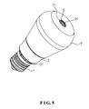
- FIG. 5 is a schematic view illustrating the present invention in an assembled form.
- FIG. 6 is a cross-sectional view of the present invention in an assembled form.
- the present invention discloses a bulb lamp structure, which comprises a base 1 , a seat 2 , a circuit board 3 for driving light-emitting diode (LED) chips, a plurality of chips 4 on which LEDs are mounted, a heat dissipater 5 , a double-sided board 6 connecting between the chips 4 and the circuit board 3 , and a bulb housing 7 .
- LED light-emitting diode
- the base 1 is coupled to a lower end of the seat 2 .
- the seat 2 is provided with one or more air inlet openings, and in the instant embodiment, air inlet openings 21 are formed in and distributed along a lower rim of the seat 2 that is adjacent to the base 1 .
- the heat dissipater 5 has a lower portion forming an annular hood 51 that corresponds to and is received and mounted in the seat 2 .
- Arranged on an upper end of the annular hood 51 is a plurality of plate-like substrates 52 that extends upward and is spaced from each other.
- the plate-like substrates 52 circumferentially surround and delimit a chamber 53 .
- the chamber 53 is shaped to show a configuration that is gradually reduced from bottom to top so that a top end of the chamber 53 is convergent to form an air outlet opening.
- the bottom of the chamber 53 is in communication with the air inlet openings 21 of the seat 2 .
- the circuit board 3 is arranged, in a longitudinal direction, in the seat 2 and has an upper end thereof positioned in abutting engagement with the heat dissipater 5 and a lower end connected to the base 1 .
- the chips 4 are respectively set on and mounted to outside surfaces of the plate-like substrates 52 .
- the double-sided board 6 is fit to and encompasses the heat dissipater 5 and is connected to the chips 4 and the circuit board 3 .
- the bulb housing 7 encloses and houses the chips 4 and is coupled to the seat 2 .
- the bulb housing 7 comprises a ventilation hole 71 formed in a central portion of a top end thereof and corresponding exactly to the air outlet opening that is located in an upper end of the heat dissipater 5 .
- a cover plate 8 is further provided above the double-sided board 6 .
- the cover plate 8 is in the form of an annular cover that is fit over and encompasses the plate-like substrates 52 to be located above the double-sided board 6 .
- Each of the plate-like substrates 52 of the heat dissipater 5 has an upper end that is constrained in position by a cap 9 .
- the cap 9 comprises air passage openings 91 formed therein and in communication with the chamber 53 .
- the air passage openings 91 are arranged to extend to a site corresponding to the ventilation hole 71 of the bulb housing 7 .
- the LED bulb lamp so structured provides the following efficacy:
- the bulb lamp has excellent effect of heat dissipation.
- the heat dissipater 5 is composed of a plurality of plate-like substrates 52 on which the chips 4 are mounted such that spacing gaps among the plate-like substrates 52 may serve as airflow passages.
- the plate-like substrates 52 are arranged in the longitudinal direction to circumferentially surround and delimit the chamber 53 of which the bottom is in communication with the air inlet openings 21 of the seat 2 and the top is in communication with the ventilation hole 71 of the bulb housing 7 .
- the chamber is shaped to show an expanded top and a reduced bottom so as to define an airflow channel therein, whereby when the LEDs are put into operation, high temperature air inside the bulb housing 7 moves through the airflow passages and then the airflow channel to move out of the bulb housing.
- heat dissipation of the LEDs according to the present invention is achieved through airflows.
- the outside configuration is closer to that of a traditional incandescent bulb.
- the plate-like substrates 52 of the heat dissipater 5 are arranged in the longitudinal direction and are distributed in circumferential direction so that the chips 4 are arranged in a three-dimensional form inside the bulb housing 7 .
- a bulb lamp constructed in this way does not show an enlarged seat in the outside configuration thereof so that the outside configuration is much closer to a traditional incandescent bulb.
- the chips 4 are arranged in a three-dimensional form in the bulb housing 7 . This, compared to a planar arrangement of chips of a conventional LED bulb lamp, provides an enlarged illumination angle for the entire LED bulb lamp and a widened range of illumination may be achieved.
- the present invention provides an LED bulb lamp that can effectively and better handles heat dissipation issues of chips of an LED bulb lamp and also achieves a large illumination angle of an LED bulb lamp and provides an efficacy of facilitating automatic production.
Landscapes
- Engineering & Computer Science (AREA)
- General Engineering & Computer Science (AREA)
- Microelectronics & Electronic Packaging (AREA)
- Physics & Mathematics (AREA)
- Optics & Photonics (AREA)
- Non-Portable Lighting Devices Or Systems Thereof (AREA)
- Arrangement Of Elements, Cooling, Sealing, Or The Like Of Lighting Devices (AREA)
Abstract
Description
Claims (9)
Applications Claiming Priority (1)
| Application Number | Priority Date | Filing Date | Title |
|---|---|---|---|
| PCT/CN2014/089864 WO2016065566A1 (en) | 2014-10-30 | 2014-10-30 | Bulb lamp structure |
Publications (2)
| Publication Number | Publication Date |
|---|---|
| US20160320047A1 US20160320047A1 (en) | 2016-11-03 |
| US10018347B2 true US10018347B2 (en) | 2018-07-10 |
Family
ID=55856386
Family Applications (1)
| Application Number | Title | Priority Date | Filing Date |
|---|---|---|---|
| US15/108,781 Active - Reinstated 2035-02-16 US10018347B2 (en) | 2014-10-30 | 2014-10-30 | Bulb lamp structure having a bulb housing, heat dissipater and inlet and outlet ventilation holes formed in seat and upper portion of bulb housing |
Country Status (3)
| Country | Link |
|---|---|
| US (1) | US10018347B2 (en) |
| JP (1) | JP6260978B2 (en) |
| WO (1) | WO2016065566A1 (en) |
Families Citing this family (7)
| Publication number | Priority date | Publication date | Assignee | Title |
|---|---|---|---|---|
| US10928056B2 (en) * | 2016-06-23 | 2021-02-23 | Opple Lighting Co., Ltd. | Lighting device |
| CN108826037A (en) * | 2018-08-24 | 2018-11-16 | 德清鼎辉照明有限公司 | Bulb lamp |
| CN108799866A (en) * | 2018-08-24 | 2018-11-13 | 德清鼎辉照明有限公司 | A kind of bulb lamp |
| CN108870114A (en) * | 2018-08-24 | 2018-11-23 | 德清鼎辉照明有限公司 | A kind of bulb lamp of built-in LED patch |
| CN108980649A (en) * | 2018-08-24 | 2018-12-11 | 德清鼎辉照明有限公司 | Surface-mount LED lamp core |
| CN109519774B (en) * | 2018-11-13 | 2020-12-25 | 温州市华伦电器有限公司 | Lamp holder |
| WO2023142522A1 (en) * | 2022-01-28 | 2023-08-03 | 杭州杭科光电集团股份有限公司 | Line lamp |
Citations (6)
| Publication number | Priority date | Publication date | Assignee | Title |
|---|---|---|---|---|
| US7513653B1 (en) * | 2007-12-12 | 2009-04-07 | Fu Zhun Precision Industry (Shen Zhen) Co., Ltd. | LED lamp having heat sink |
| US20110115358A1 (en) * | 2009-11-16 | 2011-05-19 | Led Folio Corporation | Led bulb having side-emitting led modules with heatsinks therebetween |
| US8143769B2 (en) * | 2008-09-08 | 2012-03-27 | Intematix Corporation | Light emitting diode (LED) lighting device |
| US8487518B2 (en) * | 2010-12-06 | 2013-07-16 | 3M Innovative Properties Company | Solid state light with optical guide and integrated thermal guide |
| US8926131B2 (en) * | 2012-05-08 | 2015-01-06 | 3M Innovative Properties Company | Solid state light with aligned light guide and integrated vented thermal guide |
| US8952613B2 (en) * | 2009-05-12 | 2015-02-10 | Leroy E. Anderson | LED room light |
Family Cites Families (11)
| Publication number | Priority date | Publication date | Assignee | Title |
|---|---|---|---|---|
| JP2010135181A (en) * | 2008-12-04 | 2010-06-17 | Sharp Corp | Illuminating device |
| CN101865373B (en) * | 2009-04-20 | 2013-09-04 | 富准精密工业(深圳)有限公司 | Light-emitting diode lamp |
| CN202065708U (en) * | 2011-02-14 | 2011-12-07 | 浙江迈勒斯照明有限公司 | LED (light-emitting diode) lamp with hollow cooling base |
| US10030863B2 (en) * | 2011-04-19 | 2018-07-24 | Cree, Inc. | Heat sink structures, lighting elements and lamps incorporating same, and methods of making same |
| CN202091833U (en) * | 2011-05-05 | 2011-12-28 | 鹤山市银雨照明有限公司 | LED (Light-Emitting Diode) lamp bulb with fan |
| US20130051003A1 (en) * | 2011-08-26 | 2013-02-28 | Chenjun Fan | LED Lighting Device with Efficient Heat Removal |
| CN202432304U (en) * | 2011-12-30 | 2012-09-12 | 上海顿格电子贸易有限公司 | High-angle light-emitting lamp (LED) bulb lamp with air natural internal and external convection radiation function |
| CN103353071A (en) * | 2013-07-05 | 2013-10-16 | 立达信绿色照明股份有限公司 | LED lamp emitting light in large angle |
| CN203489092U (en) * | 2013-08-23 | 2014-03-19 | 张榳芳 | Light-emitting diode (LED) lamp structure allowing wide-angle lighting |
| CN103672526B (en) * | 2013-12-30 | 2016-05-04 | 蔡干强 | A kind of bulb of good heat dissipation effect |
| CN203810319U (en) * | 2014-04-22 | 2014-09-03 | 惠州市华阳光电技术有限公司 | Connecting structure for power source board and light source board of LED bulb lamp |
-
2014
- 2014-10-30 JP JP2016543604A patent/JP6260978B2/en active Active
- 2014-10-30 US US15/108,781 patent/US10018347B2/en active Active - Reinstated
- 2014-10-30 WO PCT/CN2014/089864 patent/WO2016065566A1/en active Application Filing
Patent Citations (6)
| Publication number | Priority date | Publication date | Assignee | Title |
|---|---|---|---|---|
| US7513653B1 (en) * | 2007-12-12 | 2009-04-07 | Fu Zhun Precision Industry (Shen Zhen) Co., Ltd. | LED lamp having heat sink |
| US8143769B2 (en) * | 2008-09-08 | 2012-03-27 | Intematix Corporation | Light emitting diode (LED) lighting device |
| US8952613B2 (en) * | 2009-05-12 | 2015-02-10 | Leroy E. Anderson | LED room light |
| US20110115358A1 (en) * | 2009-11-16 | 2011-05-19 | Led Folio Corporation | Led bulb having side-emitting led modules with heatsinks therebetween |
| US8487518B2 (en) * | 2010-12-06 | 2013-07-16 | 3M Innovative Properties Company | Solid state light with optical guide and integrated thermal guide |
| US8926131B2 (en) * | 2012-05-08 | 2015-01-06 | 3M Innovative Properties Company | Solid state light with aligned light guide and integrated vented thermal guide |
Also Published As
| Publication number | Publication date |
|---|---|
| JP6260978B2 (en) | 2018-01-17 |
| WO2016065566A1 (en) | 2016-05-06 |
| US20160320047A1 (en) | 2016-11-03 |
| JP2017501548A (en) | 2017-01-12 |
Similar Documents
| Publication | Publication Date | Title |
|---|---|---|
| US10018347B2 (en) | Bulb lamp structure having a bulb housing, heat dissipater and inlet and outlet ventilation holes formed in seat and upper portion of bulb housing | |
| US8430528B2 (en) | LED bulb | |
| US8246215B2 (en) | LED bulb | |
| US9797580B2 (en) | LED light fixture | |
| KR101135721B1 (en) | Socket-typed LED light apparatus | |
| US8500304B2 (en) | LED bulb | |
| US8317372B2 (en) | LED bulb | |
| JP2010103454A (en) | Circular-structure led lighting illumination lamp using nanospreader | |
| TW201323774A (en) | Solid-state lamps with improved radial emission and thermal performance | |
| TW201303207A (en) | Illumination device | |
| US20110222283A1 (en) | Led lamp and cooling structure thereof | |
| US10197263B2 (en) | Omnidirectional light emission LED lamp | |
| CN103423613A (en) | Light emitting diode lamp | |
| TWM472161U (en) | Light emitting diode lamp | |
| US20140085908A1 (en) | Led lamp structure having free convection cooling | |
| JP5746897B2 (en) | LED lighting device | |
| WO2015169254A1 (en) | Omnidirectional illuminating led bulb | |
| TW201307731A (en) | Light emitting diode bulb | |
| TWI558947B (en) | Multi-directional light bulb | |
| US9423099B2 (en) | LED lamp having reflector with high heat dissipation rate | |
| TW201506312A (en) | Light-emitting device | |
| US20110181164A1 (en) | Led lamp for wide area lighting | |
| KR101876948B1 (en) | Illuminating lamp | |
| US9416953B2 (en) | LED lighting apparatus | |
| US20130128596A1 (en) | Led bulb |
Legal Events
| Date | Code | Title | Description |
|---|---|---|---|
| AS | Assignment |
Owner name: MAINHOUSE (XIAMEN) ELECTRONICS CO., LTD., CHINA Free format text: ASSIGNMENT OF ASSIGNORS INTEREST;ASSIGNORS:ZHOU, NANQING;WU, RONGKUI;REEL/FRAME:039034/0799 Effective date: 20160607 |
|
| STCF | Information on status: patent grant |
Free format text: PATENTED CASE |
|
| FEPP | Fee payment procedure |
Free format text: MAINTENANCE FEE REMINDER MAILED (ORIGINAL EVENT CODE: REM.); ENTITY STATUS OF PATENT OWNER: SMALL ENTITY |
|
| LAPS | Lapse for failure to pay maintenance fees |
Free format text: PATENT EXPIRED FOR FAILURE TO PAY MAINTENANCE FEES (ORIGINAL EVENT CODE: EXP.); ENTITY STATUS OF PATENT OWNER: SMALL ENTITY |
|
| STCH | Information on status: patent discontinuation |
Free format text: PATENT EXPIRED DUE TO NONPAYMENT OF MAINTENANCE FEES UNDER 37 CFR 1.362 |
|
| FP | Lapsed due to failure to pay maintenance fee |
Effective date: 20220710 |
|
| PRDP | Patent reinstated due to the acceptance of a late maintenance fee |
Effective date: 20221204 |
|
| FEPP | Fee payment procedure |
Free format text: PETITION RELATED TO MAINTENANCE FEES FILED (ORIGINAL EVENT CODE: PMFP); ENTITY STATUS OF PATENT OWNER: SMALL ENTITY Free format text: PETITION RELATED TO MAINTENANCE FEES GRANTED (ORIGINAL EVENT CODE: PMFG); ENTITY STATUS OF PATENT OWNER: SMALL ENTITY Free format text: SURCHARGE, PETITION TO ACCEPT PYMT AFTER EXP, UNINTENTIONAL. (ORIGINAL EVENT CODE: M2558); ENTITY STATUS OF PATENT OWNER: SMALL ENTITY |
|
| MAFP | Maintenance fee payment |
Free format text: PAYMENT OF MAINTENANCE FEE, 4TH YR, SMALL ENTITY (ORIGINAL EVENT CODE: M2551); ENTITY STATUS OF PATENT OWNER: SMALL ENTITY Year of fee payment: 4 |
|
| STCF | Information on status: patent grant |
Free format text: PATENTED CASE |