RU2755134C1 - Method for illuminating a target to ensure the use of ammunition with a laser semi-active homing head - Google Patents
Method for illuminating a target to ensure the use of ammunition with a laser semi-active homing head Download PDFInfo
- Publication number
- RU2755134C1 RU2755134C1 RU2021104397A RU2021104397A RU2755134C1 RU 2755134 C1 RU2755134 C1 RU 2755134C1 RU 2021104397 A RU2021104397 A RU 2021104397A RU 2021104397 A RU2021104397 A RU 2021104397A RU 2755134 C1 RU2755134 C1 RU 2755134C1
- Authority
- RU
- Russia
- Prior art keywords
- target
- quadcopter
- illuminator
- laser
- coordinates
- Prior art date
Links
Images
Classifications
-
- F—MECHANICAL ENGINEERING; LIGHTING; HEATING; WEAPONS; BLASTING
- F41—WEAPONS
- F41G—WEAPON SIGHTS; AIMING
- F41G5/00—Elevating or traversing control systems for guns
-
- F—MECHANICAL ENGINEERING; LIGHTING; HEATING; WEAPONS; BLASTING
- F41—WEAPONS
- F41G—WEAPON SIGHTS; AIMING
- F41G7/00—Direction control systems for self-propelled missiles
- F41G7/34—Direction control systems for self-propelled missiles based on predetermined target position data
Landscapes
- Engineering & Computer Science (AREA)
- General Engineering & Computer Science (AREA)
- Chemical & Material Sciences (AREA)
- Combustion & Propulsion (AREA)
- Aiming, Guidance, Guns With A Light Source, Armor, Camouflage, And Targets (AREA)
Abstract
Description
Изобретение относится к средствам боевого обеспечения применения высокоточного оружия, в частности артиллерийских снарядов, управляемых ракет и авиационных бомб с лазерной полуактивной головкой самонаведения (ГСН).The invention relates to means of combat support for the use of high-precision weapons, in particular artillery shells, guided missiles and aerial bombs with a semi-active laser homing head (GOS).
Известен способ одновременного наведения управляемых ракет с лазерной полуактивной ГСН [1]. Способ включает определение координат целей с помощью наземных лазерных целеуказателей, расчет и закладку в каждую управляемую ракету (УР) полетного задания и времени включения целеуказателя в режим подсвета. В полете УР устанавливает канал цифровой радиосвязи с целеуказателем и передает по нему сигнал включения. Для исключения ложного наведения и перепутывания целей каждой УР и соответствующему целеуказателю (позиции разведки и целеуказания) назначают адреса и коды частот лазерного подсвета, которыми они обмениваются по установленному каналу радиосвязи.The known method of simultaneous guidance of guided missiles with a laser semi-active seeker [1]. The method includes determining the coordinates of targets using ground-based laser designators, calculating and inserting a flight mission into each guided missile (UR) and the time when the target designator is switched on to the illumination mode. In flight, the UR establishes a digital radio communication channel with a target designator and transmits an activation signal through it. To exclude false guidance and confusion of targets, each missile launcher and the corresponding target designator (reconnaissance and target designation positions) are assigned addresses and frequency codes of the laser illumination, which they exchange over the established radio communication channel.
Недостатками способа являются сложные организационно-техническая структура и алгоритм работы реализующий его системы, что затрудняет согласованное взаимодействие компонентов и снижает эффективность боевого применения способа. Частично устранить недостатки можно при переносе ряда компонентов на носители воздушного базирования. Однако в способе [1] эта возможность не рассматривается.The disadvantages of this method are the complex organizational and technical structure and the algorithm of the system that implements it, which complicates the coordinated interaction of the components and reduces the effectiveness of the combat application of the method. The disadvantages can be partially eliminated by transferring a number of components to airborne carriers. However, in the method [1], this possibility is not considered.
Известен способ стрельбы управляемыми снарядами с лазерной полуактивной ГСН [2]. Данный способ, предназначенный для применения в батарейных артиллерийских комплексах залпового поражения целей, во многом аналогичен способу [1] и наследует его недостатки. Существенным отличием способа является автономность самонаводящихся снарядов в полете (в отличие от УР с установленными каналами радиосвязи) при наземном размещении всех компонентов в основном варианте его исполнения. Предусмотрен дополнительный вариант с установкой целеуказателей со своими пультами разведчика на подвижных носителях (например, беспилотных летательных аппаратах, БЛА), перемещающихся по траекториям, задаваемым дистанционно командиром батареи. Однако декларируется лишь принципиальная возможность такого варианта без конкретных мер по его реализации. При этом остается открытым главный вопрос о составе и оснащении группы воздушных носителей (по числу целеуказателей или иначе) и алгоритме управления ею.The known method of firing guided projectiles with a semi-active laser seeker [2]. This method, intended for use in battery artillery complexes of salvo destruction of targets, is in many respects similar to the method [1] and inherits its disadvantages. A significant difference of the method is the autonomy of homing projectiles in flight (as opposed to a missile launcher with installed radio communication channels) with the ground placement of all components in its basic version. An additional option is provided with the installation of target designators with their own reconnaissance consoles on mobile carriers (for example, unmanned aerial vehicles, UAVs) moving along trajectories set remotely by the battery commander. However, only the fundamental possibility of such an option is declared without specific measures for its implementation. At the same time, the main question about the composition and equipment of the group of air carriers (by the number of target designators or otherwise) and the algorithm for controlling it remains open.
Наиболее близким к заявляемому изобретению является способ [3], в соответствии с которым в район цели запускают БЛА, оснащенный телевизионной камерой с автоматом сопровождения, лазерным целеуказателем-дальномером (ЛЦД), гиростабилизированной платформой (ГСП), приводами разворота ЛЦД и телекамеры, автопилотом с инерциальной и спутниковой системами навигации для координатной привязки целеуказателя и отработки заданного маршрута полета, средств цифровой радиосвязи для передачи бортовых данных о топографических координатах цели на огневую позицию. По полученным данным и известным топографическим координатам позиции производят расчет, реализацию установок стрельбы и выстрел снаряда. В момент выстрела формируют и по цифровой радиосвязи передают на борт БЛА команду включения ЛЦД в режим подсвета цели.The closest to the claimed invention is the method [3], according to which a UAV equipped with a television camera with an automatic tracking machine, a laser target designator-rangefinder (LCD), a gyro-stabilized platform (GSP), an LCD reversal drive and a television camera, an autopilot with inertial and satellite navigation systems for the coordinate referencing of the target designator and testing the specified flight route, digital radio communications for transmitting onboard data on the topographic coordinates of the target to the firing position. Based on the data obtained and the known topographic coordinates of the position, the calculation, the implementation of the firing settings and the firing of the projectile are carried out. At the moment of the shot, a command to turn on the LCD into the target illumination mode is generated and transmitted to the UAV via digital radio communication.
Достоинствами способа [3] являются повышение безопасности оператора целеуказателя (снижается потребность выдвижения на передовые позиции) и расширение области применения боеприпасов с лазерной полуактивной ГСН за счет установки подсветчика (ЛЦД) на воздушный носитель (БЛА) с радиусом действия, сопоставимым с дальностью стрельбы артиллерии.The advantages of the method [3] are the increased safety of the target designator operator (the need to move to forward positions is reduced) and the expansion of the scope of ammunition with a semi-active laser seeker by installing an illuminator (LCD) on an airborne vehicle (UAV) with a range comparable to the artillery firing range.
Заметим, что по месту установки основных информационно-измерительных компонентов, участвующих в реализации, "бортовой" способ-прототип [3] является альтернативой "наземным" аналогам [1, 2].Note that at the installation site of the main information and measurement components involved in the implementation, the "onboard" prototype method [3] is an alternative to the "ground" counterparts [1, 2].
Недостатки способа [3] состоят в следующем:The disadvantages of method [3] are as follows:
1. Бортовое размещение телекамеры с автоматом сопровождения, ЛЦД, ГСП, приводов разворота, автопилота с навигационными системами и других компонентов требует использования грузоподъемных, дорогостоящих и сложных в управлении БЛА самолетного типа. Примером такого технического решения служит автоматизированная огневая система на базе БЛА [4], разработанная предприятием-патентообладателем способа [3]. Используется БЛА «Катран» разработки ОАО «Аэрокон». Другим примером является система на основе БЛА «Орлан-30» [5], разработанная ООО «Специальный технологический центр». Очевидно, что одновременное, массовое, многоцелевое применение таких БЛА в боевых условиях, где велика вероятность их уничтожения противником, невозможно.1. Onboard placement of a TV camera with an automatic tracking machine, LCD, GPS, turn drives, an autopilot with navigation systems and other components requires the use of lifting, expensive and difficult to control aircraft-type UAVs. An example of such a technical solution is an automated fire system based on a UAV [4], developed by an enterprise-patentee of the method [3]. UAV "Katran" developed by JSC "Aerokon" is used. Another example is the system based on the UAV "Orlan-30" [5], developed by LLC "Special Technological Center". It is obvious that the simultaneous, massive, multipurpose use of such UAVs in combat conditions, where there is a high probability of their destruction by the enemy, is impossible.
2. Решение задач по назначению ЛЦД (координатная привязка и подсвет наземной цели), установленного на БЛА с потолком высот 4500-5000 м, требует применения мощных генераторов лазерного излучения и совершенных оптических систем фокусировки (необходим малый угол расходимости лазерного луча). Из двух режимов ЛЦД это требование является определяющим для более продолжительного и энергоемкого режима подсвета. Его выполнение в рассматриваемых условиях представляет сложную техническую проблему.2. Solving the tasks for the purpose of the LCD (positioning and illumination of a ground target) installed on a UAV with a ceiling height of 4500-5000 m requires the use of powerful generators of laser radiation and perfect optical focusing systems (a small angle of divergence of the laser beam is required). Of the two LCD modes, this requirement is decisive for a longer and more power-consuming illumination mode. Its implementation in the considered conditions is a complex technical problem.
Задача заявляемого изобретения состоит в создании недорого, простого в реализации и пригодного для массового использования способа подсвета цели для обеспечения применения боеприпасов с лазерной полуактивной ГСН.The objective of the claimed invention is to create an inexpensive, easy to implement and suitable for mass use method of target illumination to ensure the use of ammunition with a semi-active laser seeker.
Для решения поставленной задачи в способе подсвета цели для обеспечения применения боеприпасов с лазерной полуактивной ГСН, включающем определение топографических координат целеуказателя, обнаружение и измерение сферических координат цели целеуказателем, определение по указанным топографическим и сферическим координатам топографических координат цели, определение топографических координат огневой позиции, расчет по указанным топографическим координатам цели и огневой позиции и реализацию установок стрельбы, производство выстрела боеприпаса, синхронное с моментом времени выстрела и полетным временем боеприпаса на конечном участке траектории включение по каналу цифровой радиосвязи лазерного излучения подсвета цели, установку компонентов используемых аппаратных средств на БЛА, в качестве БЛА используют квадрокоптер, выполненный с возможностью зависания над целью в режиме удержания заданных топографических координат цели, на квадрокоптер устанавливают выполненный в виде отдельного компонента лазерный подсветчик цели в надирном положении, подсветчик закрепляют на нижнем конце жесткой штанги, верхний конец штанги для компенсации угловых колебаний квадрокоптера в вертикальной плоскости с помощью шарнирного соединения крепят к днищу квадрокоптера, надирное положение подсветчика обеспечивают его самоориентированием за счет силы тяжести, при этом высоту зависания квадрокоптера над целью определяют по значениям угла расходимости лазерного луча подсветчика и минимального планового габаритного размера цели.To solve the set task in the method of target illumination to ensure the use of ammunition with a laser semi-active seeker, including determining the topographic coordinates of the target designator, detecting and measuring the spherical coordinates of the target with the target designator, determining the topographic coordinates of the target using the indicated topographic and spherical coordinates, determining the topographic coordinates of the firing position, calculating the specified topographic coordinates of the target and firing position and the implementation of firing installations, the production of a shot of ammunition, synchronous with the moment of time of the shot and the flight time of the ammunition in the final section of the trajectory, switching on the laser radiation of the target illumination via the digital radio channel, installing the components of the used hardware on the UAV, as a UAV a quadcopter is used, made with the possibility of hovering over the target in the mode of keeping the given topographic coordinates of the target, the quadcopter is installed as a separate component that laser target illuminator in the nadir position, the illuminator is fixed at the lower end of a rigid rod, the upper end of the rod to compensate for angular oscillations of the quadcopter in the vertical plane is attached to the bottom of the quadcopter using a hinge joint, the nadir position of the illuminator is provided by its self-orientation due to gravity, while the height is hovering of the quadcopter over the target is determined by the values of the angle of divergence of the laser beam of the illuminator and the minimum planned overall size of the target.
Существенные отличительные признаки заявляемого способа по сравнению с прототипом заключаются в следующем:The essential distinguishing features of the proposed method in comparison with the prototype are as follows:
1. Использование в качестве БЛА квадрокоптера, способного неподвижно зависать и удерживать заданные топографические координаты цели, обеспечивает постоянство условий устойчивой работы лазерного подсветчика и не требует последующего уточнения и отработки координат БЛА с подсветчиком на борту. При этом выведение квадрокоптера в заданную точку пространства и его удержание выполняются штатными бортовыми средствами инерциально-спутниковой навигации, радиосвязи и управления.1. The use of a quadrocopter as a UAV, capable of hovering motionlessly and holding the given topographic coordinates of the target, ensures the constancy of the conditions for stable operation of the laser illuminator and does not require further refinement and refinement of the coordinates of the UAV with the illuminator on board. In this case, the introduction of the quadrocopter to a given point in space and its retention are carried out by standard onboard means of inertial-satellite navigation, radio communication and control.
В прототипе, использующем БЛА самолетного типа, необходимо в динамике полета непрерывно определять и отрабатывать текущие параметры движения аппарата с бортовым подсветчиком (ЛЦД в режиме подсвета), отслеживая цель в поле зрения целеуказателя с помощью специального автомата сопровождения и ГСП.In a prototype using an aircraft-type UAV, it is necessary in the flight dynamics to continuously determine and work out the current movement parameters of the vehicle with an on-board illuminator (LCD in illumination mode), tracking the target in the field of view of the target designator using a special automatic tracking machine and GPS.
2. Исполнение устанавливаемого на квадрокоптер лазерного подсветчика в виде отдельного от наземного целеуказателя, автономного, однорежимного (только подсвет) компонента позволяет добиться простоты его конструкции, малых массогабаритных параметров, низкого энергопотребления и невысокой стоимости. В свою очередь, это позволяет использовать малогабаритные, малозаметные и дешевые квадрокоптеры массового производства и применения.2. The design of the laser illuminator installed on the quadcopter as a separate from the ground target designator, autonomous, single-mode (only illuminator) component allows achieving simplicity of its design, small weight and size parameters, low power consumption and low cost. In turn, this allows the use of small-sized, unobtrusive and cheap quadcopters of mass production and use.
В прототипе используемый состав бортовых средств (двухрежимный ЛЦД, телекамера с автоматом сопровождения, ГСП и др.) требует применения дорогостоящих, высокой грузоподъемности, энергоемких единичных БЛА.In the prototype, the composition of onboard facilities used (dual-mode LCD, TV camera with automatic tracking, GSP, etc.) requires the use of expensive, high carrying capacity, energy-intensive single UAVs.
3. Закрепление подсветчика на нижнем конце жесткой штанги, верхний конец которой с помощью шарнирного соединения прикреплен к днищу квадрокоптера, позволяет поддерживать конструкцию в вертикальном положении, компенсируя при зависании уклонения корпуса квадрокоптера от горизонтальной плоскости, необходимые для демпфирования ветрового воздействия. Ключевым моментом здесь является самоориентирование подсветчика в надирное положение за счет силы тяжести. Этим обеспечивается постоянство нахождения пятна лазерной засветки на верхней поверхности цели.3. Attaching the illuminator to the lower end of a rigid rod, the upper end of which is pivotally attached to the bottom of the quadcopter, allows the structure to be maintained in a vertical position, compensating for the deviation of the quadcopter body from the horizontal plane when hovering, which is necessary for damping the wind effect. The key point here is the self-orientation of the illuminator to the nadir position due to the force of gravity. This ensures the consistency of the location of the laser illumination spot on the upper surface of the target.
В прототипе такая функция не предусмотрена.The prototype does not provide such a function.
4. Высоту зависания квадрокоптера над целью определяют по значениям угла расходимости лазерного луча подсветчика β (в радианах) и минимального планового габаритного размера цели α. Для этого используется формула: Нгр=α/β, где Нгр - граничная высота, при которой протяженная диффузно отражающая цель полностью перекрывается сечением лазерного луча. При высоте квадрокоптера Н, равной или меньшей Нгр, мощность импульсного излучения, падающего на цель, есть величина постоянная и не зависит от высоты Н [6]. Этим обеспечивается максимальная постоянная плотность потока мощности отраженного сигнала и, как следствие, максимальная на протяжении всего конечного участка траектории боеприпаса текущая плотность потока мощности сигнала на входе фотопремника лазерной ГСН. Данное обстоятельство является необходимым условием высокой надежности и точности наведения боеприпаса на цель.4. The height of the quadcopter hovering over the target is determined by the values of the angle of divergence of the laser beam of the illuminator β (in radians) and the minimum planned overall size of the target α. For this, the formula is used: H gr = α / β, where H gr is the boundary height at which an extended diffusely reflecting target is completely covered by the cross section of the laser beam. When the height of the quadcopter H equal or less than H gr , the power of the pulsed radiation falling on the target is a constant value and does not depend on the height H [6]. This ensures the maximum constant power flux density of the reflected signal and, as a consequence, the maximum current signal power flux density at the input of the laser seeker photoreporter throughout the entire final section of the munition trajectory. This circumstance is a necessary condition for high reliability and accuracy of aiming the ammunition at the target.
В прототипе такая задача не рассматривается.This task is not considered in the prototype.
Указанные отличительные признаки обеспечивают достижение технического результата, заключающегося в простоте реализации и расширении области применения лазерного подсвета целей для высокоточных самонаводящихся боеприпасовThese distinctive features ensure the achievement of the technical result, which consists in the ease of implementation and expansion of the scope of laser illumination of targets for high-precision homing ammunition
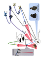
Заявляемое изобретение иллюстрирует Фиг. 1 - Схема использования способа при применении артиллерийских и авиационных самонаводящихся боеприпасов, где:The claimed invention is illustrated in FIG. 1 - Scheme of using the method when using artillery and aviation homing ammunition, where:
ЛП - лазерный подсветчик;LP - laser illuminator;
УАС - управляемый артиллерийский снаряд;UAS - guided artillery shell;
САУ - самоходная артиллерийская установка;ACS - self-propelled artillery installation;
ППУОА - передвижной пункт управления огнем артиллерии;PPUOA - mobile artillery fire control point;
КАБ - корректируемая авиационная бомба;KAB - corrected aerial bomb;
УАвР - управляемая авиационная ракета "воздух-земля";UAVR - guided air-to-ground missile;
ЛА1, ЛА2 - летательные аппараты - носители самонаводящихся боеприпасов.LA1, LA2 - aircraft - carriers of homing ammunition.
Примечание - Голубым цветом показан канал цифровой радиосвязи расчета военнослужащих с квадрокоптером; черным - с ППУОА, ЛА1, ЛА2; оранжевым цветом условно показано прямое и обратное (отраженное) излучение лазерного подсветчика.Note - The blue color shows the digital radio communication channel of the calculation of military personnel with a quadrocopter; black - with PPUOA, LA1, LA2; orange color conventionally shows the forward and backward (reflected) radiation of the laser illuminator.
Рассмотрим работу и возможность реализации заявляемого способа. Рассмотрение начнем с задачи обслуживания стрельбы артиллерии (Фиг. 1).Consider the work and the possibility of implementing the proposed method. We begin our consideration with the task of servicing artillery fire (Fig. 1).
Работу способа обеспечивает расчет военнослужащих в составе корректировщика артиллерийского огня и оператора БЛА (квадрокоптера). Расчет занимает позицию на расстоянии от линии боевого соприкосновения, позволяющем вести обнаружение и наблюдение целей. Военнослужащих расчета оснащают носимыми средствами навигации и цифровой радиосвязи, а также пультами. Аналогичными средствами и пультом в возимом исполнении оснащается огневая позиция. Арткорректировщик также снабжен целеуказателем, имеющим в своем составе визирный канал и канал измерения сферических координат цели (дальности, углов азимута и места). В качестве целеуказателя может использоваться, например, прибор разведки ПДУ-4 производства АО «ЦНИИТОЧМАШ».The operation of the method is ensured by the calculation of military personnel as part of an artillery fire spotter and a UAV (quadcopter) operator. The crew takes a position at a distance from the line of contact, allowing the detection and observation of targets. The military personnel of the calculation are equipped with portable navigation and digital radio communications, as well as with consoles. The firing position is equipped with similar means and a remote control in a transportable version. The artillery spotter is also equipped with a target designator, which includes a sighting channel and a channel for measuring the spherical coordinates of the target (range, azimuth and elevation angles). For example, a PDU-4 reconnaissance device manufactured by TsNIITOCHMASH JSC can be used as a target designator.
С помощью средств навигации определяют топографические координаты целеуказателя (арткорректировщика) и орудия на огневой позиции. В качестве носимого и возимого вариантов этих средств могут использоваться, например, модули спутниковой и инерциально-магнитной навигации соответственно из состава индивидуального приборного оснащения военнослужащих-операторов и бортовой системы управления роботизированной платформы робототехнического комплекса [7].Using the navigation aids, the topographic coordinates of the target designator (artillery spotter) and the guns at the firing position are determined. As a wearable and transportable version of these means can be used, for example, modules of satellite and inertial-magnetic navigation, respectively, from the individual instrumentation of military operators and the on-board control system of the robotic platform of the robotic complex [7].
Средства цифровой радиосвязи обеспечивают обмен данными и управляющими командами между подключенными к ним пультами военнослужащих расчета и пультом огневой позиции, а также речевыми сообщениями между военнослужащими при значительном удалении друг от друга. Здесь также могут задействоваться модули радиосвязи из состава робототехнического комплекса [7]. Модули образуют локальную высокоскоростную динамическую MANET-сеть, например, на основе известного стандарта 802.11/b/g/n и его модификаций с использованием широкодоступных комплектующих.Means of digital radio communication ensure the exchange of data and control commands between the military crew consoles connected to them and the firing position console, as well as voice messages between the military personnel at a considerable distance from each other. It can also use radio communication modules from the robotic complex [7]. The modules form a local high-speed dynamic MANET network, for example, based on the well-known 802.11 / b / g / n standard and its modifications using widely available components.
Реализация способа требует синхронизации действий его компонентов. Это достигается работой пультов в единой шкале точного времени (едином компьютерном времени по терминологии способа-прототипа [3]), которая автоматически устанавливается и распространяется другим компонентам модулями спутниковой навигации при приеме сигналов спутников. Существующие навигационные модули обеспечивают формирование временной шкалы относительно единого всемирного времени UTC с погрешностью не более 0,1 мкс, что вполне достаточно для качественного решения рассматриваемой задачи.Implementation of the method requires synchronization of the actions of its components. This is achieved by the operation of the consoles in a single precise time scale (uniform computer time in the terminology of the prototype method [3]), which is automatically installed and distributed to other components by satellite navigation modules when receiving satellite signals. The existing navigation modules provide the formation of a time scale relative to the universal universal time UTC with an error of no more than 0.1 μs, which is quite sufficient for a qualitative solution of the problem under consideration.
При обнаружении цели и измерении ее сферических координат целеуказателем, координаты которого известны, в пульте арткорректировщика рассчитывают топографические координаты цели, значения которых по цифровой радиосвязи транслируют в пульты оператора БЛА и огневой позиции.When a target is detected and its spherical coordinates are measured by a target designator, the coordinates of which are known, the topographic coordinates of the target are calculated in the control panel of the art corrector, the values of which are transmitted via digital radio to the control panels of the UAV operator and the firing position.
Заметим, что помимо используемых здесь топографических координат на местности в зависимости от потребностей и условий могут использоваться другие топо- и геоцентрические системы координат (например, прямоугольные гринвичская, абсолютная и др.).Note that in addition to the topographic coordinates used here on the ground, depending on the needs and conditions, other topo- and geocentric coordinate systems can be used (for example, rectangular Greenwich, absolute, etc.).
При получении координат цели в пульте огневой позиции по известным координатам орудия, баллистическим и метеоданным вычисляют установки стрельбы, которые с использованием средств ориентирования реализуют путем наведения заряженного орудия.When receiving the coordinates of the target in the control panel of the firing position according to the known coordinates of the gun, ballistic and meteorological data, the firing settings are calculated, which, using the orientation means, are realized by aiming the loaded gun.
Основным компонентом способа является квадрокоптер с бортовым лазерным подсветчиком в надирном положении. По полученным координатам цели оператор БЛА с помощью пульта по подключенному к нему штатному каналу радиосвязи с квадрокоптером заблаговременно или непосредственно перед выстрелом орудия выводит квадрокоптер в точку удержания координат и зависания над целью на заданной высоте в ожидании команды включения излучения подсвета.The main component of the method is a quadcopter with an onboard laser illuminator in the nadir position. According to the obtained coordinates of the target, the UAV operator, using the remote control, via the standard radio communication channel with the quadcopter connected to it, in advance or immediately before firing the gun, takes the quadcopter to the point of holding coordinates and hovering over the target at a given height, waiting for the command to turn on the illumination radiation.
Высота Н, верхний предел которой равен граничному значению Нгр, задается исходя из требования безопасности квадрокоптера (малозаметность с земли, минимальное воздействие ударной волны при подрыве цели самонаводящимся боеприпасом) и одновременно из условия соответствия диаметра пятна засветки (не более) минимальному габаритному размеру цели α. Выполнить оба ограничения можно, если приравнять безопасную высоту к граничной высоте Нгр, обеспечив соответствующий угол расходимости β лазерного излучения подсветчика. Поясним это числовым примером.Height H, the upper limit of which is equal to the boundary value of H gr , is set based on the safety requirements of the quadrocopter (stealth from the ground, minimal impact of a shock wave when a target is blasted by a homing ammunition) and at the same time from the condition that the spot diameter (no more than) corresponds to the minimum overall size of the target α ... Both restrictions can be fulfilled if the safe height is equated to the boundary height H gr , providing the appropriate divergence angle β of the laser radiation of the illuminator. Let us explain this with a numerical example.
Примем Нгр=500 м и α=2,2 м (типовая ширина бронеавтомобиля). С использованием формулы п. 4 отличительных признаков легко рассчитать, что соответствующий угол β должен иметь значение не более 4,4 мрад (15 угл. мин.). При α=3,6 м (ширина танка) это значение равно 7,2 мрад (25 угл. мин.). Результаты расчетов свидетельствуют о достаточно мягких требованиях к оптической системе фокусировки подсветчика.Let's take H gr = 500 m and α = 2.2 m (typical width of an armored car). Using the formula of item 4 of the distinctive features, it is easy to calculate that the corresponding angle β should have a value of no more than 4.4 mrad (15 arc min.). With α = 3.6 m (tank width), this value is 7.2 mrad (25 arc min.). The calculation results indicate rather mild requirements for the optical focusing system of the illuminator.
Подсветчик с такой направленностью излучения может быть реализован, например, на основе малогабаритного образца линейки лазерных целеуказателей-дальномеров АО «НИИ «Полюс» им. М.Ф. Стельмаха». Упростив оптическую систему образца (до указанных значений угла расходимости), устранив из конструкции дальномерный канал и подключив к бортовой системе электропитания квадрокоптера, можно изготовить лазерный подсветчик с массогабаритными характеристиками, укладывающимися в грузоподъемность малогабаритных квадрокоптеров.The illuminator with such directivity of radiation can be realized, for example, on the basis of a small-sized sample of a line of laser target designators-rangefinders of JSC "Research Institute" Polyus "named after M.F. Stelmakh ". Simplifying the optical system of the sample (up to the specified values of the divergence angle), removing the rangefinder channel from the design and connecting it to the onboard power supply system of the quadcopter, it is possible to make a laser illuminator with weight and size characteristics that fit into the carrying capacity of small-sized quadcopters.
В качестве квадрокоптера-носителя подсветчика могут применяться, например, широкодоступные квадрокоптеры производства компании DJI. Запуск квадрокоптера выполняют с позиции, занимаемой расчетом, или с огневой позиции. По окончании подсвета квадрокоптер возвращают на исходную позицию. При использовании простейшего варианта подсветчика и миниатюрного "любительского" квадрокоптера он может рассматриваться как одноразовый компонент, не требующий возвращения на исходную позицию.As a quadcopter-carrier of the illuminator, for example, widely available quadcopters manufactured by DJI can be used. The quadcopter is launched from the position occupied by the crew, or from the firing position. At the end of the illumination, the quadcopter is returned to its original position. When using the simplest version of the illuminator and a miniature "amateur" quadcopter, it can be considered as a disposable component that does not require returning to its original position.
Производство выстрела выполняют после выработки в пульте огневой позиции разрешения на выстрел, формируемого после проверки возможности попадания отраженного от цели лазерного излучения подсветчика (его координаты и параметры излучения на огневой позиции известны) в поле зрения фотоприемника ГСН боеприпаса при подлете к цели.The firing of a shot is carried out after the permission for a shot is generated in the control panel of the firing position, which is formed after checking the possibility of hitting the laser radiation of the illuminator reflected from the target (its coordinates and radiation parameters at the firing position are known) in the field of view of the photodetector of the seeker of the ammunition when approaching the target.
В момент выстрела в пульте огневой позиции вырабатывается и по цифровой радиосвязи через пульт оператора БЛА передается на борт квадрокоптера команда включения подсветчика на излучение. Команда содержит время начала и продолжительность подсветки. По достижении заданного времени происходит исполнение команды.At the moment of firing, the command to turn on the illumination for radiation is sent to the quadcopter board via digital radio communication through the UAV operator's console. The command contains the start time and duration of the backlight. Upon reaching the specified time, the command is executed.
Необходимая продолжительность подсвета цели, проводимого с борта БЛА, достаточно велика и может достигать, например, 12 с (см. патент [2]). В то же время длительность процедуры измерения сферических координат цели арткорректировщиком с помощью наземного целеуказателя, использующего лазерное излучение в канале измерения дальности, занимает доли секунды, т.е. существенно меньше продолжительности подсвета. Этим обеспечивается безопасность военнослужащих расчета, т.к. вероятность обнаружения бортового источника излучения и уничтожения его носителя-квадрокоптера существенно выше, чем наземного. Очевидно, что потеря квадрокоптера несравненно менее значима, чем потери личного состава.The required duration of target illumination conducted from the UAV is rather long and can reach, for example, 12 s (see patent [2]). At the same time, the duration of the procedure for measuring the spherical coordinates of a target by an artillery spotter using a ground target designator using laser radiation in the range measurement channel takes a fraction of a second, i.e. significantly shorter illumination duration. This ensures the safety of the servicemen of the calculation, tk. the probability of detecting an airborne radiation source and destroying its carrier-quadcopter is significantly higher than that of a ground-based one. Obviously, the loss of a quadcopter is incomparably less significant than the loss of personnel.
Техническая реализация пультов военнослужащих и огневой позиции не вызывает сложности, поскольку в их качестве могут использоваться штатные носимые персональные компьютеры командиров подразделений нижнего тактического звена, находящиеся на снабжении Вооруженных сил.The technical implementation of the consoles for military personnel and the firing position does not cause difficulty, since they can be used as standard wearable personal computers of commanders of lower tactical units that are supplied by the Armed Forces.
Все сказанное по задачам и условиям боевой работы в полной мере относится к передовым авианаводчикам. Отличие заключается в "переносе" огневой позиции на воздушный носитель самонаводящихся боеприпасов (см. Фиг. 1) и, как следствие, в необходимости оснащения авианаводчика специальной цифровой радиостанцией для связи с бортовой аппаратурой и экипажем летательного аппарата.Everything that has been said about the tasks and conditions of combat work fully applies to advanced aircraft controllers. The difference lies in the "transfer" of the firing position to the air carrier of homing ammunition (see Fig. 1) and, as a consequence, in the need to equip the airborne gunner with a special digital radio station for communication with the onboard equipment and the crew of the aircraft.
Таким образом, заявляемый способ может быть реализован и обеспечивает простоту реализации и расширение области применения лазерного подсвета целей для высокоточных самонаводящихся боеприпасов.Thus, the claimed method can be implemented and provides ease of implementation and expansion of the scope of laser illumination of targets for high-precision homing ammunition.
Источники информации:Sources of information:
1. Патент RU 2657356.1. Patent RU 2657356.
2. Патент RU 2716462.2. Patent RU 2716462.
3. Патент RU 2584210.3. Patent RU 2584210.
4. Автоматизированная боевая система на базе беспилотного летательного аппарата. 12 января 2018. - Режим доступа: https://zen.yandex.ru/media/btvt/avtomatizirovannaia-ognevaia-sistema-na-baze-bespilotnogo-letatelnogo-apparata-5a5918c18139baa70ab67cac.4. An automated combat system based on an unmanned aerial vehicle. January 12, 2018. - Access mode: https://zen.yandex.ru/media/btvt/avtomatizirovannaia-ognevaia-sistema-na-baze-bespilotnogo-letatelnogo-apparata-5a5918c18139baa70ab67cac.
5. Орлан-30 - лучший друг артиллерии. - Режим доступа: https://zvezdaweekly.ru/news/20206251815-uqqk7.html.5. Orlan-30 is the best friend of artillery. - Access mode: https://zvezdaweekly.ru/news/20206251815-uqqk7.html.
6. Дальность действия лазерной локации. - Режим доступа: https://studopedia.ru/9_77700_dalnost-deystviya-lazemoy-lokatsii.html.6. Range of laser ranging. - Access mode: https://studopedia.ru/9_77700_dalnost-deystviya-lazemoy-lokatsii.html.
7. Патент RU 2725942.7. Patent RU 2725942.
Claims (1)
Priority Applications (1)
| Application Number | Priority Date | Filing Date | Title |
|---|---|---|---|
| RU2021104397A RU2755134C1 (en) | 2021-02-20 | 2021-02-20 | Method for illuminating a target to ensure the use of ammunition with a laser semi-active homing head |
Applications Claiming Priority (1)
| Application Number | Priority Date | Filing Date | Title |
|---|---|---|---|
| RU2021104397A RU2755134C1 (en) | 2021-02-20 | 2021-02-20 | Method for illuminating a target to ensure the use of ammunition with a laser semi-active homing head |
Publications (1)
| Publication Number | Publication Date |
|---|---|
| RU2755134C1 true RU2755134C1 (en) | 2021-09-13 |
Family
ID=77745505
Family Applications (1)
| Application Number | Title | Priority Date | Filing Date |
|---|---|---|---|
| RU2021104397A RU2755134C1 (en) | 2021-02-20 | 2021-02-20 | Method for illuminating a target to ensure the use of ammunition with a laser semi-active homing head |
Country Status (1)
| Country | Link |
|---|---|
| RU (1) | RU2755134C1 (en) |
Citations (5)
| Publication number | Priority date | Publication date | Assignee | Title |
|---|---|---|---|---|
| JP2002341032A (en) * | 2001-05-18 | 2002-11-27 | Nec Corp | Laser semiactive guidance method and laser semiactive guidance system |
| RU2584210C1 (en) * | 2015-02-17 | 2016-05-20 | Акционерное общество "Конструкторское бюро приборостроения им. академика А.Г. Шипунова" | Method of firing guided missile with laser semi-active homing head |
| RU2635299C1 (en) * | 2016-05-19 | 2017-11-09 | Федеральное государственное казенное военное образовательное учреждение высшего образования "Военный учебно-научный центр Военно-воздушных сил "Военно-воздушная академия имени профессора Н.Е. Жуковского и Ю.А. Гагарина" (г. Воронеж) Министерства обороны Российской Федерации | Guided weapon control method |
| US10215534B1 (en) * | 2017-08-15 | 2019-02-26 | Bae Systems Information And Electronic Systems Integration Inc. | Digital light processing guidance system |
| RU2726460C1 (en) * | 2020-02-10 | 2020-07-14 | Открытое акционерное общество "Радиоавионика" | Method of correcting artillery fire using a multicopter |
-
2021
- 2021-02-20 RU RU2021104397A patent/RU2755134C1/en active
Patent Citations (5)
| Publication number | Priority date | Publication date | Assignee | Title |
|---|---|---|---|---|
| JP2002341032A (en) * | 2001-05-18 | 2002-11-27 | Nec Corp | Laser semiactive guidance method and laser semiactive guidance system |
| RU2584210C1 (en) * | 2015-02-17 | 2016-05-20 | Акционерное общество "Конструкторское бюро приборостроения им. академика А.Г. Шипунова" | Method of firing guided missile with laser semi-active homing head |
| RU2635299C1 (en) * | 2016-05-19 | 2017-11-09 | Федеральное государственное казенное военное образовательное учреждение высшего образования "Военный учебно-научный центр Военно-воздушных сил "Военно-воздушная академия имени профессора Н.Е. Жуковского и Ю.А. Гагарина" (г. Воронеж) Министерства обороны Российской Федерации | Guided weapon control method |
| US10215534B1 (en) * | 2017-08-15 | 2019-02-26 | Bae Systems Information And Electronic Systems Integration Inc. | Digital light processing guidance system |
| RU2726460C1 (en) * | 2020-02-10 | 2020-07-14 | Открытое акционерное общество "Радиоавионика" | Method of correcting artillery fire using a multicopter |
Similar Documents
| Publication | Publication Date | Title |
|---|---|---|
| US20190367169A1 (en) | Unmanned flying grenade launcher | |
| US3778007A (en) | Rod television-guided drone to perform reconnaissance and ordnance delivery | |
| US7870816B1 (en) | Continuous alignment system for fire control | |
| RU2399854C1 (en) | Method of guiding multi-target high-precision long-range weapon and device to this end | |
| CN107885230B (en) | Unmanned helicopter control system with laser guided weapon and control method thereof | |
| RU2584210C1 (en) | Method of firing guided missile with laser semi-active homing head | |
| JP2012501431A (en) | Unmanned surveillance vehicle | |
| JPH0710091A (en) | Sighting apparatus of aircraft | |
| RU2663764C1 (en) | Method of firing guided missile and system of precision-guided weapons that implements it | |
| RU2658517C2 (en) | Reconnaissance fire weapon complex of fscv | |
| RU2395782C1 (en) | Method of high-speed aerial reconnaissance | |
| US20170307334A1 (en) | Apparatus and System to Counter Drones Using a Shoulder-Launched Aerodynamically Guided Missile | |
| RU2538509C1 (en) | Guided missile firing method | |
| US4086841A (en) | Helical path munitions delivery | |
| CN110963042A (en) | Aerial delivery platform and aircraft control system of unguided ammunition | |
| RU2351508C1 (en) | Short-range highly accurate weaponry helicopter complex | |
| EP1816761A2 (en) | Netted communication and weapons system for littoral warfare | |
| RU179821U1 (en) | AUTOMATED GUIDANCE AND FIRE CONTROL SYSTEM OF RUNNING INSTALLATION OF REACTIVE SYSTEM OF VOLUME FIRE (OPTIONS) | |
| RU2755134C1 (en) | Method for illuminating a target to ensure the use of ammunition with a laser semi-active homing head | |
| RU2549559C1 (en) | Method of weapon systems control of units of rocket artillery during firing | |
| RU2529828C1 (en) | Firing of guided missile | |
| US20230140441A1 (en) | Target acquisition system for an indirect-fire weapon | |
| RU2737634C2 (en) | Firing method of guided missile with laser half-active homing head and device realizing thereof | |
| RU2776005C1 (en) | Method for forming target image to ensure use of tactical guided missiles with optoelectronic homing head | |
| RU2628027C1 (en) | Armament complex of the battle machine with the information-control system |