RU2741659C2 - Transport platform - Google Patents
Transport platform Download PDFInfo
- Publication number
- RU2741659C2 RU2741659C2 RU2018144423A RU2018144423A RU2741659C2 RU 2741659 C2 RU2741659 C2 RU 2741659C2 RU 2018144423 A RU2018144423 A RU 2018144423A RU 2018144423 A RU2018144423 A RU 2018144423A RU 2741659 C2 RU2741659 C2 RU 2741659C2
- Authority
- RU
- Russia
- Prior art keywords
- platform
- beams
- longitudinal beams
- flat structures
- platform according
- Prior art date
Links
Images


Classifications
-
- B—PERFORMING OPERATIONS; TRANSPORTING
- B60—VEHICLES IN GENERAL
- B60P—VEHICLES ADAPTED FOR LOAD TRANSPORTATION OR TO TRANSPORT, TO CARRY, OR TO COMPRISE SPECIAL LOADS OR OBJECTS
- B60P3/00—Vehicles adapted to transport, to carry or to comprise special loads or objects
- B60P3/06—Vehicles adapted to transport, to carry or to comprise special loads or objects for carrying vehicles
- B60P3/08—Multilevel-deck construction carrying vehicles
-
- B—PERFORMING OPERATIONS; TRANSPORTING
- B60—VEHICLES IN GENERAL
- B60P—VEHICLES ADAPTED FOR LOAD TRANSPORTATION OR TO TRANSPORT, TO CARRY, OR TO COMPRISE SPECIAL LOADS OR OBJECTS
- B60P1/00—Vehicles predominantly for transporting loads and modified to facilitate loading, consolidating the load, or unloading
- B60P1/44—Vehicles predominantly for transporting loads and modified to facilitate loading, consolidating the load, or unloading having a loading platform thereon raising the load to the level of the load-transporting element
- B60P1/4407—Vehicles predominantly for transporting loads and modified to facilitate loading, consolidating the load, or unloading having a loading platform thereon raising the load to the level of the load-transporting element and lifting achieved by pivoting of the loading platform
-
- B—PERFORMING OPERATIONS; TRANSPORTING
- B60—VEHICLES IN GENERAL
- B60P—VEHICLES ADAPTED FOR LOAD TRANSPORTATION OR TO TRANSPORT, TO CARRY, OR TO COMPRISE SPECIAL LOADS OR OBJECTS
- B60P1/00—Vehicles predominantly for transporting loads and modified to facilitate loading, consolidating the load, or unloading
- B60P1/44—Vehicles predominantly for transporting loads and modified to facilitate loading, consolidating the load, or unloading having a loading platform thereon raising the load to the level of the load-transporting element
- B60P1/4471—General means for controlling movements of the loading platform, e.g. hydraulic systems
-
- B—PERFORMING OPERATIONS; TRANSPORTING
- B60—VEHICLES IN GENERAL
- B60P—VEHICLES ADAPTED FOR LOAD TRANSPORTATION OR TO TRANSPORT, TO CARRY, OR TO COMPRISE SPECIAL LOADS OR OBJECTS
- B60P3/00—Vehicles adapted to transport, to carry or to comprise special loads or objects
- B60P3/42—Vehicles adapted to transport, to carry or to comprise special loads or objects convertible from one use to a different one
-
- B—PERFORMING OPERATIONS; TRANSPORTING
- B61—RAILWAYS
- B61D—BODY DETAILS OR KINDS OF RAILWAY VEHICLES
- B61D3/00—Wagons or vans
- B61D3/005—Wagons or vans convertible
-
- B—PERFORMING OPERATIONS; TRANSPORTING
- B61—RAILWAYS
- B61D—BODY DETAILS OR KINDS OF RAILWAY VEHICLES
- B61D3/00—Wagons or vans
- B61D3/16—Wagons or vans adapted for carrying special loads
- B61D3/18—Wagons or vans adapted for carrying special loads for vehicles
-
- B—PERFORMING OPERATIONS; TRANSPORTING
- B65—CONVEYING; PACKING; STORING; HANDLING THIN OR FILAMENTARY MATERIAL
- B65D—CONTAINERS FOR STORAGE OR TRANSPORT OF ARTICLES OR MATERIALS, e.g. BAGS, BARRELS, BOTTLES, BOXES, CANS, CARTONS, CRATES, DRUMS, JARS, TANKS, HOPPERS, FORWARDING CONTAINERS; ACCESSORIES, CLOSURES, OR FITTINGS THEREFOR; PACKAGING ELEMENTS; PACKAGES
- B65D85/00—Containers, packaging elements or packages, specially adapted for particular articles or materials
- B65D85/68—Containers, packaging elements or packages, specially adapted for particular articles or materials for machines, engines or vehicles in assembled or dismantled form
-
- B—PERFORMING OPERATIONS; TRANSPORTING
- B60—VEHICLES IN GENERAL
- B60Y—INDEXING SCHEME RELATING TO ASPECTS CROSS-CUTTING VEHICLE TECHNOLOGY
- B60Y2200/00—Type of vehicle
- B60Y2200/10—Road Vehicles
- B60Y2200/14—Trucks; Load vehicles, Busses
- B60Y2200/145—Haulage vehicles, trailing trucks
-
- B—PERFORMING OPERATIONS; TRANSPORTING
- B60—VEHICLES IN GENERAL
- B60Y—INDEXING SCHEME RELATING TO ASPECTS CROSS-CUTTING VEHICLE TECHNOLOGY
- B60Y2200/00—Type of vehicle
- B60Y2200/10—Road Vehicles
- B60Y2200/14—Trucks; Load vehicles, Busses
- B60Y2200/147—Trailers, e.g. full trailers or caravans
Landscapes
- Engineering & Computer Science (AREA)
- Mechanical Engineering (AREA)
- Transportation (AREA)
- Health & Medical Sciences (AREA)
- Public Health (AREA)
- Loading Or Unloading Of Vehicles (AREA)
- Warehouses Or Storage Devices (AREA)
- Auxiliary Methods And Devices For Loading And Unloading (AREA)
- Conveying And Assembling Of Building Elements In Situ (AREA)
- Refuge Islands, Traffic Blockers, Or Guard Fence (AREA)
- Handcart (AREA)
- Liquid Crystal Substances (AREA)
- Gloves (AREA)
- Separation Using Semi-Permeable Membranes (AREA)
- Types And Forms Of Lifts (AREA)
- Forklifts And Lifting Vehicles (AREA)
Abstract
Description
Область техники изобретенияField of invention
Данное изобретение представляет собой транспортную платформу, которая может быть частью грузовика или может быть предназначена для использования в качестве независимой платформы либо прицепа, передвижного контейнера или съемного кузова для их использования при перевозке автомобильным, железнодорожным или морским транспортом, также она оснащена средствами, которые позволяют использовать ее как для перевозки автомобилей, так и грузов.This invention is a transport platform that can be part of a truck or can be designed to be used as an independent platform or a trailer, a movable container or swap body for their use when transporting by road, rail or sea, and it is also equipped with means that allow the use its both for the transportation of cars and goods.
Предшествующий уровень техники изобретенияPrior art of the invention
Платформы для перевозки автомобилей широко известны и используемы, особенно для перевозки автомобилей железнодорожным и автомобильным транспортом. Данные платформы, будучи частью грузовика, или будучи независимыми платформами, оснащены конструкциями, предназначенными для безопасной перевозки максимально возможного количества автомобилей в соответствии с одноярусной или двухъярусной конструкцией.Car transport platforms are widely known and used, especially for transporting cars by rail and road. These platforms, either as part of a truck, or as independent platforms, are equipped with structures designed to safely transport as many vehicles as possible in a single-deck or double-deck design.
В данных платформах, используемых согласно указанному выше назначению, применяется двухъярусная конструкция с гидравлическим приводом, которая в некоторых случаях может быть дополнительно разделена на несколько частей, таким образом, она обладает гибкой конфигурацией и дает возможность перевозить автомобили и грузы на одном грузовике. В связи с этим можно упомянуть документы ЕР 0233004 А2 и CN 203497448 U. В данном типе устройств платформа не используется как наиболее полезное пространство, автомобили не наклоняются, и очень большое пространство должно быть оставлено между автомобилями из разных ярусов, так как между ними присутствует разделительный ярус. С другой стороны, показанная конфигурация и устройства не оставляют пространства для осуществления боковой погрузки в грузовик.In these platforms, used according to the above purpose, a two-tier structure with a hydraulic drive is used, which in some cases can be additionally divided into several parts, thus it has a flexible configuration and makes it possible to transport cars and goods on one truck. In this regard, we can mention the documents EP 0233004 A2 and CN 203497448 U. In this type of device, the platform is not used as the most useful space, the cars do not tilt, and a very large space should be left between cars from different tiers, since there is a dividing tier. On the other hand, the configuration and arrangements shown do not leave room for side loading into the truck.
Также известны платформы, использующие двухъярусную конструкцию или набор боковых наклонных скатов, которые, помимо того, что поднимаются и опускаются гидравлическим приводом, таким же способом наклоняются и в секции. US 4992013 и CN 201040502 Y могут быть упомянуты в качестве предшествующего уровня техники изобретения. Недостатки аналогичны тем, которые указаны в предыдущем случае, но они менее заметны. Вместимость пространства в грузовике не используется максимально полезно, поэтому некоторое место должно быть оставлено в середине разделительного яруса или наклонного ската в колесной области. Как и в предыдущем случае, здесь нет места для осуществления боковой погрузки на платформу.Platforms are also known using a two-tier structure or a set of lateral inclined slopes, which, in addition to being raised and lowered hydraulically, are inclined in the same way in the section. US 4992013 and CN 201040502 Y may be cited as prior art of the invention. The disadvantages are similar to those indicated in the previous case, but they are less noticeable. The capacity of the space in the truck is not used to its maximum usefulness, so some space should be left in the middle of a dividing deck or ramp in the wheel area. As in the previous case, there is no room for side loading onto the platform.
Наконец, можно упомянуть платформы, использующие механизмы, поднимающие каждую ось автомобиля независимо, как это описано в CN 101318586 A, RU 2346873 C2, CN 1095024 A и в CN 201068303 I. Таким образом, лучшее использование пространства достигается путем сближения и наклона автомобилей требуемым образом, а также расположением автомобилей ближе друг к другу, поскольку крыша автомобиля может быть ближе к полу находящегося сверху автомобиля, в случае отсутствия разделительной площадки или наклонного ската между ними, препятствующих такому максимальному сближению. Данная конфигурация не оставляет места для осуществления боковой погрузки на платформы, также, при этом теряется ширина для размещения груза во многих областях грузовика, таким образом, теряется грузоподъемность при использовании его в качестве грузового транспорта. Используемые средства не являются легко-выдвигаемыми, поэтому в указанных механизмах может возникнуть много отказов и повреждений, когда грузовик используется для перевозки грузов. Более того, невозможно иметь двойной подъемник, так как разные подъемники не могут перемежаться каждой осью, следовательно, теряется грузоподъемность. Указанное выше не позволяет использовать пространство в верхней части кабины грузовика, также, функция независимого подъема при одной оси приводит к созданию конструкции с малой прочностью по сравнению стой, которая используется в данном изобретении.Finally, mention can be made of platforms that use mechanisms that raise each axle of the vehicle independently, as described in CN 101318586 A, RU 2346873 C2, CN 1095024 A and CN 201068303 I. Thus, better use of space is achieved by approaching and tilting the vehicles as required. , as well as the location of cars closer to each other, since the roof of the car can be closer to the floor of the car located on top, in the absence of a dividing platform or an inclined slope between them, preventing such a maximum convergence. This configuration leaves no room for side loading onto platforms, and it also loses width to accommodate cargo in many areas of the truck, thus losing load capacity when used as a truck. The means used are not easily retractable, so many failures and damage can occur in these mechanisms when the truck is used to transport goods. Moreover, it is not possible to have a double hoist, since different hoists cannot be interspersed with each axle, hence the load capacity is lost. The above does not allow the use of the space in the upper part of the truck cab, also, the independent lifting function on one axle results in a structure with low strength compared to the stand used in the present invention.
Описание изобретенияDescription of the invention
Объектом данного изобретения является транспортная платформа, оснащенная средствами, позволяющими трансформировать ее из традиционной платформы для перевозки грузов в традиционную платформу для перевозки автомобилей, причем указанная платформа обладает возможностью двойного использования: для перевозки автомобилей и для перевозки грузов.The object of this invention is a transport platform equipped with means that allow it to be transformed from a traditional platform for transporting goods into a traditional platform for transporting cars, and this platform has the possibility of dual use: for transporting cars and for transporting goods.
Таким образом, данное изобретение решает логистическую конструктивную проблему традиционных грузовиков и железнодорожных вагонов для перевозки автомобилей, которые, поскольку они предназначены исключительно для перевозки автомобилей, часто передвигаются загруженными наполовину или даже не загруженными по причине существующей ситуации несбалансированной логистики между крупными автомобильными заводами и крупными конечными пунктами назначения автомобилей.Thus, the present invention solves the logistic design problem of traditional trucks and railroad cars for transporting cars, which, since they are exclusively intended for transporting cars, often travel half-loaded or even not loaded due to the existing situation of unbalanced logistics between large car factories and major destinations. destination of cars.
С этой целью платформа, указанная в изобретении, оснащена средствами, необходимыми для ее использования в качестве платформы для перевозки автомобилей; данные средства легко выдвигаются с помощью механизма, который может приводиться в действие водителем грузовика или тягача, трансформируя платформу в традиционную платформу для перевозки грузов, в которую может быть выполнена погрузка как сзади, так и сбоку, сохраняя при этом грузоподъемность и стандартные габариты грузовиков.For this purpose, the platform according to the invention is equipped with the means necessary for its use as a platform for transporting automobiles; These devices are easily extended using a mechanism that can be operated by a truck or tractor driver, transforming the platform into a traditional platform for transporting goods, into which loading can be done from the rear or from the side, while maintaining the load capacity and standard dimensions of trucks.
Тот факт, что средства, позволяющие перевозить автомобили на платформе, указанной в изобретении, являются выдвигающимися, а их размеры значительно уменьшены, подразумевает значительное преимущество по сравнению с другими решениями, где такие средства включают в себя фиксированные элементы, препятствующие возможности боковой погрузки и включают элементы, которые уменьшают полезные размеры, тем самым уменьшая грузоподъемность, когда платформа будет использоваться для перевозки грузов.The fact that the means for transporting cars on the platform of the invention are retractable and are significantly reduced in size implies a significant advantage over other solutions where such means include fixed elements that prevent side loading and include elements , which reduce the useful dimensions, thereby reducing the carrying capacity when the platform will be used to transport goods.
Когда платформа, указанная в изобретении трансформируется для перевозки автомобилей, она оснащена средствами, которые позволяют расположить каждый перевозимый автомобиль в соответствующем месте, регулировать его высоту, продольное положение в грузовике и угол наклона, что, с учетом факта, что платформа полностью полая, позволяет достичь максимальной близости одного автомобиля к другому путем сближения крыши автомобиля с полом автомобиля, находящегося над ним. При этом расстояния между автомобилями значительно ниже тех, которые присутствуют на платформах, предназначенных исключительно для использования в традиционных транспортных средствах перевозки автомобилей; в таких платформах между автомобилями имеется разделительный ярус или наклонный скат, которые препятствуют такому максимальному сближению автомобилей.When the platform specified in the invention is transformed for the transport of vehicles, it is equipped with means that allow each vehicle to be transported in a suitable place, adjust its height, longitudinal position in the truck and the angle of inclination, which, taking into account the fact that the platform is completely hollow, makes it possible to achieve maximizing the proximity of one vehicle to another by bringing the roof of the vehicle closer to the floor of the vehicle above it. At the same time, the distances between vehicles are significantly lower than those present on platforms designed exclusively for use in traditional vehicles for carriage of cars; such platforms have a dividing deck or ramp between vehicles to prevent vehicles from getting closer to each other.
Полученное максимальное сближение имеет основополагающее значение для возможности перевозки двух рядов автомобилей в грузовике; традиционные транспортные средства перевозки автомобилей имеют более низкую начальную высоту относительно земли в сравнении с грузовыми платформами, и в данном изобретении, благодаря стратегии большего сближения автомобилей, достигается возможность перевозки аналогичного или даже большего количества автомобилей, начиная со средств перевозки, сконфигурированных под товары, которые выше относительно земли.The resulting maximum convergence is fundamental to the ability to transport two rows of vehicles in a truck; traditional vehicles for transporting automobiles have a lower initial height relative to the ground in comparison with loading platforms, and in this invention, thanks to the strategy of closer convergence of cars, it is possible to transport the same or even more vehicles, starting with vehicles configured for goods that are higher relative to the ground.
В платформе, указанной в изобретении, средства перевозки автомобилей имеют конструктивную схему, которая обеспечивает безопасное крепление автомобиля.In the platform of the invention, the means of transporting automobiles have a structural arrangement that ensures the safe fastening of the automobile.
Как было указано, платформа, указанная в изобретении, может быть частью грузового автомобиля, быть независимой платформой или прицепом, железнодорожным или морским подвижным контейнером или съемным кузовом, буксируемым грузовиком или тягачом.As indicated, the platform of the invention can be part of a truck, an independent platform or trailer, a rail or sea moving container, or a swap body towed by a truck or tractor.
Платформа, указанная в изобретении, содержит, как минимум, две продольные балки, расположенные над платформой на одном уровне или высоте, при этом каждая продольная балка установлена на указанной платформе посредством подъемного механизма, который может содержать, как минимум, две вертикальные подъемные стойки.The platform specified in the invention contains at least two longitudinal beams located above the platform at the same level or height, and each longitudinal beam is installed on the specified platform by means of a lifting mechanism, which may contain at least two vertical lifting struts.
Платформа может содержать четыре продольные балки, расположенные попарно на двух уровнях или ярусах.The platform can contain four longitudinal beams arranged in pairs on two levels or tiers.
В соответствии с предпочтительным вариантом исполнения, продольные балки установлены на платформе посредством двух вертикальных подъемных стоек, предпочтительно расположенных таким образом, чтобы они совпадали с концами балок и углами платформы.According to a preferred embodiment, the longitudinal beams are mounted on the platform by means of two vertical lifting struts, preferably located so that they coincide with the ends of the beams and the corners of the platform.
Посредством данных вертикальных подъемных стоек, балки могут быть вертикально смещены между верхним и нижним предельными положениями, в одном из которых они, как минимум, задвинуты, таким образом, чтобы и задняя, и боковые части указанной платформы были свободны от препятствий, которые могут помешать осуществлению погрузки с любой из этих сторон.By means of these vertical lifting struts, the beams can be vertically displaced between the upper and lower limit positions, in one of which they are at least retracted, so that both the rear and the sides of the specified platform are free of obstacles that could interfere with the implementation loading from any of these sides.
Плоская наклонная конструкция устанавливается на каждую из двух продольных балок, расположенных на одинаковой высоте, посредством выровненных поперечных вращающихся валов, каждый из которых соединяет плоскую конструкцию с продольной балкой одной стороны.The flat inclined structure is mounted on each of two longitudinal beams located at the same height by means of aligned transverse rotating shafts, each of which connects the flat structure to the longitudinal beam of one side.
Кроме того, плоская наклонная конструкция становится связанной с продольными балками, между которыми она установлена, посредством привода, выбирающего и фиксирующего угловое положение указанной платформы по отношению к продольной балке.In addition, the flat inclined structure becomes associated with the longitudinal beams, between which it is installed, by means of a drive that selects and fixes the angular position of said platform with respect to the longitudinal beam.
В соответствии с возможным вариантом исполнения, подъемный механизм может быть оснащен вертикальными подъемными стойками, состоящими из вертикальных шпинделей, каждый из которых имеет, как минимум, резьбовой элемент, установленный на нем и соединяющийся с продольными балками. Вращение шпинделя вокруг своей оси вызывает вертикальное смещение резьбовых элементов и, тем самым, вертикальное смещение продольных балок.In accordance with a possible embodiment, the lifting mechanism can be equipped with vertical lifting legs, consisting of vertical spindles, each of which has at least a threaded element mounted on it and connected to the longitudinal beams. The rotation of the spindle around its axis causes a vertical displacement of the threaded elements and, thus, a vertical displacement of the longitudinal beams.
Предпочтительно, чтобы плоские наклонные конструкции имели регулируемую длину, и чтобы они включали в себя телескопическую раму, расположенную в направлении, параллельном продольным балкам. Данная рама может состоять из двух U-образных ободков, боковые ответвления которых выровнены и связаны посредством телескопического механизма.Preferably, the flat sloped structures are of adjustable length and include a telescopic frame extending in a direction parallel to the longitudinal beams. This frame can consist of two U-shaped rims, the lateral arms of which are aligned and connected by means of a telescopic mechanism.
Когда платформа включает в себя четыре продольные балки на двух уровнях или высотах, будет использоваться, как минимум, два шпинделя на каждую балку для достижения вертикального перемещения продольных балок, при этом две верхние продольные балки синхронизированы друг с другом, поскольку вращение шпинделя приводит к тому, что поднимаемые резьбовые элементы будут скоординированы также, как две нижние продольные балки.When the platform includes four longitudinal beams at two levels or heights, a minimum of two spindles per each beam will be used to achieve vertical movement of the longitudinal beams, with the two upper longitudinal beams in sync with each other as the rotation of the spindle causes that the threaded elements to be lifted will be coordinated in the same way as the two lower longitudinal beams.
Тот факт, что весь узел, прикрепленный к двум продольным балкам, перемещается вертикально одновременно, обеспечивает стабильность, надежность и долговечность системы.The fact that the entire assembly, attached to the two longitudinal beams, moves vertically at the same time ensures the stability, reliability and durability of the system.
Краткое описание чертежейBrief Description of Drawings
На приложенных чертежах показан неограничивающий вариант исполнения, в которых отображено:The accompanying drawings show a non-limiting embodiment showing:
- Рис. 1 - вид платформы в перспективе, выполненной в соответствии с изобретением.- Fig. 1 is a perspective view of a platform in accordance with the invention.
- Рис. 2 - частичный вид платформы в перспективе, показанной на Рис. 1, в увеличенном масштабе.- Fig. 2 is a partial perspective view of the platform shown in Fig. 1 on an enlarged scale.
- Рис. 3 - вид возможных транспортных средств в перспективе, включающих в себя платформу, указанную в изобретении.- Fig. 3 is a perspective view of possible vehicles including the platform of the invention.
- Рис. 4 - показан вертикальный вид грузовика сбоку на Рис. 3, в увеличенном масштабе.- Fig. 4 is a vertical side view of the truck in Fig. 3 on an enlarged scale.
- Рис. 5 - вид выдвигающейся транспортной платформы в перспективе.- Fig. 5 is a perspective view of a retractable transport platform.
- Рис. 6 - показан центральный вид не противоположного положения промежуточных шпинделей в виде схемы.- Fig. 6 is a diagrammatic central view of the non-opposite intermediate spindles.
- Рис. 7 - вид, аналогичный виду на Рис. 2, показывающий возможный вариант исполнения.- Fig. 7 is a view similar to Fig. 2 showing a possible embodiment.
- Рис. 7А - показан в деталях возможный вариант исполнения, аналогичный варианту на Рис. 7.- Fig. 7A - shows in detail a possible embodiment similar to the one in Fig. 7.
Описание варианта исполненияDescription of the variant
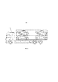
На Рис. 3 показаны две грузовые платформы (1 и 2), выполненные в соответствии с изобретением, первая из которых является частью грузовика (3), в то время как вторая является частью прицепа (4).In Fig. 3 shows two loading platforms (1 and 2) made in accordance with the invention, the first of which is part of the truck (3), while the second is part of the trailer (4).
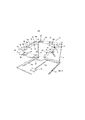
Платформа (1), Рис. 1 и 3, имеет две продольные балки (5 и 6), расположенные параллельно и на одной высоте, которые установлены на подъемном механизме, который, в данном случае, имеет две вертикальные подъемные стойки (7). Две наклонные плоские конструкции (8) установлены между каждыми двумя балками (5 и 6), расположенными на одной высоте.Platform (1), Fig. 1 and 3, has two longitudinal beams (5 and 6), located parallel and at the same height, which are mounted on a lifting mechanism, which, in this case, has two vertical lifting legs (7). Two inclined flat structures (8) are installed between each two beams (5 and 6), located at the same height.
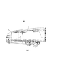
Платформа (2), Рис. 3, имеет две верхние продольные балки (5 и 6), расположенные на одной высоте, между которыми установлены две наклонные плоские конструкции (8), и две нижние продольные балки (5' и 6'), также расположенные на той же высоте, между которыми установлена одна наклонная плоская конструкция (8).Platform (2), Fig. 3, has two upper longitudinal beams (5 and 6), located at the same height, between which two inclined flat structures (8) are installed, and two lower longitudinal beams (5 'and 6'), also located at the same height, between which has one inclined flat structure (8).
Подъемные вертикальные стойки (7) расположены таким образом, что они совпадают с концами продольных балок (5 и 6) и имеют такую же высоту, что и грузовик или прицеп, частью которого они являются.The vertical lifting struts (7) are positioned so that they match the ends of the longitudinal beams (5 and 6) and are the same height as the truck or trailer of which they are a part.
Платформа может включать в себя, если необходимо, одну или несколько промежуточных вертикальных подъемных стоек (7'), Рис. 6. В случае наличия промежуточных вертикальных подъемных стоек (7') и во избежание потери чистой ширины для груза в грузовике, предусмотрена возможность, чтобы данные стойки не располагались в грузовике противоположно, а вместо этого находились не в противоположных положениях с обеих сторон, как это показано на Рис. 6. Как показано на Рис. 1 и 2, каждая наклонная плоская платформа (8) установлена между двумя балками (5 и 6) с помощью двух выровненных поперечных валов (9), также она связана с указанными балками посредством привода (10), например, гидравлического типа. Активация данного привода вызывает наклон наклонной плоской конструкции (8) до достижения требуемого положения в каждом случае.The platform can include, if necessary, one or more intermediate vertical lifting struts (7 '), Fig. 6. In the case of intermediate vertical lifting struts (7 ') and in order to avoid a loss of net width for the load in the truck, it is possible that these struts are not located opposite in the truck, but instead are not in opposite positions on both sides, as is shown in Fig. 6. As shown in Fig. 1 and 2, each inclined flat platform (8) is installed between two beams (5 and 6) by means of two aligned transverse shafts (9), and it is also connected to said beams by means of a drive (10), for example, of a hydraulic type. Activation of this actuator causes the inclined flat structure (8) to tilt until the required position is reached in each case.
На Рис. 3 в прицепе (4) можно увидеть, что привод (10), который фиксирует наклонную плоскую конструкцию (8), позволяет фиксировать указанный наклон путем вращения указанной конструкции (8) как по часовой стрелке, так и против часовой стрелки для того, чтобы приспособиться к разному типу грузов и разным габаритам автомобилей в каждом конкретном случае.In Fig. 3, in the trailer (4), it can be seen that the drive (10), which fixes the inclined flat structure (8), allows the indicated inclination to be fixed by rotating the indicated structure (8) both clockwise and counterclockwise in order to adapt to different types of cargo and different dimensions of vehicles in each specific case.
Подъемные вертикальные стойки (7) состоят, в изображенном примере, из вертикальных шпинделей, Рис. 1 и 2, где установлены резьбовые элементы (11). Вращение шпинделей стоек (7) вокруг своей оси приведет к тому, что резьбовые элементы (11) будут подниматься или опускаться. В платформе (2), Рис. 3, верхние продольные балки (5 и 6) соединены посредством, как минимум, четырех резьбовых элементов (11) со шпинделями стоек (7), и другие нижние продольные балки (5' и 6') также соединены посредством, как минимум, четырех других резьбовых элементов (11) со шпинделями другого независимого комплекта стоек (7''), являясь параллельными стойкам (7) верхней платформы.The vertical lifting legs (7), in the example shown, consist of vertical spindles, Fig. 1 and 2 where the threaded elements (11) are installed. Rotation of the spindles of the legs (7) around their axis will cause the threaded elements (11) to rise or fall. In the platform (2), Fig. 3, the upper longitudinal beams (5 and 6) are connected by means of at least four threaded elements (11) to the spindles of the posts (7), and the other lower longitudinal beams (5 'and 6') are also connected by means of at least four others threaded elements (11) with spindles of another independent set of legs (7 ''), being parallel to the legs (7) of the upper platform.
В качестве средств безопасности, между каждой наклонной плоской конструкцией (8) и продольными балками (5 и 6) может быть расположена дуга (12), Рис. 2, ограничивающая максимальный угол наклона указанных конструкций.As a safety feature, an arc (12) can be located between each inclined flat structure (8) and the longitudinal beams (5 and 6), Fig. 2, limiting the maximum angle of inclination of these structures.
Смещение резьбовых элементов (11), поддерживающих балки (5-6), расположенных на одной высоте, будет синхронизировано, например, посредством действия одного двигателя (13), Рис. 2 и 7, расположенного под транспортной платформой для того, чтобы не уменьшать грузоподъемность, Рис. 1. С помощью передаточных штанг (14) можно достичь механического сцепления, вызывающего одновременное вращение всех шпинделей вокруг своей оси.The displacement of the threaded elements (11) supporting the beams (5-6), located at the same height, will be synchronized, for example, by the action of one motor (13), Fig. 2 and 7 located under the transport platform in order not to reduce the carrying capacity, Fig. 1. With the help of the transfer rods (14), it is possible to achieve a mechanical clutch that causes the simultaneous rotation of all spindles around its axis.
Наклонные плоские конструкции (8), Рис. 2, состоят из рамы, выполненной в виде телескопической рамы, содержащей два U-образных обода (16), боковые ответвления которых (17) выровнены и соединены с помощью телескопического механизма, состоящего, например, из промежуточного трубчатого профиля (18), через который проходят выровненные боковые ответвления (17), а также привод, например, гидравлического типа. Трубчатый профиль (18) установлен на продольных балках (5-6) через вал (9), удерживающий трубчатый профиль (18) на его внешней поверхности, таким образом, ответвления (17) могут скользить вдоль указанного трубчатого профиля с помощью привода (19), например, гидравлического типа, с тем, чтобы осуществлять продольное смещение плоских конструкций относительно продольных балок (5 и 6). Обода (16) имеют полости (20) для установки колес транспортируемых автомобилей, при этом указанные полости могут включать в себя, как минимум, штангу (21) с регулируемым положением, Рис. 2, которая будет зафиксирована в требуемом положении, чтобы приспособиться под различные размеры колес разных автомобилей.Inclined flat structures (8), Fig. 2, consist of a frame made in the form of a telescopic frame containing two U-shaped rims (16), the lateral branches of which (17) are aligned and connected using a telescopic mechanism, consisting, for example, of an intermediate tubular profile (18), through which there are aligned side branches (17), as well as a drive, for example, of a hydraulic type. The tubular profile (18) is mounted on the longitudinal beams (5-6) through the shaft (9) holding the tubular profile (18) on its outer surface, so the branches (17) can slide along the specified tubular profile using the drive (19) , for example, of the hydraulic type, in order to carry out the longitudinal displacement of flat structures relative to the longitudinal beams (5 and 6). The rims (16) have cavities (20) for mounting the wheels of transported vehicles, while these cavities can include at least a bar (21) with an adjustable position, Fig. 2, which will be locked in the required position to accommodate different wheel sizes of different vehicles.
Боковые телескопические ответвления (17) будут приспосабливаться, вручную или автоматически, к расстоянию между осями поддерживаемого автомобиля. После того, как автомобиль в них помещен, он будет зафиксирован с помощью болта (22), Рис. 2, с целью фиксации телескопического движения боковых ответвлений (17).The side telescopic arms (17) will adjust, manually or automatically, to the distance between the axles of the vehicle being supported. After placing the car in them, it will be fixed with the bolt (22), Fig. 2, in order to fix the telescopic movement of the lateral branches (17).
Как только телескопическое движение боковых ответвлений (17) будет зафиксировано, задействуется привод (19), приводя в движение боковые ответвления (17), чтобы последние скользили вдоль трубчатого профиля (18), который прикреплен к продольным балкам (5 и 6) через вал (9), таким образом, платформа перемещается в грузовике в продольном направлении вперед или назад до упора, достигая длины привода (19). Наконец, с помощью привода (10) и дуги (12), Рис. 2, фиксируется угловое положение плоских конструкций.As soon as the telescopic movement of the side arms (17) is fixed, the drive (19) is activated, driving the side arms (17) so that the latter slide along the tubular profile (18), which is attached to the longitudinal beams (5 and 6) through the shaft ( 9), thus, the platform moves in the truck in the longitudinal direction forward or backward until it stops, reaching the length of the drive (19). Finally, by means of a drive (10) and an arc (12), Fig. 2, the angular position of flat structures is fixed.
Как показано на Рис. 2, продольные балки (5 и 6) имеют несколько отверстий (23), Рис. 2, с целью получения дополнительной регулировки продольного положения платформ (8). Данные отверстия (23) выровнены в обеих балках, а между ними двумя установлены выровненные поперечные валы (9), что позволяет переместить вал (9) платформ (8) вдоль продольных балок (5 и 6) в зависимости от размеров перевозимых автомобилей. Изменение отверстия (23) наклонной плоской конструкции (8) в данном случае должно быть выполнено вручную, когда платформы находятся у основания грузовика до процесса погрузки автомобиля.As shown in Fig. 2, the longitudinal beams (5 and 6) have several holes (23), Fig. 2, in order to obtain additional adjustment of the longitudinal position of the platforms (8). These holes (23) are aligned in both beams, and between the two there are aligned transverse shafts (9), which allows the shaft (9) of the platforms (8) to move along the longitudinal beams (5 and 6), depending on the dimensions of the transported vehicles. Changing the hole (23) of the inclined flat structure (8) in this case must be done manually, when the platforms are at the base of the truck before loading the car.
Для того чтобы автоматически выполнять это движение вдоль продольных балок (5 и 6), была предусмотрена каретка (25), оснащенная подшипниками, которая работает как средство смещения для вращающегося вала (9), как минимум, одной из наклонных конструкций. Вал (9) и конец привода (10) установлены на указанной каретке (25), как показано на Рис. 7. Данная каретка (25) с подшипниками будет смещаться вдоль продольных балок (5 и 6), будучи приводимой в действие приводом (26), который может быть приводом гидравлического типа; данная деталь более подробно показана на Рис. 7А. Конкретно, на Рис. 7А показана каретка (25), оснащенная несколькими подшипниками для обеспечения возможности перемещения каретки (25) и, следовательно, перемещения поперечного вала (9) в разных положениях вдоль продольной балки (5). В особо предпочтительном варианте исполнения поперечный вал (9) находится вблизи середины наклонной конструкции платформы, то есть, вдали от концов. Кроме того, блокирование движения каретки (25) может быть достигнуто с помощью закрепления болтами, как это показано на Рис. 7, или путем блокировки привода (26) в фиксированное положение.In order to automatically carry out this movement along the longitudinal beams (5 and 6), a carriage (25) equipped with bearings was provided, which acts as a means of displacement for the rotating shaft (9), at least one of the inclined structures. The shaft (9) and the end of the drive (10) are mounted on the indicated carriage (25) as shown in Fig. 7. This carriage (25) with bearings will move along the longitudinal beams (5 and 6), being driven by an actuator (26), which may be of a hydraulic type; this detail is shown in more detail in Fig. 7A. Specifically, in Fig. 7A shows a carriage (25) equipped with multiple bearings to allow the carriage (25) to move and therefore move the transverse shaft (9) in different positions along the longitudinal beam (5). In a particularly preferred embodiment, the transverse shaft (9) is located near the middle of the inclined platform structure, that is, far from the ends. Alternatively, blocking the movement of the carriage (25) can be achieved by bolting, as shown in Fig. 7, or by locking the actuator (26) to a fixed position.
Пространство, разграниченное между каждыми двумя U-образными ободками (16) наклонных плоских конструкций, позволит максимально сблизить перевозимые автомобили, что позволяет приблизить крышу автомобиля к нижней части автомобиля, находящегося сверху, тем самым уменьшая высоту при максимальной уклоне и перевозке двух рядов автомобилей в грузовике, как это изображено в варианте исполнения на Рис. 4.The space delimited between each two U-shaped rims (16) of the inclined flat structures will allow the transported vehicles to be brought closer together, which allows the roof of the vehicle to be brought closer to the lower part of the vehicle on top, thereby reducing the height at the maximum incline and transporting two rows of vehicles in a truck as shown in the embodiment in Fig. 4.
Когда нет необходимости регулировать или изменять длину наклонных плоских конструкций (8), указанные конструкции могут представлять собой фиксированную прямоугольную раму.When there is no need to adjust or change the length of the inclined flat structures (8), these structures can be a fixed rectangular frame.
Через платформу, указанную в изобретении, для ее использования при перевозке грузов, перемещаются продольные балки (5 и 6) и наклонные плоские конструкции (8) до достижения своего наивысшего положения, располагаясь в полностью горизонтальном положении, чтобы занимать минимальное пространство, при этом платформа становится свободной для осуществления погрузки на нее задним или боковым способом, как показано на Рис. 5. Кроме того, продольные балки (5 и 6) и наклонные плоские конструкции (8) могут быть смещены вверх к поверхности платформы, и, с помощью покрытий можно создать сплошную поверхность для погрузки.Through the platform specified in the invention, for its use in the transport of goods, the longitudinal beams (5 and 6) and inclined flat structures (8) move until reaching their highest position, being located in a completely horizontal position in order to take up the minimum space, while the platform becomes free for rearward or side loading on it, as shown in Fig. 5. In addition, the longitudinal beams (5 and 6) and inclined flat structures (8) can be displaced upward towards the platform surface and, with the help of covers, a continuous loading surface can be created.
Когда платформа используется для перевозки автомобилей, в тот момент, когда они погружены, на представленной платформе создаются плоские конструкции на полу путем выставления на задней части платформы наклонных скатов, что позволяет поднимать автомобили.When the platform is used to transport vehicles, at the moment when they are loaded, flat structures on the floor are created on the presented platform by placing inclined slopes on the back of the platform, which allows the vehicles to be lifted.
Длина каждой плоской конструкции регулируется в соответствии с расстоянием между осями автомобиля, и в момент регулировки указанной длины предусматривается использование болтов (22), Рис. 22, позволяющих зафиксировать выбранную длину, затем выполняется погрузка автомобилей, после чего колеса закрепляются стропами.The length of each flat structure is adjusted in accordance with the distance between the axles of the vehicle, and at the time of adjusting the specified length, the use of bolts (22), Fig. 22, allowing to fix the selected length, then the vehicles are loaded, after which the wheels are secured with slings.
Затем автомобили, погруженные на конструкции верхнего уровня, поднимаются, чтобы можно было погрузить автомобили на нижний ярус. Чтобы поднять автомобили верхнего яруса таким образом, чтобы они не касались крыши, крыши должны быть оснащены независимыми телескопическими механизмами, которые позволяют выполнить указанное действие. После того, как автомобили в нижней области расположены и зафиксированы стропами, выполняется регулировка высоты верхнего уровня, а также угла наклона плоских конструкций путем задействования привода (10) и регулирования продольного положения при помощи привода (19), также, выбранные положения фиксируются с помощью штифтов (24) и дуги (12), Рис. 2.The vehicles loaded on the upper level structure are then lifted so that the vehicles can be loaded onto the lower level. To raise the top-tier vehicles so that they do not touch the roof, the roofs must be equipped with independent telescopic mechanisms that allow this action to be carried out. After the cars in the lower area are located and fixed with slings, the height of the upper level is adjusted, as well as the angle of inclination of flat structures by activating the drive (10) and adjusting the longitudinal position using the drive (19), also, the selected positions are fixed by means of pins (24) and arcs (12), Fig. 2.
При разгрузке автомобилей данные операции выполняются в обратном порядке.When unloading vehicles, these operations are performed in reverse order.
Для максимального использования пространства задействуются как крыша, так и передние и задние двери грузовиков, прицепов или съемных кузовов, чтобы в конечном итоге их можно было сделать из брезента, который можно свернуть для того, чтобы перевозка могла осуществляться, когда одна из данных частей открыта и, таким образом, это дает возможность поместить автомобили в конец транспортного средства с целью максимизации использования, как чистой высоты, так и длины.To maximize space utilization, both the roof and the front and rear doors of trucks, trailers or swap bodies are utilized so that they can ultimately be made of tarpaulin that can be rolled up so that transport can take place when one of these parts is open and thus, it makes it possible to place cars at the end of the vehicle in order to maximize the use of both net height and length.
Claims (12)
Applications Claiming Priority (4)
| Application Number | Priority Date | Filing Date | Title |
|---|---|---|---|
| ES201630854A ES2647974B1 (en) | 2016-06-23 | 2016-06-23 | TRANSPORT PLATFORM |
| ESP201630854 | 2016-06-23 | ||
| ES?201630854 | 2016-06-23 | ||
| PCT/ES2017/070447 WO2017220838A1 (en) | 2016-06-23 | 2017-06-20 | Transport platform |
Publications (3)
| Publication Number | Publication Date |
|---|---|
| RU2018144423A3 RU2018144423A3 (en) | 2020-07-23 |
| RU2018144423A RU2018144423A (en) | 2020-07-23 |
| RU2741659C2 true RU2741659C2 (en) | 2021-01-28 |
Family
ID=59569346
Family Applications (1)
| Application Number | Title | Priority Date | Filing Date |
|---|---|---|---|
| RU2018144423A RU2741659C2 (en) | 2016-06-23 | 2017-06-20 | Transport platform |
Country Status (14)
| Country | Link |
|---|---|
| US (1) | US10752151B2 (en) |
| EP (1) | EP3476652B1 (en) |
| JP (1) | JP2019521042A (en) |
| KR (1) | KR20190021254A (en) |
| CN (1) | CN109476252A (en) |
| BR (1) | BR112018076692A2 (en) |
| CA (1) | CA3028093A1 (en) |
| ES (2) | ES2647974B1 (en) |
| MA (1) | MA45458B1 (en) |
| MX (1) | MX2018016402A (en) |
| PT (1) | PT3476652T (en) |
| RU (1) | RU2741659C2 (en) |
| SI (1) | SI3476652T1 (en) |
| WO (1) | WO2017220838A1 (en) |
Families Citing this family (6)
| Publication number | Priority date | Publication date | Assignee | Title |
|---|---|---|---|---|
| US10801169B2 (en) | 2015-06-29 | 2020-10-13 | Royal Truck & Equipment, Inc | Truck safety modules for assisting workpersons to place and retrieve traffic delineators |
| US11008717B2 (en) * | 2015-06-29 | 2021-05-18 | Royal Truck & Equipment, Inc. | Safety truck attachments, and methods of safety truck use |
| US10556545B2 (en) * | 2015-06-29 | 2020-02-11 | Royal Truck & Equipment, Inc. | Over-cab rack for traffic delineators |
| CN113320582A (en) * | 2021-05-27 | 2021-08-31 | 江苏西玛环境科技有限公司 | Material conveying device for waste incineration plant |
| CN113276752B (en) * | 2021-06-24 | 2022-08-19 | 枣庄市东博矿山机械设备有限公司 | Vehicle transportation device based on lifting of transportation load capacity of industrial complete machine |
| CN113184063B (en) * | 2021-06-24 | 2023-01-13 | 陶泓羽 | Vehicle transportation method based on improvement of transportation cargo capacity of industrial complete machine |
Citations (8)
| Publication number | Priority date | Publication date | Assignee | Title |
|---|---|---|---|---|
| EP0208980B1 (en) * | 1984-02-03 | 1990-04-04 | Transportation Manufacturing Corporation (a Delaware corporation) | Apparatus for supporting vehicles and the like |
| US5080541A (en) * | 1988-08-05 | 1992-01-14 | Lohr Industrie, S.A. | Articulated car carrier convoy with individual carrying platforms capable of compound movements |
| EP0595051A1 (en) * | 1992-10-29 | 1994-05-04 | ROLFO S.p.A. | A motor-vehicle transporter |
| WO1998009889A1 (en) * | 1996-09-07 | 1998-03-12 | Clive Smith Martin | Multi-deck container |
| EP0718149B1 (en) * | 1994-12-23 | 1999-05-06 | ROLFO S.p.A. | Combination including a vehicle with superposed platforms for transporting motor vehicles |
| WO2000069677A1 (en) * | 1999-05-17 | 2000-11-23 | Clive Smith Martin | (vehicle) load mounting in container |
| US20070020059A1 (en) * | 2005-07-20 | 2007-01-25 | Permar Oy | Transport unit, a transport system and a method |
| RU76608U1 (en) * | 2008-05-28 | 2008-09-27 | Общество с ограниченной ответственностью "АвтоСпецТехника-Канаш" | SEMITRAILER FOR CAR TRANSPORTATION |
Family Cites Families (36)
| Publication number | Priority date | Publication date | Assignee | Title |
|---|---|---|---|---|
| US1824370A (en) * | 1928-09-01 | 1931-09-22 | Fruehauf Trailer Co | Automobile carrying vehicle |
| US1978287A (en) * | 1932-03-09 | 1934-10-23 | New York Central Railroad Co | Vehicle loading means for box cars |
| US2640562A (en) * | 1947-03-12 | 1953-06-02 | Villars Julio | Lifting appliance for vehicles |
| GB1006496A (en) * | 1963-08-19 | 1965-10-06 | John Swartzwelder | Adjustable motor vehicle transport |
| US3104127A (en) * | 1962-06-14 | 1963-09-17 | Swartzwelder John | Adjustable motor vehicle transport |
| FR1373916A (en) * | 1963-08-19 | 1964-10-02 | Adjustable automobile transport machine | |
| GB1111434A (en) * | 1965-10-06 | 1968-04-24 | Denis Howard | Improvements relating to road vehicle transporters |
| FR2573014B1 (en) * | 1984-11-15 | 1988-04-15 | Lohr Sa | CAR VEHICLE WITH INDIVIDUAL CROSS-CARRIER STRUCTURES SPECIFIC TO EACH WHEEL TRAIN |
| CA1234373A (en) | 1986-02-10 | 1988-03-22 | Atlantis Projects Inc. | Transportation van having load elevating platform located therein |
| US5105951A (en) * | 1986-12-18 | 1992-04-21 | G & G Intellectual Properties, Inc. | Frame for transporting wheeled vehicles |
| US5040938A (en) * | 1986-12-18 | 1991-08-20 | G & G Intellectual Properties, Inc. | Loading and transporting system |
| US4992013A (en) | 1988-10-21 | 1991-02-12 | Autohaul Industries, Inc. | Combination freight and vehicle carrying trailer |
| FR2651732B1 (en) * | 1989-09-12 | 1994-10-21 | Lohr Ind | UPPER CAR CARRIER UNIT FOR ROAD VEHICLE. |
| US5281075A (en) * | 1991-11-15 | 1994-01-25 | Tatman Darrell J | Apparatus for transporting recreational type vehicles |
| US5297908A (en) | 1993-02-04 | 1994-03-29 | J. B. Hunt Transport Services, Inc. | Apparatus and method for transporting automobiles in an enclosed semi-trailer |
| US5286149A (en) * | 1993-02-16 | 1994-02-15 | Seay Michael W | Apparatus for supporting a vehicle inside a cargo container |
| US5454672A (en) * | 1993-03-17 | 1995-10-03 | G & G Intellectual Properties, Inc. | Adjustable load-carrying frame for fully utilizing transport enclosure space |
| US5344266A (en) * | 1993-04-16 | 1994-09-06 | Kolb Peter W | Fully adjustable storage device for loading and transporting vehicles in containers |
| US5567111A (en) * | 1993-12-28 | 1996-10-22 | G & G Intellectual Properties, Inc. | Method for handling and transporting wheeled vehicles |
| US5890855A (en) * | 1994-04-15 | 1999-04-06 | Claps; William R. | Method and apparatus for transporting cars |
| IT1283047B1 (en) * | 1996-05-21 | 1998-04-07 | Luigi Oglio | CONTAINER WITH INTERNAL VERTICAL LIFT, PARTICULARLY FOR THE SHIPPING OF CARS |
| FR2749630B1 (en) * | 1996-06-07 | 1998-10-09 | Lohr Ind | DEVICE FOR MANEUVERING A CARRIER STRUCTURE FROM A TORQUE OF SCREWS EACH CARRYING A TRANSLATION NUT |
| NL1007191C2 (en) * | 1997-10-01 | 1999-04-07 | Groenewold S Carrosseriefabrie | Double-deck car transporter. |
| WO2002028748A1 (en) * | 2000-10-03 | 2002-04-11 | Clive Smith Martin | Vehicle support frame |
| CN2481666Y (en) * | 2001-05-29 | 2002-03-13 | 扬州通华专用车股份有限公司 | Sedan transporting container |
| US9380881B2 (en) * | 2003-07-31 | 2016-07-05 | Lippert Components, Inc. | Strap bed lift |
| US6983979B2 (en) * | 2003-07-31 | 2006-01-10 | Happijac Company | System for moving beds |
| WO2005035397A1 (en) | 2003-10-10 | 2005-04-21 | Rokko Engineering Co., Ltd. | Rack for freight |
| JP2007131332A (en) * | 2005-11-10 | 2007-05-31 | Nippon Riku-Un Sangyo Co Ltd | Tank container |
| CN201040502Y (en) | 2007-01-25 | 2008-03-26 | 威廉·波路可 | Multipurpose trailer for transporting automobile |
| CN201068303Y (en) | 2007-06-01 | 2008-06-04 | 南通中集特种运输设备制造有限公司 | Vehicle transporting frame capable of being placed in container and container comprising the same |
| CN101318586B (en) | 2007-06-04 | 2010-07-21 | 南通中集特种运输设备制造有限公司 | Dual-purpose container for vehicle and goods |
| CN201082687Y (en) * | 2007-06-25 | 2008-07-09 | 重庆耐德山花特种车有限责任公司 | Transport vehicle for conveying vehicles |
| JP5390966B2 (en) * | 2009-07-07 | 2014-01-15 | 株式会社ロッコーエンジニアリング | Cargo rack |
| CN203497448U (en) | 2013-10-11 | 2014-03-26 | 东方国际集装箱(广州)有限公司 | Automobile transportation container |
| FR3024084B1 (en) * | 2014-07-28 | 2018-01-05 | Lohr Electromecanique | CARRIER PALLET, INDIVIDUAL AND UNIVERSAL, FOR VEHICLE CAR RACK |
-
2016
- 2016-06-23 ES ES201630854A patent/ES2647974B1/en active Active
-
2017
- 2017-06-20 JP JP2019520496A patent/JP2019521042A/en active Pending
- 2017-06-20 KR KR1020187037311A patent/KR20190021254A/en not_active Application Discontinuation
- 2017-06-20 CN CN201780038628.2A patent/CN109476252A/en active Pending
- 2017-06-20 EP EP17749743.5A patent/EP3476652B1/en active Active
- 2017-06-20 ES ES17749743T patent/ES2938211T3/en active Active
- 2017-06-20 MX MX2018016402A patent/MX2018016402A/en unknown
- 2017-06-20 US US16/309,329 patent/US10752151B2/en active Active
- 2017-06-20 PT PT177497435T patent/PT3476652T/en unknown
- 2017-06-20 CA CA3028093A patent/CA3028093A1/en active Pending
- 2017-06-20 BR BR112018076692-5A patent/BR112018076692A2/en unknown
- 2017-06-20 SI SI201731303T patent/SI3476652T1/en unknown
- 2017-06-20 MA MA45458A patent/MA45458B1/en unknown
- 2017-06-20 WO PCT/ES2017/070447 patent/WO2017220838A1/en unknown
- 2017-06-20 RU RU2018144423A patent/RU2741659C2/en active
Patent Citations (8)
| Publication number | Priority date | Publication date | Assignee | Title |
|---|---|---|---|---|
| EP0208980B1 (en) * | 1984-02-03 | 1990-04-04 | Transportation Manufacturing Corporation (a Delaware corporation) | Apparatus for supporting vehicles and the like |
| US5080541A (en) * | 1988-08-05 | 1992-01-14 | Lohr Industrie, S.A. | Articulated car carrier convoy with individual carrying platforms capable of compound movements |
| EP0595051A1 (en) * | 1992-10-29 | 1994-05-04 | ROLFO S.p.A. | A motor-vehicle transporter |
| EP0718149B1 (en) * | 1994-12-23 | 1999-05-06 | ROLFO S.p.A. | Combination including a vehicle with superposed platforms for transporting motor vehicles |
| WO1998009889A1 (en) * | 1996-09-07 | 1998-03-12 | Clive Smith Martin | Multi-deck container |
| WO2000069677A1 (en) * | 1999-05-17 | 2000-11-23 | Clive Smith Martin | (vehicle) load mounting in container |
| US20070020059A1 (en) * | 2005-07-20 | 2007-01-25 | Permar Oy | Transport unit, a transport system and a method |
| RU76608U1 (en) * | 2008-05-28 | 2008-09-27 | Общество с ограниченной ответственностью "АвтоСпецТехника-Канаш" | SEMITRAILER FOR CAR TRANSPORTATION |
Also Published As
| Publication number | Publication date |
|---|---|
| MX2018016402A (en) | 2019-08-12 |
| ES2647974A1 (en) | 2017-12-27 |
| WO2017220838A1 (en) | 2017-12-28 |
| MA45458A (en) | 2021-04-14 |
| SI3476652T1 (en) | 2023-03-31 |
| EP3476652A1 (en) | 2019-05-01 |
| PT3476652T (en) | 2023-02-13 |
| US10752151B2 (en) | 2020-08-25 |
| KR20190021254A (en) | 2019-03-05 |
| US20190308547A1 (en) | 2019-10-10 |
| RU2018144423A3 (en) | 2020-07-23 |
| MA45458B1 (en) | 2023-03-31 |
| CN109476252A (en) | 2019-03-15 |
| EP3476652B1 (en) | 2022-11-09 |
| ES2938211T3 (en) | 2023-04-05 |
| CA3028093A1 (en) | 2017-12-28 |
| RU2018144423A (en) | 2020-07-23 |
| ES2647974B1 (en) | 2018-10-05 |
| JP2019521042A (en) | 2019-07-25 |
| BR112018076692A2 (en) | 2019-04-02 |
Similar Documents
| Publication | Publication Date | Title |
|---|---|---|
| RU2741659C2 (en) | Transport platform | |
| AU2018271285B2 (en) | Transport trailer | |
| US5567111A (en) | Method for handling and transporting wheeled vehicles | |
| JP5728079B2 (en) | Convertible trailer | |
| US20040013504A1 (en) | Straddle carrier | |
| AU2015295135A1 (en) | Individual, universal, removable, load-bearing pallet for car-carrying vehicle | |
| US5803698A (en) | Bodied vehicle | |
| US5332345A (en) | Vehicle carrier | |
| US11660996B2 (en) | Bridge apparatus and system for vehicle transport | |
| FI61435B (en) | FOERFARANDE OCH ANORDNING FOER HANTERING OCH TRANSPORTERING I SYNNERHET MELLAN ETT RO / RO-FARTYG OCH EN TERMINAL AV ETT ENHETSLASS BESTAOENDE AV EN ELLER FLERA CONTAINRAR ELLER DYLIKA | |
| US5067869A (en) | Automobile transportation apparatus | |
| WO1985003481A1 (en) | Self loading system | |
| RU2725847C1 (en) | Automatic evacuator | |
| EP2116419B1 (en) | Crane vehicle | |
| CN111727134B (en) | Chassis assembly for a transport vehicle | |
| AU2004213060B2 (en) | Transport module | |
| EP1486390A2 (en) | Automated conveyor line system for a motor vehicle | |
| AU580985B2 (en) | Self loading system | |
| WO2004074136A1 (en) | Transport module | |
| SE469716B (en) | VEHICLE FOR TRANSPORT OF CARGO CONTAINERS |