RU2732111C2 - Bag for sterile product solution - Google Patents
Bag for sterile product solution Download PDFInfo
- Publication number
- RU2732111C2 RU2732111C2 RU2018127841A RU2018127841A RU2732111C2 RU 2732111 C2 RU2732111 C2 RU 2732111C2 RU 2018127841 A RU2018127841 A RU 2018127841A RU 2018127841 A RU2018127841 A RU 2018127841A RU 2732111 C2 RU2732111 C2 RU 2732111C2
- Authority
- RU
- Russia
- Prior art keywords
- filter
- bag
- filling
- solution
- rod
- Prior art date
Links
- 239000012528 membrane Substances 0.000 claims abstract description 131
- 239000000243 solution Substances 0.000 claims abstract description 111
- 238000011049 filling Methods 0.000 claims abstract description 72
- 239000011148 porous material Substances 0.000 claims abstract description 36
- 239000012530 fluid Substances 0.000 claims abstract description 29
- 239000008174 sterile solution Substances 0.000 claims abstract description 27
- 238000004891 communication Methods 0.000 claims abstract description 13
- 238000001914 filtration Methods 0.000 claims abstract description 10
- 238000007789 sealing Methods 0.000 claims description 37
- 239000012510 hollow fiber Substances 0.000 claims description 34
- 239000000463 material Substances 0.000 claims description 21
- 229920000098 polyolefin Polymers 0.000 claims description 10
- 238000000502 dialysis Methods 0.000 claims description 9
- 230000036512 infertility Effects 0.000 claims description 7
- 239000007924 injection Substances 0.000 claims description 7
- 238000002347 injection Methods 0.000 claims description 7
- 229920000642 polymer Polymers 0.000 claims description 7
- 239000004695 Polyether sulfone Substances 0.000 claims description 6
- 229920003229 poly(methyl methacrylate) Polymers 0.000 claims description 6
- 229920002492 poly(sulfone) Polymers 0.000 claims description 6
- 239000004417 polycarbonate Substances 0.000 claims description 6
- 229920000515 polycarbonate Polymers 0.000 claims description 6
- 229920006393 polyether sulfone Polymers 0.000 claims description 6
- 239000004926 polymethyl methacrylate Substances 0.000 claims description 6
- 239000002033 PVDF binder Substances 0.000 claims description 5
- 239000004793 Polystyrene Substances 0.000 claims description 5
- 150000001768 cations Chemical class 0.000 claims description 5
- 229920001577 copolymer Polymers 0.000 claims description 5
- 229920002239 polyacrylonitrile Polymers 0.000 claims description 5
- 229920000139 polyethylene terephthalate Polymers 0.000 claims description 5
- 229920000193 polymethacrylate Polymers 0.000 claims description 5
- 229920002981 polyvinylidene fluoride Polymers 0.000 claims description 5
- 229920002223 polystyrene Polymers 0.000 claims description 4
- 229920000915 polyvinyl chloride Polymers 0.000 claims description 4
- 230000001681 protective effect Effects 0.000 claims description 4
- 229920005573 silicon-containing polymer Polymers 0.000 claims description 4
- 244000005700 microbiome Species 0.000 abstract description 3
- 239000002245 particle Substances 0.000 abstract description 2
- 239000007787 solid Substances 0.000 abstract description 2
- 239000000126 substance Substances 0.000 abstract description 2
- 238000003466 welding Methods 0.000 description 27
- 238000012360 testing method Methods 0.000 description 21
- 230000001954 sterilising effect Effects 0.000 description 16
- 239000003186 pharmaceutical solution Substances 0.000 description 14
- 238000004659 sterilization and disinfection Methods 0.000 description 13
- 238000000034 method Methods 0.000 description 12
- 239000007788 liquid Substances 0.000 description 10
- 239000000853 adhesive Substances 0.000 description 9
- 238000004026 adhesive bonding Methods 0.000 description 9
- 230000001070 adhesive effect Effects 0.000 description 9
- 239000000835 fiber Substances 0.000 description 9
- 239000003522 acrylic cement Substances 0.000 description 8
- JHIVVAPYMSGYDF-UHFFFAOYSA-N cyclohexanone Chemical compound O=C1CCCCC1 JHIVVAPYMSGYDF-UHFFFAOYSA-N 0.000 description 8
- 239000004593 Epoxy Substances 0.000 description 7
- 238000004519 manufacturing process Methods 0.000 description 7
- 238000011109 contamination Methods 0.000 description 5
- 238000013461 design Methods 0.000 description 5
- 239000003814 drug Substances 0.000 description 4
- 229940079593 drug Drugs 0.000 description 4
- 239000003822 epoxy resin Substances 0.000 description 4
- 239000002184 metal Substances 0.000 description 4
- 239000000203 mixture Substances 0.000 description 4
- 229920000647 polyepoxide Polymers 0.000 description 4
- 229920005749 polyurethane resin Polymers 0.000 description 4
- 230000005855 radiation Effects 0.000 description 4
- 229920005989 resin Polymers 0.000 description 4
- 239000011347 resin Substances 0.000 description 4
- 239000002904 solvent Substances 0.000 description 4
- NIXOWILDQLNWCW-UHFFFAOYSA-N acrylic acid group Chemical group C(C=C)(=O)O NIXOWILDQLNWCW-UHFFFAOYSA-N 0.000 description 3
- 230000015556 catabolic process Effects 0.000 description 3
- 239000000356 contaminant Substances 0.000 description 3
- 238000005520 cutting process Methods 0.000 description 3
- 238000006731 degradation reaction Methods 0.000 description 3
- 238000009792 diffusion process Methods 0.000 description 3
- 238000005429 filling process Methods 0.000 description 3
- 238000009472 formulation Methods 0.000 description 3
- 239000003292 glue Substances 0.000 description 3
- XLYOFNOQVPJJNP-UHFFFAOYSA-N water Substances O XLYOFNOQVPJJNP-UHFFFAOYSA-N 0.000 description 3
- 230000001010 compromised effect Effects 0.000 description 2
- 238000005516 engineering process Methods 0.000 description 2
- 238000001125 extrusion Methods 0.000 description 2
- 239000013618 particulate matter Substances 0.000 description 2
- 229920001169 thermoplastic Polymers 0.000 description 2
- 229920005992 thermoplastic resin Polymers 0.000 description 2
- 238000009736 wetting Methods 0.000 description 2
- 238000010146 3D printing Methods 0.000 description 1
- 238000012371 Aseptic Filling Methods 0.000 description 1
- 229920002873 Polyethylenimine Polymers 0.000 description 1
- FAPWRFPIFSIZLT-UHFFFAOYSA-M Sodium chloride Chemical compound [Na+].[Cl-] FAPWRFPIFSIZLT-UHFFFAOYSA-M 0.000 description 1
- 238000003848 UV Light-Curing Methods 0.000 description 1
- 239000000654 additive Substances 0.000 description 1
- 238000013459 approach Methods 0.000 description 1
- 230000000712 assembly Effects 0.000 description 1
- 238000000429 assembly Methods 0.000 description 1
- 230000015572 biosynthetic process Effects 0.000 description 1
- 238000005229 chemical vapour deposition Methods 0.000 description 1
- 208000020832 chronic kidney disease Diseases 0.000 description 1
- 230000001427 coherent effect Effects 0.000 description 1
- 230000006866 deterioration Effects 0.000 description 1
- 238000010894 electron beam technology Methods 0.000 description 1
- 208000028208 end stage renal disease Diseases 0.000 description 1
- 201000000523 end stage renal failure Diseases 0.000 description 1
- 230000007613 environmental effect Effects 0.000 description 1
- 238000012061 filter integrity test Methods 0.000 description 1
- 125000000524 functional group Chemical group 0.000 description 1
- 238000010438 heat treatment Methods 0.000 description 1
- 238000003780 insertion Methods 0.000 description 1
- 230000037431 insertion Effects 0.000 description 1
- 238000011016 integrity testing Methods 0.000 description 1
- 230000013011 mating Effects 0.000 description 1
- 230000000813 microbial effect Effects 0.000 description 1
- 238000012544 monitoring process Methods 0.000 description 1
- 229920001558 organosilicon polymer Polymers 0.000 description 1
- 238000009928 pasteurization Methods 0.000 description 1
- 230000035515 penetration Effects 0.000 description 1
- 229920000728 polyester Polymers 0.000 description 1
- 239000001267 polyvinylpyrrolidone Substances 0.000 description 1
- 229920000036 polyvinylpyrrolidone Polymers 0.000 description 1
- 235000013855 polyvinylpyrrolidone Nutrition 0.000 description 1
- 238000002459 porosimetry Methods 0.000 description 1
- 125000001453 quaternary ammonium group Chemical group 0.000 description 1
- 238000000926 separation method Methods 0.000 description 1
- 239000011780 sodium chloride Substances 0.000 description 1
- 238000007655 standard test method Methods 0.000 description 1
- 239000008223 sterile water Substances 0.000 description 1
- 238000003860 storage Methods 0.000 description 1
- 230000007847 structural defect Effects 0.000 description 1
- 239000000725 suspension Substances 0.000 description 1
- 238000010998 test method Methods 0.000 description 1
Images


Classifications
-
- A—HUMAN NECESSITIES
- A61—MEDICAL OR VETERINARY SCIENCE; HYGIENE
- A61J—CONTAINERS SPECIALLY ADAPTED FOR MEDICAL OR PHARMACEUTICAL PURPOSES; DEVICES OR METHODS SPECIALLY ADAPTED FOR BRINGING PHARMACEUTICAL PRODUCTS INTO PARTICULAR PHYSICAL OR ADMINISTERING FORMS; DEVICES FOR ADMINISTERING FOOD OR MEDICINES ORALLY; BABY COMFORTERS; DEVICES FOR RECEIVING SPITTLE
- A61J1/00—Containers specially adapted for medical or pharmaceutical purposes
- A61J1/14—Details; Accessories therefor
- A61J1/1443—Containers with means for dispensing liquid medicaments in a filtered or sterile way, e.g. with bacterial filters
- A61J1/1456—Containers with means for dispensing liquid medicaments in a filtered or sterile way, e.g. with bacterial filters using liquid filters
-
- A—HUMAN NECESSITIES
- A61—MEDICAL OR VETERINARY SCIENCE; HYGIENE
- A61J—CONTAINERS SPECIALLY ADAPTED FOR MEDICAL OR PHARMACEUTICAL PURPOSES; DEVICES OR METHODS SPECIALLY ADAPTED FOR BRINGING PHARMACEUTICAL PRODUCTS INTO PARTICULAR PHYSICAL OR ADMINISTERING FORMS; DEVICES FOR ADMINISTERING FOOD OR MEDICINES ORALLY; BABY COMFORTERS; DEVICES FOR RECEIVING SPITTLE
- A61J1/00—Containers specially adapted for medical or pharmaceutical purposes
- A61J1/14—Details; Accessories therefor
-
- A—HUMAN NECESSITIES
- A61—MEDICAL OR VETERINARY SCIENCE; HYGIENE
- A61J—CONTAINERS SPECIALLY ADAPTED FOR MEDICAL OR PHARMACEUTICAL PURPOSES; DEVICES OR METHODS SPECIALLY ADAPTED FOR BRINGING PHARMACEUTICAL PRODUCTS INTO PARTICULAR PHYSICAL OR ADMINISTERING FORMS; DEVICES FOR ADMINISTERING FOOD OR MEDICINES ORALLY; BABY COMFORTERS; DEVICES FOR RECEIVING SPITTLE
- A61J1/00—Containers specially adapted for medical or pharmaceutical purposes
- A61J1/05—Containers specially adapted for medical or pharmaceutical purposes for collecting, storing or administering blood, plasma or medical fluids ; Infusion or perfusion containers
- A61J1/10—Bag-type containers
-
- A—HUMAN NECESSITIES
- A61—MEDICAL OR VETERINARY SCIENCE; HYGIENE
- A61J—CONTAINERS SPECIALLY ADAPTED FOR MEDICAL OR PHARMACEUTICAL PURPOSES; DEVICES OR METHODS SPECIALLY ADAPTED FOR BRINGING PHARMACEUTICAL PRODUCTS INTO PARTICULAR PHYSICAL OR ADMINISTERING FORMS; DEVICES FOR ADMINISTERING FOOD OR MEDICINES ORALLY; BABY COMFORTERS; DEVICES FOR RECEIVING SPITTLE
- A61J1/00—Containers specially adapted for medical or pharmaceutical purposes
- A61J1/14—Details; Accessories therefor
- A61J1/1406—Septums, pierceable membranes
-
- A—HUMAN NECESSITIES
- A61—MEDICAL OR VETERINARY SCIENCE; HYGIENE
- A61J—CONTAINERS SPECIALLY ADAPTED FOR MEDICAL OR PHARMACEUTICAL PURPOSES; DEVICES OR METHODS SPECIALLY ADAPTED FOR BRINGING PHARMACEUTICAL PRODUCTS INTO PARTICULAR PHYSICAL OR ADMINISTERING FORMS; DEVICES FOR ADMINISTERING FOOD OR MEDICINES ORALLY; BABY COMFORTERS; DEVICES FOR RECEIVING SPITTLE
- A61J1/00—Containers specially adapted for medical or pharmaceutical purposes
- A61J1/14—Details; Accessories therefor
- A61J1/1412—Containers with closing means, e.g. caps
-
- A—HUMAN NECESSITIES
- A61—MEDICAL OR VETERINARY SCIENCE; HYGIENE
- A61M—DEVICES FOR INTRODUCING MEDIA INTO, OR ONTO, THE BODY; DEVICES FOR TRANSDUCING BODY MEDIA OR FOR TAKING MEDIA FROM THE BODY; DEVICES FOR PRODUCING OR ENDING SLEEP OR STUPOR
- A61M1/00—Suction or pumping devices for medical purposes; Devices for carrying-off, for treatment of, or for carrying-over, body-liquids; Drainage systems
- A61M1/02—Blood transfusion apparatus
- A61M1/0209—Multiple bag systems for separating or storing blood components
- A61M1/0218—Multiple bag systems for separating or storing blood components with filters
-
- A—HUMAN NECESSITIES
- A61—MEDICAL OR VETERINARY SCIENCE; HYGIENE
- A61M—DEVICES FOR INTRODUCING MEDIA INTO, OR ONTO, THE BODY; DEVICES FOR TRANSDUCING BODY MEDIA OR FOR TAKING MEDIA FROM THE BODY; DEVICES FOR PRODUCING OR ENDING SLEEP OR STUPOR
- A61M1/00—Suction or pumping devices for medical purposes; Devices for carrying-off, for treatment of, or for carrying-over, body-liquids; Drainage systems
- A61M1/14—Dialysis systems; Artificial kidneys; Blood oxygenators ; Reciprocating systems for treatment of body fluids, e.g. single needle systems for hemofiltration or pheresis
- A61M1/28—Peritoneal dialysis ; Other peritoneal treatment, e.g. oxygenation
-
- A—HUMAN NECESSITIES
- A61—MEDICAL OR VETERINARY SCIENCE; HYGIENE
- A61M—DEVICES FOR INTRODUCING MEDIA INTO, OR ONTO, THE BODY; DEVICES FOR TRANSDUCING BODY MEDIA OR FOR TAKING MEDIA FROM THE BODY; DEVICES FOR PRODUCING OR ENDING SLEEP OR STUPOR
- A61M39/00—Tubes, tube connectors, tube couplings, valves, access sites or the like, specially adapted for medical use
- A61M39/10—Tube connectors; Tube couplings
- A61M39/105—Multi-channel connectors or couplings, e.g. for connecting multi-lumen tubes
-
- B—PERFORMING OPERATIONS; TRANSPORTING
- B01—PHYSICAL OR CHEMICAL PROCESSES OR APPARATUS IN GENERAL
- B01D—SEPARATION
- B01D61/00—Processes of separation using semi-permeable membranes, e.g. dialysis, osmosis or ultrafiltration; Apparatus, accessories or auxiliary operations specially adapted therefor
- B01D61/24—Dialysis ; Membrane extraction
- B01D61/243—Dialysis
-
- B—PERFORMING OPERATIONS; TRANSPORTING
- B01—PHYSICAL OR CHEMICAL PROCESSES OR APPARATUS IN GENERAL
- B01D—SEPARATION
- B01D63/00—Apparatus in general for separation processes using semi-permeable membranes
- B01D63/02—Hollow fibre modules
- B01D63/024—Hollow fibre modules with a single potted end
- B01D63/0241—Hollow fibre modules with a single potted end being U-shaped
-
- B—PERFORMING OPERATIONS; TRANSPORTING
- B01—PHYSICAL OR CHEMICAL PROCESSES OR APPARATUS IN GENERAL
- B01D—SEPARATION
- B01D63/00—Apparatus in general for separation processes using semi-permeable membranes
- B01D63/02—Hollow fibre modules
- B01D63/033—Specific distribution of fibres within one potting or tube-sheet
-
- B—PERFORMING OPERATIONS; TRANSPORTING
- B01—PHYSICAL OR CHEMICAL PROCESSES OR APPARATUS IN GENERAL
- B01D—SEPARATION
- B01D69/00—Semi-permeable membranes for separation processes or apparatus characterised by their form, structure or properties; Manufacturing processes specially adapted therefor
- B01D69/08—Hollow fibre membranes
- B01D69/081—Hollow fibre membranes characterised by the fibre diameter
-
- B—PERFORMING OPERATIONS; TRANSPORTING
- B01—PHYSICAL OR CHEMICAL PROCESSES OR APPARATUS IN GENERAL
- B01D—SEPARATION
- B01D71/00—Semi-permeable membranes for separation processes or apparatus characterised by the material; Manufacturing processes specially adapted therefor
- B01D71/06—Organic material
- B01D71/26—Polyalkenes
- B01D71/261—Polyethylene
-
- B—PERFORMING OPERATIONS; TRANSPORTING
- B01—PHYSICAL OR CHEMICAL PROCESSES OR APPARATUS IN GENERAL
- B01D—SEPARATION
- B01D71/00—Semi-permeable membranes for separation processes or apparatus characterised by the material; Manufacturing processes specially adapted therefor
- B01D71/06—Organic material
- B01D71/40—Polymers of unsaturated acids or derivatives thereof, e.g. salts, amides, imides, nitriles, anhydrides, esters
- B01D71/401—Polymers based on the polymerisation of acrylic acid, e.g. polyacrylate
- B01D71/4011—Polymethylmethacrylate
-
- B—PERFORMING OPERATIONS; TRANSPORTING
- B01—PHYSICAL OR CHEMICAL PROCESSES OR APPARATUS IN GENERAL
- B01D—SEPARATION
- B01D71/00—Semi-permeable membranes for separation processes or apparatus characterised by the material; Manufacturing processes specially adapted therefor
- B01D71/06—Organic material
- B01D71/40—Polymers of unsaturated acids or derivatives thereof, e.g. salts, amides, imides, nitriles, anhydrides, esters
- B01D71/42—Polymers of nitriles, e.g. polyacrylonitrile
- B01D71/421—Polyacrylonitrile
-
- B—PERFORMING OPERATIONS; TRANSPORTING
- B01—PHYSICAL OR CHEMICAL PROCESSES OR APPARATUS IN GENERAL
- B01D—SEPARATION
- B01D71/00—Semi-permeable membranes for separation processes or apparatus characterised by the material; Manufacturing processes specially adapted therefor
- B01D71/06—Organic material
- B01D71/44—Polymers obtained by reactions only involving carbon-to-carbon unsaturated bonds, not provided for in a single one of groups B01D71/26-B01D71/42
- B01D71/441—Polyvinylpyrrolidone
-
- A—HUMAN NECESSITIES
- A61—MEDICAL OR VETERINARY SCIENCE; HYGIENE
- A61J—CONTAINERS SPECIALLY ADAPTED FOR MEDICAL OR PHARMACEUTICAL PURPOSES; DEVICES OR METHODS SPECIALLY ADAPTED FOR BRINGING PHARMACEUTICAL PRODUCTS INTO PARTICULAR PHYSICAL OR ADMINISTERING FORMS; DEVICES FOR ADMINISTERING FOOD OR MEDICINES ORALLY; BABY COMFORTERS; DEVICES FOR RECEIVING SPITTLE
- A61J1/00—Containers specially adapted for medical or pharmaceutical purposes
- A61J1/14—Details; Accessories therefor
- A61J1/1475—Inlet or outlet ports
-
- A—HUMAN NECESSITIES
- A61—MEDICAL OR VETERINARY SCIENCE; HYGIENE
- A61M—DEVICES FOR INTRODUCING MEDIA INTO, OR ONTO, THE BODY; DEVICES FOR TRANSDUCING BODY MEDIA OR FOR TAKING MEDIA FROM THE BODY; DEVICES FOR PRODUCING OR ENDING SLEEP OR STUPOR
- A61M39/00—Tubes, tube connectors, tube couplings, valves, access sites or the like, specially adapted for medical use
- A61M39/10—Tube connectors; Tube couplings
- A61M2039/1066—Tube connectors; Tube couplings having protection means, e.g. sliding sleeve to protect connector itself, shrouds to protect a needle present in the connector, protective housing, isolating sheath
-
- B—PERFORMING OPERATIONS; TRANSPORTING
- B01—PHYSICAL OR CHEMICAL PROCESSES OR APPARATUS IN GENERAL
- B01D—SEPARATION
- B01D2319/00—Membrane assemblies within one housing
- B01D2319/04—Elements in parallel
-
- B—PERFORMING OPERATIONS; TRANSPORTING
- B01—PHYSICAL OR CHEMICAL PROCESSES OR APPARATUS IN GENERAL
- B01D—SEPARATION
- B01D2325/00—Details relating to properties of membranes
- B01D2325/18—Membrane materials having mixed charged functional groups
-
- B—PERFORMING OPERATIONS; TRANSPORTING
- B01—PHYSICAL OR CHEMICAL PROCESSES OR APPARATUS IN GENERAL
- B01D—SEPARATION
- B01D63/00—Apparatus in general for separation processes using semi-permeable membranes
- B01D63/02—Hollow fibre modules
-
- B—PERFORMING OPERATIONS; TRANSPORTING
- B01—PHYSICAL OR CHEMICAL PROCESSES OR APPARATUS IN GENERAL
- B01D—SEPARATION
- B01D63/00—Apparatus in general for separation processes using semi-permeable membranes
- B01D63/02—Hollow fibre modules
- B01D63/025—Bobbin units
-
- B—PERFORMING OPERATIONS; TRANSPORTING
- B01—PHYSICAL OR CHEMICAL PROCESSES OR APPARATUS IN GENERAL
- B01D—SEPARATION
- B01D69/00—Semi-permeable membranes for separation processes or apparatus characterised by their form, structure or properties; Manufacturing processes specially adapted therefor
- B01D69/02—Semi-permeable membranes for separation processes or apparatus characterised by their form, structure or properties; Manufacturing processes specially adapted therefor characterised by their properties
-
- B—PERFORMING OPERATIONS; TRANSPORTING
- B01—PHYSICAL OR CHEMICAL PROCESSES OR APPARATUS IN GENERAL
- B01D—SEPARATION
- B01D71/00—Semi-permeable membranes for separation processes or apparatus characterised by the material; Manufacturing processes specially adapted therefor
- B01D71/06—Organic material
- B01D71/26—Polyalkenes
-
- B—PERFORMING OPERATIONS; TRANSPORTING
- B01—PHYSICAL OR CHEMICAL PROCESSES OR APPARATUS IN GENERAL
- B01D—SEPARATION
- B01D71/00—Semi-permeable membranes for separation processes or apparatus characterised by the material; Manufacturing processes specially adapted therefor
- B01D71/06—Organic material
- B01D71/30—Polyalkenyl halides
- B01D71/32—Polyalkenyl halides containing fluorine atoms
- B01D71/34—Polyvinylidene fluoride
-
- B—PERFORMING OPERATIONS; TRANSPORTING
- B01—PHYSICAL OR CHEMICAL PROCESSES OR APPARATUS IN GENERAL
- B01D—SEPARATION
- B01D71/00—Semi-permeable membranes for separation processes or apparatus characterised by the material; Manufacturing processes specially adapted therefor
- B01D71/06—Organic material
- B01D71/66—Polymers having sulfur in the main chain, with or without nitrogen, oxygen or carbon only
- B01D71/68—Polysulfones; Polyethersulfones
Landscapes
- Health & Medical Sciences (AREA)
- Chemical Kinetics & Catalysis (AREA)
- Chemical & Material Sciences (AREA)
- Public Health (AREA)
- Veterinary Medicine (AREA)
- Life Sciences & Earth Sciences (AREA)
- Animal Behavior & Ethology (AREA)
- General Health & Medical Sciences (AREA)
- Heart & Thoracic Surgery (AREA)
- Pharmacology & Pharmacy (AREA)
- Hematology (AREA)
- Engineering & Computer Science (AREA)
- Biomedical Technology (AREA)
- Anesthesiology (AREA)
- Vascular Medicine (AREA)
- Urology & Nephrology (AREA)
- Emergency Medicine (AREA)
- Water Supply & Treatment (AREA)
- Pulmonology (AREA)
- Separation Using Semi-Permeable Membranes (AREA)
- External Artificial Organs (AREA)
- Medical Preparation Storing Or Oral Administration Devices (AREA)
- Bag Frames (AREA)
- Materials For Medical Uses (AREA)
- Basic Packing Technique (AREA)
- Packages (AREA)
- Apparatus Associated With Microorganisms And Enzymes (AREA)
Abstract
Description
ПЕРЕКРЕСТНАЯ ССЫЛКА НА РОДСТВЕННУЮ ЗАЯВКУCROSS-REFERENCE TO RELATED APPLICATION
[00001] Испрашивается приоритет предварительной заявки на патент США № 62/281.799, поданной 22 января 2016 г. и имеющей название «Мешок для стерильного раствора продукта», и все содержание такой заявки включается в данный документ посредством ссылки. [00001] Priority is claimed on US Provisional Patent Application No. 62 / 281.799, filed January 22, 2016 and titled "Sterile Product Solution Bag", and the entire contents of such application are incorporated herein by reference.
ОБЛАСТЬ ТЕХНИКИFIELD OF TECHNOLOGY
[00002] Раскрываемая информация касается мешка для стерильного раствора продукта и, в частности, мешка для стерильного раствора продукта, имеющего встроенный фильтр, который позволяет отфильтровывать микроорганизмы и твердые частицы во время наполнения в нетрадиционной обстановке. [00002] The disclosed information relates to a sterile product solution bag, and in particular a sterile product solution bag having a built-in filter to filter out microorganisms and particulate matter during filling in an unconventional setting.
УРОВЕНЬ ТЕХНИКИTECHNOLOGY LEVEL
[00003] Традиционные способы изготовления мешков со стерильным раствором включают в себя наполнение мешков раствором в чистой среде, запечатывание заполненного раствором мешка с последующей стерилизацией жидкости и мешков в стерилизационном автоклаве. Это можно назвать конечной стерилизацией. Еще один традиционный способ заключается в: пропускании раствора через стерильный фильтр; наполнении и запечатывании стерильных мешков в среде чрезвычайно высокого качества, созданной и контролируемой для предотвращения заражения раствора во время процесса наполнения; и запечатывания заполненного мешка. Это можно назвать процессом асептического наполнения. [00003] Traditional methods of making bags of sterile solution include filling the bags with a solution in a clean environment, sealing the filled bag with the solution, and then sterilizing the liquid and bags in a sterilization autoclave. This can be called terminal sterilization. Another traditional method is: passing the solution through a sterile filter; filling and sealing sterile bags in an extremely high quality environment designed and controlled to prevent contamination of the solution during the filling process; and sealing the filled bag. This can be called aseptic filling process.
[00004] Конечная стерилизация обычно требует наличия автоклавов для получения необходимой для стерилизации высокой температуры и пара. Эти автоклавы обычно не являются экономными, кроме случаев, когда они могут выпускать большие партии мешков, прошедших конечную стерилизацию. Таким образом, необходимые капитальные затраты и требования к площади помещений приводят к использованию централизованных производственных мощностей, которые производят наполненные мешки и затем отправляют их на некоторое расстояние в пункты назначения, где они будут использоваться. Кроме того, применение процессов конечной стерилизации может вызвать ухудшение качества формулы раствора, что приведет к получению несовместимых или нестабильных химических составов. Более того, конечная стерилизация не устраняет загрязнения в виде нежизнеспособных частиц. [00004] Final sterilization usually requires autoclaves to obtain the heat and steam required for sterilization. These autoclaves are generally not economical unless they can produce large batches of final sterilized bags. Thus, the required capital costs and space requirements lead to the use of centralized production facilities that produce filled bags and then send them some distance to the destinations where they will be used. In addition, the use of terminal sterilization processes can cause deterioration in the quality of the solution formulation, resulting in incompatible or unstable chemical formulations. Moreover, terminal sterilization does not eliminate non-viable particulate contamination.
[00005] Асептический процесс производства должен проходить в стерильной рабочей среде и требует наличия широкого спектра оборудования, строжайшего соблюдения процедур и осуществления полномасштабного мониторинга для обеспечения соответствия мешков для раствора продукта определенным экологическим и производственным нормативам. Стерилизация рабочей среды сама по себе может быть дорогостоящим делом, занимающим много времени. Технический персонал, участвующий в процессе наполнения, должен предпринимать дополнительные меры предосторожности для обеспечения производства безопасной и стерильной продукции. Даже с учетом таких мер предосторожности, если нет возможности проверить и убедиться в том, что раствор, который попадает в мешок, является стерильным, существует риск случайного попадания загрязняющих веществ в раствор во время наполнения/запечатывания, а после попадания в раствор загрязняющие вещества остаются в нем, если раствор впоследствии не пропускается через приемлемый стерилизующий фильтр. Опять-таки, вследствие таких требований мешки со стерильными растворами продукта часто производятся на централизованных предприятиях и отправляются на некоторое расстояние в пункты назначения, где они будут использоваться. [00005] The aseptic manufacturing process must take place in a sterile work environment and requires a wide range of equipment, rigorous procedures and full monitoring to ensure that product solution bags meet specific environmental and manufacturing regulations. Sterilizing a work environment can itself be costly and time consuming. Technicians involved in the filling process must take additional precautions to ensure that the product is safe and sterile. Even with these precautions, if it is not possible to check and ensure that the solution that enters the bag is sterile, there is a risk that contaminants may accidentally enter the solution during filling / sealing, and after entering the solution, contaminants remain in the bag. it if the solution is not subsequently passed through an acceptable sterilizing filter. Again, due to such requirements, bags of sterile product solutions are often produced in centralized facilities and sent some distance to the destinations where they will be used.
[00006] Принимая во внимание расходы, связанные с производством мешков для стерильных растворов продукта, большинство медицинских центров и клиник заказывают изготовление необходимого им количества стерильных мешков производственным компаниям. Для поддержания стерильности во время транспортировки мешки для стерильной продукции должны быть тщательно упакованы с целью их сохранной доставки. По этой причине покупка мешков для стерильной продукции в удаленном месте может оказаться очень дорогой и может повышать риск загрязнения. [00006] Taking into account the costs associated with the production of bags for sterile solution of the product, most medical centers and clinics order the production of the number of sterile bags they need from manufacturing companies. To maintain sterility during transport, bags for sterile products must be carefully packed to ensure safe delivery. For this reason, purchasing sterile product bags at a remote location can be very expensive and can increase the risk of contamination.
КРАТКОЕ ИЗЛОЖЕНИЕ СУЩНОСТИ ИЗОБРЕТЕНИЯSUMMARY OF THE INVENTION
[00007] Данное изобретение связано с мешком для стерильного раствора продукта, содержащим встроенный фильтр стерилизационного класса, обеспечивающий возможность отфильтровывания микроорганизмов и твердых частиц с использованием этого фильтра непосредственно в точке наполнения. Комбинация фильтра и контейнера предварительно стерилизуется до УС (Уровень Стерильности) ≤ 10-6 перед наполнением. Преимущество интеграции фильтра и конечного контейнера заключается в том, что фильтры можно стерилизовать после подсоединения к конечному контейнеру таким образом, чтобы риск загрязнения раствора после фильтрации был минимальным или отсутствовал. Дополнительное преимущество данного подхода заключается в отсутствии требования о строго контролируемой и закрытой среде наполнения, что дает возможность использования очень упрощенной среды наполнения, которую можно создать в различных нетрадиционных условиях (например, в аптеках, дома у пациентов и т.д.). В некоторых вариантах реализации мешок (мешки) для продукта согласно данному изобретению могут наполняться с использованием автоматизированной или полуавтоматизированной наполнительной машины/системы, такой как те, которые раскрыты в предварительной заявке на патент США № 62/281.825 под названием «СПОСОБ И МАШИНА ДЛЯ ПРОИЗВОДСТВА МЕШКОВ ДЛЯ СТЕРИЛЬНЫХ РАСТВОРОВ ПРОДУКТА», поданной 22 января 2016 г., все содержание которой явным образом включено в данный документ посредством ссылки. Кроме того, размер фильтра может быть уменьшен вследствие ограниченного объема, обрабатываемого каждым фильтром, в результате чего сократится размер и стоимость каждого фильтра. [00007] The present invention relates to a bag for a sterile product solution containing an in-line sterilization grade filter capable of filtering out microorganisms and particulate matter using this filter directly at the point of filling. The filter / container combination is pre-sterilized to a US (Sterility Level) ≤ 10 -6 before filling. The advantage of integrating the filter and the final container is that the filters can be sterilized after being connected to the final container so that there is minimal or no risk of contamination of the solution after filtration. An additional advantage of this approach is that there is no requirement for a strictly controlled and closed filling environment, which makes it possible to use a very simplified filling environment that can be created in various non-traditional conditions (for example, in pharmacies, at patient's homes, etc.). In some embodiments, the product bag (s) of the present invention may be filled using an automated or semi-automated filling machine / system, such as those disclosed in US Provisional Patent Application No. 62 / 281.825 entitled "METHOD AND MACHINE FOR PRODUCING BAGS FOR STERILE PRODUCT SOLUTIONS ”filed January 22, 2016, the entire content of which is expressly incorporated herein by reference. In addition, the size of the filter can be reduced due to the limited volume handled by each filter, thereby reducing the size and cost of each filter.
[00008] Варианты реализации в пределах объема данного изобретения направлены на мешок для продукта, вся внутренняя часть которого предварительно постерилизована и содержит: камеру, стержень, фильтр и стерильный запорный колпачок. Камера представляет собой заполняемый пакет стандартной емкости с предварительно постерелизированной внутренней средой. Камера находится в жидкостном соединении со стержнем через отверстие на первом конце камеры. Порты для введения и для лекарств расположены на втором конце камеры. [00008] Embodiments within the scope of the present invention are directed to a product bag, the entire interior of which is pre-sterilized and contains: a chamber, a rod, a filter and a sterile closure cap. The chamber is a refillable bag of standard capacity with a pre-posterized internal environment. The chamber is in fluid communication with the rod through an opening at the first end of the chamber. The injection and medication ports are located at the second end of the chamber.
[00009] В некоторых вариантах реализации в пределах объема данного изобретения стержень представляет собой узкую трубку, которая обеспечивает жидкостное соединение впускного отверстия стержня с отверстием камеры. Стержень может иметь конусную головку, ограничивающую впускное отверстие, муфту, соединяющую первую часть стержня с конусной головкой, вторую часть и трубку, ограничивающую выпускное отверстие стержня. Стерильный запорный колпачок может иметь выступ полусферической формы, присоединенный к шейке стержня, который создает уплотняемую крышку на впускном отверстии стержня. [00009] In some embodiments within the scope of this invention, the rod is a narrow tube that fluidly connects the inlet of the rod to the opening of the chamber. The rod may have a tapered head defining the inlet, a sleeve connecting the first part of the stem to the tapered head, a second part, and a tube defining the outlet of the stem. The sterile closure cap may have a hemispherical protrusion attached to the stem of the stem, which creates a sealable cover at the stem inlet.
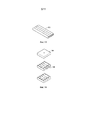
[00010] В некоторых вариантах реализации в пределах объема настоящего изобретения фильтр включает в себя плоскую пластину мембранного фильтра или половолоконную мембрану, которая расположена в ряд со стержнем между первой и второй частями стержня. Конусная головка стержня может представлять собой фитинг с охватывающим концом, который герметично соединяется с фитингом Люэра. При такой конфигурации раствор может поступать через впускное отверстие стержня и последовательно проходить через головку в первую часть по направлению к впускному отверстию фильтра. Затем раствор фильтруется через мембрану фильтра, выходит через выпускное отверстие фильтра и попадает во вторую часть стержня. Трубка обеспечивает жидкостное соединение отфильтрованного раствора из второй части и отверстия камеры. Вторая часть стержня, определенная как область стержня между выпускным отверстием фильтра и впускным отверстием трубки, может быть обозначена как участок отрезания и герметизации. Стержень обеспечивает изолированное жидкостное соединение между впускным отверстием и камерой таким образом, что после фильтрации раствора через мембрану отфильтрованный раствор попадает прямо в постерилизованную среду камеры. [00010] In some embodiments within the scope of the present invention, the filter includes a flat membrane filter plate or hollow fiber membrane that is aligned with the rod between the first and second rod portions. The tapered stem head can be a female end fitting that seals with a Luer fitting. With this configuration, the solution can enter through the inlet of the rod and pass sequentially through the head into the first portion towards the inlet of the filter. The solution is then filtered through the filter membrane, exits through the filter outlet and into the second part of the rod. The tube provides a fluid connection of the filtered solution from the second part and the chamber opening. The second rod portion, defined as the area of the rod between the filter outlet and the tube inlet, may be referred to as the cutting and sealing portion. The rod provides an isolated fluid connection between the inlet and the chamber so that after filtration of the solution through the membrane, the filtered solution enters directly into the sterilized environment of the chamber.
[00011] В других вариантах реализации в пределах объема настоящего изобретения стержень, который может быть конусообразным или цилиндрическим, не обеспечивает отдельные соединительные порта для фильтра на впускном отверстии и выпускном отверстии. Вместо этого фильтр включает в себя половолоконную мембрану фильтра, которая соответствует форме стержня. В некоторых вариантах реализации в пределах объема настоящего изобретения набор избыточных фильтров, расположенных последовательно в стержне, может использоваться вместе с мешком с продуктом. В некоторых вариантах реализации в пределах объема настоящего изобретения одна или более закольцованных половолоконных мембран фильтров могут быть закреплены внутри корпуса фильтра для обеспечения более быстрой фильтрации. В других вариантах реализации в пределах объема настоящего изобретения множество половолоконных мембран фильтров могут быть расположены бок-о-бок или по кругу для образования связанной конфигурации, делающей возможной более быструю фильтрацию. [00011] In other embodiments within the scope of the present invention, the rod, which may be tapered or cylindrical, does not provide separate filter connection ports at the inlet and outlet. Instead, the filter includes a hollow fiber filter membrane that conforms to the shape of the rod. In some embodiments, within the scope of the present invention, a set of redundant filters in series in a rod may be used in conjunction with a product bag. In some embodiments within the scope of the present invention, one or more looped hollow fiber filter membranes may be secured within the filter housing to provide faster filtration. In other embodiments within the scope of the present invention, a plurality of hollow fiber filter membranes may be disposed side-by-side or in a circle to form a coherent configuration allowing for faster filtration.
[00012] В некоторых вариантах реализации в пределах объема данного изобретения мешки для продукта можно сконфигурировать таким образом, чтобы можно было использовать один единственный фильтр для обработки раствора из нескольких мешков с продуктом. Например, несколько камер для продукта могут располагаться, образовывая конфигурацию наподобие пояса, и подсоединяться к одному единственному фильтру, при этом отфильтрованный раствор заполняет камеры последовательно. В качестве альтернативного варианта, несколько камер могут быть подсоединены при помощи системы плотно закрывающихся трубок к одному фильтру. [00012] In some embodiments within the scope of the present invention, product bags may be configured to use a single filter to process a solution from multiple product bags. For example, multiple product chambers can be positioned in a belt-like configuration and connected to a single filter, with the filtered solution filling the chambers in series. Alternatively, multiple chambers can be connected with a tight-fitting tubing system to one filter.
[00013] Каждый фильтр является фильтром стерилизационного класса и содержит подходящий материал стерилизационного класса, имеющий множество пор; фильтр имеет номинальный размер пор в диапазоне от приблизительно 0,1 микрона до приблизительно 0,5 микрона, например, от приблизительно 0,2 до приблизительно 0,4 микрона. В некоторых вариантах каждая пора имеет диаметр, который меньше или равен приблизительно 0,2 микрона. В некоторых вариантах каждая пора имеет диаметр, который меньше или равен приблизительно 0,22 микрона. В некоторых вариантах фильтр имеет номинальный размер пор в диапазоне от приблизительно 0,1 микрона до приблизительно 0,2 микрона. В некоторых вариантах фильтр имеет номинальный размер пор в диапазоне от приблизительно 0,1 микрона до приблизительно 0,22 микрона. При характеристике пористости мембран фильтров «номинальный размер пор» обычно означает диаметр наименьшей частицы, которая не может пройти сквозь мембрану. Для определения номинального размера пор обычно используется порометрия. Большинство производителей мембранных фильтров характеризуют свои фильтры по первой точке разгазирования (FBP) согласно определению в стандарте Американского общества по испытанию материалов ASTM F-316-03 (2011) «Стандартные способы тестирования на характеристики размера пор мембранных фильтров по точке разгазирования и с помощью испытания на средний поток через пору». Номинальный размер поры рассчитывается на основании FBP с использованием формулы Юнга-Лапласа P= 4*γ*cos θ*/D, где D - это диаметр поры, P - это измеренное давление, γ - это поверхностное натяжение смачивающей жидкости, а θ - это угол контакта смачивающей жидкости с образцом. В одном испытании подходящая скорость потока для измерения FBP могла бы быть примерно 30 мл/мин. [00013] Each filter is a sterilization grade filter and contains a suitable sterilization grade material having multiple pores; the filter has a nominal pore size in the range of about 0.1 micron to about 0.5 micron, such as about 0.2 to about 0.4 micron. In some embodiments, each pore has a diameter less than or equal to about 0.2 microns. In some embodiments, each pore has a diameter less than or equal to about 0.22 microns. In some embodiments, the filter has a nominal pore size ranging from about 0.1 micron to about 0.2 micron. In some embodiments, the filter has a nominal pore size ranging from about 0.1 micron to about 0.22 micron. When characterizing the porosity of filter membranes, “nominal pore size” generally refers to the diameter of the smallest particle that cannot pass through the membrane. Porosimetry is commonly used to determine the nominal pore size. Most membrane filter manufacturers characterize their filters on the first bubble point (FBP) as defined in the American Society for Testing Materials ASTM F-316-03 (2011) Standard Test Methods for Pore Size Characteristics of Membrane Filters by Point of Gas and by Testing for average flow through the pore ". The nominal pore size is calculated from the FBP using the Young-Laplace formula P = 4 * γ * cos θ * / D, where D is the pore diameter, P is the measured pressure, γ is the surface tension of the wetting liquid, and θ is the angle of contact of the wetting liquid with the sample. In one test, a suitable flow rate for measuring FBP would be about 30 ml / min.
[00014] Фильтр такой конструкции эффективно стерилизует и снижает уровень содержания твердых частиц в растворе по мере того, как раствор проходит сквозь фильтр и в камеру. Наполнение мешка для продукта может выполняться при температуре свыше 60°С для составов, которые являются совместимыми, таким образом, чтобы остаточные риски прохождение микробиальных загрязнений живыми организмами сквозь фильтр еще больше снижались посредством пастеризации или аналогичной термообработки в дополнение к фильтрации. В качестве альтернативы горячее наполнение может быть заменено процессом стерилизации непосредственно перед наполнением, таким как УФ-стерилизация, тепловая стерилизация, стерилизация электронным излучением и т.п. [00014] A filter of this design effectively sterilizes and reduces the level of solids in the solution as the solution passes through the filter and into the chamber. Filling of the product bag can be carried out at temperatures above 60 ° C for formulations that are compatible, so that the residual risks of microbial contamination from living organisms passing through the filter are further reduced by pasteurization or similar heat treatment in addition to filtration. Alternatively, hot filling can be replaced by a sterilization process just prior to filling such as UV sterilization, heat sterilization, electron beam sterilization, and the like.
[00015] В некоторых вариантах реализации конфигурации фильтра, раскрытые в настоящем документе, могут быть подсоединены к контейнерной системе для проведения постоянного амбулаторного перитонеального диализа (ПАПД) с двумя мешками. Контейнерная система ПАПД с двумя мешками позволяет вводить важные для перитонеального диализа растворы пациентам с терминальной стадией почечной недостаточности в местах, где в противном случае лечение таких пациентов могло не быть возможным. Контейнерная система с двумя мешками включает в себя мешок для раствора и дренажный мешок. На мешке для раствора может быть предусмотрено инъекционное поле для медикаментозных добавок. Система трубок идет от мешка для раствора и дренажного мешка к коннектору пациента. Коннектор пациента сопрягается с системой переливания катетера для перитонеального диализа (ПД) пациента во время использования. Коннектор пациента может иметь тройник, к которому подсоединяются трубки. Трубки, идущие от мешка для раствора до коннектора пациента, могут иметь хрупкий участок прямо перед коннектором пациента. Коннектор пациента может иметь защитный колпачок для обеспечения стерильности, который можно удалить непосредственно перед использованием. В некоторых вариантах реализации конфигурация фильтра может предусматривать подсоединение на тройнике фильтра к трубкам, идущим от мешка для раствора к коннектору пациента. В других вариантах реализации конфигурация фильтра может предусматривать подсоединение к мешку для раствора посредством трубок, совершенно отдельных от трубок, идущих от мешка для раствора к коннектору пациента. [00015] In some embodiments, the filter configurations disclosed herein may be connected to a dual-bag continuous ambulatory peritoneal dialysis (CAPD) container system. The CAPD container system with two bags allows the administration of solutions important for peritoneal dialysis to patients with end-stage renal disease in places where treatment of such patients might not otherwise be possible. The two-bag container system includes a solution bag and a drainage bag. The solution bag may have an injection field for medicinal additives. The tubing runs from the solution bag and drainage bag to the patient connector. The patient connector mates with the patient's peritoneal dialysis (PD) catheter transfusion system during use. The patient connector may have a tee to which the tubing is connected. The tubing from the solution bag to the patient connector may have a fragile portion just in front of the patient connector. The patient connector may have a protective cap to ensure sterility, which can be removed immediately prior to use. In some embodiments, the filter may be configured to connect at the filter tee to tubing from the solution bag to the patient connector. In other embodiments, the filter may be configured to be connected to the solution bag by means of tubes that are completely separate from the tubing from the solution bag to the patient connector.
[00016] В соответствии с первым независимым аспектом предоставляется мешок для стерильного раствора продукта, включая камеру, стержень и фильтр. Стержень имеет конец с впускным отверстием и конец с выпускным отверстием, конец с выпускным отверстием стержня находится в жидкостном соединении с камерой. Фильтр располагается соосно стержню, фильтр имеет мембрану фильтра с номинальным размером пор в диапазоне от приблизительно 0,1 мкм до приблизительно 0,5 мкм, при этом мембрана фильтра имеет форму половолокна с порами, расположенными в стенке волокна. [00016] According to a first independent aspect, a bag for a sterile product solution is provided, including a chamber, rod, and filter. The rod has an inlet end and an outlet end, the outlet end of the rod is in fluid communication with the chamber. The filter is coaxial to the rod, the filter has a filter membrane with a nominal pore size in the range of about 0.1 μm to about 0.5 μm, the filter membrane is in the form of a hollow fiber with pores located in the fiber wall.
[00017] Во втором аспекте согласно предыдущему аспекту мембрана фильтра расположена внутри стержня между краями с впускным отверстием и выпускным отверстием. [00017] In a second aspect according to the previous aspect, a filter membrane is disposed within the rod between the inlet and outlet edges.
[00018] В третьем аспекте согласно предыдущим аспектам фильтр содержит множество мембран фильтра. [00018] In a third aspect, according to the previous aspects, the filter comprises a plurality of filter membranes.
[00019] В четвертом аспекте согласно предыдущим аспектам конец с выпускным отверстием половолокна мембраны фильтра запечатан, а конец с впускным отверстием представляет собой открытое впускное отверстие. [00019] In a fourth aspect according to the previous aspects, the outlet end of the hollow fiber of the filter membrane is sealed, and the inlet end is an open inlet.
[00020] В пятом аспекте согласно предыдущим аспектам мембрана фильтра имеет толщину стенок в диапазоне от приблизительно 150 мкм до приблизительно 500 мкм. [00020] In a fifth aspect, according to the previous aspects, the filter membrane has a wall thickness in the range of about 150 microns to about 500 microns.
[00021] В шестом аспекте согласно предыдущим аспектам мембрана фильтра имеет продольный размер в диапазоне от приблизительно 3 см до приблизительно 20 см, внутренний диаметр в диапазоне от приблизительно 2 мм до приблизительно 4 мм и внешний диаметр в диапазоне от приблизительно 2,3 мм до приблизительно 5 мм. [00021] In a sixth aspect, according to previous aspects, the filter membrane has a longitudinal dimension in the range of about 3 cm to about 20 cm, an inner diameter in the range of about 2 mm to about 4 mm, and an outer diameter in the range of about 2.3 mm to about 5 mm.
[00022] В седьмом аспекте согласно предыдущим аспектам мембрана фильтра изготовлена из по меньшей мере одного из следующих материалов: полиолефина, поливинилиденфторида, полиметилметакрилата, полиакрилонитрила, полисульфона, полиэфирсульфона и полимера, содержащего заряды катиона. [00022] In a seventh aspect according to the previous aspects, the filter membrane is made from at least one of the following materials: polyolefin, polyvinylidene fluoride, polymethyl methacrylate, polyacrylonitrile, polysulfone, polyethersulfone, and a polymer containing cation charges.
[00023] В восьмом аспекте согласно предыдущим аспектам стержень является либо гибким, либо жестким. [00023] In an eighth aspect, according to the previous aspects, the rod is either flexible or rigid.
[00024] В девятом аспекте согласно предыдущим аспектам стержень изготовлен из по меньшей мере одного из следующих материалов: ПВХ, ПЭТ, поли(мет)акрилата, поликарбоната, полиолефина, сополимера циклоолефина, полистирола или силиконового полимера. [00024] In a ninth aspect, according to the previous aspects, the rod is made of at least one of the following materials: PVC, PET, poly (meth) acrylate, polycarbonate, polyolefin, cycloolefin copolymer, polystyrene, or silicone polymer.
[00025] В десятом аспекте согласно предыдущим аспектам фильтр включает в себя по меньшей мере одну U-образную половолоконную мембрану фильтра, закрепленную в U-образной конфигурации корпусом мембраны фильтра, находящимся внутри корпуса фильтра. [00025] In a tenth aspect according to previous aspects, the filter includes at least one U-shaped hollow fiber filter membrane secured in a U-shaped configuration by a filter membrane body disposed within the filter body.
[00026] В одиннадцатом аспекте согласно предыдущим аспектам фильтр содержит множество U-образных половолоконных мембран фильтра. [00026] In an eleventh aspect, according to the previous aspects, the filter comprises a plurality of U-shaped hollow fiber filter membranes.
[00027] В двенадцатом аспекте согласно предыдущим аспектам фильтр состоит из множества параллельных половолоконных мембранных фильтров, закрепленных в конфигурации «бок-о-бок». [00027] In a twelfth aspect, according to the previous aspects, the filter is composed of a plurality of parallel hollow fiber membrane filters fixed in a side-by-side configuration.
[00028] В тринадцатом аспекте согласно предыдущим аспектам фильтр состоит из множества параллельных половолоконных мембранных фильтров, расположенных по кругу. [00028] In a thirteenth aspect according to the previous aspects, the filter is composed of a plurality of parallel hollow fiber membrane filters arranged in a circle.
[00029] В четырнадцатом аспекте согласно предыдущим аспектам мембрана фильтра имеет номинальный размер пор в диапазоне от приблизительно 0,1 мкм до приблизительно 0,22 мкм. [00029] In a fourteenth aspect, according to the previous aspects, the filter membrane has a nominal pore size in the range of about 0.1 microns to about 0.22 microns.
[00030] В пятнадцатом аспекте согласно предшествующим аспектам мешок для стерильного раствора продукта состоит из множества камер, находящихся в прямом жидкостном соединении друг с другом, стержня и фильтра, соединенного с множеством камер для наполнения мешка с продуктом, при этом каждая камера соединена с по меньшей мере одной другой камерой по кромке между камерами, и каждая кромка имеет отверстие, через которое обеспечивается жидкостное соединение этих камер, причем единственный фильтр соединен с одной из камер посредством впускного отверстия. [00030] In a fifteenth aspect according to the foregoing aspects, the sterile product solution bag is composed of a plurality of chambers in direct fluid communication with each other, a rod and a filter connected to the plurality of chambers for filling the product bag, each chamber being connected to at least at least one other chamber along the edge between the chambers, and each edge has an opening through which a fluid connection of these chambers is provided, and a single filter is connected to one of the chambers through an inlet.
[00031] В шестнадцатом аспекте согласно предыдущим аспектам мешок для стерильного раствора продукта содержит множество камер, находящихся в жидкостном соединении друг с другом посредством системы плотно закрывающихся трубок, стержень и фильтр, соединенный с множеством камер для наполнения мешка с продуктом, при этом система плотно закрывающихся трубок состоит из первой части, которая идет до соединения, и множества вторых частей, которые идут от соединения к множеству камер, каждая вторая часть идет к одной камере. [00031] In a sixteenth aspect according to the previous aspects, the bag for the sterile product solution comprises a plurality of chambers in fluid communication with each other through a tight-fitting tubing system, a rod and a filter connected to the plurality of chambers for filling the product bag, the tight-fitting system of tubes consists of a first part that goes up to the connection and a plurality of second parts that go from the connection to a plurality of chambers, every second part going to one chamber.
[00032] В соответствии с семнадцатым независимым аспектом предоставляется мешок для стерильного раствора продукта, содержащий камеру, стержень и фильтр. Стержень имеет конец с впускным отверстием и конец с выпускным отверстием, конец с выпускным отверстием стержня находится в жидкостном соединении с камерой. Фильтр включает в себя пористую мембрану фильтра, расположенную внутри стержня, при этом мембрана фильтра представляет собой полый цилиндр с закрытым концом, расположенным между концами стержня с впускным отверстием и выпускным отверстием, и открытым концом, расположенным в непосредственной близости от конца стержня с впускным отверстием. Коннектор соединен с концом стержня с впускным отверстием и с открытым концом фильтра; коннектор имеет впускное отверстие для раствора, выпускное отверстие для раствора и уплотняющую поверхность, расположенную между впускным отверстием для раствора и выпускным отверстием для раствора; выпускное отверстие для раствора соединено с открытым концом фильтра, а уплотняющая поверхность соединена с концом стержня с впускным отверстием; впускное отверстие для раствора адаптировано для принятия раствора с целью фильтрации через стержень и в камеру. [00032] In accordance with a seventeenth independent aspect, a sterile product solution bag is provided comprising a chamber, a rod, and a filter. The rod has an inlet end and an outlet end, the outlet end of the rod is in fluid communication with the chamber. The filter includes a porous filter membrane located within the rod, the filter membrane being a hollow cylinder with a closed end located between the inlet and outlet rod ends and an open end located in close proximity to the inlet rod end. The connector is connected to the inlet end of the rod and to the open end of the filter; the connector has a solution inlet, a solution outlet, and a sealing surface disposed between the solution inlet and the solution outlet; the solution outlet is connected to the open end of the filter, and the sealing surface is connected to the inlet end of the rod; the solution inlet is adapted to receive the solution for filtration through the rod and into the chamber.
[00033] В восемнадцатом аспекте согласно предыдущим аспектам пористая мембрана фильтра имеет номинальный размер пор в диапазоне от приблизительно 0,1 мкм до приблизительно 0,5 мкм. [00033] In an eighteenth aspect according to the previous aspects, the porous filter membrane has a nominal pore size in the range of about 0.1 microns to about 0.5 microns.
[00034] В девятнадцатом аспекте согласно предыдущим аспектам мембрана фильтра имеет номинальный размер пор в диапазоне от приблизительно 0,1 мкм до приблизительно 0,22 мкм. [00034] In a nineteenth aspect, according to the previous aspects, the filter membrane has a nominal pore size in the range of about 0.1 microns to about 0.22 microns.
[00035] В двадцатом аспекте согласно предыдущим аспектам конец стержня с впускным отверстием прикреплен к уплотняющей поверхности коннектора, а открытый конец фильтра прикреплен к выпускному отверстию для раствора коннектора. [00035] In a twentieth aspect according to the previous aspects, the inlet rod end is attached to the sealing surface of the connector, and the open end of the filter is attached to the solution outlet of the connector.
[00036] В двадцать первом аспекте согласно предыдущим аспектам выпускное отверстие коннектора состоит из цилиндрического элемента, расположенного внутри открытого конца фильтра. [00036] In a twenty-first aspect according to the previous aspects, the connector outlet is comprised of a cylindrical member disposed within an open end of the filter.
[00037] В двадцать втором аспекте согласно предыдущим аспектам фильтр содержит множество мембран фильтра. [00037] In a twenty-second aspect according to previous aspects, the filter comprises a plurality of filter membranes.
[00038] В двадцать третьем аспекте согласно предыдущим аспектам мембрана фильтра имеет толщину стенок в диапазоне от приблизительно 150 мкм до приблизительно 500 мкм. [00038] In a twenty-third aspect according to previous aspects, the filter membrane has a wall thickness in the range of about 150 microns to about 500 microns.
[00039] В двадцать четвертом аспекте согласно предыдущим аспектам мембрана фильтра имеет продольный размер в диапазоне от приблизительно 3 см до приблизительно 20 см, внутренний диаметр в диапазоне от приблизительно 2 мм до приблизительно 4 мм и внешний диаметр в диапазоне от приблизительно 2,3 мм до приблизительно 5 мм. [00039] In a twenty-fourth aspect according to the previous aspects, the filter membrane has a longitudinal dimension in the range of about 3 cm to about 20 cm, an inner diameter in the range of about 2 mm to about 4 mm, and an outer diameter in the range of about 2.3 mm to approx. 5 mm.
[00040] В двадцать пятом аспекте согласно предыдущим аспектам мембрана фильтра изготовлена из по меньшей мере одного из следующих материалов: полиолефина, поливинилиденфторида, полиметилметакрилата, полиакрилонитрила, полисульфона, полиэфирсульфона и полимера, содержащего заряды катиона. [00040] In a twenty-fifth aspect according to the previous aspects, the filter membrane is made of at least one of the following materials: polyolefin, polyvinylidene fluoride, polymethyl methacrylate, polyacrylonitrile, polysulfone, polyethersulfone, and a polymer containing cation charges.
[00041] В двадцать шестом аспекте согласно предыдущим аспектам стержень является либо гибким, либо жестким. [00041] In a twenty-sixth aspect, according to the previous aspects, the rod is either flexible or rigid.
[00042] В двадцать седьмом аспекте согласно предыдущим аспектам стержень изготовлен из по меньшей мере одного из следующих материалов: ПВХ, ПЭТ, поли(мет)акрилата, поликарбоната, полиолефина, сополимера циклоолефина, полистирола или силиконового полимера. [00042] In a twenty-seventh aspect according to the previous aspects, the rod is made of at least one of the following materials: PVC, PET, poly (meth) acrylate, polycarbonate, polyolefin, cycloolefin copolymer, polystyrene, or silicone polymer.
[00043] В двадцать восьмом аспекте согласно предыдущим аспектам мешок для стерильного раствора продукта является частью контейнерной системы для проведения постоянного амбулаторного перитонеального диализа (ПАПД) с двумя мешками, которая, в свою очередь, состоит из дренажного мешка и коннектора пациента с тройником, соединенным с первой системой трубок, присоединенной к мешку с продуктом, и со второй системой трубок, присоединенной к дренажному мешку. [00043] In a twenty-eighth aspect according to the previous aspects, the bag for sterile product solution is part of a container system for performing continuous ambulatory peritoneal dialysis (CAPD) with two bags, which, in turn, consists of a drainage bag and a patient connector with a tee connected to a first tubing connected to the product bag; and a second tubing connected to a drainage bag.
[00044] В двадцать девятом аспекте согласно предыдущим аспектам на мешке для продукта предусмотрено инъекционное поле. [00044] In a twenty-ninth aspect, according to the previous aspects, an injection field is provided on the product bag.
[00045] В тридцатом аспекте согласно предыдущим аспектам первая система трубок, присоединенная к мешку с продуктом, имеет хрупкий участок. [00045] In a thirtieth aspect according to the previous aspects, the first tubing connected to the product bag has a fragile portion.
[00046] В тридцать первом аспекте согласно предыдущим аспектам коннектор пациента имеет защитный колпачок для обеспечения стерильности. [00046] In a thirty-first aspect according to the previous aspects, the patient connector has a protective cap to ensure sterility.
[00047] В тридцать втором аспекте согласно предыдущим аспектам выпускное отверстие стержня соединено с тройником, расположенным вдоль первой системы трубок, присоединенной к мешку с продуктом. [00047] In a thirty-second aspect according to the previous aspects, the stem outlet is connected to a tee located along the first tubing connected to the product bag.
КРАТКОЕ ОПИСАНИЕ ГРАФИЧЕСКИХ МАТЕРИАЛОВBRIEF DESCRIPTION OF THE GRAPHIC MATERIALS
[00048] Хотя спецификация завершается формулой изобретения, в частности, указывающей и четко заявляющей об объекте изобретения, который считается раскрытым в данном документе, считается, что раскрытую таким образом информацию можно лучше понять на основании следующего описания в сочетании с сопроводительными графическими материалами. Некоторые из фигур, возможно, были упрощены посредством опущения избранных элементов в целях более четкого отображения других элементов. Такие опущения элементов на некоторых фигурах не обязательно указывают на наличие или отсутствие конкретных элементов в любом из вариантов реализации, приводимом в качестве примера, кроме случаев, когда в соответствующем письменном описании четко указано иное. Ни один из чертежей не является выполненным в масштабе в обязательном порядке. [00048] While the specification concludes with claims particularly indicating and clearly stating the subject matter deemed disclosed herein, it is believed that the information thus disclosed may be better understood based on the following description in conjunction with the accompanying drawings. Some of the figures may have been simplified by omitting selected items to display other items more clearly. Such omissions of elements in some figures do not necessarily indicate the presence or absence of specific elements in any of the exemplary embodiments, unless otherwise clearly indicated in the associated written description. None of the drawings are necessarily drawn to scale.
[00049] На ФИГ. 1 проиллюстрирован вид спереди мешка для продукта с плоской пластиной мембранного фильтра, расположенной соосно стержню мешка для продукта в соответствии с идеями настоящего изобретения. [00049] FIG. 1 illustrates a front view of a product bag with a flat membrane filter plate coaxial to the core of the product bag in accordance with the teachings of the present invention.
[00050] На ФИГ. 2 проиллюстрирован вид сбоку мешка для продукта по ФИГ. 1. [00050] FIG. 2 illustrates a side view of the product bag of FIG. 1.
[00051] На ФИГ. 3 проиллюстрирован вид спереди мешка с продуктом, имеющего половолоконную мембрану фильтра, расположенную соосно стержню мешка для продукта в соответствии с идеями настоящего изобретения. [00051] FIG. 3 illustrates a front view of a product bag having a hollow fiber filter membrane coaxial to the core of the product bag in accordance with the teachings of the present invention.
[00052] На ФИГ. 4 проиллюстрирован вид сбоку мешка для продукта по ФИГ. 3. [00052] FIG. 4 illustrates a side view of the product bag of FIG. 3.
[00053] На ФИГ. 5 проиллюстрировано развернутое изометрическое изображение фильтра и стержня, проиллюстрированных на ФИГ. 3 и 4. [00053] FIG. 5 is an exploded isometric view of the filter and rod illustrated in FIG. 3 and 4.
[00054] На ФИГ. 6 проиллюстрирован вид в перспективе альтернативного коннектора для использования с фильтром и стержнем, как тот, что проиллюстрирован на ФИГ. 3-5. [00054] FIG. 6 illustrates a perspective view of an alternative connector for use with a filter and rod such as the one illustrated in FIG. 3-5.
[00055] На ФИГ. 7 проиллюстрировано поперечное сечение коннектора по ФИГ. 6. [00055] FIG. 7 illustrates a cross-section of the connector of FIG. 6.
[00056] На ФИГ. 8 проиллюстрирован вид сбоку коннектора по ФИГ. 6. [00056] FIG. 8 illustrates a side view of the connector of FIG. 6.
[00057] На ФИГ. 9 проиллюстрирован вид снизу коннектора по ФИГ. 8. [00057] FIG. 9 illustrates a bottom view of the connector of FIG. 8.
[00058] На ФИГ. 10 проиллюстрирован вид сверху коннектора по ФИГ. 8. [00058] FIG. 10 illustrates a top view of the connector of FIG. 8.
[00059] На ФИГ. 11 проиллюстрирован вид спереди фильтра для мешка с продуктом, имеющего одну закольцованную половолоконную мембрану, содержащуюся внутри корпуса фильтра. [00059] FIG. 11 is a front view of a product bag filter having a single looped hollow fiber membrane contained within a filter housing.
[00060] На ФИГ. 12 проиллюстрирован вид спереди фильтра для мешка с продуктом, имеющего множество закольцованных половолоконных мембран, содержащихся внутри корпуса фильтра. [00060] FIG. 12 is a front view of a product bag filter having a plurality of looped hollow fiber membranes contained within a filter housing.
[00061] На ФИГ. 13 проиллюстрирован вид спереди множества половолоконных мембран, закрепленных «бок-о-бок». [00061] FIG. 13 illustrates a front view of a plurality of hollow fiber membranes secured side-by-side.
[00062] На ФИГ. 14 проиллюстрировано изометрическое изображение устройства крепления, используемого для множества половолоконных мембран, проиллюстрированных на ФИГ. 13. [00062] FIG. 14 is an isometric view of an attachment device used for the plurality of hollow fiber membranes illustrated in FIG. 13.
[00063] На ФИГ. 15 проиллюстрировано изометрическое изображение волоконного жгута для мешка с продуктом, имеющего множество половолоконных мембран, закрепленных в кольцевом держателе. [00063] FIG. 15 is an isometric view of a fiber bundle for a product bag having a plurality of hollow fiber membranes secured in an annular holder.
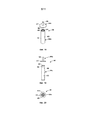
[00064] На ФИГ. 16 проиллюстрирован развернутый вид в перспективе альтернативного коннектора для использования со жгутом фильтров из трех фильтров. [00064] FIG. 16 is an exploded perspective view of an alternate connector for use with a three filter harness.
[00065] На ФИГ. 17 проиллюстрирован развернутый вид сбоку коннектора по ФИГ. 16. [00065] FIG. 17 is an exploded side view of the connector of FIG. sixteen.
[00066] На ФИГ. 18 проиллюстрирован развернутый вид в перспективе еще одного альтернативного коннектора для использования со жгутом фильтров из семи фильтров. [00066] FIG. 18 is an exploded perspective view of yet another alternative connector for use with a seven filter harness.
[00067] На ФИГ. 19 проиллюстрирован развернутый вид сбоку коннектора по ФИГ. 18. [00067] FIG. 19 is an exploded side view of the connector of FIG. 18.
[00068] На ФИГ. 20 проиллюстрирован вид снизу коннектора по ФИГ. 19. [00068] FIG. 20 illustrates a bottom view of the connector of FIG. nineteen.
[00069] На ФИГ. 21 проиллюстрирован вид спереди многочисленных мешков для продукта с плотно закрывающимися соединениями в ленточной конфигурации, соединенными с одним фильтром. [00069] FIG. 21 illustrates a front view of multiple product bags with tight-fit connections in a belt configuration coupled to a single filter.
[00070] На ФИГ. 22 проиллюстрирован вид спереди многочисленных мешков с продуктом, присоединенных при помощи системы плотно закрывающихся трубок к одному фильтру. [00070] FIG. 22 illustrates a front view of multiple bags of product connected by a tight-fitting tubing system to a single filter.
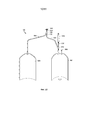
[00071] На ФИГ. 23 проиллюстрирован вид спереди контейнерной системы для проведения постоянного амбулаторного перитонеального диализа (ПАПД) с двумя мешками, присоединенной к одной из конфигураций фильтров, раскрытой в настоящем документе, посредством асимметричного тройника в системе трубок, идущих от мешка для раствора системы к коннектору пациента системы; и [00071] FIG. 23 illustrates a front view of a continuous ambulatory peritoneal dialysis (CAPD) container system with two bags attached to one of the filter configurations disclosed herein by means of an asymmetric tee in a tubing system extending from the solution bag of the system to the patient connector of the system; and
[00072] На ФИГ. 24 проиллюстрирован вид спереди контейнерной системы для проведения постоянного амбулаторного перитонеального диализа (ПАПД) с двумя мешками, присоединенной к одной из конфигураций фильтров, раскрытой в настоящем документе, посредством прямых трубок, идущих от мешка для раствора системы к конфигурации фильтров. [00072] FIG. 24 illustrates a front view of a continuous ambulatory peritoneal dialysis (CAPD) container system with two bags attached to one of the filter configurations disclosed herein via straight tubing extending from the system solution bag to the filter configuration.
ПОДРОБНОЕ ОПИСАНИЕ СУЩНОСТИ ИЗОБРЕТЕНИЯDETAILED DESCRIPTION OF THE INVENTION
[00073] Если подробно говорить о фигурах, на ФИГ. 1 и 2 проиллюстрирован мешок для продукта 100, имеющий предварительно постерилизованное внутреннее пространство и включающий в себя камеру 102, стержень 104, фильтр 106, расположенный соосно стержню 104, и стерильный запорный колпачок 108. Камера 102 представляет собой заполняемый пакет стандартной емкости с предварительно постерилизированной внутренней средой. По меньшей мере частично окружает периметр заполняемого пакета запечатанный край 110, имеющий множество отверстий 112, конфигурация которых обеспечивает принятие крепежных штырьков для подвешивания во время наполнения, введения и/или хранения. Камера 102 находится в жидкостном соединении со стержнем 104 через отверстие 114 на первом конце 116 камеры 102. Порты для введения и для лекарств 118, 120 расположены на втором конце 122 камеры 102. [00073] Referring to the figures in detail, FIG. 1 and 2 illustrate a
[00074] Стержень 104 представляет собой полую узкую трубку с впускным отверстием 124, находящимся в жидкостном соединении с отверстием 114 камеры 102. Стержень 104 включает в себя конусную головку 126, ограничивающую впускное отверстие 124, муфту 128, соединяющую первую часть стержня 130 с конусной головкой 126, вторую часть 132 и трубку 134, ограничивающую выпускное отверстие 136 стержня. Стерильный запорный колпачок 108 имеет выступ полусферической формы 138, присоединенный к шейке 140, которая герметично закрывает впускное отверстие 124 стержня 104. Конусная головка 126 может представлять собой фитинг с охватывающим концом, адаптированный для герметичного соединения с фитингом Люэра линии подачи жидкости во время наполнения, например. Фильтр 106, имеющий плоскую пластину мембраны 142, расположен соосно стержню 104 между первой и второй частями 130, 132 стержня 104. Примеры приемлемых мембран фильтра для мембраны фильтра 142, имеющие неограничивающий характер, раскрыты в публикации патента США № 2012/0074064 A1 и публикации PCT № PCT/EP2015/068004, полное содержание которых включено в данный документ посредством ссылки. [00074] The
[00075] При такой конфигурации раствор может проходить через впускное отверстие 124 стержня 104 и проходить сквозь головку 126 и в первую часть 130 в направлении впускного отверстия 144 фильтра 106. Затем раствор фильтруется через мембрану фильтра 142, выходит из выпускного отверстия фильтра 146 и во вторую часть 132 стержня 104. По трубке 134 отфильтрованный раствор попадает из второй части 132 в отверстие 114 камеры 102. Вторая часть 132 стержня 104, определенная как область стержня между выпускным отверстием фильтра 146 и впускным отверстием 148 трубки 134, может быть обозначена как «участок герметизации и отрезания». Фраза «участок герметизации и отрезания» касается способа, при помощи которого мешки для продукта герметизируются и отрезаются после наполнения. То есть, раскрываемая конфигурация имеет конструкцию, при которой после наполнения камеры 102 может быть задействован механизм герметизации для запечатывания стержня 104, закрытого на «участке герметизации и отрезания», находящемся под мембраной фильтра 142, но над камерой 102. Таким образом, «участок герметизации и отрезания» 132 в данной версии является участком стержня 104 над камерой 102, где фильтр 106 отсутствует. Запечатывание «участка герметизации и отрезания» 132 может осуществляться при помощи устройства для термогерметизации или любого другого устройства, включая, к примеру, наложения зажима на «участок герметизации и отрезания» 132. Как только стержень 104 запечатан, стержень 104 отрезается над местом герметизации, но под мембраной фильтра 142, при помощи ножа или любого другого устройства. Стержень 104 обеспечивает изолированное жидкостное соединение между впускным отверстием 124 и камерой 102 таким образом, что после фильтрации раствора сквозь мембрану фильтра 142 отфильтрованный раствор попадает прямо в стерилизованную среду камеры 102. Таким образом, после того, как камера 102 наполнена, а стержень 104 герметизирован и отрезан, раствор в камере 102 остается стерильным до тех пор, пока камера 102 не будет проколота, или пока ее целостность не будет нарушена иным образом. Это, конечно же, предполагает, что характеристики фильтра 106 не ухудшились до наполнения, и фильтр работает как положено. [00075] With this configuration, the solution can pass through the
[00076] Чтобы убедиться, что фильтр 106 работал должным образом, можно провести испытание фильтра 106 на целостность. Испытание фильтра на целостность упрощается образованием «участка герметизации и отрезания» (вторая часть 132) стержня 104, что позволяет отделить мембрану фильтра 142 от остальной части теперь уже запечатанного мешка для продукта 100, не повредив ее. Например, после отделения стержня 104 и фильтра 106 от мешка для продукта 100 устройство для испытания фильтра (не показано) можно запрограммировать заранее, или можно управлять им для проведения испытания фильтра 106 на целостность. Примеры испытаний фильтра на целостность могут включать в себя испытание на образование пузырей, проверку ухудшения характеристик под давлением, испытание на проникание воды, испытание проливом воды или любые подходящие испытания, известные специалистам в данной сфере. Проверка ухудшения характеристик под давлением является способом проверки качества фильтра до или после его использования. В предпочитаемом варианте реализации фильтр 106 испытывается после прохождения раствора сквозь мембрану фильтра 142 и в камеру 102 мешка для продукта 100. Для проведения испытания фильтра на целостность с использованием процедуры проверки ухудшения характеристик под давлением тестовая головка (не показана) охватывает стержень 104 и подает давление воздуха заранее установленной величины на впускное отверстие 124 и мембрану фильтра 142. В одном варианте реализации это заранее установленное значение является давлением, при котором газ не может проникнуть сквозь мембрану фильтра 142 приемлемого фильтра 106. Датчик давления или иное устройство для измерения целостности фильтра расположено внутри тестовой головки и измеряет падение давления или скорость диффузии сквозь мембрану фильтра 142. Результаты испытания на целостность оцениваются для определения качества фильтра 106 и, следовательно, качества раствора, который ранее проходил сквозь фильтр 106 и в мешок для продукта 100. Если датчик давления измеряет падение давления или неожиданную скорость падения, значит, фильтр 106 не прошел испытание, и можно определить, что раствор в мешке для продукта является неудовлетворительным. В качестве альтернативы, в ходе испытания на образование пузырей тестовая головка постепенно увеличивает давление, оказываемое на фильтр 106, и увеличение давления измеряется параллельно со скоростью диффузии газа сквозь мембрану фильтра 142. Любое непропорциональное увеличение скорости диффузии относительно оказываемого давления может указывать на наличие отверстия или иного структурного дефекта в мембране фильтра 142, и фильтр не пройдет испытание на целостность. [00076] To ensure that the
[00077] Таким образом, следует принять во внимание, что раскрываемая конфигурация «участка герметизации и отрезания» 132 мешка для продукта 100, раскрываемая в настоящем документе, обеспечивает преимущество и упрощает проведение испытания на целостность фильтра, а также позволяет с высокой степенью вероятности определить, является ли раствор в заполненном мешке для продукта стерильным, или же существует вероятность того, что его стерильность была нарушена. [00077] Thus, it should be appreciated that the disclosed "seal and cut"
[00078] Альтернативный мешок для продукта 150, проиллюстрированный на ФИГ. 3-5, включает в себя аналогичную камеру 152 и стерильный запорный колпачок 154, как и в первом мешке для продукта100. На ФИГ. 3-5 мешок для продукта 150 содержит фильтр 155, состоящий из мембраны фильтра 170, расположенной внутри (то есть, по меньшей мере, частично или полностью внутри) стержня 156. Стержень 156, который может быть конусным или цилиндрическим, не обеспечивает отдельные впускной и выпускной соединительные порты для фильтра 155, как проиллюстрировано в случае мешка для продукта 100 на ФИГ. 1 и 2. Вместо этого, как проиллюстрировано на ФИГ. 5, фильтр 155 представляет собой половолоконную мембрану с одним запечатанным концом 158 и одним открытым концом с впускным отверстием 160. Множество пор 162 на поверхности 164 фильтра 155 позволяют фармацевтическому раствору, который поступает на фильтр 155 через отрытый конец с впускным отверстием 160, покидать фильтр 155. В одном варианте стержень 156 окружает мембрану фильтра 170 в целом в рамках концентрической конфигурации таким образом, что отфильтрованный фармацевтический раствор, покидающий мембрану фильтра 170, удерживается внутри стержня 156 и в конечном итоге перемещается в камеру 152. Снова, как проиллюстрировано на ФИГ. 1 и 2, мешок для продукта на ФИГ. 3-55 включает в себя «участок герметизации и отрезания» 132 под фильтром 155 и над камерой 152, причем «участок герметизации и отрезания» 132 упрощает отделение той части стержня 156, содержащей мембрану фильтра 170. Благодаря существованию «участка герметизации и отрезания» 132 мембрана фильтра 170 может быть отделена без нарушения ее целостности. Как описано выше в отношении ФИГ. 1 и 2, этот «участок герметизации и отрезания» 132 может обеспечить преимущество посредством упрощения проведения испытания на целостность фильтра 155. [00078] An
[00079] Как проиллюстрировано на ФИГ. 5, полый коннектор 166 может использоваться для скрепления стержня 156 и фильтра 155 вместе. Открытый конец с впускным отверстием 160 фильтра 155 герметично соединен с открытым концом с выпускным отверстием 168 полого коннектора 166. Соединение может достигаться посредством приклеивания открытого конца с впускным отверстием 160 фильтра 155 к открытому концу с выпускным отверстием 168 коннектора 166 при помощи, например, эпоксидной смолы, полиуретановой смолы, циноакрилатной смолы, УФ-отверждаемого акрилового клея или растворителя для материала полого коннектора 166, такого как циклогексанон. В проиллюстрированном варианте открытый конец с выпускным отверстием 168 коннектора 166 содержит полый цилиндрический элемент, который помещается внутри и крепится к открытому концу с впускным отверстием 160 фильтра 155. Соответственно, внешний диаметр открытого конца с выпускным отверстием 168 коннектора 166 в существенной степени аналогичен или немного меньше, чем внутренний диаметр открытого конца с впускным отверстием 160 фильтра 155. В некоторых вариантах открытый конец с впускным отверстием 160 фильтра 155 может быть приварен к открытому концу с выпускным отверстием 168 коннектора 166 посредством, например, термической сварки (например, введения горячего конического металлического наконечника в открытый конец с впускным отверстием 150 фильтра 155, чтобы его частично расплавить), лазерной сварки, если полый коннектор 166 изготовлен из материала, который поглощает лазерное излучение, зеркальной сварки, ультразвуковой сварки и сварки трением. В качестве альтернативного варианта, фильтр 155 может вставляться в форму, и вокруг него может заливаться под давлением термопластичный полимер для формирования полого коннектора 166. Другие конструкции и конфигурации для присоединения фильтра 155 к коннектору 166 призваны находиться в пределах объема настоящего изобретения. [00079] As illustrated in FIG. 5, the
[00080] Полый коннектор 166 также включает в себя впускное отверстие для раствора 169. Фармацевтический раствор может подаваться через подсоединенную линию подачи жидкости, например, во впускное отверстие для раствора 169 полого коннектора 166. В некоторых вариантах впускное отверстие для раствора 169 может включать в себя фитинг Люэра или другой стандартный медицинский фитинг. Фармацевтический раствор затем может проходить через полый коннектор 166 и выходить в фильтр 155 через открытый конец с выпускным отверстием 168 полого коннектора 166. Полый коннектор 166 также имеет уплотняющую поверхность 172, к которой прикреплен стержень 156. Уплотняющая поверхность 172 в этом варианте является цилиндрической и имеет диаметр, который больше, чем диаметр открытого конца с выпускным отверстием 168, и расположена в целом концентрически относительно открытого конца с выпускным отверстием 168. На самом деле, в этом варианте внешний диаметр уплотняющей поверхности 172 в целом идентичен или немного меньше внутреннего диаметра стержня 156. При такой конфигурации стержень 156 принимает уплотняющую поверхность 172 и выходит из нее, охватывая и защищая фильтр 155, не контактируя с поверхностью 164 фильтра 155. Стержень 156 может быть прикреплен к уплотняющей поверхности 172 адгезивом (например, УФ-отверждаемым акриловым клеем), эпоксидной смолой, сваркой, склеиванием и т.п. Стержень 156 принимает фармацевтический раствор после того, как он проходит сквозь поры 162 в фильтре 155. Оттуда уже отфильтрованный раствор попадает в камеру 152. [00080] The
[00081] На ФИГ. 6-10 проиллюстрирован альтернативный полый коннектор 766, аналогичный коннектору 166, для скрепления стержня 156 и половолоконного фильтра 155 по ФИГ. 3-5 вместе. Коннектор 766 включает в себя открытый конец с выпускным отверстием 768, поддерживаемый конструкцией стержня, который выходит в первом направлении из опорной пластины 777 и приспосабливается для обеспечения герметичного соединения с открытым концом с впускным отверстием 160 фильтра 155. Это соединение может достигаться путем приклеивания открытого конца с впускным отверстием 160 фильтра 155 к открытому концу с выпускным отверстием 768 коннектора 766 с использованием, например, эпоксидной смолы, полиуретановой смолы, циноакрилатной смолы, УФ-отверждаемого акрилового клея или растворителя для материала полого коннектора 766, такого как циклогексанон. В проиллюстрированном варианте конструкция стержня на открытом конце с выпускным отверстием 768 коннектора 766 содержит полый цилиндрический элемент, который помещается внутри и крепится к открытому концу с впускным отверстием 160 фильтра 155. Соответственно, внешний диаметр открытого конца с выпускным отверстием 768 коннектора 766 в существенной степени аналогичен или немного меньше, чем внутренний диаметр открытого конца с впускным отверстием 160 фильтра 155. В некоторых вариантах открытый конец с впускным отверстием 160 фильтра 155 может быть приварен к открытому концу с выпускным отверстием 768 коннектора 766 посредством, например, термической сварки (например, введения горячего конического металлического наконечника в открытый конец с впускным отверстием 150 фильтра 155, чтобы частично его расплавить), лазерной сварки, если полый коннектор 766 изготовлен из материала, который поглощает лазерное излучение, зеркальной сварки, ультразвуковой сварки и сварки трением. В качестве альтернативного варианта, фильтр 155 может вставляться в форму, и вокруг него может заливаться под давлением термопластичный полимер для формирования полого коннектора 766. Другие конструкции и конфигурации для присоединения фильтра 155 к коннектору 766 призваны находиться в пределах объема настоящего изобретения. [00081] FIG. 6-10 illustrate an alternative
[00082] Полый коннектор 766 также включает в себя впускное отверстие для раствора 769, которое также является конструкцией стержня, выходящего во втором направлении (противоположном первому направлению) из опорной пластины 777. Фармацевтический раствор может подаваться через подсоединенную линию подачи жидкости, например, во впускное отверстие для раствора 769 полого коннектора 766. В некоторых вариантах впускное отверстие для раствора 769 может включать в себя фитинг Люэра или другой стандартный медицинский фитинг. Фармацевтический раствор может затем проходить через полый коннектор 766 и выходить в фильтр 155 через открытый конец с выпускным отверстием 768 полого коннектора 766. [00082] The
[00083] Полый коннектор 766 также имеет уплотняющую поверхность 772, к которой прикреплен стержень 156. Уплотняющая поверхность 772 в этом варианте представляет собой цилиндрический кожух, выходящий с опорной пластины 777 в первом направлении и имеющий диаметр, превышающий диаметр открытого конца с выпускным отверстием 768. Уплотняющая поверхность 772 расположена в целом концентрически относительно открытого конца с выпускным отверстием 768. Следовательно, в данном варианте реализации, кожух уплотняющей поверхности 772 окружает конструкцию стержня открытого конца с выпускным отверстием 768 таким образом, что между ними образуется кольцевой зазор 779. На самом деле, в данном варианте внешний диаметр уплотняющей поверхности 772 обычно идентичен или немного меньше внутреннего диаметра стержня 156. При такой конфигурации уплотняющая поверхность 772 коннектора 766 может сопрягаться со стержнем 156 таким образом, что стержень 156 выходит из нее и охватывает и защищает фильтр 155, не контактируя с поверхностью 164 фильтра 155. Стержень 156 может быть прикреплен к уплотняющей поверхности 772 при помощи адгезива (например, УФ-отверждаемого акрилового клея), эпоксидной смолы, сварки, склеивания и т.д. Стержень 156 принимает фармацевтический раствор после того, как он проходит через поры 162 в фильтре 155. Оттуда уже отфильтрованный раствор проходит в камеру 152 таким же образом, как описано выше в отношении ФИГ. 3-5. [00083] The
[00084] В то время как вышеуказанный вариант фильтра 155 был описан как включающий в себя одну мембрану фильтра 170, в других вариантах реализации в пределах объема настоящего изобретения фильтр 155 может включать в себя множественные мембраны фильтров 170. Несколько примеров множественных мембранных фильтров, не имеющих ограничительный характер, будут рассмотрены ниже. Наконец, как описано в отношении мешков для продукта 100, 150 по Фиг. 1-4, коннектор 166 на Фиг. 5 может включать в себя стерильный запорный колпачок 154, закрывающий впускное отверстие для раствора 168 для предотвращения попадания загрязняющих веществ в мешок для продукта до его наполнения. [00084] While the
[00085] В одном варианте следующего узла по Фиг. 5, и, как упоминалось, стержень 156 имеет внутренний диаметр, который больше, чем внешний диаметр мембраны фильтра 170, и стержень 156 имеет продольный размер, который больше, чем продольный размер мембраны фильтра 170. Следовательно, когда стержень 156 и мембрана фильтра 170 собираются на коннекторе 166, мембрана фильтра 170 располагается полностью внутри стержня 156, а между внутренней боковой стенкой стержня 156 и внешней боковой стенкой мембраны фильтра 170 существует зазор. Следовательно, раствор, проходящий сквозь мембрану фильтра 170, выходит из множества пор 162 и беспрепятственно течет сквозь этот зазор и по внутренней поверхности стержня 156 в камеру. В некоторых вариантах стержень 156 может представлять собой гибкую трубку, жесткую трубку или включать в себя трубку с гибкими участками и жесткими участками. В частности, в некоторых вариантах стержень 156 с по меньшей мере одним жестким участком, примыкающим к мембране фильтра 170, может служить для дополнительной защиты мембраны фильтра 170 и/или предотвращения прокола мембраны фильтра 170 или перекручивания на гибком участке трубки. В других вариантах такая защита может не потребоваться или не являться желательной. В одном варианте реализации стержень 156 имеет внутренний диаметр в диапазоне от приблизительно 2,5 мм до приблизительно 8 мм и продольный размер в диапазоне от приблизительно 5 см до приблизительно 30 см. В одном варианте реализации внутренний диаметр стержня 156 приблизительно на 0,2-3 мм больше, чем внешний диаметр мембраны фильтра 170. А мембрана фильтра 170 имеет внешний диаметр в диапазоне от приблизительно 2,3 мм до приблизительно 5 мм, продольный размер в диапазоне от приблизительно 3 см до приблизительно 20 см и толщину стенок в диапазоне от приблизительно 150 мкм до приблизительно 500 мкм. Более того, в одном варианте каждая из множества пор 162 в мембране фильтра 170 имеет диаметр меньше или равный приблизительно 0,2 микрона. В некоторых вариантах каждая пора имеет диаметр меньше или равный значению в диапазоне от приблизительно 0,1 микрона до приблизительно 0,5 микрона, например, от приблизительно 0,2 до приблизительно 0,4 микрона. В некоторых вариантах каждая пора имеет диаметр, который меньше или равен приблизительно 0,22 микрона. В некоторых вариантах каждая пора имеет диаметр, который меньше или равен значению в диапазоне от приблизительно 0,1 микрона до приблизительно 0,2 микрона. В некоторых вариантах каждая пора имеет диаметр, который меньше или равен значению в диапазоне от приблизительно 0,1 микрона до приблизительно 0,22 микрона. Такие размеры пор в сочетании с раскрытым геометрическим размером стержня 156 и мембраны фильтра 170 обеспечивают приемлемые скорости потока сквозь мембрану фильтра 170 для наполнения мешков для продукта инъекционными растворами для пациентов, такими как стерильная вода, стерильный физраствор и т.п. В других вариантах любой или все размеры могут отличаться в зависимости от конкретного применения. [00085] In one embodiment, the next node of FIG. 5, and, as mentioned, the
[00086] К подходящим материалам для мембраны фильтра 170 могут относиться полиолефины (например, ПЭ, ПП), поливинилиденфторид, полиметилметакрилат, полиакрилонитрил, полисульфон и полиэфирсульфон. В некоторых вариантах реализации в пределах объема настоящего изобретения фильтр 155 может быть изготовлен из смеси полисульфона или полиэфирсульфона и поливинилпирролидона. В других вариантах реализации в пределах объема настоящего изобретения мембрана фильтра 170 может включать в себя полимер, содержащий заряды катиона, например, полимеры, имеющие функциональные группы, такие как четвертичные аммониевые группы. Подходящим примером таких полимеров является полиэтиленимин. Мембрана фильтра 170 может быть изготовлена с использованием известных технологий, в том числе, например, экструзии, инверсии фаз, выдавливания, химического осаждения из паровой фазы, 3D-печати и т.д. Подходящие материалы для стержня 156 включают в себя ПВХ, полиэфиры, такие как ПЭТ, поли(мет)акрилаты, такие как ПММА, поликарбонаты (ПК), полиолефины, такие как ПЭ, ПП или сополимеры циклоолефина (СЦО), полистирол (ПС), кремнийорганические полимеры и т.п. [00086] Suitable materials for the
[00087] Дополнительная подробная информация о некоторых возможных вариантах фильтра и конкретной конструкции мембраны, например, приведена в заявке на европейский патент № EP 16152332.9 под названием «МЕМБРАНА ФИЛЬТРА И УСТРОЙСТВО», которая была подана 22 января 2016 г., а также в PCT/EP2017/051044 под названием «МЕМБРАНА ФИЛЬТРА И УСТРОЙСТВО», поданной 19 января 2017 г., все содержание каждой из которых явным образом включается в данный документ посредством ссылки. [00087] Further details of some possible filter options and a particular membrane design, for example, are found in European patent application No. EP 16152332.9 entitled "FILTER MEMBRANE AND DEVICE", which was filed January 22, 2016, as well as in PCT / EP2017 / 051044 entitled "FILTER MEMBRANE AND DEVICE" filed January 19, 2017, the entire content of each of which is expressly incorporated herein by reference.
[00088] До сих пор половолоконная мембрана 170 по ФИГ. 5, например, описывалась как расположенная внутри стержня 156. В других вариантах реализации фильтр 155 может иметь собственный корпус или иную опорную конструкцию, соединенную со стержнем 156 либо вместо коннектора 166 по ФИГ. 5 или коннектора 766 по ФИГ. 6-10, либо на участке между двумя частями стержня 156. [00088] So far, the
[00089] Например, на ФИГ. 11 проиллюстрирован вид спереди узла фильтра 400 для мешка для продукта (не показан), имеющего одну U-образную половолоконную мембрану фильтра 402, содержащуюся внутри корпуса фильтра 404. Мембрана фильтра 402 прикреплена к корпусу мембраны фильтра 406 в U-образной конфигурации при помощи адгезива (то есть, УФ-отверждаемого акрилового клея), эпоксидной смолы, сварки, склеивания или другими способами. Корпус мембраны фильтра 406 соединен с корпусом фильтра 404 на участке с выпускным отверстием 408 корпуса фильтра 404. Участок с впускным отверстием 410 герметично соединен с участком с выпускным отверстием 408 корпуса фильтра 404 в месте сочленения или ином месте соединения. Участок с впускным отверстием 410 корпуса фильтра 404 имеет впускное отверстие 412, через которое фармацевтический раствор может попасть в узел фильтра 400. Затем фармацевтический раствор поступает в мембрану фильтра 402 через множество пор 414, проходит сквозь мембрану фильтра 402, выходит из мембраны фильтра 402 через выпускные отверстия мембраны фильтра 416 и покидает корпус фильтра 404 через выпускное отверстие фильтра 418. Выпускное отверстие фильтра 418 затем может быть соединено с камерой (не показана) посредством стержня 256 мешка для продукта (не показан). На ФИГ. 11 поток жидкости через узел 400 был описан как идущий от впускного отверстия 412 на участке с впускным отверстием 410 к выпускному отверстию 418 на участке с выпускным отверстием 408. Однако тот же самый узел 400 может использоваться в противоположном направлении таким образом, что жидкость входит через выпускное отверстие 418 на участке с выпускным отверстием 408 и выходит через впускное отверстие 412 на участке с впускным отверстием 410. В такой альтернативной конфигурации жидкость сначала попадает во впускное отверстие 418, поступает на мембрану фильтра 402 через выпускные отверстия мембраны фильтра 416 и выходит через поры 414 и, наконец, впускное отверстие 412. [00089] For example, in FIG. 11 illustrates a front view of a product bag filter assembly 400 (not shown) having a single U-shaped hollow
[00090] На ФИГ. 12 проиллюстрирован альтернативный вариант реализации узла фильтра 400, проиллюстрированного на ФИГ. 11. На ФИГ. 12 фильтр 420 содержит две U-образных половолоконных мембраны фильтра 422, прикрепленных к корпусу мембран фильтра 424 в U-образной конфигурации при помощи адгезива (то есть, УФ-отверждаемого акрилового клея), эпоксидной смолы, сварки, склеивания или какими-либо другими способами. Мембраны фильтра 422 и корпус мембран фильтра 424 находятся внутри корпуса фильтра 426, имеющего участок с впускным отверстием 428 с впускным отверстием 430, герметично соединенный с участком с выпускным отверстием 432 с выпускным отверстием фильтра 434. В других вариантах реализации фильтр может содержать более двух U-образных половолоконных мембран фильтра, расположенных, как проиллюстрировано на ФИГ. 11 и 12. На ФИГ. 12, как и на ФИГ. 11, поток жидкости через узел 400 описывался как движущийся от участка с впускным отверстием 428 к участку с выпускным отверстием 432. Однако тот же самый узел 400 может использоваться в противоположном направлении таким образом, что жидкость поступает через участок с выпускным отверстием 432 и выходит через участок с впускным отверстием 428, как описано выше в отношении ФИГ. 11. [00090] FIG. 12 illustrates an alternative implementation of the
[00091] На ФИГ. 13 проиллюстрирован еще один альтернативный вариант узла фильтра. В частности, на ФИГ. 13 множество линейных мембранных фильтров 502 соединены непосредственно друг с другом в параллельной конфигурации «бок-о-бок», образуя то, что можно назвать волоконным жгутом. Фильтры 502 на ФИГ. 13 могут быть скреплены вместе при помощи адгезива (то есть, УФ-отверждаемого акрилового клея), эпоксидной смолы, сварки, склеивания и т.п. В других вариантах множество фильтров 502 могут быть изготовлены вместе как одно изделие посредством любой из технологий производства, описанных выше. [00091] FIG. 13 illustrates yet another alternative filter assembly. In particular, in FIG. 13, a plurality of in-line membrane filters 502 are connected directly to each other in a parallel side-by-side configuration to form what may be referred to as a fiber bundle.
[00092] На ФИГ. 14 проиллюстрирован еще один альтернативный вариант, в котором устройство крепления 504 включает в себя ряд блоков, ограничивающих множество пазов 506, идентичное количеству половолоконных мембранных фильтров 502. Эти блоки устройства крепления 504 могут быть скреплены вместе с образованием многослойной структуры и использоваться для удержания множества половолоконных мембранных фильтров 502 в конфигурации «бок-о-бок». Устройство крепления 504, проиллюстрированное на ФИГ. 14 позволяет расположить два набора половолоконных мембранных фильтров 502 по ФИГ. 13 относительно друг друга. Волоконный жгут, включающий в себя мембранные фильтры 502 и устройство крепления 504, может быть размещен в корпусе фильтра таким образом, как описано в отношении ФИГ. 11 и 12. [00092] FIG. 14 illustrates yet another alternative, in which an
[00093] На ФИГ. 15 проиллюстрирован изометрический вид еще одного варианта волоконного жгута 600 для мешка для продукта (не показан), имеющего множество параллельных половолоконных мембранных фильтров 502 аналогично ФИГ. 13 и 14, но отличающегося тем, что параллельные фильтры 502 расположены по кругу и удерживаются кольцевым держателем 504. Волоконный жгут 600 может быть размещен в корпусе фильтра таким образом, как описано в отношении ФИГ. 11 и 12. [00093] FIG. 15 illustrates an isometric view of yet another embodiment of a
[00094] На ФИГ. 16-17, а также на ФИГ. 18-20 проиллюстрированы два дополнительных устройства для присоединения волоконных жгутов к стержню в соответствии с настоящим изобретением. На ФИГ. 16-17 проиллюстрирован коннектор 866 для присоединения трехволоконного жгута к стержню. В частности, коннектор 866 включает в себя первое полое тело 866a и второе полое тело 866b. Первое тело 866а включает в себя впускное отверстие для раствора 869, которое является конструкцией стержня, выходящего из опорной пластины 877. Фармацевтический раствор может подаваться через подсоединенную линию подачи жидкости, например, во впускное отверстие для раствора 869 первого полого тела 866а коннектора 866. В некоторых вариантах впускное отверстие для раствора 869 может включать в себя фитинг Люэра или другой стандартный медицинский фитинг. [00094] FIG. 16-17 as well as FIG. 18-20 illustrate two additional devices for attaching fiber bundles to a rod in accordance with the present invention. FIG. 16-17 illustrate a
[00095] Полый коннектор 866 также имеет уплотняющую поверхность 872, к которой прикреплен стержень 156. Уплотняющая поверхность 872 в этом варианте представляет собой цилиндрический кожух, проходящий от опорной пластины 877 в направлении, противоположном направлению расположения впускного отверстия для раствора 869. Уплотняющая поверхность 872 расположена в целом концентрически относительно впускного отверстия для раствора 869. Следовательно, в данном варианте реализации кожух уплотняющей поверхности 872 ограничивает цилиндрическую полость (не показана на рисунках) для принятия части второго полого тела 866b коннектора 866. [00095] The
[00096] Второе полое тело 866b, как проиллюстрировано, включает в себя опорную пластину 880 и три открытых конца с выпускными отверстиями 868, выходящие из опорной пластины 880. Кроме того, опорная пластина 880 имеет внешний диаметр, который в целом такой же или немного меньше внутреннего диаметра полости кожуха уплотняющей поверхности 872, таким образом, что в собранном состоянии опорная пластина 880 располагается в полости. В одном варианте опорная пластина 880 включает в себя уплотняющий элемент 882, проходящий по периферии для формирования герметичного водонепроницаемого соединения с внутренней поверхностью кожуха уплотняющей поверхности 872 при вставке в полость. Трение, адгезив или какие-либо другие средства могут удерживать опорную пластину 880 в соединении с кожухом уплотняющей поверхности 872. [00096] The second
[00097] Как упоминалось, второе тело 866b включает в себя три открытых конца с выпускными отверстиями 868, выходящие из опорной пластины 880. Каждый открытый конец с выпускным отверстием 868 приспособлен для герметичного соединения с открытым концом с впускным отверстием 160 одного из трех фильтров 155. Это соединение может достигаться посредством приклеивания открытых концов с впускными отверстиями 160 фильтров 155 к открытым концам с выпускными отверстиями 868 при помощи, например, эпоксидной смолы, полиуретановой смолы, циноакрилатной смолы, УФ-отверждаемого акрилового клея или растворителя для материала полого коннектора 766, такого как циклогексанон. В проиллюстрированном варианте конструкция стержня открытых концов с выпускными отверстиями 868 коннектора 866 содержит полый цилиндрический элемент, который помещается внутри и крепится к открытым концам с впускными отверстиями 160 фильтров 155. Соответственно, внешний диаметр открытых концов с выпускными отверстиями 868 в существенной степени аналогичен или немного меньше, чем внутренний диаметр открытых концов с впускными отверстиями 160 фильтров 155. В некоторых вариантах фильтры 155 могут быть приварены к открытым концам с выпускными отверстиями 868 коннектора 866 посредством, например, термической сварки (например, введения горячего конического металлического наконечника в открытые концы с впускными отверстиями 150 фильтров 155, чтобы их частично расплавить), лазерной сварки, если полый коннектор 866 изготовлен из материала, который поглощает лазерное излучение, зеркальной сварки, ультразвуковой сварки и сварки трением. В качестве альтернативного варианта, фильтры 155 могут вставляться в форму, и вокруг них может заливаться под давлением термопластичный полимер для формирования полого коннектора 866. Другие конструкции и конфигурации для присоединения фильтров 155 к открытым концам с выпускными отверстиями 868 призваны находиться в пределах объема настоящего изобретения. [00097] As mentioned,
[00098] И, наконец, как и в вариантах изобретения, описанных ранее, уплотняющая поверхность 872 коннектора 866 может приниматься стержнем 156 таким образом, что стержень 156 выходит из нее, чтобы охватить и защитить фильтры 155, не контактируя с поверхностями 164 фильтров 155. Стержень 156 может прикрепляться к уплотняющей поверхности 872 при помощи адгезива (например, УФ-отверждаемого акрилового клея), эпоксидной смолы, сварки, склеивания и т.д. Стержень 156 принимает фармацевтический раствор после того, как раствор проходит через поры 162 в фильтре 155. Оттуда уже отфильтрованный раствор проходит в камеру 152 таким же образом, как описано выше в отношении ФИГ. 3-5. [00098] Finally, as in the embodiments previously described, the sealing
[00099] На ФИГ. 18-20 проиллюстрирован коннектор 966 для присоединения семиволоконного жгута к стержню. В частности, коннектор 966 включает в себя первое полое тело 966a и второе полое тело 966b, которое может быть присоединено к первому полому телу 966a при помощи адгезива или другим способом. Первое тело 966а включает в себя впускное отверстие для раствора 969, которое является конструкцией стержня, выходящего из опорной пластины 977. Фармацевтический раствор может подаваться через подсоединенную линию подачи жидкости, например, во впускное отверстие для раствора 969 первого полого тела 966а коннектора 966. В некоторых вариантах впускное отверстие для раствора 969 может включать в себя фитинг Люэра или другой стандартный медицинский фитинг. [00099] FIG. 18-20 illustrate
[00100] Второе полое тело 866b, как проиллюстрировано, включает в себя полую цилиндрическую опорную муфту 980, в которой семь половолоконных мембранных фильтров 955 могут быть расположены параллельно друг другу, как проиллюстрировано на ФИГ. 18 и 20. В одном варианте опорная муфта 980 может включать в себя опорную пластину 982, несущую семь открытых концов с выпускными отверстиями 968, входящих в муфту 980 для присоединения к фильтрам 955 способом, подобным способу, описанному выше в отношении ФИГ. 16-17. Это соединение может достигаться посредством приклеивания фильтров 955 к открытым концам с выпускными отверстиями 968 при помощи, например, эпоксидной смолы, полиуретановой смолы, циноакрилатной смолы, УФ-отверждаемого акрилового клея или растворителя для материала полого коннектора 966, такого как циклогексанон. В проиллюстрированном варианте конструкция стержня открытых концов с выпускными отверстиями 868 коннектора 866 содержит полый цилиндрический элемент, который помещается внутри и крепится к фильтрам 955. Соответственно, диаметр открытых концов с выпускными отверстиями 968 в существенной степени аналогичен или немного меньше, чем внутренний диаметр фильтров 955. В некоторых вариантах фильтры 955 могут быть приварены к открытым концам с выпускными отверстиями 968 коннектора 966 посредством, например, термической сварки (например, введения горячего конического металлического наконечника в фильтры 955, чтобы их частично расплавить), лазерной сварки, если полый коннектор 966 изготовлен из материала, который поглощает лазерное излучение, зеркальной сварки, ультразвуковой сварки и сварки трением. В качестве альтернативного варианта, фильтры 955 могут вставляться в форму, и вокруг них может заливаться под давлением термопластичный полимер для формирования полого коннектора 966. Другие конструкции и конфигурации для присоединения фильтров 955 к открытым концам с выпускными отверстиями 968 призваны находиться в пределах объема настоящего изобретения. [00100] The second
[00101] Наконец, муфта 980 по данному варианту изобретения включает в себя уплотняющую поверхность 972, которая может приниматься стержнем 156 таким образом, что стержень 156 из нее выходит. Стержень 156 может быть прикреплен к уплотняющей поверхности 972 при помощи адгезива (например, УФ-отверждаемого акрилового клея), эпоксидной смолы, сварки, склеивания и т.д. Стержень 156 принимает фармацевтический раствор после того, как раствор проходит через поры 162 в фильтрах 955. Оттуда уже отфильтрованный раствор проходит в камеру 152 таким же образом, как описано выше в отношении ФИГ. 3-5. [00101] Finally, the
[00102] В некоторых вариантах реализации в пределах объема настоящего изобретения более одного мешка для продукта может наполняться одним фильтром. На ФИГ. 21 проиллюстрирован набор для наполнения нескольких мешков, содержащий три мешка для продукта 200a, 200b и 200c (но он мог бы содержать любое количество или множество мешков с продуктом), аналогичных мешкам для продукта 100 и 150, за исключением того, что они расположены последовательно, а единственный фильтр 206 используется для наполнения всех трех мешков для продукта 200a, 200b и 200c по очереди (то есть, последовательно). Как и в случае с мешками для продукта 100 и 150, мешки для продукта 200a, 200b и 200c имеют порты для введения 204a, 204b и 204c и также могут включать в себя порты для лекарств (не показаны). Камеры 202a, 202b и 202c соединены на краях 206a и 206b. Края 206a, 206b каждый имеет отверстие 208a и 208b, а отверстия 208a, 208b обеспечивают жидкостное соединение всех трех камер 202a, 202b и 202c друг с другом. Одна из камер 202a имеет впускное отверстие 210, которое соединено со стержнем 212 и фильтром 206. Стержень 212 и фильтр 206 по ФИГ. 21 могут быть расположены любым из способов, описанных выше. Во время использования отфильтрованный раствор проходит по стержню 212 и сквозь фильтр 206, поступает во впускное отверстие 210, проходит через отверстия 208a и 208b и в итоге наполняет все три камеры 202a, 202b и 202c. В зависимости от конкретного расположения мешков для продукта 200a, 200b, 200c во время процесса наполнения камеры 202a, 202b, 202c могут наполняться последовательно или одновременно. Например, если мешки для продукта 200a, 200b, 200c расположены, как проиллюстрировано на ФИГ. 21, их камеры 202a, 202b, 202c будут наполняться одновременно по мере подачи раствора через впускное отверстие 210. Но если мешки для продукта 200a, 200b, 200c повернуть на девяносто градусов против часовой стрелки относительно их расположения, проиллюстрированного на ФИГ. 21, камера 202a наполнится первой, затем наполнится камера 202b, а затем, наконец, последней наполнится камера 202c. После того, как камеры 202a, 202b и 202c наполнились, впускное отверстие 210 и отверстия 208a и 208b могут быть запечатаны. Затем можно отрезать края для разделения трех мешков для продукта 200a, 200b и 200c. [00102] In some embodiments within the scope of the present invention, more than one product bag may be filled with a single filter. FIG. 21 illustrates a multi-bag filling kit containing three bags for
[00103] На ФИГ. 22 проиллюстрирован набор для наполнения нескольких мешков, в который входят три мешка для продукта 300a, 300b и 300c, присоединенные при помощи системы плотно закрывающихся трубок 302 к единственному фильтру 304, который может быть одним из фильтров, которые обсуждались выше. Первая часть 306 системы плотно закрывающихся трубок 302 подсоединена к фильтру 304 или стержню (не показан), окружающему фильтр 304. Первая часть 306 системы плотно закрывающихся трубок 302 идет до соединения 308, к которому подсоединено множество вторых частей 310 системы плотно закрывающихся трубок 302 их соответствующими первыми концами 312. Каждая вторая часть 310 подсоединена вторым концом 314 к соответствующей камере 316 мешков для продукта 300a, 300b и 300c. После наполнения каждой камеры 316 вторая часть 310 системы плотно закрывающихся трубок 302 может быть запечатана и отрезана. В конфигурации, проиллюстрированной на ФИГ. 22, жидкость может подаваться на фильтр 304 и поступать в мешки для продукта 300a, 300b, 300c через вторые части 310 системы плотно закрывающихся трубок 302. В одном варианте жидкость может поступать в целом одновременно и в целом равномерными порциями с фильтра 304 во вторые части 310 системы плотно закрывающихся трубок 302, таким образом, в целом одновременно наполняя каждый из мешков для продукта 300a, 300b, 300c. В других вариантах жидкость может поступать в целом последовательно в различные мешки для продукта 300a, 300b, 300c. Например, жидкость может поступать с фильтра 304 в первый мешок для продукта 300a, клапаны (не показаны), связанные со вторым и третьим мешками для продукта 300b, 300c закрыты. После заполнения первого мешка 300a клапан (не показан) первого мешка 300a может быть закрыт, а клапан, связанный со вторым мешком 300b, может быть открыт для обеспечения наполнения второго мешка 300b. После заполнения второго мешка 300b клапан (не показан) второго мешка 300b может быть закрыт, а клапан, связанный с третьим мешком 300с, может быть открыт для обеспечения наполнения третьего мешка 300с. Наконец, после наполнения третьего мешка 300c клапан (не показан) третьего мешка 300c может быть закрыт. Клапаны, связанные с мешками 300a, 300b, 300c, могут располагаться на вторых частях 310 системы плотно закрывающихся трубок 302, связанных с каждым из мешков 300a, 300b, 300c, или на самих мешках 300a, 300b, 300c. В еще одном варианте система может включать в себя единственный трехходовой клапан, расположенный на соединении 308, для направления жидкости к и от различных мешков 300a, 300b, 300c. [00103] FIG. 22 illustrates a multi-bag filling kit comprising three
[00104] На ФИГ. 23 проиллюстрирована контейнерная система для проведения постоянного амбулаторного перитонеального диализа (ПАПД) с двумя мешками 1002, содержащая мешок для раствора 1004 и дренажный мешок 1006. На мешке для раствора 1004 предусмотрено инъекционное поле 1008 для добавления лекарств. Трубка 1010 идет от мешка для раствора 1004 к тройнику фильтра 1012, а затем - к коннектору пациента 1014. Соединительная трубка 1016 (то есть, стержень) присоединяет узел фильтра 1018, такой как любой из тех, которые описаны выше, к тройнику фильтра 1012 и, последовательно, к мешку с раствором 1004. Трубка 1010 может иметь хрупкий участок 1020 возле коннектора пациента 1014. В других вариантах хрупкий участок 120 может располагаться ближе к тройнику 1020 или посередине между тройником 1020 и коннектором пациента 1014. Трубка 1022 идет от дренажного мешка 1006 к коннектору пациента 1014. Коннектор пациента 1014 сконфигурирован для сопряжения с системой переливания катетера для перитонеального диализа (ПД) пациента (не показан) во время использования. Коннектор пациента 1014 имеет тройник 1024, в котором соединяются трубка 1010 и трубка 1022. Коннектор пациента 1014 имеет защитный колпачок для обеспечения стерильности 1026. [00104] FIG. 23 illustrates a two-bag continuous ambulatory peritoneal dialysis (CAPD)
[00105] На ФИГ. 24 проиллюстрирована контейнерная система ПАПД с двумя мешками 1002, подобная системе, проиллюстрированной на ФИГ. 23, за исключением того, что в ней нет тройника фильтра 1012. Вместо этого соединительная трубка 1016 (то есть, стержень) присоединена напрямую к мешку для раствора 1004. На ФИГ. 24 соединительная трубка 1016 присоединена к мешку для раствора 1004 в месте между трубкой 1010 и инъекционным полем 1008, но это лишь один пример, и возможны другие компоновки. [00105] FIG. 24, a two-bag
[00106] Узел фильтра 1018, проиллюстрированный на ФИГ. 23 и 24, может быть любым из узлов фильтра, рассмотренных выше. Например, узел фильтра 1018 может представлять собой фильтр 106, имеющий плоскую пластину мембраны 142 по ФИГ. 1 и 2, или фильтр 155, который является половолоконной мембраной по ФИГ. 3-5, закрепленной коннектором 166 или 766. Узел фильтра 1018 может представлять собой узел фильтра 400, имеющий единственную U-образную половолоконную мембрану фильтра 402, находящуюся внутри корпуса фильтра 404 по ФИГ. 11, или альтернативный узел фильтра 400, состоящий из двух U-образных половолоконных мембран фильтра 422 по ФИГ 12. Узел фильтра может представлять собой множество линейных мембранных фильтров 502, закрепленных бок-о-бок, как проиллюстрировано на ФИГ. 13, необязательно с устройством крепления 504 по ФИГ. 14, или волоконный жгут 600 по ФИГ. 16, факультативно удерживаемый вместе любым коннектором, таким как коннектор 866 или 966. [00106] The
[00107] Хотя определенные репрезентативные варианты заявленного объекта изобретения были описаны в данном документе в целях иллюстрации изобретения, специалистам в данной области техники ясно, что в устройства и способы, раскрытые в настоящем документе, могут быть внесены различные изменения без отступления от смысла и объема изобретения, которое определяется следующей формулой изобретения и никоим образом не ограничено приведенным выше описанием. [00107] While certain representative variations of the claimed subject matter have been described herein for the purpose of illustrating the invention, those skilled in the art will appreciate that various changes may be made to the devices and methods disclosed herein without departing from the spirit and scope of the invention. which is defined by the following claims and is in no way limited by the above description.
Claims (36)
Applications Claiming Priority (3)
| Application Number | Priority Date | Filing Date | Title |
|---|---|---|---|
| US201662281799P | 2016-01-22 | 2016-01-22 | |
| US62/281,799 | 2016-01-22 | ||
| PCT/US2017/014253 WO2017127625A1 (en) | 2016-01-22 | 2017-01-20 | Sterile solutions product bag |
Publications (3)
| Publication Number | Publication Date |
|---|---|
| RU2018127841A RU2018127841A (en) | 2020-02-25 |
| RU2018127841A3 RU2018127841A3 (en) | 2020-02-25 |
| RU2732111C2 true RU2732111C2 (en) | 2020-09-11 |
Family
ID=57966150
Family Applications (1)
| Application Number | Title | Priority Date | Filing Date |
|---|---|---|---|
| RU2018127841A RU2732111C2 (en) | 2016-01-22 | 2017-01-20 | Bag for sterile product solution |
Country Status (26)
| Country | Link |
|---|---|
| US (2) | US10617603B2 (en) |
| EP (2) | EP3405161B1 (en) |
| JP (2) | JP6637606B2 (en) |
| KR (1) | KR101964576B1 (en) |
| CN (1) | CN108495610B (en) |
| AU (2) | AU2017210313B2 (en) |
| BR (1) | BR112018013901B1 (en) |
| CA (1) | CA3011511C (en) |
| CO (1) | CO2018006818A2 (en) |
| DE (1) | DE112017000470T5 (en) |
| DK (1) | DK3405161T3 (en) |
| ES (1) | ES2767743T3 (en) |
| GB (1) | GB2562959A (en) |
| HR (1) | HRP20200073T1 (en) |
| HU (1) | HUE047651T2 (en) |
| IL (1) | IL260097B (en) |
| MX (1) | MX2018008877A (en) |
| MY (1) | MY191758A (en) |
| NZ (1) | NZ743293A (en) |
| PH (2) | PH12018501561B1 (en) |
| PL (1) | PL3405161T3 (en) |
| PT (1) | PT3405161T (en) |
| RU (1) | RU2732111C2 (en) |
| SI (1) | SI3405161T1 (en) |
| TR (1) | TR201809267T2 (en) |
| WO (1) | WO2017127625A1 (en) |
Families Citing this family (17)
| Publication number | Priority date | Publication date | Assignee | Title |
|---|---|---|---|---|
| CA2768985C (en) | 2009-07-29 | 2020-03-10 | Icu Medical, Inc. | Fluid transfer devices and methods of use |
| EP4218857A3 (en) | 2011-12-22 | 2023-10-25 | ICU Medical, Inc. | Fluid transfer devices and methods of use |
| WO2015077184A1 (en) | 2013-11-25 | 2015-05-28 | Icu Medical, Inc. | Methods and system for filling iv bags with therapeutic fluid |
| AU2016365335B2 (en) | 2015-12-04 | 2021-10-21 | Icu Medical, Inc. | Systems methods and components for transferring medical fluids |
| USD851745S1 (en) | 2016-07-19 | 2019-06-18 | Icu Medical, Inc. | Medical fluid transfer system |
| WO2018022640A1 (en) | 2016-07-25 | 2018-02-01 | Icu Medical, Inc. | Systems, methods, and components for trapping air bubbles in medical fluid transfer modules and systems |
| EP3388141A1 (en) * | 2017-04-12 | 2018-10-17 | Gambro Lundia AB | Filtration device |
| WO2019018200A1 (en) * | 2017-07-17 | 2019-01-24 | Baxter International Inc. | Medical product including pre-filled product bag |
| EP3431171A1 (en) * | 2017-07-19 | 2019-01-23 | Gambro Lundia AB | Filter membrane and device |
| US11382543B2 (en) * | 2018-06-11 | 2022-07-12 | Edwards Lifesciences Corporation | Tubing system for use in a blood sampling-blood pressure monitoring system |
| EP3845299B1 (en) * | 2019-12-31 | 2022-06-22 | Gambro Lundia AB | Hollow fiber membrane transport cartridge |
| EP3845301A1 (en) | 2019-12-31 | 2021-07-07 | Gambro Lundia AB | Process for manufacturing a sterilizing filter |
| US11590057B2 (en) | 2020-04-03 | 2023-02-28 | Icu Medical, Inc. | Systems, methods, and components for transferring medical fluids |
| IT202000025108A1 (en) | 2020-10-22 | 2022-04-22 | Baxter Int | MEDICAL FLUID GENERATION SYSTEM |
| IT202000025105A1 (en) * | 2020-10-22 | 2022-04-22 | Baxter Int | MEDICAL FLUID GENERATION SYSTEM |
| CA3201044A1 (en) | 2020-12-28 | 2022-07-07 | Gianni Di Stefani | Method and system for producing sterile solution filled containers |
| WO2023170680A1 (en) | 2022-03-08 | 2023-09-14 | Equashield Medical Ltd | Fluid transfer station in a robotic pharmaceutical preparation system |
Citations (4)
| Publication number | Priority date | Publication date | Assignee | Title |
|---|---|---|---|---|
| US4265760A (en) * | 1979-02-26 | 1981-05-05 | Becton Dickinson & Company | Device for dilution and delivery of in vivo chemicals |
| US20100004588A1 (en) * | 2008-07-01 | 2010-01-07 | Baxter International Inc. | Nanoclay sorbents for dialysis |
| RU2389513C2 (en) * | 2004-08-10 | 2010-05-20 | Нипро Корпорейшн | Blood purification apparatus such as highly porous hollow-fibre membranes and method for manufacturing thereof |
| EP2684551A1 (en) * | 2011-03-09 | 2014-01-15 | Terumo Kabushiki Kaisha | System for delivering oxygen carrier, oxygenation device for oxygen carrier, and housing for oxygen carrier |
Family Cites Families (241)
| Publication number | Priority date | Publication date | Assignee | Title |
|---|---|---|---|---|
| US3161310A (en) | 1960-10-14 | 1964-12-15 | Baxter Don Inc | Parenteral solution container |
| US3938519A (en) | 1974-02-26 | 1976-02-17 | American Hospital Supply Corporation | Medical liquid container with a toggle film leak tester and method of leak testing with same |
| US3902068A (en) | 1974-04-10 | 1975-08-26 | Modern Controls Inc | Method and apparatus for measuring the gas transmission through packaging materials |
| US4036698A (en) | 1974-11-06 | 1977-07-19 | Millipore Corporation | Method and apparatus for membrane filter sterility testing |
| JPS5389885A (en) * | 1977-01-18 | 1978-08-08 | Asahi Chem Ind Co Ltd | Treating apparatus for fluid |
| SE414385B (en) | 1977-03-09 | 1980-07-28 | Ake Andersson | FILLING PRODUCTS FOR LIQUID PRODUCTS |
| US4116646A (en) | 1977-05-20 | 1978-09-26 | Millipore Corporation | Filter unit |
| US4360435A (en) | 1979-11-01 | 1982-11-23 | Baxter Travenol Laboratories, Inc. | Process for sterilizing and transferring a solution |
| US4502614A (en) | 1981-01-05 | 1985-03-05 | Automatic Liquid Packaging, Inc. | Sterilizing apparatus for an encapsulating machine |
| US4353398A (en) | 1981-01-05 | 1982-10-12 | Automatic Liquid Packaging, Inc. | Sterilizing apparatus for an encapsulating machine |
| US4623516A (en) | 1981-01-05 | 1986-11-18 | Automatic Liquid Packaging, Inc. | Sterilizing method for an encapsulating machine |
| JPS5840202U (en) | 1981-09-07 | 1983-03-16 | 三菱レイヨン株式会社 | Precision “ro” |
| US4671762A (en) | 1982-04-01 | 1987-06-09 | Automatic Liquid Packaging, Inc. | Apparatus for filling a molded container with liquid contents |
| US4521366A (en) | 1982-06-24 | 1985-06-04 | Baxter Travenol Laboratories, Inc. | Method for closing and sealing plastic tubing using a hot die and a rotating cold die |
| DE3238649A1 (en) * | 1982-10-19 | 1984-04-19 | Hagen Dr. 8520 Erlangen Theuer | Multicompartment bag for mixed infusion solutions |
| US4515007A (en) | 1983-01-04 | 1985-05-07 | The United States Of America As Represented By The United States Department Of Energy | Method of and apparatus for testing the integrity of filters |
| EP0116362A3 (en) | 1983-02-11 | 1985-05-15 | Millipore Corporation | Sterile package for therapeutic composition |
| CA1221645A (en) | 1983-02-28 | 1987-05-12 | Yoshihiro Okano | Filtration apparatus using hollow fiber-membrane |
| JPS60197287A (en) | 1984-03-19 | 1985-10-05 | Fujisawa Pharmaceut Co Ltd | Aseptic filter apparatus of liquid |
| EP0139202B1 (en) | 1983-09-09 | 1989-04-12 | Fujisawa Pharmaceutical Co., Ltd. | Apparatus for testing membrane filters, and apparatus for sterilizing liquids with use of membrane filter |
| JPS6058530A (en) | 1983-09-09 | 1985-04-04 | Fujisawa Pharmaceut Co Ltd | Method and apparatus for testing membrane filter |
| DE3333283A1 (en) | 1983-09-15 | 1985-04-18 | Gerhard 3429 Krebeck Lorenz | Treatment system for infusion solutions |
| EP0138060B1 (en) | 1983-09-16 | 1990-03-07 | Mitsubishi Rayon Co., Ltd. | Hollow-fiber filtering module and water purification device utilizing it |
| US4507114A (en) | 1983-10-21 | 1985-03-26 | Baxter Travenol Laboratories, Inc. | Multiple chamber container having leak detection compartment |
| JPS6091203U (en) * | 1983-11-28 | 1985-06-22 | 旭化成株式会社 | Syringe type mini separator |
| GB2153247A (en) | 1984-01-31 | 1985-08-21 | Baxter Travenol Lab | Filter |
| US4636313A (en) | 1984-02-03 | 1987-01-13 | Vaillancourt Vincent L | Flexible filter disposed within flexible conductor |
| US4610790A (en) | 1984-02-10 | 1986-09-09 | Sterimatics Company Limited Partnership | Process and system for producing sterile water and sterile aqueous solutions |
| JPS60232085A (en) | 1984-04-28 | 1985-11-18 | Kanegafuchi Chem Ind Co Ltd | Method for germ-free filtration |
| US4807676A (en) | 1985-02-26 | 1989-02-28 | Baxter International Inc. | Fluid transfer workstation |
| US4668401A (en) | 1985-06-19 | 1987-05-26 | Mitsubishi Rayon Co., Ltd. | Hollow-fiber filter module and filtration method using the same |
| JPS621410A (en) | 1985-06-26 | 1987-01-07 | Kitazawa Valve:Kk | Precision filter device |
| JPH0634636B2 (en) | 1985-07-24 | 1994-05-02 | 富士電機株式会社 | Time division control type automatic voltage regulator |
| US4695382A (en) | 1985-11-18 | 1987-09-22 | Microgon, Inc. | Combined fluid filter and delivery tubing |
| US4779448A (en) | 1986-01-28 | 1988-10-25 | Donaldson Company, Inc. | Photoelectric bubble detector apparatus and method |
| US4730435A (en) | 1986-04-07 | 1988-03-15 | Aqua-Chem, Inc. | Sterile docking system for filling IV bags |
| US4937194A (en) | 1986-05-12 | 1990-06-26 | Baxter International Inc. | Method for metering nutrient media to cell culture containers |
| US4712590A (en) | 1986-05-30 | 1987-12-15 | Baxter Travenol Laboratories, Inc. | Electrical connection means for multiple bulk compounding systems |
| USRE33924E (en) | 1986-07-16 | 1992-05-12 | Autologous Blood Corp. | Apparatus and method for storing and processing blood |
| US4915847A (en) | 1987-08-04 | 1990-04-10 | Baxter International Inc. | Cryoglobulin separation |
| SE8605004D0 (en) | 1986-11-24 | 1986-11-24 | Alfa Laval Food Eng Ab | MEMBRANE FILTER EVENTS |
| US4820297A (en) | 1986-12-12 | 1989-04-11 | Baxter International Inc. | Fluid delivery system with integrally formed sample cell |
| US4842028A (en) | 1987-05-13 | 1989-06-27 | Baxter International Inc. | Fluid transfer apparatus |
| EP0314822B1 (en) | 1987-11-02 | 1992-05-20 | Pall Corporation | Apparatus and process for fluid flow control |
| JPH01139108A (en) | 1987-11-25 | 1989-05-31 | Fuji Photo Film Co Ltd | Filtration system |
| US4881176B1 (en) | 1988-01-22 | 1997-06-17 | Thokon Corp | Filter analyzing system |
| JPH02290228A (en) * | 1988-12-22 | 1990-11-30 | Asahi Chem Ind Co Ltd | Module composed of regenerated hollow cellulose fiber membrane for filtration in very small amount |
| US4964261A (en) | 1989-01-24 | 1990-10-23 | Benn James A | Bag filling method and apparatus for preparing pharmaceutical sterile solutions |
| JPH038420A (en) | 1989-06-05 | 1991-01-16 | Fuji Photo Film Co Ltd | Method for testing perfectness |
| US4943287A (en) | 1989-07-17 | 1990-07-24 | Miles Inc. | Red blood cell storage system |
| US4997430A (en) | 1989-09-06 | 1991-03-05 | Npbi Nederlands Produktielaboratorium Voor Bloedtransfusieapparatuur En Infusievloeistoffen B.V. | Method of and apparatus for administering medicament to a patient |
| JPH03110445A (en) | 1989-09-25 | 1991-05-10 | Fuji Photo Film Co Ltd | Completeness testing method |
| JPH04142445A (en) | 1990-10-02 | 1992-05-15 | Fuji Photo Film Co Ltd | Completeness testing method |
| AU647856B2 (en) | 1990-12-28 | 1994-03-31 | Terumo Kabushiki Kaisha | Transfusion filtering device |
| JP2706853B2 (en) | 1991-01-16 | 1998-01-28 | ハウス食品株式会社 | Membrane filter integrity inspection method and inspection device |
| US5490848A (en) | 1991-01-29 | 1996-02-13 | The United States Of America As Represented By The Administrator Of The National Aeronautics And Space Administration | System for creating on site, remote from a sterile environment, parenteral solutions |
| US5180504A (en) | 1991-05-22 | 1993-01-19 | Baxter International Inc. | Systems and methods for removing undesired matter from blood cells |
| DE4119040C2 (en) | 1991-06-10 | 1997-01-02 | Pall Corp | Method and device for testing the operating state of filter elements |
| US5368586A (en) | 1991-06-21 | 1994-11-29 | Npbi Nederlands Produktielaboratorium Voor Bloedtransfusieapparatuur En Infusievloeistoffen B.V. | Closure for a drug-vial |
| US5209044A (en) | 1991-07-11 | 1993-05-11 | Innovative Automation Inc. | Automatic tube filling device and process |
| JPH0523551A (en) | 1991-07-18 | 1993-02-02 | Fuji Photo Film Co Ltd | Perfection testing apparatus |
| US5310094A (en) | 1991-11-15 | 1994-05-10 | Jsp Partners, L.P. | Preservative free sterile fluid dispensing system |
| ES1019546Y (en) | 1991-12-05 | 1992-11-01 | Grifols Lucas Victor | PERFUSION LIQUID BAG, PERFECTED. |
| US5275724A (en) | 1991-12-10 | 1994-01-04 | Millipore Corporation | Connector apparatus and system |
| US6149997A (en) | 1992-01-30 | 2000-11-21 | Baxter International Inc. | Multilayer coextruded material for medical grade products and products made therefrom |
| DE4209519C3 (en) | 1992-03-24 | 2000-06-15 | Pall Corp | Method and device for quickly testing the integrity of filter elements |
| JP2576886Y2 (en) * | 1992-04-28 | 1998-07-16 | 川澄化学工業株式会社 | Blood bag with hydrophobic filter |
| JP2945988B2 (en) | 1992-05-01 | 1999-09-06 | ユー・エス・フィルター・ジャパン株式会社 | Membrane filter integrity test equipment |
| DE69313574T2 (en) | 1992-05-01 | 1998-01-08 | Memtec Japan Ltd | Device for checking the integrity of membrane filters |
| US5480554A (en) | 1992-05-13 | 1996-01-02 | Pall Corporation | Integrity-testable wet-dry-reversible ultrafiltration membranes and method for testing same |
| US5788862A (en) | 1992-05-13 | 1998-08-04 | Pall Corporation | Filtration medium |
| US5249409A (en) | 1992-06-02 | 1993-10-05 | Mhb Industries Corp. | Method and apparatus for manufacture of wicketed bags with an encapsulated article and the bags formed thereby |
| US5282380A (en) | 1992-06-30 | 1994-02-01 | Millipore Corporation | Integrity test for membranes |
| JPH0634636A (en) | 1992-07-17 | 1994-02-10 | Tosoh Corp | Measuring method for steroid hormone |
| JPH08503545A (en) | 1992-11-06 | 1996-04-16 | ポール・コーポレーション | System and method for integrity testing of porous elements |
| ES1024044Y (en) | 1993-03-16 | 1994-04-01 | Grifols Lucas | MACHINE FOR STERILE FILLING AND ITS CHECKING, OF STERILE BAGS FOR PERFUSION LIQUIDS. |
| US5334180A (en) | 1993-04-01 | 1994-08-02 | Abbott Laboratories | Sterile formed, filled and sealed flexible container |
| FR2704432B1 (en) | 1993-04-27 | 1995-06-23 | Hospal Ind | DEVICE FOR INJECTING LIQUID INTO AN EXTRACORPOREAL BLOOD CIRCUIT. |
| WO1995006515A1 (en) | 1993-08-30 | 1995-03-09 | Pfizer Inc. | Apparatus and method for testing hydrophobic filters |
| JPH0768136A (en) | 1993-09-02 | 1995-03-14 | Tsuchiya Mfg Co Ltd | Hollow-fiber membrane type separation module and manufacture thereof |
| DE4339589C1 (en) | 1993-11-20 | 1994-12-08 | Sartorius Gmbh | Method and device for testing filter elements using a water intrusion test |
| FR2718033B1 (en) | 1994-03-31 | 1998-02-13 | Inoteb | Biological fluid filtration device and its application. |
| DE4413081C1 (en) | 1994-04-15 | 1995-03-09 | Sartorius Gmbh | Process and apparatus for testing the integrity of filter elements in areas having particular safety requirements |
| US5538638A (en) | 1994-06-27 | 1996-07-23 | Hedman; Hilary R. | Method of testing IV admixtures for contaminants |
| US7332125B2 (en) | 1994-10-13 | 2008-02-19 | Haemonetics Corporation | System and method for processing blood |
| US5507959A (en) | 1994-11-04 | 1996-04-16 | Advanced Micro Devices, Inc. | Apparatus for wetting, flushing and performing integrity checks on encapsulated PTFE filters |
| WO1996014913A1 (en) | 1994-11-14 | 1996-05-23 | W.L. Gore & Associates, Inc. | Hydrophilized filter cartridge and process for making same |
| US5591344A (en) | 1995-02-13 | 1997-01-07 | Aksys, Ltd. | Hot water disinfection of dialysis machines, including the extracorporeal circuit thereof |
| US5488811A (en) | 1995-02-21 | 1996-02-06 | Abbott Laboratories | On-line air filter integrity testing apparatus |
| DE19534417A1 (en) | 1995-09-16 | 1997-03-20 | Fresenius Ag | Method for checking at least one filter arranged in the dialysis fluid system of a device for extracorporeal blood treatment |
| US5904846A (en) | 1996-01-16 | 1999-05-18 | Corning Costar Corporation | Filter cartridge having track etched membranes and methods of making same |
| DE19605357A1 (en) | 1996-02-14 | 1997-08-21 | Braun Melsungen Ag | Flexible plastic container |
| US5881535A (en) | 1996-04-09 | 1999-03-16 | Baxter International, Inc. | Apparatus and method for filling and sealing intravenous solution bags |
| FR2749190B1 (en) | 1996-05-28 | 1998-09-18 | Omnium Traitement Valorisa | METHOD AND INSTALLATION FOR IN SITU TESTING THE INTEGRITY OF THE FILTRATION MEMBRANES |
| DE29618092U1 (en) | 1996-10-18 | 1996-12-12 | Sartorius Gmbh | Integrity testable filter cassette made of hydrophilic, porous polymer membranes with improved filtration security and filtration performance |
| JPH10225628A (en) | 1997-02-14 | 1998-08-25 | Nippon Millipore Kk | Crossed filter |
| GB2365511B (en) | 1997-07-16 | 2002-03-27 | Pall Corp | Valves for filters |
| US6059968A (en) | 1998-01-20 | 2000-05-09 | Baxter International Inc. | Systems for processing and storing placenta/umbilical cord blood |
| US6123859A (en) | 1998-04-22 | 2000-09-26 | Hemasure Inc. | Method for in-line filtering biological liquid |
| IT1299672B1 (en) | 1998-05-20 | 2000-03-24 | Enologica Vason Srl | EQUIPMENT TO PERFORM LIQUID FILTRABILITY AND FILTER MEDIA INTEGRITY TESTS, IN PARTICULAR IN THE OENOLOGICAL SECTOR |
| US6358420B2 (en) | 1998-06-01 | 2002-03-19 | Baxter International Inc. | Blood collection method employing an air venting blood sample tube |
| US20040031744A1 (en) | 1998-12-09 | 2004-02-19 | Jms Co., Ltd. | Infusion filter |
| DE19926002A1 (en) | 1999-06-08 | 2000-12-14 | Sartorius Gmbh | Process for checking the integrity of filter units and test device for carrying out the process |
| US6324898B1 (en) | 1999-12-21 | 2001-12-04 | Zenon Environmental Inc. | Method and apparatus for testing the integrity of filtering membranes |
| US6245228B1 (en) | 2000-02-28 | 2001-06-12 | Maher I. Kelada | Emergency water treatment device |
| US6660171B2 (en) | 2000-03-27 | 2003-12-09 | Peter Zuk, Jr. | High capacity gravity feed filter for filtering blood and blood products |
| US6599484B1 (en) | 2000-05-12 | 2003-07-29 | Cti, Inc. | Apparatus for processing radionuclides |
| GB2362841A (en) | 2000-06-03 | 2001-12-05 | Secr Defence | Method and apparatus for testing filters |
| JP3518596B2 (en) | 2000-10-02 | 2004-04-12 | 株式会社スキャンテクノロジー | Soft bag comprehensive inspection system |
| DK1399193T3 (en) | 2001-02-16 | 2014-03-31 | Piedmont Renal Clinics P A | Automated peritoneal dialysis system and method of in-line sterilization of the dialysate |
| ATE350276T1 (en) | 2001-02-28 | 2007-01-15 | Grifols Sa | DEVICE FOR FILLING CONTAINERS FOR PHARMACEUTICAL PURPOSES AND THE LIKE |
| DE10116335C1 (en) | 2001-04-02 | 2002-10-17 | Sartorius Gmbh | Procedure for performing an integrity test on filter elements |
| US6451201B1 (en) | 2001-04-25 | 2002-09-17 | Zenon Environmental Inc. | Distributed on-line integrity testing for immersed membranes |
| FR2828116B1 (en) | 2001-08-06 | 2003-11-14 | Ondeo Degremont | METHOD AND DEVICE FOR CHECKING THE INTEGRITY OF MEMBRANARY FILTRATION MODULES |
| CN2498602Y (en) | 2001-09-07 | 2002-07-03 | 国家海洋局杭州水处理技术研究开发中心 | Instrument for testing perfection of membrane filtering core |
| DE10165044B4 (en) | 2001-10-17 | 2013-01-24 | Sartorius Stedim Biotech Gmbh | Filter pneumatic test assembly has control unit linked by radio transponder to communications device near the filter element under test |
| DE10151271B4 (en) | 2001-10-17 | 2010-01-07 | Sartorius Stedim Biotech Gmbh | Method for performing integrity tests of filter elements |
| DE10151270B4 (en) | 2001-10-17 | 2006-10-26 | Sartorius Ag | System and method for monitoring the integrity of a filter element |
| DE10151269B4 (en) | 2001-10-17 | 2005-08-25 | Sartorius Ag | Method for monitoring the integrity of filtration plants |
| US7727219B2 (en) | 2001-10-22 | 2010-06-01 | Vita 34 Ag | Sterile system and methods for collecting, transporting, storing and cyropreserving body fluids |
| US7011758B2 (en) | 2002-02-11 | 2006-03-14 | The Board Of Trustees Of The University Of Illinois | Methods and systems for membrane testing |
| FR2835752B1 (en) | 2002-02-13 | 2004-11-26 | Maco Pharma Sa | FILTRATION UNIT COMPRISING CALENDERED DECOOLING LAYERS |
| US6947126B2 (en) | 2002-03-13 | 2005-09-20 | The Boc Group, Inc. | Dilution apparatus and method of diluting a liquid sample |
| ATE402723T1 (en) | 2002-04-16 | 2008-08-15 | Gambro Bct Inc | SYSTEM FOR SEPARATING BLOOD COMPONENTS, APPARATUS AND METHOD |
| EP1531894B1 (en) | 2002-06-06 | 2012-08-08 | NxStage Medical, Inc. | Blood treatment machine comprising an air/pyrogen filter |
| AUPS282902A0 (en) | 2002-06-07 | 2002-06-27 | Pak Technologies Group Pty Ltd | Flexible pouch, filling and heat sealing line for flexible pouches, and containers for supporting and moving the flexible pouches |
| US6712963B2 (en) | 2002-06-14 | 2004-03-30 | Scilog, Llc | Single-use manifold for automated, aseptic transfer of solutions in bioprocessing applications |
| US9283521B2 (en) * | 2002-06-14 | 2016-03-15 | Parker-Hannifin Corporation | Single-use manifold and sensors for automated, aseptic transfer of solutions in bioprocessing applications |
| DE10227160B4 (en) | 2002-06-18 | 2007-09-27 | Sartorius Biotech Gmbh | Method for carrying out an integrity test of filter elements |
| FR2842122B1 (en) | 2002-07-10 | 2004-08-13 | Maco Pharma Sa | SELECTIVE DELEUCOCYTATION UNIT FOR A PLATELET PRODUCT |
| WO2004009201A2 (en) | 2002-07-24 | 2004-01-29 | Cuno, Inc. | Polymeric surface treatment of filter media |
| DE20212749U1 (en) | 2002-08-20 | 2002-10-10 | Wang Chih Hung | Filling system for filling infusion bags |
| JPWO2004052270A1 (en) * | 2002-12-12 | 2006-04-06 | 旭化成株式会社 | Virus removal bag and virus removal method using the same |
| EP1592494B1 (en) | 2003-01-07 | 2009-06-24 | NxStage Medical, Inc. | Batch filtration system for preparation of sterile replacement fluid for renal therapy |
| ITMI20030897A1 (en) | 2003-04-30 | 2004-11-01 | Crb Nederland B V | PROCEDURE AND EQUIPMENT FOR FRACTIONING BLOOD. |
| US6984331B2 (en) | 2003-05-14 | 2006-01-10 | Steris Inc. | Filter cleaning and decontaminating system |
| DE10340522B4 (en) | 2003-09-03 | 2015-04-09 | Sartorius Stedim Biotech Gmbh | Device for sterility testing |
| US7854845B2 (en) | 2003-09-05 | 2010-12-21 | Hemerus Medical Llc | Biological fluid filtration apparatus |
| US8271139B2 (en) | 2003-10-17 | 2012-09-18 | Asahi Kasei Bioprocess, Inc. | Multi-stage accurate blending system and method |
| US6904370B1 (en) | 2003-12-30 | 2005-06-07 | Compliance Software Solutions Corp. | System, method, and computer-readable medium for collection of environmental data and generation of user report for compliance with FDA requirements |
| CA2555234A1 (en) | 2004-02-18 | 2005-08-25 | U.S. Filter Wastewater Group, Inc. | Continuous pressure decay test |
| US7017623B2 (en) | 2004-06-21 | 2006-03-28 | Forhealth Technologies, Inc. | Automated use of a vision system to unroll a label to capture and process drug identifying indicia present on the label |
| KR101301457B1 (en) | 2004-08-31 | 2013-08-29 | 필름텍 코포레이션 | Method for testing separation modules |
| US7592178B2 (en) | 2005-02-23 | 2009-09-22 | Hunter Menufacturing Co. | Filter integrity tester |
| US8337700B1 (en) | 2005-02-24 | 2012-12-25 | Hemerus Medical, Llc | High capacity biological fluid filtration apparatus |
| WO2007001739A1 (en) | 2005-06-22 | 2007-01-04 | Gambro Bct, Inc. | Apparatus and method for separating discrete volumes of a composite liquid |
| US7650805B2 (en) | 2005-10-11 | 2010-01-26 | Millipore Corporation | Integrity testable multilayered filter device |
| US7998349B2 (en) | 2005-10-11 | 2011-08-16 | Millipore Corporation | Integrity testable multilayered filter device |
| SG131861A1 (en) | 2005-10-11 | 2007-05-28 | Millipore Corp | Methods and systems for integrity testing of porous materials |
| JP4771785B2 (en) | 2005-10-25 | 2011-09-14 | 東洋自動機株式会社 | Method for enclosing gas in bag with air bag and method for packaging bag with air bag |
| US7484345B2 (en) | 2005-11-28 | 2009-02-03 | Pdc Facilities, Inc. | Filling machine |
| EP2012906B1 (en) | 2006-04-07 | 2010-08-11 | NxStage Medical, Inc. | Tubing clamp for medical applications |
| US20110094310A1 (en) | 2006-04-12 | 2011-04-28 | Millipore Corporation | Filter with memory, communication and pressure sensor |
| US8007568B2 (en) | 2006-04-12 | 2011-08-30 | Millipore Corporation | Filter with memory, communication and pressure sensor |
| US20070243113A1 (en) | 2006-04-12 | 2007-10-18 | Dileo Anthony | Filter with memory, communication and concentration sensor |
| US7770434B2 (en) | 2006-04-27 | 2010-08-10 | General Electric Company | System and method for in-process integrity test of a filter |
| US20080093277A1 (en) | 2006-06-13 | 2008-04-24 | John Armour | Cadence detection in a sequence of video fields |
| US20090173685A1 (en) | 2006-06-16 | 2009-07-09 | Terumo Kabushiki Kaisha | Blood treatment filter and blood treatment circuit |
| US8003768B1 (en) | 2006-07-05 | 2011-08-23 | Decon Labs, Inc. | System for providing 20% ethanol solutions that meet bioburden and endotoxin requirements |
| ES2263402B1 (en) | 2006-07-28 | 2007-09-16 | Grifols, S.A. | DEVICE FOR HANDLING PERFUSION LIQUIDS. |
| US8151835B2 (en) | 2006-08-23 | 2012-04-10 | Fht, Inc. | Automated drug delivery bag filling system |
| ITBO20060619A1 (en) | 2006-08-30 | 2008-02-29 | Tema Sinergie S R L | AUTOMATIC MACHINE FOR FRACTIONING A RADIOACTIVE LIQUID. |
| US8366855B2 (en) | 2006-09-12 | 2013-02-05 | Ppi Technologies Global, Llc | Automated machine and method for mounting a fitment to a flexible pouch |
| US20080105618A1 (en) | 2006-10-27 | 2008-05-08 | Mesosystems Technology, Inc. | Method and apparatus for the removal of harmful contaminants from portable drinking water devices |
| FR2909904B1 (en) | 2006-12-19 | 2009-12-11 | Degremont | METHOD FOR CONTROLLING THE INTEGRITY OF FILTRATION MEMBRANES AND DEVICE FOR CARRYING OUT SAID METHOD |
| WO2009006850A1 (en) | 2007-07-11 | 2009-01-15 | Guangzhen Meng | Hollow fiber membrane or capillary membrane filter and water filtration method using such a filter |
| US8267912B2 (en) | 2007-07-26 | 2012-09-18 | Richard George Ferris | Infusion bag with needleless access port |
| US8225824B2 (en) | 2007-11-16 | 2012-07-24 | Intelligent Hospital Systems, Ltd. | Method and apparatus for automated fluid transfer operations |
| GB0802216D0 (en) | 2008-02-07 | 2008-03-12 | Hammersmith Imanet Ltd | GMP dispenser for non-controlled environments |
| US20090299651A1 (en) | 2008-05-29 | 2009-12-03 | Hach Company | Filtration testing system |
| US8075550B2 (en) | 2008-07-01 | 2011-12-13 | Carmel Pharma Ab | Piercing member protection device |
| US8172823B2 (en) | 2008-07-03 | 2012-05-08 | Baxter International Inc. | Port assembly for use with needleless connector |
| MX2011002159A (en) | 2008-08-27 | 2011-03-29 | Schering Corp | Lyophilized formulatons of engineered anti-il-23p19 antibodies. |
| US7972515B1 (en) | 2008-10-10 | 2011-07-05 | The United States Of America As Represented By The Secretary Of The Navy | In situ membrane integrity test |
| DE102008057458B4 (en) | 2008-11-14 | 2012-04-26 | Sartorius Stedim Biotech Gmbh | Method and device for carrying out integrity tests |
| US8214159B2 (en) | 2008-12-04 | 2012-07-03 | Siemens Medical Solutions Usa, Inc. | Apparatus and method for automated quality control |
| EP2253367B1 (en) | 2009-05-20 | 2014-11-19 | Gambro Lundia AB | Membranes having improved performance |
| KR20110021286A (en) | 2009-08-26 | 2011-03-04 | 코오롱인더스트리 주식회사 | Hollow fiber membrane module for water purifier |
| CA2774954A1 (en) | 2009-09-24 | 2011-03-31 | Gore Enterprise Holdings, Inc. | Integrity test method for porous filters |
| WO2011046841A1 (en) | 2009-10-12 | 2011-04-21 | New Health Sciences, Inc. | Blood storage bag system and depletion devices with oxygen and carbon dioxide depletion capabilities |
| FR2956092B1 (en) * | 2010-02-10 | 2012-02-24 | Sartorius Stedim Biotech Sa | METHOD AND STERILE EMPTYING UNIT OF A FINAL ELEMENTARY CONTAINER WITH BIOPHARMACEUTICAL DOMAIN CONTENT |
| CN201643862U (en) | 2010-04-20 | 2010-11-24 | 新乡平原航空技术工程有限公司 | Detection device for testing integrity of filter element structure |
| CN101816846A (en) * | 2010-04-30 | 2010-09-01 | 贵州科伦药业有限公司 | Sterile filtering device |
| EP2537141B1 (en) | 2010-06-10 | 2016-03-30 | Sartorius Stedim Biotech GmbH | Assembling method, operating method, augmented reality system and computer program product |
| CN102313691A (en) | 2010-07-08 | 2012-01-11 | 广州珠江啤酒股份有限公司 | Tester and test method for reverse bubble point of single filter core |
| CN201732014U (en) | 2010-08-20 | 2011-02-02 | 伊马莱富(北京)制药系统有限公司 | Online integrity test system of sterile filter |
| US8499919B2 (en) | 2010-08-30 | 2013-08-06 | Health Robotics, S.r.l. | Machine for the production of pharmaceutical products |
| EP2425886B1 (en) | 2010-09-06 | 2016-06-29 | Sartorius Stedim Biotech GmbH | Filter device test apparatus, filter integrity testing method and computer program product |
| DE102010041826A1 (en) | 2010-09-30 | 2012-04-05 | Krones Aktiengesellschaft | Method and apparatus for producing filtered liquids |
| FR2968197B1 (en) * | 2010-12-01 | 2013-12-20 | Sartorius Stedim Biotech Sa | FLEXIBLE POUCH FOR BIOPHARMACEUTICAL USE HAVING A PLURALITY OF OUTPUT PORTS. |
| CN102109364B (en) | 2010-12-01 | 2012-05-23 | 上海共和真空技术有限公司 | Filter integrity detecting system for freeze dryer and detecting method thereof |
| DE202010017082U1 (en) | 2010-12-08 | 2011-05-12 | ITM Isotopen Technologien München AG | Apparatus for labeling molecules with radionuclides and using same to produce a radiopharmaceutical compound |
| CN201939752U (en) * | 2010-12-21 | 2011-08-24 | 天津市塑料研究所 | External ventricular drainage bottle |
| WO2012092394A1 (en) | 2010-12-29 | 2012-07-05 | Cardinal Health 414, Llc | Closed vial fill system for aseptic dispensing |
| US9433556B2 (en) | 2010-12-30 | 2016-09-06 | Ge Healthcare Limited | Multi-vial dispensing |
| CN103384819B (en) | 2011-01-24 | 2016-04-27 | Emd密理博公司 | The acceleration mixed gas integrity test of porosint |
| KR101593287B1 (en) * | 2011-03-04 | 2016-02-11 | 가부시끼가이샤 구레하 | Tablet-type composition for oral administration and method for producing same |
| ITBO20110149A1 (en) | 2011-03-23 | 2012-09-24 | Health Robotics Srl | METHOD FOR THE PREPARATION OF PHARMACEUTICAL PRODUCTS |
| DE102011006545A1 (en) | 2011-03-31 | 2012-10-04 | Krones Ag | Method for checking a membrane filtration module of a filtration plant |
| DE102011105840A1 (en) | 2011-04-07 | 2012-10-11 | Klosterfrau Berlin Gmbh | Container filled with medical filling product, which is sterilized by thermal sterilization comprising a sterilization process step including thermal sterilization of container in the presence of steam-containing sterilization atmosphere |
| US8851127B2 (en) | 2011-05-02 | 2014-10-07 | Express Scripts, Inc. | Methods and systems for pharmaceutical compounding |
| JP6130366B2 (en) | 2011-07-11 | 2017-05-17 | ライフ テクノロジーズ コーポレイション | Fluid manifold system |
| DE102011111050B4 (en) | 2011-08-24 | 2013-10-17 | Sartorius Stedim Biotech Gmbh | Method for testing the integrity of a hydrophobic, porous membrane filter |
| JP5389885B2 (en) | 2011-10-05 | 2014-01-15 | 株式会社タカギ | Water purifier |
| CN102435224B (en) | 2011-11-08 | 2013-08-07 | 上海东富龙科技股份有限公司 | On-line integrity test method of filter |
| CN102430340B (en) | 2011-11-15 | 2013-09-18 | 天津瑞普生物技术股份有限公司 | Method for testing integrity of ultra-filtration membrane envelope |
| EP2780030A4 (en) | 2011-11-17 | 2015-11-18 | Cebix Ab | Pegylated c-peptide |
| HUE041658T2 (en) | 2011-12-23 | 2019-05-28 | Barokes Pty Ltd | Wine packaged in aluminium containers |
| AU2012372141B2 (en) | 2011-12-23 | 2015-01-15 | Intelligent Packaging Pty Limited | Wine packaged in aluminium containers |
| US9498753B2 (en) | 2012-03-15 | 2016-11-22 | Koch Membrane Systems, Inc. | Method for sealing hollow fiber membranes |
| EP4035756A1 (en) | 2012-06-11 | 2022-08-03 | Brian E. Butters | Apparatus, systems, and methods for fluid filtration |
| EP2866843A1 (en) | 2012-06-28 | 2015-05-06 | Bwt Ag | Filter and method of ultrafiltration |
| AU2013286676B2 (en) | 2012-07-06 | 2016-12-15 | 3-D Matrix, Ltd. | Fill-finish process for peptide solutions |
| US9322736B2 (en) | 2012-07-26 | 2016-04-26 | Zaxis, Inc. | Integrated safety and motion control testing device |
| FR2994162B1 (en) | 2012-08-06 | 2014-09-05 | Thea Lab | LIQUID DISPENSING HEAD, IN PARTICULAR FOR A BOTTLE OF A LIQUID DISPENSING FLUID |
| US8534120B1 (en) | 2012-09-14 | 2013-09-17 | Advanced Scientifics, Inc. | Test system and method for flexible containers |
| DE102012216772A1 (en) | 2012-09-19 | 2014-03-20 | Krones Aktiengesellschaft | Method for testing integrity of series-connected membrane modules in pressure pipe of reverse-osmosis system for filtering e.g. water during water treatment, involves testing extracted next permeate sample for obtaining nearest test result |
| WO2014088882A2 (en) | 2012-12-03 | 2014-06-12 | Emd Millipore Corporation | Methods and devices used for redundant sterile filtration |
| EP2931311A4 (en) | 2012-12-13 | 2016-08-17 | Merck Sharp & Dohme | Lyophilized spherical pellets of anti-il-23 antibodies |
| US9726591B2 (en) | 2012-12-27 | 2017-08-08 | General Electric Company | Dual-filter dual-integrity test assembly |
| JP2014128780A (en) | 2012-12-27 | 2014-07-10 | Nihon Medi Physics Co Ltd | Chemical dispenser having mechanism for testing filter completeness |
| US9772252B2 (en) | 2013-02-27 | 2017-09-26 | Ethicon, Inc. | Leakage detection in a medical device |
| FR3003550B1 (en) | 2013-03-22 | 2016-05-06 | Sartorius Stedim North America Inc | SYSTEM AND METHOD FOR PREPARING A CHARGED CONTAINER WITH A BIOPHARMACEUTICAL FLUID. |
| CN203337507U (en) | 2013-06-08 | 2013-12-11 | 南京拓鉒医药科技有限公司 | Detection device for integrity of filter membrane |
| US9707521B2 (en) | 2013-08-01 | 2017-07-18 | Institute Of Nuclear Energy Research | Automated test apparatus for testing risk and integrity of pharmaceutical filtration membranes and method thereof |
| CN103393542B (en) * | 2013-08-12 | 2016-06-15 | 浙江信纳医疗器械科技有限公司 | A kind of filtering type transfusion bag |
| EP2840379B1 (en) | 2013-08-13 | 2019-05-08 | Institute of Nuclear Energy Research, Atomic | An automated test method for testing risk and integrity of pharmaceutical filtration membranes |
| EP3033158B1 (en) | 2013-08-15 | 2021-09-29 | 3M Innovative Properties Company | Filter element for biopharmaceutical applications |
| JP6228802B2 (en) | 2013-10-07 | 2017-11-08 | 花王株式会社 | Bag-shaped container filling apparatus, bag-shaped container filling method, and bag-shaped package manufacturing method |
| CN203493987U (en) * | 2013-10-08 | 2014-03-26 | 成都市新津事丰医疗器械有限公司 | Precise filtration bag-type infusion device |
| FR3014330B1 (en) | 2013-12-05 | 2017-03-24 | Abc Membranes | METHOD OF CONTROLLING THE INTEGRITY OF FILTRATION MEMBRANES DURING THEIR OPERATION |
| EP3782721B1 (en) | 2014-03-21 | 2023-08-23 | Life Technologies Corporation | Gas filter systems for fluid processing systems |
| CN104048839B (en) | 2014-05-26 | 2016-08-24 | 上海东富龙拓溥科技有限公司 | Online integrity detection device and method after a kind of Full automatic sterilizing |
| DE102014012784A1 (en) | 2014-08-29 | 2016-03-03 | Sartorius Stedim Biotech Gmbh | Method and device for performing an integrity check of a filter element |
| DE102014113638B4 (en) | 2014-09-22 | 2017-11-16 | Sartorius Stedim Biotech Gmbh | Device for venting and integrity testing |
| CN107110758B (en) | 2014-12-30 | 2020-03-13 | Emd密理博公司 | Sterile filter vent valve and port for integrity testing |
| DE202015101765U1 (en) | 2015-04-10 | 2015-04-23 | Sartorius Stedim Biotech Gmbh | Integrity test device for filter modules |
| CN204797991U (en) * | 2015-07-01 | 2015-11-25 | 宋静 | Smog filters pipe under disposable scope or chamber mirror |
| CN204988705U (en) | 2015-09-11 | 2016-01-20 | 上海东富龙拓溥科技有限公司 | That uses isolation tank joins in marriage online integrality test system of liquid system filter core |
| CN204910247U (en) * | 2015-09-11 | 2015-12-30 | 中日友好医院 | First aid thorax closed drainage device |
| CN205262990U (en) | 2015-12-25 | 2016-05-25 | 曼胡默尔滤清器(上海)有限公司 | Device of empty filter core integrality of inspection cylinder |
-
2017
- 2017-01-20 MY MYPI2018001303A patent/MY191758A/en unknown
- 2017-01-20 ES ES17703550T patent/ES2767743T3/en active Active
- 2017-01-20 GB GB1813562.4A patent/GB2562959A/en not_active Withdrawn
- 2017-01-20 RU RU2018127841A patent/RU2732111C2/en active
- 2017-01-20 DE DE112017000470.5T patent/DE112017000470T5/en not_active Withdrawn
- 2017-01-20 HU HUE17703550A patent/HUE047651T2/en unknown
- 2017-01-20 KR KR1020187023676A patent/KR101964576B1/en active IP Right Grant
- 2017-01-20 WO PCT/US2017/014253 patent/WO2017127625A1/en active Application Filing
- 2017-01-20 CN CN201780007376.7A patent/CN108495610B/en active Active
- 2017-01-20 JP JP2018536427A patent/JP6637606B2/en active Active
- 2017-01-20 DK DK17703550.8T patent/DK3405161T3/en active
- 2017-01-20 PT PT177035508T patent/PT3405161T/en unknown
- 2017-01-20 NZ NZ743293A patent/NZ743293A/en active IP Right Revival
- 2017-01-20 EP EP17703550.8A patent/EP3405161B1/en active Active
- 2017-01-20 TR TR2018/09267T patent/TR201809267T2/en unknown
- 2017-01-20 AU AU2017210313A patent/AU2017210313B2/en active Active
- 2017-01-20 US US16/070,009 patent/US10617603B2/en active Active
- 2017-01-20 SI SI201730171T patent/SI3405161T1/en unknown
- 2017-01-20 EP EP19203850.3A patent/EP3616676B1/en active Active
- 2017-01-20 CA CA3011511A patent/CA3011511C/en active Active
- 2017-01-20 PL PL17703550T patent/PL3405161T3/en unknown
- 2017-01-20 MX MX2018008877A patent/MX2018008877A/en active IP Right Grant
- 2017-01-20 BR BR112018013901-7A patent/BR112018013901B1/en active IP Right Grant
-
2018
- 2018-06-18 IL IL260097A patent/IL260097B/en active IP Right Grant
- 2018-06-28 CO CONC2018/0006818A patent/CO2018006818A2/en unknown
- 2018-07-20 PH PH12018501561A patent/PH12018501561B1/en unknown
- 2018-10-24 AU AU2018253530A patent/AU2018253530B2/en active Active
-
2019
- 2019-09-25 JP JP2019173870A patent/JP6908667B2/en active Active
- 2019-12-11 US US16/711,338 patent/US11564867B2/en active Active
-
2020
- 2020-01-17 HR HRP20200073TT patent/HRP20200073T1/en unknown
- 2020-03-02 PH PH12020500418A patent/PH12020500418A1/en unknown
Patent Citations (4)
| Publication number | Priority date | Publication date | Assignee | Title |
|---|---|---|---|---|
| US4265760A (en) * | 1979-02-26 | 1981-05-05 | Becton Dickinson & Company | Device for dilution and delivery of in vivo chemicals |
| RU2389513C2 (en) * | 2004-08-10 | 2010-05-20 | Нипро Корпорейшн | Blood purification apparatus such as highly porous hollow-fibre membranes and method for manufacturing thereof |
| US20100004588A1 (en) * | 2008-07-01 | 2010-01-07 | Baxter International Inc. | Nanoclay sorbents for dialysis |
| EP2684551A1 (en) * | 2011-03-09 | 2014-01-15 | Terumo Kabushiki Kaisha | System for delivering oxygen carrier, oxygenation device for oxygen carrier, and housing for oxygen carrier |
Also Published As
Similar Documents
| Publication | Publication Date | Title |
|---|---|---|
| RU2732111C2 (en) | Bag for sterile product solution | |
| US11759395B2 (en) | Dual container system for product reconstitution | |
| US11974966B2 (en) | Medical product including pre-filled product bag | |
| US11511009B2 (en) | Filtered product bag with compact form factor | |
| US20200147310A1 (en) | Medical Syringe System with Filtered Filling Port |