RU2721297C2 - Holder of trocar - Google Patents
Holder of trocar Download PDFInfo
- Publication number
- RU2721297C2 RU2721297C2 RU2017101659A RU2017101659A RU2721297C2 RU 2721297 C2 RU2721297 C2 RU 2721297C2 RU 2017101659 A RU2017101659 A RU 2017101659A RU 2017101659 A RU2017101659 A RU 2017101659A RU 2721297 C2 RU2721297 C2 RU 2721297C2
- Authority
- RU
- Russia
- Prior art keywords
- trocar
- tube
- inflatable
- cuff
- fluid
- Prior art date
Links
Images
Classifications
-
- A—HUMAN NECESSITIES
- A61—MEDICAL OR VETERINARY SCIENCE; HYGIENE
- A61B—DIAGNOSIS; SURGERY; IDENTIFICATION
- A61B17/00—Surgical instruments, devices or methods, e.g. tourniquets
- A61B17/34—Trocars; Puncturing needles
-
- A—HUMAN NECESSITIES
- A61—MEDICAL OR VETERINARY SCIENCE; HYGIENE
- A61B—DIAGNOSIS; SURGERY; IDENTIFICATION
- A61B17/00—Surgical instruments, devices or methods, e.g. tourniquets
- A61B17/34—Trocars; Puncturing needles
- A61B17/3417—Details of tips or shafts, e.g. grooves, expandable, bendable; Multiple coaxial sliding cannulas, e.g. for dilating
-
- A—HUMAN NECESSITIES
- A61—MEDICAL OR VETERINARY SCIENCE; HYGIENE
- A61B—DIAGNOSIS; SURGERY; IDENTIFICATION
- A61B17/00—Surgical instruments, devices or methods, e.g. tourniquets
- A61B2017/00535—Surgical instruments, devices or methods, e.g. tourniquets pneumatically or hydraulically operated
- A61B2017/00539—Surgical instruments, devices or methods, e.g. tourniquets pneumatically or hydraulically operated hydraulically
-
- A—HUMAN NECESSITIES
- A61—MEDICAL OR VETERINARY SCIENCE; HYGIENE
- A61B—DIAGNOSIS; SURGERY; IDENTIFICATION
- A61B17/00—Surgical instruments, devices or methods, e.g. tourniquets
- A61B17/34—Trocars; Puncturing needles
- A61B2017/348—Means for supporting the trocar against the body or retaining the trocar inside the body
- A61B2017/3482—Means for supporting the trocar against the body or retaining the trocar inside the body inside
- A61B2017/3484—Anchoring means, e.g. spreading-out umbrella-like structure
- A61B2017/3486—Balloon
-
- A—HUMAN NECESSITIES
- A61—MEDICAL OR VETERINARY SCIENCE; HYGIENE
- A61B—DIAGNOSIS; SURGERY; IDENTIFICATION
- A61B17/00—Surgical instruments, devices or methods, e.g. tourniquets
- A61B17/34—Trocars; Puncturing needles
- A61B2017/348—Means for supporting the trocar against the body or retaining the trocar inside the body
- A61B2017/3492—Means for supporting the trocar against the body or retaining the trocar inside the body against the outside of the body
Landscapes
- Health & Medical Sciences (AREA)
- Surgery (AREA)
- Life Sciences & Earth Sciences (AREA)
- Biomedical Technology (AREA)
- Nuclear Medicine, Radiotherapy & Molecular Imaging (AREA)
- Engineering & Computer Science (AREA)
- Pathology (AREA)
- Heart & Thoracic Surgery (AREA)
- Medical Informatics (AREA)
- Molecular Biology (AREA)
- Animal Behavior & Ethology (AREA)
- General Health & Medical Sciences (AREA)
- Public Health (AREA)
- Veterinary Medicine (AREA)
- Surgical Instruments (AREA)
Abstract
Description
Данное изобретение относится к устройству для размещения и удерживания троакара в нужном положении сквозь стенки тела пациента.This invention relates to a device for placing and holding a trocar in position through a wall of a patient.
Уровень техникиState of the art
Во многих документах известного уровня техники предлагаются конструкции, в которых троакар (или другое устройство для проникновения через стенку тела) удерживается в нужном положении с помощью упора с наружной стороны и надувного баллона с внутренней стороны.Many documents of the prior art offer designs in which the trocar (or other device for penetrating through the wall of the body) is held in place by a stop on the outside and an inflatable balloon on the inside.
Патент США 3,253,594, выданный в 1966 г. автору Matthews, описывает предварительную конструкцию данного типа (под названием «брюшная канюля»), которая имеет плоскую шайбу с наружной стороны, образующую упор, которая фиксируется с помощью винта, и надувной баллон с внутренней стороны. Указанный баллон накачивается посредством подачи физиологического раствора из внешнего источника через канал, который представляет собой простую трубку, которая может иметь или не иметь круглое поперечное сечение.US Patent 3,253,594, issued in 1966 to Matthews, describes a preliminary design of this type (called the "abdominal cannula"), which has a flat washer on the outside, which forms a stop that is fixed with a screw, and an inflatable balloon on the inside. The specified balloon is inflated by supplying saline from an external source through a channel, which is a simple tube, which may or may not have a circular cross section.
Патент США 4,861,334, выданный в 1989 г. автору Nawaz, описывает более эффективно разработанную конструкцию данного типа, названную «гастростомическая трубка», которая имеет куполообразную шайбу с наружной стороны, которая фиксируется с помощью винта, и надувной баллон с внутренней стороны. Указанный баллон накачивается через канал во внутренней части трубки, в который через наружное впускное отверстие подается воздух из внешнего источника.US patent 4,861,334, issued in 1989 to the Nawaz author, describes a more efficiently designed structure of this type, called a “gastrostomy tube”, which has a domed washer on the outside that is fixed with a screw and an inflatable balloon on the inside. The specified cylinder is pumped through a channel in the inner part of the tube into which air is supplied from an external source through an external inlet.
Многие последующие патенты приведены в качестве усовершенствований конструкции автора Nawaz.Many subsequent patents are cited as design improvements by Nawaz.
В целом ряде опубликованных заявок на патент компания Applied Medical Resources («Ресурсы Прикладной Медицины») (авторы Albrecht и др.) раскрывает, что известно прикрепление надувной манжеты к троакару. Например:In a number of published patent applications, Applied Medical Resources (“Albrecht et al.”) Discloses that it is known to attach an inflatable cuff to a trocar. For instance:
Патенты США US 2007/0239108 и US 2007/0213675 заявляют тубус в виде канюли с баллоном, но ограничиваются применением кольцевых канавок и продольного канала, для обеспечения сообщения с возможностью переноса текучей среды из входного отверстия к баллону;US patents US 2007/0239108 and US 2007/0213675 declare a tube in the form of a cannula with a balloon, but are limited to the use of annular grooves and a longitudinal channel to provide communication with the possibility of transferring fluid from the inlet to the balloon;
Патент США US 2009/0221960 заявляет первый и второй надувные участки или баллоны и впускное отверстие. В данном документе упоминается, что устройство фиксации может быть сформировано в виде отдельного модуля для прикрепления к существующему троакару. Данная идея не является новой.US patent US 2009/0221960 claims the first and second inflatable sections or cylinders and the inlet. This document mentions that the locking device can be formed as a separate module for attachment to an existing trocar. This idea is not new.
Патент США US 2010/0081994 автора Zisow предлагает шарнирный концевой участок тубуса троакара, который вращается для противодействия извлечению троакара.U.S. Patent US 2010/0081994 to Zisow provides an articulated end portion of a trocar tube that rotates to counteract trocar removal.
Компании Telflex Medical и Applied Medical Resources, оказывается, одновременно имеют родственные изделия и значительное количество предыдущих патентов, но не было размещено дополнительных патентов или заявок на патент, непосредственно относящихся к данному вопросу.It turns out that Telflex Medical and Applied Medical Resources both have related products and a significant number of previous patents, but no additional patents or patent applications have been filed that directly relate to this issue.
Все публикации, патенты и заявки на патент, упомянутые в настоящем описании, включены в данный документ посредством ссылки в той же степени, как если бы каждая индивидуальная публикация, патент или заявка на патент были конкретно и индивидуально указаны как включенные в данный документ посредством ссылки, или могут упоминаться с целью любых дополнительных подробностей таких устройств.All publications, patents, and patent applications referred to in this description are incorporated herein by reference to the same extent as if each individual publication, patent, or patent application were specifically and individually indicated to be incorporated herein by reference, or may be mentioned for the purpose of any further details of such devices.
Сущность изобретенияSUMMARY OF THE INVENTION
Одной задачей данного изобретения является предоставление держателя троакара, который может использоваться вместе с существующим троакаром для содействия в удерживании указанного троакара в нужном положении во время медицинских процедур.One object of the present invention is to provide a trocar holder that can be used together with an existing trocar to assist in holding said trocar in position during medical procedures.
В соответствии с одним аспектом данного изобретения, предлагается устройство держателя троакара для поддержания троакара, в то время как указанный троакар проходит сквозь стенку тела пациента, причем, данный держатель содержит:In accordance with one aspect of the present invention, there is provided a trocar holder device for supporting a trocar, while said trocar passes through a wall of a patient’s body, the holder comprising:
по меньшей мере, один надувной элемент, продолжающийся вокруг троакара, который может быть надут до заранее заданного размера посредством источника текучей среды;at least one inflatable element extending around the trocar, which can be inflated to a predetermined size by a fluid source;
в котором указанный источник текучей среды расположен на указанном устройстве держателя троакара, тем самым, опираясь на него.in which the specified source of fluid is located on the specified device of the holder of the trocar, thereby relying on it.
В соответствии со вторым аспектом данного изобретения, предлагается устройство держателя троакара для поддержания троакара, в то время как указанный троакар проходит сквозь стенку тела пациента, причем, данный держатель содержит:In accordance with a second aspect of the present invention, there is provided a trocar holder device for supporting a trocar, while said trocar passes through a wall of a patient’s body, said holder comprising:
по меньшей мере, один надувной элемент, продолжающийся вокруг троакара, который может быть надут до заранее заданного размера посредством источника текучей среды;at least one inflatable element extending around the trocar, which can be inflated to a predetermined size by a fluid source;
в котором указанный источник текучей среды представляет собой насосный механизм, образующий часть указанного держателя троакара и управляется вручную.wherein said fluid source is a pumping mechanism forming part of said trocar holder and is manually controlled.
В соответствии с третьим аспектом данного изобретения, предлагается устройство держателя троакара для поддержания троакара, в то время как указанный троакар проходит сквозь стенку тела пациента, причем, данный держатель содержит:In accordance with a third aspect of the present invention, there is provided a trocar holder device for supporting a trocar, while said trocar passes through a wall of a patient’s body, said holder comprising:
по меньшей мере, один надувной элемент, продолжающийся вокруг троакара, который может быть надут до заданного размера посредством источника текучей среды;at least one inflatable element extending around the trocar, which can be inflated to a predetermined size by a fluid source;
в котором указанный источник текучей среды обеспечивает фиксированный объем, позволяющий раздувание лишь до установленного размера.in which the specified source of fluid provides a fixed volume, allowing swelling only to a specified size.
Предпочтительно, указанный надувной элемент включает в себя манжету, окружающую троакар.Preferably, said inflatable member includes a cuff surrounding the trocar.
В одном варианте конструкции указанный держатель троакара образует монолитную конструкцию с самим троакаром, так что они поставляются и используются как единый элемент. однако, поскольку троакары широко доступны и бывают различных типов, часто более подходящим является обеспечение держателя в виде отдельного элемента, в большинстве случаев, в виде тубуса, так чтобы указанный троакар мог быть введен внутрь и установлен на указанном тубусе для введения в разрез на теле пациента.In one embodiment, the indicated trocar holder forms a monolithic structure with the trocar itself, so that they are supplied and used as a single element. however, since trocars are widely available and of various types, it is often more appropriate to provide the holder as a separate element, in most cases, in the form of a tube, so that the specified trocar can be inserted inside and mounted on the specified tube for insertion into the incision on the patient’s body .
Предпочтительно, следовательно, указанное устройство держателя троакара содержит отдельный элемент, обеспечивающий возможность прикрепления к троакару и включающий в себя элемент упора, имеющий такую форму, чтобы помещаться на наружной поверхности тубуса троакара, причем, указанный элемент упора располагается с возможностью смещения в продольном направлении по тубусу троакара для расположения в выбранном положении, причем, указанный, по меньшей мере, один надувной элемент выполнен с возможностью установки на тубусе троакара в положении, разнесенном от указанного элемента упора, так чтобы указанный, по меньшей мере, один надувной элемент в спущенном состоянии можно было разместить на тубусе троакара через разрез в стенке тела и можно было накачать при вмещении для вхождения в контакт с внутренней поверхностью стенки тела, и так чтобы указанный элемент упора могла быть смещена в положение для поддержания стенки тела между данным элементом упора и указанным, по меньшей мере, одним надувным элементом.Preferably, therefore, said trocar holder device comprises a separate element enabling attachment to the trocar and including a stop element having such a shape as to fit on the outer surface of the trocar tube, said stop element being arranged to be displaceable in the longitudinal direction along the tube a trocar for positioning in a selected position, wherein said at least one inflatable element is configured to be mounted on a trocar tube in a position spaced from said stop element, so that said at least one inflatable element in a deflated state can be placed on the tube of the trocar through an incision in the body wall and could be inflated when placed to come in contact with the inner surface of the body wall, and so that the specified stop element could be shifted to a position to maintain the body wall between this stop element and the specified at least one inflatable m element.
Однако, данное устройство держателя троакара может образовывать неотъемлемую часть самого троакара и поставляться как составная конструкция.However, this trocar holder device can form an integral part of the trocar itself and be delivered as a composite structure.
В одном варианте конструкции, указанный источник текучей среды опирается на указанный элемент упора. Однако, он также может опираться на другой компонент держателя троакара, но в качестве детали, составляющей с ним одно целое, так что держатель троакара целиком включает в себя необходимое устройство для накачивания. Это дает возможность надлежащим образом и с легкостью управлять указанным устройством для накачивания для обеспечения требуемого количества текучей среды для накачивания.In one design, said fluid source is supported by said abutment element. However, it can also rely on another component of the trocar holder, but as a part that is integral with it, so that the trocar holder entirely includes the necessary inflation device. This makes it possible to properly and easily control said pumping device to provide the required amount of pumping fluid.
Предпочтительно, таким образом, источник текучей среды представляет собой насос, управляемый вручную. Однако, могут предусматриваться другие однократные дозы текучей среды как часть устройства.Preferably, therefore, the fluid source is a manually operated pump. However, other single doses of fluid may be provided as part of the device.
Предпочтительно, трубка соединяет источник текучей среды на держателе троакара с надувной манжетой. Указанная трубка может быть обернута спирально вокруг тубуса троакара, так что ее аксиальную длину вдоль троакара можно регулировать без растяжения или влияния на его работу.Preferably, the tube connects the fluid source on the trocar holder to an inflatable cuff. The specified tube can be wrapped spirally around the tube of the trocar, so that its axial length along the trocar can be adjusted without stretching or affecting its operation.
Предпочтительно, указанная трубка имеет круглое поперечное сечение, однако, в некоторых случаях, она может иметь уплощенное поперечное сечение, с тем чтобы прилегать к тубусу троакара, чтобы дать возможность ввести указанный тубус троакара сквозь разрез без помех со стороны трубки.Preferably, said tube has a circular cross-section, however, in some cases, it may have a flattened cross-section so as to fit against the tube of the trocar to allow said tube of the trocar to enter through the section without interference from the side of the tube.
Предпочтительно, указанная надувная манжета включает в себя участок тубуса, который может быть развернут по тубусу троакара для зацепления вокруг указанного тубуса троакара по длине троакара, для обеспечения сопротивления соскальзыванию вдоль троакара во время введения.Preferably, said inflatable cuff includes a portion of the tube that can be deployed along the tube of the trocar to engage around the tube of the trocar along the length of the trocar, to provide resistance to slipping along the trocar during insertion.
Предпочтительно, указанная надувная манжета и указанный элемент упора образуют общий участок манжеты, который можно зацеплять с тубусом троакара и сдвигать аксиально вдоль него. Таким образом, сначала они выступают в качестве единой детали, прикладываемой на наружную поверхность тубуса троакара, а затем разделяются, когда происходит развертывание.Preferably, said inflatable cuff and said stop element form a common cuff portion that can be engaged with the trocar tube and axially moved along it. Thus, at first they act as a single part applied to the outer surface of the trocar tube, and then they separate when deployment takes place.
Предпочтительно, предусматривается пластиковая жесткая поддерживающая манжета для поддержки мягкой надувной манжеты. Указанная поддерживающая манжета крепится к элементу упора и смещается вместе с ней по тубусу троакара. Данная поддерживающая манжета затем удаляется с элемента упора и надувной манжеты, когда указанная надувная манжета достигает своего требуемого аксиального положения.Preferably, a plastic rigid support cuff is provided to support the soft inflatable cuff. The specified support cuff is attached to the stop element and is displaced along with it along the trocar tube. This support cuff is then removed from the stop element and the inflatable cuff when the specified inflatable cuff reaches its desired axial position.
Предпочтительно, поддерживающая манжета включает в себя управляемый вручную размыкающий элемент для расцепления указанной поддерживающей манжеты от надувной манжеты.Preferably, the support cuff includes a manually operated release member for disengaging said support cuff from the inflatable cuff.
Предпочтительно, поддерживающая манжета включает в себя жесткую защитную крышку для контакта с элементом источника текучей среды, управляемым вручную, для предотвращения преждевременного накачивания.Preferably, the support cuff includes a rigid protective cover for contacting a manually controlled fluid source element to prevent premature inflation.
Предпочтительно, предусматривается управляемое вручную устройство на указанной поддерживающей манжете для работы с надувной манжетой в требуемом аксиальном положении, чтобы удерживать указанную надувную манжету от аксиального смещения в требуемом положении на тубусе троакара.Preferably, a manually operated device is provided on said support cuff for working with an inflatable cuff in a desired axial position to keep said inflatable cuff from axial displacement in a desired position on a trocar tube.
Предпочтительно, указанный элемент упора может смещаться аксиально вдоль тубуса троакара от надувной манжеты, когда последняя достигает своего требуемого аксиального положения, при том что указанная трубка растягивается вдоль тубуса троакара по мере того, как элемент упора отодвигается от надувной манжеты.Preferably, said stop element can be axially displaced along the trocar tube from the inflatable cuff when the latter reaches its desired axial position, while said tube is stretched along the trocar tube as the stop element moves away from the inflatable cuff.
Предпочтительно, элемент упора содержит муфту с ручным зажимом для зацепления с тубусом троакара.Preferably, the stop element comprises a sleeve clutch with a manual clip for engagement with the tube of the trocar.
Предпочтительно, указанный источник текучей среды включает в себя элемент, управляемый вручную, который может быть сжат для направления текучей среды к надувной манжете.Preferably, said fluid source includes a manually operated element that can be compressed to direct fluid to an inflatable cuff.
Предпочтительно, предусматривается устройство, приводимое в действие вручную, для воздействия на надувную манжету в требуемом аксиальном положении, чтобы удерживать указанную надувную манжету от аксиального смещения в требуемом положении на тубусе троакара.Preferably, a manually actuated device is provided for acting on an inflatable cuff in a desired axial position to keep said inflatable cuff from axial displacement in a desired position on a trocar tube.
Конструкция также может содержать вышеупомянутую идею обеспечения источника текучей среды или насоса на самом устройстве, так что указанный источник обеспечивает фиксированный объем, позволяющий накачивание только до установленного размера.The design may also include the aforementioned idea of providing a fluid source or pump on the device itself, so that the specified source provides a fixed volume that allows pumping only to a predetermined size.
В предпочтительном варианте конструкции насосный механизм, приводимый в действие вручную, встраивается в верхнюю элемент упора. однако, в качестве альтернативы, указанный насос, приводимый в действие вручную, может быть отдельным от верхнего элемента упора, но по-прежнему постоянно соединенным с нижней надувной манжетой и доставляющим фиксированный объем текучей среды. А в качестве другой альтернативы, он может быть прикреплен к указанному элементу упора, но не обязательно встроен.In a preferred embodiment, a manually driven pump mechanism is integrated in the upper stop element. however, alternatively, said manually driven pump may be separate from the upper stop element, but still permanently connected to the lower inflatable cuff and delivering a fixed volume of fluid. And as another alternative, it can be attached to the specified stop element, but not necessarily built-in.
Также может быть предусмотрена конструкция, в которой насос, управляемый вручную, является частью системы, но не встроен в элемент упора. принципиальная особенность заключается в том, чтобы ради безопасности, удобства и точности он всегда обеспечивал оптимальный объем текучей среды, требуемый для того, чтобы полностью накачать баллон, и всегда полностью спускал указанный баллон. Чрезмерное накачивание может привести к разрыву баллона, пока он введен внутрь тела пациента, и извлечение троакара, тогда как, если баллон непроизвольно сдувается лишь частично, это может закончиться значительными повреждениями для пациента. в дополнение, недостаточное накачивание может привести к тому, что троакар не будет надлежащим образом удерживаться во время процедуры. Кроме того, наличие собственного запаса текучей среды устраняет необходимость во внешнем впускном отверстии для подачи текучей среды, которое может быть перепутано с существующим внешним отверстием для троакара. Медицинский персонал может случайно подключить ошибочное впускное отверстие, что негативно скажется на устройстве и всей процедуре. Помимо этого, наличие собственного запаса текучей среды исключает дополнительные этапы, во время которых необходимо выбирать внешний источник текучей среды и подсоединять указанный внешний источник. Наконец, в случае, когда требуется внешний источник текучей среды, существует риск выбора неверного внешнего источника (или объема, или текучей среды), что негативно скажется на устройстве или процедуре в результате чрезмерного накачивания, недостаточного накачивания или по причине недостаточного сдувания.A design may also be provided in which a manually operated pump is part of the system but is not integrated into the stop element. a fundamental feature is that for the sake of safety, convenience and accuracy, it always provides the optimum volume of fluid required to fully pump the cylinder and always completely lower the specified cylinder. Excessive inflation can lead to rupture of the balloon while it is inserted into the patient’s body and the removal of the trocar, whereas if the balloon is involuntarily deflated only partially, this can result in significant damage to the patient. in addition, insufficient pumping may result in the trocar not being properly held during the procedure. In addition, the presence of an inherent fluid supply eliminates the need for an external fluid inlet, which may be confused with an existing external trocar opening. Medical personnel may accidentally plug in the wrong inlet, which will adversely affect the device and the entire procedure. In addition, the presence of an inherent fluid supply eliminates additional steps during which it is necessary to select an external fluid source and connect said external source. Finally, in the case where an external fluid source is required, there is a risk of selecting the wrong external source (or volume or fluid) that will adversely affect the device or procedure as a result of excessive pumping, insufficient pumping, or due to insufficient blowing.
Краткое описание чертежейBrief Description of the Drawings
Один вариант осуществления данного изобретения далее будет описываться в сочетании с прилагаемыми чертежами, на которых:One embodiment of the present invention will now be described in combination with the accompanying drawings, in which:
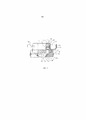
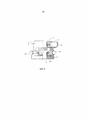
На Фиг. 1 изображен вид сбоку первого варианта осуществления держателя троакара, в соответствии с настоящим изобретением, причем, данный вид показан частично в поперечном сечении.In FIG. 1 is a side view of a first embodiment of a trocar holder in accordance with the present invention, moreover, this view is shown partially in cross section.
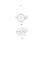
Фиг. 2 иллюстрирует вид сверху варианта осуществления, изображенного на Фиг. 1.FIG. 2 illustrates a top view of the embodiment of FIG. 1.
Фиг. 3 иллюстрирует вид снизу варианта осуществления, изображенного на Фиг. 1.FIG. 3 illustrates a bottom view of the embodiment of FIG. 1.
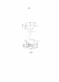
На Фиг. 4 изображен вид сбоку варианта осуществления, изображенного на Фиг. 1, который показан установленным на троакаре и в процессе работы.In FIG. 4 is a side view of the embodiment of FIG. 1, which is shown mounted on the trocar and during operation.
Фиг. 5-9 иллюстрируют виды сбоку варианта осуществления, изображенного на Фиг. 1, которые демонстрируют этапы установки на троакар.FIG. 5-9 illustrate side views of the embodiment of FIG. 1, which demonstrate installation steps on a trocar.
На Фиг. 10 изображен вид сбоку второго варианта осуществления держателя троакара, в соответствии с настоящим изобретением, причем, данный вид показан частично в поперечном сечении.In FIG. 10 is a side view of a second embodiment of a trocar holder in accordance with the present invention, moreover, this view is shown partially in cross section.
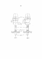
На Фиг. 11 и 12 изображены виды сбоку третьего варианта осуществления держателя троакара, в соответствии с настоящим изобретением.In FIG. 11 and 12 are side views of a third embodiment of a trocar holder in accordance with the present invention.
На чертежах одинаковыми цифрами ссылок обозначены соответствующие детали на различных чертежах.In the drawings, the same reference numerals denote the corresponding parts in various drawings.
Подробное описаниеDetailed description
Фиг. 1-9 иллюстрируют держатель 10 троакара для присоединения к троакару 12, чтобы удерживать тубус 11 троакара 12 во время проникновения тубуса 11 сквозь стенку 13 тела пациента.FIG. 1-9 illustrate a
Указанный держатель 10 включает в себя элемент 14 упора, имеющий такую форму, чтобы помещаться на наружной поверхности тубуса троакара. Указанный элемент упора образует манжету 14А, которая окружает указанный тубус с помощью уравновешивающего зажима 14В, приводимого в действие вручную, для разъемного соединения с тубусом 11, для смещения в продольном направлении по тубусу 11 троакара для расположения в выбранном положении 11А, как изображено на Фиг. 4.The specified
Держатель 10 включает в себя надувную манжету 15 для размещения на тубусе 11 троакара в требуемом положении 15В, находящемся на расстоянии от элемента 14 упора в положении 11А. Указанная надувная манжета может быть накачана с помощью источника текучей среды, обычно, воздуха или другого газа, посредством насоса 17, до заданного размера через подающую трубку 16.The
Как изображено на Фиг. 9, надувная манжета в сдутом состоянии может быть помещена на тубус троакара сквозь разрез в стенке тела и может быть накачана после введения с помощью насоса 17 через трубку 16 до надутого состояния, изображенного на Фиг.4 в положении 15В, для вхождения в контакт с внутренней поверхностью стенки 13 тела. Указанный элемент упора может быть смещен в положение 11А, для того чтобы удерживать стенку 13 тела между элементом 14 упора и надувной манжетой 15.As shown in FIG. 9, the inflatable cuff in the deflated state can be placed on the trocar tube through an incision in the body wall and can be inflated after being introduced by
Источник текучей среды, обеспечиваемый насосом 17, размещается на держателе троакара и, в частности, на элементе 14 упора, тем самым, опираясь на нее. Насос 17 включает в себя кнопку 17А, нажимаемую вручную, которая проходит внутрь цилиндра 17В, чтобы направить отмеренный объем текучей среды к надувной манжете. Указанная кнопка 17А имеет фиксатор (не показан), который удерживает ее в нажатом состоянии, для поддерживания накачивания, пока не потребуется извлечение, вследствие чего указанный фиксатор может быть разблокирован путем дальнейшего нажатия на кнопку 17А, чтобы дать возможность пружине 17С вытолкнуть кнопку и извлечь текучую среду из манжеты 15.The fluid source provided by the
Источник текучей среды, следовательно, представляет собой насосный механизм, образующий часть держателя троакара и приводимый в действие вручную. Источник 17 текучей среды обеспечивает фиксированный объем, позволяющий накачивание манжеты 15 лишь до заданного размера.The fluid source, therefore, is a pumping mechanism forming part of the trocar holder and manually actuated. The
Трубка 16 имеет круглое поперечное сечение или, в некоторых случаях, уплощенное поперечное сечение, чтобы прилегать к тубусу троакара, и обернута спирально вокруг тубуса троакара. Таким образом, она может лежать в виде сжатых в ряд витков, как изображено в исходном положении на Фиг. 1, и может растягиваться аксиально, как изображено на Фиг. 9.
Надувная манжета 15 включает в себя участок 15А тубуса, отходящий вниз от нижнего края манжеты, который может быть развернут по тубусу троакара, как изображено на Фиг. 4. в исходном положении, изображенном на Фиг. 1, манжета и указанный участок свернуты внутрь конструкции для последующего развертывания.The
Как изображено на Фиг. 1, надувная манжета 15 и элемент 14 упора образуют общий участок 10 манжеты, который можно зацеплять с тубусом 11 троакара и сдвигать аксиально вдоль него от нижнего вводимого конца до требуемого положения по длине тубуса троакара. Для того чтобы поддерживать устройство в сборе в неподвижном и неизменном состоянии для размещения на троакаре, предусматривается поддерживающая манжета 19, которая окружает надувную манжету 15, прикрепленную к элементу 14 упора, и смещается вместе с ней по тубусу троакара. Указанная поддерживающая муфта включает в себя манжету 19А с полой внутренней частью 19В, которая образует выступ 19С, на который опирается манжета 15. Это удерживает указанную манжету на месте, защищает ее и помогает поддерживать ее стерильность посредством устранения необходимости дотрагиваться до надувной манжеты, пока устройство устанавливается на место. поддерживающая манжета 19 выполнена с возможностью удаления в аксиальном направлении с элемента упора и надувной манжеты, в сторону конца троакара 11, когда надувная манжета 15 достигает своего требуемого аксиального положения, как изображено на Фиг. 8. поддерживающая манжета 19 включает в себя приводимый в действие вручную размыкающий элемент 19С, 19D для расцепления поддерживающей манжеты 19 и надувной манжеты 15. Этим управляет рычаг 19D, удерживающий манжету 15 на месте, пока не потребуется расцепление, вследствие которого элемент 19С, приводимый в действие вручную, задействуется для разблокировки указанного рычага и для того, чтобы позволить манжете 15 развернуться и затем манжете 19 смещаться аксиально в сторону от манжеты 15. как изображено на Фиг. 3, элемент 19С может образовывать кулачок с выступами 19Е, который фиксирует рычаг 19D до тех пор, пока указанные выступы не повернутся вокруг продольной оси 19F, освобождая рычаг и давая манжете 15 возможность развернуться. рычаг 19D может быть нагружен пружиной, которая гарантирует, что указанный рычаг при размыкании повернется в сторону от надувной манжеты. В качестве альтернативы кулачковой конструкции, описываемой выше, элемент 19С может представлять собой нажимную кнопку, приводимую в действие вручную, которая фиксирует рычаг 19D при однократном нажатии и освобождает указанный рычаг при повторном нажатии. При нажатии, данная кнопка имеет фиксатор, который удерживает ее в нажатом состоянии. Указанный фиксатор деблокируется при дальнейшем нажатии на кнопку, чтобы она могла быть вытолкнута пружиной.As shown in FIG. 1, the
поддерживающая манжета 19 отливается из пластикового материала, чтобы обладать жесткостью для защиты надувной манжеты, и содержит защитное покрытие 19G с одной стороны, образующее крышку для охватывания кнопки 17А, приводимой в действие вручную, насоса 17.the
Элемент 14 упора может смещаться аксиально вдоль надувной манжеты 15, когда последняя достигает своего требуемого аксиального положения 15В, при том что трубка 16 продолжается вдоль тубуса троакара по мере того, как элемент упора отодвигается от надувной манжеты.The
Как изображено на Фиг. 10, на поддерживающей манжете 19 предусматривается, при необходимости, устройство 19S, приводимое в действие вручную с помощью кнопки 19R, для воздействия на надувную манжету 15 в требуемом аксиальном положении 15В на троакаре, чтобы удерживать надувную манжету 15 от аксиального смещения в требуемом положении 15В на тубусе троакара. Данное устройство 19S может работать с использованием множества различных технических приемов, как описывается ниже, для того чтобы гарантировать, что манжета 15 останется в требуемом положении, до тех пор пока накачивание не будет обеспечивать это более эффективно.As shown in FIG. 10, a
Дополнительное внимание может потребоваться в отношении некоторых конструкций, для обеспечения того, что нижняя надувная манжета остается на месте после наложения устройства на троакар, и пока троакар введен в разрез в стенке тела пациента. таким образом, например, следующие дополнительные конструкции могут использоваться в качестве устройства 19S, приводимого в действие вручную:Additional attention may be required with some designs to ensure that the inflatable cuff remains in place after the device is placed on the trocar and while the trocar is inserted into the incision in the wall of the patient. thus, for example, the following additional structures can be used as the manually actuated
Участок материала навитой металлической пружины может быть встроен внутрь или размещен на нижней манжете надувного упора. При введении троакара, указанная пружина вынужденно раскрывается, заставляя надувной упор захватывать стенку оболочки троакара.A portion of the material of the wound metal spring can be embedded inside or placed on the lower cuff of the inflatable stop. With the introduction of the trocar, the specified spring is forced to open, forcing the inflatable support to capture the wall of the shell of the trocar.
Круглое уплотнительное кольцо, виток или разъемное кольцо могут быть обжаты в надлежащее положение с использованием элемента обжимного инструмента, включенного в поддерживающую манжету устройства. Кулачковая система используется для прикладывания усилия к металлическим элементам, которые передают данное усилие на внешний диаметр указанных круглого уплотнительного кольца, витка или разъемного кольца, заставляя их пластически деформироваться, фиксируя надувной упор. В качестве альтернативы, резьбовая уплотняемая фитинговая система, встроенная в поддерживающую манжету, аналогичная изображенной на Фиг. 10, может использоваться для обжимания указанных уплотнительного кольца, витка или разъемного кольца в нужное положение. Имеющий резьбу нижний участок поддерживающей манжеты приводится в действие вручную путем вращения его относительно имеющего резьбу верхнего участка поддерживающей манжеты, что заставляет их смыкаться друг с другом и передавать усилие на внешний диаметр указанных круглого уплотнительного кольца, витка или разъемного кольца, заставляя их пластически деформироваться, фиксируя надувной элемент упора.A round o-ring, a turn or a split ring can be crimped to the proper position using a crimping tool element included in the support sleeve of the device. The cam system is used to apply force to the metal elements that transmit this force to the outer diameter of the indicated round o-ring, coil or split ring, causing them to deform plastically, fixing the inflatable stop. Alternatively, a threaded sealed fitting system integrated in a support sleeve similar to that shown in FIG. 10 can be used to crimp said o-ring, coil or split ring to the desired position. The threaded lower portion of the supporting cuff is manually actuated by rotating it relative to the threaded upper portion of the supporting cuff, which causes them to close together and transmit force to the outer diameter of said round o-ring, coil or split ring, causing them to deform plastically, fixing inflatable stop element.
Поддерживающая манжета устройства может иметь такую конструкцию, чтобы удерживать виток пружины/разъемное кольцо открытым, пока троакар не будет введен в требуемое положение. Затем виток пружины/разъемное кольцо освобождаются путем прикладывания усилия пружины к нижней манжете надувного элемента упора, фиксируя ее на тубусе троакара.The support cuff of the device may be designed to keep the coil of spring / split ring open until the trocar is inserted into the desired position. Then the coil of the spring / split ring is released by applying the force of the spring to the lower cuff of the inflatable stop element, fixing it on the tube of the trocar.
Внутренний диаметр эластичной манжеты надувного упора может иметь адгезивную поверхность, находящуюся под защитным покрытием до готовности к использованию. Съемная поддерживающая манжета устройства имеет такую конструкцию, чтобы удерживать надувную манжету в растянутом открытом состоянии. Как только адгезив обнажается и троакар размещается в нужное положение, надувная манжета освобождается.The inner diameter of the elastic cuff of the inflatable stop may have an adhesive surface that is under a protective coating until ready for use. The removable support cuff of the device is designed to hold the inflatable cuff in a stretched open state. As soon as the adhesive is exposed and the trocar is placed in the desired position, the inflatable cuff is released.
поддерживающая манжета устройства может иметь такую конструкцию, чтобы подтягивать встроенную тонкую проволоку или ленту, прикрепленную к нижней манжете надувного элемента упора.the support cuff of the device may be designed to pull up the embedded thin wire or tape attached to the lower cuff of the inflatable stop element.
В дополнение, конструкция, описываемая в данном документе, может быть модифицирована в виде ряда альтернативных конструкций и вариантов, которые могут быть использованы следующим образом:In addition, the design described herein can be modified as a series of alternative designs and variations that can be used as follows:
Цилиндр подачи текучей среды может быть заменен камерой, заполненной текучей средой, которая сжимается с помощью элемента, управляемого вручную;The fluid supply cylinder may be replaced by a chamber filled with a fluid that is compressed by a manually operated member;
Накачивание баллона поможет дополнительно зафиксировать надувную манжету к тубусу троакара, как было указано выше;Inflating the balloon will help to additionally fix the inflatable cuff to the tube of the trocar, as described above;
Спиральный канал подачи текучей среды, охватывающий тубус троакара, может быть сформирован в виде овала или ленты, для обеспечения возможности повышенной скорости потока текучей среды при меньшем общем наружном диаметре при обматывании вокруг троакара;A spiral fluid supply channel spanning a trocar tube may be formed in the form of an oval or ribbon to allow for increased fluid flow rate with a smaller overall outer diameter when wrapped around the trocar;
канал подачи текучей среды, соединяющий верхнюю и нижнюю элементы упора, может располагаться вертикально вдоль оси троакара, при том что излишняя длина указанного канала остается незафиксированной, поскольку верхний упор смещается в направлении нижнего упора.the fluid supply channel connecting the upper and lower stop elements can be located vertically along the axis of the trocar, while the excessive length of the specified channel remains unsecured, since the upper stop is displaced in the direction of the lower stop.
Другим вариантом является случай, когда верхний упор содержит механизм самостоятельного втягивания излишней длины канала подачи текучей среды по мере того, как верхний упор смещается в направлении нижнего упора.Another option is the case where the upper stop contains a mechanism for self-retracting the excessive length of the fluid supply channel as the upper stop is displaced in the direction of the lower stop.
Более крупные троакары требуют более значительного надувного участка и, следовательно, им нужно большее количество текучей среды для выполнения накачивания. Для удовлетворения данного требования, может быть предусмотрен дополнительный цилиндр или камера подачи текучей среды на противоположной стороне относительно уже имеющегося запаса текучей среды, при необходимости;Larger trocars require a larger inflatable section and therefore need a larger amount of fluid to perform pumping. To satisfy this requirement, an additional cylinder or fluid supply chamber may be provided on the opposite side with respect to the existing fluid supply, if necessary;
Другой подход состоит в том, чтобы применять самораскрывающуюся камеру подачи текучей среды, которая обворачивается вокруг части троакара (внутри верхнего упора) и имеет достаточный объем для того, чтобы полностью накачать нижний участок при полном сжатии. Это закрытая система, содержащая указанную камеру, канал подачи текучей среды и нижний надувной участок;Another approach is to use a self-opening fluid supply chamber that wraps around a portion of the trocar (inside the upper stop) and has sufficient volume to fully inflate the lower portion when fully compressed. This is a closed system containing the specified chamber, the fluid supply channel and the lower inflatable section;
Другим вариантом является использование ручного многотактного насоса с перепускным клапаном для предотвращения чрезмерного накачивания и индикатором для того, чтобы показывать, когда нижний участок полностью накачан и полностью сдут. Тогда указанный насос переключается на обратную работу для выкачивания;Another option is to use a manual multi-stroke pump with an overflow valve to prevent over-inflation and an indicator to indicate when the lower section is fully inflated and fully deflated. Then the specified pump switches to reverse operation for pumping;
Другой вариант может предусматриваться, в котором также применяется система доставки текучей среды, но отсутствует система втягивания канала подачи текучей среды в верхнем упоре. В данном случае, верхний запас текучей среды находится в зафиксированном положении с проксимального конца тубуса троакара, но другая манжета, которая перемещается вдоль оси тубуса троакара, становится верхний упором. Канал подачи текучей среды все время полностью развернут и удерживается на месте вдоль наружной поверхности тубуса троакара с помощью оболочки.Another option may be provided in which a fluid delivery system is also used, but there is no system for retracting a fluid supply channel in the upper stop. In this case, the upper fluid supply is in a fixed position from the proximal end of the trocar tube, but the other cuff, which moves along the axis of the trocar tube, becomes the upper stop. The fluid supply channel is fully deployed all the time and is held in place along the outer surface of the trocar tube using a sheath.
рычажный механизм, изображенный в верхней части верхнего упора, используется для фиксации указанного верхнего упора на троакаре посредством манжеты, которая сжимается вокруг троакара. Альтернативой является замена данного механизма на элемент нажимной кнопки для большего удобства использования. Указанная кнопка расположена на окружности верхнем элементе упора точно так же, как иллюстрируется накачивающий насос. Нажатием данной кнопки прикладывается давление к стенке тубуса троакара, таким образом, фиксируя его.the lever mechanism depicted in the upper part of the upper stop is used to fix the specified upper stop on the trocar by means of a cuff that is compressed around the trocar. An alternative is to replace this mechanism with a push button element for greater ease of use. The indicated button is located on the circumference of the upper stop element in the same way as the inflation pump is illustrated. By pressing this button, pressure is applied to the wall of the tube of the trocar, thus fixing it.
Устройство также может устанавливаться на тубус троакара вручную, посредством только руки, без использования поддерживающей манжеты. Троакар вводится внутрь устройства, и надувная манжета натягивается вдоль оси тубуса троакара и разворачивается на тубусе троакара рукой в желательное положение.The device can also be installed on the trocar tube manually, using only the hand, without using a support cuff. The trocar is inserted into the device, and the inflatable cuff is pulled along the axis of the trocar tube and unfolds on the trocar tube with the hand in the desired position.
Может быть предложена другая идея троакара, которая в значительной мере отличается по форме, но также использует систему доставки текучей среды фиксированного объема. Указанная система доставки текучей среды фиксируется в нужном положении с проксимального конца тубуса троакара и накачивает ребра или кольца по длине тубуса троакара, когда он оказывается в требуемом положении. указанные кольца также могут состоять из твердотельных элементов, которые приводятся в действие пневматически, чтобы выступать из стенки тубуса троакара, и удаляются, когда тубус троакара подлежит извлечению. В другой конструкции может иметься устройство управления, под управлением которого указанные кольца накачиваются или приводятся в действие. в таком случае, верхний или нижний элемент упора отсутствует.Another trocar idea may be proposed that is significantly different in form, but also uses a fixed volume fluid delivery system. The fluid delivery system is fixed in position from the proximal end of the trocar tube and inflates ribs or rings along the length of the trocar tube when it is in the desired position. said rings may also consist of solid elements that are pneumatically actuated to protrude from the wall of the trocar tube and are removed when the trocar tube is to be removed. In another design, there may be a control device, under the control of which these rings are pumped or actuated. in this case, there is no upper or lower stop element.
Также является возможным прикрепить надувной элемент упора на троакар без необходимости его закатывания. В таком случае, существуют три варианта конструкции:It is also possible to attach the inflatable stop element to the trocar without the need to roll it. In this case, there are three design options:
а) Поддерживающая манжета устройства может иметь такую конструкцию, при которой передний край развернутого надувного элемента упора удерживается в открытом состоянии, до тех пор пока троакар не помещается в нужное положение. Троакар затем вталкивается внутрь отверстия и проталкивается до расположения в желательном месте. когда троакар оказывается в нужном положении, отверстие освобождается.a) The supporting cuff of the device may be designed in such a way that the front edge of the deployed inflatable stop element is held open until the trocar is placed in the desired position. The trocar is then pushed into the hole and pushed to the desired location. when the trocar is in the desired position, the hole is released.
b) Поддерживающая манжета устройства имеет средство для поддержания всего развернутого надувного элемента упора целиком в открытом состоянии, пока троакар не помещается в нужное положение. Затем надувной элемент упора освобождается, фиксируясь в нужном положении на тубусе троакара.b) The supporting cuff of the device has means for maintaining the entire deployed inflatable stop element in its entirety open, until the trocar is placed in the desired position. Then the inflatable stop element is released, fixing in the right position on the tube of the trocar.
с) Одноразовая трубчатая рама используется для того, чтобы удерживать надувной элемент упора в открытом состоянии, пока троакар не помещается в нужное положение. когда троакар оказывается в необходимом положении, указанная одноразовая рама удаляется, оставляя надувной элемент упора на внешнем диаметре тубуса троакара. Это достигается с помощью или без помощи поддерживающей манжеты устройства. при использовании поддерживающей манжеты, указанная рама сцепляется с поддерживающей манжетой. Если поддерживающая манжета не применяется, рама сцепляется с самим устройством либо в основании верхнему элементу упора, либо через каналы, содержащиеся в пределах внутреннего диаметра верхнего элемента упора.c) A disposable tubular frame is used to hold the inflatable stop element open until the trocar is placed in the desired position. when the trocar is in the required position, the indicated disposable frame is removed, leaving the inflatable stop element on the outer diameter of the trocar tube. This is achieved with or without the aid of a cuff-supporting device. when using a support cuff, said frame engages with a support cuff. If a support cuff is not used, the frame engages with the device itself either at the base of the upper stop element or through channels contained within the inner diameter of the upper stop element.
На Фиг. 11 и 12 изображены виды сбоку третьего варианта осуществления держателя троакара, в соответствии с настоящим изобретением, где держатель троакара является неотъемлемой частью самого троакара.In FIG. 11 and 12 are side views of a third embodiment of a trocar holder, in accordance with the present invention, where the trocar holder is an integral part of the trocar itself.
В данном случае также, отдельная надувная манжета отсутствует, но вместо этого сам троакар имеет ряд надувных колец.In this case, also, there is no separate inflatable cuff, but instead the trocar itself has a number of inflatable rings.
Следовательно, Фиг. 11 и 12 иллюстрируют, соответственно, троакар 100 со стержнем 102 троакара, имеющим кончик 105 для введения через разрез в стенке 106 тела пациента. указанный стержень троакара имеет ряд сформированных на внешней стенке колец 101, которые могут проходить кольцеобразно вокруг стержня или по спирали вдоль стержня и действовать для размещения стержня троакара внутри разреза. Как описывается выше, предусматривается упор 103 на конце стержня для зацепления с внешней стенкой 106, в котором указанный упор содержит ручной насос 104 для накачивания колец 101. Следовательно, как описывается выше, источник текучей среды располагается на устройстве держателя троакара, для того чтобы опираться на него, обеспечивает насосный механизм, образующий часть держателя троакара и приводимый в действие вручную, и источник текучей среды обеспечивает фиксированный объем, который позволяет накачивание только до установленного размера.Therefore, FIG. 11 and 12 respectively illustrate a
Данная конструкция является более удобной для введения и извлечения ее хирургом из тела пациента, чем традиционные конструкции данного типа, где выступы имеют фактически крупную резьбу и тубус троакара должен ввинчиваться и вывинчиваться из разреза и фасции. вращательное движение при введении и извлечении традиционного троакара с резьбой может травмировать фасцию. Описанная конструкция предназначена контактировать с самой фасцией после введения, таким образом, предотвращая потенциальное повреждение фасции от вращательного движения.This design is more convenient for the surgeon to insert and remove from the patient’s body than traditional designs of this type, where the protrusions have actually large threads and the trocar tube must be screwed in and out of the incision and fascia. rotational movement during insertion and extraction of a traditional threaded trocar can injure the fascia. The described construction is intended to contact the fascia itself after insertion, thereby preventing potential damage to the fascia from rotational movement.
В настоящей конструкции накачивание производится посредством надувающего ручного насоса вышеописанного типа, который опирается на деталь манжеты самого троакара. Этим управляется количество применяемой текучей среды и устраняется необходимость в отдельном источнике текучей среды.In this design, inflation is carried out by means of an inflating hand pump of the type described above, which relies on the cuff part of the trocar itself. This controls the amount of fluid used and eliminates the need for a separate fluid source.
Claims (16)
Applications Claiming Priority (2)
| Application Number | Priority Date | Filing Date | Title |
|---|---|---|---|
| US201161524470P | 2011-08-17 | 2011-08-17 | |
| US61/524,470 | 2011-08-17 |
Related Parent Applications (1)
| Application Number | Title | Priority Date | Filing Date |
|---|---|---|---|
| RU2014110051A Division RU2608628C2 (en) | 2011-08-17 | 2012-08-10 | Trocar support |
Publications (3)
| Publication Number | Publication Date |
|---|---|
| RU2017101659A RU2017101659A (en) | 2018-12-19 |
| RU2017101659A3 RU2017101659A3 (en) | 2020-03-13 |
| RU2721297C2 true RU2721297C2 (en) | 2020-05-18 |
Family
ID=47715518
Family Applications (2)
| Application Number | Title | Priority Date | Filing Date |
|---|---|---|---|
| RU2017101659A RU2721297C2 (en) | 2011-08-17 | 2012-08-10 | Holder of trocar |
| RU2014110051A RU2608628C2 (en) | 2011-08-17 | 2012-08-10 | Trocar support |
Family Applications After (1)
| Application Number | Title | Priority Date | Filing Date |
|---|---|---|---|
| RU2014110051A RU2608628C2 (en) | 2011-08-17 | 2012-08-10 | Trocar support |
Country Status (14)
| Country | Link |
|---|---|
| US (2) | US9681887B2 (en) |
| EP (2) | EP2744428B1 (en) |
| JP (2) | JP6138784B2 (en) |
| KR (1) | KR101996103B1 (en) |
| CN (2) | CN106236206B (en) |
| AU (1) | AU2012297530B2 (en) |
| BR (3) | BR112014003660B1 (en) |
| CA (3) | CA3048514C (en) |
| ES (2) | ES2731359T3 (en) |
| IL (1) | IL230990B (en) |
| MX (3) | MX360745B (en) |
| RU (2) | RU2721297C2 (en) |
| TR (1) | TR201908875T4 (en) |
| WO (1) | WO2013023293A2 (en) |
Families Citing this family (15)
| Publication number | Priority date | Publication date | Assignee | Title |
|---|---|---|---|---|
| BR112014003660B1 (en) | 2011-08-17 | 2021-05-25 | Surgical Stabilization Technologies Inc. | Trocar support apparatus for use with a trocar separate from the apparatus to hold the trocar in a fixed position on a patient's body wall |
| GB2529651B (en) * | 2014-08-27 | 2018-07-11 | Medishield Bv | Detachable anchor for guiding tool of minimally invasive surgery |
| AU2014415585B2 (en) * | 2014-12-31 | 2018-12-20 | Halliburton Energy Services Inc. | Improving geosteering inversion using look-ahead look-around electromagnetic tool |
| US9681889B1 (en) * | 2015-06-09 | 2017-06-20 | Surgentec, Llc | Depth controlled needle assembly |
| KR102641748B1 (en) * | 2015-11-17 | 2024-02-29 | 서지칼 스테빌라이제이션 테크놀로지스 잉크 | Trocar support |
| US11006941B2 (en) | 2016-01-29 | 2021-05-18 | Boston Scientific Limited | Access device having an anchoring feature and methods of using the same |
| US10485582B2 (en) * | 2016-07-22 | 2019-11-26 | Intuitive Surgical Operations, Inc. | Cannulas having body wall retention features, and related systems and methods |
| KR102055767B1 (en) * | 2016-11-30 | 2019-12-13 | 배경철 | Trocar |
| US11357540B2 (en) | 2018-02-16 | 2022-06-14 | Covidien Lp | Port fixation device |
| RU183470U1 (en) * | 2018-04-11 | 2018-09-24 | Андрей Викторович Сигаев | Device for holding fixed urethral catheters into the bladder with trocar cystostomy |
| US11357542B2 (en) | 2019-06-21 | 2022-06-14 | Covidien Lp | Valve assembly and retainer for surgical access assembly |
| CN111938772B (en) * | 2020-08-17 | 2021-08-06 | 广州保瑞医疗技术有限公司 | Hollow tube assembly for medical puncture outfit comprising film tube and skeleton tube |
| WO2022099137A1 (en) * | 2020-11-09 | 2022-05-12 | ClearCam Inc. | Devices, methods, and apparatuses for mitigating insufflation gas leakage from a trocar |
| RU207999U1 (en) * | 2021-09-13 | 2021-11-29 | Александр Александрович Соколов | ADJUSTABLE RETAINER FOR LAPAROSCOPIC TROCARS |
| WO2024062473A1 (en) * | 2022-09-23 | 2024-03-28 | T.A.G. Medical Products Corporation Ltd. | Trocar assembly |
Citations (4)
| Publication number | Priority date | Publication date | Assignee | Title |
|---|---|---|---|---|
| RU2221505C2 (en) * | 2000-06-07 | 2004-01-20 | Ившин Владислав Геннадьевич | Device for transcutaneously draining cavitary formations |
| WO2007109700A2 (en) * | 2006-03-21 | 2007-09-27 | Applied Medical Resources Corporation | Cannula stabilization seal |
| EP2238924A1 (en) * | 2009-03-31 | 2010-10-13 | Tyco Healthcare Group LP | Foam port and introducer assembly |
| US7998113B2 (en) * | 2008-09-30 | 2011-08-16 | Tyco Healthcare Group Lp | Medical device having prefilled balloon |
Family Cites Families (35)
| Publication number | Priority date | Publication date | Assignee | Title |
|---|---|---|---|---|
| US3044468A (en) | 1958-12-01 | 1962-07-17 | Davol Rubber Co | Catheter having built-in inflation means |
| US3253594A (en) | 1963-07-30 | 1966-05-31 | Frank E Matthews | Peritoneal cannula |
| US4861334A (en) | 1988-06-24 | 1989-08-29 | Nawaz Arain | Self-retaining gastrostomy tube |
| US5002557A (en) * | 1989-04-06 | 1991-03-26 | Hasson Harrith M | Laparoscopic cannula |
| US5176697A (en) | 1989-04-06 | 1993-01-05 | Hasson Harrith M | Laparoscopic cannula |
| CA2052310A1 (en) | 1990-10-09 | 1992-04-10 | Thomas L. Foster | Surgical access sheath |
| US5147316A (en) * | 1990-11-19 | 1992-09-15 | Castillenti Thomas A | Laparoscopic trocar with self-locking port sleeve |
| US5728119A (en) | 1991-05-29 | 1998-03-17 | Origin Medsystems, Inc. | Method and inflatable chamber apparatus for separating layers of tissue |
| JP3391449B2 (en) | 1991-08-01 | 2003-03-31 | ヒクソン・インターナショナル・ピー・エル・シー | Preservatives for wood and other cellulosic materials |
| US5338302A (en) | 1993-05-03 | 1994-08-16 | Hasson Harrith M | Vaginal stabilizer cannula |
| US5366478A (en) * | 1993-07-27 | 1994-11-22 | Ethicon, Inc. | Endoscopic surgical sealing device |
| US5697946A (en) * | 1994-10-07 | 1997-12-16 | Origin Medsystems, Inc. | Method and apparatus for anchoring laparoscopic instruments |
| US5957888A (en) * | 1995-10-10 | 1999-09-28 | United States Surgical Corporation | Surgical cannula having a variable length |
| ES2270604T3 (en) | 1998-06-25 | 2007-04-01 | C.R. Bard, Inc. | MEDICAL DEVICE WITH ELASTOMERO BALL. |
| ES2349685T3 (en) | 2001-05-31 | 2011-01-10 | Tyco Healthcare Group Lp | BALLOON CANNULA WITH EXCENTRIC GRIP. |
| US20050165432A1 (en) * | 2002-05-09 | 2005-07-28 | Russell Heinrich | Adjustable balloon anchoring trocar |
| EP1545324B1 (en) | 2002-10-04 | 2009-06-03 | Tyco Healthcare Group Lp | Balloon dissector with cannula |
| US20040111061A1 (en) | 2002-11-12 | 2004-06-10 | Diana Curran | Trocar having an inflatable cuff for maintaining an insufflated abdominal cavity during an open laparaoscopy procedure |
| CA2541850A1 (en) | 2003-10-15 | 2005-04-28 | Tyco Healthcare Group Lp | Method of joining materials |
| RU2269316C1 (en) * | 2004-09-09 | 2006-02-10 | Кондратьев Александр Владимирович | Endosurgical obturator for keeping instruments |
| US20060079922A1 (en) | 2004-10-12 | 2006-04-13 | Brian Creston | Balloon anchored surgical apparatus, its use and manufacture |
| US7597688B1 (en) * | 2004-12-27 | 2009-10-06 | Masson Marcos V | Cannula apparatus with inflatable seal and adjustable length |
| US8147453B2 (en) * | 2006-03-13 | 2012-04-03 | Applied Medical Resources Corporation | Balloon trocar |
| US8287503B2 (en) | 2006-03-13 | 2012-10-16 | Applied Medical Resources Corporation | Balloon trocar |
| WO2009111430A1 (en) | 2008-03-03 | 2009-09-11 | Applied Medical Resources Corporation | Balloon trocar advanced fixation |
| US20100010449A1 (en) | 2008-07-09 | 2010-01-14 | Kyphon Sarl | Cannula Stabilization Device, System, And Method Of Use |
| US20100081994A1 (en) | 2008-10-01 | 2010-04-01 | David Leslie Zisow | Self Retaining Laparoscopic Trocar System-Zisow Trocar Sleeve System |
| US8048027B2 (en) * | 2008-12-11 | 2011-11-01 | Tyco Healthcare Group Lp | Trocar entry incorporating an airbag |
| CN201312951Y (en) * | 2008-12-18 | 2009-09-23 | 苏州大学 | Laparoscope puncture cannula |
| CN201572081U (en) * | 2009-12-23 | 2010-09-08 | 郭秀琪 | Special cannula for non-blind area laparoscope |
| CN201624745U (en) * | 2010-02-04 | 2010-11-10 | 张士更 | Novel laparoscope puncture casing |
| US20110196205A1 (en) * | 2010-02-05 | 2011-08-11 | Tyco Healthcare Group Lp | Surgical portal locking system |
| CN101843518B (en) * | 2010-06-07 | 2011-10-05 | 常州威克医疗器械有限公司 | Disposable puncture device |
| BR112014003660B1 (en) * | 2011-08-17 | 2021-05-25 | Surgical Stabilization Technologies Inc. | Trocar support apparatus for use with a trocar separate from the apparatus to hold the trocar in a fixed position on a patient's body wall |
| US8888692B1 (en) | 2011-08-26 | 2014-11-18 | Applied Medical Resources Corporation | Trocar cannula assembly and method of manufacture |
-
2012
- 2012-08-10 BR BR112014003660-8A patent/BR112014003660B1/en active IP Right Grant
- 2012-08-10 RU RU2017101659A patent/RU2721297C2/en active
- 2012-08-10 BR BR122021000783-7A patent/BR122021000783B1/en active IP Right Grant
- 2012-08-10 JP JP2014525269A patent/JP6138784B2/en active Active
- 2012-08-10 RU RU2014110051A patent/RU2608628C2/en active
- 2012-08-10 ES ES17155777T patent/ES2731359T3/en active Active
- 2012-08-10 MX MX2017011891A patent/MX360745B/en unknown
- 2012-08-10 CN CN201610710940.9A patent/CN106236206B/en active Active
- 2012-08-10 MX MX2018009883A patent/MX364014B/en unknown
- 2012-08-10 EP EP12824427.4A patent/EP2744428B1/en active Active
- 2012-08-10 MX MX2014001868A patent/MX353204B/en active IP Right Grant
- 2012-08-10 BR BR122021000786-1A patent/BR122021000786B1/en active IP Right Grant
- 2012-08-10 ES ES12824427.4T patent/ES2636775T3/en active Active
- 2012-08-10 CA CA3048514A patent/CA3048514C/en active Active
- 2012-08-10 TR TR2019/08875T patent/TR201908875T4/en unknown
- 2012-08-10 AU AU2012297530A patent/AU2012297530B2/en active Active
- 2012-08-10 CN CN201280040150.4A patent/CN103917179B/en active Active
- 2012-08-10 CA CA2845401A patent/CA2845401C/en active Active
- 2012-08-10 CA CA3011997A patent/CA3011997C/en active Active
- 2012-08-10 EP EP17155777.0A patent/EP3195819B1/en active Active
- 2012-08-10 KR KR1020147006772A patent/KR101996103B1/en active IP Right Grant
- 2012-08-10 WO PCT/CA2012/050546 patent/WO2013023293A2/en active Application Filing
- 2012-08-10 US US14/239,006 patent/US9681887B2/en active Active
-
2014
- 2014-02-16 IL IL230990A patent/IL230990B/en active IP Right Grant
-
2017
- 2017-02-28 JP JP2017037761A patent/JP6399566B2/en active Active
- 2017-04-20 US US15/492,696 patent/US10166043B2/en active Active
Patent Citations (4)
| Publication number | Priority date | Publication date | Assignee | Title |
|---|---|---|---|---|
| RU2221505C2 (en) * | 2000-06-07 | 2004-01-20 | Ившин Владислав Геннадьевич | Device for transcutaneously draining cavitary formations |
| WO2007109700A2 (en) * | 2006-03-21 | 2007-09-27 | Applied Medical Resources Corporation | Cannula stabilization seal |
| US7998113B2 (en) * | 2008-09-30 | 2011-08-16 | Tyco Healthcare Group Lp | Medical device having prefilled balloon |
| EP2238924A1 (en) * | 2009-03-31 | 2010-10-13 | Tyco Healthcare Group LP | Foam port and introducer assembly |
Also Published As
Similar Documents
| Publication | Publication Date | Title |
|---|---|---|
| RU2721297C2 (en) | Holder of trocar | |
| ES2966168T3 (en) | trocar holder | |
| US20150216529A1 (en) | Normalization and stabilization of balloon surfaces for deflation |