RU2702829C2 - Method of natural gas flow liquefaction and nitrogen removal therefrom and device (embodiments) for implementation thereof - Google Patents
Method of natural gas flow liquefaction and nitrogen removal therefrom and device (embodiments) for implementation thereof Download PDFInfo
- Publication number
- RU2702829C2 RU2702829C2 RU2015114715A RU2015114715A RU2702829C2 RU 2702829 C2 RU2702829 C2 RU 2702829C2 RU 2015114715 A RU2015114715 A RU 2015114715A RU 2015114715 A RU2015114715 A RU 2015114715A RU 2702829 C2 RU2702829 C2 RU 2702829C2
- Authority
- RU
- Russia
- Prior art keywords
- stream
- heat exchanger
- natural gas
- nitrogen
- main heat
- Prior art date
Links
- IJGRMHOSHXDMSA-UHFFFAOYSA-N Atomic nitrogen Chemical compound N#N IJGRMHOSHXDMSA-UHFFFAOYSA-N 0.000 title claims abstract description 573
- VNWKTOKETHGBQD-UHFFFAOYSA-N methane Chemical compound C VNWKTOKETHGBQD-UHFFFAOYSA-N 0.000 title claims abstract description 518
- 229910052757 nitrogen Inorganic materials 0.000 title claims abstract description 286
- 239000003345 natural gas Substances 0.000 title claims abstract description 241
- 238000000034 method Methods 0.000 title claims abstract description 90
- 239000003949 liquefied natural gas Substances 0.000 claims abstract description 212
- 238000001816 cooling Methods 0.000 claims abstract description 152
- 238000004821 distillation Methods 0.000 claims abstract description 122
- 238000000926 separation method Methods 0.000 claims abstract description 36
- 239000007789 gas Substances 0.000 claims abstract description 27
- 238000003973 irrigation Methods 0.000 claims abstract description 18
- 230000002262 irrigation Effects 0.000 claims abstract description 18
- 239000003507 refrigerant Substances 0.000 claims description 98
- 239000007788 liquid Substances 0.000 claims description 54
- 238000001704 evaporation Methods 0.000 claims description 45
- 239000007791 liquid phase Substances 0.000 claims description 24
- 239000012808 vapor phase Substances 0.000 claims description 23
- 238000010438 heat treatment Methods 0.000 claims description 22
- 230000015572 biosynthetic process Effects 0.000 claims description 19
- 238000009434 installation Methods 0.000 claims description 13
- 230000008020 evaporation Effects 0.000 claims description 10
- 239000000203 mixture Substances 0.000 claims description 10
- 238000004891 communication Methods 0.000 claims description 8
- 239000012530 fluid Substances 0.000 claims description 8
- 238000007599 discharging Methods 0.000 claims description 4
- 239000002826 coolant Substances 0.000 abstract 1
- 230000000694 effects Effects 0.000 abstract 1
- 239000000126 substance Substances 0.000 abstract 1
- 229960005419 nitrogen Drugs 0.000 description 250
- 238000003860 storage Methods 0.000 description 21
- 239000012071 phase Substances 0.000 description 20
- ATUOYWHBWRKTHZ-UHFFFAOYSA-N Propane Chemical compound CCC ATUOYWHBWRKTHZ-UHFFFAOYSA-N 0.000 description 8
- 238000003795 desorption Methods 0.000 description 6
- 229930195733 hydrocarbon Natural products 0.000 description 5
- 150000002430 hydrocarbons Chemical class 0.000 description 5
- XLYOFNOQVPJJNP-UHFFFAOYSA-N water Substances O XLYOFNOQVPJJNP-UHFFFAOYSA-N 0.000 description 5
- 241000196324 Embryophyta Species 0.000 description 4
- 238000009835 boiling Methods 0.000 description 4
- 238000009833 condensation Methods 0.000 description 4
- 230000005494 condensation Effects 0.000 description 4
- 238000007710 freezing Methods 0.000 description 4
- 230000008014 freezing Effects 0.000 description 4
- 239000002737 fuel gas Substances 0.000 description 4
- 239000001294 propane Substances 0.000 description 4
- 239000002253 acid Substances 0.000 description 3
- 229910001873 dinitrogen Inorganic materials 0.000 description 3
- QSHDDOUJBYECFT-UHFFFAOYSA-N mercury Chemical compound [Hg] QSHDDOUJBYECFT-UHFFFAOYSA-N 0.000 description 3
- 229910052753 mercury Inorganic materials 0.000 description 3
- 238000012546 transfer Methods 0.000 description 3
- 230000008016 vaporization Effects 0.000 description 3
- CURLTUGMZLYLDI-UHFFFAOYSA-N Carbon dioxide Chemical compound O=C=O CURLTUGMZLYLDI-UHFFFAOYSA-N 0.000 description 2
- 238000010586 diagram Methods 0.000 description 2
- 230000007613 environmental effect Effects 0.000 description 2
- 239000000446 fuel Substances 0.000 description 2
- 230000014509 gene expression Effects 0.000 description 2
- 239000001307 helium Substances 0.000 description 2
- 229910052734 helium Inorganic materials 0.000 description 2
- SWQJXJOGLNCZEY-UHFFFAOYSA-N helium atom Chemical compound [He] SWQJXJOGLNCZEY-UHFFFAOYSA-N 0.000 description 2
- QWTDNUCVQCZILF-UHFFFAOYSA-N isopentane Chemical compound CCC(C)C QWTDNUCVQCZILF-UHFFFAOYSA-N 0.000 description 2
- QJGQUHMNIGDVPM-UHFFFAOYSA-N nitrogen group Chemical group [N] QJGQUHMNIGDVPM-UHFFFAOYSA-N 0.000 description 2
- 230000000630 rising effect Effects 0.000 description 2
- 239000004215 Carbon black (E152) Substances 0.000 description 1
- OTMSDBZUPAUEDD-UHFFFAOYSA-N Ethane Chemical compound CC OTMSDBZUPAUEDD-UHFFFAOYSA-N 0.000 description 1
- 241000183024 Populus tremula Species 0.000 description 1
- 239000003570 air Substances 0.000 description 1
- 239000001273 butane Substances 0.000 description 1
- 239000001569 carbon dioxide Substances 0.000 description 1
- 229910002092 carbon dioxide Inorganic materials 0.000 description 1
- 230000003749 cleanliness Effects 0.000 description 1
- 230000000052 comparative effect Effects 0.000 description 1
- 230000007423 decrease Effects 0.000 description 1
- 230000018044 dehydration Effects 0.000 description 1
- 238000006297 dehydration reaction Methods 0.000 description 1
- 230000000994 depressogenic effect Effects 0.000 description 1
- AFABGHUZZDYHJO-UHFFFAOYSA-N dimethyl butane Natural products CCCC(C)C AFABGHUZZDYHJO-UHFFFAOYSA-N 0.000 description 1
- 230000009977 dual effect Effects 0.000 description 1
- 238000005265 energy consumption Methods 0.000 description 1
- -1 for example Substances 0.000 description 1
- 239000013505 freshwater Substances 0.000 description 1
- 239000001257 hydrogen Substances 0.000 description 1
- 229910052739 hydrogen Inorganic materials 0.000 description 1
- 150000002431 hydrogen Chemical class 0.000 description 1
- 238000004519 manufacturing process Methods 0.000 description 1
- 230000004048 modification Effects 0.000 description 1
- 238000012986 modification Methods 0.000 description 1
- IJDNQMDRQITEOD-UHFFFAOYSA-N n-butane Chemical compound CCCC IJDNQMDRQITEOD-UHFFFAOYSA-N 0.000 description 1
- OFBQJSOFQDEBGM-UHFFFAOYSA-N n-pentane Natural products CCCCC OFBQJSOFQDEBGM-UHFFFAOYSA-N 0.000 description 1
- 239000002754 natural gas substitute Substances 0.000 description 1
- 150000002829 nitrogen Chemical class 0.000 description 1
- 238000012545 processing Methods 0.000 description 1
- 239000002994 raw material Substances 0.000 description 1
- 238000011084 recovery Methods 0.000 description 1
- 238000010992 reflux Methods 0.000 description 1
- 238000005057 refrigeration Methods 0.000 description 1
- 239000013535 sea water Substances 0.000 description 1
- 238000004781 supercooling Methods 0.000 description 1
Images
Classifications
-
- F—MECHANICAL ENGINEERING; LIGHTING; HEATING; WEAPONS; BLASTING
- F25—REFRIGERATION OR COOLING; COMBINED HEATING AND REFRIGERATION SYSTEMS; HEAT PUMP SYSTEMS; MANUFACTURE OR STORAGE OF ICE; LIQUEFACTION SOLIDIFICATION OF GASES
- F25J—LIQUEFACTION, SOLIDIFICATION OR SEPARATION OF GASES OR GASEOUS OR LIQUEFIED GASEOUS MIXTURES BY PRESSURE AND COLD TREATMENT OR BY BRINGING THEM INTO THE SUPERCRITICAL STATE
- F25J1/00—Processes or apparatus for liquefying or solidifying gases or gaseous mixtures
- F25J1/0002—Processes or apparatus for liquefying or solidifying gases or gaseous mixtures characterised by the fluid to be liquefied
- F25J1/0022—Hydrocarbons, e.g. natural gas
- F25J1/0025—Boil-off gases "BOG" from storages
-
- F—MECHANICAL ENGINEERING; LIGHTING; HEATING; WEAPONS; BLASTING
- F25—REFRIGERATION OR COOLING; COMBINED HEATING AND REFRIGERATION SYSTEMS; HEAT PUMP SYSTEMS; MANUFACTURE OR STORAGE OF ICE; LIQUEFACTION SOLIDIFICATION OF GASES
- F25J—LIQUEFACTION, SOLIDIFICATION OR SEPARATION OF GASES OR GASEOUS OR LIQUEFIED GASEOUS MIXTURES BY PRESSURE AND COLD TREATMENT OR BY BRINGING THEM INTO THE SUPERCRITICAL STATE
- F25J1/00—Processes or apparatus for liquefying or solidifying gases or gaseous mixtures
- F25J1/003—Processes or apparatus for liquefying or solidifying gases or gaseous mixtures characterised by the kind of cold generation within the liquefaction unit for compensating heat leaks and liquid production
- F25J1/0032—Processes or apparatus for liquefying or solidifying gases or gaseous mixtures characterised by the kind of cold generation within the liquefaction unit for compensating heat leaks and liquid production using the feed stream itself or separated fractions from it, i.e. "internal refrigeration"
- F25J1/0042—Processes or apparatus for liquefying or solidifying gases or gaseous mixtures characterised by the kind of cold generation within the liquefaction unit for compensating heat leaks and liquid production using the feed stream itself or separated fractions from it, i.e. "internal refrigeration" by liquid expansion with extraction of work
-
- F—MECHANICAL ENGINEERING; LIGHTING; HEATING; WEAPONS; BLASTING
- F25—REFRIGERATION OR COOLING; COMBINED HEATING AND REFRIGERATION SYSTEMS; HEAT PUMP SYSTEMS; MANUFACTURE OR STORAGE OF ICE; LIQUEFACTION SOLIDIFICATION OF GASES
- F25J—LIQUEFACTION, SOLIDIFICATION OR SEPARATION OF GASES OR GASEOUS OR LIQUEFIED GASEOUS MIXTURES BY PRESSURE AND COLD TREATMENT OR BY BRINGING THEM INTO THE SUPERCRITICAL STATE
- F25J1/00—Processes or apparatus for liquefying or solidifying gases or gaseous mixtures
- F25J1/003—Processes or apparatus for liquefying or solidifying gases or gaseous mixtures characterised by the kind of cold generation within the liquefaction unit for compensating heat leaks and liquid production
- F25J1/0047—Processes or apparatus for liquefying or solidifying gases or gaseous mixtures characterised by the kind of cold generation within the liquefaction unit for compensating heat leaks and liquid production using an "external" refrigerant stream in a closed vapor compression cycle
- F25J1/0052—Processes or apparatus for liquefying or solidifying gases or gaseous mixtures characterised by the kind of cold generation within the liquefaction unit for compensating heat leaks and liquid production using an "external" refrigerant stream in a closed vapor compression cycle by vaporising a liquid refrigerant stream
- F25J1/0055—Processes or apparatus for liquefying or solidifying gases or gaseous mixtures characterised by the kind of cold generation within the liquefaction unit for compensating heat leaks and liquid production using an "external" refrigerant stream in a closed vapor compression cycle by vaporising a liquid refrigerant stream originating from an incorporated cascade
-
- F—MECHANICAL ENGINEERING; LIGHTING; HEATING; WEAPONS; BLASTING
- F25—REFRIGERATION OR COOLING; COMBINED HEATING AND REFRIGERATION SYSTEMS; HEAT PUMP SYSTEMS; MANUFACTURE OR STORAGE OF ICE; LIQUEFACTION SOLIDIFICATION OF GASES
- F25J—LIQUEFACTION, SOLIDIFICATION OR SEPARATION OF GASES OR GASEOUS OR LIQUEFIED GASEOUS MIXTURES BY PRESSURE AND COLD TREATMENT OR BY BRINGING THEM INTO THE SUPERCRITICAL STATE
- F25J1/00—Processes or apparatus for liquefying or solidifying gases or gaseous mixtures
- F25J1/02—Processes or apparatus for liquefying or solidifying gases or gaseous mixtures requiring the use of refrigeration, e.g. of helium or hydrogen ; Details and kind of the refrigeration system used; Integration with other units or processes; Controlling aspects of the process
- F25J1/0211—Processes or apparatus for liquefying or solidifying gases or gaseous mixtures requiring the use of refrigeration, e.g. of helium or hydrogen ; Details and kind of the refrigeration system used; Integration with other units or processes; Controlling aspects of the process using a multi-component refrigerant [MCR] fluid in a closed vapor compression cycle
- F25J1/0212—Processes or apparatus for liquefying or solidifying gases or gaseous mixtures requiring the use of refrigeration, e.g. of helium or hydrogen ; Details and kind of the refrigeration system used; Integration with other units or processes; Controlling aspects of the process using a multi-component refrigerant [MCR] fluid in a closed vapor compression cycle as a single flow MCR cycle
-
- F—MECHANICAL ENGINEERING; LIGHTING; HEATING; WEAPONS; BLASTING
- F25—REFRIGERATION OR COOLING; COMBINED HEATING AND REFRIGERATION SYSTEMS; HEAT PUMP SYSTEMS; MANUFACTURE OR STORAGE OF ICE; LIQUEFACTION SOLIDIFICATION OF GASES
- F25J—LIQUEFACTION, SOLIDIFICATION OR SEPARATION OF GASES OR GASEOUS OR LIQUEFIED GASEOUS MIXTURES BY PRESSURE AND COLD TREATMENT OR BY BRINGING THEM INTO THE SUPERCRITICAL STATE
- F25J1/00—Processes or apparatus for liquefying or solidifying gases or gaseous mixtures
- F25J1/02—Processes or apparatus for liquefying or solidifying gases or gaseous mixtures requiring the use of refrigeration, e.g. of helium or hydrogen ; Details and kind of the refrigeration system used; Integration with other units or processes; Controlling aspects of the process
- F25J1/0228—Coupling of the liquefaction unit to other units or processes, so-called integrated processes
- F25J1/0235—Heat exchange integration
- F25J1/0237—Heat exchange integration integrating refrigeration provided for liquefaction and purification/treatment of the gas to be liquefied, e.g. heavy hydrocarbon removal from natural gas
- F25J1/0238—Purification or treatment step is integrated within one refrigeration cycle only, i.e. the same or single refrigeration cycle provides feed gas cooling (if present) and overhead gas cooling
-
- F—MECHANICAL ENGINEERING; LIGHTING; HEATING; WEAPONS; BLASTING
- F25—REFRIGERATION OR COOLING; COMBINED HEATING AND REFRIGERATION SYSTEMS; HEAT PUMP SYSTEMS; MANUFACTURE OR STORAGE OF ICE; LIQUEFACTION SOLIDIFICATION OF GASES
- F25J—LIQUEFACTION, SOLIDIFICATION OR SEPARATION OF GASES OR GASEOUS OR LIQUEFIED GASEOUS MIXTURES BY PRESSURE AND COLD TREATMENT OR BY BRINGING THEM INTO THE SUPERCRITICAL STATE
- F25J3/00—Processes or apparatus for separating the constituents of gaseous or liquefied gaseous mixtures involving the use of liquefaction or solidification
- F25J3/02—Processes or apparatus for separating the constituents of gaseous or liquefied gaseous mixtures involving the use of liquefaction or solidification by rectification, i.e. by continuous interchange of heat and material between a vapour stream and a liquid stream
- F25J3/0204—Processes or apparatus for separating the constituents of gaseous or liquefied gaseous mixtures involving the use of liquefaction or solidification by rectification, i.e. by continuous interchange of heat and material between a vapour stream and a liquid stream characterised by the feed stream
- F25J3/0209—Natural gas or substitute natural gas
-
- F—MECHANICAL ENGINEERING; LIGHTING; HEATING; WEAPONS; BLASTING
- F25—REFRIGERATION OR COOLING; COMBINED HEATING AND REFRIGERATION SYSTEMS; HEAT PUMP SYSTEMS; MANUFACTURE OR STORAGE OF ICE; LIQUEFACTION SOLIDIFICATION OF GASES
- F25J—LIQUEFACTION, SOLIDIFICATION OR SEPARATION OF GASES OR GASEOUS OR LIQUEFIED GASEOUS MIXTURES BY PRESSURE AND COLD TREATMENT OR BY BRINGING THEM INTO THE SUPERCRITICAL STATE
- F25J3/00—Processes or apparatus for separating the constituents of gaseous or liquefied gaseous mixtures involving the use of liquefaction or solidification
- F25J3/02—Processes or apparatus for separating the constituents of gaseous or liquefied gaseous mixtures involving the use of liquefaction or solidification by rectification, i.e. by continuous interchange of heat and material between a vapour stream and a liquid stream
- F25J3/0228—Processes or apparatus for separating the constituents of gaseous or liquefied gaseous mixtures involving the use of liquefaction or solidification by rectification, i.e. by continuous interchange of heat and material between a vapour stream and a liquid stream characterised by the separated product stream
- F25J3/0233—Processes or apparatus for separating the constituents of gaseous or liquefied gaseous mixtures involving the use of liquefaction or solidification by rectification, i.e. by continuous interchange of heat and material between a vapour stream and a liquid stream characterised by the separated product stream separation of CnHm with 1 carbon atom or more
-
- F—MECHANICAL ENGINEERING; LIGHTING; HEATING; WEAPONS; BLASTING
- F25—REFRIGERATION OR COOLING; COMBINED HEATING AND REFRIGERATION SYSTEMS; HEAT PUMP SYSTEMS; MANUFACTURE OR STORAGE OF ICE; LIQUEFACTION SOLIDIFICATION OF GASES
- F25J—LIQUEFACTION, SOLIDIFICATION OR SEPARATION OF GASES OR GASEOUS OR LIQUEFIED GASEOUS MIXTURES BY PRESSURE AND COLD TREATMENT OR BY BRINGING THEM INTO THE SUPERCRITICAL STATE
- F25J3/00—Processes or apparatus for separating the constituents of gaseous or liquefied gaseous mixtures involving the use of liquefaction or solidification
- F25J3/02—Processes or apparatus for separating the constituents of gaseous or liquefied gaseous mixtures involving the use of liquefaction or solidification by rectification, i.e. by continuous interchange of heat and material between a vapour stream and a liquid stream
- F25J3/0228—Processes or apparatus for separating the constituents of gaseous or liquefied gaseous mixtures involving the use of liquefaction or solidification by rectification, i.e. by continuous interchange of heat and material between a vapour stream and a liquid stream characterised by the separated product stream
- F25J3/0257—Processes or apparatus for separating the constituents of gaseous or liquefied gaseous mixtures involving the use of liquefaction or solidification by rectification, i.e. by continuous interchange of heat and material between a vapour stream and a liquid stream characterised by the separated product stream separation of nitrogen
-
- F—MECHANICAL ENGINEERING; LIGHTING; HEATING; WEAPONS; BLASTING
- F25—REFRIGERATION OR COOLING; COMBINED HEATING AND REFRIGERATION SYSTEMS; HEAT PUMP SYSTEMS; MANUFACTURE OR STORAGE OF ICE; LIQUEFACTION SOLIDIFICATION OF GASES
- F25J—LIQUEFACTION, SOLIDIFICATION OR SEPARATION OF GASES OR GASEOUS OR LIQUEFIED GASEOUS MIXTURES BY PRESSURE AND COLD TREATMENT OR BY BRINGING THEM INTO THE SUPERCRITICAL STATE
- F25J2200/00—Processes or apparatus using separation by rectification
- F25J2200/02—Processes or apparatus using separation by rectification in a single pressure main column system
-
- F—MECHANICAL ENGINEERING; LIGHTING; HEATING; WEAPONS; BLASTING
- F25—REFRIGERATION OR COOLING; COMBINED HEATING AND REFRIGERATION SYSTEMS; HEAT PUMP SYSTEMS; MANUFACTURE OR STORAGE OF ICE; LIQUEFACTION SOLIDIFICATION OF GASES
- F25J—LIQUEFACTION, SOLIDIFICATION OR SEPARATION OF GASES OR GASEOUS OR LIQUEFIED GASEOUS MIXTURES BY PRESSURE AND COLD TREATMENT OR BY BRINGING THEM INTO THE SUPERCRITICAL STATE
- F25J2200/00—Processes or apparatus using separation by rectification
- F25J2200/76—Refluxing the column with condensed overhead gas being cycled in a quasi-closed loop refrigeration cycle
-
- F—MECHANICAL ENGINEERING; LIGHTING; HEATING; WEAPONS; BLASTING
- F25—REFRIGERATION OR COOLING; COMBINED HEATING AND REFRIGERATION SYSTEMS; HEAT PUMP SYSTEMS; MANUFACTURE OR STORAGE OF ICE; LIQUEFACTION SOLIDIFICATION OF GASES
- F25J—LIQUEFACTION, SOLIDIFICATION OR SEPARATION OF GASES OR GASEOUS OR LIQUEFIED GASEOUS MIXTURES BY PRESSURE AND COLD TREATMENT OR BY BRINGING THEM INTO THE SUPERCRITICAL STATE
- F25J2205/00—Processes or apparatus using other separation and/or other processing means
- F25J2205/02—Processes or apparatus using other separation and/or other processing means using simple phase separation in a vessel or drum
- F25J2205/04—Processes or apparatus using other separation and/or other processing means using simple phase separation in a vessel or drum in the feed line, i.e. upstream of the fractionation step
-
- F—MECHANICAL ENGINEERING; LIGHTING; HEATING; WEAPONS; BLASTING
- F25—REFRIGERATION OR COOLING; COMBINED HEATING AND REFRIGERATION SYSTEMS; HEAT PUMP SYSTEMS; MANUFACTURE OR STORAGE OF ICE; LIQUEFACTION SOLIDIFICATION OF GASES
- F25J—LIQUEFACTION, SOLIDIFICATION OR SEPARATION OF GASES OR GASEOUS OR LIQUEFIED GASEOUS MIXTURES BY PRESSURE AND COLD TREATMENT OR BY BRINGING THEM INTO THE SUPERCRITICAL STATE
- F25J2210/00—Processes characterised by the type or other details of the feed stream
- F25J2210/90—Boil-off gas from storage
-
- F—MECHANICAL ENGINEERING; LIGHTING; HEATING; WEAPONS; BLASTING
- F25—REFRIGERATION OR COOLING; COMBINED HEATING AND REFRIGERATION SYSTEMS; HEAT PUMP SYSTEMS; MANUFACTURE OR STORAGE OF ICE; LIQUEFACTION SOLIDIFICATION OF GASES
- F25J—LIQUEFACTION, SOLIDIFICATION OR SEPARATION OF GASES OR GASEOUS OR LIQUEFIED GASEOUS MIXTURES BY PRESSURE AND COLD TREATMENT OR BY BRINGING THEM INTO THE SUPERCRITICAL STATE
- F25J2215/00—Processes characterised by the type or other details of the product stream
- F25J2215/04—Recovery of liquid products
-
- F—MECHANICAL ENGINEERING; LIGHTING; HEATING; WEAPONS; BLASTING
- F25—REFRIGERATION OR COOLING; COMBINED HEATING AND REFRIGERATION SYSTEMS; HEAT PUMP SYSTEMS; MANUFACTURE OR STORAGE OF ICE; LIQUEFACTION SOLIDIFICATION OF GASES
- F25J—LIQUEFACTION, SOLIDIFICATION OR SEPARATION OF GASES OR GASEOUS OR LIQUEFIED GASEOUS MIXTURES BY PRESSURE AND COLD TREATMENT OR BY BRINGING THEM INTO THE SUPERCRITICAL STATE
- F25J2220/00—Processes or apparatus involving steps for the removal of impurities
- F25J2220/60—Separating impurities from natural gas, e.g. mercury, cyclic hydrocarbons
- F25J2220/62—Separating low boiling components, e.g. He, H2, N2, Air
-
- F—MECHANICAL ENGINEERING; LIGHTING; HEATING; WEAPONS; BLASTING
- F25—REFRIGERATION OR COOLING; COMBINED HEATING AND REFRIGERATION SYSTEMS; HEAT PUMP SYSTEMS; MANUFACTURE OR STORAGE OF ICE; LIQUEFACTION SOLIDIFICATION OF GASES
- F25J—LIQUEFACTION, SOLIDIFICATION OR SEPARATION OF GASES OR GASEOUS OR LIQUEFIED GASEOUS MIXTURES BY PRESSURE AND COLD TREATMENT OR BY BRINGING THEM INTO THE SUPERCRITICAL STATE
- F25J2230/00—Processes or apparatus involving steps for increasing the pressure of gaseous process streams
- F25J2230/08—Cold compressor, i.e. suction of the gas at cryogenic temperature and generally without afterstage-cooler
-
- F—MECHANICAL ENGINEERING; LIGHTING; HEATING; WEAPONS; BLASTING
- F25—REFRIGERATION OR COOLING; COMBINED HEATING AND REFRIGERATION SYSTEMS; HEAT PUMP SYSTEMS; MANUFACTURE OR STORAGE OF ICE; LIQUEFACTION SOLIDIFICATION OF GASES
- F25J—LIQUEFACTION, SOLIDIFICATION OR SEPARATION OF GASES OR GASEOUS OR LIQUEFIED GASEOUS MIXTURES BY PRESSURE AND COLD TREATMENT OR BY BRINGING THEM INTO THE SUPERCRITICAL STATE
- F25J2230/00—Processes or apparatus involving steps for increasing the pressure of gaseous process streams
- F25J2230/30—Compression of the feed stream
-
- F—MECHANICAL ENGINEERING; LIGHTING; HEATING; WEAPONS; BLASTING
- F25—REFRIGERATION OR COOLING; COMBINED HEATING AND REFRIGERATION SYSTEMS; HEAT PUMP SYSTEMS; MANUFACTURE OR STORAGE OF ICE; LIQUEFACTION SOLIDIFICATION OF GASES
- F25J—LIQUEFACTION, SOLIDIFICATION OR SEPARATION OF GASES OR GASEOUS OR LIQUEFIED GASEOUS MIXTURES BY PRESSURE AND COLD TREATMENT OR BY BRINGING THEM INTO THE SUPERCRITICAL STATE
- F25J2240/00—Processes or apparatus involving steps for expanding of process streams
- F25J2240/30—Dynamic liquid or hydraulic expansion with extraction of work, e.g. single phase or two-phase turbine
-
- F—MECHANICAL ENGINEERING; LIGHTING; HEATING; WEAPONS; BLASTING
- F25—REFRIGERATION OR COOLING; COMBINED HEATING AND REFRIGERATION SYSTEMS; HEAT PUMP SYSTEMS; MANUFACTURE OR STORAGE OF ICE; LIQUEFACTION SOLIDIFICATION OF GASES
- F25J—LIQUEFACTION, SOLIDIFICATION OR SEPARATION OF GASES OR GASEOUS OR LIQUEFIED GASEOUS MIXTURES BY PRESSURE AND COLD TREATMENT OR BY BRINGING THEM INTO THE SUPERCRITICAL STATE
- F25J2245/00—Processes or apparatus involving steps for recycling of process streams
- F25J2245/90—Processes or apparatus involving steps for recycling of process streams the recycled stream being boil-off gas from storage
-
- F—MECHANICAL ENGINEERING; LIGHTING; HEATING; WEAPONS; BLASTING
- F25—REFRIGERATION OR COOLING; COMBINED HEATING AND REFRIGERATION SYSTEMS; HEAT PUMP SYSTEMS; MANUFACTURE OR STORAGE OF ICE; LIQUEFACTION SOLIDIFICATION OF GASES
- F25J—LIQUEFACTION, SOLIDIFICATION OR SEPARATION OF GASES OR GASEOUS OR LIQUEFIED GASEOUS MIXTURES BY PRESSURE AND COLD TREATMENT OR BY BRINGING THEM INTO THE SUPERCRITICAL STATE
- F25J2270/00—Refrigeration techniques used
- F25J2270/18—External refrigeration with incorporated cascade loop
-
- F—MECHANICAL ENGINEERING; LIGHTING; HEATING; WEAPONS; BLASTING
- F25—REFRIGERATION OR COOLING; COMBINED HEATING AND REFRIGERATION SYSTEMS; HEAT PUMP SYSTEMS; MANUFACTURE OR STORAGE OF ICE; LIQUEFACTION SOLIDIFICATION OF GASES
- F25J—LIQUEFACTION, SOLIDIFICATION OR SEPARATION OF GASES OR GASEOUS OR LIQUEFIED GASEOUS MIXTURES BY PRESSURE AND COLD TREATMENT OR BY BRINGING THEM INTO THE SUPERCRITICAL STATE
- F25J2270/00—Refrigeration techniques used
- F25J2270/66—Closed external refrigeration cycle with multi component refrigerant [MCR], e.g. mixture of hydrocarbons
Landscapes
- Engineering & Computer Science (AREA)
- Physics & Mathematics (AREA)
- Mechanical Engineering (AREA)
- Thermal Sciences (AREA)
- General Engineering & Computer Science (AREA)
- Chemical & Material Sciences (AREA)
- Oil, Petroleum & Natural Gas (AREA)
- Chemical Kinetics & Catalysis (AREA)
- General Chemical & Material Sciences (AREA)
- Separation By Low-Temperature Treatments (AREA)
Abstract
Description
Уровень техникиState of the art
[0001] Настоящее изобретение относится к способу сжижения сырьевого потока природного газа и удаления из него азота. Настоящее изобретение также относится к установке (такой как, например, установка сжижения природного газа или другой вид технологического оборудования) для сжижения сырьевого потока природного газа и удаления из него азота.[0001] The present invention relates to a method for liquefying a natural gas feed stream and removing nitrogen therefrom. The present invention also relates to a plant (such as, for example, a natural gas liquefaction plant or other type of processing equipment) for liquefying a feed stream of natural gas and removing nitrogen from it.
[0002] В способах сжижения природного газа часто желательно или необходимо, например, из-за требований к чистоте и/или получению, удалять азот из сырьевого потока при сведении к минимуму потерь продукта (метана). Удаляемый азотный продукт может использоваться в качестве топливного газа или сбрасываться в атмосферу. При использовании в качестве топливного газа азотный продукт должен содержать достаточное количество метана (обычно >30 мол. %) для сохранения своей теплотворной способности. В этом случае отделение азота не так трудно из-за нестрогих требований к чистоте азотного продукта, и задачей является выбор наиболее эффективного способа с минимальным дополнительным оборудованием и энергопотреблением. Однако, во многих установках сжиженного природного газа (СПГ) малого и среднего масштаба, которые приводятся в действие электродвигателями, существует очень небольшая потребность в топливном газе, и азотный продукт должен сбрасываться в атмосферу. При сбросе азотный продукт должен соответствовать строгим требованиям к чистоте (например, >95 мол. % или >99 мол. %), из-за экологических соображений и/или в связи с требованиями к извлечению метана. Эти требования к чистоте создают трудности при отделении. В случае очень высокой концентрации азота (как правило, более 10 мол. %, в некоторых случаях до 20 мол. % или даже выше) в подаваемом сырье природного газа применение специальной установки удаления азота (NRU) оказывается надежным способом для эффективного удаления азота и получения чистого (>99 мол. %) азотного продукта. В большинстве случаев, однако, природный газ содержит примерно от 1 мол. % до 10 мол. % азота. Когда концентрация азота в подаваемом сырье находится в пределах этого диапазона, применимость NRU будет затруднена высокими капитальными затратами из-за сложности дополнительного оборудования. Ряд документов известного уровня техники предлагает альтернативные решения для удаления азота из природного газа, включающие добавление рециркуляционного потока азота в NRU или использование специальной ректификационной колонны. Однако, эти способы часто очень сложны, требуют большого количества оборудования (что связано с капитальными затратами), сложны в эксплуатации и/или неэффективны, особенно для сырьевых потоков с пониженными концентрациями азота (<5 мол. %). Кроме того, часто бывает, что концентрация азота в подаваемом сырье природного газа будет меняться время от времени, что означает, что, даже при работе с сырьем, которое в настоящее время имеет высокие содержания азота, нельзя гарантировать, что это будет сохраняться во всех случаях. Поэтому было бы желательно разработать способ, который является простым, рентабельным и способным эффективно удалять азот из подаваемого сырья природного газа при низких концентрациях азота.[0002] In natural gas liquefaction processes, it is often desirable or necessary, for example, due to purity and / or production requirements, to remove nitrogen from the feed stream while minimizing product (methane) losses. The removed nitrogen product can be used as fuel gas or discharged into the atmosphere. When used as fuel gas, the nitrogen product should contain a sufficient amount of methane (usually> 30 mol%) to maintain its calorific value. In this case, the separation of nitrogen is not so difficult due to the stringent requirements for the purity of the nitrogen product, and the task is to choose the most efficient method with minimal additional equipment and energy consumption. However, in many small and medium scale liquefied natural gas (LNG) plants that are driven by electric motors, there is very little need for fuel gas and the nitrogen product must be discharged into the atmosphere. When discharged, the nitrogen product must meet strict purity requirements (e.g.> 95 mol% or> 99 mol%), due to environmental considerations and / or in connection with methane recovery requirements. These cleanliness requirements make separation difficult. In the case of a very high nitrogen concentration (usually more than 10 mol%, in some cases up to 20 mol% or even higher) in the feed of natural gas, the use of a special nitrogen removal unit (NRU) is a reliable way to effectively remove nitrogen and obtain pure (> 99 mol%) nitrogen product. In most cases, however, natural gas contains from about 1 mol. % to 10 mol. % nitrogen. When the nitrogen concentration in the feed is within this range, the applicability of the NRU will be hindered by high capital costs due to the complexity of the additional equipment. A number of prior art documents provide alternative solutions for removing nitrogen from natural gas, including adding a recirculated nitrogen stream to the NRU or using a special distillation column. However, these methods are often very complex, require a large amount of equipment (which is associated with capital costs), are difficult to operate and / or inefficient, especially for feed streams with low nitrogen concentrations (<5 mol%). In addition, it often happens that the concentration of nitrogen in the supplied natural gas feed will change from time to time, which means that even when working with feed that currently has high nitrogen contents, it cannot be guaranteed that this will be maintained in all cases . Therefore, it would be desirable to develop a method that is simple, cost-effective, and capable of effectively removing nitrogen from the feed gas of natural gas at low nitrogen concentrations.
[0003] В US 3721099 описан способ сжижения природного газа и отделения азота от сжиженного природного газа с помощью ректификации. В этом способе подаваемое сырье природного газа предварительно охлаждается и частично сжижается в серии теплообменников и разделяется в фазовом сепараторе на жидкую и парообразную фазы. Парообразный поток природного газа далее сжижается и переохлаждается в трубчатом змеевике в нижней части колонны двойной ректификации, обеспечивая паровую нагрузку в колонне высокого давления. Жидкие потоки природного газа из трубчатого змеевика затем дополнительно переохлаждаются в теплообменнике, расширяются в расширительном клапане и вводятся и разделяются в колонне высокого давления. Обогащенный метаном жидкий поток, отводимый из нижней части ректификационной колонны высокого давления, и обогащенный метаном жидкий поток, полученный из фазового сепаратора, переохлаждаются в дополнительных теплообменниках, расширяются с помощью расширительного клапана, и вводятся и разделяются в колонне низкого давления. Орошение в колонне низкого давления обеспечивается потоком жидкого азота, полученным в результате сжижения в теплообменнике потока азота, полученного из верхней части колонны высокого давления. Обедненный азотом СПГ продукт (преимущественно жидкий метан), содержащий примерно 0,5% азота, получают из нижней части колонны низкого давления и направляют в резервуар для хранения СПГ. Обогащенные азотом потоки получают из верхней части колонны низкого давления (содержащие примерно 95 мол. % азота) и из верхней части колонны высокого давления. Обогащенные азотом потоки и отпарной газ из резервуара СПГ нагреваются в различных теплообменниках с обеспечением для них охлаждения.[0003] US 3,721,099 describes a process for liquefying natural gas and separating nitrogen from liquefied natural gas by distillation. In this method, the natural gas feed is pre-cooled and partially liquefied in a series of heat exchangers and separated in a phase separator into liquid and vapor phases. The vaporous stream of natural gas is then liquefied and supercooled in a tubular coil at the bottom of the double distillation column, providing a steam load in the high pressure column. The liquid natural gas flows from the tubular coil are then further subcooled in the heat exchanger, expanded in the expansion valve, and introduced and separated in the high pressure column. The methane-enriched liquid stream discharged from the bottom of the high-pressure distillation column and the methane-enriched liquid stream obtained from the phase separator are supercooled in additional heat exchangers, expanded with an expansion valve, and introduced and separated in the low-pressure column. Irrigation in the low pressure column is provided by a stream of liquid nitrogen obtained by liquefying in a heat exchanger a stream of nitrogen obtained from the upper part of the high pressure column. A nitrogen-depleted LNG product (predominantly liquid methane) containing approximately 0.5% nitrogen is obtained from the bottom of the low pressure column and sent to the LNG storage tank. Nitrogen-rich streams are obtained from the top of the low pressure column (containing about 95 mol% nitrogen) and from the top of the high pressure column. Nitrogen-rich streams and stripping gas from the LNG tank are heated in various heat exchangers to provide cooling for them.
[0004] В US 7520143 описан способ, в котором сбрасываемый поток азота, содержащий 98 мол. % азота, отделяется с помощью колонны для удаления азота. Сырьевой поток природного газа сжижается в первой (теплой) секции главного теплообменника с получением потока СПГ, который отводится из промежуточного местоположения теплообменника, расширяется в расширительном клапане и направляется в нижнюю часть колонны удаления азота. Кубовая жидкость из колонны удаления азота переохлаждается во второй (холодной) секции главного теплообменника и расширяется через клапан в испарительный барабан с получением обедненного азотом СПГ продукта (менее 1,5 мол. % азота) и обогащенного азотом потока, который имеет более низкую чистоту (30 мол. % азота), чем сбрасываемый поток азота, и который используется в качестве топливного газа. Пар головного погона из колонны удаления азота разделяется, при этом часть пара отводится в виде сбрасываемого потока азота, и остальное конденсируется в теплообменнике в испарительном барабане для обеспечения орошения колонны удаления азота. Охлаждение главного теплообменника обеспечивается замкнутой системой охлаждения, использующей смешанный хладагент.[0004] In US 7520143 describes a method in which a discharge stream of nitrogen containing 98 mol. % nitrogen, is separated using a nitrogen removal column. The natural gas feed stream is liquefied in the first (warm) section of the main heat exchanger to produce an LNG stream that is diverted from the intermediate location of the heat exchanger, expands in an expansion valve, and flows to the bottom of the nitrogen removal column. The bottom liquid from the nitrogen removal column is supercooled in the second (cold) section of the main heat exchanger and expands through the valve into the evaporation drum to obtain a nitrogen-depleted LNG product (less than 1.5 mol% of nitrogen) and a nitrogen-rich stream that has a lower purity (30 mol.% nitrogen) than the discharged stream of nitrogen, and which is used as fuel gas. The steam of the overhead from the nitrogen removal column is separated, with some of the steam being discharged in the form of a discharged nitrogen stream, and the rest is condensed in the heat exchanger in the evaporation drum to provide irrigation of the nitrogen removal column. Cooling of the main heat exchanger is provided by a closed cooling system using mixed refrigerant.
[0005] В US 2011/0041389 описан способ, несколько похожий на способ, описанный в US 7520143, в котором сбрасываемый поток азота высокой чистоты (как правило, 90-100% по объему азота) отделяется от сырьевого потока природного газа в ректификационной колонне. Сырьевой поток природного газа охлаждают в теплой секции главного теплообменника с получением охлажденного потока природного газа. Часть этого потока отводится из первого промежуточного местоположения главного теплообменника, расширяется и направляется в нижнюю часть ректификационной колонны в качестве десорбирующего газа. Остальная часть потока дополнительно охлаждается и сжижается в промежуточной секции главного теплообменника с образованием потока СПГ, который отводится из второго (более холодного) промежуточного местоположения теплообменника, расширяется и направляется в промежуточное местоположение ректификационной колонны. Кубовая жидкость из ректификационной колонны отводится в виде обедненного азотом потока СПГ, переохлаждается в холодной секции главного теплообменника и расширяется в фазовом сепараторе с получением обедненного азотом СПГ продукта и обогащенного азотом потока, который сжимают и рециркулируют обратно в сырьевой поток природного газа. Пар головного погона из ректификационной колонны разделяется, при этом часть пара отводится в виде сбрасываемого потока азота высокой чистоты, и остальное конденсируется в теплообменнике в фазовом сепараторе с обеспечением орошения для ректификационной колонны.[0005] US 2011/0041389 describes a method somewhat similar to that described in US 7520143, in which a high purity nitrogen discharged stream (typically 90-100% by volume of nitrogen) is separated from a natural gas feed stream in a distillation column. The natural gas feed stream is cooled in a warm section of the main heat exchanger to produce a cooled natural gas stream. Part of this flow is diverted from the first intermediate location of the main heat exchanger, expands and is sent to the bottom of the distillation column as a stripping gas. The remaining part of the stream is additionally cooled and liquefied in the intermediate section of the main heat exchanger with the formation of the LNG stream, which is diverted from the second (colder) intermediate location of the heat exchanger, expands and goes to the intermediate location of the distillation column. The bottom liquid from the distillation column is discharged in the form of a nitrogen-depleted LNG stream, supercooled in the cold section of the main heat exchanger and expanded in a phase separator to obtain a nitrogen-depleted LNG product and a nitrogen-enriched stream, which is compressed and recycled back to the natural gas feed stream. The steam of the overhead from the distillation column is separated, while part of the steam is discharged in the form of a high purity nitrogen stream being discharged, and the rest is condensed in a heat exchanger in a phase separator, providing irrigation for the distillation column.
[0006] В IPCOM000222164D, документе из базы данных ip.com, описан способ, в котором самостоятельная установка удаления азота (NRU) используется для получения обедненного азотом потока природного газа и сбрасываемого потока чистого азота. Сырьевой поток природного газа предварительно охлаждается и частично сжижается в теплом теплообменнике и разделяется в фазовом сепараторе на парообразный и жидкий потоки природного газа. Парообразный поток сжижается в холодном теплообменнике и направляется в верхнее или в промежуточное местоположение ректификационной колонны. Жидкий поток дополнительно охлаждается в холодном теплообменнике, отдельно от парообразного потока и параллельно с ним, и после этого направляется в промежуточное местоположение ректификационной колонны (ниже местоположения ввода парообразного потока). Паровая нагрузка ректификационной колонны обеспечивается с помощью нагревания и испарения части обедненной азотом кубовой жидкости из ректификационной колонны в холодном теплообменнике, тем самым обеспечивая также и охлаждение для устройства. Остальная часть обедненной азотом кубовой жидкости перекачивается, нагревается и испаряется в теплом теплообменнике, тем самым обеспечивая охлаждение для этого устройства, и выходит из теплого теплообменника в виде полностью испаренного парообразного потока. Обогащенный азотом пар головного погона, отведенный из ректификационной колонны, нагревается в холодном и теплом теплообменниках с обеспечением дополнительного охлаждения указанных устройств. Там, где парообразный поток вводится в промежуточное местоположение ректификационной колонны, дополнительное орошение для колонны может обеспечиваться конденсацией части пара головного погона и возвращением его в колонну. Это может осуществляться с помощью нагревания пара головного погона в теплообменнике-экономайзере, разделения нагретого пара головного погона и конденсации части нагретого пара головного погона в теплообменнике-экономайзере, и возвращения сконденсированной части в верх ректификационной колонны. В данном способе не используется внешнее охлаждение.[0006] IPCOM000222164D, a document from the ip.com database, describes a method in which a self-contained nitrogen removal unit (NRU) is used to produce a nitrogen-depleted natural gas stream and a discharged pure nitrogen stream. The natural gas feed stream is pre-cooled and partially liquefied in a warm heat exchanger and separated in a phase separator into vapor and liquid natural gas streams. The vapor stream is liquefied in a cold heat exchanger and sent to the upper or intermediate location of the distillation column. The liquid stream is additionally cooled in a cold heat exchanger, separately from the vapor stream and in parallel with it, and then sent to the intermediate location of the distillation column (below the location of the input vapor stream). The vapor load of the distillation column is provided by heating and evaporating part of the nitrogen-depleted still liquid from the distillation column in a cold heat exchanger, thereby also providing cooling for the device. The rest of the nitrogen-depleted bottoms liquid is pumped, heated and evaporated in a warm heat exchanger, thereby providing cooling for this device, and leaves the warm heat exchanger in the form of a completely vaporized vapor stream. The nitrogen-enriched overhead steam withdrawn from the distillation column is heated in cold and warm heat exchangers to provide additional cooling for these devices. Where a vapor stream is introduced into the intermediate location of the distillation column, additional irrigation for the column can be provided by condensation of part of the steam of the overhead and returning it to the column. This can be done by heating the overhead steam in the heat exchanger-economizer, separating the heated overhead steam and condensing part of the heated overhead steam in the heat exchanger-economizer, and returning the condensed part to the top of the distillation column. This method does not use external cooling.
[0007] В US 2011/0289963 описан способ, в котором колонна десорбции азота используется для отделения азота от потока природного газа. В этом способе сырьевой поток природного газа охлаждается и частично сжижается в теплой секции главного теплообменника посредством теплообмена с одним смешанным хладагентом. Частично сконденсированный природный газ отводится из главного теплообменника и разделяется в фазовом сепараторе или в дистилляционном сосуде на парообразный и жидкий потоки природного газа. Жидкий поток дополнительно охлаждается в холодной секции главного теплообменника перед расширением и введением в колонну десорбции азота. Обедненный азотом СПГ продукт (содержащий 1-3 об. % азота) отводится из нижней части десорбционной колонны, и обогащенный азотом парообразный поток (содержащий менее 10 об. % метана) отводится из верха десорбционной колонны. Парообразный поток природного газа из фазового сепаратора или дистилляционного сосуда расширяется и охлаждается в отдельных теплообменниках и вводится в верхнюю часть десорбционной колонны для обеспечения орошения. Охлаждение дополнительных теплообменников обеспечивается испарением части кубовой жидкости из десорбционной колонны (тем самым обеспечивается также и паровая нагрузка колонны) и нагреванием обогащенного азотом парообразного потока, отводимого из верха десорбционной колонны.[0007] US 2011/0289963 describes a method in which a nitrogen stripping column is used to separate nitrogen from a natural gas stream. In this method, the natural gas feed stream is cooled and partially liquefied in the warm section of the main heat exchanger by heat exchange with one mixed refrigerant. Partially condensed natural gas is removed from the main heat exchanger and is separated in a phase separator or in a distillation vessel into vapor and liquid natural gas streams. The liquid stream is further cooled in the cold section of the main heat exchanger before expansion and introduction of nitrogen into the desorption column. A nitrogen-depleted LNG product (containing 1-3 vol.% Nitrogen) is discharged from the bottom of the desorption column, and a nitrogen-rich vapor stream (containing less than 10 vol.% Methane) is discharged from the top of the desorption column. The vaporous stream of natural gas from the phase separator or distillation vessel is expanded and cooled in separate heat exchangers and introduced into the upper part of the desorption column to provide irrigation. The cooling of additional heat exchangers is provided by the evaporation of part of the bottom liquid from the desorption column (thereby also providing the steam load of the column) and by heating the vaporized stream enriched with nitrogen from the top of the desorption column.
[0008] В US 8522574 описан другой способ, в котором азот отводится из сжиженного природного газа. В этом способе сырьевой поток природного газа сначала охлаждается и сжижается в главном теплообменнике. Жидкий поток после этого охлаждается во вторичном теплообменнике и расширяется в емкости мгновенного испарения, где обогащенный азотом пар отделяется от обогащенной метаном жидкости. Парообразный поток дополнительно расширяется и поступает в верхнюю часть ректификационной колонны. Жидкий поток из емкости мгновенного испарения разделяется, при этом одна часть водится в промежуточное местоположение ректификационной колонны, и другая часть нагревается во вторичном теплообменнике и вводится в нижнюю часть ректификационной колонны. Обогащенный азотом пар головного погона, полученный из ректификационной колонны, проходит через вторичный теплообменник и нагревается в нем с обеспечением дополнительного охлаждения указанного теплообменника. Продукт сжиженного природного газа извлекают из низа ректификационной колонны.[0008] US 8522574 describes another method in which nitrogen is removed from liquefied natural gas. In this method, the natural gas feed stream is first cooled and liquefied in a main heat exchanger. The liquid stream is then cooled in a secondary heat exchanger and expands in the flash tank, where the nitrogen-enriched vapor is separated from the methane-enriched liquid. The vapor stream further expands and enters the top of the distillation column. The liquid stream from the flash tank is separated, while one part is led to an intermediate location of the distillation column, and the other part is heated in a secondary heat exchanger and introduced into the lower part of the distillation column. Nitrogen-enriched overhead steam obtained from a distillation column passes through a secondary heat exchanger and is heated in it to provide additional cooling for said heat exchanger. The liquefied natural gas product is recovered from the bottom of the distillation column.
[0009] В US 2012/019883 описан способ сжижения потока природного газа и удаления из него азота. Сырьевой поток природного газа сжижается в главном теплообменнике, расширяется и вводится в низ разделительной колонны. Охлаждение главного теплообменника обеспечивается замкнутой системой охлаждения с циркулирующим смешанным хладагентом. Обедненный азотом СПГ, отводимый из низа разделительной колонны, расширяется и далее разделяется в фазовом сепараторе. Обедненный азотом СПГ из фазового сепаратора направляется в резервуар для хранения СПГ. Парообразный поток из фазового сепаратора объединяется с отпарным газом из резервуара для хранения СПГ, нагревается в главном теплообменнике с обеспечением дополнительного охлаждения для главного теплообменника, сжимается и рециркулирует в сырьевой поток природного газа. Обогащенный азотом пар (90-100 об. % азота), отведенный из верха разделительной колонны, также нагревается в главном теплообменнике с обеспечением дополнительного охлаждения главного теплообменника.[0009] US 2012/019883 describes a method for liquefying a natural gas stream and removing nitrogen from it. The natural gas feed stream is liquefied in the main heat exchanger, expanded and introduced into the bottom of the separation column. The cooling of the main heat exchanger is provided by a closed cooling system with circulating mixed refrigerant. The nitrogen-depleted LNG discharged from the bottom of the separation column is expanded and further separated in a phase separator. LNG depleted of nitrogen from the phase separator is sent to the LNG storage tank. The vapor stream from the phase separator is combined with the stripping gas from the LNG storage tank, heated in the main heat exchanger to provide additional cooling for the main heat exchanger, compressed and recycled to the natural gas feed stream. Steam enriched with nitrogen (90-100 vol.% Nitrogen), diverted from the top of the separation column, is also heated in the main heat exchanger with additional cooling of the main heat exchanger.
Краткое изложение сущности изобретенияSummary of the invention
[0010] В соответствии с первым аспектом настоящего изобретения предлагается способ сжижения сырьевого потока природного газа и удаления из него азота, причем способ включает в себя:[0010] In accordance with a first aspect of the present invention, there is provided a method of liquefying a natural gas feed stream and removing nitrogen from it, the method including:
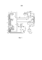
(а) пропускание сырьевого потока природного газа через главный теплообменник для охлаждения потока природного газа и сжижения всего указанного потока или его части, с образованием в результате первого потока СПГ;(a) passing a feed stream of natural gas through a main heat exchanger to cool the stream of natural gas and liquefy all or part of said stream, resulting in a first LNG stream;
(b) отведение первого потока СПГ из главного теплообменника;(b) diverting the first LNG stream from the main heat exchanger;
(с) расширение и частичное испарение сжиженного или частично сжиженного потока природного газа, и введение указанного потока в ректификационную колонну, в которой поток разделяется на парообразную и жидкую фазы, при этом сжиженный или частично сжиженный поток природного газа является первым потоком СПГ, или является по меньшей мере частично сжиженным обогащенным азотом потоком природного газа, полученным в результате отделения обогащенного азотом потока природного газа от первого потока СПГ или от сырьевого потока природного газа, и по меньшей мере частичного сжижения указанного потока в главном теплообменнике;(c) expanding and partially evaporating the liquefied or partially liquefied natural gas stream, and introducing said stream into a distillation column in which the stream is separated into vapor and liquid phases, wherein the liquefied or partially liquefied natural gas stream is the first LNG stream, or is at least partially liquefied nitrogen-rich natural gas stream obtained by separating the nitrogen-rich natural gas stream from the first LNG stream or from a natural gas feed stream, and at least partial liquefaction of said stream in the main heat exchanger;
(d) образование обогащенного азотом парообразного продукта из пара головного погона, отведенного из ректификационной колонны;(d) the formation of a nitrogen-rich vapor product from the overhead steam withdrawn from the distillation column;
(e) обеспечение орошения для ректификационной колонны с помощью конденсации части пара головного погона из ректификационной колонны в теплообменнике-конденсаторе; и(e) providing irrigation for the distillation column by condensing a portion of the overhead steam from the distillation column in a heat exchanger-condenser; and
(f) образование второго потока СПГ из кубовой жидкости, отведенной из ректификационной колонны;(f) the formation of a second stream of LNG from the bottom liquid withdrawn from the distillation column;
при этом охлаждение для главного теплообменника и для теплообменника-конденсатора обеспечивается замкнутой системой охлаждения, причем хладагент, циркулирующий по замкнутой системе охлаждения, проходит через главный теплообменник и нагревается в нем, и проходит через теплообменник-конденсатор и нагревается в нем.while cooling for the main heat exchanger and for the heat exchanger-condenser is provided by a closed cooling system, and the refrigerant circulating through the closed cooling system passes through the main heat exchanger and heats in it, and passes through the heat exchanger-condenser and heats up in it.
[0011] В соответствии со вторым аспектом настоящего изобретения предлагается установка для сжижения сырьевого потока природного газа и удаления из него азота, причем установка включает в себя:[0011] In accordance with a second aspect of the present invention, there is provided an apparatus for liquefying a feed stream of natural gas and removing nitrogen therefrom, the apparatus including:
главный теплообменник, имеющий канал охлаждения для приема сырьевого потока природного газа и пропускания сырьевого потока природного газа через теплообменник для охлаждения потока и сжижения всего потока или его части, с образованием первого потока СПГ;a main heat exchanger having a cooling channel for receiving a natural gas feed stream and passing a natural gas feed stream through a heat exchanger to cool the stream and liquefy all or part of the stream, to form a first LNG stream;
расширительное устройство и ректификационную колонну, находящиеся в сообщении по текучей среде с главным теплообменником, для приема, расширения и частичного испарения сжиженного или частично сжиженного потока природного газа и разделения указанного потока в ректификационной колонне на парообразную и жидкую фазы, при этом сжиженный или частично сжиженный поток природного газа является первым потоком СПГ, или является по меньшей мере частично сжиженным обогащенным азотом потоком природного газа, полученным в результате отделения обогащенного азотом потока природного газа от первого потока СПГ или от сырьевого потока природного газа, и по меньшей мере частичного сжижения указанного потока в главном теплообменнике;an expansion device and a distillation column in fluid communication with the main heat exchanger for receiving, expanding, and partially evaporating the liquefied or partially liquefied natural gas stream and separating said stream in the distillation column into vapor and liquid phases, while the liquefied or partially liquefied stream natural gas is the first LNG stream, or is at least partially liquefied nitrogen enriched natural gas stream resulting from the separation of both a nitrogen-gas stream of natural gas from a first LNG stream or from a feed stream of natural gas, and at least partially liquefying said stream in a main heat exchanger;
теплообменник-конденсатор для обеспечения орошения для ректификационной колонны с помощью конденсации части пара головного погона, полученного из ректификационной колонны; иa heat exchanger-condenser to provide irrigation for the distillation column by condensing part of the steam overhead obtained from the distillation column; and
замкнутую систему охлаждения для обеспечения охлаждения главного теплообменника и теплообменника-конденсатора, причем хладагент, циркулирующий по замкнутой системе охлаждения, проходит через главный теплообменник и нагревается в нем, и проходит через теплообменник-конденсатор и нагревается в нем.a closed cooling system to ensure cooling of the main heat exchanger and the heat exchanger-condenser, and the refrigerant circulating through the closed cooling system passes through the main heat exchanger and heats up in it, and passes through the heat exchanger-condenser and heats up in it.
[0012] Предпочтительные аспекты настоящего изобретения включают в себя следующие аспекты, пронумерованные от #1 до #21:[0012] Preferred aspects of the present invention include the following aspects, numbered # 1 to # 21:
#1. Способ сжижения сырьевого потока природного газа и удаления из него азота, причем способ включает в себя:#one. A method of liquefying a feed stream of natural gas and removing nitrogen from it, the method comprising:
(а) пропускание сырьевого потока природного газа через главный теплообменник для охлаждения потока природного газа и сжижения всего указанного потока или его части, с образованием в результате первого потока СПГ;(a) passing a feed stream of natural gas through a main heat exchanger to cool the stream of natural gas and liquefy all or part of said stream, resulting in a first LNG stream;
(b) отведение первого потока СПГ из главного теплообменника;(b) diverting the first LNG stream from the main heat exchanger;
(с) расширение и частичное испарение сжиженного или частично сжиженного потока природного газа, и введение указанного потока в ректификационную колонну, в которой поток разделяется на парообразную и жидкую фазы, при этом сжиженный или частично сжиженный поток природного газа является первым потоком СПГ, или является по меньшей мере частично сжиженным обогащенным азотом потоком природного газа, полученным в результате отделения обогащенного азотом потока природного газа от первого потока СПГ или от сырьевого потока природного газа, и по меньшей мере частичного сжижения указанного потока в главном теплообменнике;(c) expanding and partially evaporating the liquefied or partially liquefied natural gas stream, and introducing said stream into a distillation column in which the stream is separated into vapor and liquid phases, wherein the liquefied or partially liquefied natural gas stream is the first LNG stream, or is at least partially liquefied nitrogen-rich natural gas stream obtained by separating the nitrogen-rich natural gas stream from the first LNG stream or from a natural gas feed stream, and at least partial liquefaction of said stream in the main heat exchanger;
(d) образование обогащенного азотом парообразного продукта из пара головного погона, отведенного из ректификационной колонны;(d) the formation of a nitrogen-rich vapor product from the overhead steam withdrawn from the distillation column;
(e) обеспечение орошения для ректификационной колонны с помощью конденсации части пара головного погона из ректификационной колонны в теплообменнике-конденсаторе; и(e) providing irrigation for the distillation column by condensing a portion of the overhead steam from the distillation column in a heat exchanger-condenser; and
(f) образование второго потока СПГ из кубовой жидкости, отведенной из ректификационной колонны;(f) the formation of a second stream of LNG from the bottom liquid withdrawn from the distillation column;
при этом охлаждение для главного теплообменника и для теплообменника-конденсатора обеспечивается замкнутой системой охлаждения, причем хладагент, циркулирующий по замкнутой системе охлаждения, проходит через главный теплообменник и нагревается в нем, и проходит через теплообменник-конденсатор и нагревается в нем.while cooling for the main heat exchanger and for the heat exchanger-condenser is provided by a closed cooling system, and the refrigerant circulating through the closed cooling system passes through the main heat exchanger and heats in it, and passes through the heat exchanger-condenser and heats up in it.
#2. Способ по аспекту #1, в котором хладагент, который проходит через теплообменник-конденсатор и нагревается в нем, после этого проходит через главный теплообменник и дополнительно нагревается в нем.# 2 The method of aspect # 1, wherein the refrigerant that passes through the heat exchanger-condenser and is heated therein, then passes through the main heat exchanger and is further heated therein.
#3. Способ по аспекту #1 или #2, в котором нагретый хладагент, который получен после охлаждения, подается в главный теплообменник и в теплообменник-конденсатор, сжимается в одном или более компрессорах и охлаждается в одном или более последующем охладителе с образованием сжатого хладагента; сжатый хладагент проходит через и охлаждается в главном теплообменнике с образованием охлажденного сжатого хладагента, который отводится из главного теплообменника; и охлажденный сжатый хладагент после этого разделяется, при этом часть хладагента расширяется и возвращается непосредственно в главный теплообменник для прохождения через главный теплообменник и нагревания в нем, и другая часть хладагента расширяется и направляется в теплообменник-конденсатор для прохождения через теплообменник-конденсатор и нагревания в нем.# 3 The method according to aspect # 1 or # 2, in which the heated refrigerant that is obtained after cooling is supplied to the main heat exchanger and to the heat exchanger-condenser, is compressed in one or more compressors and cooled in one or more subsequent chillers to form compressed refrigerant; the compressed refrigerant passes through and is cooled in the main heat exchanger to form a cooled compressed refrigerant which is discharged from the main heat exchanger; and the cooled compressed refrigerant is then separated, with a portion of the refrigerant expanding and returning directly to the main heat exchanger for passage through the main heat exchanger and heating therein, and another portion of the refrigerant expanding and sent to the heat exchanger condenser for passing through the heat exchanger-condenser and heating therein .
#4. Способ по любому из аспектов #1-#3, в котором хладагент, циркулирующий по замкнутой системе охлаждения, является смешанным хладагентом.#four. The method according to any one of aspects # 1 to # 3, wherein the refrigerant circulating in a closed cooling system is a mixed refrigerant.
#5. Способ по аспекту #4, в котором нагретый смешанный хладагент, который получают после охлаждения, подается в главный теплообменник и в теплообменник-конденсатор, сжимается, охлаждается в главном теплообменнике и разделяется при охлаждении с образованием некоторого количества сжиженных или частично сжиженных потоков охлажденного хладагента различных составов, при этом поток охлажденного хладагента с максимальной концентрацией более легких компонентов, полученный из холодного конца главного теплообменника, разделяется и расширяется с образованием потока хладагента, который нагревается в теплообменнике-конденсаторе, и потока хладагента, который возвращается в холодный конец главного теплообменника для нагревания там.#5. The method according to aspect # 4, in which the heated mixed refrigerant, which is obtained after cooling, is supplied to the main heat exchanger and to the heat exchanger-condenser, is compressed, cooled in the main heat exchanger and separated during cooling to form a certain amount of liquefied or partially liquefied chilled refrigerant flows of various compositions while the flow of chilled refrigerant with a maximum concentration of lighter components obtained from the cold end of the main heat exchanger is divided and expanded with the formation of a stream of refrigerant, which is heated in the heat exchanger-condenser, and a stream of refrigerant, which returns to the cold end of the main heat exchanger for heating there.
#6. Способ по любому из аспектов #1-#5, в котором охлаждение теплообменника-конденсатора обеспечивается как замкнутой системой охлаждения, так и нагреванием пара головного погона, отведенного из ректификационной колонны.# 6 The method according to any one of aspects # 1 to # 5, wherein the cooling of the heat exchanger-condenser is provided both by a closed cooling system and by heating a steam of overhead extracted from the distillation column.
#7. Способ по аспекту #6, в котором:# 7 The method according to aspect # 6, in which:
стадия (е) включает в себя нагревание пара головного погона, отведенного из ректификационной колонны, в теплообменнике-конденсаторе, сжатие первой части нагретого пара головного погона, охлаждение и по меньшей мере частичная конденсация сжатой части в теплообменнике-конденсаторе, и расширение и повторное введение охлажденной и по меньшей мере частично сконденсированной части обратно в верх ректификационной колонны; иstage (e) includes heating the overhead steam withdrawn from the distillation column in a heat exchanger-condenser, compressing the first part of the heated overhead steam, cooling and at least partially condensing the compressed part in the heat exchanger-condenser, and expanding and reintroducing the cooled and at least partially condensed portion back to the top of the distillation column; and
стадия (d) включает в себя образование обогащенного азотом парообразного продукта из второй части нагретого пара головного погона.stage (d) includes the formation of a nitrogen-rich vaporous product from the second part of the heated steam overhead.
#8. Способ по любому из аспектов #1-#7, в котором стадия (c) включает в себя расширение и частичное испарение первого потока СПГ и введение указанного потока в ректификационную колонну для разделения потока на парообразную и жидкую фазы.#8. The method according to any one of aspects # 1 to # 7, wherein step (c) comprises expanding and partially vaporizing the first LNG stream and introducing said stream into a distillation column to separate the stream into vapor and liquid phases.
#9. Способ по аспекту #8, где способ дополнительно включает в себя направление второго СПГ потока в резервуар для хранения СПГ.#9. The method of aspect # 8, wherein the method further includes directing a second LNG stream to the LNG storage tank.
#10. Способ по любому из аспектов #1-#7, в котором стадия (c) включает в себя расширение и частичное испарение по меньшей мере частично сжиженного обогащенного азотом потока природного газа и введение указанного потока в ректификационную колонну для разделения потока на парообразную и жидкую фазы, в котором по меньшей мере частично сжиженный обогащенный азотом поток природного газа образуется в результате отделения обогащенного азотом потока природного газа от первого потока СПГ и по меньшей мере частичного сжижения указанного потока в главном теплообменнике.#10. The method according to any one of aspects # 1 to # 7, wherein step (c) comprises expanding and partially evaporating the at least partially liquefied nitrogen-rich natural gas stream and introducing said stream into a distillation column to separate the stream into vapor and liquid phases, in which at least partially liquefied nitrogen-rich natural gas stream is formed by separating the nitrogen-rich natural gas stream from the first LNG stream and at least partially liquefying said stream into m heat exchanger.
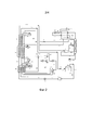
#11. Способ по аспекту #10, в котором по меньшей мере частично сжиженный обогащенный азотом поток природного газа образуются с помощью (i) расширения, частичного испарения и разделения первого потока СПГ или потока СПГ, образованного из части первого потока СПГ, с образованием обедненного азотом СПГ продукта и рециркуляционного потока, состоящего из обогащенных азотом паров природного газа, (ii) сжатия рециркуляционного потока с образованием сжатого рециркуляционного потока, и (iii) пропускания сжатого рециркуляционного потока через главный теплообменник, отдельно от сырьевого потока природного газа и параллельно с ним, для охлаждения сжатого рециркуляционного потока и по меньшей мере частичного сжижения всего потока или его части, в результате чего образуется по меньшей мере частично сжиженный обогащенный азотом поток природного газа.#eleven. The method of aspect # 10, wherein the at least partially liquefied nitrogen-rich natural gas stream is formed by (i) expanding, partially evaporating and separating the first LNG stream or LNG stream formed from part of the first LNG stream to form a nitrogen-depleted LNG product and a recycle stream consisting of nitrogen enriched natural gas vapors, (ii) compressing the recycle stream to form a compressed recycle stream, and (iii) passing the compressed recycle stream through the main heat an exchanger, separate from and parallel to the natural gas feed stream, for cooling the compressed recycle stream and at least partially liquefying the entire stream or part thereof, resulting in at least partially liquefied nitrogen-rich natural gas stream.
#12. Способ по аспекту #11, в котором первый поток СПГ или поток СПГ, образованный из части первого потока СПГ, расширяется и передается в резервуар для хранения СПГ, в котором часть СПГ испаряется, образуя, таким образом, обогащенные азотом пары природного газа и обедненный азотом СПГ продукт, и обогащенные азотом пары природного газа отводятся из резервуара с образованием рециркуляционного потока.#12. The method of aspect # 11, wherein the first LNG stream or LNG stream formed from a portion of the first LNG stream is expanded and transferred to an LNG storage tank in which a portion of the LNG is vaporized, thereby forming nitrogen enriched natural gas vapors and nitrogen depleted The LNG product and nitrogen-rich natural gas vapors are discharged from the reservoir to form a recycle stream.
#13. Способ по аспекту #11 или #12, где способ дополнительно включает в себя расширение, частичное испарение и разделение второго потока СПГ с образованием дополнительных обогащенных азотом паров природного газа для рециркуляционного потока и дополнительного обедненного азотом СПГ продукта.#13. The method according to aspect # 11 or # 12, wherein the method further includes expanding, partially evaporating and separating the second LNG stream to form additional nitrogen-rich natural gas vapors for the recycle stream and additional nitrogen-depleted LNG product.
#14. Способ по любому из аспектов #1-#7, в котором стадия (c) включает в себя расширение и частичное испарение по меньшей мере частично сжиженного обогащенного азотом потока природного газа и введение указанного потока в ректификационную колонну для разделения потока на парообразную и жидкую фазы, в котором по меньшей мере частично сжиженный обогащенный азотом поток природного газа образуется в результате отделения обогащенного азотом потока природного газа от сырьевого потока природного газа и по меньшей мере частичного сжижения указанного потока в главном теплообменнике.#fourteen. The method according to any one of aspects # 1 to # 7, wherein step (c) comprises expanding and partially vaporizing the at least partially liquefied nitrogen-rich natural gas stream and introducing said stream into a distillation column to separate the stream into vapor and liquid phases, in which at least partially liquefied nitrogen-rich natural gas stream is formed by separating the nitrogen-rich natural gas stream from the natural gas feed stream and at least partially liquefying said otok in the main heat exchanger.
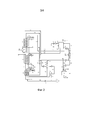
#15. Способ по аспекту #14, в котором стадия (а) включает в себя (i) введение сырьевого потока природного газа в теплый конец главного теплообменника, охлаждение и по меньшей мере частичное сжижение сырьевого потока природного газа, и отведение охлажденного и по меньшей мере частично сжиженного потока из промежуточного местоположения главного теплообменника, (ii) расширение, частичное испарение и разделение охлажденного и по меньшей мере частично сжиженного потока с образованием обогащенного азотом парообразного потока природного газа и обедненного азотом жидкого потока природного газа, и (iii) раздельное повторное введение парообразного и жидкого потоков в промежуточное местоположение главного теплообменника и параллельно дополнительное охлаждение парообразного потока и жидкого потока, при этом жидкий поток дополнительно охлаждается с образованием первого потока СПГ, и парообразный поток дополнительно охлаждается и по меньшей мере частично сжижается с образованием по меньшей мере частично сжиженного обогащенного азотом потока природного газа.#fifteen. The method according to aspect # 14, wherein step (a) comprises (i) introducing a natural gas feed stream into the warm end of the main heat exchanger, cooling and at least partially liquefying the natural gas feed stream, and discharging the cooled and at least partially liquefied a stream from an intermediate location of the main heat exchanger, (ii) expanding, partially evaporating and separating the cooled and at least partially liquefied stream to form a nitrogen-rich vapor stream of natural gas and a nitrogen stream of a natural gas stream, and (iii) separately reintroducing the vapor and liquid streams at an intermediate location of the main heat exchanger and simultaneously additionally cooling the vapor stream and the liquid stream, wherein the liquid stream is further cooled to form a first LNG stream, and the vapor stream is further cooled and at least partially liquefied to form at least partially liquefied nitrogen-rich natural gas stream.
#16. Способ по аспекту #15, где способ дополнительно включает в себя:#16. The method according to aspect # 15, where the method further includes:
(g) расширение, частичное испарение и разделение второго потока СПГ с образованием обедненного азотом СПГ продукта и рециркуляционного потока, состоящего из обогащенных азотом паров природного газа;(g) expansion, partial evaporation and separation of the second LNG stream to form a nitrogen-depleted LNG product and a recycle stream consisting of nitrogen enriched natural gas vapors;
(h) сжатие рециркуляционного потока с образованием сжатого рециркуляционного потока; и(h) compressing the recycle stream to form a compressed recycle stream; and
(i) возвращение сжатого рециркуляционного потока в главный теплообменник для охлаждения и по меньшей мере частичного сжижения вместе с сырьевым потоком природного газа или отдельно от него.(i) returning the compressed recycle stream to the main heat exchanger for cooling and at least partially liquefying with or separately from the natural gas feed stream.
#17. Способ по аспекту #16, в котором стадия (g) включает в себя расширение второго потока СПГ, транспортировку расширенного потока в резервуар для хранения СПГ, в котором часть СПГ испаряется, образуя, таким образом, обогащенные азотом пары природного газа и обедненный азотом СПГ продукт, и отведение обогащенных азотом паров природного газа из резервуара с образованием рециркуляционного потока.# 17. The method of aspect # 16, wherein step (g) comprises expanding a second LNG stream, transporting the expanded stream to an LNG storage tank in which a portion of the LNG is vaporized, thereby forming a nitrogen-rich natural gas vapor and a nitrogen-depleted LNG product and withdrawing nitrogen-rich natural gas vapors from the reservoir to form a recycle stream.
#18. Способ по аспекту #16 или #17, где способ дополнительно включает в себя расширение, частичное испарение и разделение первого потока СПГ с образованием дополнительных обогащенных азотом паров природного газа для рециркуляционного потока и дополнительного обедненного азотом СПГ продукта.#eighteen. The method according to aspect # 16 or # 17, wherein the method further includes expanding, partially evaporating and separating the first LNG stream to form additional nitrogen-rich natural gas vapors for the recycle stream and additional nitrogen-depleted LNG product.
#19. Способ по любому из аспектов #15-#18, в котором:#19. The method according to any one of aspects # 15- # 18, wherein:
стадия (a) (ii) включает в себя расширение, частичное испарение и разделение охлажденного и по меньшей мере частично сжиженного потока с образованием обогащенного азотом парообразного потока природного газа, потока десорбирующего газа, состоящего из обогащенных азотом паров природного газа, и обедненного азотом жидкого потока природного газа; иstep (a) (ii) includes expanding, partially evaporating and separating the cooled and at least partially liquefied stream to form a nitrogen-rich vapor stream of natural gas, a stripping gas stream consisting of nitrogen-rich natural gas vapors, and a nitrogen-depleted liquid stream natural gas; and
стадия (c) дополнительно включает в себя введение потока десорбирующего газа в низ ректификационной колонны.step (c) further includes introducing a stripping gas stream into the bottom of the distillation column.
#20. Способ по любому из аспектов #1-#19, в котором сжиженный или частично сжиженный поток природного газа вводится в ректификационную колонну в промежуточном местоположении колонны, и паровая нагрузка ректификационной колонны обеспечивается нагреванием и испарением части кубовой жидкости в теплообменнике-ребойлере с помощью косвенного теплообмена со сжиженным или частично сжиженным потоком природного газа перед введением указанного потока в ректификационную колонну.#twenty. The method according to any one of aspects # 1- # 19, in which a liquefied or partially liquefied natural gas stream is introduced into the distillation column at an intermediate location of the column, and the vapor load of the distillation column is provided by heating and evaporating part of the bottoms liquid in the heat exchanger-reboiler by indirect heat exchange with liquefied or partially liquefied natural gas stream before introducing the specified stream into the distillation column.
#21. Установка для сжижения сырьевого потока природного газа и удаления из него азота, причем установка включает в себя:# 21. Installation for liquefying the feed stream of natural gas and removing nitrogen from it, and the installation includes:
главный теплообменник, имеющий канал охлаждения для приема сырьевого потока природного газа и пропускания сырьевого потока природного газа через теплообменник для охлаждения потока и сжижения всего потока или его части, с образованием первого потока СПГ;a main heat exchanger having a cooling channel for receiving a natural gas feed stream and passing a natural gas feed stream through a heat exchanger to cool the stream and liquefy all or part of the stream to form a first LNG stream;
расширительное устройство и ректификационную колонну, находящиеся в сообщении по текучей среде с главным теплообменником, для приема, расширения и частичного испарения сжиженного или частично сжиженного потока природного газа и разделения указанного потока в ректификационной колонне на парообразную и жидкую фазы, при этом сжиженный или частично сжиженный поток природного газа является первым потоком СПГ, или является по меньшей мере частично сжиженным обогащенным азотом потоком природного газа, полученным в результате отделения обогащенного азотом потока природного газа от первого потока СПГ или от сырьевого потока природного газа, и по меньшей мере частичного сжижения указанного потока в главном теплообменнике;an expansion device and a distillation column in fluid communication with the main heat exchanger for receiving, expanding, and partially evaporating the liquefied or partially liquefied natural gas stream and separating said stream in the distillation column into vapor and liquid phases, while the liquefied or partially liquefied stream natural gas is the first LNG stream, or is at least partially liquefied nitrogen enriched natural gas stream resulting from the separation of both a nitrogen-gas stream of natural gas from a first LNG stream or from a feed stream of natural gas, and at least partially liquefying said stream in a main heat exchanger;
теплообменник-конденсатор для обеспечения орошения для ректификационной колонны с помощью конденсации части пара головного погона, полученного из ректификационной колонны; иa heat exchanger-condenser to provide irrigation for the distillation column by condensing part of the steam overhead obtained from the distillation column; and
замкнутую систему охлаждения для обеспечения охлаждения главного теплообменника и теплообменника-конденсатора, причем хладагент, циркулирующий по замкнутой системе охлаждения, проходит через главный теплообменник и нагревается в нем, и проходит через теплообменник-конденсатор и нагревается в нем.a closed cooling system to ensure cooling of the main heat exchanger and the heat exchanger-condenser, and the refrigerant circulating through the closed cooling system passes through the main heat exchanger and heats up in it, and passes through the heat exchanger-condenser and heats up in it.
Краткое описание чертежейBrief Description of the Drawings
[0013] На фиг. 1 представлена принципиальная технологическая схема, иллюстрирующая способ и установку для сжижения и удаления азота из потока природного газа в соответствии с одним вариантом осуществления настоящего изобретения.[0013] FIG. 1 is a schematic flowchart illustrating a method and apparatus for liquefying and removing nitrogen from a natural gas stream in accordance with one embodiment of the present invention.
[0014] На фиг. 2 представлена принципиальная технологическая схема, иллюстрирующая способ и установку в соответствии с другим вариантом осуществления настоящего изобретения.[0014] FIG. 2 is a schematic flow diagram illustrating a method and apparatus in accordance with another embodiment of the present invention.
[0015] На фиг. 3 представлена принципиальная технологическая схема, иллюстрирующая способ и установку в соответствии с еще одним вариантом осуществления настоящего изобретения.[0015] FIG. 3 is a schematic flow diagram illustrating a method and an apparatus in accordance with yet another embodiment of the present invention.
[0016] На фиг. 4 представлен график, иллюстрирующий кривые охлаждения для теплообменника-конденсатора, используемого в способе и установке, проиллюстрированных на фиг.1.[0016] FIG. 4 is a graph illustrating cooling curves for a heat exchanger-condenser used in the method and installation illustrated in FIG.
Подробное описаниеDetailed description
[0018] Как отмечалось выше, в соответствии с первым аспектом настоящего изобретения предлагается способ сжижения сырьевого потока природного газа и удаления из него азота, причем способ включает в себя:[0018] As noted above, in accordance with a first aspect of the present invention, there is provided a method of liquefying a feed stream of natural gas and removing nitrogen from it, the method comprising:
(а) пропускание сырьевого потока природного газа через главный теплообменник для охлаждения потока природного газа и сжижения (и, как правило, переохлаждения) всего указанного потока или его части, с образованием в результате первого потока СПГ;(a) passing the feed stream of natural gas through the main heat exchanger to cool the flow of natural gas and liquefy (and, as a rule, supercooling) all or part of the specified stream, resulting in the first LNG stream;
(b) отведение первого потока СПГ из главного теплообменника; (b) diverting the first LNG stream from the main heat exchanger;
(с) расширение и частичное испарение сжиженного или частично сжиженного потока природного газа, и введение указанного потока в ректификационную колонну, в которой поток разделяется на парообразную и жидкую фазы, при этом сжиженный или частично сжиженный поток природного газа является первым потоком СПГ, или является по меньшей мере частично сжиженным обогащенным азотом потоком природного газа, полученным в результате отделения обогащенного азотом потока природного газа от первого потока СПГ или от сырьевого потока природного газа, и по меньшей мере частичного сжижения указанного потока в главном теплообменнике;(c) expanding and partially evaporating the liquefied or partially liquefied natural gas stream, and introducing said stream into a distillation column in which the stream is separated into vapor and liquid phases, wherein the liquefied or partially liquefied natural gas stream is the first LNG stream, or is at least partially liquefied nitrogen-rich natural gas stream obtained by separating the nitrogen-rich natural gas stream from the first LNG stream or from a natural gas feed stream, and at least partial liquefaction of said stream in the main heat exchanger;
(d) образование обогащенного азотом парообразного продукта из пара головного погона, отведенного из ректификационной колонны;(d) the formation of a nitrogen-rich vapor product from the overhead steam withdrawn from the distillation column;
(e) обеспечение орошения для ректификационной колонны с помощью конденсации части пара головного погона из ректификационной колонны в теплообменнике-конденсаторе; и(e) providing an irrigation for the distillation column by condensing a portion of the overhead steam from the distillation column in a heat exchanger-condenser; and
(f) образование второго потока СПГ из кубовой жидкости, отведенной из ректификационной колонны;(f) the formation of a second stream of LNG from the bottom liquid withdrawn from the distillation column;
при этом охлаждение для главного теплообменника и для теплообменника-конденсатора обеспечивается замкнутой системой охлаждения, причем хладагент, циркулирующий по замкнутой системе охлаждения, проходит через главный теплообменник и нагревается в нем, и проходит через теплообменник-конденсатор и нагревается в нем.while cooling for the main heat exchanger and for the heat exchanger-condenser is provided by a closed cooling system, and the refrigerant circulating through the closed cooling system passes through the main heat exchanger and heats in it, and passes through the heat exchanger-condenser and heats up in it.
[0019] Используемый в настоящем документе термин «природный газ» включает также синтетический газ и заменители природного газа. Сырьевой поток природного газа содержит метан и азот (причем метан, как правило, является главным компонентом). Как правило, сырьевой поток природного газа имеет концентрацию азота от 1 мол. % до 10 мол. %, и описанные здесь способы и установка могут эффективно удалять азот из сырьевого потока природного газа, даже если концентрация азота в сырьевом потоке природного газа относительно низкая, как например, 5 мол. % или ниже. Поток природного газа также обычно будет содержать другие компоненты, такие как, например, один или несколько других углеводородов и/или другие компоненты, такие как гелий, углекислый газ, водород и т.д. Однако, он не должен содержать каких-либо дополнительных компонентов в концентрациях, которые вызовут замерзание в главном теплообменнике при охлаждении и сжижении потока. Соответственно, перед введением в главный теплообменник, сырьевой поток природного газа может быть предварительно обработан при необходимости для удаления воды, кислых газов, ртути и тяжелых углеводородов из сырьевого потока природного газа, чтобы понизить концентрацию любых таких компонентов в сырьевом потоке природного газа до таких уровней, которые не вызовут каких-либо проблем замерзания.[0019] As used herein, the term “natural gas” also includes synthetic gas and natural gas substitutes. The natural gas feed stream contains methane and nitrogen (and methane, as a rule, is the main component). As a rule, the natural gas feed stream has a nitrogen concentration of 1 mol. % to 10 mol. %, and the methods and apparatus described herein can effectively remove nitrogen from a natural gas feed stream, even if the nitrogen concentration in the natural gas feed stream is relatively low, such as 5 mol%. % or lower. The natural gas stream will also typically contain other components, such as, for example, one or more other hydrocarbons and / or other components, such as helium, carbon dioxide, hydrogen, etc. However, it should not contain any additional components in concentrations that would cause freezing in the main heat exchanger during cooling and liquefaction of the stream. Accordingly, before being introduced into the main heat exchanger, the natural gas feed stream can be pre-treated, if necessary, to remove water, acid gases, mercury and heavy hydrocarbons from the natural gas feed stream to lower the concentration of any such components in the natural gas feed stream to levels which will not cause any freezing problems.
[0020] Как употребляется в настоящем документе, и если не указано иное, поток является «обогащенным азотом», если концентрация азота в потоке выше, чем концентрация азота в сырьевом потоке природного газа. Поток является «обедненным азотом», если концентрация азота в потоке ниже, чем концентрация азота в сырьевом потоке природного газа. В способе в соответствии с первым аспектом настоящего изобретения, как описано выше, обогащенный азотом парообразный продукт имеет более высокую концентрацию азота, чем по меньшей мере частично сжиженный обогащенный азотом поток природного газа (и таким образом может быть описан как дополнительно обогащенный азотом, по сравнению с сырьевым потоком природного газа). Если сырьевой поток природного газа содержит другие компоненты в дополнение к метану и азоту, потоки, которые «обогащены азотом», могут также быть обогащены другими легкими компонентами (например, другими компонентами, имеющими точку кипения, аналогичную или более низкую, чем точка кипения азота, как например, у гелия), и потоки, которые «обеднены азотом», могут также быть обеднены и другими тяжелыми компонентами (например, другими компонентами, имеющими точку кипения, аналогичную или более высокую, чем точка кипения метана, как например, у более тяжелых углеводородов).[0020] As used herein, and unless otherwise indicated, the stream is “nitrogen rich” if the concentration of nitrogen in the stream is higher than the concentration of nitrogen in the natural gas feed stream. A stream is “nitrogen depleted” if the nitrogen concentration in the stream is lower than the nitrogen concentration in the feed stream of natural gas. In the method in accordance with the first aspect of the present invention, as described above, the nitrogen-rich vapor product has a higher nitrogen concentration than at least partially liquefied nitrogen-rich natural gas stream (and thus can be described as additionally nitrogen-rich compared to feed stream of natural gas). If the natural gas feed stream contains other components in addition to methane and nitrogen, the streams that are “enriched with nitrogen” can also be enriched with other light components (for example, other components having a boiling point similar to or lower than the boiling point of nitrogen, as for helium, for example), and streams that are “nitrogen-depleted” can also be depleted in other heavy components (for example, other components having a boiling point similar to or higher than the boiling point of methane, such as heavier hydrocarbons).
[0021] В описанных в данном документе способах и установке, если не указано иное, потоки могут быть расширены и/или, в случае жидких или двухфазных потоков, расширены и частично испарены с помощью пропускания потока через любое подходящее расширительное устройство. Поток может, например, быть расширен и частично испарен с помощью пропускания через расширительный клапан или клапан Джоуля-Томсона, или любое другое устройство для осуществления (по существу) изоэнтальпического расширения (и, следовательно, мгновенного испарения) потока. Дополнительно или в качестве альтернативы, поток может, например, быть расширен и частично испарен с помощью пропускания и расширения с совершением работы через устройство совершения работы, такое как, например, гидравлическая турбина или турбодетандер, осуществляя тем самым (по существу) изоэнтропическое расширение потока.[0021] In the methods and apparatus described herein, unless otherwise indicated, the streams can be expanded and / or, in the case of liquid or two-phase streams, expanded and partially vaporized by passing the stream through any suitable expansion device. The stream may, for example, be expanded and partially vaporized by passing through an expansion valve or a Joule-Thomson valve, or any other device for effecting (essentially) isoenthalic expansion (and therefore instantaneous evaporation) of the stream. Additionally or alternatively, the stream can, for example, be expanded and partially vaporized by passing and expanding while working through a work device, such as, for example, a hydraulic turbine or turboexpander, thereby effecting (essentially) isoentropic expansion of the stream.
[0022] Используемый в настоящем документе термин «ректификационная колонна» относится к колонне (или серии колонн), содержащей одну или более секцию разделения, причем каждая секция разделения состоит из вставок, таких как насадка и/или одна или несколько тарелок, которые увеличивают контакт и, тем самым, усиливают массоперенос между поднимающимся вверх паром и текущей вниз жидкостью, протекающей через секцию внутри колонны. Таким образом, концентрация более легких компонентов (таких как азот) в паре головного погона, т.е. паре, который собирается наверху колонны, повышается, и концентрация более тяжелых компонентов (таких как метан) в кубовой жидкости, т.е. жидкости, которая собирается внизу колонны, увеличивается. «Верх» колонны относится к части колонны выше секций разделения. «Низ» колонны относится к части колонны ниже секций разделения. «Промежуточное местоположение» колонны относится к местоположению между верхом и низом колонны, как правило, между двумя секциями разделения, которые расположены последовательно.[0022] As used herein, the term "distillation column" refers to a column (or series of columns) containing one or more separation sections, each separation section consisting of inserts, such as a nozzle and / or one or more plates that enhance contact and thereby enhance mass transfer between the steam rising upward and the liquid flowing downward, flowing through a section inside the column. Thus, the concentration of lighter components (such as nitrogen) in the overhead pair, i.e. the vapor that collects at the top of the column rises, and the concentration of heavier components (such as methane) in the bottom liquid, i.e. the liquid that collects at the bottom of the column increases. The “top” of the column refers to the part of the column above the separation sections. The "bottom" of the column refers to the part of the column below the separation sections. An “intermediate location” of a column refers to a location between the top and bottom of the column, typically between two separation sections that are arranged in series.
[0023] Используемый в настоящем документе термин «главный теплообменник» относится к теплообменнику, ответственному за охлаждение и сжижение всего потока природного газа или его части, с образованием первого потока СПГ. Как будет описано ниже более подробно, теплообменник может состоять из одной или более секций охлаждения, расположенных последовательно и/или параллельно. Каждая из таких секций может представлять собой отдельный теплообменник, имеющий свой собственный корпус, но точно так же секции могут быть объединены в единственном теплообменнике с общим корпусом. Теплообменник (теплообменники) может быть любого подходящего типа, в числе прочего таким как кожухотрубный, спирально-змеевиковый или ребристый пластинчатый тип теплообменника. В таких устройствах каждая секция охлаждения, как правило, будет включать в себя собственный пучок труб (если теплообменник представлен кожухотрубным или спирально-змеевиковым типом) или набор пластин и ребер (если теплообменник представлен ребристым пластинчатым типом). Как употребляется в настоящем документе, «теплый конец» и «холодный конец» главного теплообменника являются сравнительными выражениями, относящимися к концам главного теплообменника, которые имеют (соответственно) самую высокую и самую низкую температуру, и не подразумевает каких-либо конкретных температурных диапазонов, если не указано иное. Фраза «промежуточное местоположение» главного теплообменника относится к местоположению между теплым и холодным концами, как правило, между двумя секциями охлаждения, которые расположены последовательно.[0023] As used herein, the term "main heat exchanger" refers to a heat exchanger responsible for cooling and liquefying an entire natural gas stream or a portion thereof, to form a first LNG stream. As will be described in more detail below, the heat exchanger may consist of one or more cooling sections arranged in series and / or in parallel. Each of these sections can be a separate heat exchanger having its own housing, but in the same way, the sections can be combined in a single heat exchanger with a common housing. The heat exchanger (s) may be of any suitable type, inter alia, such as a shell-and-tube, spiral-coil or finned plate type heat exchanger. In such devices, each cooling section, as a rule, will include its own bundle of pipes (if the heat exchanger is a shell-tube or spiral-coil type) or a set of plates and fins (if the heat exchanger is a ribbed plate type). As used herein, the “warm end” and “cold end” of the main heat exchanger are comparative expressions referring to the ends of the main heat exchanger, which have (respectively) the highest and lowest temperature, and do not imply any specific temperature ranges if not specified otherwise. The phrase "intermediate location" of the main heat exchanger refers to the location between the warm and cold ends, usually between two cooling sections that are arranged in series.
[0024] Как отмечалось выше, частично или полностью охлаждение для главного теплообменника и для теплообменника-конденсатора обеспечивается замкнутой системой охлаждения, причем хладагент, циркулирующий по замкнутой системе охлаждения, проходит через главный теплообменник и нагревается в нем, и проходит через теплообменник-конденсатор и нагревается в нем. Замкнутая система охлаждения может быть любого подходящего типа. Приводимые в качестве примера системы охлаждения, содержащие одну или более замкнутую систему, которые могут использоваться в соответствии с настоящим изобретением, включают в себя систему на одном смешанном хладагенте (SMR), систему двух смешанных хладагентов (DMR), гибридную систему смешанного хладагента с предварительным пропановым охлаждением (C3MR), систему с циклом расширения азота (или циклом расширения других газов) и каскадную систему охлаждения.[0024] As noted above, partial or full cooling for the main heat exchanger and for the heat exchanger-condenser is provided by a closed cooling system, and the refrigerant circulating through the closed cooling system passes through the main heat exchanger and heats in it, and passes through the heat exchanger-condenser and heats up in him. Closed-loop cooling can be of any suitable type. Exemplary refrigeration systems containing one or more closed loop systems that can be used in accordance with the present invention include a single mixed refrigerant system (SMR), a two mixed refrigerant system (DMR), a hybrid propane mixed refrigerant system cooling (C3MR), a system with a nitrogen expansion cycle (or an expansion cycle for other gases) and a cascade cooling system.
[0025] В некоторых вариантах осуществления хладагент, который проходит через теплообменник-конденсатор и нагревается в нем, после этого проходит через главный теплообменник и дополнительно нагревается в нем.[0025] In some embodiments, the refrigerant that passes through the heat exchanger-condenser and is heated therein, then passes through the main heat exchanger and is further heated therein.
[0026] В некоторых вариантах осуществления нагретый хладагент, который получен после охлаждения, подается в главный теплообменник и в теплообменник-конденсатор, сжимается в одном или более компрессорах и охлаждается в одном или более последующем охладителе с образованием сжатого хладагента; сжатый хладагент проходит через и охлаждается в главном теплообменнике с образованием охлажденного сжатого хладагента, который отводится из главного теплообменника; и охлажденный сжатый хладагент после этого разделяется, при этом часть хладагента расширяется (перед и/или после разделения охлажденного сжатого хладагента) и возвращается непосредственно в главный теплообменник для прохождения через главный теплообменник и нагревания в нем, и другая часть хладагента расширяется и направляется в теплообменник-конденсатор для прохождения через теплообменник-конденсатор и нагревания в нем.[0026] In some embodiments, the heated refrigerant that is obtained after cooling is supplied to the main heat exchanger and to the heat exchanger-condenser, compressed in one or more compressors, and cooled in one or more subsequent chillers to form compressed refrigerant; the compressed refrigerant passes through and is cooled in the main heat exchanger to form a cooled compressed refrigerant which is discharged from the main heat exchanger; and the cooled compressed refrigerant is then separated, while part of the refrigerant expands (before and / or after separation of the cooled compressed refrigerant) and returns directly to the main heat exchanger for passing through the main heat exchanger and heating in it, and the other part of the refrigerant expands and goes to the heat exchanger - condenser for passing through the heat exchanger-condenser and heating in it.
[0027] В некоторых вариантах осуществления хладагент, который циркулирует по замкнутой системе охлаждения, которая обеспечивает охлаждение главного теплообменника и теплообменника-конденсатора, является смешанным хладагентом. Нагретый смешанный хладагент, который получают после охлаждения, подается в главный теплообменник и в теплообменник-конденсатор, может быть сжат, охлажден в главном теплообменнике и разделяется при охлаждении с образованием некоторого количества сжиженных или частично сжиженных потоков охлажденного хладагента различных составов, при этом поток охлажденного хладагента с максимальной концентрацией более легких компонентов, полученный из холодного конца главного теплообменника, потом разделяется и расширяется (перед или после разделения) с образованием потока хладагента, который нагревается в теплообменнике-конденсаторе, и потока хладагента, который возвращается в холодный конец главного теплообменника для нагревания там.[0027] In some embodiments, the refrigerant that circulates through a closed cooling system that provides cooling to the main heat exchanger and the heat exchanger-condenser is a mixed refrigerant. The heated mixed refrigerant, which is obtained after cooling, is supplied to the main heat exchanger and to the heat exchanger-condenser, can be compressed, cooled in the main heat exchanger and separated during cooling to form a certain amount of liquefied or partially liquefied flows of chilled refrigerant of various compositions, while the flow of chilled refrigerant with a maximum concentration of lighter components, obtained from the cold end of the main heat exchanger, then it separates and expands (before or after the section Nia) to form a refrigerant stream which is heated in the heat exchanger-condenser, and a refrigerant stream which is returned to the cold end of main heat exchanger to heat it.
[0028] В предпочтительном варианте осуществления охлаждение для теплообменника-конденсатора обеспечивается как замкнутой системой охлаждения, так и нагреванием пара головного погона, отведенного из ректификационной колонны. В данном варианте осуществления стадия (е) может включать в себя нагревание пара головного погона, отведенного из ректификационной колонны, в теплообменнике-конденсаторе, сжатие первой части нагретого пара головного погона, охлаждение и по меньшей мере частичная конденсация сжатой части в теплообменнике-конденсаторе, и расширение и повторное введение охлажденной и по меньшей мере частично сконденсированной части обратно в верх ректификационной колонны; и стадия (d) может включать в себя образование обогащенного азотом парообразного продукта из второй части нагретого пара головного погона.[0028] In a preferred embodiment, cooling for the heat exchanger-condenser is provided both by a closed cooling system and by heating a steam of overhead taken from the distillation column. In this embodiment, step (e) may include heating the overhead steam withdrawn from the distillation column in a heat exchanger-condenser, compressing a first portion of the heated overhead steam, cooling and at least partially condensing the compressed portion in the heat exchanger-condenser, and expanding and reintroducing the cooled and at least partially condensed portion back to the top of the distillation column; and step (d) may include forming a nitrogen-rich vapor product from the second portion of the heated steam overhead.
[0029] В одном варианте осуществления способа стадия (c) включает в себя расширение и частичное испарение первого потока СПГ и введение указанного потока в ректификационную колонну для разделения потока на парообразную и жидкую фазы. В данном варианте осуществления второй поток СПГ предпочтительно направляют в резервуар для хранения СПГ.[0029] In one embodiment of the method, step (c) comprises expanding and partially vaporizing the first LNG stream and introducing said stream into a distillation column to separate the stream into vapor and liquid phases. In this embodiment, the second LNG stream is preferably sent to the LNG storage tank.
[0030] В другом варианте осуществления, стадия (c) способа включает в себя расширение и частичное испарение по меньшей мере частично сжиженного обогащенного азотом потока природного газа и введение указанного потока в ректификационную колонну для разделения потока на парообразную и жидкую фазы, при этом по меньшей мере частично сжиженный обогащенный азотом поток природного газа образуется в результате отделения обогащенного азотом потока природного газа от первого потока СПГ и по меньшей мере частичного сжижения указанного потока в главном теплообменнике.[0030] In another embodiment, step (c) of the method comprises expanding and partially evaporating at least partially liquefied nitrogen-rich natural gas stream and introducing said stream into a distillation column to separate the stream into vapor and liquid phases, at least at least partially liquefied nitrogen-enriched natural gas stream is formed by separating the nitrogen-enriched natural gas stream from the first LNG stream and at least partially liquefying the specified stream in chapters th heat exchanger.
[0031] В данном варианте осуществления по меньшей мере частично сжиженный обогащенный азотом поток природного газа может быть получен с помощью (i) расширения, частичного испарения и разделения первого потока СПГ или потока СПГ, образованного из части первого потока СПГ, с образованием обедненного азотом СПГ продукта и рециркуляционного потока, состоящего из обогащенных азотом паров природного газа, (ii) сжатия рециркуляционного потока с образованием сжатого рециркуляционного потока, и (iii) пропускания сжатого рециркуляционного потока через главный теплообменник, отдельно от сырьевого потока природного газа и параллельно с ним, для охлаждения сжатого рециркуляционного потока и по меньшей мере частичного сжижения всего потока или его части, в результате чего образуется по меньшей мере частично сжиженный обогащенный азотом поток природного газа. Предпочтительно, резервуар для хранения СПГ используется для разделения первого потока СПГ или потока СПГ, образованного из части первого потока СПГ, с образованием обедненного азотом СПГ продукта и рециркуляционного потока. Таким образом, первый поток СПГ или поток СПГ, образованный из части первого потока СПГ, может быть расширен и передан в резервуар для хранения СПГ, в котором часть СПГ испаряется, образуя, таким образом, обогащенные азотом пары природного газа и обедненный азотом СПГ продукт, и обогащенные азотом пары природного газа могут после этого быть отведены из резервуара с образованием рециркуляционного потока.[0031] In this embodiment, the at least partially liquefied nitrogen-rich natural gas stream can be obtained by (i) expanding, partially evaporating and separating the first LNG stream or LNG stream formed from part of the first LNG stream to form nitrogen-depleted LNG a product and a recycle stream consisting of nitrogen-enriched natural gas vapors, (ii) compressing the recycle stream to form a compressed recycle stream, and (iii) passing the compressed recycle stream through the main heat exchanger, apart from feed natural gas stream and in parallel with it, for the cooling of compressed recycle stream and at least partially liquefy the entire flow, or part thereof, thereby forming at least partially liquefied nitrogen-rich natural gas stream. Preferably, the LNG storage tank is used to separate the first LNG stream or LNG stream formed from a portion of the first LNG stream to form a nitrogen-depleted LNG product and a recycle stream. Thus, the first LNG stream or LNG stream formed from a portion of the first LNG stream can be expanded and transferred to an LNG storage tank in which a part of the LNG is vaporized, thereby forming nitrogen-rich natural gas vapors and a nitrogen-depleted LNG product, and nitrogen-enriched natural gas vapors may then be diverted from the reservoir to form a recycle stream.
[0032] В варианте осуществления, описанном в параграфе выше, способ также может дополнительно включать в себя расширение, частичное испарение и разделение второго потока СПГ с образованием дополнительных обогащенных азотом паров природного газа для рециркуляционного потока и дополнительного обедненного азотом СПГ продукта. В этом и других вариантах осуществления, где как первый поток СПГ, так и второй поток СПГ расширяются, частично испаряются и разделяются с получением обогащенных азотом паров природного газа для рециркуляционного потока и обедненного азотом СПГ продукта, это может быть осуществлено с помощью объединения первого и второго потоков СПГ и после этого расширения, частичного испарения и разделения объединенного потока; с помощью отдельного расширения и частичного испарения потоков, объединения расширенных потоков, и после этого разделения объединенного потока; или с помощью расширения, частичного испарения и разделения каждого потока по отдельности.[0032] In the embodiment described in the paragraph above, the method may further include expanding, partially evaporating and separating the second LNG stream to form additional nitrogen-rich natural gas vapors for the recycle stream and additional nitrogen-depleted LNG product. In this and other embodiments, where both the first LNG stream and the second LNG stream expand, partially evaporate and separate to produce nitrogen enriched natural gas vapors for the recycle stream and nitrogen depleted LNG product, this can be done by combining the first and second LNG streams and after this expansion, partial evaporation and separation of the combined stream; by separately expanding and partially evaporating the streams, combining the expanded streams, and then separating the combined stream; or by expansion, partial evaporation and separation of each stream separately.
[0033] В другом варианте осуществления, стадия (c) способа включает в себя расширение и частичное испарение по меньшей мере частично сжиженного обогащенного азотом потока природного газа и введение указанного потока в ректификационную колонну для разделения потока на парообразную и жидкую фазы, при этом по меньшей мере частично сжиженный обогащенный азотом поток природного газа образуется в результате отделения обогащенного азотом потока природного газа от сырьевого потока природного газа и по меньшей мере частичного сжижения указанного потока в главном теплообменнике.[0033] In another embodiment, step (c) of the method comprises expanding and partially evaporating at least partially liquefied nitrogen-rich natural gas stream and introducing said stream into a distillation column to separate the stream into vapor and liquid phases, at least at least partially liquefied nitrogen-rich natural gas stream is formed by separating the nitrogen-rich natural gas stream from the natural gas feed stream and at least partially liquefying said stream in the main heat exchanger.
[0034] В данном варианте осуществления стадия (а) способа может включать в себя (i) введение сырьевого потока природного газа в теплый конец главного теплообменника, охлаждение и по меньшей мере частичное сжижение сырьевого потока природного газа, и отведение охлажденного и по меньшей мере частично сжиженного потока из промежуточного местоположения главного теплообменника, (ii) расширение, частичное испарение и разделение охлажденного и по меньшей мере частично сжиженного потока с образованием обогащенного азотом, парообразного потока природного газа и обедненного азотом, жидкого потока природного газа, и (iii) раздельное повторное введение парообразного и жидкого потоков в промежуточное местоположение главного теплообменника и параллельно дополнительное охлаждение парообразного потока и жидкого потока, при этом жидкий поток дополнительно охлаждается с образованием первого потока СПГ, и парообразный поток дополнительно охлаждается и по меньшей мере частично сжижается с образованием по меньшей мере частично сжиженного обогащенного азотом потока природного газа.[0034] In this embodiment, step (a) of the method may include (i) introducing a natural gas feed stream into the warm end of the main heat exchanger, cooling and at least partially liquefying the natural gas feed stream, and discharging the cooled and at least partially a liquefied stream from an intermediate location of the main heat exchanger, (ii) expanding, partially evaporating and separating the cooled and at least partially liquefied stream to form a nitrogen-rich vapor stream at one gas and a nitrogen-depleted liquid natural gas stream, and (iii) separately reintroducing the vapor and liquid streams at an intermediate location of the main heat exchanger and simultaneously additionally cooling the vapor stream and the liquid stream, wherein the liquid stream is further cooled to form a first LNG stream, and the vapor stream is further cooled and at least partially liquefied to form an at least partially liquefied nitrogen-rich natural gas stream.
[0035] В варианте осуществления, описанном в параграфе выше, способ может дополнительно включать в себя: (g) расширение, частичное испарение и разделение второго потока СПГ с образованием обедненного азотом СПГ продукта и рециркуляционного потока, состоящего из обогащенных азотом паров природного газа; (h) сжатие рециркуляционного потока с образованием сжатого рециркуляционного потока; и (i) возвращение сжатого рециркуляционного потока в главный теплообменник для охлаждения и по меньшей мере частичного сжижения вместе с сырьевым потоком природного газа или отдельно от него. Способ может дополнительно включать в себя расширение, частичное испарение и разделение первого потока СПГ с образованием дополнительных обогащенных азотом паров природного газа для рециркуляционного потока и дополнительного обедненного азотом СПГ продукта. Опять же, предпочтительно, резервуар для хранения СПГ используется для разделения второго и/или первого потока СПГ с образованием обедненного азотом СПГ продукта и рециркуляционного потока.[0035] In the embodiment described in the paragraph above, the method may further include: (g) expanding, partially evaporating and separating the second LNG stream to form a nitrogen-depleted LNG product and a recycle stream consisting of nitrogen enriched natural gas vapors; (h) compressing the recycle stream to form a compressed recycle stream; and (i) returning the compressed recycle stream to the main heat exchanger for cooling and at least partially liquefying with or separately from the natural gas feed stream. The method may further include expanding, partially evaporating and separating the first LNG stream to form additional nitrogen-rich natural gas vapors for the recycle stream and additional nitrogen-depleted LNG product. Again, preferably, the LNG storage tank is used to separate the second and / or first LNG stream to form a nitrogen-depleted LNG product and a recycle stream.
[0036] Стадия (a)(ii) способа может дополнительно включать в себя расширение, частичное испарение и разделение охлажденного и по меньшей мере частично сжиженного потока с образованием обогащенного азотом парообразного потока природного газа, потока десорбирующего газа, состоящего из обогащенных азотом паров природного газа, и обедненного азотом жидкого потока природного газа. Стадия (c) может затем дополнительно включать в себя введение потока десорбирующего газа в низ ректификационной колонны.[0036] Step (a) (ii) of the method may further include expanding, partially evaporating and separating the cooled and at least partially liquefied stream to form a nitrogen rich vapor stream of natural gas, a stripping gas stream consisting of nitrogen rich natural gas vapors , and a nitrogen-depleted liquid natural gas stream. Stage (c) may then further include introducing a stream of stripping gas into the bottom of the distillation column.
[0037] Сжиженный или частично сжиженный поток природного газа может вводиться в ректификационную колонну в промежуточном местоположении колонны, и паровая нагрузка ректификационной колонны может обеспечиваться нагреванием и испарением части кубовой жидкости в теплообменнике-ребойлере с помощью косвенного теплообмена с сжиженным или частично сжиженным потоком природного газа перед введением указанного потока в ректификационную колонну.[0037] The liquefied or partially liquefied natural gas stream can be introduced into the distillation column at an intermediate location of the column, and the vapor load of the distillation column can be provided by heating and evaporating part of the bottom liquid in the reboiler heat exchanger by indirect heat exchange with a liquefied or partially liquefied natural gas stream before introducing said stream into a distillation column.
[0038] Также как отмечалось выше, в соответствии со вторым аспектом настоящего изобретения предлагается установка для сжижения сырьевого потока природного газа и удаления из него азота, причем установка включает в себя:[0038] Also, as noted above, in accordance with a second aspect of the present invention, there is provided an apparatus for liquefying a natural gas feed stream and removing nitrogen from it, the apparatus including:
главный теплообменник, имеющий канал охлаждения для приема сырьевого потока природного газа и пропускания сырьевого потока природного газа через теплообменник для охлаждения потока и сжижения всего потока или его части, с образованием первого потока СПГ;a main heat exchanger having a cooling channel for receiving a natural gas feed stream and passing a natural gas feed stream through a heat exchanger to cool the stream and liquefy all or part of the stream, to form a first LNG stream;
расширительное устройство и ректификационную колонну, находящиеся в сообщении по текучей среде с главным теплообменником, для приема, расширения и частичного испарения сжиженного или частично сжиженного потока природного газа и разделения указанного потока в ректификационной колонне на парообразную и жидкую фазы, при этом сжиженный или частично сжиженный поток природного газа является первым потоком СПГ, или является по меньшей мере частично сжиженным обогащенным азотом потоком природного газа, полученным в результате отделения обогащенного азотом потока природного газа от первого потока СПГ или от сырьевого потока природного газа, и по меньшей мере частичного сжижения указанного потока в главном теплообменнике;an expansion device and a distillation column in fluid communication with the main heat exchanger for receiving, expanding, and partially evaporating the liquefied or partially liquefied natural gas stream and separating said stream in the distillation column into vapor and liquid phases, while the liquefied or partially liquefied stream natural gas is the first LNG stream, or is at least partially liquefied nitrogen enriched natural gas stream resulting from the separation of both a nitrogen-gas stream of natural gas from a first LNG stream or from a feed stream of natural gas, and at least partially liquefying said stream in a main heat exchanger;
теплообменник-конденсатор для обеспечения орошения для ректификационной колонны с помощью конденсации части пара головного погона, полученного из ректификационной колонны; иa heat exchanger-condenser to provide irrigation for the distillation column by condensing part of the steam overhead obtained from the distillation column; and
замкнутую систему охлаждения для обеспечения охлаждения главного теплообменника и теплообменника-конденсатора, причем хладагент, циркулирующий по замкнутой системе охлаждения, проходит через главный теплообменник и нагревается в нем, и проходит через теплообменник-конденсатор и нагревается в нем.a closed cooling system to ensure cooling of the main heat exchanger and the heat exchanger-condenser, and the refrigerant circulating through the closed cooling system passes through the main heat exchanger and heats up in it, and passes through the heat exchanger-condenser and heats up in it.
[0039] Используемый в настоящем документе термин «сообщение по текучей среде» указывает, что рассматриваемые устройства или системы соединены друг с другом таким образом, что указываемые потоки могут быть отправлены и получены рассматриваемыми устройствами или системами. Устройства или системы могут, например, быть соединены с помощью подходящих труб, каналов или других форм трубопроводов для передачи рассматриваемых потоков.[0039] As used herein, the term “fluid communication” indicates that the devices or systems in question are connected to each other so that the indicated streams can be sent and received by the devices or systems in question. Devices or systems can, for example, be connected using suitable pipes, channels or other forms of piping to transmit the flows in question.
[0040] Установка согласно второму аспекту изобретения подходит для осуществления способа в соответствии с первым аспектом изобретения. Таким образом, различные предпочтительные или необязательные признаки и варианты осуществления установки в соответствии со вторым аспектом будут ясны из предшествующего описания различных предпочтительных или необязательных вариантов осуществления и признаков способа в соответствии с первым аспектом.[0040] The apparatus according to the second aspect of the invention is suitable for implementing the method in accordance with the first aspect of the invention. Thus, various preferred or optional features and embodiments of the installation in accordance with the second aspect will be clear from the foregoing description of various preferred or optional embodiments and features of the method in accordance with the first aspect.
[0041] Исключительно в качестве примера различные предпочтительные варианты осуществления изобретения будут теперь описаны со ссылкой на фиг. 1-4. На этих фигурах, если признак является общим более чем на одной фигуре, этому признаку приписывается один и тот же номер позиции на каждой фигуре для ясности и краткости.[0041] By way of example only, various preferred embodiments of the invention will now be described with reference to FIG. 1-4. In these figures, if the characteristic is common to more than one figure, the same position number on each figure is assigned to this characteristic for clarity and conciseness.
[0042] На фиг. 1 проиллюстрирован способ и установка для сжижения и удаления азота из потока природного газа в соответствии с одним вариантом осуществления настоящего изобретения.[0042] FIG. 1 illustrates a method and apparatus for liquefying and removing nitrogen from a natural gas stream in accordance with one embodiment of the present invention.
[0043] Сырьевой поток 100 природного газа сначала проходит через серию каналов охлаждения в главном теплообменнике для охлаждения, сжижения и (обычно) переохлаждения сырьевого потока природного газа с образованием в результате первого потока 112 СПГ, как будет описано более подробно ниже. Сырьевой поток природного газа содержит метан и азот. Как правило, сырьевой поток природного газа имеет концентрацию азота от 1 мол. % до 10 мол. %, и описанные здесь способы и установка могут эффективно удалять азот из природного газа, даже если концентрация азота в сырьевом потоке природного газа относительно низкая, такая как 5 мол. % или ниже. Как хорошо известно в области техники, сырьевой поток природного газа не должен содержать каких-либо дополнительных компонентов в концентрациях, которые вызовут замерзание в главном теплообменнике при охлаждении и сжижении потока. Соответственно, перед введением в главный теплообменник, сырьевой поток природного газа может быть предварительно обработан при необходимости для удаления воды, кислых газов, ртути и тяжелых углеводородов из сырьевого потока природного газа, чтобы понизить концентрацию любых таких компонентов в сырьевом потоке природного газа до таких уровней, которые не вызовут каких-либо проблем замерзания. Соответствующее оборудование и методы для осуществления эффективной дегидратации, удаления кислого газа, удаления ртути и удаления тяжелых углеводородов хорошо известны. Поток природного газа также должен иметь давление выше давления окружающей среды, и, таким образом, может быть сжат и охлажден по мере необходимости в одном или нескольких компрессорах и последующих охладителях (не показаны) перед введением в главный теплообменник.[0043] The natural
[0044] В варианте осуществления, проиллюстрированном на фиг. 1, главный теплообменник состоит из трех последовательных секций охлаждения, а именно, теплой секции 102, в которой сырьевой поток 100 природного газа предварительно охлаждается, средней или промежуточной секции 106, в которой охлажденный сырьевой поток 104 природного газа сжижается, и холодной секции 110, в которой сжиженный сырьевой поток 108 природного газа переохлаждается, при этом конец теплой секции 102, в который вводится сырьевой поток 100 природного газа, таким образом, является теплым концом главного теплообменника, и конец холодной секции 110, из которого отводится первый поток 112 СПГ, таким образом, является холодным концом главного теплообменника. Как будет понятно, выражения «теплый» и «холодный» в данном контексте относятся только к относительным температурам внутри секций охлаждения, и не подразумевают каких-либо конкретных температурных диапазонов. В конфигурации, проиллюстрированной на фиг.1, каждая из этих секций представляет собой отдельный теплообменник, имеющий свой собственный кожух, оболочку или другой вид корпуса, но точно так же две или три секции могут быть объединены в единственном теплообменнике с общим корпусом. Теплообменник (теплообменники) может быть любого подходящего типа, в числе прочего таким как кожухотрубный, спирально-змеевиковый или ребристый пластинчатый тип теплообменника. В таких устройствах каждая секция охлаждения, как правило, будет включать в себя собственный пучок труб (если теплообменник представлен кожухотрубным или спирально-змеевиковым типом) или набор пластин и ребер (если теплообменник представлен ребристым пластинчатым типом).[0044] In the embodiment illustrated in FIG. 1, the main heat exchanger consists of three successive cooling sections, namely, a
[0045] В варианте осуществления, проиллюстрированном на фиг.1, первый (переохлажденный) поток 112 СПГ, отведенный с холодного конца главного теплообменника, после этого расширяется, частично испаряется и вводится в ректификационную колонну 162, в которой поток разделяется на парообразную и жидкую фазу с образованием обогащенного азотом парообразного продукта 170 и второго (обедненного азотом) потока 186 СПГ.[0045] In the embodiment illustrated in FIG. 1, the first (supercooled)
[0046] Ректификационная колонна 162 в данном варианте осуществления содержит две секции разделения, каждая из которых состоит из вставок, таких как насадка и/или одна или несколько тарелок, которые увеличивают контакт и, тем самым, усиливают массоперенос между поднимающимся вверх паром и текущей вниз жидкостью внутри колонны. Первый поток 112 СПГ охлаждается в теплообменнике-ребойлере 174, образуя охлажденный поток 156, который после этого расширяется и частично испаряется при прохождении через расширительное устройство, такое как, например, клапан 158 Джоуля-Томсона или устройство совершения работы (например, гидравлическая турбина или турбодетандер (не показаны)), образуя расширенный и частично испаренный поток 160, который вводится в промежуточное местоположение ректификационной колонны между секциями разделения, для разделения на парообразную и жидкую фазы. Кубовая жидкость из ректификационной колонны 162 обеднена азотом (по сравнению с первым потоком 112 СПГ и сырьевым потоком 100 природного газа). Пар головного погона из ректификационной колонны 162 обогащен азотом (по сравнению с первым потоком 112 СПГ и сырьевым потоком 100 природного газа).[0046] The
[0047] Паровая нагрузка для ректификационной колонны 162 обеспечивается с помощью нагревания и по меньшей мере частичного испарения потока 182 кубовой жидкости из колонны в теплообменнике-ребойлере 174 и возвращения нагретого и по меньшей мере частично испаренного потока 184 в низ колонны, обеспечивая таким образом десорбирующий газ в колонну. Остальная часть кубовой жидкости, не испарявшаяся в теплообменнике-ребойлере 174, отводится из ректификационной колонны 162 с образованием второго потока 186 СПГ. В проиллюстрированном варианте осуществления второй поток 186 СПГ после этого дополнительно расширяется, например, при прохождении потока через расширительное устройство, такое как клапан 188 Джоуля-Томсона или турбодетандер (не показан), с образованием расширенного потока СПГ, который вводится в резервуар 128 для хранения СПГ, из которого может отводиться обедненный азотом СПГ продукт 196.[0047] The vapor load for the
[0048] Орошение ректификационной колонны 162 обеспечивается с помощью конденсации части пара 164 головного погона из ректификационной колонны в теплообменнике-конденсаторе 154. Остальная часть пара головного погона, которая не конденсируется в теплообменнике-конденсаторе 154, отводится из ректификационной колонны 162 с образованием обогащенного азотом парообразного продукта 170. Охлаждение теплообменника-конденсатора 154 обеспечивается с помощью замкнутой системы охлаждения, которая также обеспечивает охлаждение для главного теплообменника. В варианте осуществления, проиллюстрированном на фиг.1, часть охлаждения для теплообменника-конденсатора 154 также обеспечивается самим холодным паром 164 головного погона.[0048] Irrigation of the
[0049] В частности, холодный пар 164 головного погона, отводимый из верха ректификационной колонны 162, сначала нагревается в теплообменнике-конденсаторе 154. Часть нагретого головного погона затем сжимается в компрессоре 166, охлаждается в последующем охладителе 168 (использующем хладагент, такой как, например, воздух или вода при температуре окружающей среды), дополнительно охлаждается и по меньшей мере частично сжижается в теплообменнике-конденсаторе 154, расширяется, например, через расширительное устройство, такое как клапан 176 Джоуля-Томсона или турбодетандер (не показан), и возвращается в верх ректификационной колонны 162, тем самым обеспечивая орошение в колонну. Остальная часть нагретого головного погона после пропускания через регулировочный клапан 169 (который может регулировать рабочее давление ректификационной колонны 162) образует поток 170 обогащенного азотом парообразного продукта. Дополнительное охлаждение теплообменника-конденсатора 154 обеспечивается потоком хладагента 222, подаваемого по замкнутой системе охлаждения, которая также обеспечивает охлаждение для главного теплообменника, как будет теперь описано более подробно.[0049] In particular, the cold
[0050] Как отмечалось выше, частично или полностью охлаждение главного теплообменника обеспечивается с помощью замкнутой системы охлаждения, которая может быть любого подходящего типа. Приводимые в качестве примера системы охлаждения, которые могут использоваться, включают в себя систему на одном смешанном хладагенте (SMR), систему двух смешанных хладагентов (DMR), гибридную систему смешанного хладагента с предварительным пропановым охлаждением (C3MR), систему с циклом расширения азота (или циклом расширения других газов) и каскадную систему охлаждения. В системах SMR и с циклом расширения азота охлаждение обеспечивается для всех трех секций 102, 106, 110 главного теплообменника с помощью одного смешанного хладагента (в случае системы SMR) или с помощью азота (в случае системы с циклом расширения азота), циркулирующего по замкнутой системе охлаждения. В системах DMR и C3MR, две отдельные замкнутые системы охлаждения, в которых циркулируют два отдельных хладагента (два различных смешанных хладагента в случае системы DMR, и пропановый хладагент и смешанный хладагент в случае системы C3MR), используются для подачи хладагента в главный теплообменник, так что разные секции главного теплообменника могут охлаждаться с помощью разных замкнутых систем. Работа цикла SMR, DMR, C3MR, расширения азота и других таких замкнутых систем охлаждения хорошо известна.[0050] As noted above, the main heat exchanger is partially or completely cooled by a closed cooling system, which can be of any suitable type. Exemplary cooling systems that may be used include a single mixed refrigerant system (SMR), a dual mixed refrigerant system (DMR), a pre-propane hybrid mixed refrigerant system (C3MR), a nitrogen expansion system (or expansion cycle of other gases) and cascade cooling system. In SMR systems and with a nitrogen expansion cycle, cooling is provided for all three main
[0051] В качестве примера, в варианте осуществления, проиллюстрированном на фиг.1, охлаждение главного теплообменника обеспечивается системой с одним смешанным хладагентом (SMR), при этом каждая из секций 102, 106 и 110 охлаждения главного теплообменника включает в себя теплообменник спирально-змеевикового типа. В данном типе замкнутой системы циркулирующий смешанный хладагент состоит из смеси компонентов, такой как смесь азота, метана, этана, пропана, бутана и изопентана. Нагретый смешанный хладагент 250, выходящий из теплого конца главного теплообменника, сжимается в компрессоре 252 с образованием сжатого потока 256. Сжатый поток затем проходит через последующий охладитель для охлаждения и частичной конденсации потока, и после этого разделяется в фазовом сепараторе на парообразный поток 258 и жидкий поток 206. Парообразный поток 258 дополнительно сжимается в компрессоре 260 и охлаждается и частично конденсируется с образованием потока 200 смешанного хладагента высокого давления при температуре окружающей среды. Последующие охладители могут использовать любую подходящую окружающую теплопоглотительную среду, такую как воздух, пресная вода, морская вода или вода из испарительной градирни.[0051] As an example, in the embodiment illustrated in FIG. 1, cooling of the main heat exchanger is provided by a single mixed refrigerant (SMR) system, wherein each of the main heat
[0052] Поток 200 смешанного хладагента высокого давления разделяется в фазовом сепараторе на парообразный поток 204 и жидкий поток 202. Жидкие потоки 202 и 206 затем переохлаждаются в теплой секции 102 главного теплообменника, перед понижением давления и объединением с образованием потока 228 холодного хладагента, который проходит через межтрубную зону теплой секции 102 главного теплообменника, где он испаряется и нагревается с обеспечением охлаждения указанной секции. Парообразный поток 204 охлаждается и частично сжижается в теплой секции 102 главного теплообменника, выходя в виде потока 208. Поток 208 затем разделяется в фазовом сепараторе на парообразный поток 212 и жидкий поток 210. Жидкий поток 210 переохлаждается в средней секции 106 главного теплообменника, и после этого его давление понижается с образованием потока 230 холодного хладагента, который проходит через межтрубную зону средней части 106 главного теплообменника, где он испаряется и нагревается с обеспечением охлаждения указанной секции. Парообразный поток 212 конденсируется и переохлаждается в средней секции 106 и холодной секции 110 главного теплообменника, выходя в виде потока 214, который после этого разделяется на две части.[0052] The high-pressure mixed
[0053] Большая часть 216 потока 214 хладагента расширяется с обеспечением потока 232 холодного хладагента, который пропускается через межтрубную зону холодной секции 110 главного теплообменника, где он испаряется и нагревается с обеспечением охлаждения указанной секции. Нагретый хладагент (полученный из потока 232), выходящий из межтрубной зоны холодной секции 110, объединяется с потоком 230 хладагента в межтрубную зону средней секции 106, где он далее нагревается и испаряется, обеспечивая дополнительный хладагент для этой секции. Объединенный нагретый хладагент, выходящий из межтрубной зоны средней секции 106, объединяется с потоком 228 хладагента в межтрубную зону теплой секции 102, где он дополнительно нагревается и испаряется, обеспечивая дополнительный хладагент для этой секции. Объединенный нагретый хладагент, выходящий из межтрубной зоны теплой секции 102, полностью испаряется и предпочтительно перегревается примерно на 5°C, и выходит в виде потока 250 нагретого смешанного хладагента, завершая таким образом цикл охлаждения.[0053] A
[0054] Другая, меньшая часть 218 (как правило, менее 20%) потока 214 хладагента используется для обеспечения охлаждения теплообменника-конденсатора 154, который, как описано выше, обеспечивает орошение для ректификационной колонны 164, причем указанная часть нагревается в теплообменнике-конденсаторе 154 с обеспечением его охлаждения перед возвращением в главный теплообменник и дополнительным нагреванием в нем. В частности, меньшая часть 218 потока хладагента 214 расширяется, например, с помощью пропускания потока через клапан 220 Джоуля-Томсона или другой подходящий тип расширительного устройства (такой как, например, турбодетандер), с образованием потока 222 холодного хладагента. Поток 222 затем нагревается и по меньшей мере частично испаряется в теплообменнике-конденсаторе 154 перед возвращением в главный теплообменник с помощью объединения с нагретым хладагентом (полученным из потока 232), выходящим из межтрубной зоны холодной секции 110 главного теплообменника и входящим в межтрубную зону средней секции 106 с потоком 230 хладагента.[0054] Another, smaller part 218 (typically less than 20%) of the
[0055] Использование теплообменника-конденсатора 154 (и, в частности, использование азотного теплонасосного цикла, включающего в себя теплообменник-конденсатор 154, компрессор 166 и последующий охладитель 168) для охлаждения верха ректификационной колонны 162 позволяет получить обогащенный азотом продукт 170 повышенной чистоты. Использование замкнутой системы охлаждения для обеспечения также охлаждения теплообменника-конденсатора 154 повышает общую эффективность способа за счет сведения к минимуму разницы внутренних температур в теплообменнике-конденсаторе 154, при этом смешанный хладагент обеспечивает охлаждение при соответствующей температуре, когда происходит конденсация азотного рециркулята.[0055] The use of a heat exchanger-condenser 154 (and, in particular, the use of a nitrogen heat pump cycle, including a heat exchanger-
[0056] Это проиллюстрировано с помощью кривых охлаждения, изображенных на фиг. 4, которые получены для теплообменника-конденсатора 154 при работе в соответствии с вариантом осуществления, представленным на фиг.1 и описанным выше. Предпочтительно, давление нагнетания компрессора 166 выбирают таким образом, что сжатая и нагретая часть пара 172 головного погона, которая должна быть охлаждена в теплообменнике-конденсаторе 154, конденсируется при температуре чуть выше температуры, при которой смешанный хладагент испаряется. Пар 164 головного погона, отведенный из ректификационной колонны 162, может входить в теплообменник-конденсатор 154 при температуре своей точки росы (примерно -159°C), и нагреваться до близкого к окружающей среде состояния. После отведения обогащенного азотом парообразного продукта 170 остальной пар головного погона далее сжимается в компрессоре 166, охлаждается в последующем охладителе 168 до температуры, близкой к температуре окружающей среды, и возвращается в теплообменник-конденсатор 154 для охлаждения и конденсации, обеспечивая орошение для ректификационной колонны 162, как описано ранее.[0056] This is illustrated by the cooling curves depicted in FIG. 4, which are obtained for the heat exchanger-
[0057] Обратимся теперь к фиг. 2 и 3, на которых проиллюстрированы дополнительные способы и установка для сжижения и удаления азота из потока природного газа в соответствии с альтернативными вариантами осуществления настоящего изобретения. Данные варианты осуществления отличаются от варианта осуществления, показанного на фиг.1, тем, что в этих вариантах осуществления поток, который направляется в ректификационную колонну 162 для разделения на парообразную и жидкую фазы, не является первым потоком 112 СПГ, а вместо этого представляет собой по меньшей мере частично сжиженный обогащенный азотом поток (144 или 344) природного газа, полученный в результате отделения обогащенного азотом потока природного газа от первого потока СПГ или от сырьевого потока природного газа.[0057] Turning now to FIG. 2 and 3, which illustrate additional methods and apparatus for liquefying and removing nitrogen from a natural gas stream in accordance with alternative embodiments of the present invention. These embodiments differ from the embodiment shown in FIG. 1 in that in these embodiments, the stream that is sent to the
[0058] В способе и установке, проиллюстрированных на фиг.2, по меньшей мере частично сжиженный обогащенный азотом поток 144 природного газа, направляемый в ректификационную колонну 162 и разделяемый в ней, образуется в результате отделения обогащенного азотом потока 130 природного газа от первого потока 112 СПГ и по меньшей мере частичного сжижения указанного потока в главном теплообменнике.[0058] In the method and installation illustrated in FIG. 2, at least partially liquefied nitrogen-enriched
[0059] В частности, первый поток 112 СПГ, отводимый из холодного конца главного теплообменника, расширяется, например, с помощью пропускания потока через расширительное устройство, такое как клапан 124 Джоуля-Томсона или турбодетандер (не показан), с образованием расширенного потока 126 СПГ, который вводится в резервуар 128 для хранения СПГ. Внутри резервуара 128 для хранения СПГ часть СПГ испаряется в результате первоначального расширения и введения СПГ в резервуар и/или в результате нагревания с течением времени под воздействием окружающей среды (поскольку резервуар для хранения не может быть совершенно изолирован), образуя обогащенные азотом пары природного газа, которые собираются и отводятся из свободного пространства в верхней части резервуара в виде рециркуляционного потока 130, оставляя при этом обедненный азотом СПГ продукт, который хранится в резервуаре и может быть отведен в виде потока 196 продукта. В альтернативном варианте осуществления (не показан) резервуар 128 для хранения СПГ может быть заменен на фазовый сепаратор (такой как испарительный барабан) или другой тип разделительного устройства, в котором расширенный поток 126 СПГ разделяется на жидкую и парообразную фазы, образующие, соответственно, обедненный азотом СПГ продукт 196 и рециркуляционный поток 130, состоящий обогащенных азотом паров природного газа. В случае, когда используется резервуар для хранения СПГ, обогащенные азотом пары природного газа, которые собираются и отводятся из свободного пространства в верху резервуара, также могут называться танковым газом (TFG) или отпарным газом (BOG). В случае, когда используется фазовый сепаратор, обогащенные азотом пары природного газа, которые образуются в фазовом сепараторе и отводятся из него, также могут называться мгновенно выделяющимся отходящим газом (EFG).[0059] In particular, the
[0060] Рециркуляционный поток 130, состоящий из обогащенных азотом паров природного газа, затем повторно сжимается в одном или более компрессорах 132 и охлаждается в одном или более последующем охладителе 136 с образованием сжатого рециркуляционного потока 138, который рециркулирует в главный теплообменник (поэтому данный поток называется рециркуляционным потоком). В последующих охладителях может использоваться любой подходящий тип хладагента, как например, вода или воздух при температуре окружающей среды. Сжатые и охлажденные обогащенные азотом пары природного газа, выходящие из последующего охладителя 136, также могут быть разделены (не показано), при этом часть указанного газа образует сжатый рециркуляционный поток 138, который направляется в главный теплообменник, и другая часть (не показана) отводится и используется для других целей, таких как потребность в топливе самой установки (не показано). Сжатый рециркуляционный поток 138 в результате охлаждения в последующем охладителе (охладителях) 136 находится приблизительно при той же температуре (например, окружающей среды), что и сырьевой поток 100 природного газа, и вводится отдельно в теплый конец главного теплообменника и проходит через отдельный канал охлаждения или серию каналов охлаждения, которые идут параллельно каналам охлаждения, в которых охлаждается сырьевой поток природного газа, чтобы отдельно охладить сжатый рециркуляционный поток в теплой, средней и холодной секциях 102, 106 и 110 главного теплообменника, при этом сжатый рециркуляционный поток охлаждается и по меньшей мере частично сжижается с образованием первого по меньшей мере частично сжиженного (т.е. частично или полностью сжиженного) обогащенного азотом потока 144 природного газа.[0060] The
[0061] Первый по меньшей мере частично сжиженный (т.е. частично или полностью сжиженный) обогащенный азотом поток 144 природного газа, отведенный из холодного конца главного теплообменника, после этого расширяется, частично испаряется и вводится в ректификационную колонну 162, в которой поток разделяется на парообразную и жидкую фазы с образованием обогащенного азотом парообразного продукта 170 и второго (обедненного азотом) потока 186 СПГ, аналогично первому потоку 112 СПГ в варианте осуществления изобретения, показанном на фиг.1 и описанном выше. В частности, первый по меньшей мере частично сжиженный обогащенный азотом поток 144 природного газа охлаждается в теплообменнике-ребойлере 174, образуя охлажденный поток 456, который после этого расширяется и частично испаряется, например, с помощью прохождения через расширительное устройство, такое как клапан 458 Джоуля-Томсона или турбодетандер (не показан), образуя расширенный и частично испаренный поток 460, который вводится в промежуточное местоположение ректификационной колонны между секциями разделения, для разделения на парообразную и жидкую фазы.[0061] The first at least partially liquefied (ie partially or completely liquefied) nitrogen-rich
[0062] Пар головного погона из ректификационной колонны 162, который в данном варианте осуществления дополнительно обогащен азотом (т.е. обогащен азотом относительно первого по меньшей мере частично сжиженного обогащенного азотом потока 144 природного газа, и таким образом дополнительно обогащен азотом относительно сырьевого потока 100 природного газа), опять же обеспечивает обогащенный азотом парообразный продукт 170.[0062] The overhead steam from the
[0063] Кубовая жидкость из ректификационной колонны 162 опять же обеспечивает второй поток 186 СПГ, который и в этом случае транспортируется в резервуар 128 для хранения СПГ. В частности, второй поток 186 СПГ, отведенный из низа ректификационной колонны 162, после этого расширяется, например, при прохождении потока через клапан 188 Джоуля-Томсона или турбодетандер (не показан), с образованием расширенного потока при приблизительно таком же давлении, что и расширенный первый поток 126 СПГ. Расширенный второй поток СПГ аналогичным образом вводится в резервуар 128 для хранения СПГ, в котором, как описано выше, часть СПГ испаряется, образуя обогащенные азотом пары природного газа, которые отводятся из свободного пространства в верху резервуара в виде рециркуляционного потока 130, при этом остается обедненный азотом СПГ продукт, который хранится в резервуаре и может быть отведен в виде потока 196 продукта. Таким образом, в данном варианте осуществления второй поток 186 СПГ и первый поток 112 СПГ расширяются, объединяются и вместе разделяются на рециркуляционный поток 130 и СПГ продукт 196. Однако, в альтернативном варианте осуществления (не показан), второй поток 186 СПГ и первый поток 112 СПГ могут быть расширены и введены в разные резервуары для хранения СПГ (или другие типы разделительных систем) с образованием отдельных рециркуляционных потоков, которые после этого объединяют, и отдельных потоков СПГ продукта. Аналогичным образом, в еще одном варианте осуществления (не показан), второй поток 186 СПГ и первый поток 112 СПГ (если они имеют сходное давление или приведены к нему) могут быть объединены перед расширением через клапан Джоуля-Томсона, турбодетандер или другой тип расширительного устройства, и после этого объединенный расширенный поток вводится в резервуар для хранения СПГ (или другой тип разделительной системы).[0063] The still liquid from the
[0064] Вариант осуществления, изображенный на фиг. 2, обеспечивает простое и эффективное средство сжижения природного газа и удаления азота с получением высокочистого СПГ продукта и потока азота высокой чистоты, который может быть сброшен в атмосферу при соответствии экологическим требованиям к чистоте и без существенной потери метана. В качестве альтернативы поток 170 азота также может использоваться где-либо еще, как например, в качестве топлива, если содержание метана достаточно высоко. В частности, рециркуляционный поток обогащен азотом по сравнению с сырьевым потоком природного газа и первым СПГ и, таким образом, с помощью по меньшей мере частичного сжижения рециркуляционного потока (образуя, таким образом, первый по меньшей мере частично сжиженный обогащенный азотом поток природного газа) и последующего разделения данного потока в ректификационной колонне вместо первого потока СПГ, получают обогащенный азотом парообразный продукт существенно более высокой чистоты (т.е. с более высокой концентрацией азота) для аналогичных стадий разделения. Аналогичным образом, хотя рециркуляционный поток может быть охлажден и по меньшей мере частично сжижен с помощью добавления специального теплообменника и системы охлаждения для осуществления этого, использование главного теплообменника и связанной с ним существующей системы охлаждения для охлаждения и по меньшей мере частичного сжижения рециркуляционного потока, так что он может быть разделен на обогащенный азотом продукт и дополнительный СПГ продукт, дает более компактный и экономически эффективный способ и установку.[0064] The embodiment shown in FIG. 2 provides a simple and effective means of liquefying natural gas and removing nitrogen to produce a high-purity LNG product and a high purity nitrogen stream that can be discharged into the atmosphere if environmental requirements for purity are met and without significant loss of methane. Alternatively, the
[0065] В способе и установке, проиллюстрированных на фиг.3, по меньшей мере частично сжиженный обогащенный азотом поток 344 природного газа, направляемый в ректификационную колонну 162 и разделяемый в ней, образуется в результате отделения обогащенного азотом потока 307 природного газа от сырьевого потока 100 природного газа и по меньшей мере частичного сжижения указанного потока в главном теплообменнике.[0065] In the method and installation illustrated in FIG. 3, at least partially liquefied nitrogen enriched
[0066] В частности, в варианте осуществления, проиллюстрированном на фиг.3, сырьевой поток 100 природного газа сначала пропускается через серию каналов охлаждения в главном теплообменнике для охлаждения потока природного газа, для сжижения и (как правило) переохлаждения одной его части с образованием в результате первого потока 112 СПГ, и для по меньшей мере частичного сжижения другой его части, с образованием в результате этого первого по меньшей мере частично сжиженного обогащенного азотом потока 344 природного газа. Сырьевой поток 100 природного газа вводится в теплый конец главного теплообменника и проходит через первый канал охлаждения, проходящий через теплую секцию 102 и среднюю секцию 106 главного теплообменника, в котором поток охлаждается и по меньшей мере частично сжижается, с образованием в результате этого охлажденного и по меньшей мере частично сжиженного потока 341 природного газа. Охлажденный и по меньшей мере частично сжиженный поток 341 природного газа после этого отводится из промежуточного местоположения главного теплообменника, между средней и холодной секциями главного теплообменника, и расширяется, частично испаряется и разделяется в разделительной системе, состоящий из расширительного устройства, такого как клапан 342 Джоуля-Томсона или устройство совершения работы (например, гидравлическая турбина или турбодетандер (не показаны)), и фазового сепаратора 308 (такого как испарительный барабан), с образованием обогащенного азотом парообразного потока 307 природного газа и обедненного азотом жидкого потока 309 природного газа. Парообразный поток 307 и жидкий поток 309 затем по отдельности повторно вводятся в промежуточное местоположение главного теплообменника, между средней секцией 106 и холодной секцией 110. Жидкий поток 309 пропускается через второй канал охлаждения, проходящий через холодную секцию 110 главного теплообменника, в которой поток переохлаждается с образованием первого (переохлажденного) потока 112 СПГ. Парообразный поток 307 пропускается через третий канал охлаждения, который проходит через холодную секцию 110 главного теплообменника отдельно от второго канала охлаждения и параллельно с ним, где поток охлаждается и по меньшей мере частично сжижается с образованием первого по меньшей мере частично сжиженного (т.е. частично или полностью сжиженного) обогащенного азотом потока 344 природного газа. Первый поток 112 СПГ и первый по меньшей мере частично сжиженный обогащенный азотом поток 344 природного газа после этого отводятся из холодного конца главного теплообменника.[0066] In particular, in the embodiment illustrated in FIG. 3, the natural
[0067] Первый по меньшей мере частично сжиженный обогащенный азотом поток 344 природного газа после этого, аналогично первому потоку 112 СПГ в варианте осуществления, показанном на фиг.1, расширяется, частично испаряется и вводится в ректификационную колонну 162, в которой поток разделяется на парообразную и жидкую фазы, с образованием обогащенного азотом парообразного продукта 170 и второго (обедненного азотом) потока 186 СПГ. Однако, в варианте осуществления, изображенном на фиг. 3, не используется теплообменник-ребойлер для обеспечения паровой нагрузки в ректификационной колонне 162. Таким образом, первый по меньшей мере частично сжиженный обогащенный азотом поток 344 природного газа просто расширяется и частично испаряется, например, с помощью прохождения через расширительное устройство, такое как клапан 358 Джоуля-Томсона или турбодетандер (не показан), образуя расширенный и частично испаренный поток 360, который вводится в промежуточное местоположение ректификационной колонны между секциями разделения для разделения на парообразную и жидкую фазы. Вместо использования теплообменника-ребойлера, десорбирующий газ для ректификационной колонны 162 обеспечивается с помощью части 374 обогащенных азотом паров природного газа, полученных из фазового сепаратора 308. В частности, обогащенные азотом пары природного газа, образованные фазовым сепаратором 308, разделяются с образованием двух парообразных потоков 307, 374 обогащенного азотом природного газа. В альтернативном случае, ребойлер для данного варианта осуществления может быть обеспечен точно так же, как проиллюстрировано на фиг. 1 и фиг. 2. Аналогичным образом, десорбирующий пар на фиг. 1 и фиг. 2 может быть получен из теплого природного газа, полученного между средним и холодным пучками, как показано на фиг. 3, или из теплого конца, или из любого другого промежуточного местоположения установки сжижения (не показано). Поток 307 пропускается через и дополнительно охлаждается в холодной секции 110 главного теплообменника с образованием первого по меньшей мере частично сжиженного обогащенного азотом потока 344 природного газа, как описано выше. Поток 374 расширяется, например, с помощью пропускания через клапан 384 Джоуля-Томсона или турбодетандер (не показан), и вводится в качестве потока десорбирующего газа в низ ректификационной колонны 162.[0067] The first at least partially liquefied nitrogen-enriched
[0068] Как и в варианте осуществления, изображенном на фиг.2, первый поток 112 СПГ, отводимый из холодного конца главного теплообменника (вместе со вторым потоком 186 СПГ), опять же расширяется и направляется в резервуар 128 для хранения СПГ (или другое разделительное устройство) с обеспечением обедненного азотом СПГ продукта 196 и рециркуляционного потока 130, состоящего из обогащенных азотом паров природного газа. Однако, в варианте осуществления, показанном на фиг. 3, сжатый рециркуляционный поток 138, образованный в результате сжатия рециркуляционного потока в компрессоре 132 и охлаждения сжатого рециркуляционного потока 134 в последующем охладителе 136, рециркулирует обратно в главный теплообменник с помощью введения обратно в сырьевой поток 100 природного газа, так что он охлаждается и по меньшей мере частично сжижается в главном теплообменнике вместе с сырьевым потоком природного газа и как его часть.[0068] As in the embodiment shown in FIG. 2, the
[0069] Как и в варианте осуществления, изображенном и описанном на фиг. 2, вариант осуществления, изображенный на фиг. 3, представляет способ и установку, которая имеет относительно низкое количество единиц оборудования, является эффективной, простой и удобной в эксплуатации и обеспечивает производство как потока высокочистого продукта СПГ, так и потока азота высокой чистоты даже с сырьевыми композициями природного газа с относительно низким содержанием азота. За счет разделения первого по меньшей мере частично сжиженного обогащенного азотом потока природного газа в ректификационной колонне вместо первого потока СПГ получают обогащенный азотом парообразный продукт значительно более высокой чистоты, и за счет использования главного теплообменника и связанной с ним системы охлаждения для образования указанного первого по меньшей мере частично сжиженного обогащенного азотом потока природного газа, а не за счет добавления специального теплообменника и системы охлаждения для осуществления этого, обеспечиваются более компактные и экономически эффективные способ и установка.[0069] As in the embodiment depicted and described in FIG. 2, the embodiment shown in FIG. 3, presents a method and apparatus that has a relatively low number of pieces of equipment, is efficient, simple, and convenient to operate, and provides both a high purity LNG product stream and a high purity nitrogen stream even with relatively low nitrogen raw material compositions. By separating the first at least partially liquefied nitrogen-rich natural gas stream in a distillation column instead of the first LNG stream, a significantly higher purity nitrogen-rich product is obtained, and by using a main heat exchanger and an associated cooling system to form said first at least partially liquefied nitrogen-rich natural gas stream, and not by adding a special heat exchanger and cooling system for the implementation of In addition, a more compact and cost-effective method and installation is provided.
ПримерExample
[0070] Для иллюстрации работы изобретения следует способ, описанный и изображенный на фиг. 1 (с использованием процесса охлаждения SMR), позволяющий получить сбрасываемый поток азота с 1% метана и продукт сжиженного природного газа с 1% азота. Состав подаваемого сырья природного газа показан в таблице 1, и в таблице 2 перечислены составы основных потоков. Данные были получены с использованием программного обеспечения ASPEN Plus. Как можно видеть из данных, способ эффективно удаляет азот из потока сжиженного природного газа.[0070] To illustrate the operation of the invention, the method described and illustrated in FIG. 1 (using the SMR cooling process), allowing to obtain a discharge stream of nitrogen with 1% methane and a product of liquefied natural gas with 1% nitrogen. The composition of the feedstock of natural gas is shown in table 1, and table 2 lists the composition of the main flows. Data was obtained using ASPEN Plus software. As can be seen from the data, the method effectively removes nitrogen from the liquefied natural gas stream.
Условия и состав сырьевого природного газаTable 1
Natural gas conditions and composition
Составы и условия потоковtable 2
Compositions and conditions of
(-153)-244
(-153)
(-160)-256
(-160)
(-192)-314
(-192)
(23)73,4
(23)
(-153)-244
(-153)
(-137)-214
(-137)
(-118)-180
(-118)
(-162)-260
(-162)
(1,5)223
(1,5)
(1,5)223
(1,5)
(0,12)eighteen
(0.12)
(0,10)fifteen
(0.10)
(3,1)445
(3.1)
(0,5)76
(0.5)
(2,0)283
(2.0)
(0,10)fifteen
(0.10)
(кг-моль/ч)Total flow, lb mol / h
(kg mol / h)
(2668)5883
(2668)
(2668)5883
(2668)
(272)599
(272)
(56)123
(56)
(200)442
(200)
(200)442
(200)
(2668)5883
(2668)
(2429)5356
(2429)
[0071] Следует иметь в виду, что изобретение не ограничено подробностями, описанными выше со ссылкой на предпочтительные варианты осуществления, но что многочисленные модификации и варианты могут быть сделаны в пределах сущности или объема изобретения, как определено в следующих пунктах формулы изобретения.[0071] It should be borne in mind that the invention is not limited to the details described above with reference to preferred embodiments, but that numerous modifications and variations can be made within the spirit or scope of the invention as defined in the following claims.
Claims (38)
Applications Claiming Priority (2)
| Application Number | Priority Date | Filing Date | Title |
|---|---|---|---|
| US14/260,753 | 2014-04-24 | ||
| US14/260,753 US9945604B2 (en) | 2014-04-24 | 2014-04-24 | Integrated nitrogen removal in the production of liquefied natural gas using refrigerated heat pump |
Publications (3)
| Publication Number | Publication Date |
|---|---|
| RU2015114715A RU2015114715A (en) | 2016-11-10 |
| RU2015114715A3 RU2015114715A3 (en) | 2018-11-23 |
| RU2702829C2 true RU2702829C2 (en) | 2019-10-11 |
Family
ID=53015563
Family Applications (1)
| Application Number | Title | Priority Date | Filing Date |
|---|---|---|---|
| RU2015114715A RU2702829C2 (en) | 2014-04-24 | 2015-04-20 | Method of natural gas flow liquefaction and nitrogen removal therefrom and device (embodiments) for implementation thereof |
Country Status (11)
| Country | Link |
|---|---|
| US (1) | US9945604B2 (en) |
| EP (2) | EP3470761B1 (en) |
| JP (1) | JP6126163B2 (en) |
| KR (1) | KR101659224B1 (en) |
| CN (2) | CN105004139B (en) |
| AU (1) | AU2015201969B2 (en) |
| BR (1) | BR102015009191B1 (en) |
| CA (1) | CA2887252C (en) |
| MY (1) | MY176364A (en) |
| PE (1) | PE20151712A1 (en) |
| RU (1) | RU2702829C2 (en) |
Families Citing this family (28)
| Publication number | Priority date | Publication date | Assignee | Title |
|---|---|---|---|---|
| US10563913B2 (en) * | 2013-11-15 | 2020-02-18 | Black & Veatch Holding Company | Systems and methods for hydrocarbon refrigeration with a mixed refrigerant cycle |
| US9945604B2 (en) * | 2014-04-24 | 2018-04-17 | Air Products And Chemicals, Inc. | Integrated nitrogen removal in the production of liquefied natural gas using refrigerated heat pump |
| EP3162870A1 (en) * | 2015-10-27 | 2017-05-03 | Linde Aktiengesellschaft | Low-temperature mixed-refrigerant for hydrogen precooling in large scale |
| JP6772267B2 (en) * | 2015-12-14 | 2020-10-21 | エクソンモービル アップストリーム リサーチ カンパニー | Methods and systems for separating nitrogen from liquefied natural gas using liquefied nitrogen |
| CN108700372B (en) * | 2016-02-26 | 2020-11-03 | 巴布科克知识产权管理(第一)有限公司 | Method and apparatus for cooling boil-off gas |
| DE102016003588A1 (en) * | 2016-03-23 | 2017-09-28 | Linde Aktiengesellschaft | Process for liquefying a hydrocarbon-rich fraction |
| US10359228B2 (en) * | 2016-05-20 | 2019-07-23 | Air Products And Chemicals, Inc. | Liquefaction method and system |
| EP3309488A1 (en) * | 2016-10-13 | 2018-04-18 | Shell International Research Maatschappij B.V. | System for treating and cooling a hydrocarbon stream |
| CN106500460B (en) * | 2016-11-24 | 2018-10-19 | 中国矿业大学 | Nitrogen removing and purifying plant and method in gas deliquescence process |
| JP6815213B2 (en) * | 2017-01-30 | 2021-01-20 | 株式会社神戸製鋼所 | Boil-off gas recovery system |
| CN106679332A (en) * | 2017-02-17 | 2017-05-17 | 查都(上海)科技有限公司 | System for improving LNG yield of methane cryogenic separation |
| RU2645185C1 (en) * | 2017-03-16 | 2018-02-16 | Публичное акционерное общество "НОВАТЭК" | Method of natural gas liquefaction by the cycle of high pressure with the precooling of ethane and nitrogen "arctic cascade" and the installation for its implementation |
| US20190162469A1 (en) * | 2017-11-27 | 2019-05-30 | Air Products And Chemicals, Inc. | Method and system for cooling a hydrocarbon stream |
| US20190162468A1 (en) | 2017-11-27 | 2019-05-30 | Air Products And Chemicals, Inc. | Method and system for cooling a hydrocarbon stream |
| GB201706265D0 (en) | 2017-04-20 | 2017-06-07 | Babcock Ip Man (Number One) Ltd | Method of cooling a boil-off gas and apparatus therefor |
| CN109323126A (en) * | 2017-08-01 | 2019-02-12 | 通用电气公司 | Natural gas liquefaction system and method |
| CN107560321B (en) * | 2017-09-15 | 2023-04-25 | 长江大学 | BOG recovery and nitrogen liquefaction system and technological method |
| JP7026490B2 (en) * | 2017-11-21 | 2022-02-28 | レール・リキード-ソシエテ・アノニム・プール・レテュード・エ・レクスプロワタシオン・デ・プロセデ・ジョルジュ・クロード | A BOG recondensing device and an LNG storage system equipped with the BOG recondensing device. |
| EP3517869A1 (en) * | 2018-01-24 | 2019-07-31 | Gas Technology Development Pte Ltd | Process and system for reliquefying boil-off gas (bog) |
| SG11202007955PA (en) * | 2018-03-14 | 2020-09-29 | Exxonmobil Upstream Res Co | Method and system for liquefaction of natural gas using liquid nitrogen |
| CN108917291A (en) * | 2018-07-06 | 2018-11-30 | 辽宁石油化工大学 | A kind of system and method for gas station exhaust gas waste cold cascade utilization |
| US11221176B2 (en) * | 2018-08-14 | 2022-01-11 | Air Products And Chemicals, Inc. | Natural gas liquefaction with integrated nitrogen removal |
| US11686528B2 (en) | 2019-04-23 | 2023-06-27 | Chart Energy & Chemicals, Inc. | Single column nitrogen rejection unit with side draw heat pump reflux system and method |
| US20220316794A1 (en) | 2019-08-13 | 2022-10-06 | Linde Gmbh | Method and unit for processing a gas mixture containing nitrogen and methane |
| GB201912126D0 (en) * | 2019-08-23 | 2019-10-09 | Babcock Ip Man Number One Limited | Method of cooling boil-off gas and apparatus therefor |
| US11674749B2 (en) | 2020-03-13 | 2023-06-13 | Air Products And Chemicals, Inc. | LNG production with nitrogen removal |
| US20220252341A1 (en) * | 2021-02-05 | 2022-08-11 | Air Products And Chemicals, Inc. | Method and system for decarbonized lng production |
| CN114777418B (en) * | 2022-03-24 | 2023-12-01 | 浙江大学 | System for extracting helium from natural gas BOG by condensation method |
Citations (5)
| Publication number | Priority date | Publication date | Assignee | Title |
|---|---|---|---|---|
| SU1553018A3 (en) * | 1986-12-19 | 1990-03-23 | Дзе М.В.Келлог Компани (Фирма) | Method of separating gas stream under high pressure |
| RU2040293C1 (en) * | 1988-05-17 | 1995-07-25 | Элкор Корпорейшн | Method and apparatus of ethane extraction and trapping |
| DE102009015766A1 (en) * | 2009-03-31 | 2010-10-07 | Linde Aktiengesellschaft | Liquefying hydrocarbon-rich nitrogen-containing fraction, comprises carrying out the cooling and liquefaction of the hydrocarbon-rich fraction in indirect heat exchange against refrigerant or refrigerant mixture of refrigeration circuit |
| DE102011109234A1 (en) * | 2011-08-02 | 2013-02-07 | Linde Ag | Liquefaction of methane-rich gas e.g. natural gas, involves cooling methane-rich gas, liquefying, separating low boiling component, compressing, cooling and storing |
| WO2013087570A2 (en) * | 2011-12-12 | 2013-06-20 | Shell Internationale Research Maatschappij B.V. | Method and apparatus for removing nitrogen from a cryogenic hydrocarbon composition |
Family Cites Families (32)
| Publication number | Priority date | Publication date | Assignee | Title |
|---|---|---|---|---|
| DE1551612B1 (en) | 1967-12-27 | 1970-06-18 | Messer Griesheim Gmbh | Liquefaction process for gas mixtures by means of fractional condensation |
| DE1915218B2 (en) | 1969-03-25 | 1973-03-29 | Linde Ag, 6200 Wiesbaden | METHOD AND DEVICE FOR LIQUIFYING NATURAL GAS |
| DE1939114B2 (en) | 1969-08-01 | 1979-01-25 | Linde Ag, 6200 Wiesbaden | Liquefaction process for gases and gas mixtures, in particular for natural gas |
| US4225329A (en) | 1979-02-12 | 1980-09-30 | Phillips Petroleum Company | Natural gas liquefaction with nitrogen rejection stabilization |
| US4411677A (en) | 1982-05-10 | 1983-10-25 | Air Products And Chemicals, Inc. | Nitrogen rejection from natural gas |
| US4504295A (en) | 1983-06-01 | 1985-03-12 | Air Products And Chemicals, Inc. | Nitrogen rejection from natural gas integrated with NGL recovery |
| US4878932A (en) | 1989-03-21 | 1989-11-07 | Union Carbide Corporation | Cryogenic rectification process for separating nitrogen and methane |
| GB2297825A (en) | 1995-02-03 | 1996-08-14 | Air Prod & Chem | Process to remove nitrogen from natural gas |
| MY114649A (en) | 1998-10-22 | 2002-11-30 | Exxon Production Research Co | A process for separating a multi-component pressurized feed stream using distillation |
| MY117068A (en) | 1998-10-23 | 2004-04-30 | Exxon Production Research Co | Reliquefaction of pressurized boil-off from pressurized liquid natural gas |
| US6401486B1 (en) * | 2000-05-18 | 2002-06-11 | Rong-Jwyn Lee | Enhanced NGL recovery utilizing refrigeration and reflux from LNG plants |
| GB0111961D0 (en) | 2001-05-16 | 2001-07-04 | Boc Group Plc | Nitrogen rejection method |
| US6758060B2 (en) | 2002-02-15 | 2004-07-06 | Chart Inc. | Separating nitrogen from methane in the production of LNG |
| GB0216537D0 (en) | 2002-07-16 | 2002-08-28 | Boc Group Plc | Nitrogen rejection method and apparatus |
| US6978638B2 (en) * | 2003-05-22 | 2005-12-27 | Air Products And Chemicals, Inc. | Nitrogen rejection from condensed natural gas |
| EP1715267A1 (en) | 2005-04-22 | 2006-10-25 | Air Products And Chemicals, Inc. | Dual stage nitrogen rejection from liquefied natural gas |
| US20070157663A1 (en) * | 2005-07-07 | 2007-07-12 | Fluor Technologies Corporation | Configurations and methods of integrated NGL recovery and LNG liquefaction |
| JP5139292B2 (en) | 2005-08-09 | 2013-02-06 | エクソンモービル アップストリーム リサーチ カンパニー | Natural gas liquefaction method for LNG |
| US9528759B2 (en) | 2008-05-08 | 2016-12-27 | Conocophillips Company | Enhanced nitrogen removal in an LNG facility |
| US20100077796A1 (en) | 2008-09-30 | 2010-04-01 | Sarang Gadre | Hybrid Membrane/Distillation Method and System for Removing Nitrogen from Methane |
| FR2936864B1 (en) | 2008-10-07 | 2010-11-26 | Technip France | PROCESS FOR THE PRODUCTION OF LIQUID AND GASEOUS NITROGEN CURRENTS, A HELIUM RICH GASEOUS CURRENT AND A DEAZOTE HYDROCARBON CURRENT, AND ASSOCIATED PLANT. |
| US8522574B2 (en) | 2008-12-31 | 2013-09-03 | Kellogg Brown & Root Llc | Method for nitrogen rejection and or helium recovery in an LNG liquefaction plant |
| DE102009038458A1 (en) | 2009-08-21 | 2011-02-24 | Linde Ag | Process for separating nitrogen from natural gas |
| GB2462555B (en) | 2009-11-30 | 2011-04-13 | Costain Oil Gas & Process Ltd | Process and apparatus for separation of Nitrogen from LNG |
| US10113127B2 (en) | 2010-04-16 | 2018-10-30 | Black & Veatch Holding Company | Process for separating nitrogen from a natural gas stream with nitrogen stripping in the production of liquefied natural gas |
| KR101704738B1 (en) | 2010-07-26 | 2017-02-08 | 한국전자통신연구원 | Holographic display with high resolution |
| DE102010044646A1 (en) * | 2010-09-07 | 2012-03-08 | Linde Aktiengesellschaft | Process for separating nitrogen and hydrogen from natural gas |
| JP5679201B2 (en) | 2011-08-08 | 2015-03-04 | エア・ウォーター株式会社 | Method for removing nitrogen in boil-off gas and nitrogen removing apparatus used therefor |
| CN104011489B (en) * | 2011-12-12 | 2016-03-23 | 国际壳牌研究有限公司 | For removing the method and apparatus of nitrogen from low temperature hydrocarbon composition |
| KR20140103144A (en) | 2011-12-12 | 2014-08-25 | 쉘 인터내셔날 리써취 마트샤피지 비.브이. | Method and apparatus for removing nitrogen from a cryogenic hydrocarbon composition |
| US10563913B2 (en) | 2013-11-15 | 2020-02-18 | Black & Veatch Holding Company | Systems and methods for hydrocarbon refrigeration with a mixed refrigerant cycle |
| US9945604B2 (en) * | 2014-04-24 | 2018-04-17 | Air Products And Chemicals, Inc. | Integrated nitrogen removal in the production of liquefied natural gas using refrigerated heat pump |
-
2014
- 2014-04-24 US US14/260,753 patent/US9945604B2/en active Active
-
2015
- 2015-04-09 CA CA2887252A patent/CA2887252C/en active Active
- 2015-04-20 RU RU2015114715A patent/RU2702829C2/en active
- 2015-04-20 AU AU2015201969A patent/AU2015201969B2/en active Active
- 2015-04-21 MY MYPI2015701259A patent/MY176364A/en unknown
- 2015-04-22 PE PE2015000532A patent/PE20151712A1/en active IP Right Grant
- 2015-04-24 CN CN201510199141.5A patent/CN105004139B/en active Active
- 2015-04-24 KR KR1020150058166A patent/KR101659224B1/en active IP Right Grant
- 2015-04-24 CN CN201520253500.6U patent/CN204718299U/en active Active
- 2015-04-24 EP EP18208666.0A patent/EP3470761B1/en active Active
- 2015-04-24 BR BR102015009191-5A patent/BR102015009191B1/en active IP Right Grant
- 2015-04-24 EP EP15165004.1A patent/EP2944902B1/en active Active
- 2015-04-24 JP JP2015089137A patent/JP6126163B2/en active Active
Patent Citations (5)
| Publication number | Priority date | Publication date | Assignee | Title |
|---|---|---|---|---|
| SU1553018A3 (en) * | 1986-12-19 | 1990-03-23 | Дзе М.В.Келлог Компани (Фирма) | Method of separating gas stream under high pressure |
| RU2040293C1 (en) * | 1988-05-17 | 1995-07-25 | Элкор Корпорейшн | Method and apparatus of ethane extraction and trapping |
| DE102009015766A1 (en) * | 2009-03-31 | 2010-10-07 | Linde Aktiengesellschaft | Liquefying hydrocarbon-rich nitrogen-containing fraction, comprises carrying out the cooling and liquefaction of the hydrocarbon-rich fraction in indirect heat exchange against refrigerant or refrigerant mixture of refrigeration circuit |
| DE102011109234A1 (en) * | 2011-08-02 | 2013-02-07 | Linde Ag | Liquefaction of methane-rich gas e.g. natural gas, involves cooling methane-rich gas, liquefying, separating low boiling component, compressing, cooling and storing |
| WO2013087570A2 (en) * | 2011-12-12 | 2013-06-20 | Shell Internationale Research Maatschappij B.V. | Method and apparatus for removing nitrogen from a cryogenic hydrocarbon composition |
Also Published As
| Publication number | Publication date |
|---|---|
| EP3470761A3 (en) | 2019-07-03 |
| AU2015201969A1 (en) | 2015-11-12 |
| EP2944902B1 (en) | 2019-01-09 |
| JP6126163B2 (en) | 2017-05-10 |
| US20150308738A1 (en) | 2015-10-29 |
| CN105004139B (en) | 2017-07-07 |
| KR101659224B1 (en) | 2016-09-22 |
| BR102015009191A2 (en) | 2016-11-01 |
| KR20150123190A (en) | 2015-11-03 |
| EP3470761A2 (en) | 2019-04-17 |
| AU2015201969B2 (en) | 2016-05-26 |
| JP2015210079A (en) | 2015-11-24 |
| EP2944902A2 (en) | 2015-11-18 |
| MY176364A (en) | 2020-08-04 |
| EP3470761B1 (en) | 2024-01-10 |
| EP2944902A3 (en) | 2016-06-08 |
| CN105004139A (en) | 2015-10-28 |
| RU2015114715A3 (en) | 2018-11-23 |
| CN204718299U (en) | 2015-10-21 |
| RU2015114715A (en) | 2016-11-10 |
| CA2887252C (en) | 2017-07-18 |
| BR102015009191B1 (en) | 2022-04-19 |
| CA2887252A1 (en) | 2015-10-24 |
| US9945604B2 (en) | 2018-04-17 |
| PE20151712A1 (en) | 2015-11-19 |
Similar Documents
| Publication | Publication Date | Title |
|---|---|---|
| RU2702829C2 (en) | Method of natural gas flow liquefaction and nitrogen removal therefrom and device (embodiments) for implementation thereof | |
| RU2702074C2 (en) | Method (embodiments) and apparatus (embodiments) for producing nitrogen-depleted lng product | |
| RU2752223C2 (en) | Complex system for methane cooling for natural gas liquefaction | |
| US10767922B2 (en) | Integrated nitrogen removal in the production of liquefied natural gas using intermediate feed gas separation | |
| CN105509383B (en) | Refrigerant-recovery in natural gas liquefaction process | |
| US9528759B2 (en) | Enhanced nitrogen removal in an LNG facility | |
| NO321734B1 (en) | Process for liquefying gas with partial condensation of mixed refrigerant at intermediate temperatures | |
| US9335091B2 (en) | Nitrogen rejection unit |