RU2700373C1 - Eye tracking system - Google Patents
Eye tracking system Download PDFInfo
- Publication number
- RU2700373C1 RU2700373C1 RU2019103205A RU2019103205A RU2700373C1 RU 2700373 C1 RU2700373 C1 RU 2700373C1 RU 2019103205 A RU2019103205 A RU 2019103205A RU 2019103205 A RU2019103205 A RU 2019103205A RU 2700373 C1 RU2700373 C1 RU 2700373C1
- Authority
- RU
- Russia
- Prior art keywords
- waveguide
- infrared
- radiation
- input
- eye
- Prior art date
Links
Images


Classifications
-
- G—PHYSICS
- G06—COMPUTING; CALCULATING OR COUNTING
- G06F—ELECTRIC DIGITAL DATA PROCESSING
- G06F3/00—Input arrangements for transferring data to be processed into a form capable of being handled by the computer; Output arrangements for transferring data from processing unit to output unit, e.g. interface arrangements
- G06F3/01—Input arrangements or combined input and output arrangements for interaction between user and computer
- G06F3/011—Arrangements for interaction with the human body, e.g. for user immersion in virtual reality
- G06F3/013—Eye tracking input arrangements
-
- G—PHYSICS
- G02—OPTICS
- G02B—OPTICAL ELEMENTS, SYSTEMS OR APPARATUS
- G02B27/00—Optical systems or apparatus not provided for by any of the groups G02B1/00 - G02B26/00, G02B30/00
- G02B27/0093—Optical systems or apparatus not provided for by any of the groups G02B1/00 - G02B26/00, G02B30/00 with means for monitoring data relating to the user, e.g. head-tracking, eye-tracking
-
- G—PHYSICS
- G02—OPTICS
- G02B—OPTICAL ELEMENTS, SYSTEMS OR APPARATUS
- G02B27/00—Optical systems or apparatus not provided for by any of the groups G02B1/00 - G02B26/00, G02B30/00
-
- G—PHYSICS
- G02—OPTICS
- G02B—OPTICAL ELEMENTS, SYSTEMS OR APPARATUS
- G02B27/00—Optical systems or apparatus not provided for by any of the groups G02B1/00 - G02B26/00, G02B30/00
- G02B27/01—Head-up displays
- G02B27/017—Head mounted
- G02B27/0172—Head mounted characterised by optical features
-
- G—PHYSICS
- G06—COMPUTING; CALCULATING OR COUNTING
- G06F—ELECTRIC DIGITAL DATA PROCESSING
- G06F3/00—Input arrangements for transferring data to be processed into a form capable of being handled by the computer; Output arrangements for transferring data from processing unit to output unit, e.g. interface arrangements
- G06F3/01—Input arrangements or combined input and output arrangements for interaction between user and computer
- G06F3/011—Arrangements for interaction with the human body, e.g. for user immersion in virtual reality
-
- G—PHYSICS
- G06—COMPUTING; CALCULATING OR COUNTING
- G06V—IMAGE OR VIDEO RECOGNITION OR UNDERSTANDING
- G06V10/00—Arrangements for image or video recognition or understanding
- G06V10/10—Image acquisition
- G06V10/12—Details of acquisition arrangements; Constructional details thereof
- G06V10/14—Optical characteristics of the device performing the acquisition or on the illumination arrangements
- G06V10/141—Control of illumination
-
- G—PHYSICS
- G06—COMPUTING; CALCULATING OR COUNTING
- G06V—IMAGE OR VIDEO RECOGNITION OR UNDERSTANDING
- G06V10/00—Arrangements for image or video recognition or understanding
- G06V10/40—Extraction of image or video features
- G06V10/50—Extraction of image or video features by performing operations within image blocks; by using histograms, e.g. histogram of oriented gradients [HoG]; by summing image-intensity values; Projection analysis
- G06V10/507—Summing image-intensity values; Histogram projection analysis
-
- G—PHYSICS
- G06—COMPUTING; CALCULATING OR COUNTING
- G06V—IMAGE OR VIDEO RECOGNITION OR UNDERSTANDING
- G06V20/00—Scenes; Scene-specific elements
- G06V20/20—Scenes; Scene-specific elements in augmented reality scenes
-
- G—PHYSICS
- G06—COMPUTING; CALCULATING OR COUNTING
- G06V—IMAGE OR VIDEO RECOGNITION OR UNDERSTANDING
- G06V40/00—Recognition of biometric, human-related or animal-related patterns in image or video data
- G06V40/10—Human or animal bodies, e.g. vehicle occupants or pedestrians; Body parts, e.g. hands
- G06V40/18—Eye characteristics, e.g. of the iris
-
- G—PHYSICS
- G09—EDUCATION; CRYPTOGRAPHY; DISPLAY; ADVERTISING; SEALS
- G09G—ARRANGEMENTS OR CIRCUITS FOR CONTROL OF INDICATING DEVICES USING STATIC MEANS TO PRESENT VARIABLE INFORMATION
- G09G3/00—Control arrangements or circuits, of interest only in connection with visual indicators other than cathode-ray tubes
- G09G3/20—Control arrangements or circuits, of interest only in connection with visual indicators other than cathode-ray tubes for presentation of an assembly of a number of characters, e.g. a page, by composing the assembly by combination of individual elements arranged in a matrix no fixed position being assigned to or needed to be assigned to the individual characters or partial characters
-
- G—PHYSICS
- G02—OPTICS
- G02B—OPTICAL ELEMENTS, SYSTEMS OR APPARATUS
- G02B27/00—Optical systems or apparatus not provided for by any of the groups G02B1/00 - G02B26/00, G02B30/00
- G02B27/01—Head-up displays
- G02B27/0179—Display position adjusting means not related to the information to be displayed
- G02B2027/0187—Display position adjusting means not related to the information to be displayed slaved to motion of at least a part of the body of the user, e.g. head, eye
-
- G—PHYSICS
- G02—OPTICS
- G02B—OPTICAL ELEMENTS, SYSTEMS OR APPARATUS
- G02B27/00—Optical systems or apparatus not provided for by any of the groups G02B1/00 - G02B26/00, G02B30/00
- G02B27/28—Optical systems or apparatus not provided for by any of the groups G02B1/00 - G02B26/00, G02B30/00 for polarising
- G02B27/283—Optical systems or apparatus not provided for by any of the groups G02B1/00 - G02B26/00, G02B30/00 for polarising used for beam splitting or combining
-
- G—PHYSICS
- G02—OPTICS
- G02B—OPTICAL ELEMENTS, SYSTEMS OR APPARATUS
- G02B6/00—Light guides; Structural details of arrangements comprising light guides and other optical elements, e.g. couplings
- G02B6/24—Coupling light guides
- G02B6/26—Optical coupling means
- G02B6/34—Optical coupling means utilising prism or grating
-
- G—PHYSICS
- G09—EDUCATION; CRYPTOGRAPHY; DISPLAY; ADVERTISING; SEALS
- G09G—ARRANGEMENTS OR CIRCUITS FOR CONTROL OF INDICATING DEVICES USING STATIC MEANS TO PRESENT VARIABLE INFORMATION
- G09G2360/00—Aspects of the architecture of display systems
- G09G2360/14—Detecting light within display terminals, e.g. using a single or a plurality of photosensors
- G09G2360/145—Detecting light within display terminals, e.g. using a single or a plurality of photosensors the light originating from the display screen
Landscapes
- Engineering & Computer Science (AREA)
- Physics & Mathematics (AREA)
- General Physics & Mathematics (AREA)
- Theoretical Computer Science (AREA)
- Multimedia (AREA)
- General Engineering & Computer Science (AREA)
- Optics & Photonics (AREA)
- Human Computer Interaction (AREA)
- Health & Medical Sciences (AREA)
- General Health & Medical Sciences (AREA)
- Ophthalmology & Optometry (AREA)
- Computer Hardware Design (AREA)
Abstract
Description
Область техникиTechnical field
Настоящее изобретение относится к системам слежения за поворотом глаз, а именно за ориентацией оптической оси глазного яблока в пространстве с помощью регистрации положения бликов, отраженных от сетчатки глаза.The present invention relates to tracking systems for turning the eyes, namely, the orientation of the optical axis of the eyeball in space by recording the position of glare reflected from the retina.
Описание предшествующего уровня техникиDescription of the Related Art
В настоящее время все большую популярность набирают устройства виртуальной реальности, устройства дополненной реальности и устройства совмещенной реальности. Такие устройства используются в очках и шлемах виртуальной реальности, устройствах дополненной реальности и устройствах совмещенной реальности. Однако недостатками известных устройств является малое поле зрения, значительно меньшее чем поле зрения глаз наблюдателя, что приводит к недостатку визуальной информации при просмотре, кроме того большинство известных устройств учитывает движение глаз пользователя, и поэтому не может согласовывать выводимые изображения с направлением взгляда. Кроме того, устройства, способные следить за движением глаз, достаточно громоздки, и используют в своем составе множество светодиодов и дополнительных камер, вынесенных за пределы конструкции системы, имеющих консольное закрепление, что значительно усложняет систему, значительно увеличивает габариты и делает систему неудобной для использования.Currently, virtual reality devices, augmented reality devices, and combined reality devices are gaining more and more popularity. Such devices are used in glasses and helmets of virtual reality, augmented reality devices and combined reality devices. However, the disadvantages of the known devices is a small field of view, much smaller than the field of view of the observer’s eye, which leads to a lack of visual information when viewing, in addition, most of the known devices take into account the movement of the user's eyes, and therefore cannot coordinate the displayed image with the direction of view. In addition, devices that can monitor eye movement are rather cumbersome, and use many LEDs and additional cameras outside the system design that have cantilever fixing, which greatly complicates the system, significantly increases the size and makes the system inconvenient to use.
Так, например, из уровня техники известно устройство очков с регулируемым полем зрения (см. документ US 2017/0035293 A1, опубликованный 09.02.2017). Известное решение относится к очкам для захвата, по меньшей мере, одного параметра, по меньшей мере, одного глаза испытуемого, носящего устройство, при этом устройство содержит оправу, выполненную с возможностью ношения на голове испытуемого, первый блок захвата, сконфигурированный для оптического захвата, по меньшей мере, одного параметра, по меньшей мере, одного глаза, и второй блок захвата, диапазон оптического захвата которого частично соответствует оптическому диапазону захвата, по меньшей мере, одного глаза и который сконфигурирован для вывода данных, касающихся поля обзора, которое коррелирует с диапазоном оптического захвата второго блока захвата, причем поле обзора является регулируемым. Недостатками известного устройства является увеличенные габариты устройства, связанные с необходимостью крепления камеры на вынесенном элементе конструкции перед глазом для регистрации положения глаза и усложнением оптической системы за счет необходимости совмещения с системой отображения информации в поле зрения наблюдателя и отсутствие возможности интеграции в другие устройства.So, for example, the device of glasses with an adjustable field of view is known from the prior art (see document US 2017/0035293 A1, published on 02/09/2017). A known solution relates to glasses for capturing at least one parameter of at least one eye of a test subject wearing a device, the device comprising a frame configured to be worn on the subject’s head, a first capture unit configured for optical capture, according to at least one parameter of at least one eye and a second capture unit, the optical capture range of which partially corresponds to the optical capture range of at least one eye, and which is configured n for outputting data regarding the field of view, which correlates with the optical capture range of the second capture unit, the field of view being adjustable. The disadvantages of the known device are the increased dimensions of the device associated with the need to mount the camera on a remote structural element in front of the eye to record the position of the eye and the complexity of the optical system due to the need to combine with the information display system in the observer's field of view and the lack of integration into other devices.
Также из уровня техники известно устройство адаптивной камеры и устройство отслеживания движения глаз (см. документ US 2010/0328444 A1, опубликованный 30.12.2010). Известное устройство отслеживания движения глаз включает в себя, по меньшей мере, один осветитель для освещения глаза, по меньшей мере, две камеры для визуализации глаза и контроллер. Конфигурация эталонного осветителя и камер такова, что, по меньшей мере, одна камера является соосной с эталонной подсветкой, и, по меньшей мере, одна камера не является соосной с эталонной подсветкой. Контроллер выполнен с возможностью выбора одной из активных камер, чтобы максимизировать метрику качества изображения и избежать экранирования объектов. Устройство отслеживания движения глаз работает в режиме двойной камеры для повышения точности. Недостатками известного устройства также является увеличенные габариты устройства, связанные с необходимостью крепления камеры и подсветки на вынесенном элементе конструкции перед глазом для регистрации положения зрачка и отсутствие возможности интеграции в другие устройства. Также для формирования необходимой структурированной подсветки необходимо использовать несколько светодиодов.Also known in the prior art is an adaptive camera device and an eye movement tracking device (see document US 2010/0328444 A1, published December 30, 2010). A known eye tracking device includes at least one illuminator for illuminating the eye, at least two cameras for visualizing the eye, and a controller. The configuration of the reference illuminator and cameras is such that at least one camera is coaxial with the reference illumination, and at least one camera is not coaxial with the reference illumination. The controller is configured to select one of the active cameras in order to maximize the image quality metric and avoid screening of objects. The eye tracking device works in dual camera mode to increase accuracy. The disadvantages of the known device is also the increased dimensions of the device associated with the need to mount the camera and the backlight on a remote structural element in front of the eye to register the position of the pupil and the lack of integration into other devices. Also, to form the necessary structured backlight, it is necessary to use several LEDs.
Из уровня техники известно устройство головного дисплея, включающее в себя устройство отслеживания движения глаз (см. документ US 2013/0207887 A1, опубликованный 15.08.2013). Известное устройство содержит световод, включающий в себя проксимальный конец, дистальный конец, дисплей, расположенный рядом с проксимальным концом, камеру слежения за положением зрачка глаза, расположенную на проксимальном конце или рядом с ним, проксимальный оптический элемент, расположенный в световоде возле проксимального конца и дистальный оптический элемент, расположенный в световоде возле дистального конца. Проксимальный оптический элемент оптически связан с дисплеем, камерой слежения за положением зрачка глаза и дистальным оптическим элементом, а дистальный оптический элемент оптически связан с проксимальным оптическим элементом, внешней входной областью и областью ввода/вывода. Недостатками известного устройства является увеличенный поперечный размер волновода, малый угол поля зрения системы детектирования поворота глаза, ограничение поля зрения оптическими элементами, входящими в состав системы.A head display device is known in the art, including an eye movement tracking device (see document US 2013/0207887 A1, published August 15, 2013). The known device includes a light guide including a proximal end, a distal end, a display located near the proximal end, a camera for monitoring the position of the pupil of the eye located on or near the proximal end, a proximal optical element located in the light guide near the proximal end and a distal one an optical element located in the optical fiber near the distal end. The proximal optical element is optically connected to the display, the pupil tracking camera and the distal optical element, and the distal optical element is optically connected to the proximal optical element, the external input region and the input / output region. The disadvantages of the known device are the increased transverse size of the waveguide, the small angle of the field of view of the detection system of the rotation of the eye, the limitation of the field of view by the optical elements that make up the system.
Наиболее близким аналогом предлагаемого изобретения является известное из уровня техники устройство отслеживания движения глаз (см. документ US 2018/0113303 A1, опубликованный 26.04.2018). Известное устройство содержит источник света, детектор, и первый и второй волноводы. Первый волновод содержит входной ответвитель для введения излучения от источника света в волновод и первую решетку для передачи света из волновода на глаз. Второй волновод содержит вторую решетку для направления света, отраженного от глаза, в волновод и выходной ответвитель для направления света из волновода на детектор. Вторая решетка предназначена для формирования изображения глаза на детекторе. Недостатками известного устройства является использование комбинированных волноводов и решеток, что усложняет конструкцию устройства, устройство отличается очень низким показателем сигнал-шум и высокой температурной чувствительностью.The closest analogue of the invention is a prior art eye tracking device (see document US 2018/0113303 A1, published on 04/26/2018). The known device contains a light source, a detector, and the first and second waveguides. The first waveguide comprises an input coupler for introducing radiation from the light source into the waveguide and a first grating for transmitting light from the waveguide to the eye. The second waveguide comprises a second grating for directing light reflected from the eye into the waveguide and an output coupler for directing light from the waveguide to the detector. The second grating is designed to form an image of the eye on the detector. The disadvantages of the known device is the use of combined waveguides and arrays, which complicates the design of the device, the device is characterized by a very low signal-to-noise ratio and high temperature sensitivity.
Недостатки известного уровня техники требуют создания компактной, с малыми поперечными к оси наблюдения размерами системы слежения за поворотом глаза, позволяющей проводить измерение поворота глаза в пределах больших углов поворота глаза, с возможностью интегрирования в носимые компактные устройства дополненной и виртуальной реальности, требующей малого количества потребляемой энергии, обладающей большим отношением сигнал-шум. Также система должна быть выполнена как с возможностью работы при интегрировании в устройство виртуальной реальности, так и с возможностью работы автономно, система должна иметь высокую скорость и простоту обработки сигнала, должна обладать высоким оптическим пропусканием.The disadvantages of the prior art require the creation of a compact, with small transverse to the axis of observation dimensions of the tracking system for turning the eye, allowing to measure the rotation of the eye within large angles of rotation of the eye, with the possibility of integration into portable devices augmented and virtual reality, requiring a small amount of energy consumed having a large signal to noise ratio. Also, the system must be made both with the ability to work when integrated into a virtual reality device, and with the ability to work autonomously, the system must have high speed and ease of signal processing, must have high optical transmittance.
Сущность изобретенияSUMMARY OF THE INVENTION
Предлагается система слежения за поворотом глаза, содержащая: источник инфракрасного излучения; коллимирующую линзу, выполненную с возможностью преобразовывать излучение от источника в квазиколлимированный пучок; инфракрасный светоделитель, выполненный с возможностью пропускать часть инфракрасного излучения и отражать часть инфракрасного излучения; волновод, по которому может распространяться излучение на основе принципа полного внутреннего отражения; первый элемент ввода/вывода, расположенный на волноводе, и выполненный с возможностью вводить в волновод инфракрасное излучение, прошедшее инфракрасный делитель, и выводить из волновода инфракрасное излучение, отразившееся от сетчатки глаза и распространяющееся в волноводе; второй элемент ввода/вывода, расположенный на волноводе и выполненный с возможностью выводить из волновода инфракрасное излучение, распространяющееся в волноводе, и вводить в волновод инфракрасное излучение, отразившееся от сетчатки глаза; массив фотодиодов, выполненный с возможностью принимать инфракрасное излучение, выведенное из волновода первым элементом ввода-вывода и отразившееся от инфракрасного делителя; модуль обработки сигналов, выполненный с возможностью обрабатывать сигналы, полученные от массива фотодиодов и формировать информацию о повороте глаза. Причем первый и второй элементы ввода/вывода могут представлять собой дифракционный оптический элемент. Причем второй элемент ввода/вывода может представлять собой дифракционный оптический элемент с оптической силой. Причем дополнительно между инфракрасным делителем и волноводом расположена линза с переменным фокусом. Причем линза с переменным фокусом является жидкокристаллической. Причем инфракрасный делитель содержит поляризационное покрытие, причем за инфракрасным делителем дополнительно располагается пластинка λ/4. Причем волновод имеет искривленные поверхности.A tracking system for turning the eye is provided, comprising: a source of infrared radiation; a collimating lens configured to convert radiation from the source into a quasi-collimated beam; an infrared beam splitter configured to transmit part of the infrared radiation and reflect part of the infrared radiation; a waveguide through which radiation can propagate based on the principle of total internal reflection; a first input / output element located on the waveguide and configured to introduce infrared radiation transmitted through the infrared divider into the waveguide and to output infrared radiation reflected from the retina of the eye and propagating in the waveguide from the waveguide; a second input / output element located on the waveguide and configured to remove infrared radiation from the waveguide propagating in the waveguide and introduce infrared radiation reflected from the retina into the waveguide; an array of photodiodes configured to receive infrared radiation extracted from the waveguide by the first input-output element and reflected from the infrared divider; a signal processing module configured to process signals received from an array of photodiodes and generate information about the rotation of the eye. Moreover, the first and second input / output elements can be a diffractive optical element. Moreover, the second input / output element may be a diffractive optical element with optical power. Moreover, between the infrared divider and the waveguide is a lens with a variable focus. Moreover, the lens with a variable focus is a liquid crystal. Moreover, the infrared divider contains a polarization coating, and an additional λ / 4 plate is located behind the infrared divider. Moreover, the waveguide has curved surfaces.
Также предлагается способ работы системы слежения за поворотом глаза, содержащей источник инфракрасного излучения; коллимирующую линзу, размещенную с возможностью коллимирования излучения; инфракрасный делитель, выполненный с возможностью пропускать часть инфракрасного излучения и отражать часть инфракрасного излучения; волновод, по которому может распространяться излучение; первый элемент ввода/вывода, расположенный на волноводе, и выполненный с возможностью вводить в волновод инфракрасное излучение, прошедшее инфракрасный делитель, и выводить из волновода инфракрасное излучение, отразившееся от сетчатки глаза и распространяющееся в волноводе; второй элемент ввода/вывода, расположенный на волноводе и выполненный с возможностью выводить из волновода инфракрасное излучение, распространяющееся в волноводе, и вводить в волновод инфракрасное излучение, отразившееся от сетчатки глаза; массив фотодиодов, выполненный с возможностью принимать инфракрасное излучение, выведенное из волновода первым элементом ввода-вывода и отразившееся от инфракрасного делителя; модуль обработки сигналов, выполненный с возможностью обрабатывать сигналы, полученные от массива фотодиодов и выдавать информацию о повороте глаза. Способ работы системы слежения за поворотом глаза содержит этапы, на которых: излучение от источника инфракрасного излучения проходит коллимирующую линзу, попадает на инфракрасный делитель; часть излучения, прошедшая инфракрасный делитель, проходит через волновод к первому элементу ввода/вывода, после первого элемента ввода/вывода распространяется по волноводу путем полного внутреннего отражения от стенок волновода, попадает на второй элемент ввода/вывода и после второго элемента ввода/вывода выходит из волновода; та часть вышедшего излучения, которая по нормали попадает в зрачок пользователя: отражается от сетчатки, выходит из зрачка, проходит через волновод ко второму элементу ввода/вывода, и после второго элемента ввода/вывода распространяется по волноводу путем полного внутреннего отражения от стенок волновода, попадает на первый элемент ввода/вывода, после первого элемента ввода/вывода выходит из волновода, попадает на инфракрасный делитель, после делителя часть излучения направляется на массив фотодиодов, преобразующий излучение в сигнал; сигнал, полученный от массива фотодиодов обрабатывается модулем обработки сигналов, причем модуль обработки сигналов выдает информацию о повороте глаза.Also proposed is a method of operating a tracking system for turning the eye, containing a source of infrared radiation; a collimating lens arranged to collimate radiation; an infrared divider configured to transmit part of the infrared radiation and reflect part of the infrared radiation; a waveguide through which radiation can propagate; a first input / output element located on the waveguide and configured to introduce infrared radiation transmitted through the infrared divider into the waveguide and to output infrared radiation reflected from the retina of the eye and propagating in the waveguide from the waveguide; a second input / output element located on the waveguide and configured to remove infrared radiation from the waveguide propagating in the waveguide and introduce infrared radiation reflected from the retina into the waveguide; an array of photodiodes configured to receive infrared radiation extracted from the waveguide by the first input-output element and reflected from the infrared divider; a signal processing module configured to process signals received from an array of photodiodes and provide information about the rotation of the eye. The method of operation of the tracking system for turning the eye contains the steps in which: the radiation from the infrared radiation source passes through a collimating lens, enters the infrared divider; the part of the radiation passed through the infrared divider passes through the waveguide to the first input / output element, after the first input / output element propagates through the waveguide by means of total internal reflection from the walls of the waveguide, it enters the second input / output element and leaves the second input / output element waveguide; that part of the emitted radiation that normally enters the user's pupil: it is reflected from the retina, exits the pupil, passes through the waveguide to the second input / output element, and after the second input / output element propagates through the waveguide by total internal reflection from the walls of the waveguide, to the first input / output element, after the first input / output element, it leaves the waveguide, enters the infrared divider, after the divider, part of the radiation is sent to the array of photodiodes, which converts the radiation into a signal; the signal received from the array of photodiodes is processed by the signal processing module, and the signal processing module provides information about the rotation of the eye.
Также предлагается система виртуальной реальности, использующая систему слежения за поворотом глаза, содержащая: источник изображения; линзу для фокусировки излучения от источника изображения; диафрагму; систему смещения изображения; источник инфракрасного излучения; инфракрасное зеркало, выполненное с возможностью отражения излучения от источника инфракрасного излучения и пропускания излучения, от системы смещения изображения; коллимирующую линзу, расположенную за инфракрасным зеркалом; инфракрасный делитель, выполненный с возможностью пропускать часть инфракрасного излучения, коллимированного коллимирующей линзой, и пропускать излучение от источника изображения; волновод, по которому может распространяться излучение, поступающее от инфракрасного делителя; первую дифракционную решетку RGB, расположенную на волноводе для ввода излучения от источника изображения; первый элемент ввода/вывода, расположенный на волноводе, и выполненный с возможностью вводить в волновод инфракрасное излучение, прошедшее инфракрасный делитель, и выводить из волновода инфракрасное излучение, отразившееся от сетчатки глаза и распространяющееся в волноводе; второй элемент ввода/вывода, расположенный на волноводе и выполненный с возможностью выводить из волновода инфракрасное излучение, распространяющееся в волноводе, и вводить в волновод инфракрасное излучение, отразившееся от сетчатки глаза; вторую дифракционную решетку RGB, расположенную на волноводе для вывода излучения от источника изображения, распространяющееся в волноводе, из волновода; массив фотодиодов, выполненный с возможностью принимать инфракрасное излучение, выведенное из волновода первым элементом ввода-вывода и отразившееся от инфракрасного делителя; модуль обработки сигналов, выполненный с возможностью обрабатывать сигналы, полученные от массива фотодиодов, и выдавать информацию о повороте глаза; контроллер, выполненный с возможностью передавать инструкции для системы смещения изображения, на основании информации о повороте глаза, полученной от модуля обработки сигналов. Причем первый и второй элементы ввода/вывода могут представлять собой дифракционный оптический элемент. Причем второй элемент ввода/вывода может представлять собой дифракционный оптический элемент с оптической силой. Причем дополнительно между инфракрасным делителем и волноводом расположена линза с переменным фокусом. Причем линза с переменным фокусом является жидкокристаллической. Причем инфракрасный делитель содержит поляризационное покрытие, причем за инфракрасным делителем дополнительно располагается пластинка λ/4.A virtual reality system is also proposed using an eye rotation tracking system comprising: an image source; a lens for focusing radiation from the image source; aperture image shifting system; source of infrared radiation; an infrared mirror configured to reflect radiation from an infrared source and transmit radiation from an image bias system; a collimating lens located behind an infrared mirror; an infrared divider configured to transmit part of the infrared radiation collimated by a collimating lens and to transmit radiation from an image source; a waveguide through which radiation coming from an infrared divider can propagate; a first RGB diffraction grating located on a waveguide for inputting radiation from an image source; a first input / output element located on the waveguide and configured to introduce infrared radiation transmitted through the infrared divider into the waveguide and to output infrared radiation reflected from the retina of the eye and propagating in the waveguide from the waveguide; a second input / output element located on the waveguide and configured to remove infrared radiation from the waveguide propagating in the waveguide and introduce infrared radiation reflected from the retina into the waveguide; a second RGB diffraction grating located on the waveguide for outputting radiation from the image source, propagating in the waveguide, from the waveguide; an array of photodiodes configured to receive infrared radiation extracted from the waveguide by the first input-output element and reflected from the infrared divider; a signal processing module configured to process signals received from an array of photodiodes and provide information about the rotation of the eye; a controller configured to transmit instructions for the image biasing system based on information about the rotation of the eye received from the signal processing module. Moreover, the first and second input / output elements can be a diffractive optical element. Moreover, the second input / output element may be a diffractive optical element with optical power. Moreover, between the infrared divider and the waveguide is a lens with a variable focus. Moreover, the lens with a variable focus is a liquid crystal. Moreover, the infrared divider contains a polarization coating, and an additional λ / 4 plate is located behind the infrared divider.
Краткое описание чертежейBrief Description of the Drawings
Вышеописанные и другие признаки и преимущества настоящего изобретения поясняются в последующем описании, иллюстрируемом чертежами, на которых представлено следующее:The above and other features and advantages of the present invention are explained in the following description, illustrated by the drawings, in which the following is presented:
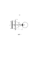
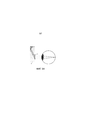
На Фиг. 1 показано стандартное поле зрения (FoV) голографического шлема виртуальной реальности.In FIG. Figure 1 shows the standard field of view (FoV) of a holographic virtual reality helmet.
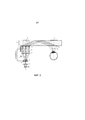
На Фигуре 2 изображена предлагаемая система слежения за поворотом глаза, интегрированная в одну из известных систем виртуальной реальности.The Figure 2 shows the proposed tracking system for turning the eye, integrated into one of the known virtual reality systems.
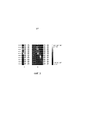
На Фигурах 3A и 3B схематично изображена методика определения поворота глаза фотодиодными массивами размерами 2×2 и 2×10 соответственно.Figures 3A and 3B schematically depict a technique for determining eye rotation with 2 × 2 and 2 × 10 photodiode arrays, respectively.
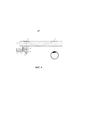
На Фигуре 4 показана предлагаемая система слежения за поворотом глаза.Figure 4 shows the proposed tracking system for turning the eye.
На фигуре 5A показан ход лучей при выполнении второго элемента ввода/вывода 13 в виде отклоняющей дифракционной решетки без оптической силы.Figure 5A shows the path of the rays when performing the second input /
На фигуре 5B показан ход лучей при выполнении второго элемента ввода/вывода 13 в виде голографического оптического элемента, обладающего оптической силой.Figure 5B shows the course of the rays when performing the second input /
На Фигуре 6 показана диаграмма интегрирования предлагаемой системы в известные устройства носимых дисплеев (HMD)The Figure 6 shows a diagram of the integration of the proposed system in the known device wearable displays (HMD)
Подробное описание изобретенияDETAILED DESCRIPTION OF THE INVENTION
Технического задачей, на решение которой направлено предлагаемое изобретение, является создание компактной, невидимой, высокоскоростной системы слежения за поворотом глаза, которую можно использовать как в качестве отдельного устройства, так и встроенной в любой тип устройств, таких как, например, устройства дополненной реальности (AR), виртуальной реальности (VR), смешанной реальности (MR), в устройствах (носимых или нашлемных) дисплеев (HMD).The technical problem to which the invention is directed is to create a compact, invisible, high-speed tracking system for tracking the rotation of the eye, which can be used either as a separate device or built into any type of device, such as, for example, augmented reality devices (AR ), virtual reality (VR), mixed reality (MR), in devices (wearable or helmet-mounted) displays (HMD).
Предлагается компактная, незаметная, высокоскоростная система слежения за поворотом глаза, которая может быть использована, как отдельное устройство (фиг. 4) или интегрирована (фиг. 2) в существующие устройства виртуальной реальности, либо дополненной реальности, либо совмещенной реальности, используемые, например, в шлеме виртуальной реальности. Предлагаемая система позволяет увеличить область, в которой глаз человека видит изображение (Eye Box), то есть, глаз, перемещаясь в пределах этой области при наблюдении дополненной реальности, будет обозревать все поле зрения, что уменьшает дискомфорт при наблюдении дополненной реальности, либо виртуальной реальности, либо совмещенной реальности. Предлагаемая система слежения за поворотом глаза позволяет отслеживать поворот глаза и совмещать его с положением изображения.A compact, inconspicuous, high-speed tracking system for turning the eye is proposed, which can be used as a separate device (Fig. 4) or integrated (Fig. 2) into existing devices of virtual reality, or augmented reality, or combined reality, used, for example, in a virtual reality helmet. The proposed system allows you to increase the area in which the human eye sees the image (Eye Box), that is, the eye, moving within this area when observing augmented reality, will observe the entire field of view, which reduces the discomfort when observing augmented reality, or virtual reality, or combined reality. The proposed tracking system for turning the eye allows you to track the rotation of the eye and combine it with the position of the image.
Система слежения за поворотом глаза содержит инфракрасную подсветку, волновод, дифракционные оптические элементы в виде элементов ввода/вывода и массив фотодиодов. Причем длина волны подсветки выбирается такой, что подсветка является невидимой для глаз. Благодаря использованию в системе в качестве элементов ввода/вывода дифракционных оптических элементов обеспечивается широкий угол обнаружения поворота глаза, осевое освещение и обнаружение, высокая прозрачность, малая толщина и минимальный вес, низкое энергопотребление, точное отслеживание, высокая скорость обработки сигнала, высокая чувствительность, невидимость для пользователя. Предлагаемое изобретение преодолевает все недостатки известного уровня техники. Для обнаружения малых углов поворота глаза используется только один источник света и низкочувствительный детектор с матрицами CCD (ПЗС) и CMOS (КМОП). Для возможности интеграции с устройствами виртуальной реальности информация с дисплея и из системы слежения за поворотом глаза разделяется по состоянию поляризации, по длине волны или с помощью светоделительных покрытий. Для того, чтобы предлагаемая система была достаточно невидимой, для освещения и слежения используется инфракрасное излучение. Для повышения скорости работы системы и понижения энергопотребления используется один источник света и фотодиодный детектор. Для снижения риска повреждения глаза используется только один маломощный инфракрасный источник света, благодаря чему блики от освещения зрачков глаз не мешают распознаванию поворота глаз.The tracking system for turning the eye contains infrared illumination, a waveguide, diffractive optical elements in the form of input / output elements and an array of photodiodes. Moreover, the wavelength of the backlight is chosen such that the backlight is invisible to the eyes. Due to the use of diffractive optical elements as input / output elements in the system, a wide angle of eye rotation detection, axial illumination and detection, high transparency, small thickness and minimal weight, low power consumption, accurate tracking, high signal processing speed, high sensitivity, invisibility are provided for user. The present invention overcomes all the disadvantages of the prior art. To detect small angles of rotation of the eye, only one light source and a low-sensitivity detector with CCD (CCD) and CMOS (CMOS) matrices are used. To be able to integrate with virtual reality devices, information from the display and from the tracking system for turning the eye is divided according to the state of polarization, by wavelength, or using beam splitting coatings. In order for the proposed system to be sufficiently invisible, infrared radiation is used for lighting and tracking. To increase the speed of the system and reduce power consumption, one light source and a photodiode detector are used. To reduce the risk of eye damage, only one low-power infrared light source is used, so that glare from the illumination of the pupils of the eyes does not interfere with the recognition of eye rotation.
Предлагаемая система слежения за поворотом глаза обеспечивает широкое поле зрения, в котором детектируется поворот глаза, и является безопасной для глаз. Кроме того, система, являясь хорошо пропускающей, не затеняет общую картину виртуальной или дополненной реальности. Также, за счет использования волновода и дифракционных элементов в качестве элементов ввода/вывода, система является тонкой и легкой. Предлагаемая система слежения за поворотом глаза позволяет получить очень точное положение глаза, является высокоскоростной, обеспечивает низкое потребление энергии за счет использования массива фотодиодов.The proposed tracking system for turning the eye provides a wide field of view in which the rotation of the eye is detected, and is safe for the eyes. In addition, the system, being well transmissive, does not obscure the overall picture of virtual or augmented reality. Also, through the use of a waveguide and diffraction elements as input / output elements, the system is thin and light. The proposed tracking system for turning the eye allows you to get a very accurate position of the eye, is high-speed, provides low energy consumption through the use of an array of photodiodes.
Общеизвестно, что поле зрения (FoV) голографического шлема виртуальной реальности определяется фокусным расстоянием (f) линзы и размером D промежуточного изображения пространственного модулятора света (где уже сформировано промежуточное изображение) (см. фиг.1).It is well known that the field of view (FoV) of a holographic virtual reality helmet is determined by the focal length (f) of the lens and the size D of the intermediate image of the spatial light modulator (where the intermediate image has already been formed) (see Fig. 1).
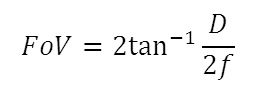
область (h) в пределах которой может располагаться зрачок определяется следующим образом:area (h) within which the pupil can be located is determined as follows:
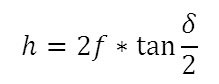
где 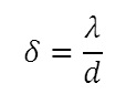
![]()
![]()
![]()
![]()
![]()
![]()
Как видно из фигуры 1 при смещении глаза в сторону от точки, на которой сфокусировано изображение в известных шлемах виртуальной реальности, глаз не будет видеть изображение.As can be seen from figure 1, when the eye is shifted to the side from the point where the image is focused in the known helmets of virtual reality, the eye will not see the image.
На фигуре 2 показана предлагаемая система слежения за поворотом глаза, интегрированная, например, в систему виртуальной реальности (это может быть любая из систем AR, VR, MR, HMD и аналогичные им). Система виртуальной реальности содержит источник изображения, представляющий собой пространственный модулятор света (SLM) 1, первую линзу 2, диафрагму 3, систему поперечного смещения изображения 4, вторую линзу 5 (коллимирующую линзу), инфракрасный делитель 6, первую дифракционную решетку RGB 7, обладающую селективностью по длинам волн. Излучение вводится в волновод 8, распространяется по волноводу путем полного внутреннего отражения, падает на вторую дифракционную решетку RGB 9. Излучение выводится через вторую дифракционную решетку RGB 9 и изображение фокусируется на сетчатке глаза.Figure 2 shows the proposed tracking system for turning the eye, integrated, for example, into a virtual reality system (this can be any of the systems AR, VR, MR, HMD and the like). The virtual reality system contains an image source, which is a spatial light modulator (SLM) 1, the
Предлагаемая система слежения за поворотом глаза содержит источник инфракрасного излучения 10, например, светодиод или лазерный диод, излучающие ближний ИК-диапазон, причем мощность используемого источника выбирается такая, чтобы уровень безопасности излучения соответствовал стандартам безопасности для глаз человека. Необходимо отметить, что стекловидное тело человеческого глаза прозрачно для такого диапазона длин волн. Излучение от упомянутого источника отражается от инфракрасного зеркала 11, проходит через вторую линзу 5, коллимированное излучение проходит через инфракрасный делитель 6. Поскольку излучение находится в ИК диапазоне, то оно проходит через дифракционную решетку RGB 7 без дифракции, попадает на первый элемент ввода/вывода 12, представляющий собой дифракционный оптический элемент ИК-диапазона. Поскольку ИК-излучение, попадая в волновод претерпевает дифракцию на первом элементе ввода/вывода 12, дифрагированное излучение за счет эффекта полного внутреннего отражения распространяется по волноводу 8 и попадает на второй элемент ввода/вывода 13, который представляет собой дифракционный оптический элемент ИК-диапазона и который выводит это излучение в сторону глаза. Если глаз расположен прямо (то есть оптическая ось зрачка перпендикулярна второму элементу ввода/вывода 13), в зрачок попадает излучение (сплошные стрелки показывают ход лучей при одном положении глаза, пунктирные стрелки показывает ход лучей при другом положение глаза, когда глаз переместился), проходящее от второго элемента ввода/вывода 13, перпендикулярно второй дифракционной решетке RGB 9; если оптическая ось зрачка расположена под углом ко второму элементу ввода/вывода 13 в зрачок попадает излучение (пунктирная стрелка), проходящее от второго элемента ввода/вывода 13 под углом ко второй дифракционной решетке RGB 9. Излучение, которое попадает в зрачок, отражается от сетчатки глаза, минуя вторую дифракционную решетку RGB 9 без взаимодействия с ней, попадает на второй элемент ввода/вывода 13, дифрагирует на нем и посредством полного внутреннего отражения проходит волновод, попадает на первый элемент ввода/вывода 12, снова претерпевает дифракцию и выводится из волновода, попадает на инфракрасный делитель 6 и, отражаясь от инфракрасного делителя 6, попадает на массив фотодиодов 14, массив фотодиодов связан с модулем обработки сигнала. Необходимо отметить, что излучение имеет потери в процессе распространения в волноводе и на элементах ввода/вывода, представляющих собой дифракционные элементы (дифракционные элементы характеризуются таким понятием как дифракционная эффективность) и потери при освещении глаза, поскольку пучок, которым освещается глаз, должен быть заведомо больше размера зрачка, и то, что не прошло в зрачок - рассеивается и обратно не возвращается. Инфракрасный делитель может представлять собой селективное зеркало, которое пропускает видимый диапазон, т.е. полностью прозрачно для него, и отражает ИК диапазон. Причем такое селективное зеркало может быть выполнено таким образом, чтобы отражать именно ту длину волны, которая соответствует используемому ИК источнику излучения.The proposed tracking system for turning the eye contains an
Общеизвестно, что дифракционные решетки применяются для ввода излучения в волновод и вывода излучения из волновода. Если в волновод направить недифрагированное излучение, оно пройдет сквозь волновод и не останется в нем, то есть не будет распространяться по волноводу. При использовании дифракционной решетки на входе в волновод излучение, благодаря дифракции, отклоняется на угол полного внутреннего отражения от стенок волновода, что позволяет излучению оставаться в волноводе и распространяться внутри него. При попадании распространяющегося в волноводе излучения на дифракционную решетку, расположенную на выходе из волновода, излучение, претерпевая дифракцию, отклоняется дифракционной решеткой на угол, позволяющий ему выйти из волновода, и не распространяться в волноводе дальше.It is well known that diffraction gratings are used to introduce radiation into a waveguide and to output radiation from a waveguide. If undirected radiation is directed into the waveguide, it will pass through the waveguide and will not remain in it, that is, it will not propagate along the waveguide. When using a diffraction grating at the entrance to the waveguide, the radiation, due to diffraction, deviates by the angle of total internal reflection from the walls of the waveguide, which allows the radiation to remain in the waveguide and propagate inside it. When radiation propagating in a waveguide hits a diffraction grating located at the output of the waveguide, the radiation, undergoing diffraction, is deflected by the diffraction grating by an angle that allows it to exit the waveguide and not propagate further in the waveguide.
На Фигуре 3A схематично изображена методика определения поворота глаза фотодиодным массивом размером 2×2.Figure 3A schematically depicts a technique for determining eye rotation with a 2 × 2 photodiode array.
Если оптическая ось зрачка перпендикулярна ко второму элементу ввода/вывода 13 (то есть глаз смотрит прямо, X00Y00 на фигуре 3), то распределение сигнала по площадкам светодиодов одинаковое. Если оптическая ось зрачка расположена под углом к второму элементу ввода/вывода 13, то есть глаз смотрит в сторону (где X - угловое смещение глаза в стороны, Y - угловое смещение глаза вверх и вниз) -возможны, например, варианты X5°Y0°, X10°Y0°, X15°Y0°, X20°Y0°, X25°Y0°, X30°Y0° на фигуре 3a. Если глаз смотрит вверх или вниз - возможны, например, варианты X0°Y5°, X0°Y10°, X0°Y15°. То есть лучше будет освещена часть фотодетекторов, которая принимает излучение, попавшее в зрачок и отразившееся от сетчатки глаза, освещенная часть массива фотодетекторов показывает поворот глаза. То есть, по освещению фотодетекторов можно легко без всяких алгоритмических расчетов определить поворот глаза, что значительно повышает скорость работы системы.If the optical axis of the pupil is perpendicular to the second input / output element 13 (that is, the eye looks directly, X0 0 Y0 0 in figure 3), then the signal distribution over the LED areas is the same. If the optical axis of the pupil is at an angle to the second input /
Очевидно, что чем большее количество фотодетекторов использовано в массиве, тем больше чувствительность системы, как видно из фигуры 3B, где схематично отображена методика определения поворота глаза фотодиодным массивом 2×10. На фигуре 3а видно, что горизонтальное смещение 20°, 25° и 30° различить нельзя, тогда как с увеличением количества светодиодов (фигура 3b) смещения 20°, 25° и 30° вполне различимы.Obviously, the larger the number of photodetectors used in the array, the greater the sensitivity of the system, as can be seen from Figure 3B, which schematically depicts a technique for determining eye rotation with a 2 × 10 photodiode array. Figure 3a shows that the horizontal displacement of 20 °, 25 ° and 30 ° cannot be distinguished, while with an increase in the number of LEDs (figure 3b), the displacements of 20 °, 25 ° and 30 ° are quite distinguishable.
После определения поворота глаза на систему смещения изображения 4 по обратной связи поступает сигнал от модуля обработки сигналов, приходящих от массива фотодетекторов. Поступивший сигнал дает команду системе смещения изображения 4 на смещение поле зрения виртуального изображения системы виртуальной реальности в ту или иную сторону, чтобы совместить изображение со зрачком глаза. Система смещения изображения может представлять собой любой оптический элемент, способный смещать/сдвигать изображение системы виртуальной реальности. Это может быть, например, зеркало, отклоняющее пучок, или смещающаяся поперек оптической оси призма, или линза, или жидкокристаллический дефлектор и т.п.After determining the rotation of the eye to the
Толщина и вес системы слежения за поворотом глаза минимальны благодаря использованию тонкого волновода с дифракционными решетками или дифракционными оптическими элементами ИК-диапазона в качестве элементов ввода/вывода. С помощью предлагаемой системы возможно захватить всю область, в пределах которой располагается зрачок при движении глаза. Широкий угол поворота глаза определяется количеством элементов массива фотодиодов. Необходимо отметить, что для слежения за конвергенцией, когда меняется дистанция, на которой находится объект наблюдения для каждого глаза используется своя отдельная система слежения за поворотом глаза. Но в устройствах, где информация выводится только для одного глаза можно установить только одну систему слежения за поворотом глаза. При работе устройства виртуальной реальности две системы слежения за поворотом глаза могут согласовываться с помощью компьютерных программ, которые обеспечивают пересчет изображения в случае стереоизображения и смещение изображений для левого и правого глаза, чтобы не было двоения при просмотре двумя глазами, причем для левого и правого глаза изображение должно находится в одном и том же месте пространства. В результате такой компьютерной обработки получается объемное изображение, например, стереоизображение или компьютерно-синтезированная голограмма, благодаря чему можно создать перемещение виртуального объекта в пространстве перед глазами пользователя, или производить слежение на чем сфокусирован взгляд человека.The thickness and weight of the tracking system for turning the eye is minimal due to the use of a thin waveguide with diffraction gratings or diffractive optical elements of the infrared range as input / output elements. Using the proposed system, it is possible to capture the entire area within which the pupil is located when the eye moves. A wide angle of rotation of the eye is determined by the number of elements in the array of photodiodes. It should be noted that for tracking convergence, when the distance at which the object of observation is located for each eye uses its own separate tracking system for turning the eye. But in devices where information is displayed for only one eye, you can install only one tracking system for turning the eye. When operating a virtual reality device, two systems for tracking the rotation of the eye can be coordinated using computer programs that provide image recalculation in the case of a stereo image and image displacement for the left and right eyes so that there is no double vision when viewed with two eyes, and for the left and right eyes the image must be in the same place in space. As a result of such computer processing, a three-dimensional image is obtained, for example, a stereo image or a computer-synthesized hologram, due to which it is possible to create a movement of a virtual object in space in front of the user's eyes, or to monitor what the human eye is focused on.
Поскольку зрение каждого человека индивидуально, а именно индивидуально межглазное расстояние, глубина посадки глаз, наличие косоглазия и т. п., требуется калибровка перед началом использования как одной системы слежения за поворотом глаза, так и двух согласованных систем слежения за поворотом глаза.Since the vision of each person is individual, namely, the individual interocular distance, the depth of eye fit, the presence of strabismus, etc., calibration is required before using both one tracking system for turning the eye and two coordinated tracking systems for turning the eye.
На Фигуре 4 показана предлагаемая система слежения за глазом с дифракционными элементами в качестве элементов ввода/вывода для ввода/вывода излучений из волновода, работающая в автономном режиме. Первый элемент ввода/вывода 12 может быть представлена дифракционной решеткой без изменяющегося периода, то есть угол дифракции для всех лучей будет одинаков, за счет чего, все лучи будут распространяться в волноводе параллельно. Излучение, отраженное от сетчатки, возвращается по тому же направлению, по которому пришло в зрачок, то есть излучение попадет в ту же самую точку на втором элементе ввода/вывода 13, испытает ту же дифракцию и вернется под тем же самым углом, под которым оно падало на первый элемент ввода/вывода 12, то есть легко определить с какой стороны пришло отраженное излучение, а с какой стороны не пришло излучение. При таком подходе достигается большой угол детектирования поворота глаза, высокая прозрачность системы, поскольку элементы ввода/вывода не взаимодействуют с излучением, видимым для человеческого глаза, и волновод является прозрачным. Предлагаемая система обладает низкой толщиной, за счет использования волновода с минимальным весом. Система обладает высокой точностью определения поворота глаза, поскольку используется эффект световозвращения, и детектируется именно то излучение, которое прошло зрачок и отразилось от сетчатки. Система также обладает высокой скоростью обработки сигнала и получения информации о повороте глаза в реальном времени, поскольку имеется прямая корреляция между отклонением зрачка и сигналом, получаемым массивом фотодиодов 14. То есть как только изменился сигнал на массиве фотодиодов 14, модуль обработки сигналов 15 констатирует изменение поворота глаза. Система имеет высокую чувствительность, поскольку размер площадки массива фотодиодов 14 может быть любым. Также, за счет использования невидимого глазу ИК-излучения маленькой мощности - система безопасна для глаз. Система потребляет мало энергии, за счет использования маломощного источника ИК-излучения и массива фотодиодов.Figure 4 shows the proposed eye tracking system with diffraction elements as input / output elements for input / output of radiation from the waveguide, operating in stand-alone mode. The first input /
Второй элемент ввода/вывода 13 может представлять собой линзу или плоскую дифракционную решетку (см. фигуру 5A), то есть отклоняющую дифракционную решетку без оптической силы, или объемную дифракционную решетку, или дифракционный элемент, обладающий оптической силой, например, в виде голографического оптического элемента, обладающего оптической силой (см. фигуру 5B). Общеизвестно, что плоской называется дифракционная решетка, где набег фазы, и соответственно отклонение лучей, происходит за счет рельефа, изменения толщины материала; а объемной называется дифракционная решетка, на которой дифракция происходит внутри материала за счет изменения показателя преломления.The second input /
Как показано на фигуре 5A, излучение, пройдя дифракционный оптический элемент с регулярной структурой, фокусируется хрусталиком на сетчатке глаза. На фигуре 5B показано прохождение излучения через дифракционный оптический элемент с нерегулярной структурой, в результате чего параллельный пучок, после прохождения такого элемента выходит сформированный таким образом, чтобы сфокусироваться в центре вращения глаза, что позволяет всегда иметь излучение, распространяющееся перпендикулярно к зрачку, в каком бы положении глаз не находился. Излучение, нормальное к зрачку повышает эффективность и снижает энергозатраты системы, то есть нет необходимости освещать глаз широким пучком излучения, это позволяет получить еще более широкую область слежения за глазом, поскольку при повороте глаза всегда найдутся лучи, идущие по нормали к зрачку.As shown in FIG. 5A, radiation, having passed a diffractive optical element with a regular structure, is focused by the lens on the retina of the eye. Figure 5B shows the passage of radiation through a diffractive optical element with an irregular structure, as a result of which a parallel beam, after passing through such an element, is formed so as to focus in the center of rotation of the eye, which allows you to always have radiation propagating perpendicular to the pupil, in which eye position was not. Radiation normal to the pupil increases the efficiency and reduces the energy consumption of the system, that is, there is no need to illuminate the eye with a wide beam of radiation, this allows you to get an even wider tracking area for the eye, because when you turn the eye, there will always be rays going along the normal to the pupil.
Необходимо заметить, что излучение может проходить и через склеру глаза, но в склере глаза преобладает рассеивание и поглощение излучения, и поэтому оно не может отразиться от сетчатки глаза. Излучение, которое попадает в зрачок не по нормали, а под углом к зрачку, попадает на сетчатку глаза, точно также отражается, как и упавшее по нормали, снова проходит через хрусталик выходят и распространяются в обратном направлении под таким же по величине углом. Однако, излучение, которое попадает в зрачок не по нормали является неинформативным, поскольку после отражения от сетчатки может не попасть в волновод, или не введется в волновод под нужным углом, или может остаться в волноводе, поскольку не выведется из волновода, или выведется из волновода, но в направлении мимо модуля фотодиодов. То есть необходимо, чтобы излучение попадало в зрачок именно по нормали, тогда оно точно вернется в ту же самую точку на инфракрасном делителе, от которой попало в волновод, и, часть, отразившаяся от делителя, точно попадет на массив фотодиодов.It should be noted that radiation can also pass through the sclera of the eye, but scattering and absorption of radiation predominate in the sclera of the eye, and therefore it cannot be reflected from the retina of the eye. Radiation that enters the pupil not along the normal, but at an angle to the pupil, hits the retina of the eye, just as reflected as it fell along the normal, again passes through the lens and comes out and propagates in the opposite direction at the same angle. However, radiation that enters the pupil in a non-normal fashion is uninformative, because after reflection from the retina it may not enter the waveguide, or may not enter the waveguide at the desired angle, or may remain in the waveguide because it will not be pulled out of the waveguide, or will be removed from the waveguide but in the direction past the photodiode module. That is, it is necessary that the radiation hit the pupil exactly in the normal direction, then it will definitely return to the same point on the infrared divider, from which it fell into the waveguide, and, the part reflected from the divider will definitely hit the array of photodiodes.
Предлагаемая система легко может быть интегрирована в обычные устройства носимого (нашлемного, наголовного) дисплея (HMD). Как показано на фигуре 6 предлагаемая система слежения за поворотом глаза содержит источник излучения, представляющий собой источник инфракрасного излучения 10; модуль перенаправления и распространения света, представляющий собой волновод 8, который также используется устройством HMD, с первым элементом ввода/вывода 12 и вторым элементом ввода/вывода 13; массив фотодиодов 14; модуль обработки сигнала 15. Модуль обработки сигнала, получивший и обработавший информацию о повороте глаза выдает сигнал системе обратной связи, состоящей из своего модуля обработки сигналов и системы смещения изображения 4, сигнал указывает как необходимо сместиться системе смещения 4, чтобы изображение виртуальной реальности подстроилось под поворот глаза. Этот же сигнал приходит к системе виртуальной реальности, которая в свою очередь также содержит свой модуль обработки сигналов и корректирует изображение в модуле изображения HMD, в зависимости от поворота глаза. Необходимо отметить, что предлагаемая система слежения за поворотом глаза, интегрированная в известные устройства дополненной или виртуальной реальности, вообще не увеличивает размеры известных устройств дополненной или виртуальной реальности.The proposed system can easily be integrated into conventional devices portable (helmet, head-mounted) display (HMD). As shown in figure 6, the proposed tracking system for turning the eye contains a radiation source, which is a source of
В предлагаемой системе возможно предусмотреть появление дисторсий, которые могут вносить расфокусировку изображения на массиве фотодетекторов. В случае, когда в качестве второго элемента ввода/вывода 13 используется дифракционный элемент с оптической силой, для повышения чувствительности системы, важно совмещать точку фокусировки лучей, прошедших зрачок с центром вращения сферы глаза, то есть глаз должен быть расположен в расчетной позиции. Однако, если пользователь, например, приблизит глаз ближе, чем это необходимо для нормальной работы системы, то возникает дисторсия, то есть точка фокусировки лучей, прошедших зрачок будет расположена не в центре сферы глаза, и соответственно отраженные от сетчатки лучи будут распространяться не параллельно, из-за чего на фотодиоде получится расфокусированная картина освещения, то есть уровень сигнала упадет. Для избежания подобной ситуации между инфракрасным делителем 6 и волноводом 8 можно поставить линзу с переменным фокусом, причем, когда глаз расположен в расчетной позиции, линза с переменным фокусом выключена (то есть ее оптическая сила равна нулю), когда глаз выходит из расчетной позиции, линза с переменным фокусом работает таким образом, что излучение фокусируется в центре сферы глаза. То есть показатель преломления такой линзы меняется в зависимости от приложенного напряжения. Подобная линза может быть выполнена, например, из жидкокристаллического материала.In the proposed system, it is possible to provide for the appearance of distortions, which can introduce defocusing of the image on the array of photodetectors. In the case when a diffraction element with optical power is used as the second input /
Инфракрасный делитель 6 может быть простым частично отражающим делителем, например, 50% ИК-излучения проходит через делитель и 50% ИК-излучения отражается делителем, или интерференционным зеркалом, селективным к выбранной длине волны или другим подходящим элементом.The
Также инфракрасный делитель 6 может содержать поляризационное покрытие, то есть, если поляризация падающего излучения и покрытия совпадают, то делитель пропускает излучение. После такого делителя устанавливается пластинка λ/4, которая поворачивает поляризацию на ортогональную. Поскольку поляризационное покрытие может, например, пропускать p-поляризацию и отражать s-поляризацию (или наоборот) то пропущенное излучение, например, с p-поляризацией, проходит четвертьволновую пластину, получая круговую поляризацию, вернувшись после отражения от сетчатки глаза, опять проходит четвертьволновую пластину и получает s-поляризацию, которая полностью отражается поляризационным покрытием светоделителя и попадает на массив фотодиодов без потери интенсивности.Also, the
Волновод 8 может иметь различные формы, например, волновод может быть прямым или волновод может иметь искривленные поверхности, в этом случае первый элемент ввода/вывода 12 и второй элемент ввода/вывода 13 могут быть скорректированы под кривизну волновода при изготовлении.The
При осуществлении предлагаемой системы нет необходимости использовать в качестве массива фотодиодов 14 матрицу с высоким разрешением, но важно использовать матрицу, имеющую высокую скорость обработки сигнала, то есть анализ изображения с матрицы и цифровая обработка изображения не требуются, а по разности сигналов с соседних элементов возможно снимать аналоговый управляющий сигнал. Если картина на матрице симметричная, значит никакой сигнал на систему смещения изображения не подается, если картина на матрице несимметричная, значит на систему смещения изображения подается разностный сигнал, и изображение смещается. Такие матрицы должны иметь частоту обновления порядка 1,6-2 кГц, что намного быстрее, чем микросаккады глаз, то есть такие матрицы могут фиксировать даже микросаккады глаз.When implementing the proposed system, it is not necessary to use a matrix with a high resolution as an array of
Предлагаемая система слежения за поворотом глаза может быть использована в различных областях деятельности человека.The proposed tracking system for turning the eye can be used in various fields of human activity.
Например, предлагаемую систему, интегрированную в очки совмещенной реальности, могут использовать туристы. При знакомстве с достопримечательностями туристу, имеющему очки совмещенной реальности со встроенной системой слежения за поворотом глаза, достаточно, например, просто остановить взгляд на достопримечательности, заинтересовавшей его, и тут же перед глазами туриста возникнет информация, описывающая эту достопримечательность.For example, the proposed system, integrated into the combined reality glasses, can be used by tourists. When you get acquainted with the sights, a tourist who has glasses of combined reality with an integrated tracking system for turning his eyes, it is enough, for example, just to stop looking at the sights that interest him, and immediately before the eyes of the tourist there will be information describing this attraction.
Предлагаемую систему можно использовать для задания PIN-кода. Пользователь надевает очки со встроенной системой слежения за поворотом глаза и взглядом «набирает» PIN-код, останавливаясь на нужных цифрах.The proposed system can be used to set a PIN code. The user puts on glasses with a built-in tracking system for turning the eye and looking “dials” the PIN code, stopping at the desired numbers.
Предлагаемая система может быть использована для улучшения качества жизни инвалидов и обездвиженных больных.The proposed system can be used to improve the quality of life of people with disabilities and immobilized patients.
Система слежения за поворотом глаза может быть использована для мониторинга усталости человека. Например, для контроля за водителями, система может определять, что человека клонит ко сну по микросаккадам глаз.The eye tracking system can be used to monitor human fatigue. For example, to control drivers, the system can determine that a person is falling asleep by microsaccades of the eyes.
Система слежения за поворотом глаза может быть использована при сборе информации о товарах, интересующих покупателя. То есть возможно фиксировать остановку взгляда покупателя на тех или иных товарах, то есть определять степень интереса покупателя к тем или иным товарам.The eye tracking system can be used to collect information about products of interest to the buyer. That is, it is possible to fix the stopping of the gaze of the buyer on certain goods, that is, to determine the degree of buyer interest in certain goods.
Хотя изобретение описано в связи с некоторыми иллюстративными вариантами осуществления, следует понимать, что сущность изобретения, не ограничивается этими конкретными вариантами осуществления. Напротив, предполагается, что сущность изобретения включает в себя все альтернативы, коррекции и эквиваленты, которые могут быть включены в сущность и объем формулы изобретения.Although the invention has been described in connection with some illustrative embodiments, it should be understood that the invention is not limited to these specific embodiments. On the contrary, it is assumed that the invention includes all alternatives, corrections and equivalents that may be included in the essence and scope of the claims.
Кроме того, изобретение сохраняет все эквиваленты заявляемого изобретения, даже если пункты формулы изобретения изменяются в процессе рассмотрения.In addition, the invention retains all equivalents of the claimed invention, even if the claims change during the review process.
Claims (52)
Priority Applications (4)
| Application Number | Priority Date | Filing Date | Title |
|---|---|---|---|
| RU2019103205A RU2700373C1 (en) | 2019-02-05 | 2019-02-05 | Eye tracking system |
| KR1020190113016A KR20200096716A (en) | 2019-02-05 | 2019-09-11 | Eye tracking device and display apparatus including the same |
| US16/752,114 US11861063B2 (en) | 2019-02-05 | 2020-01-24 | Eye-tracking device and display apparatus including the same |
| EP20154332.9A EP3722863A1 (en) | 2019-02-05 | 2020-01-29 | Eye-tracking device and display apparatus including the same |
Applications Claiming Priority (1)
| Application Number | Priority Date | Filing Date | Title |
|---|---|---|---|
| RU2019103205A RU2700373C1 (en) | 2019-02-05 | 2019-02-05 | Eye tracking system |
Publications (1)
| Publication Number | Publication Date |
|---|---|
| RU2700373C1 true RU2700373C1 (en) | 2019-09-16 |
Family
ID=67989939
Family Applications (1)
| Application Number | Title | Priority Date | Filing Date |
|---|---|---|---|
| RU2019103205A RU2700373C1 (en) | 2019-02-05 | 2019-02-05 | Eye tracking system |
Country Status (3)
| Country | Link |
|---|---|
| EP (1) | EP3722863A1 (en) |
| KR (1) | KR20200096716A (en) |
| RU (1) | RU2700373C1 (en) |
Cited By (1)
| Publication number | Priority date | Publication date | Assignee | Title |
|---|---|---|---|---|
| WO2021062941A1 (en) * | 2019-09-30 | 2021-04-08 | 中山大学 | Grating-based optical waveguide light field display system |
Citations (4)
| Publication number | Priority date | Publication date | Assignee | Title |
|---|---|---|---|---|
| RU106837U1 (en) * | 2009-06-05 | 2011-07-27 | Александр Викторович Тихов | OPHTHAL SURGICAL REFRACTION LASER SYSTEM |
| US20170277259A1 (en) * | 2016-03-24 | 2017-09-28 | Daqri, Llc | Eye tracking via transparent near eye lens |
| US9804389B2 (en) * | 2012-05-11 | 2017-10-31 | Digilens, Inc. | Apparatus for eye tracking |
| WO2018122859A1 (en) * | 2016-12-31 | 2018-07-05 | Lumus Ltd. | Eye tracker based on retinal imaging via light-guide optical element |
Family Cites Families (2)
| Publication number | Priority date | Publication date | Assignee | Title |
|---|---|---|---|---|
| US10684477B2 (en) * | 2014-09-30 | 2020-06-16 | Omnivision Technologies, Inc. | Near-eye display device and methods with coaxial eye imaging |
| US10674143B2 (en) * | 2017-05-12 | 2020-06-02 | Qualcomm Incorporated | System for eye tracking |
-
2019
- 2019-02-05 RU RU2019103205A patent/RU2700373C1/en active
- 2019-09-11 KR KR1020190113016A patent/KR20200096716A/en unknown
-
2020
- 2020-01-29 EP EP20154332.9A patent/EP3722863A1/en active Pending
Patent Citations (5)
| Publication number | Priority date | Publication date | Assignee | Title |
|---|---|---|---|---|
| RU106837U1 (en) * | 2009-06-05 | 2011-07-27 | Александр Викторович Тихов | OPHTHAL SURGICAL REFRACTION LASER SYSTEM |
| US9804389B2 (en) * | 2012-05-11 | 2017-10-31 | Digilens, Inc. | Apparatus for eye tracking |
| US20180113303A1 (en) * | 2012-05-11 | 2018-04-26 | Digilens, Inc. | Apparatus for eye tracking |
| US20170277259A1 (en) * | 2016-03-24 | 2017-09-28 | Daqri, Llc | Eye tracking via transparent near eye lens |
| WO2018122859A1 (en) * | 2016-12-31 | 2018-07-05 | Lumus Ltd. | Eye tracker based on retinal imaging via light-guide optical element |
Cited By (1)
| Publication number | Priority date | Publication date | Assignee | Title |
|---|---|---|---|---|
| WO2021062941A1 (en) * | 2019-09-30 | 2021-04-08 | 中山大学 | Grating-based optical waveguide light field display system |
Also Published As
| Publication number | Publication date |
|---|---|
| KR20200096716A (en) | 2020-08-13 |
| EP3722863A1 (en) | 2020-10-14 |
Similar Documents
| Publication | Publication Date | Title |
|---|---|---|
| JP7485720B2 (en) | Eye imaging device using diffractive optical elements - Patents.com | |
| EP3685215B1 (en) | Augmented reality display with waveguide configured to capture images of eye and/or environment | |
| US20220244546A1 (en) | Head-mounted display eyeball tracker integrated system | |
| US20230341695A1 (en) | Diffractive optical elements with optical power | |
| US20230077228A1 (en) | Holographic in-field illuminator | |
| US8582206B2 (en) | Laser-scanning virtual image display | |
| CN112558751B (en) | Sight tracking method of intelligent glasses based on MEMS and optical waveguide lens | |
| CN115145023A (en) | Device for deriving a gaze direction of a human eye | |
| US11846778B2 (en) | System for providing illumination of the eye | |
| US11256213B2 (en) | Holographic pattern generation for head-mounted display (HMD) eye tracking using an array of parabolic mirrors | |
| US10948873B2 (en) | Holographic pattern generation for head-mounted display (HMD) eye tracking using a lens array | |
| US10838362B2 (en) | Holographic pattern generation for head-mounted display (HMD) eye tracking using a prism array | |
| CN111856749A (en) | Display device and method | |
| US20200192280A1 (en) | Holographic Pattern Generation for Head-Mounted Display (HMD) Eye Tracking Using a Diffractive Optical Element | |
| KR20220046494A (en) | Eye tracking method and eye tracking sensor | |
| RU2700373C1 (en) | Eye tracking system | |
| WO2022196650A1 (en) | Line-of-sight tracking system and virtual image display device | |
| US11281160B2 (en) | Holographic pattern generation for head-mounted display (HMD) eye tracking using a fiber exposure | |
| US10942489B2 (en) | Wide-field holographic pattern generation for head-mounted display (HMD) eye tracking | |
| WO2022130372A1 (en) | Optical systems and methods for eye tracking based on eye imaging via collimating element and light-guide optical element |