RU2684560C2 - Physiological property determination device - Google Patents
Physiological property determination device Download PDFInfo
- Publication number
- RU2684560C2 RU2684560C2 RU2016139135A RU2016139135A RU2684560C2 RU 2684560 C2 RU2684560 C2 RU 2684560C2 RU 2016139135 A RU2016139135 A RU 2016139135A RU 2016139135 A RU2016139135 A RU 2016139135A RU 2684560 C2 RU2684560 C2 RU 2684560C2
- Authority
- RU
- Russia
- Prior art keywords
- determining
- light
- physiological
- physiological indicator
- detecting
- Prior art date
Links
- 230000001766 physiological effect Effects 0.000 title abstract 5
- 238000001514 detection method Methods 0.000 claims abstract description 67
- 238000000034 method Methods 0.000 claims abstract description 16
- 238000004590 computer program Methods 0.000 claims abstract description 11
- 230000010412 perfusion Effects 0.000 claims abstract description 9
- 210000000707 wrist Anatomy 0.000 claims description 21
- 125000006850 spacer group Chemical group 0.000 claims description 10
- 230000036962 time dependent Effects 0.000 claims description 7
- 230000001419 dependent effect Effects 0.000 claims description 6
- 230000000977 initiatory effect Effects 0.000 claims description 2
- 230000000694 effects Effects 0.000 abstract description 2
- 239000003814 drug Substances 0.000 abstract 1
- 239000000126 substance Substances 0.000 abstract 1
- 239000003086 colorant Substances 0.000 description 14
- 239000008280 blood Substances 0.000 description 10
- 210000004369 blood Anatomy 0.000 description 10
- 238000005516 engineering process Methods 0.000 description 8
- 238000005259 measurement Methods 0.000 description 4
- 239000004744 fabric Substances 0.000 description 3
- QVGXLLKOCUKJST-UHFFFAOYSA-N atomic oxygen Chemical compound [O] QVGXLLKOCUKJST-UHFFFAOYSA-N 0.000 description 2
- 230000008901 benefit Effects 0.000 description 2
- 210000004204 blood vessel Anatomy 0.000 description 2
- 230000008859 change Effects 0.000 description 2
- 239000003795 chemical substances by application Substances 0.000 description 2
- 230000001427 coherent effect Effects 0.000 description 2
- 238000005265 energy consumption Methods 0.000 description 2
- 229910052760 oxygen Inorganic materials 0.000 description 2
- 239000001301 oxygen Substances 0.000 description 2
- 230000036772 blood pressure Effects 0.000 description 1
- 238000004891 communication Methods 0.000 description 1
- 230000000295 complement effect Effects 0.000 description 1
- 230000007613 environmental effect Effects 0.000 description 1
- 238000001914 filtration Methods 0.000 description 1
- 239000011521 glass Substances 0.000 description 1
- 238000005286 illumination Methods 0.000 description 1
- 230000006872 improvement Effects 0.000 description 1
- 230000003993 interaction Effects 0.000 description 1
- 230000001678 irradiating effect Effects 0.000 description 1
- 239000000463 material Substances 0.000 description 1
- 230000003287 optical effect Effects 0.000 description 1
- 238000005457 optimization Methods 0.000 description 1
- 230000035515 penetration Effects 0.000 description 1
- 230000008569 process Effects 0.000 description 1
- 230000010349 pulsation Effects 0.000 description 1
- 230000009467 reduction Effects 0.000 description 1
- 239000004065 semiconductor Substances 0.000 description 1
Images
Classifications
-
- A—HUMAN NECESSITIES
- A61—MEDICAL OR VETERINARY SCIENCE; HYGIENE
- A61B—DIAGNOSIS; SURGERY; IDENTIFICATION
- A61B5/00—Measuring for diagnostic purposes; Identification of persons
- A61B5/02—Detecting, measuring or recording pulse, heart rate, blood pressure or blood flow; Combined pulse/heart-rate/blood pressure determination; Evaluating a cardiovascular condition not otherwise provided for, e.g. using combinations of techniques provided for in this group with electrocardiography or electroauscultation; Heart catheters for measuring blood pressure
- A61B5/024—Detecting, measuring or recording pulse rate or heart rate
- A61B5/02416—Detecting, measuring or recording pulse rate or heart rate using photoplethysmograph signals, e.g. generated by infrared radiation
- A61B5/02427—Details of sensor
-
- A—HUMAN NECESSITIES
- A61—MEDICAL OR VETERINARY SCIENCE; HYGIENE
- A61B—DIAGNOSIS; SURGERY; IDENTIFICATION
- A61B5/00—Measuring for diagnostic purposes; Identification of persons
- A61B5/02—Detecting, measuring or recording pulse, heart rate, blood pressure or blood flow; Combined pulse/heart-rate/blood pressure determination; Evaluating a cardiovascular condition not otherwise provided for, e.g. using combinations of techniques provided for in this group with electrocardiography or electroauscultation; Heart catheters for measuring blood pressure
- A61B5/024—Detecting, measuring or recording pulse rate or heart rate
- A61B5/02416—Detecting, measuring or recording pulse rate or heart rate using photoplethysmograph signals, e.g. generated by infrared radiation
-
- A—HUMAN NECESSITIES
- A61—MEDICAL OR VETERINARY SCIENCE; HYGIENE
- A61B—DIAGNOSIS; SURGERY; IDENTIFICATION
- A61B5/00—Measuring for diagnostic purposes; Identification of persons
- A61B5/02—Detecting, measuring or recording pulse, heart rate, blood pressure or blood flow; Combined pulse/heart-rate/blood pressure determination; Evaluating a cardiovascular condition not otherwise provided for, e.g. using combinations of techniques provided for in this group with electrocardiography or electroauscultation; Heart catheters for measuring blood pressure
- A61B5/024—Detecting, measuring or recording pulse rate or heart rate
- A61B5/02438—Detecting, measuring or recording pulse rate or heart rate with portable devices, e.g. worn by the patient
-
- A—HUMAN NECESSITIES
- A61—MEDICAL OR VETERINARY SCIENCE; HYGIENE
- A61B—DIAGNOSIS; SURGERY; IDENTIFICATION
- A61B5/00—Measuring for diagnostic purposes; Identification of persons
- A61B5/68—Arrangements of detecting, measuring or recording means, e.g. sensors, in relation to patient
- A61B5/6801—Arrangements of detecting, measuring or recording means, e.g. sensors, in relation to patient specially adapted to be attached to or worn on the body surface
- A61B5/6802—Sensor mounted on worn items
- A61B5/681—Wristwatch-type devices
-
- A—HUMAN NECESSITIES
- A61—MEDICAL OR VETERINARY SCIENCE; HYGIENE
- A61B—DIAGNOSIS; SURGERY; IDENTIFICATION
- A61B5/00—Measuring for diagnostic purposes; Identification of persons
- A61B5/72—Signal processing specially adapted for physiological signals or for diagnostic purposes
- A61B5/7203—Signal processing specially adapted for physiological signals or for diagnostic purposes for noise prevention, reduction or removal
- A61B5/7207—Signal processing specially adapted for physiological signals or for diagnostic purposes for noise prevention, reduction or removal of noise induced by motion artifacts
- A61B5/721—Signal processing specially adapted for physiological signals or for diagnostic purposes for noise prevention, reduction or removal of noise induced by motion artifacts using a separate sensor to detect motion or using motion information derived from signals other than the physiological signal to be measured
Landscapes
- Health & Medical Sciences (AREA)
- Life Sciences & Earth Sciences (AREA)
- Engineering & Computer Science (AREA)
- Cardiology (AREA)
- Surgery (AREA)
- Animal Behavior & Ethology (AREA)
- Pathology (AREA)
- Physics & Mathematics (AREA)
- Biomedical Technology (AREA)
- Heart & Thoracic Surgery (AREA)
- Medical Informatics (AREA)
- Molecular Biology (AREA)
- Veterinary Medicine (AREA)
- Biophysics (AREA)
- General Health & Medical Sciences (AREA)
- Public Health (AREA)
- Physiology (AREA)
- Signal Processing (AREA)
- Artificial Intelligence (AREA)
- Computer Vision & Pattern Recognition (AREA)
- Psychiatry (AREA)
- Measuring Pulse, Heart Rate, Blood Pressure Or Blood Flow (AREA)
- Measurement Of The Respiration, Hearing Ability, Form, And Blood Characteristics Of Living Organisms (AREA)
- Investigating Or Analysing Materials By Optical Means (AREA)
Abstract
Description
ОБЛАСТЬ ТЕХНИКИFIELD OF TECHNOLOGY
Настоящее изобретение относится к устройству, способу и компьютерной программе для определения физиологического показателя, для определения физиологического показателя субъекта.The present invention relates to a device, method and computer program for determining a physiological index, for determining the physiological index of a subject.
УРОВЕНЬ ТЕХНИКИBACKGROUND
US 2010/0268094 A1 раскрывает устройство для определения частоты пульса субъекта. Устройство содержит источник света для испускания света в часть тела и цифровую камеру, предназначенную для размещения около части тела или в контакте с ней, для обнаружения света после прохождения через часть тела, причем частота пульса определяется на основе изменений обнаруженного света. Однако, в зависимости от источника света, используемого для освещения части тела, камеры и особенностей тела, через которое проходит свет, точность определяемой частоты пульса может снижаться.US 2010/0268094 A1 discloses a device for determining the heart rate of a subject. The device comprises a light source for emitting light into a body part and a digital camera designed to be placed near the body part or in contact with it, for detecting light after passing through the body part, the pulse rate being determined based on changes in the detected light. However, depending on the light source used to illuminate the part of the body, the camera, and the characteristics of the body through which the light passes, the accuracy of the detected heart rate may decrease.
US 2012/195486 A1 раскрывает дистанционную фотоплетизмографическую систему для дистанционного определения частоты сердечных сокращений живого существа. Система содержит несколько источников света для облучения живого существа и видеокамеру для дистанционного обнаружения видеоизображения живого существа. Система выполнена с возможностью определения частоты сердечных сокращений на основе дистанционно захватываемого видеоизображения.US 2012/195486 A1 discloses a remote photoplethysmographic system for remotely determining a living creature's heart rate. The system contains several light sources for irradiating a living creature and a video camera for remote detection of video images of a living creature. The system is configured to determine a heart rate based on a remotely captured video image.
РАСКРЫТИЕ СУЩНОСТИ ИЗОБРЕТЕНИЯSUMMARY OF THE INVENTION
Целью настоящего изобретения является создание устройства, способа и компьютерной программы для определения физиологического показателя, которые обеспечивают возможность улучшенного определения физиологического показателя субъекта.The aim of the present invention is to provide a device, method and computer program for determining a physiological index, which provide the possibility of improved determination of the physiological index of the subject.
Согласно первому аспекту настоящего изобретения предложено устройство для определения физиологического показателя для определения физиологического показателя субъекта, содержащее:According to a first aspect of the present invention, there is provided a device for determining a physiological index for determining a physiological index of a subject, comprising:
- по меньшей мере два источника света для испускания по меньшей мере двух лучей света с различными длинами волн в ткань субъекта,at least two light sources for emitting at least two rays of light with different wavelengths into the tissue of the subject,
- датчик света, имеющий двухмерную детектирующую поверхность, для обнаружения света, прошедшего через ткань, в зависимости от длины волны и для генерирования двухмерного изображения, зависящего от длины волны, на основе обнаруженного света,- a light sensor having a two-dimensional detecting surface, for detecting light transmitted through the tissue, depending on the wavelength and to generate a two-dimensional image, depending on the wavelength, based on the detected light,
- контроллер для раздельного управления интенсивностями лучей света разных источников света таким образом, чтобы не допускать перегрузки датчика света, и- a controller for separately controlling the intensities of the light rays of different light sources in such a way as to prevent overloading the light sensor, and
- модуль определения физиологического показателя для определения физиологического показателя на основе сгенерированного двухмерного изображения, зависящего от длины волны.- a module for determining a physiological indicator for determining a physiological indicator based on the generated two-dimensional image, depending on the wavelength.
Поскольку контроллер выполнен с возможностью раздельного управления интенсивностями лучей света разных источников света, освещение ткани субъекта для каждой длины волны может быть независимо оптимизировано, например, таким образом, что отношение сигнал/шум оптимизируется для каждой соответствующей длины волны. Это может обеспечить улучшенное определение физиологического показателя на основе двухмерного изображения, зависящего от длины волны. Модуль определения физиологического показателя, например, выполнен с возможностью определения частоты пульса в качестве физиологического показателя. Благодаря выполнению контроллера с возможностью раздельного управления интенсивностями лучей света таким образом, что датчик света не перегружается, обеспечивается дополнительное улучшение качества определения физиологического показателя.Since the controller is capable of separately controlling the intensities of light rays of different light sources, the illumination of the subject tissue for each wavelength can be independently optimized, for example, so that the signal-to-noise ratio is optimized for each corresponding wavelength. This can provide an improved definition of a physiological index based on a two-dimensional image depending on the wavelength. The module for determining a physiological indicator, for example, is configured to determine the pulse rate as a physiological indicator. Due to the implementation of the controller with the ability to separately control the intensities of the light rays in such a way that the light sensor is not overloaded, an additional improvement in the quality of determining the physiological indicator is provided.
В одном варианте реализации, указанные по меньшей мере два источника света представляют собой три источника света, испускающие три разных луча света с различными длинами волн. Источники света, например, выполнены с возможностью испускания лучей синего, зеленого и красного света. Предпочтительно, источники света включают в себя лазер и/или светоизлучающий диод (СИД). Двухмерная детектирующая поверхность, предпочтительно, содержит двухмерную схему размещения детектерных элементов, при этом каждый детектерный элемент генерирует детектирующие сигналы, зависящие от длины волны, для генерирования двухмерного изображения, зависящего от длины волны. Двухмерное изображение, зависящее от длины волны, является, например, зависимым от времени и содержит несколько кадров двухмерного изображения для разных моментов времени.In one embodiment, said at least two light sources are three light sources emitting three different light beams with different wavelengths. Light sources, for example, are configured to emit rays of blue, green and red light. Preferably, the light sources include a laser and / or a light emitting diode (LED). The two-dimensional detecting surface preferably contains a two-dimensional arrangement of detector elements, wherein each detector element generates detection signals depending on the wavelength to generate a two-dimensional image depending on the wavelength. A two-dimensional image, depending on the wavelength, is, for example, time-dependent and contains several frames of a two-dimensional image for different points in time.
В одном варианте реализации, устройство дополнительно содержит проницаемую для лучей света проставку, причем проставка размещена перед детектирующей поверхностью. Проставка используется, например, если источники света представляют собой лазеры, испускающие когерентный свет, при этом в данном случае при использовании проставки, датчиком света генерируется спекл-изображение, которое может использоваться модулем определения физиологического показателя для определения физиологического показателя.In one embodiment, the device further comprises a spacer permeable to light rays, the spacer being placed in front of the detecting surface. A spacer is used, for example, if the light sources are lasers emitting coherent light, and in this case, when using the spacer, a speckle image is generated by the light sensor, which can be used by the physiological index determination module to determine the physiological index.
В другом варианте реализации, контроллер может быть выполнен с возможностью управления источниками света таким образом, что детектирующая поверхность принимает не максимальное количество света, что могло быть возможно без перегрузки датчика света, а меньшее количество света. Разница между максимальным количеством и меньшим количеством может быть заранее определена или определяться контроллером для разных длин волн. Это может соответствовать ожидаемой флуктуации интенсивности света вследствие движения устройства для определения физиологического показателя. Например, контроллер может быть выполнен с возможностью отличия флуктуаций интенсивности света, обусловленных физиологическим показателем, подлежащим измерению, от других типов флуктуаций интенсивности света, которые могут быть обусловлены движением, и управления источниками света таким образом, что датчик света не перегружен, даже если присутствуют другие типы флуктуаций света. Если известно, что физиологический показатель обуславливает флуктуации интенсивности света в некотором диапазоне частот, то могут наблюдаться флуктуации интенсивности света за пределами этого диапазона частот и может определяться соответствующая максимальная амплитуда флуктуации интенсивности. Разница между максимальным количеством света и меньшим количеством света может соответствовать этой максимальной амплитуде. После того, как разница была определена, она может сохраняться в контроллере и использоваться для последующих измерений. Управление интенсивностями света лучей света, испускаемых источниками света, до этого меньшего количества света может обеспечивать отсутствие излишней нагрузки на датчик света, даже если интенсивность обнаруживаемого света флюктуирует, например, вследствие движения.In another embodiment, the controller may be configured to control the light sources so that the detecting surface receives not the maximum amount of light, which could be possible without overloading the light sensor, but a smaller amount of light. The difference between the maximum quantity and the smaller quantity can be predefined or determined by the controller for different wavelengths. This may correspond to the expected fluctuation in light intensity due to movement of the device for determining a physiological index. For example, the controller may be configured to distinguish between light intensity fluctuations due to the physiological metric to be measured and other types of light intensity fluctuations that may be caused by movement, and to control the light sources so that the light sensor is not overloaded, even if other types of light fluctuations. If it is known that a physiological parameter causes fluctuations in light intensity in a certain frequency range, then fluctuations in light intensity can be observed outside this frequency range and the corresponding maximum amplitude of intensity fluctuations can be determined. The difference between the maximum amount of light and less light may correspond to this maximum amplitude. Once the difference has been determined, it can be stored in the controller and used for subsequent measurements. Controlling the light intensities of the light rays emitted by the light sources, up to this smaller amount of light, can ensure that there is no unnecessary load on the light sensor, even if the intensity of the detected light fluctuates, for example, due to movement.
Разница также может определяться другим способом. Например, модуль определения физиологического показателя может дополнительно содержать датчик движения для генерирования сигнала движения, указывающего на движение устройства для определения физиологического показателя, причем этот сигнал движения может использоваться контроллером для отличия флуктуаций интенсивности света, обусловленных физиологическим показателем, подлежащим измерению, от флуктуаций интенсивности света, обусловленных движением. В частности, сигнал движения может определять диапазон частот, в котором интенсивности обнаруженного света флюктуируют вследствие движения, причем максимальная амплитуда флуктуации интенсивности обнаруженного света в пределах этого диапазона может использоваться в качестве разницы между максимальным количеством и меньшим количеством. Контроллер также может быть выполнен с возможностью применения других технологий определения флуктуаций интенсивности света, вызываемых движением, путем корреляции интенсивности обнаруженного света с сигналом движения.The difference can also be determined in another way. For example, the physiological index determination module may further comprise a motion sensor for generating a motion signal indicative of the movement of the device for determining the physiological index, and this motion signal may be used by the controller to distinguish fluctuations in light intensity due to the physiological index to be measured from fluctuations in light intensity, due to movement. In particular, the motion signal can determine a frequency range in which the intensities of the detected light fluctuate due to movement, and the maximum amplitude of the fluctuations in the intensity of the detected light within this range can be used as the difference between the maximum number and the smaller amount. The controller can also be configured to use other technologies for detecting fluctuations in the intensity of light caused by movement by correlating the intensity of the detected light with the motion signal.
Предпочтительно, двухмерная детектирующая поверхность содержит двухмерную схему размещения детектерных элементов, при этом каждый детектерный элемент генерирует детектирующие сигналы, зависящие от длины волны, для генерирования двухмерного изображения, зависящего от длины волны, причем модуль определения физиологического показателя выполнен с возможностью определения физиологического показателя: a) посредством независимой обработки детектирующих сигналов, сгенерированных разными детектерными элементами, b) посредством определения, для разных групп детектерных элементов, групповых детектирующих сигналов, основанных на детектирующих сигналах, сгенерированных соответствующей группой детектерных элементов, или посредством независимой обработки групповых детектирующих сигналов. Например, детектирующие сигналы группы детектерных элементов могут быть усреднены для определения группового детектирующего сигнала. В частности, модуль определения физиологического показателя выполнен с возможностью определения степени возмущения соответствующего детектирующего сигнала или группового детектирующего сигнала вследствие движения, и определения физиологического показателя на основе детектирующих сигналов или групповых детектирующих сигналах, имеющих степень возмущения меньшую, чем пороговая величина возмущения. Например, устройство для определения физиологического показателя может дополнительно содержать датчик движения для генерирования сигнала движения, указывающего на движение устройства для определения физиологического показателя, причем модуль определения физиологического показателя может быть выполнен с возможностью определения степени возмущения соответствующего детектирующего сигнала или группового детектирующего сигнала на основе сигнала движения. Таким образом, детектирующие сигналы или групповые детектирующие сигналы определяются для разных длин волн, т.е. цветов, и для разных месторасположений на ткани, причем возмущение детектирующих сигналов или групповых детектирующих сигналов может отличаться для разных цветов и/или для разных месторасположений соответствующего детектерного элемента или группы детектерных элементов. Среди этих детектирующих сигналов могут выбираться только детектирующие сигналы, которые являются лишь слегка возмущенными или вовсе не возмущенными движением. Например, выбранные детектирующие сигналы могут быть комбинированы, в частности усреднены, а число импульсов комбинированного выбранного детектирующего сигнала в минуту может определяться, как частота пульса. Использование выбранных детектирующих сигналов для определения физиологического показателя может дополнительно улучшать такое определение.Preferably, the two-dimensional detecting surface comprises a two-dimensional arrangement of detector elements, wherein each detector element generates detection signals depending on the wavelength to generate a two-dimensional image depending on the wavelength, and the physiological parameter determination module is configured to determine a physiological indicator: a) by independently processing the detecting signals generated by different detector elements, b) by for different groups of detector elements, group detection signals based on detection signals generated by the corresponding group of detector elements, or by independently processing group detection signals. For example, the detection signals of a group of detector elements can be averaged to determine a group detection signal. In particular, the module for determining the physiological indicator is configured to determine the degree of perturbation of the corresponding detection signal or group detection signal due to movement, and to determine the physiological indicator based on the detection signals or group detection signals having a degree of perturbation less than the threshold value of the perturbation. For example, a device for determining a physiological indicator may further comprise a motion sensor for generating a motion signal indicative of the movement of the device for determining a physiological indicator, and the module for determining the physiological indicator can be configured to determine the degree of disturbance of the corresponding detecting signal or a group detecting signal based on the motion signal . Thus, detection signals or group detection signals are determined for different wavelengths, i.e. colors, and for different locations on the fabric, and the perturbation of the detection signals or group detection signals may differ for different colors and / or for different locations of the corresponding detector element or group of detector elements. Among these detecting signals, only detecting signals that are only slightly disturbed or not disturbed at all by the movement can be selected. For example, the selected detection signals can be combined, in particular averaged, and the number of pulses of the combined selected detection signal per minute can be determined as the pulse rate. The use of selected detection signals to determine a physiological parameter may further improve such a determination.
В варианте реализации, модуль определения физиологического показателя выполнен с возможностью определения физиологического показателя путем линейной комбинации детектирующих сигналов. В частности, модуль определения физиологического показателя выполнен с возможностью линейной комбинации детектирующих сигналов или групповых детектирующих сигналов таким образом, что артефакты движения в линейно комбинированных сигналах движения или групповых сигналах движения меньше, чем в детектирующих сигналах перед линейной комбинацией. Например, модуль определения физиологического показателя может быть выполнен с возможностью применения метода главных компонент (МГК) к детектирующим сигналам для линейной комбинации детектирующих сигналов. Модуль определения физиологического показателя затем может быть выполнен с возможностью определения физиологического показателя на основе линейно комбинированных сигналов, в частности на главной компоненте, полученной из МГК. Таким образом, линейная комбинация может «очищать» сигналы от артефактов движения, дополнительно улучшая, таким образом, определение физиологического показателя.In an embodiment, the physiological parameter determination module is configured to determine the physiological parameter by a linear combination of detecting signals. In particular, the physiological parameter determination module is configured to linearly combine detecting signals or group detecting signals in such a way that motion artifacts in linearly combined motion signals or group motion signals are smaller than in detecting signals before a linear combination. For example, a module for determining a physiological indicator can be configured to apply the principal component method (CIM) to detection signals for a linear combination of detection signals. The module for determining the physiological indicator can then be configured to determine the physiological indicator based on linearly combined signals, in particular, on the main component obtained from the MHC. Thus, a linear combination can “clear” signals from motion artifacts, thus further improving the determination of a physiological index.
Несколько источников света и датчик света, например, выполнены с возможностью генерирования двухмерного изображения, зависящего от длины волны, таким образом, что оно является зависимым от времени и содержит несколько кадров двухмерного изображения для разных моментов времени, причем модуль определения физиологического показателя может быть выполнен с возможностью определения соответствующих областей в разных кадрах изображения и определения физиологического показателя на основе этих соответствующих областей в разных кадрах изображения. Например, детектирующие сигналы в области в некотором кадре изображения могут быть комбинированы, например, линейно комбинированы, как описано выше, в частности усреднены, для определения комбинированного сигнала для некоторого кадра изображения. Посредством определения этого комбинированного сигнала для разных кадров изображения, может генерироваться зависящий от времени сигнал, который может использоваться модулем определения физиологического показателя для определения физиологического показателя. Например, частота повторений импульсов сигнала может определяться, как частота пульса. Для определения соответствующих областей в разных кадрах изображения могут использоваться известные технологии совмещения изображений, или другие известные технологии для выявления соответствующих элементов и, как следствие, областей в разных изображениях, которые могут быть основаны на корреляции.Several light sources and a light sensor, for example, are configured to generate a two-dimensional image, depending on the wavelength, so that it is time-dependent and contains several frames of a two-dimensional image for different points in time, and the module for determining the physiological indicator can be performed with the ability to determine the corresponding areas in different frames of the image and determine the physiological indicator based on these corresponding areas in different frames of the image agony. For example, detecting signals in a region in a certain image frame can be combined, for example, linearly combined, as described above, in particular averaged, to determine a combined signal for a certain image frame. By determining this combined signal for different image frames, a time-dependent signal can be generated, which can be used by the physiological index determination module to determine the physiological index. For example, the pulse repetition rate of a signal may be defined as the pulse rate. To determine the corresponding areas in different image frames, known image-matching technologies or other known technologies can be used to identify the corresponding elements and, as a result, areas in different images, which can be based on correlation.
Контроллер может быть выполнен с возможностью управления источниками света таким образом, что интенсивности лучей света меняются. Например, источники света могут работать в импульсном режиме, в котором лучи света испускаются в ткань, как импульсы света. Работа источников света в импульсном режиме является менее энергозатратной, чем работа источников света в непрерывном режиме. Таким образом, благодаря работе источников света в импульсном режиме, потребление энергии устройством для определения физиологического показателя может быть снижено. Более того, контроллер может быть выполнен с возможностью управления источниками света таким образом, что каждый источник света циклически испускает по меньшей мере два импульса света с различными интенсивностями. Если интенсивность света относительно низка, в местах на двухмерной детектирующей поверхности с относительно большим расстоянием до соответствующего источника света интенсивность обнаруженного света может быть относительно низка, или даже может отсутствовать возможность измерения света, вследствие относительно большого расстояния перемещения внутри ткани, тогда как в местах на двухмерной детектирующей поверхности с относительно малым расстоянием до соответствующего источника света свет может легко обнаруживаться без перегрузки детектерных элементов в этом месте. Если интенсивность света относительно велика, в местах на двухмерной детектирующей поверхности с относительно большим расстоянием до соответствующего источника света свет может легко обнаруживаться, тогда как в местах на двухмерной детектирующей поверхности с относительно малым расстоянием до соответствующего источника света детектерные элементы могут перегружаться. Таким образом, путем комбинации измерений обнаружения света, которые выполнялись, когда свет, испускаемый источниками света, имел различные интенсивности, может обеспечиваться то, что свет легко обнаруживается в разных местах на двухмерной детектирующей поверхности.The controller may be configured to control the light sources in such a way that the intensities of the light rays vary. For example, light sources can operate in a pulsed mode in which light beams are emitted into the tissue like light pulses. The operation of light sources in pulsed mode is less energy consuming than the operation of light sources in continuous mode. Thus, due to the operation of the light sources in a pulsed mode, the energy consumption of the device for determining the physiological index can be reduced. Moreover, the controller may be configured to control the light sources in such a way that each light source cyclically emits at least two light pulses with different intensities. If the light intensity is relatively low, in places on a two-dimensional detecting surface with a relatively large distance to the corresponding light source, the intensity of the detected light may be relatively low, or it may not even be possible to measure light due to the relatively large distance of movement inside the fabric, whereas in places on a two-dimensional a detecting surface with a relatively small distance to the corresponding light source, light can be easily detected without overload detector elements in this place. If the light intensity is relatively high, light can be easily detected at places on a two-dimensional detecting surface with a relatively large distance to the corresponding light source, while at places on a two-dimensional detecting surface with a relatively small distance to the corresponding light source, the detector elements can be overloaded. Thus, by combining light detection measurements that were performed when the light emitted by the light sources had different intensities, it can be ensured that light is easily detected in different places on a two-dimensional detecting surface.
Устройство для определения физиологического показателя содержит, например, крепежный элемент для прикрепления по меньшей мере источников света и датчика света к запястью субъекта. Таким образом, устройство для определения физиологического показателя может быть устройством, подобным наручным часам, для ношения на запястье субъекта.A device for determining a physiological indicator includes, for example, a fastener for attaching at least light sources and a light sensor to the wrist of the subject. Thus, a device for determining a physiological index can be a device similar to a wristwatch for wearing on a subject’s wrist.
Согласно еще одному аспекту настоящего изобретения представлен способ определения физиологического показателя для определения физиологического показателя субъекта, включающий:According to another aspect of the present invention, a method for determining a physiological indicator for determining a physiological indicator of a subject is provided, comprising:
- испускание по меньшей мере двух лучей света с различными длинами волн в ткань субъекта посредством по меньшей мере двух источников света,- emitting at least two rays of light with different wavelengths into the tissue of the subject through at least two light sources,
- обнаружение света, прошедшего через ткань, в зависимости от длины волны и генерирование двухмерного изображения, зависящего от длины волны, на основе света, обнаруженного датчиком света, имеющим двухмерную детектирующую поверхность,- detecting the light transmitted through the tissue, depending on the wavelength and generating a two-dimensional image depending on the wavelength, based on the light detected by the light sensor having a two-dimensional detecting surface,
- раздельное управление интенсивностями лучей света разных источников света посредством контроллера таким образом, чтобы не допускать перегрузки датчика света, и- separate control of the intensities of the light rays of different light sources through the controller in such a way as to prevent overload of the light sensor, and
- определение физиологического показателя на основе сгенерированного двухмерного изображения, зависящего от длины волны, посредством модуля определения физиологического показателя.- determination of a physiological indicator based on the generated two-dimensional image, depending on the wavelength, through the module for determining the physiological indicator.
Согласно другому аспекту настоящего изобретения представлена компьютерная программа для определения физиологического показателя субъекта, причем компьютерная программа содержит программные средства для инициирования выполнения устройством для определения физиологического показателя, определенным в пункте 1 формулы изобретения, шагов способа определения физиологического показателя, определенного в пункте 14 формулы изобретения, при выполнении этой компьютерной программы на компьютере, который управляет устройством для определения физиологического показателя.According to another aspect of the present invention, there is provided a computer program for determining a physiological index of a subject, the computer program comprising software for initiating, by the device for determining the physiological index, defined in
Следует понимать, что устройство для определения физиологического показателя по пункту 1 формулы изобретения, способ определения физиологического показателя по пункту 13 формулы изобретения и компьютерная программа по пункту 14 формулы изобретения имеют подобные и/или идентичные предпочтительные варианты реализации, в частности определенные в зависимых пунктах формулы изобретения.It should be understood that the device for determining the physiological index according to
Следует понимать, что предпочтительным вариантом реализации настоящего изобретения также может быть любая комбинация зависимых пунктов формулы изобретения или вышеуказанных вариантов реализации с соответствующим независимым пунктом формулы изобретения.It should be understood that the preferred embodiment of the present invention may also be any combination of the dependent claims or the above embodiments with the corresponding independent claim.
Эти и другие аспекты настоящего изобретения станут ясны из вариантов реализации, описанных ниже со ссылками на сопроводительные чертежи.These and other aspects of the present invention will become apparent from the embodiments described below with reference to the accompanying drawings.
КРАТКОЕ ОПИСАНИЕ ЧЕРТЕЖЕЙBRIEF DESCRIPTION OF THE DRAWINGS
На сопроводительных чертежах:In the accompanying drawings:
Фиг. 1 схематически и иллюстративно показывает вариант реализации носимого на запястье субъекта устройства для определения физиологического показателя для определения физиологического показателя субъекта,FIG. 1 schematically and illustratively shows an embodiment of a device worn on the wrist of a subject for determining a physiological index for determining a physiological index of a subject,
Фиг. 2 схематически и иллюстративно показывает вариант реализации устройства для определения физиологического показателя более подробно,FIG. 2 schematically and illustratively shows an embodiment of a device for determining a physiological indicator in more detail,
Фиг. 3 схематически и иллюстративно показывает еще один вариант реализации устройства для определения физиологического показателя иFIG. 3 schematically and illustratively shows another embodiment of a device for determining a physiological index and
Фиг. 4 показывает блок-схему, иллюстрирующую в качестве примера вариант реализации способа определения физиологического показателя для определения физиологического показателя субъекта.FIG. 4 shows a flowchart illustrating, by way of example, an embodiment of a method for determining a physiological indicator for determining a physiological indicator of a subject.
ОСУЩЕСТВЛЕНИЕ ИЗОБРЕТЕНИЯDETAILED DESCRIPTION OF THE INVENTION
Настоящее изобретение относится к устройству для определения физиологического показателя для определения такого физиологического показателя, как частота пульса субъекта, причем устройство может быть выполнено с возможностью ношения на запястье, подобно наручным часам. Контроллер раздельно управляет несколькими источниками света для испускания нескольких лучей света с различными длинами волн в ткань субъекта, а датчик света с двухмерной детектирующей поверхностью обнаруживает свет, прошедший через ткань, в зависимости от длины волны и генерирует двухмерное изображение, зависящее от длины волны, на основе обнаруженного света. На основе сгенерированного двухмерного изображения, зависящего от длины волны, определяется физиологический показатель. Раздельное управление источниками света обеспечивает возможность независимой оптимизации процессов освещения и обнаружения для каждой длины волны, что, в свою очередь, может обеспечить возможность улучшенного определения физиологического показателя на основе двухмерного изображения, зависящего от длины волны.The present invention relates to a device for determining a physiological indicator for determining a physiological indicator such as the pulse rate of a subject, the device can be made to be worn on the wrist, like a wristwatch. The controller separately controls several light sources to emit several rays of light with different wavelengths into the subject’s tissue, and a light sensor with a two-dimensional detecting surface detects the light transmitted through the tissue, depending on the wavelength, and generates a two-dimensional image, depending on the wavelength, based on detected light. Based on the generated two-dimensional image, depending on the wavelength, a physiological indicator is determined. Separate control of light sources enables independent optimization of the lighting and detection processes for each wavelength, which, in turn, can provide the possibility of improved determination of the physiological indicator based on a two-dimensional image depending on the wavelength.
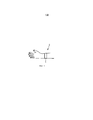
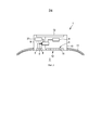
Фиг. 1 схематически и иллюстративно показывает вариант реализации устройства для определения физиологического показателя для определения физиологического показателя субъекта. В данном варианте реализации устройство 1 для определения физиологического показателя выполнено с возможностью ношения на запястье 2 субъекта. Более того, устройство для определения физиологического показателя выполнено с возможностью определения частоты пульса субъекта, как физиологического показателя. Устройство 1 для определения физиологического показателя схематически и иллюстративно показано на Фиг. 2 более подробно.FIG. 1 schematically and illustratively shows an embodiment of a device for determining a physiological index for determining a physiological index of a subject. In this embodiment, a
Устройство 1 для определения физиологического показателя содержит три источника 3, 4, 5 света для испускания лучей света с различными длинами волн на субъекта в области запястья 2. Лучи света проходят через часть запястья 2, в частности через ткань субъекта на запястье 2, при этом лучи света отражаются, например, тканью и кровью. Отраженный свет обнаруживается датчиком 6 света, имеющим двухмерную детектирующую поверхность 12, в зависимости от длины волны. Двухмерная детектирующая поверхность 12 содержит двухмерную схему размещения детектерных элементов 14, при этом каждый детектерный элемент 14 генерирует детектирующие сигналы, зависящие от длины волны, для генерирования двухмерного изображения, зависящего от длины волны. Датчик 6 света представляет собой, например, датчик с прибором зарядовой связи (ПЗС) или датчик на комплементарной структуре металл-оксид-полупроводник (КМОП). Он выполнен с возможностью генерирования трех двухмерных изображений для трех цветов, причем каждое изображение является временным изображением, т.е. они содержат несколько кадров изображения для разных моментов времени для указания на временные изменения детектирующих сигналов, которые используются модулем 9 определения физиологического показателя для определения физиологического показателя.The
Источники 3, 4, 5 света представляют собой, например, СИД. Однако они также могут быть другими типами источников света, такими как лазеры. В данном варианте реализации три источника 3, 4, 5 света выполнены с возможностью испускания луча синего света, луча зеленого света и луча красного света, соответственно, при этом каждый детектерный элемент выполнен с возможностью генерирования отдельных детектирующих сигналов для синего, зеленого и красного лучей соответственно. Таким образом, датчик 6 света содержит три цветовых канала, причем для каждого цветового канала генерируется двухмерное изображение на основе детектирующих сигналов, генерируемых для соответствующих цветов.
Устройство 1 для определения физиологического показателя дополнительно содержит контроллер 8 для раздельного управления интенсивностями лучей света разных источников 3, 4, 5 света. Контроллер 8, например, выполнен с возможностью раздельного управления интенсивностями лучей света разных источников 3, 4, 5 света таким образом, чтобы не допускать перегрузки датчика 6 света. В частности, датчик 6 света выполнен с возможностью предоставления сигнала перегрузки на контроллер 8, если цветовой канал детектерного элемента 14 перегружен, причем если контроллер 8 принимает такой сигнал перегрузки, контроллер 8 уменьшает интенсивность света соответствующего цвета, не допуская ситуации перегрузки. Таким образом, источниками 3, 4, 5 света можно управлять таким образом, что для каждого цвета детектирующей поверхности 12 принимается максимальное количество света без перегрузки какого-либо детектерного элемента 14 детектирующей поверхности 12.The
Поскольку детектирующие сигналы могут флюктуировать вследствие движения, контроллер 8 может быть выполнен с возможностью управления источниками 3, 4, 5 света таким образом, что детектирующая поверхность 12 принимает не максимальное количество света, что могло быть возможным без перегрузки датчика света, если возможные движения и, как следствие, соответствующие флуктуации в детектирующих сигналах не принимаются во внимание, а меньшее количество света. Разница между максимальным количеством и меньшим количеством может быть заранее определена или определяться для разных цветов контроллером 8. Она может соответствовать ожидаемой максимальной амплитуде флуктуации, обусловленной движением, интенсивности обнаруживаемого света. Например, контроллер 8 может быть выполнен с возможностью отличия флуктуаций сигнала, обусловленных физиологическим показателем, подлежащим измерению, от флуктуаций сигнала, вызванных движением, и управления источниками 3, 4, 5 света таким образом, чтобы не допускать перегрузки датчика 6 света, даже если имеют место флуктуации сигнала, обусловленные движением. Для определения ожидаемой максимальной амплитуды флуктуации, обусловленной движением, двухмерное изображение, т.е. образующие изображение детектирующие сигналы, может быть подвергнуто частотной фильтрации. Например, если известно, что физиологический показатель обуславливает флуктуации сигнала в пределах некоторого диапазона частот, могут наблюдаться флуктуации детектирующего сигнала за пределами этого диапазона частот и может определяться соответствующая максимальная амплитуда флуктуации детектирующего сигнала. Разница между максимальным количеством света и меньшим количеством света может соответствовать этой максимальной амплитуде. После того, как эта разница была определена, она может сохраняться в контроллере 8 и использоваться для дальнейших измерений. Управление интенсивностями света лучей света, испускаемых источниками 3, 4, 5 света, до меньшего количества света может обеспечить отсутствие прегрузки датчика 6 света, даже если интенсивности обнаруживаемого света флюктуируют вследствие движения.Since the detecting signals can fluctuate due to movement, the
Разница также может определяться другим способом. Например, модуль определения физиологического показателя может дополнительно содержать датчик 21 движения, такой как акселерометр, для генерирования сигнала движения, указывающего на движение устройства 1 для определения физиологического показателя, причем этот сигнал движения может использоваться контроллером 8 для отличия флуктуаций сигнала, обусловленных физиологическим показателем, подлежащим измерению, от флуктуаций сигнала, вызванных движением. В частности, сигнал движения может определять диапазон частот, в котором интенсивность обнаруженного света флюктуирует вследствие движения, причем максимальная амплитуда флуктуации интенсивности обнаруженного света в пределах этого диапазона может определять разницу между максимальным и меньшим количеством. Контроллер 8 также может быть выполнен с возможностью применения других технологий на основе корреляции для определения флуктуаций интенсивности света, вызываемых движением, путем корреляции детектирующего сигнала света с сигналом движения. Например, может определяться частота повторений сигнала движения, причем амплитуда детектирующего сигнала, флюктуирующегося с этой частотой повторений, может использоваться для определения разницы между максимальным количеством света и меньшим количеством света.The difference can also be determined in another way. For example, the physiological indicator determination module may further comprise a
Обычно, кровеносные сосуды, которые находятся глубже в коже, имеют больший диаметр, а кровь внутри этих кровеносных сосудов обладает более высоким кровяным давлением. Красный свет проникает относительно глубоко в кожу и обеспечивает, таким образом, относительно выраженную работу пульса в красном цветовом канале. Однако на соответствующий детектирующий сигнал также может влиять механическое движение устройства 1 для определения физиологического показателя. Зеленый свет проникает не так глубоко, как красный свет, но глубже, чем синий свет, который проникает по существу только лишь в первые слои кожи. Зеленый свет по-прежнему обеспечивает детектирующий сигнал, в котором работу пульса легко можно легко заметить, при этом, по сравнению с красным детектирующим сигналом, артефакты механического движения являются менее выраженными. В синем детектирующем сигнале работа пульса является наименее слабой, но кроме того, влияние артефактов механического движения, которые могут быть обсуловлены движением устройства для определения физиологического показателя, является относительно низким. Более того, детектирующий сигнал синего света может быть подвержен влиянию артефакта движения плескания, которое может быть обусловлено движением крови. Модуль 9 определения физиологического показателя, например, выполнен с возможностью использования детектирующих сигналов, которые генерируются с использованием красного, зеленого и синего света, и которые, таким образом, демонстрируют различные характеристики, для определения частоты пульса.Typically, blood vessels that are deeper in the skin have a larger diameter, and the blood inside these blood vessels has a higher blood pressure. Red light penetrates relatively deep into the skin and thus provides a relatively pronounced pulse rate in the red color channel. However, the mechanical movement of the
В частности, модуль 9 определения физиологического показателя выполнен с возможностью определения частоты пульса посредством независимой обработки детектирующих сигналов, генерируемых детектерными элементами 14 двухмерной детектирующей поверхности 12 для синего, зеленого и красного цветов. Кроме того, модуль определения физиологического показателя может быть выполнен с возможностью определения физиологического показателя путем определения, для разных групп детектерных элементов, групповых детектирующих сигналов, основанных на детектирующих сигналах, сгенерированных соответствующей группой детектерных элементов, и путем независимой обработки групповых детектирующих сигналов. Например, детектирующие сигналы группы детектерных элементов могут быть усреднены для определения группового детектирующего сигнала.In particular, the physiological
Модуль 9 определения физиологического показателя может быть выполнен с возможностью определения степени возмущения соответствующего детектирующего сигнала за счет движения и определения физиологического показателя на основе детектирующих сигналов, обладающих степенью возмущения меньшей, чем пороговая величина возмущения. Например, модуль 9 определения физиологического показателя может быть выполнен с возможностью определения степени возмущения соответствующего детектирующего сигнала на основе сигнала движения, генерируемого датчиком 21 движения. В частности, если частота повторений в сигнале движения подобна частоте повторений в детектирующем сигнале света, можно предположить, что детектирующий сигнал света сильно возмущен, тогда как, если частота повторений в сигнале движения не наблюдается или наблюдается слабо в детектирующем сигнале света, можно предположить, что возмущение отсутствует или имеет место только лишь слабое возмущение. Для определения степени возмущения для сигнала движения и соответствующего детектирующего сигнала света может вычисляться корреляция.
Детектирующие сигналы определяются для разных длин волн, т.е. цветов, и для разных местоположений на ткани, при этом возмущение детектирующих сигналов может отличаться для разных цветов и/или для разных местоположений соответствующего детектерного элемента. Среди этих детектирующих сигналов могут выбираться только детектирующие сигналы, которые только лишь слегка возмущены или вовсе не возмущены движением. Использование этих выбранных детектирующих сигналов для определения физиологического показателя может дополнительно улучшить это определение. Например, выбранные детектирующие сигналы могут быть комбинированы, в частности усреднены, а количество импульсов комбинированного выбранного детектирующего сигнала в минуту может определяться как частота пульса.Detecting signals are determined for different wavelengths, i.e. colors, and for different locations on the fabric, while the perturbation of the detecting signals may differ for different colors and / or for different locations of the corresponding detector element. Among these detecting signals, only detecting signals that are only slightly disturbed or not disturbed by the movement at all can be selected. The use of these selected detecting signals to determine a physiological index may further improve this determination. For example, the selected detection signals can be combined, in particular averaged, and the number of pulses of the combined selected detection signal per minute can be determined as the pulse rate.
В варианте реализации, модуль 9 определения физиологического показателя выполнен с возможностью определения физиологического показателя путем линейной комбинации детектирующих сигналов. В частности, модуль определения физиологического показателя может быть выполнен с возможностью линейного комбинирования детектирующих сигналов таким образом, что артефакты движения в линейно комбинированных детектирующих сигналах меньше, чем в детектирующих сигналах перед их линейной комбинацией. Например, модуль 9 определения физиологического показателя может быть выполнен с возможностью применения МГК к детектирующим сигналам для линейной комбинации детектирующих сигналов. Модуль 9 определения физиологического показателя затем может быть выполнен с возможностью определения физиологического показателя на основе линейно комбинированных сигналов, в частности на главной компоненте, полученной из МГК. Таким образом, линейная комбинация может «очищать» сигналы от артефактов движения, причем модуль 9 определения физиологического показателя может быть выполнен с возможностью определения частоты повторений очищенных детектирующих сигналов, как частоты пульса.In an embodiment, the physiological
Перед линейной комбинацией разных детектирующих сигналов света, детектирующие сигналы света могут взвешиваться, при этом детектирующие сигналы света, которые соответствуют областям ткани, в которых перфузия больше, могут получать больший вес, чем детектирующие сигналы света, которые соответствуют областям света, в которых перфузия меньше. Например, амплитуды детектирующих сигналов света, когда устройство для определения физиологического показателя находится в состоянии покоя, т.е. не двигается, используются как величины, указывающие на соответствующую величину перфузии. В варианте реализации это означает, например, что амплитуды детектирующих сигналов света определяются для каждого детектерного элемента и для каждой длины волны, при том, что устройство для определения физиологического показателя не двигается, причем затем, для каждой комбинации детектерного элемента и длины волны определяется вес, в зависимости от соответствующей амплитуды. Эти веса могут сохраняться и использоваться для определения физиологического показателя, в частности частоты пульса.Before a linear combination of different detecting light signals, the detecting light signals can be weighted, while the detecting light signals that correspond to tissue regions in which perfusion is greater can receive more weight than the detecting light signals that correspond to regions of light in which perfusion is less. For example, the amplitudes of the detecting light signals when the device for determining the physiological parameter is at rest, i.e. does not move, are used as values indicating the appropriate amount of perfusion. In an embodiment, this means, for example, that the amplitudes of the detecting light signals are determined for each detector element and for each wavelength, while the device for determining the physiological indicator does not move, and then, for each combination of the detector element and wavelength, the weight is determined, depending on the corresponding amplitude. These weights can be stored and used to determine the physiological indicator, in particular the pulse rate.
Модуль 9 определения физиологического показателя также может быть выполнен с возможностью определения соответствующих областей в разных кадрах изображения и определения физиологического показателя на основе этих соответствующих областей в разных кадрах изображения. Например, детектирующие сигналы, сгенерированные детектерными элементами 14 в пределах области в некотором кадре изображения, могут быть комбинированы, например, линейно комбинированы, как описано выше, или усреднены, для определения комбинированного сигнала для некоторого кадра изображения. Благодаря определению этого комбинированного сигнала для разных кадров изображения, может генерироваться зависящий от времени сигнал, который может использоваться модулем 9 определения физиологического показателя для определения физиологического показателя. Например, частота повторений зависящего от времени сигнала может определяться, как частота пульса. Для определения соответствующих областей в разных кадрах изображения могут использоваться известные технологии регистрации изображений, или другие известные технологии для выявления соответствующих элементов и, как следствие, областей в разных изображениях, которые могут быть основаны на корреляции.The physiological
Источниками 3, 4, 5 света можно управлять так, чтобы они работали в непрерывном режиме. Однако контроллер 8 также выполнен с возможностью управления источниками 3, 4, 5 света таким образом, что интенсивности лучей света изменяются. В частности, источники 3, 4, 5 света работают в импульсном режиме, в котором лучи света испускаются в ткань, как световые импульсы. Кроме того, контроллер 8 выполнен с возможностью управления источниками 3, 4, 5 света таким образом, что каждый источник 3, 4, 5 света циклически испускает по меньшей мере два импульса света с различными интенсивностями. Если интенсивность света относительно низка, в местах на двухмерной детектирующей поверхности 12 с относительно большим расстоянием до соответствующего источника 3, 4, 5 света интенсивность обнаруживаемого света может быть относительно низка или возможность измерения света даже может отсутствовать, вследствие относительно большого расстояния перемещения внутри ткани, тогда как в местах на двухмерной детектирующей поверхности 12 с относительно малым расстоянием до соответствующего источника 3, 4, 5 света свет может легко обнаруживаться без перегрузки детектерных элементов 14 в этом месте. Если интенсивность света относительно велика, в местах на двухмерной детектирующей поверхности 12 с относительно большим расстоянием до соответствующего источника 3, 4, 5 света свет может легко обнаруживаться, тогда как в местах на двухмерной детектирующей поверхности 12 с относительно малым расстоянием до соответствующего источника 3, 4, 5 света детектерные элементы 14 могут перегружаться. Модуль 9 определения физиологического показателя, например, выполнен с возможностью использования перегруженных детектирующих сигналов света и слишком слабых детектирующих сигналов света, т.е. детектирующих сигналов света, слабее, чем заранее заданное пороговое значение, которое может быть определено калибровкой, для определения частоты пульса. Это означает, что из детектирующих сигналов света, сгенерированных, когда интенсивности испущенного света были относительно низкими, используются, предпочтительно, только детектирующие сигналы света, которые были сгенерированы детектерными элементами 14, которые были относительно близки к источниками 3, 4, 5 света, тогда как из детектирующих сигналов света, сгенерированных, когда интенсивности испущенного света были относительно высокими, используются, предпочтительно, только детектирующие сигналы света, которые были сгенерированы детектерными элементами 14 с большим расстоянием до источников 3, 4, 5 света. Устройство 1 для определения физиологического показателя дополнительно содержит крепежный элемент 11 для прикрепления по меньшей мере источников 3, 4, 5 света и датчика 6 света к запястью 2 субъекта таким образом, что они располагаются непосредственно на коже запястья 2. В данном варианте реализации, крепежный элемент 11 представляет собой такой браслет, что устройство 1 для определения физиологического показателя представляет собой устройство, подобное наручным часам, которое выполнено с возможностью ношения на запястье 2 субъекта.
Устройство 1 для определения физиологического показателя может дополнительно содержать дисплей 13 для отображения определенного физиологического показателя. Более того, различные компоненты устройства 1 для определения физиологического показателя могут быть заключены в корпусе 10.The
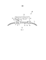
Фиг. 3 схематически и иллюстративно показывает еще один вариант реализации устройства для определения физиологического показателя. Устройство 20 для определения физиологического показателя, схематически и иллюстративно показанное на Фиг. 3, подобно устройству 1 для определения физиологического показателя, схематически и иллюстративно показанному на Фиг. 2, за исключением дополнительной проницаемой проставки 15, которая размещена между двухмерной детектирующей поверхностью 12 и запястьем 2. Толщина проставки 15, например, равна или больше 5 мм. Более того, в варианте реализации, схематически и иллюстративно показанном на Фиг. 3, три источника 4, 5, 6 света представляют собой, например, лазеры, испускающие когерентный свет, для обеспечения возможности генерирования двухмерных спекл-изображений датчиком 6 света. Проставка 15 выполнена проницаемой для длин волн лучей света, испускаемых источниками 3, 4, 5 света. Она может представлять собой проницаемую стеклянную пластину. Однако проставка также может быть выполнена из рассеивающего материала для увеличения контраста спеклов.FIG. 3 schematically and illustratively shows another embodiment of a device for determining a physiological index.
Кроме того, в данном варианте реализации, устройство для определения физиологического показателя, например, выполнено с возможностью определения частоты пульса субъекта, как физиологического показателя. В частности, в данном варианте реализации, модуль 9 определения физиологического показателя, например, выполнен с возможностью определения соответствующих областей в разных кадрах изображения и определения физиологического показателя на основе этих соответствующих областей в разных кадрах изображения. Например, детектирующие сигналы, генерируемые детектерными элементами 14 в пределах области в некотором кадре изображения, могут быть комбинированы, например, линейно комбинированы, как описано выше, или усреднены, для определения комбинированного сигнала для некоторого кадра изображения. Благодаря определению этого комбинированного сигнала для разных кадров изображения, может генерироваться зависящий от времени сигнал, который может использоваться модулем 9 определения физиологического показателя для определения физиологического показателя. Кроме того, возможно определять контраст в соответствующих областях в разных кадрах изображения, причем в этом случае контраст, определяемый для разных кадров изображения, образует временной сигнал, который может использоваться для определения частоты пульса.In addition, in this embodiment, a device for determining a physiological indicator, for example, is configured to determine the pulse rate of a subject as a physiological indicator. In particular, in this embodiment, the physiological
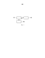
Далее в качестве примера будет описан вариант реализации способа определения физиологического показателя для определения физиологического показателя субъекта со ссылкой на блок-схему, изображенную на Фиг. 4.Next, as an example, an embodiment of a method for determining a physiological index for determining a physiological index of a subject will be described with reference to the flowchart shown in FIG. four.
На шаге 101 контроллер 8 управляет несколькими источниками 3, 4, 5 света таким образом, что они испускают несколько лучей света, обладающих различными длинами волн, в субъекта через запястье 2. Более того, контроллер 8 управляет датчиком 6 света для обнаружения света после того, как он прошел через запястье 2 субъекта, в зависимости от длины волны, и генерирования двухмерного изображения, зависящего от длины волны, т.е., например, трех двухмерных изображений для синего, зеленого и красного цветов, на основе обнаруженного света. На шаге 102, одновременно с шагом 101, для каждой длины волны определяется, перегружен ли датчик 6 света. Эта информация о перегрузке затем используется контроллером 8 для управления источниками 3, 4, 5 света таким образом, что интенсивности лучей света максимизируются без перегрузки дачика 6 света на любой длине волны. На шаге 103 модуль 9 определения физиологического показателя определяет физиологический показатель на основе сгенерированного двухмерного изображения, зависящего от длины волны, т.е., например, на основе трех двухмерных изображений, сгенерированных для синего, зеленого и красного цветов. Шаги 101-103 могут выполняться в цикле таким образом, что несколько лучей света циклически, например импульсным способом или непрерывно, испускаются в ткань субъекта и после прохождения через ткань обнаруживаются, при этом интенсивности света могут максимизироваться без перегрузки датчика, и причем модуль определения физиологического показателя может циклически определять физиологический показатель на основе циклически обнаруживаемого света, т.е. на основе циклически генерируемого двухмерного изображения, зависящего от длины волны.In
Под датчиком света может подразумеваться камера, которая вводится во взаимодействие с тканью на запястье субъекта для измерения частоты пульса, т.е. частоты сердечных сокращений, на запястье. Датчик света обнаруживает свет, который рассеялся в коже и который в большей или меньшей степени мог быть поглощен кровью. Детектирующие сигналы, генерируемые детектерными элементами двухмерной детектирующей поверхности, зависят от объема крови, поглотившей свет. При пульсации сердца, объем крови в крови изменяется и, таким образом, изменяются также и сигналы, генерируемые детектерными элементами двухмерной детектирующей поверхности. Устройство для определения физиологического показателя, описанное выше со ссылками на Фиг. 1-3, обеспечивает возможность достоверного определения частоты пульса на основе изменений детектирующих сигналов, генерируемых различными детектерными элементами двухмерной детектирующей поверхности, даже если запястье субъекта двигается.A light sensor may mean a camera, which is introduced into interaction with tissue on the wrist of a subject to measure the pulse rate, i.e. heart rate on the wrist. The light sensor detects light that is scattered in the skin and which to a greater or lesser extent could be absorbed by the blood. The detecting signals generated by the detector elements of the two-dimensional detecting surface depend on the volume of blood absorbing the light. With heart pulsation, the volume of blood in the blood changes and, thus, the signals generated by the detector elements of the two-dimensional detecting surface also change. The physiological indicator apparatus described above with reference to FIG. 1-3, provides the ability to reliably determine the heart rate based on changes in the detection signals generated by various detector elements of the two-dimensional detecting surface, even if the subject’s wrist is moving.
Детектирующий сигнал, генерируемый детектерным элементом, т.е. пикселем двухмерной детектирующей поверхности, зависит от расстояния детектерного элемента до соответствующего источника света. Если расстояние больше, то детектирующий сигнал в целом укажет на более низкую обнаруженную интенсивность, а если расстояние меньше, то детектирующий сигнал в целом укажет на более высокую обнаруженную интенсивность. Таким образом, за счет различия расстояний между а) детектерными элементами и b) источниками света, двухмерное изображение покажет изменения интенсивности в зависимости от расстояний. Эти изменения интенсивности имеют место, поскольку свет, обнаруженный детектерным элементом и имеющий большее расстояние до источника света, прошел через более глубокую и крупную часть ткани, чем свет, обнаруженный детектерным элементом, расположенным ближе к источникам света. Предполагается, что детектирующие сигналы, которые генерируются, основываясь на свете, пройденном через более глубокую и крупную часть ткани, обладают относительно сильным компонентом пульса, поскольку этот свет был сильнее подвергнут влиянию крови.The detection signal generated by the detector element, i.e. pixel of a two-dimensional detecting surface, depends on the distance of the detector element to the corresponding light source. If the distance is greater, then the detection signal as a whole will indicate a lower detected intensity, and if the distance is less, then the detection signal as a whole will indicate a higher detected intensity. Thus, due to the difference in the distances between a) the detector elements and b) the light sources, a two-dimensional image will show the intensity changes depending on the distances. These changes in intensity occur because the light detected by the detector element and having a greater distance to the light source passed through a deeper and larger part of the tissue than the light detected by the detector element located closer to the light sources. Detecting signals, which are generated based on the light transmitted through a deeper and larger part of the tissue, are believed to have a relatively strong component of the pulse, since this light was more strongly affected by blood.
Поскольку различные расстояния между детектерными элементами и источниками света, а также различными длинами волн, обеспечивают различные глубины проникновения обнаруживаемого света, двухмерное изображение предоставляет информацию о глубине резкости. Эта информация о глубине резкости используется устройством для определения физиологического показателя, описанным выше со ссылками на Фиг. 1-3, для достоверного определения физиологического показателя, даже если запястье субъекта, в частности рука субъекта, двигается.Since different distances between the detector elements and light sources, as well as different wavelengths, provide different penetration depths of the detected light, a two-dimensional image provides information about the depth of field. This depth of field information is used by the physiological index measuring apparatus described above with reference to FIG. 1-3, to reliably determine the physiological indicator, even if the wrist of the subject, in particular the hand of the subject, moves.
Датчик света может быть выполнен с возможностью генерирования соответствующего первого изображения, когда источники света не испускают свет, и второго соответствующего изображения, когда источники света испускают свет, причем первое и второе изображения могут вычитаться друг из друга и при этом соответствующее изображение, полученное в результате вычитания, может использоваться для дальнейшей обработки. Использование таких изображений, полученных в результате вычитания, которые могут генерироваться для разных моментов времени, для обработки может в результате обеспечить уменьшение артефактов окружающих условий, генерируемых окружающим освещением, которые могут присутствовать. Более того, устройство для определения физиологического показателя может содержать модуль определения отношения сигнал/шум для определения отношений сигнал/шум, зависящих от длины волны, для обнаружения света, зависящего от длины волны. Таким образом, например, для каждого из трех цветов отношение сигнал/шум может определяться для соответствующего двухмерного изображения, при этом контроллер может быть выполнен с возможностью раздельного управления разными источниками света в зависимости от соответствующих определенных отношений сигнал/шум, в частности так, что отношение сигнал/шум раздельно оптимизируется для каждой длины волны без перегрузки датчика. Отношение сигнал/шум может зависеть от электронного шума и/или движений устройства для определения физиологического показателя.The light sensor can be configured to generate a corresponding first image when the light sources do not emit light, and a second corresponding image when the light sources emit light, the first and second images can be subtracted from each other and the corresponding image obtained by subtraction , can be used for further processing. The use of such images obtained by subtraction, which can be generated for different points in time, for processing, can result in a reduction of environmental artifacts generated by the ambient lighting that may be present. Moreover, a device for determining a physiological parameter may include a signal-to-noise ratio determination module for determining signal-to-noise ratios dependent on a wavelength, for detecting light dependent on a wavelength. Thus, for example, for each of the three colors, the signal-to-noise ratio can be determined for the corresponding two-dimensional image, while the controller can be configured to separately control different light sources depending on the corresponding certain signal-to-noise ratios, in particular so that the ratio S / N is separately optimized for each wavelength without overloading the sensor. The signal-to-noise ratio may depend on electronic noise and / or the movements of the device to determine the physiological index.
Устройство для определения физиологического показателя содержит, например, три источника света с оптимизированной производительностью и энергопотреблением, при этом эти три источника света, например, выполнены с возможностью испускания синего, зеленого и красного света. Посредством изменения мощности каждого из этих трех источников света, т.е. посредством изменения интенсивности соответствующих лучей света, отношение сигнал/шум в каждом цветовом канале датчика света может оптимизироваться без перегрузки датчика света. Если источники света представляют собой лазеры, между датчиком света и кожей субъекта, предпочтительно, размещается оптически проницаемая проставка. Устройство для определения физиологического показателя, например, выполнено с возможностью получения преимущества от разниц между расстояниями разных детектерных элементов, т.е. пикселей, до трех источников света, при этом детектирующие сигналы, генерируемые различными детектерными элементами, например, независимо обрабатываются для определения физиологического показателя.A device for determining a physiological index contains, for example, three light sources with optimized performance and energy consumption, while these three light sources, for example, are configured to emit blue, green and red light. By changing the power of each of these three light sources, i.e. by changing the intensity of the respective light beams, the signal-to-noise ratio in each color channel of the light sensor can be optimized without overloading the light sensor. If the light sources are lasers, an optically permeable spacer is preferably placed between the light sensor and the skin of the subject. A device for determining a physiological indicator, for example, is configured to take advantage of the differences between the distances of different detector elements, i.e. pixels, up to three light sources, while the detecting signals generated by various detector elements, for example, are independently processed to determine a physiological index.
Несмотря на то, что в вышеописанных вариантах реализации для генерирования трех разных лучей света с различными длинами волн, т.е. разных цветов, были использованы три источника света, в других вариантах реализации два или более трех источников света могут использоваться для генерирования двух или более трех лучей света разных цветов. Более того, несмотря на то, что в вышеописанных вариантах реализации это три источника света испускают лучи синего, зеленого и красного света, в других вариантах реализации источники свтеа могут испускать лучи света других цветов.Despite the fact that in the above embodiments for generating three different rays of light with different wavelengths, i.e. different colors, three light sources were used, in other embodiments, two or more than three light sources can be used to generate two or more three light rays of different colors. Moreover, despite the fact that in the above-described embodiments, these three light sources emit blue, green, and red light, in other embodiments, the light sources may emit light of different colors.
Несмотря на то, что в вышеописанных вариантах реализации устройство для определения физиологического показателя выполнено с возможностью определения частоты пульса как физиологического показателя, в других вариантах реализации устройство для определения физиологического показателя может быть выполнено с возможностью определения другого физиологического показателя на основе двухмерных изображений, такого как насыщение крови кислородом, причем, если устройство для определения физиологического показателя выполнено с возможностью определения насыщения крови кислородом, то используются, например, по меньшей мере два источника света, испускающие красный и зеленый свет.Despite the fact that in the above embodiments, the device for determining the physiological indicator is configured to determine the pulse rate as a physiological indicator, in other embodiments, the device for determining the physiological indicator can be configured to determine another physiological indicator based on two-dimensional images, such as saturation blood oxygen, and if the device for determining the physiological indicator is made with the possibility determining blood oxygen saturation, then at least two light sources emitting red and green light are used, for example.
Несмотря на то, что в вышеописанных вариантах реализации устройство для определения физиологического показателя выполнено с возможностью ношения на запястье субъекта, для определения физиологического показателя на запястье, в других вариантах реализации устройство для определения физиологического показателя может быть выполнено с возможностью определения физиологического показателя в другой части тела субъекта, такой как палец, рука, нога, грудь и так далее.Despite the fact that in the above embodiments, the device for determining the physiological indicator is made to be worn on the wrist of the subject, to determine the physiological indicator on the wrist, in other embodiments, the device for determining the physiological indicator can be configured to determine the physiological indicator in another part of the body a subject, such as a finger, arm, leg, chest, and so on.
Другие изменения раскрытых вариантов могут быть поняты и реализованы специалистами в данной области техники при практическом внедрении заявленного изобретения в результате изучения чертежей, описания и приложенной формулы изобретения.Other changes to the disclosed options can be understood and implemented by specialists in this field of technology in the practical implementation of the claimed invention as a result of a study of the drawings, description and appended claims.
В формуле изобретения термин «содержащий» не исключает других элементов или шагов, а формы единственного числа, выраженные неопределенными артиклями "a" или "an" не исключают множество.In the claims, the term “comprising” does not exclude other elements or steps, and the singular forms expressed by the indefinite articles “a” or “an” do not exclude a plurality.
Один модуль или устройство могут выполнять функции двух или более элементов, изложенные в формуле изобретения. Сам по себе тот факт, что определенные средства упомянуты в отличных друг от друга зависимых пунктах формулы изобретения, не означает, что комбинация этих средств не может быть использована для получения преимуществ.One module or device may fulfill the functions of two or more elements set forth in the claims. The mere fact that certain agents are mentioned in different dependent claims does not mean that a combination of these agents cannot be used to take advantage.
Такие процедуры, как определение физиологического показателя, управление источниками света и так далее, выполняемые одним или более модулями или устройствами, могут выполняться любым другим количеством модулей или устройств. Эти процедуры и управление устройством для определения физиологического показателя, в соответствии со способом определения физиологического показателя, могут быть реализованы в виде программных средств компьютерной программы и/или в качестве специализированного аппаратного средства.Procedures such as determining a physiological indicator, controlling light sources, and so on, performed by one or more modules or devices, may be performed by any other number of modules or devices. These procedures and the control of a device for determining a physiological indicator, in accordance with the method for determining a physiological indicator, can be implemented in the form of software of a computer program and / or as a specialized hardware.
Компьютерная программа может быть сохранена/распределена на подходящем (энергонезависимом) носителе, таком как оптический носитель записи или твердотельный носитель, поставленный вместе с аппаратными средствами или в качестве их части, однако она может также быть распределена и в других формах, например через Интернет или другие проводные или беспроводные телекоммуникационные системы.A computer program can be stored / distributed on a suitable (non-volatile) medium, such as an optical recording medium or solid-state medium, supplied with the hardware or as part of it, but it can also be distributed in other forms, for example via the Internet or other wired or wireless telecommunication systems.
Любые ссылочные обозначения в формуле изобретения не должны рассматриваться как ограничивающие объем изобретения.Any reference signs in the claims should not be construed as limiting the scope of the invention.
Claims (28)
Applications Claiming Priority (3)
| Application Number | Priority Date | Filing Date | Title |
|---|---|---|---|
| EP14158128.0 | 2014-03-06 | ||
| EP14158128 | 2014-03-06 | ||
| PCT/EP2015/053037 WO2015132063A1 (en) | 2014-03-06 | 2015-02-13 | Physiological property determination apparatus |
Publications (3)
| Publication Number | Publication Date |
|---|---|
| RU2016139135A RU2016139135A (en) | 2018-04-09 |
| RU2016139135A3 RU2016139135A3 (en) | 2018-10-19 |
| RU2684560C2 true RU2684560C2 (en) | 2019-04-09 |
Family
ID=50239425
Family Applications (1)
| Application Number | Title | Priority Date | Filing Date |
|---|---|---|---|
| RU2016139135A RU2684560C2 (en) | 2014-03-06 | 2015-02-13 | Physiological property determination device |
Country Status (7)
| Country | Link |
|---|---|
| US (1) | US11134854B2 (en) |
| EP (1) | EP3113670B1 (en) |
| JP (1) | JP6526694B2 (en) |
| CN (1) | CN106102564B (en) |
| BR (1) | BR112016020283B1 (en) |
| RU (1) | RU2684560C2 (en) |
| WO (1) | WO2015132063A1 (en) |
Families Citing this family (8)
| Publication number | Priority date | Publication date | Assignee | Title |
|---|---|---|---|---|
| EP2326239B1 (en) | 2008-07-03 | 2017-06-21 | Masimo Laboratories, Inc. | Protrusion for improving spectroscopic measurement of blood constituents |
| US8203704B2 (en) | 2008-08-04 | 2012-06-19 | Cercacor Laboratories, Inc. | Multi-stream sensor for noninvasive measurement of blood constituents |
| US10448871B2 (en) | 2015-07-02 | 2019-10-22 | Masimo Corporation | Advanced pulse oximetry sensor |
| JP6928906B2 (en) * | 2016-01-07 | 2021-09-01 | パナソニックIpマネジメント株式会社 | Biological information measuring device |
| KR101842771B1 (en) * | 2016-06-10 | 2018-03-28 | 전자부품연구원 | MSP-based Horizontal-Vertical Biometric Device and Method |
| CN109890278B (en) * | 2016-10-27 | 2023-04-04 | 皇家飞利浦有限公司 | Device, system and method for obtaining vital signals of an object |
| JP7161704B2 (en) * | 2019-03-29 | 2022-10-27 | 株式会社アイシン | Pulse rate detector and pulse rate detection program |
| CN111311466B (en) * | 2020-01-23 | 2024-03-19 | 深圳市大拿科技有限公司 | Safety control method and device |
Citations (4)
| Publication number | Priority date | Publication date | Assignee | Title |
|---|---|---|---|---|
| SU888931A1 (en) * | 1978-07-11 | 1981-12-15 | Ленинградский Ордена Ленина Электротехнический Институт Им. В.И.Ульянова (Ленина) | Photopletismograph |
| US20070299330A1 (en) * | 2006-05-24 | 2007-12-27 | Robert Couronne | Sensor, processing means, method and computer program for providing information on a vital parameter of a living being |
| US20090306487A1 (en) * | 2006-04-11 | 2009-12-10 | The University Of Nottingham | Photoplethysmography |
| US20130030307A1 (en) * | 2011-07-28 | 2013-01-31 | Vinayakrishnan Rajan | Quantifying laser-doppler perfusion signal for arrhythmia detection and disease monitoring |
Family Cites Families (26)
| Publication number | Priority date | Publication date | Assignee | Title |
|---|---|---|---|---|
| JP4752673B2 (en) | 2005-10-06 | 2011-08-17 | コニカミノルタセンシング株式会社 | Pulse wave data analysis method, system, program |
| EP2074552A1 (en) * | 2006-09-29 | 2009-07-01 | Koninklijke Philips Electronics N.V. | Template synthesis for ecg/ppg based biometrics |
| JP5374835B2 (en) | 2007-06-06 | 2013-12-25 | セイコーエプソン株式会社 | Biological information measuring apparatus and control method thereof |
| JP5060186B2 (en) | 2007-07-05 | 2012-10-31 | 株式会社東芝 | Pulse wave processing apparatus and method |
| US20090203998A1 (en) | 2008-02-13 | 2009-08-13 | Gunnar Klinghult | Heart rate counter, portable apparatus, method, and computer program for heart rate counting |
| US20090226071A1 (en) | 2008-03-06 | 2009-09-10 | Motorola, Inc. | Method and Apparatus to Facilitate Using Visible Light Images to Determine a Heart Rate |
| EP3357419A1 (en) * | 2009-02-25 | 2018-08-08 | Valencell, Inc. | Light-guiding devices and monitoring devices incorporating same |
| US20100268094A1 (en) | 2009-04-15 | 2010-10-21 | Oceanit Laboratories Inc. | Consumer electronic camera photoplethysmograph |
| US8868149B2 (en) * | 2009-07-30 | 2014-10-21 | Oxitone Medical Ltd. | Photoplethysmography device and method |
| US8634591B2 (en) | 2009-08-20 | 2014-01-21 | Koninklijke Philips N.V. | Method and system for image analysis |
| FR2949658B1 (en) | 2009-09-07 | 2012-07-27 | Salim Mimouni | OPTICAL PLETHYSMOGRAPHIC SIGNAL CAPTURE DEVICE USING MATRIX IMAGER |
| US8666116B2 (en) | 2009-10-06 | 2014-03-04 | Koninklijke Philips N.V. | Method and system for obtaining a first signal for analysis to characterize at least one periodic component thereof |
| JP5012941B2 (en) | 2010-03-26 | 2012-08-29 | カシオ計算機株式会社 | Biological information measuring device |
| US10687706B2 (en) * | 2011-08-01 | 2020-06-23 | Koninklijke Philips N.V. | Device and method for obtaining and processing measurement readings including at least a component representative of a physical phenomenon in a living being |
| GB2494622A (en) | 2011-08-30 | 2013-03-20 | Oxitone Medical Ltd | Wearable pulse oximetry device |
| WO2013030745A1 (en) * | 2011-09-02 | 2013-03-07 | Koninklijke Philips Electronics N.V. | Camera for generating a biometrical signal of a living being |
| US10393839B2 (en) * | 2012-02-03 | 2019-08-27 | Arizona Board Of Regents On Behalf Of The University Of Arizona | System and method for image processing with highly undersampled imaging data |
| US9848787B2 (en) * | 2012-02-07 | 2017-12-26 | Laser Associated Sciences, Inc. | Perfusion assessment using transmission laser speckle imaging |
| WO2013128345A1 (en) * | 2012-02-28 | 2013-09-06 | Koninklijke Philips N.V. | Device and method for monitoring vital signs |
| JP2013208312A (en) * | 2012-03-30 | 2013-10-10 | Seiko Epson Corp | Signal analyzer, electronic equipment and program |
| CN104203089B (en) | 2012-03-30 | 2016-05-04 | 精工爱普生株式会社 | Pulsation detector and electronic equipment |
| JP5404968B1 (en) * | 2012-03-30 | 2014-02-05 | オリンパスメディカルシステムズ株式会社 | Endoscope device |
| CN202981974U (en) | 2012-06-01 | 2013-06-12 | 上海中医药大学 | Wearable vital sign detection apparatus |
| BR112015001773A2 (en) * | 2012-07-30 | 2017-07-04 | Koninklijke Philips Nv | device for extracting physiological information from electromagnetic radiation emitted or reflected by an individual, method for extracting physiological information from electromagnetic radiation emitted or reflected by an individual, and computer program |
| US9662022B2 (en) * | 2013-04-26 | 2017-05-30 | Xerox Corporation | Continuous cardiac signal generation from a video of a subject being monitored for cardiac function |
| US10506960B2 (en) * | 2013-07-10 | 2019-12-17 | Koninklijke Philips N.V. | System for screening of the state of oxygenation of a subject |
-
2015
- 2015-02-13 WO PCT/EP2015/053037 patent/WO2015132063A1/en active Application Filing
- 2015-02-13 US US15/116,116 patent/US11134854B2/en active Active
- 2015-02-13 EP EP15706184.7A patent/EP3113670B1/en active Active
- 2015-02-13 JP JP2016555278A patent/JP6526694B2/en active Active
- 2015-02-13 CN CN201580012198.8A patent/CN106102564B/en active Active
- 2015-02-13 BR BR112016020283-0A patent/BR112016020283B1/en active IP Right Grant
- 2015-02-13 RU RU2016139135A patent/RU2684560C2/en active
Patent Citations (4)
| Publication number | Priority date | Publication date | Assignee | Title |
|---|---|---|---|---|
| SU888931A1 (en) * | 1978-07-11 | 1981-12-15 | Ленинградский Ордена Ленина Электротехнический Институт Им. В.И.Ульянова (Ленина) | Photopletismograph |
| US20090306487A1 (en) * | 2006-04-11 | 2009-12-10 | The University Of Nottingham | Photoplethysmography |
| US20070299330A1 (en) * | 2006-05-24 | 2007-12-27 | Robert Couronne | Sensor, processing means, method and computer program for providing information on a vital parameter of a living being |
| US20130030307A1 (en) * | 2011-07-28 | 2013-01-31 | Vinayakrishnan Rajan | Quantifying laser-doppler perfusion signal for arrhythmia detection and disease monitoring |
Also Published As
| Publication number | Publication date |
|---|---|
| CN106102564B (en) | 2019-10-01 |
| US20170172435A1 (en) | 2017-06-22 |
| WO2015132063A1 (en) | 2015-09-11 |
| BR112016020283A2 (en) | 2017-08-15 |
| BR112016020283B1 (en) | 2022-07-12 |
| CN106102564A (en) | 2016-11-09 |
| EP3113670B1 (en) | 2020-05-27 |
| RU2016139135A3 (en) | 2018-10-19 |
| JP2017507724A (en) | 2017-03-23 |
| RU2016139135A (en) | 2018-04-09 |
| US11134854B2 (en) | 2021-10-05 |
| EP3113670A1 (en) | 2017-01-11 |
| JP6526694B2 (en) | 2019-06-05 |
Similar Documents
| Publication | Publication Date | Title |
|---|---|---|
| RU2684560C2 (en) | Physiological property determination device | |
| CN104968259B (en) | System and method for the vital sign information for determining object | |
| US9204843B2 (en) | Optical distance measurement system and operation method thereof | |
| RU2649529C2 (en) | Device and method for obtaining vital sign information of a living being | |
| RU2680190C1 (en) | Sensor of indicators of vital important functions and method of measurement of indicators of vital life important functions of user | |
| US10499821B2 (en) | Optical heart rate sensor | |
| TW201606331A (en) | Optoelectronic modules operable to distinguish between signals indicative of reflections from an object of interest and signals indicative of a spurious reflection | |
| US20130072771A1 (en) | Optical finger mouse, electronic device and physiological characteristics detection device | |
| WO2014141084A1 (en) | Device and method for determining vital signs of a subject | |
| US20130127721A1 (en) | Optical finger mouse, mouse control module and physiology detection method thereof | |
| US10159418B2 (en) | Information obtaining apparatus, image capturing apparatus, and method for obtaining information | |
| US20170071489A1 (en) | Heart rate monitor system | |
| RU2013136548A (en) | DEVICE FOR SCANNING A BARCODE FOR DETERMINING THE PHYSIOLOGICAL PARAMETER OF A PATIENT | |
| US10034639B2 (en) | Optical vital signs sensor | |
| JP2017507724A5 (en) | ||
| US10477119B2 (en) | Imaging device | |
| US20160317004A1 (en) | Imaging apparatus | |
| WO2018146055A1 (en) | Optical sensing apparatus and corresponding optical sensing method | |
| CN115135231A (en) | Device, system and method for determining vital signs of a subject | |
| WO2022044718A1 (en) | Device and method for measuring muscle oxygen consumption, and computer program | |
| CN210784322U (en) | Wearable device and physiological parameter monitoring module thereof |