RU2667724C2 - Sleep apnea diagnostic system and method for forming information with use of nonintrusive analysis of audio signals - Google Patents
Sleep apnea diagnostic system and method for forming information with use of nonintrusive analysis of audio signals Download PDFInfo
- Publication number
- RU2667724C2 RU2667724C2 RU2015129091A RU2015129091A RU2667724C2 RU 2667724 C2 RU2667724 C2 RU 2667724C2 RU 2015129091 A RU2015129091 A RU 2015129091A RU 2015129091 A RU2015129091 A RU 2015129091A RU 2667724 C2 RU2667724 C2 RU 2667724C2
- Authority
- RU
- Russia
- Prior art keywords
- information
- audio
- head
- beam former
- audio information
- Prior art date
Links
Images
Classifications
-
- A—HUMAN NECESSITIES
- A61—MEDICAL OR VETERINARY SCIENCE; HYGIENE
- A61B—DIAGNOSIS; SURGERY; IDENTIFICATION
- A61B5/00—Measuring for diagnostic purposes; Identification of persons
- A61B5/48—Other medical applications
- A61B5/4806—Sleep evaluation
- A61B5/4818—Sleep apnoea
-
- A—HUMAN NECESSITIES
- A61—MEDICAL OR VETERINARY SCIENCE; HYGIENE
- A61B—DIAGNOSIS; SURGERY; IDENTIFICATION
- A61B5/00—Measuring for diagnostic purposes; Identification of persons
- A61B5/08—Detecting, measuring or recording devices for evaluating the respiratory organs
- A61B5/087—Measuring breath flow
-
- A—HUMAN NECESSITIES
- A61—MEDICAL OR VETERINARY SCIENCE; HYGIENE
- A61B—DIAGNOSIS; SURGERY; IDENTIFICATION
- A61B5/00—Measuring for diagnostic purposes; Identification of persons
- A61B5/103—Detecting, measuring or recording devices for testing the shape, pattern, colour, size or movement of the body or parts thereof, for diagnostic purposes
- A61B5/11—Measuring movement of the entire body or parts thereof, e.g. head or hand tremor, mobility of a limb
-
- A—HUMAN NECESSITIES
- A61—MEDICAL OR VETERINARY SCIENCE; HYGIENE
- A61B—DIAGNOSIS; SURGERY; IDENTIFICATION
- A61B5/00—Measuring for diagnostic purposes; Identification of persons
- A61B5/72—Signal processing specially adapted for physiological signals or for diagnostic purposes
- A61B5/7203—Signal processing specially adapted for physiological signals or for diagnostic purposes for noise prevention, reduction or removal
- A61B5/7207—Signal processing specially adapted for physiological signals or for diagnostic purposes for noise prevention, reduction or removal of noise induced by motion artifacts
-
- A—HUMAN NECESSITIES
- A61—MEDICAL OR VETERINARY SCIENCE; HYGIENE
- A61B—DIAGNOSIS; SURGERY; IDENTIFICATION
- A61B7/00—Instruments for auscultation
- A61B7/003—Detecting lung or respiration noise
-
- H—ELECTRICITY
- H04—ELECTRIC COMMUNICATION TECHNIQUE
- H04R—LOUDSPEAKERS, MICROPHONES, GRAMOPHONE PICK-UPS OR LIKE ACOUSTIC ELECTROMECHANICAL TRANSDUCERS; DEAF-AID SETS; PUBLIC ADDRESS SYSTEMS
- H04R1/00—Details of transducers, loudspeakers or microphones
- H04R1/08—Mouthpieces; Microphones; Attachments therefor
-
- H—ELECTRICITY
- H04—ELECTRIC COMMUNICATION TECHNIQUE
- H04R—LOUDSPEAKERS, MICROPHONES, GRAMOPHONE PICK-UPS OR LIKE ACOUSTIC ELECTROMECHANICAL TRANSDUCERS; DEAF-AID SETS; PUBLIC ADDRESS SYSTEMS
- H04R3/00—Circuits for transducers, loudspeakers or microphones
- H04R3/005—Circuits for transducers, loudspeakers or microphones for combining the signals of two or more microphones
-
- A—HUMAN NECESSITIES
- A61—MEDICAL OR VETERINARY SCIENCE; HYGIENE
- A61B—DIAGNOSIS; SURGERY; IDENTIFICATION
- A61B2562/00—Details of sensors; Constructional details of sensor housings or probes; Accessories for sensors
- A61B2562/04—Arrangements of multiple sensors of the same type
-
- H—ELECTRICITY
- H04—ELECTRIC COMMUNICATION TECHNIQUE
- H04R—LOUDSPEAKERS, MICROPHONES, GRAMOPHONE PICK-UPS OR LIKE ACOUSTIC ELECTROMECHANICAL TRANSDUCERS; DEAF-AID SETS; PUBLIC ADDRESS SYSTEMS
- H04R1/00—Details of transducers, loudspeakers or microphones
- H04R1/20—Arrangements for obtaining desired frequency or directional characteristics
- H04R1/32—Arrangements for obtaining desired frequency or directional characteristics for obtaining desired directional characteristic only
- H04R1/40—Arrangements for obtaining desired frequency or directional characteristics for obtaining desired directional characteristic only by combining a number of identical transducers
- H04R1/406—Arrangements for obtaining desired frequency or directional characteristics for obtaining desired directional characteristic only by combining a number of identical transducers microphones
-
- H—ELECTRICITY
- H04—ELECTRIC COMMUNICATION TECHNIQUE
- H04R—LOUDSPEAKERS, MICROPHONES, GRAMOPHONE PICK-UPS OR LIKE ACOUSTIC ELECTROMECHANICAL TRANSDUCERS; DEAF-AID SETS; PUBLIC ADDRESS SYSTEMS
- H04R2410/00—Microphones
- H04R2410/01—Noise reduction using microphones having different directional characteristics
-
- H—ELECTRICITY
- H04—ELECTRIC COMMUNICATION TECHNIQUE
- H04R—LOUDSPEAKERS, MICROPHONES, GRAMOPHONE PICK-UPS OR LIKE ACOUSTIC ELECTROMECHANICAL TRANSDUCERS; DEAF-AID SETS; PUBLIC ADDRESS SYSTEMS
- H04R2430/00—Signal processing covered by H04R, not provided for in its groups
- H04R2430/20—Processing of the output signals of the acoustic transducers of an array for obtaining a desired directivity characteristic
- H04R2430/23—Direction finding using a sum-delay beam-former
Abstract
Description
ОБЛАСТЬ ТЕХНИКИ, К КОТОРОЙ ОТНОСИТСЯ ИЗОБРЕТЕНИЕFIELD OF THE INVENTION
Настоящее изобретение относится к диагностике апноэ во сне и, в частности, к системе и способу диагностики апноэ во сне.The present invention relates to the diagnosis of sleep apnea and, in particular, to a system and method for diagnosing sleep apnea.
УРОВЕНЬ ТЕХНИКИBACKGROUND
Обструктивное апноэ во сне (OSA) представляет собой состояние, которое вредит миллионам людей по всему миру. Состояние OSA характеризуется нарушениями или остановкой дыхания во время сна. Эпизоды OSA происходят от частичной или полной блокады потока воздуха во время сна, которая продолжается, по меньшей мере, 10 секунд и, чаще, от 1 до 2 минут. В течение определенной ночи, люди со степенью апноэ от средней до тяжелой могут испытывать полные или частичные перерывы дыхания до 200-500 за ночь. Поскольку их сон постоянно прерывается, они лишены восстановительного сна, необходимого для эффективного функционирования тела и психики. Данное расстройство сна связывали также с гипертензией, депрессией, инсультом, аритмиями сердца, инфарктом миокарда и другими сердечно-сосудистыми расстройствами. Состояние OSA вызывает также чрезмерную усталость.Obstructive sleep apnea (OSA) is a condition that harms millions of people around the world. OSA is characterized by disturbances or respiratory failure during sleep. OSA episodes occur from a partial or complete blockage of airflow during sleep, which lasts at least 10 seconds and, more often, from 1 to 2 minutes. During a particular night, people with moderate to severe apnea may experience complete or partial respiratory breaks of up to 200-500 per night. Since their sleep is constantly interrupted, they are deprived of the restorative sleep necessary for the effective functioning of the body and psyche. This sleep disorder has also been associated with hypertension, depression, stroke, cardiac arrhythmias, myocardial infarction, and other cardiovascular disorders. An OSA condition also causes excessive fatigue.
Для оценки того, страдает ли пациент от OSA, применяли различные способы. Наиболее исчерпывающим способом является клиническая полисомнограмма (PSG), которая может диагностировать много значительных патологий сна. Однако, PSG требует пребывание в течение ночи в специальном больничном учреждении или центре лечения расстройств сна, в присутствии специалистов для контроля как оборудования, так пациента.Various methods have been used to assess whether a patient suffers from OSA. The most comprehensive method is clinical polysomnogram (PSG), which can diagnose many significant sleep pathologies. However, PSG requires an overnight stay in a special hospital facility or sleep disorder treatment center, in the presence of specialists to monitor both equipment and the patient.
Устройства для домашнего применения, которые измеряют и объединяют насыщение кислородом крови, частоту пульса, поток воздуха, интенсивность храпения и движения головой, также применялись для оценки апноэ во сне. Хотя данные устройства менее дороги, чем PSG, устройства по-прежнему являются слишком дорогими и причиняющими неудобство (в дальнейшем, навязчивыми).Home use devices that measure and combine blood oxygen saturation, heart rate, air flow, snoring intensity, and head movements have also been used to evaluate sleep apnea. Although these devices are less expensive than PSGs, the devices are still too expensive and inconvenient (hereinafter, intrusive).
Анкеты и тесты также использовались для оценки апноэ во сне. Однако, хотя анкеты и тесты бесплатны и легко собираются, их точность при оценке апноэ во сне очень ограничена.Questionnaires and tests were also used to evaluate sleep apnea. However, although questionnaires and tests are free and easy to assemble, their accuracy in assessing sleep apnea is very limited.
Для оценки апноэ во сне использовали также аудиозапись. Хотя аудиозапись можно получать дешево и ненавязчиво, аудиозапись чувствительна к шумам, например, окружающему шуму, храпу супруга или другим шумам, что снижает точность метода.An audio recording was also used to evaluate sleep apnea. Although audio recordings can be obtained cheaply and unobtrusively, audio recordings are sensitive to noise, such as ambient noise, spouse snoring, or other noise, which reduces the accuracy of the method.
Соответственно, существует потребность в совершенствовании оценки апноэ во сне и, например, в недорогом и ненавязчивом способе точной оценки апноэ во сне.Accordingly, there is a need to improve the assessment of sleep apnea and, for example, in an inexpensive and unobtrusive way to accurately assess sleep apnea.
Раскрытие изобретения В одном варианте осуществления предлагается электронное устройство, которое включает в себя решетку микрофонов для регистрации слышимых звуков, производимых пациентом, и для формирования аудиоинформации, представляющей регистрируемые слышимые звуки, производимые пациентом, первый формирователь пучка, имеющий первое адаптационное быстродействие и сконфигурированный с возможностью формирования первой аудиоинформации и первой информации шумов из аудиоинформации, второй формирователь пучка, имеющий второе адаптационное быстродействие, которое медленнее, чем первое адаптационное быстродействие, при этом второй формирователь пучка сконфигурирован с возможностью формирования второй аудиоинформации и второй информации шумов из аудиоинформации, блок классификации аудио для формирования информации о классификации аудио на основании первой аудиоинформации, блок обнаружения движений головы для формирования информации о движениях головы на основании, по меньшей мере, какой-то одной из второй аудиоинформации, первой информации шумов и второй информации шумов и диагностический блок для установления диагноза по поводу апноэ во сне на основании информации о классификации аудио и информации о движениях головы.SUMMARY OF THE INVENTION In one embodiment, an electronic device is provided that includes an array of microphones for recording audible sounds produced by a patient and for generating audio information representing recorded audible sounds made by the patient, a first beam former having a first adaptive speed and configured to form first audio information and first noise information from audio information, a second beam former having a second hell random performance, which is slower than the first adaptive performance, while the second beam former is configured to generate second audio information and second noise information from the audio information, an audio classification unit for generating audio classification information based on the first audio information, a head movement detection unit for generating information about head movements based on at least one of the second audio information, the first noise information and the second deformations of noise and a diagnostic unit for diagnosing about sleep apnea based on the classification information and audio information on the movements of the head.
В другом варианте осуществления предлагается способ формирования информации о классификации аудио и информации о движениях головы, который включает в себя регистрацию слышимых звуков, производимых пациентом, решеткой микрофонов и формирование аудиоинформации, представляющей регистрируемые слышимые звуки, производимые пациентом, обработку аудиоинформации первым формирователем пучка, имеющим первое адаптационное быстродействие и формирующим первую аудиоинформацию и первую информацию шумов из аудиоинформации, обработку аудиоинформации вторым формирователем пучка, имеющим второе адаптационное быстродействие, которое медленнее, чем первое адаптационное быстродействие, и формирующим вторую аудиоинформацию и вторую информацию шумов из аудиоинформации, формирование информации о классификации аудио на основании первой аудиоинформации и формирование информации о движениях головы на основании, по меньшей мере, какой-то одной из второй аудиоинформации, первой информации шумов и второй информации шумов.In another embodiment, a method for generating audio classification information and head movement information is provided, which includes recording audible sounds produced by a patient, a microphone array and generating audio information representing recorded audible sounds made by the patient, processing the audio information by a first beam former having the first adaptive performance and forming the first audio information and the first noise information from the audio information, processing of audio information the second beam former having the second adaptive speed, which is slower than the first adaptive speed, and forming the second audio information and the second noise information from the audio information, generating audio classification information based on the first audio information and generating head movement information based on at least , some one of the second audio information, the first noise information and the second noise information.
В другом варианте осуществления предлагается постоянный машиночитаемый носитель, хранящий одну или более программ, включая команды, которые, при выполнении компьютером, побуждают компьютер выполнять способ. Способ включает в себя регистрацию слышимых звуков, производимых пациентом, решеткой микрофонов и формирование аудиоинформации, представляющей регистрируемые слышимые звуки, производимые пациентом, обработку аудиоинформации первым формирователем пучка, имеющим первое адаптационное быстродействие и формирующим первую аудиоинформацию и первую информацию шумов из аудиоинформации, обработку аудиоинформации вторым формирователем пучка, имеющим второе адаптационное быстродействие, которое медленнее, чем первое адаптационное быстродействие, и формирующим вторую аудиоинформацию и вторую информацию шумов из аудиоинформации, формирование информации о классификации аудио на основании первой аудиоинформации, формирование информации о движениях головы на основании, по меньшей мере, какой-то одной из второй аудиоинформации, первой информации шумов и второй информации шумов и установление диагноза по поводу апноэ во сне на основании информации о классификации аудио и информации о движениях головы.In another embodiment, a permanent computer-readable medium is provided that stores one or more programs, including instructions that, when executed by a computer, cause the computer to execute the method. The method includes recording audible sounds produced by the patient, the microphone array and generating audio information representing recorded audible sounds produced by the patient, processing the audio information by the first beam former having the first adaptive speed and generating the first audio information and first noise information from the audio information, processing the audio information by the second former a beam having a second adaptive speed that is slower than the first adaptive speed action, and generating the second audio information and the second noise information from the audio information, generating audio classification information based on the first audio information, generating head movement information based on at least one of the second audio information, the first noise information and the second noise information and diagnosing sleep apnea based on audio classification information and head movement information.
КРАТКОЕ ОПИСАНИЕ ЧЕРТЕЖЕЙBRIEF DESCRIPTION OF THE DRAWINGS
Фиг. 1 – схема системы диагностики апноэ во сне в соответствии с одним примерным вариантом осуществления;FIG. 1 is a diagram of a sleep apnea diagnostic system in accordance with one exemplary embodiment;
Фиг. 2A – график примерной аудиоинформации о пациенте;FIG. 2A is a graph of exemplary audio information about a patient;
Фиг. 2B – график примерной информации шумов на выходе из быстродействующего формирователя пучка;FIG. 2B is a graph of exemplary noise information at the output of a high-speed beam former;
Фиг. 2C – график примерной информации шумов на выходе из медленнодействующего формирователя пучка; иFIG. 2C is a graph of exemplary noise information at the output of a slow beam former; and
Фиг. 3 – блок-схема последовательности операций способа формирования информации о классификации аудио и информации о движениях головы в соответствии с одним примерным вариантом осуществления.FIG. 3 is a flowchart of a method for generating audio classification information and head movement information in accordance with one exemplary embodiment.
ОСУЩЕСТВЛЕНИЕ ИЗОБРЕТЕНИЯDETAILED DESCRIPTION OF THE INVENTION
В контексте настоящей заявки, форма единственного числа включает в себя ссылки на множественное число, если контекст явно не требует иного. В контексте настоящей заявки, формулировка, что две или более частей или компонентов «связаны» должна означать, что части соединены или совместно работают либо прямо, либо косвенно, т.е. через одну или более промежуточных частей или компонентов, пока связь имеет место. В контексте настоящей заявки, «непосредственно связанные» означает, что два элемента находятся в непосредственном контакте друг с другом. В контексте настоящей заявки, «жестко связанные» или «зафиксированные» означает, что два компонента связаны так, чтобы перемещаться как один, при одновременном сохранении постоянной ориентации один относительно другого.In the context of this application, the singular form includes references to the plural, unless the context clearly requires otherwise. In the context of this application, the wording that two or more parts or components are “connected” should mean that the parts are connected or work together either directly or indirectly, i.e. through one or more intermediate parts or components, until the connection takes place. In the context of this application, “directly connected” means that the two elements are in direct contact with each other. In the context of this application, “rigidly connected” or “fixed” means that the two components are connected so as to move as one, while maintaining a constant orientation of one relative to the other.
Выражающие направление фразы, применяемые в настоящей заявке, например и без ограничения, верх, низ, левый, правый, верхний, нижний, передний, задний и их производные, относятся к ориентации элементов, показанных на чертежах, и не ограничивают формулу изобретения, если прямо не указано в настоящей заявке.Directional phrases used in this application, for example and without limitation, top, bottom, left, right, top, bottom, front, rear and their derivatives, refer to the orientation of the elements shown in the drawings, and do not limit the claims, unless expressly not indicated in this application.
В контексте настоящей заявки, фраза «адаптационное быстродействие формирователя пучка» должна означать быстроту, с которой формирователь пучка может конвергировать к новому целевому местоположению.In the context of this application, the phrase “adaptive speed of the beam former” should mean the speed with which the beam former can converge to a new target location.
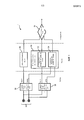
Фиг. 1 является блок-схемой системы 1, выполненной с возможностью диагностики апноэ во сне в соответствии с одним примерным вариантом осуществления принципа настоящего изобретения. Система 1 сконфигурирована с возможностью записи слышимых звуков, производимых пациентом, и, посредством записанных звуков, регистрации храпения пациента и движения головы пациента. Система 1 анализирует диаграммы храпения и движения головы пациента, чтобы оценить апноэ во сне пациента.FIG. 1 is a block diagram of a
Система 1 включает в себя решетку микрофонов 10. Решетка микрофонов 10 выполняет функцию записи слышимых звуков, производимых пациентом. В примерном варианте осуществления, показанном на фиг. 1, решетка микрофонов 10 включает в себя множественные микрофоны. Специалисту в данной области техники будет понятно, что любое число микрофонов больше одного можно применить без выхода за пределы объема принципа настоящего изобретения. Увеличение числа микрофонов в решетке микрофонов 10 позволяет сформировать более узкий пучок посредством решетки микрофонов 10.The
В некоторых примерных вариантах осуществления решетка микрофонов 10 расположена в виде линейной решетки микрофонов. В некоторых других примерных вариантах осуществления решетка микрофонов расположена в виде симметричной формы (например, без ограничения, треугольной, прямоугольной и т.п.). Симметричная форма может давать согласованную рабочую характеристику, когда ориентация решетки микрофонов 10 относительно пациента не известна заранее. В некоторых примерных вариантах осуществления микрофоны 10 в решетке расположены в пределах приблизительно 10 см друг от друга. Однако, принцип настоящего изобретения не ограничен вышеизложенным. Решетка микрофонов 10 может быть расположена любым подходящим образом, без выхода за пределы принципа настоящего изобретения.In some exemplary embodiments, the
Система 1 включает в себя также быстродействующий формирователь 20 пучка и медленнодействующий формирователь 30 пучка. Каждый из быстродействующего формирователя 20 пучка и медленнодействующего формирователя 30 пучка принимает и обрабатывает выходные сигналы каждого микрофона в решетке микрофонов 10. Быстродействующий формирователь 20 пучка и медленнодействующий формирователь 30 пучка обрабатывают выходные сигналы каждого микрофона в решетке микрофонов 10, чтобы формировать, каждый, направленный пучок с таким расчетом, чтобы звуки, принимаемые с направлений внутри пучка, усиливались, а звуки, принимаемые с направлений снаружи пучка, ослаблялись.
Быстродействующий формирователь 20 пучка и медленнодействующий формирователь 30 пучка фокусируют направления своих пучков на голове пациента и адаптируют направление своих пучков на основании движений головы пациента. Например и без ограничения, быстродействующий формирователь 20 пучка и медленнодействующий формирователь 30 пучка могут использовать храпение пациента для определения направления на голову пациента и отслеживания головы пациента. Однако, быстродействующий формирователь 20 пучка и медленнодействующий формирователь 30 пучка не адаптируются к направлению на голову пациента с одинаковым быстродействием. Напротив, быстродействующий формирователь 20 пучка имеет адаптационное быстродействие, которое быстрее, чем адаптационное быстродействие медленнодействующего формирователя 30 пучка. В примерном варианте осуществления быстродействующий формирователь 20 пучка имеет адаптационное быстродействие, которое является достаточно быстрым для отслеживания нормальных движений пациента (например, без ограничения, движения головы из-за храпения), тогда как медленнодействующий формирователь 30 пучка имеет адаптационное быстродействие, которое не является достаточно быстрым для отслеживания нормальных движений головы пациента, но является достаточно быстрым для отслеживания нормальных движений тела пациента (например, без ограничения, сдвига положения тела во время сна). По существу, в течение периодов движения головы пациента, которое обычно происходит в течение событий храпения, пучок быстродействующего формирователя 20 пучка остается сфокусированным на голове пациента, тогда как пучок медленнодействующего формирователя 30 пучка не точно фокусируется на голове пациента.The fast beam former 20 and the slow beam former 30 focus the directions of their beams on the patient’s head and adapt the direction of their beams based on the movements of the patient’s head. For example, and without limitation, the high-speed beam former 20 and the slow-action beam former 30 can use the patient's snoring to determine the direction of the patient’s head and track the patient’s head. However, the fast beam former 20 and the slow beam former 30 do not adapt to the direction of the patient’s head with the same speed. In contrast, the fast beam former 20 has adaptive speed that is faster than the adaptive speed of the slow beam former 30. In an exemplary embodiment, the high-speed beam former 20 has adaptive speed that is fast enough to track the normal movements of the patient (for example, without limitation, head movement due to snoring), while the slow-speed beam former 30 has adaptive speed that is not fast enough to track the normal movements of the patient’s head, but fast enough to track the normal movements of the patient’s body (for example, without ogre reduction, shift in body position during sleep). Essentially, during periods of movement of the patient’s head, which usually occurs during snoring events, the beam of the high-speed beam former 20 remains focused on the patient’s head, while the beam of the slow-action beam former 30 does not accurately focus on the patient’s head.
В дополнительном примерном варианте осуществления быстродействующий формирователь 20 пучка имеет адаптационное быстродействие короче, чем одна секунда, и медленнодействующий формирователь 30 пучка имеет адаптационное быстродействие дольше, чем десять секунд. Следует понимать, что адаптационное быстродействие короче, чем одна секунда является достаточно быстрым для отслеживания нормальной скорости движения головы, и адаптационное быстродействие дольше, чем десять секунд не является достаточно быстрым для отслеживания нормальных движений головы, но является достаточно быстрым для отслеживания нормального движения тела.In a further exemplary embodiment, the high-speed beam former 20 has an adaptive speed shorter than one second, and the slow-speed beam former 30 has an adaptive speed longer than ten seconds. It should be understood that adaptive performance is shorter than one second is fast enough to track the normal speed of head movement, and adaptive performance longer than ten seconds is not fast enough to track normal head movement, but is fast enough to track normal body movement.
Быстродействующий формирователь 20 пучка и медленнодействующий формирователь 30 пучка могут, каждый, представлять собой формирователь пучка любого подходящего типа. В примерном варианте осуществления, показанном на фиг. 1, быстродействующий формирователь 20 пучка и медленнодействующий формирователь 30 пучка относятся к типу преобразователей пучков с фильтрацией и суммированием. В других вариантах осуществления, быстродействующий формирователь 20 пучка и медленнодействующий формирователь 30 пучка могут быть реализованы по типу преобразователей пучков с вводом временных задержек и суммированием.The fast beam former 20 and the slow beam former 30 can each be any suitable beam former. In the exemplary embodiment shown in FIG. 1, a high-speed beam former 20 and a slow-beam beam former 30 are a type of beam converters with filtering and summing. In other embodiments, the fast beam former 20 and the slow beam former 30 can be implemented as beam converters with time delays and summing.
Быстродействующий формирователь 20 пучка и медленнодействующий формирователь 30 пучка выдают, каждый, уточненную аудиоинформацию и информацию шумов. Уточненная аудиоинформация является информацией о звуках, которые расположены внутри пучков быстродействующего формирователя 20 пучка и медленнодействующего формирователя 30 пучка. Информация шумов является информацией о звуках, которые расположены снаружи пучков быстродействующего формирователя 20 пучка и медленнодействующего формирователя 30 пучка.The fast beam former 20 and the slow beam former 30 give each updated audio information and noise information. The updated audio information is information about sounds that are located within the beams of the high-speed beam former 20 and the slow-beam beam former 30. The noise information is information about sounds that are located outside the beams of the high-speed beam former 20 and the slow-beam beam former 30.
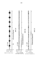
Фиг. 2A, 2B и 2C иллюстрируют примерные входные сигналы быстродействующего формирователя 20 пучка и медленнодействующего формирователя 30 пучка вместе с некоторыми выходными сигналами из быстродействующего формирователя 20 пучка и медленнодействующего формирователя 30 пучка. На фиг. 2A изображена примерная аудиоинформация, выдаваемая из решетки микрофонов 10 в течение периодов храпения и движения головы пациента. Как показано на фиг. 2A, событие 100 храпения вызывает повышение амплитуды сигнала.FIG. 2A, 2B, and 2C illustrate exemplary input signals of the high speed beam former 20 and the slow beam former 30 along with some output signals from the high speed beam former 20 and the slow beam former 30. In FIG. 2A depicts exemplary audio information outputted from the
На фиг. 2B показан примерный эталонный выходной шум быстродействующего формирователя 20 пучка. Как описано выше, информация шумов, выдаваемая из быстродействующего формирователя 20 пучка, включает в себя аудиоинформацию только с направлений, расположенных снаружи пучка. Поскольку пучок быстродействующего формирователя 20 пучка фокусируется на голове пациента, то событие 100' храпения в информации шумов не усиливается по амплитуде. Более того, как показано на фиг. 2B, информация шумов, выдаваемая из быстродействующего формирователя 20 пучка, включает в себя только внешний шум.In FIG. 2B shows an exemplary reference output noise of a high-speed beam former 20. As described above, noise information output from the high-speed beam former 20 includes audio information only from directions outside the beam. Since the beam of the high-speed beam former 20 focuses on the patient’s head, the snoring event 100 'in the noise information is not amplified in amplitude. Moreover, as shown in FIG. 2B, the noise information outputted from the high-speed beam former 20 includes only external noise.
На фиг. 2C показана примерная выходная информация шумов медленнодействующего формирователя 30 пучка. Как описано выше, медленнодействующий формирователь 30 пучка адаптируется не достаточно быстро для точного отслеживания движений головы пациента. По существу, в течение события 100" храпения какая-то часть аудио храпения будет оставаться в информации шумов, выдаваемой из медленнодействующего формирователя 30 пучка. Разность между информацией шумов из быстродействующего формирователя 20 пучка и медленнодействующего формирователя 30 пучка указывает, что движение головы пациента также присутствует в течение события 100 храпения.In FIG. 2C shows an example noise output of a slow beam former 30. As described above, the slow beam former 30 does not adapt quickly enough to accurately track patient head movements. Essentially, during the
В то время, как фиг. 2B и 2C поясняют примерную информацию шумов, выдаваемую из быстродействующего формирователя 20 пучка и медленнодействующего формирователя 30 пучка, быстродействующий формирователь 20 пучка и медленнодействующий формирователь 30 пучка выдает также уточненную аудиоинформацию. Как описано выше, уточненная аудиоинформация является аудиоинформацией с направлений внутри пучков быстродействующего формирователя 20 пучка и медленнодействующего формирователя 30 пучка. В течение периодов храпения и движения головы пациента, уточненная аудиоинформация, выдаваемая из быстродействующего формирователя 20 пучка и медленнодействующего формирователя 30 пучка, будет различаться, так как медленнодействующий формирователь 30 пучка не способен удерживать свой пучок сфокусированным на голове пациента в течение периодов движения головы.While FIG. 2B and 2C illustrate exemplary noise information provided from the high-speed beam former 20 and the slow-beam former 30, the high-speed beam former 20 and the slow beam former 30 also provide updated audio information. As described above, the refined audio information is audio information from directions within the beams of the high-speed beam former 20 and the slow-beam beam former 30. During periods of snoring and movement of the patient’s head, the updated audio information output from the high-speed beam former 20 and the slow-action beam former 30 will be different since the slow-acting beam former 30 is not able to keep its beam focused on the patient’s head during periods of head movement.
Как также показано на фиг. 1, выходные сигналы быстродействующего формирователя 20 пучка и медленнодействующего формирователя 30 пучка выдаются в блок 40 классификации аудио и блок 50 обнаружения движений головы, который включает в себя первый блок 52 обнаружения движений головы и второй блок 54 обнаружения движений головы. В примерном варианте осуществления, показанном на фиг. 1, уточненная аудиоинформация из быстродействующего формирователя 20 пучка выдается в блок 40 классификации аудио, и уточненная аудиоинформация из медленнодействующего формирователя 30 пучка выдается в первый блок 52 обнаружения движений головы. Информация шумов как из быстродействующего формирователя 20 пучка, так и из медленнодействующего формирователя 30 пучка выдается во второй блок 54 обнаружения движений головы.As also shown in FIG. 1, the output signals of the high-speed beam former 20 and the slow-beam beam former 30 are output to an
Блок 40 классификации аудио использует уточненную аудиоинформацию из быстродействующего формирователя 20 пучка для классификации акустических событий, например, и без ограничения, событий храпения. Другие акустические события, например, события кашля, чихания и стонов также могут классифицировать блоком 40 классификации аудио. Для классификации акустических событий, в блоке 40 классификации аудио можно применить известные методы классификации звуков. Например, и без ограничения, методы классификации звуков, описанные в опубликованной патентной заявке США № 2011/0087079, можно соответственно модифицировать для применения в блоке 40 классификации аудио. Так как уточненная аудиоинформация из быстродействующего формирователя 20 пучка включает в себя звуки только с направлений внутри его пучка, то уточненная аудиоинформация из быстродействующего формирователя 20 пучка является относительно свободным от шума аудио храпения пациента, и поэтому уточненная аудиоинформация из быстродействующего формирователя 20 пучка достаточно подходит для использования при классификации событий храпения. Блок 40 классификации аудио выдает информацию о классифицированных акустических событиях.The
Система 1 включает в себя также блок 50 обнаружения движений головы, включающий в себя первый блок 52 обнаружения движений головы и второй блок 54 обнаружения движений головы. Блок 50 обнаружения движений головы обнаруживает движение головы пациента на основании уточненной аудиоинформации быстродействующего формирователя 20 пучка и информации шумов из быстродействующего формирователя 20 пучка и медленнодействующего формирователя 30 пучка.
Первый блок 52 обнаружения движений головы принимает уточненную аудиоинформацию из медленнодействующего формирователя 30 пучка. Как описано выше, медленнодействующий формирователь 30 пучка адаптируется не достаточно быстро для отслеживания движения головы пациента. По существу, в течение периодов храпения и движения головы, уточненная аудиоинформация из медленнодействующего формирователя 30 пучка будет изменяться из-за того, что его пучок не фокусируется прямо на голове пациента. Первый блок 52 обнаружения движений головы анализирует уточненную аудиоинформацию из медленнодействующего формирователя 30 пучка для учета упомянутых изменений и таким образом определяет, когда происходит перемещение головы. В некоторых примерных вариантах осуществления, первый блок 52 обнаружения движений головы включает в себя блок анализа огибающей, который выполняет анализ огибающей в уточненной аудиоинформации из медленнодействующего формирователя 30 пучка, чтобы определять, когда происходит перемещение головы. Первый блок 52 обнаружения движений головы выдает первую информацию о движениях головы.The first head
Система 1 дополнительно включает в себя второй блок 54 обнаружения движений головы. Второй блок 54 обнаружения движений головы принимает информацию шумов как из быстродействующего формирователя 20 пучка, так и из медленнодействующего формирователя 30 пучка. Как описано выше со ссылкой на фиг. 2B и 2C, различие между информацией шумов из быстродействующего формирователя 20 пучка и медленнодействующего формирователя 30 пучка может указывать на период движения головы. Второй блок 54 обнаружения движений головы анализирует информацию шумов из быстродействующего формирователя 20 пучка и медленнодействующего формирователя 30 пучка, чтобы определять, когда происходит перемещение головы. Второй блок 54 обнаружения движений головы может включать в себя, например, и без ограничения, блок анализа с помощью фильтров. Второй блок 54 обнаружения движений головы выдает вторую информацию о движениях головы.
Система 1 дополнительно включает в себя диагностический блок 70. Диагностический блок 70 принимает выходные сигналы блока 40 классификации аудио и блока 50 обнаружения движений головы. То есть, диагностический блок 70 принимает информацию о классификации аудио из блока 40 классификации аудио, первую информацию о движениях головы из первого блока 52 обнаружения движений головы и вторую информацию о движениях головы из второго блока 54 обнаружения движений головы. На основании принятой информации, диагностический блок 70 может анализировать диаграммы храпения и движений головы пациента.
Одна лишь информация о храпении не может точно указывать на состояние апноэ во сне. Аналогично, одна лишь информация о движениях головы также не может точно указывать на состояние апноэ во сне. При использовании как информации о храпении, так и информации о движениях головы, диагностический блок 70 может точнее диагностировать состояние апноэ во сне. Диагностический блок 70 выдает информацию о диагностированном состоянии апноэ во сне, которую можно впоследствии использовать, например, для назначения программы лечения для пациента.Information on snoring alone cannot accurately indicate sleep apnea. Similarly, information about head movements alone cannot accurately indicate sleep apnea. Using both snoring information and head movement information, the
Кроме того, система 1 может диагностировать состояние апноэ во сне только по аудио пациента. По существу, система 1 является менее навязчивой, чем другие системы диагностики апноэ во сне, которые используют датчики, например, акселерометры, для контроля перемещения головы пациента. Кроме того, поскольку система 1 использует как информацию о храпении, так и информацию о движениях головы, система 1 может обеспечивать более точный диагноз, чем другие системы диагностики апноэ во сне, которые используют только информацию о событии храпения или только информацию о движениях головы.In addition,
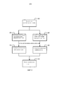
На фиг. 3 показана блок-схема последовательности операций способа формирования информации о классификации аудио и движениях головы в соответствии с одним примерным вариантом осуществления. Информацию о классификации аудио и движениях головы можно впоследствии использовать для диагностики апноэ во сне. Способ начинается на этапе 100, на котором регистрируют звуки, производимые пациентом, и формируется аудиоинформация о пациенте. Регистрация звуков, производимых пациентом, и формирование аудиоинформации о пациенте могут выполняться решеткой микрофонов. Затем аудиоинформация о пациенте обрабатывается быстродействующим формирователем пучка на этапе 102 и медленнодействующим формирователем пучка на этапе 104. Быстродействующий формирователь пучка имеет адаптационное быстродействие, которое является достаточно быстрым для отслеживания нормальных движений головы пациента, и медленнодействующий формирователь пучка имеет адаптационное быстродействие, которое является слишком медленным для отслеживания нормальных движений головы пациента, но является достаточно быстрым для отслеживания нормальных движений тела пациента. Быстродействующий формирователь пучка и медленнодействующий формирователь пучка выдают, каждый, уточненную аудиоинформацию и информацию шумов, как описано выше со ссылкой на фиг. 1.In FIG. 3 is a flowchart of a method for generating audio classification information and head movements in accordance with one exemplary embodiment. Information on the classification of audio and head movements can subsequently be used to diagnose sleep apnea. The method begins at
На этапе 106 формируется информация о классификации аудио. Информация о классификации аудио формируется на основании уточненной аудиоинформации из быстродействующего формирователя пучка. На этапе 108 формируется информация о движениях головы. Информация о движениях головы может включать в себя первую информацию о движениях головы, сформированную на основании уточненной аудиоинформации из второго формирователя пучка, и вторую информацию о движениях головы, основанную на информации шумов из быстродействующего формирователя пучка и медленнодействующего формирователя пучка. Как отмечено выше, информация о классификации аудио и информация о движениях головы можно впоследствии использовать для диагностики апноэ во сне, как показано на этапе 110.At
Принцип настоящего изобретения может быть осуществлен в электронном устройстве, например, и без ограничения, мобильном устройстве, мобильном компьютере, планшетном компьютере, периферийном устройстве и т.п. Принцип настоящего изобретения может быть также осуществлен в виде машиночитаемых кодов на машиночитаемом носителе записи. Машиночитаемый носитель записи является любым устройством для хранения данных, которое может хранить данные, которые могут впоследствии считываться компьютерной системой. Примеры машиночитаемых носителей записи включают в себя постоянную память (ROM), оперативную память (RAM), постоянную память на компакт-диске (CD-ROM), магнитные ленты, гибкие диски и оптические устройства для хранения данных.The principle of the present invention can be implemented in an electronic device, for example, and without limitation, a mobile device, mobile computer, tablet computer, peripheral device, etc. The principle of the present invention can also be implemented in the form of computer-readable codes on a computer-readable recording medium. A computer-readable recording medium is any data storage device that can store data that can subsequently be read by a computer system. Examples of computer-readable storage media include read-only memory (ROM), random access memory (RAM), read-only memory on a compact disc (CD-ROM), magnetic tapes, floppy disks, and optical storage devices.
В формуле изобретения, никакие позиции, заключенные в скобки, нельзя рассматривать как ограничивающие пункт формулы изобретения. Формулировка «содержащий» или «включающий в себя» не исключает присутствия других элементов или этапов, кроме тех, которые перечислены в пункте формулы изобретения. В пункте формулы изобретения на устройство, перечисляющем несколько средств, некоторые из данных средств могут быть осуществлены одним и тем же элементом аппаратуры. Признак единственного числа, используемого в отношении элементов, не исключает присутствия множества таких элементов. В любом пункте формулы изобретения на устройство, перечисляющем несколько средств, некоторые из данных средств могут быть осуществлены одним и тем же элементом аппаратуры. Очевидное обстоятельство, что некоторые элементы упомянуты во взаимно различающихся зависимых пунктах формулы изобретения, не означает, что упомянутые элементы нельзя применять в комбинации.In the claims, no positions in parentheses should be construed as limiting the claims. The wording “comprising” or “including” does not exclude the presence of other elements or steps other than those listed in a claim. In a claim on a device listing several means, some of these means may be implemented by the same piece of equipment. The singular used in relation to elements does not exclude the presence of a plurality of such elements. At any point in the claims on a device listing several means, some of these means may be implemented by the same piece of equipment. The obvious fact that some elements are mentioned in mutually different dependent dependent claims does not mean that these elements cannot be used in combination.
Хотя изобретение подробно описано выше с целью иллюстрации на основании того, что в настоящее время считают наиболее полезными и предпочтительными вариантами осуществления, следует понимать, что приведенное подробное описание предназначено только для данной цели, и что изобретение не ограничено раскрытыми вариантами осуществления, но, напротив, предназначено для охвата модификаций и эквивалентных конфигураций, которые находятся в пределах существа и объема охраны прилагаемой формулы изобретения. Например, следует понимать, что настоящее изобретение предусматривает, что, насколько возможно, один или более признаков любого варианта осуществления можно объединять с одним или более признаками любого другого варианта осуществления.Although the invention has been described in detail above for the purpose of illustration on the basis of what is currently considered the most useful and preferred embodiments, it should be understood that the above detailed description is intended for this purpose only and that the invention is not limited to the disclosed embodiments, but, on the contrary, Designed to cover modifications and equivalent configurations that fall within the spirit and scope of the appended claims. For example, it should be understood that the present invention provides that, as far as possible, one or more features of any embodiment can be combined with one or more features of any other embodiment.
Claims (26)
Applications Claiming Priority (3)
| Application Number | Priority Date | Filing Date | Title |
|---|---|---|---|
| US201261738026P | 2012-12-17 | 2012-12-17 | |
| US61/738,026 | 2012-12-17 | ||
| PCT/IB2013/060983 WO2014097114A1 (en) | 2012-12-17 | 2013-12-16 | Sleep apnea diagnosis system and method of generating information using non-obtrusive audio analysis |
Publications (2)
| Publication Number | Publication Date |
|---|---|
| RU2015129091A RU2015129091A (en) | 2017-01-23 |
| RU2667724C2 true RU2667724C2 (en) | 2018-09-24 |
Family
ID=50114409
Family Applications (1)
| Application Number | Title | Priority Date | Filing Date |
|---|---|---|---|
| RU2015129091A RU2667724C2 (en) | 2012-12-17 | 2013-12-16 | Sleep apnea diagnostic system and method for forming information with use of nonintrusive analysis of audio signals |
Country Status (7)
| Country | Link |
|---|---|
| US (1) | US9833189B2 (en) |
| EP (1) | EP2931118B1 (en) |
| JP (1) | JP6266648B2 (en) |
| CN (1) | CN104853671B (en) |
| BR (1) | BR112015013907A2 (en) |
| RU (1) | RU2667724C2 (en) |
| WO (1) | WO2014097114A1 (en) |
Families Citing this family (9)
| Publication number | Priority date | Publication date | Assignee | Title |
|---|---|---|---|---|
| CN106294331B (en) | 2015-05-11 | 2020-01-21 | 阿里巴巴集团控股有限公司 | Audio information retrieval method and device |
| JP6644959B1 (en) * | 2017-01-03 | 2020-02-12 | コーニンクレッカ フィリップス エヌ ヴェKoninklijke Philips N.V. | Audio capture using beamforming |
| RU2645410C1 (en) * | 2017-04-27 | 2018-02-21 | Федеральное государственное бюджетное научное учреждение "Научный центр неврологии" (ФГБНУ НЦН) | Method for improving early functional neurologic recovery in patients with ischemic stroke and respiratory depression in sleep |
| US11749298B2 (en) * | 2018-05-08 | 2023-09-05 | Cirrus Logic Inc. | Health-related information generation and storage |
| CN110013222A (en) * | 2019-04-03 | 2019-07-16 | 杭州电子科技大学 | A kind of system for sleep apnea detection |
| CN110301890B (en) * | 2019-05-31 | 2021-09-07 | 华为技术有限公司 | Apnea monitoring method and device |
| EP3838137A1 (en) * | 2019-12-19 | 2021-06-23 | Koninklijke Philips N.V. | Automated and objective symptom severity score |
| CN111904424B (en) * | 2020-08-06 | 2021-08-24 | 苏州国科医工科技发展(集团)有限公司 | Sleep monitoring and regulating system based on phased array microphone |
| US11881219B2 (en) | 2020-09-28 | 2024-01-23 | Hill-Rom Services, Inc. | Voice control in a healthcare facility |
Citations (8)
| Publication number | Priority date | Publication date | Assignee | Title |
|---|---|---|---|---|
| RU2185710C2 (en) * | 1997-08-20 | 2002-07-20 | Фонак Аг | Method and acoustic transducer for electronic generation of directivity pattern for acoustic signals |
| WO2009034524A1 (en) * | 2007-09-13 | 2009-03-19 | Koninklijke Philips Electronics N.V. | Apparatus and method for audio beam forming |
| RU2369042C2 (en) * | 2004-03-02 | 2009-09-27 | Майкрософт Корпорейшн | System and method for beam formation using microphone grid |
| EP2238910A1 (en) * | 2009-04-08 | 2010-10-13 | Alcatel Lucent | Monitoring device |
| US7835529B2 (en) * | 2003-03-19 | 2010-11-16 | Irobot Corporation | Sound canceling systems and methods |
| US20110087079A1 (en) * | 2008-06-17 | 2011-04-14 | Koninklijke Philips Electronics N.V. | Acoustical patient monitoring using a sound classifier and a microphone |
| WO2011141916A1 (en) * | 2010-05-13 | 2011-11-17 | Sensewiser Ltd. | Contactless non-invasive analyzer of breathing sounds |
| RU2456701C2 (en) * | 2008-03-18 | 2012-07-20 | Квэлкомм Инкорпорейтед | Higher speech intelligibility with application of several microphones on several devices |
Family Cites Families (16)
| Publication number | Priority date | Publication date | Assignee | Title |
|---|---|---|---|---|
| US4802485A (en) | 1987-09-02 | 1989-02-07 | Sentel Technologies, Inc. | Sleep apnea monitor |
| US5797852A (en) | 1993-02-04 | 1998-08-25 | Local Silence, Inc. | Sleep apnea screening and/or detecting apparatus and method |
| US6241683B1 (en) * | 1998-02-20 | 2001-06-05 | INSTITUT DE RECHERCHES CLINIQUES DE MONTRéAL (IRCM) | Phonospirometry for non-invasive monitoring of respiration |
| AU2002246880B2 (en) | 2000-12-29 | 2006-12-07 | Watermark Medical, Inc. | Sleep apnea risk evaluation |
| EP1410759A1 (en) | 2002-10-17 | 2004-04-21 | Sibel, S.A. | Procedure for analysis of snoring and apnea and apparatus to carry out this analysis |
| JP4407365B2 (en) * | 2004-04-23 | 2010-02-03 | パナソニック電工株式会社 | Sleep state detection device |
| FI120716B (en) * | 2005-12-20 | 2010-02-15 | Smart Valley Software Oy | A method for measuring and analyzing the movements of a human or animal using audio signals |
| US7559903B2 (en) | 2007-03-28 | 2009-07-14 | Tr Technologies Inc. | Breathing sound analysis for detection of sleep apnea/popnea events |
| US8175291B2 (en) * | 2007-12-19 | 2012-05-08 | Qualcomm Incorporated | Systems, methods, and apparatus for multi-microphone based speech enhancement |
| EP2146519B1 (en) * | 2008-07-16 | 2012-06-06 | Nuance Communications, Inc. | Beamforming pre-processing for speaker localization |
| WO2010044162A1 (en) * | 2008-10-16 | 2010-04-22 | 富士通株式会社 | Apnea detection program, apnea detector, and apnea detection method |
| WO2011015979A2 (en) | 2009-08-07 | 2011-02-10 | Koninklijke Philips Electronics N.V. | Active sound reduction system and method |
| CA2800885A1 (en) | 2010-05-28 | 2011-12-01 | Mayo Foundation For Medical Education And Research | Sleep apnea detection system |
| US20130310657A1 (en) * | 2010-09-24 | 2013-11-21 | Sonomedical Pty Ltd | Electronic Monitoring System for Data Collection, Presentation and Analysis |
| US9100734B2 (en) * | 2010-10-22 | 2015-08-04 | Qualcomm Incorporated | Systems, methods, apparatus, and computer-readable media for far-field multi-source tracking and separation |
| EP2663230B1 (en) * | 2011-01-12 | 2015-03-18 | Koninklijke Philips N.V. | Improved detection of breathing in the bedroom |
-
2013
- 2013-12-16 RU RU2015129091A patent/RU2667724C2/en active
- 2013-12-16 JP JP2015547254A patent/JP6266648B2/en active Active
- 2013-12-16 BR BR112015013907A patent/BR112015013907A2/en not_active Application Discontinuation
- 2013-12-16 US US14/647,475 patent/US9833189B2/en active Active
- 2013-12-16 CN CN201380065762.3A patent/CN104853671B/en active Active
- 2013-12-16 WO PCT/IB2013/060983 patent/WO2014097114A1/en active Application Filing
- 2013-12-16 EP EP13830098.3A patent/EP2931118B1/en active Active
Patent Citations (8)
| Publication number | Priority date | Publication date | Assignee | Title |
|---|---|---|---|---|
| RU2185710C2 (en) * | 1997-08-20 | 2002-07-20 | Фонак Аг | Method and acoustic transducer for electronic generation of directivity pattern for acoustic signals |
| US7835529B2 (en) * | 2003-03-19 | 2010-11-16 | Irobot Corporation | Sound canceling systems and methods |
| RU2369042C2 (en) * | 2004-03-02 | 2009-09-27 | Майкрософт Корпорейшн | System and method for beam formation using microphone grid |
| WO2009034524A1 (en) * | 2007-09-13 | 2009-03-19 | Koninklijke Philips Electronics N.V. | Apparatus and method for audio beam forming |
| RU2456701C2 (en) * | 2008-03-18 | 2012-07-20 | Квэлкомм Инкорпорейтед | Higher speech intelligibility with application of several microphones on several devices |
| US20110087079A1 (en) * | 2008-06-17 | 2011-04-14 | Koninklijke Philips Electronics N.V. | Acoustical patient monitoring using a sound classifier and a microphone |
| EP2238910A1 (en) * | 2009-04-08 | 2010-10-13 | Alcatel Lucent | Monitoring device |
| WO2011141916A1 (en) * | 2010-05-13 | 2011-11-17 | Sensewiser Ltd. | Contactless non-invasive analyzer of breathing sounds |
Also Published As
| Publication number | Publication date |
|---|---|
| JP2016504087A (en) | 2016-02-12 |
| EP2931118A1 (en) | 2015-10-21 |
| US20150297131A1 (en) | 2015-10-22 |
| CN104853671B (en) | 2019-04-30 |
| US9833189B2 (en) | 2017-12-05 |
| RU2015129091A (en) | 2017-01-23 |
| EP2931118B1 (en) | 2021-09-01 |
| CN104853671A (en) | 2015-08-19 |
| WO2014097114A1 (en) | 2014-06-26 |
| JP6266648B2 (en) | 2018-01-24 |
| BR112015013907A2 (en) | 2017-07-11 |
Similar Documents
| Publication | Publication Date | Title |
|---|---|---|
| RU2667724C2 (en) | Sleep apnea diagnostic system and method for forming information with use of nonintrusive analysis of audio signals | |
| US11534100B2 (en) | On-ear detection | |
| Kalkbrenner et al. | Apnea and heart rate detection from tracheal body sounds for the diagnosis of sleep-related breathing disorders | |
| JP2019521756A (en) | Method for detecting occlusion in a fluid flow vessel | |
| JP2010524564A (en) | Heart sound tracking system and heart sound tracking method | |
| JP2013518607A (en) | Method and system for classifying physiological signal quality for portable monitoring | |
| CN110301890B (en) | Apnea monitoring method and device | |
| Hillman et al. | Ambulatory monitoring of daily voice use | |
| US20090192401A1 (en) | Method and system for heart sound identification | |
| JP2014087543A (en) | Cardiac sound information processing device, cardiac sound information processing method, and cardiac sound information processing program | |
| Młyńczak et al. | Joint apnea and body position analysis for home sleep studies using a wireless audio and motion sensor | |
| Griffel et al. | Detection of coronary artery disease using automutual information | |
| JP2004529716A (en) | Electronic monitoring device | |
| US7988629B2 (en) | Cerebrum evaluation device | |
| Gonzalez-Landaeta et al. | Estimation of systolic blood pressure by Random Forest using heart sounds and a ballistocardiogram | |
| Dafna et al. | Automatic detection of snoring events using Gaussian mixture models | |
| KR20180111716A (en) | Implantable hearing aid device and mastication noise reduction device of fully implantable hearing aid | |
| JP7320867B2 (en) | Medical devices and programs | |
| Grundlehner et al. | Methods to characterize sensors for capturing body sounds | |
| US20230240560A1 (en) | Hearing Device-Based Systems and Methods for Determining a Heart Rate Value | |
| Zhang et al. | EarCough: Enabling Continuous Subject Cough Event Detection on Hearables | |
| JP2007323171A (en) | Content reproduction system | |
| JP6942288B2 (en) | Information processing equipment, sound masking system, control method, and control program | |
| Lukkarinen | Phonocardiography: Development of a clinical system and its application to screening for paediatric heart murmurs | |
| KR101933966B1 (en) | Implantable hearing aid device and mastication noise reduction device of fully implantable hearing aid |