RU2658671C2 - Bistatic radar station - Google Patents
Bistatic radar station Download PDFInfo
- Publication number
- RU2658671C2 RU2658671C2 RU2016122083A RU2016122083A RU2658671C2 RU 2658671 C2 RU2658671 C2 RU 2658671C2 RU 2016122083 A RU2016122083 A RU 2016122083A RU 2016122083 A RU2016122083 A RU 2016122083A RU 2658671 C2 RU2658671 C2 RU 2658671C2
- Authority
- RU
- Russia
- Prior art keywords
- antenna
- bistatic radar
- radar
- truncated cone
- transmitting
- Prior art date
Links
Images


Classifications
-
- G—PHYSICS
- G01—MEASURING; TESTING
- G01S—RADIO DIRECTION-FINDING; RADIO NAVIGATION; DETERMINING DISTANCE OR VELOCITY BY USE OF RADIO WAVES; LOCATING OR PRESENCE-DETECTING BY USE OF THE REFLECTION OR RERADIATION OF RADIO WAVES; ANALOGOUS ARRANGEMENTS USING OTHER WAVES
- G01S13/00—Systems using the reflection or reradiation of radio waves, e.g. radar systems; Analogous systems using reflection or reradiation of waves whose nature or wavelength is irrelevant or unspecified
- G01S13/02—Systems using reflection of radio waves, e.g. primary radar systems; Analogous systems
- G01S13/06—Systems determining position data of a target
- G01S13/42—Simultaneous measurement of distance and other co-ordinates
-
- G—PHYSICS
- G01—MEASURING; TESTING
- G01S—RADIO DIRECTION-FINDING; RADIO NAVIGATION; DETERMINING DISTANCE OR VELOCITY BY USE OF RADIO WAVES; LOCATING OR PRESENCE-DETECTING BY USE OF THE REFLECTION OR RERADIATION OF RADIO WAVES; ANALOGOUS ARRANGEMENTS USING OTHER WAVES
- G01S13/00—Systems using the reflection or reradiation of radio waves, e.g. radar systems; Analogous systems using reflection or reradiation of waves whose nature or wavelength is irrelevant or unspecified
- G01S13/003—Bistatic radar systems; Multistatic radar systems
-
- G—PHYSICS
- G01—MEASURING; TESTING
- G01S—RADIO DIRECTION-FINDING; RADIO NAVIGATION; DETERMINING DISTANCE OR VELOCITY BY USE OF RADIO WAVES; LOCATING OR PRESENCE-DETECTING BY USE OF THE REFLECTION OR RERADIATION OF RADIO WAVES; ANALOGOUS ARRANGEMENTS USING OTHER WAVES
- G01S13/00—Systems using the reflection or reradiation of radio waves, e.g. radar systems; Analogous systems using reflection or reradiation of waves whose nature or wavelength is irrelevant or unspecified
- G01S13/02—Systems using reflection of radio waves, e.g. primary radar systems; Analogous systems
- G01S13/06—Systems determining position data of a target
- G01S13/42—Simultaneous measurement of distance and other co-ordinates
- G01S13/426—Scanning radar, e.g. 3D radar
-
- G—PHYSICS
- G01—MEASURING; TESTING
- G01S—RADIO DIRECTION-FINDING; RADIO NAVIGATION; DETERMINING DISTANCE OR VELOCITY BY USE OF RADIO WAVES; LOCATING OR PRESENCE-DETECTING BY USE OF THE REFLECTION OR RERADIATION OF RADIO WAVES; ANALOGOUS ARRANGEMENTS USING OTHER WAVES
- G01S13/00—Systems using the reflection or reradiation of radio waves, e.g. radar systems; Analogous systems using reflection or reradiation of waves whose nature or wavelength is irrelevant or unspecified
- G01S13/02—Systems using reflection of radio waves, e.g. primary radar systems; Analogous systems
- G01S13/06—Systems determining position data of a target
- G01S13/42—Simultaneous measurement of distance and other co-ordinates
- G01S13/44—Monopulse radar, i.e. simultaneous lobing
- G01S13/4463—Monopulse radar, i.e. simultaneous lobing using phased arrays
-
- G—PHYSICS
- G01—MEASURING; TESTING
- G01S—RADIO DIRECTION-FINDING; RADIO NAVIGATION; DETERMINING DISTANCE OR VELOCITY BY USE OF RADIO WAVES; LOCATING OR PRESENCE-DETECTING BY USE OF THE REFLECTION OR RERADIATION OF RADIO WAVES; ANALOGOUS ARRANGEMENTS USING OTHER WAVES
- G01S13/00—Systems using the reflection or reradiation of radio waves, e.g. radar systems; Analogous systems using reflection or reradiation of waves whose nature or wavelength is irrelevant or unspecified
- G01S13/02—Systems using reflection of radio waves, e.g. primary radar systems; Analogous systems
- G01S13/06—Systems determining position data of a target
- G01S13/46—Indirect determination of position data
- G01S13/48—Indirect determination of position data using multiple beams at emission or reception
-
- G—PHYSICS
- G01—MEASURING; TESTING
- G01S—RADIO DIRECTION-FINDING; RADIO NAVIGATION; DETERMINING DISTANCE OR VELOCITY BY USE OF RADIO WAVES; LOCATING OR PRESENCE-DETECTING BY USE OF THE REFLECTION OR RERADIATION OF RADIO WAVES; ANALOGOUS ARRANGEMENTS USING OTHER WAVES
- G01S13/00—Systems using the reflection or reradiation of radio waves, e.g. radar systems; Analogous systems using reflection or reradiation of waves whose nature or wavelength is irrelevant or unspecified
- G01S13/66—Radar-tracking systems; Analogous systems
- G01S13/72—Radar-tracking systems; Analogous systems for two-dimensional tracking, e.g. combination of angle and range tracking, track-while-scan radar
-
- G—PHYSICS
- G01—MEASURING; TESTING
- G01S—RADIO DIRECTION-FINDING; RADIO NAVIGATION; DETERMINING DISTANCE OR VELOCITY BY USE OF RADIO WAVES; LOCATING OR PRESENCE-DETECTING BY USE OF THE REFLECTION OR RERADIATION OF RADIO WAVES; ANALOGOUS ARRANGEMENTS USING OTHER WAVES
- G01S13/00—Systems using the reflection or reradiation of radio waves, e.g. radar systems; Analogous systems using reflection or reradiation of waves whose nature or wavelength is irrelevant or unspecified
- G01S13/87—Combinations of radar systems, e.g. primary radar and secondary radar
-
- G—PHYSICS
- G01—MEASURING; TESTING
- G01S—RADIO DIRECTION-FINDING; RADIO NAVIGATION; DETERMINING DISTANCE OR VELOCITY BY USE OF RADIO WAVES; LOCATING OR PRESENCE-DETECTING BY USE OF THE REFLECTION OR RERADIATION OF RADIO WAVES; ANALOGOUS ARRANGEMENTS USING OTHER WAVES
- G01S3/00—Direction-finders for determining the direction from which infrasonic, sonic, ultrasonic, or electromagnetic waves, or particle emission, not having a directional significance, are being received
- G01S3/02—Direction-finders for determining the direction from which infrasonic, sonic, ultrasonic, or electromagnetic waves, or particle emission, not having a directional significance, are being received using radio waves
- G01S3/72—Diversity systems specially adapted for direction-finding
-
- G—PHYSICS
- G01—MEASURING; TESTING
- G01S—RADIO DIRECTION-FINDING; RADIO NAVIGATION; DETERMINING DISTANCE OR VELOCITY BY USE OF RADIO WAVES; LOCATING OR PRESENCE-DETECTING BY USE OF THE REFLECTION OR RERADIATION OF RADIO WAVES; ANALOGOUS ARRANGEMENTS USING OTHER WAVES
- G01S7/00—Details of systems according to groups G01S13/00, G01S15/00, G01S17/00
- G01S7/02—Details of systems according to groups G01S13/00, G01S15/00, G01S17/00 of systems according to group G01S13/00
- G01S7/41—Details of systems according to groups G01S13/00, G01S15/00, G01S17/00 of systems according to group G01S13/00 using analysis of echo signal for target characterisation; Target signature; Target cross-section
-
- H—ELECTRICITY
- H01—ELECTRIC ELEMENTS
- H01Q—ANTENNAS, i.e. RADIO AERIALS
- H01Q1/00—Details of, or arrangements associated with, antennas
- H01Q1/27—Adaptation for use in or on movable bodies
- H01Q1/32—Adaptation for use in or on road or rail vehicles
- H01Q1/3208—Adaptation for use in or on road or rail vehicles characterised by the application wherein the antenna is used
- H01Q1/3216—Adaptation for use in or on road or rail vehicles characterised by the application wherein the antenna is used where the road or rail vehicle is only used as transportation means
-
- H—ELECTRICITY
- H01—ELECTRIC ELEMENTS
- H01Q—ANTENNAS, i.e. RADIO AERIALS
- H01Q1/00—Details of, or arrangements associated with, antennas
- H01Q1/27—Adaptation for use in or on movable bodies
- H01Q1/32—Adaptation for use in or on road or rail vehicles
- H01Q1/3208—Adaptation for use in or on road or rail vehicles characterised by the application wherein the antenna is used
- H01Q1/3233—Adaptation for use in or on road or rail vehicles characterised by the application wherein the antenna is used particular used as part of a sensor or in a security system, e.g. for automotive radar, navigation systems
-
- H—ELECTRICITY
- H01—ELECTRIC ELEMENTS
- H01Q—ANTENNAS, i.e. RADIO AERIALS
- H01Q1/00—Details of, or arrangements associated with, antennas
- H01Q1/27—Adaptation for use in or on movable bodies
- H01Q1/34—Adaptation for use in or on ships, submarines, buoys or torpedoes
-
- H—ELECTRICITY
- H01—ELECTRIC ELEMENTS
- H01Q—ANTENNAS, i.e. RADIO AERIALS
- H01Q21/00—Antenna arrays or systems
- H01Q21/06—Arrays of individually energised antenna units similarly polarised and spaced apart
- H01Q21/20—Arrays of individually energised antenna units similarly polarised and spaced apart the units being spaced along or adjacent to a curvilinear path
- H01Q21/205—Arrays of individually energised antenna units similarly polarised and spaced apart the units being spaced along or adjacent to a curvilinear path providing an omnidirectional coverage
-
- H—ELECTRICITY
- H01—ELECTRIC ELEMENTS
- H01Q—ANTENNAS, i.e. RADIO AERIALS
- H01Q3/00—Arrangements for changing or varying the orientation or the shape of the directional pattern of the waves radiated from an antenna or antenna system
- H01Q3/24—Arrangements for changing or varying the orientation or the shape of the directional pattern of the waves radiated from an antenna or antenna system varying the orientation by switching energy from one active radiating element to another, e.g. for beam switching
- H01Q3/242—Circumferential scanning
-
- H—ELECTRICITY
- H01—ELECTRIC ELEMENTS
- H01Q—ANTENNAS, i.e. RADIO AERIALS
- H01Q3/00—Arrangements for changing or varying the orientation or the shape of the directional pattern of the waves radiated from an antenna or antenna system
- H01Q3/26—Arrangements for changing or varying the orientation or the shape of the directional pattern of the waves radiated from an antenna or antenna system varying the relative phase or relative amplitude of energisation between two or more active radiating elements; varying the distribution of energy across a radiating aperture
-
- G—PHYSICS
- G01—MEASURING; TESTING
- G01S—RADIO DIRECTION-FINDING; RADIO NAVIGATION; DETERMINING DISTANCE OR VELOCITY BY USE OF RADIO WAVES; LOCATING OR PRESENCE-DETECTING BY USE OF THE REFLECTION OR RERADIATION OF RADIO WAVES; ANALOGOUS ARRANGEMENTS USING OTHER WAVES
- G01S13/00—Systems using the reflection or reradiation of radio waves, e.g. radar systems; Analogous systems using reflection or reradiation of waves whose nature or wavelength is irrelevant or unspecified
- G01S13/02—Systems using reflection of radio waves, e.g. primary radar systems; Analogous systems
- G01S2013/0236—Special technical features
- G01S2013/0245—Radar with phased array antenna
- G01S2013/0254—Active array antenna
Landscapes
- Engineering & Computer Science (AREA)
- Radar, Positioning & Navigation (AREA)
- Remote Sensing (AREA)
- Physics & Mathematics (AREA)
- General Physics & Mathematics (AREA)
- Computer Networks & Wireless Communication (AREA)
- Computer Security & Cryptography (AREA)
- Variable-Direction Aerials And Aerial Arrays (AREA)
- Radar Systems Or Details Thereof (AREA)
Abstract
Description
[001] Настоящее описание относится к технической области применения радиолокационных систем, в частности, к бистатической радиолокационной станции (РЛС).[001] The present description relates to the technical field of application of radar systems, in particular to a bistatic radar station.
[002] Известно, что сухопутные транспортные средства или суда, например, военные корабли, оснащаются радиолокационными системами, позволяющими контролировать окружающее пространство для выявления возможных угроз.[002] It is known that land vehicles or ships, such as warships, are equipped with radar systems that allow you to control the surrounding area to identify possible threats.
[003] Данные радиолокационные системы с течением времени прошли длительную эволюцию. Вначале радиолокационные системы разрабатывались с углом обзора луча 360° в азимутальной плоскости, при этом РЛС содержала объемную отражательную антенну, обычно устанавливаемую на вращающейся платформе, смонтированной на транспортном средстве. Вышеуказанные радиолокационные системы со временем эволюционировали в самые современные радиолокационные системы, у которых не было вращающихся платформ и в которых для обеспечения как можно более широкого обзора в азимутальной плоскости используется несколько активных плоских фазированных антенных решеток (ФАР). Например, известны радиолокационные системы, у которых имеется четыре активных плоских ФАР, каждая из которых установлена на передней части корабельной мачты и по существу имеет форму усеченной пирамиды с четырехугольным основанием.[003] These radar systems have evolved over time. Initially, radar systems were developed with a beam angle of 360 ° in the azimuthal plane, while the radar contained a three-dimensional reflective antenna, usually mounted on a rotating platform mounted on a vehicle. The above radar systems have evolved over time into the most advanced radar systems, which did not have rotating platforms and in which several active phased active antenna arrays (PAR) are used to provide the widest possible overview in the azimuthal plane. For example, radar systems are known in which there are four active flat headlights, each of which is mounted on the front of the ship's mast and essentially has the shape of a truncated pyramid with a quadrangular base.
[004] Активная РЛС с ФАР, благодаря способности быстро и контролируемо менять направление луча, дает возможность носителю, например, военному кораблю, использовать единственную радиолокационную систему для обнаружения объектов и контроля поверхностей (например, для выявления кораблей), контроля воздушного пространства (для обнаружения воздушных судов и ракет), направления управляемых ракет и управления артиллерийскими системами.[004] An active radar with a phased array, thanks to the ability to quickly and controllably change the direction of the beam, enables a carrier, such as a warship, to use a single radar system to detect objects and control surfaces (for example, to identify ships), to control airspace (to detect aircraft and missiles), directions of guided missiles and control of artillery systems.
[005] РЛС с активной плоской ФАР существующего уровня техники, до сих пор устанавливаемые на таких носителях, как военные корабли, обычно являются моностатическими РЛС, т.к. каждая антенная решетка состоит из нескольких как приемных, так и передающих модулей, каждый из которых последовательно коммутируются в момент между двумя рабочими режимами, соответственно, передающим и приемным. По этой причине вышеуказанные радиолокационные системы с ФАР существующего уровня техники особенно дорогостоящие. Также было отмечено, что в конструкции радиолокационных систем, в которой предусматриваются четыре активные плоские ФАР, каждая из которых установлена на передней поверхности корабельной мачты по существу в форме усеченной пирамиды с квадратным основанием, не обладают равномерными рабочими характеристиками по всей азимутальной плоскости, при этом данные характеристики особенно ухудшаются в направлениях, фронтальных к ребрам усеченной пирамиды. Другими словами, вышеуказанная РЛС существующего уровня техники характеризуется потерями при сканировании в горизонтальной плоскости.[005] Radars with an active planar phased array current state of the art, still mounted on carriers such as warships, are usually monostatic radars, because each antenna array consists of several receiving and transmitting modules, each of which is sequentially switched at the moment between two operating modes, respectively, transmitting and receiving. For this reason, the aforementioned prior art radar systems with headlamps are especially expensive. It was also noted that in the design of radar systems, in which four active flat headlamps are provided, each of which is mounted on the front surface of the ship’s mast in the form of a truncated pyramid with a square base, do not have uniform operating characteristics along the entire azimuthal plane, while characteristics are particularly deteriorating in directions frontal to the edges of the truncated pyramid. In other words, the aforementioned prior art radar is characterized by scanning loss in the horizontal plane.
[006] Описание известной РЛС, обладающей конической геометрической формой, приводится в документе JP Н06249945 А. В этом документе описывается не бистатическая РЛС, т.е. РЛС с передающими и приемными модулями, в которых аналоговые фазовращатели присутствуют в приемном тракте для наведения принимаемых лучей. По этой причине в данной РЛС на приемной стороне не предусмотрены ни полностью цифровой диаграммообразующий блок, ни цифровое образование диаграммы направленности. Антенна к тому же разделена на горизонтальные секции в форме усеченного конуса, каждая из которых работает на соответствующей частоте. У такой РЛС имеется серьезный недостаток, заключающийся в невозможности формирования нескольких независимых лучей и невозможности управления амплитудой на поверхности усеченного конуса, при этом главные лепестки диаграммы направленности образуются с боковыми лепестками высокого уровня.[006] A description of a known radar having a conical geometric shape is given in JP H06249945 A. This document describes a non-bistatic radar, i.e. Radar with transmitting and receiving modules in which analog phase shifters are present in the receiving path for guiding the received beams. For this reason, in this radar, on the receiving side, neither a fully digital beam-forming unit nor a digital radiation pattern are provided. The antenna is also divided into horizontal sections in the form of a truncated cone, each of which operates at the corresponding frequency. Such a radar has a serious drawback consisting in the impossibility of forming several independent rays and the impossibility of controlling the amplitude on the surface of a truncated cone, while the main lobes of the radiation pattern are formed with side lobes of a high level.
[007] Общей целью настоящего описания является создание РЛС, у которой не будет недостатков, указанных выше, по сравнению с существующим уровнем техники.[007] The overall objective of the present description is the creation of a radar, which will not have the disadvantages indicated above, compared with the existing prior art.
[008] Данная и другие цели достигаются с помощью бистатической РЛС, как указано в первом пункте формулы изобретения, в ее наиболее общей форме, а также в зависимых пунктах формулы изобретения в некоторых его конкретных вариантах осуществления.[008] This and other objectives are achieved using a bistatic radar, as indicated in the first paragraph of the claims, in its most general form, as well as in the dependent claims in some of its specific embodiments.
[009] Настоящее изобретение легче будет понять из нижеприведенного подробного описания вариантов его осуществления, изложенного посредством неограничивающего примера со ссылкой на прилагаемые рисунки, где:[009] The present invention will be easier to understand from the following detailed description of its embodiments set forth by way of non-limiting example with reference to the accompanying drawings, where:
- на Фиг. 1 показана функциональная блок-схема варианта осуществления бистатической РЛС, включающей в себя передающую антенну и приемную антенну;- in FIG. 1 is a functional block diagram of an embodiment of a bistatic radar including a transmit antenna and a receive antenna;
- на Фиг. 2 схематично на виде сбоку показан вариант осуществления передающей антенны и приемной антенны, где эти две антенны показаны в исполнении с механическим соединением друг с другом;- in FIG. 2 schematically in side view shows an embodiment of a transmitting antenna and a receiving antenna, where the two antennas are shown in a design with mechanical connection to each other;
- на Фиг. 3 схематично на виде сверху показана передающая антенна и приемная антенна, где эти две антенны показаны в исполнении с механическим соединением друг с другом;- in FIG. 3 schematically in a plan view shows a transmitting antenna and a receiving antenna, where the two antennas are shown in a design with mechanical connection to each other;
- на Фиг. 4 схематично показан вид сбоку в разрезе передающей антенны;- in FIG. 4 is a schematic cross-sectional side view of a transmitting antenna;
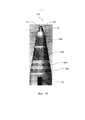
- на Фиг. 5 показан главный вид в разрезе передающей антенны;- in FIG. 5 shows a main sectional view of a transmitting antenna;
- На Фиг. 6 схематично показан первый режим передачи передающей антенны;- In FIG. 6 schematically shows a first transmission mode of a transmitting antenna;
- На Фиг. 7 схематично показан второй режим передачи передающей антенны;- In FIG. 7 schematically shows a second transmission mode of a transmitting antenna;
- На Фиг. 8 схематично показан третий режим передачи передающей антенны;- In FIG. 8 schematically shows a third transmission mode of a transmitting antenna;
- на Фиг. 9 схематично показан вид сбоку в разрезе приемной антенны;- in FIG. 9 is a schematic cross-sectional side view of a receiving antenna;
- На Фиг. 10 показана корабельная мачта с бистатической РЛС, приведенной на Фиг. 1;- In FIG. 10 shows a ship mast with a bistatic radar shown in FIG. one;
- На Фиг. 11 показано наземное транспортное средство, оснащенное бистатической РЛС, приведенной на Фиг. 1.- In FIG. 11 shows a land vehicle equipped with a bistatic radar shown in FIG. one.
[0010] На прилагаемых чертежах одинаковые или аналогичные элементы указываются теми же цифровыми позиционными обозначениями.[0010] In the accompanying drawings, the same or similar elements are indicated by the same reference numerals.
[0011] На Фиг. 1 показана функциональная блок-схема бистатической РЛС 1, содержащей передающую антенну 20 и приемную антенну 30. На конкретном приведенном примере и, таким образом, без наложения каких-либо ограничений, бистатическая РЛС 1 представляет собой РЛС на военном корабле. Однако следует отметить, что доктрины настоящего описания неограниченно применимы к конкретным областям применения бистатической РЛС 1, при этом бистатическая РЛС 1, на которую приводится ссылка в настоящем описании, может быть любой РЛС, которую можно применять, например, в телекоммуникационной отрасли, в гражданской авиации, в приборах для научных измерений.[0011] In FIG. 1 shows a functional block diagram of a
[0012] Бистатическая РЛС 1 содержит активную передающую ФАР 20, выполненную с возможностью излучения радиочастотного (РЧ) выходного сигнала 40. Активная передающая ФАР 20 содержит цилиндрическую, коническую или имеющую форму усеченного конуса решетку из колонок 21 активных передающих модулей 22. На примере, приведенном на чертежах, решетка из колонок 21 активных передающих модулей 22 является, в частности, решеткой, имеющей форму усеченного конуса, с основанием в форме окружности, где колонки 21 активных передающих модулей 22 направляются по образующей вышеупомянутого усеченного конуса.[0012] The
[0013] Например, вышеупомянутая решетка колонок 21 передающих модулей 22 содержит сто колонок 21 активных передающих модулей 22 таким образом, что число активных передающих модулей 22 передающей антенны равно, например, ста шестидесяти.[0013] For example, the aforementioned array of
[0014] Предпочтительно каждая из колонок 21 представляет собой блок, физически независимый от других, который крепится внутри опорной конструкции 27 передающей антенны 20, выполненной, например, из углеродного волокна или алюминия. Такая опорная конструкция 27 имеет, например, пазы (выполненные в виде сквозных отверстий в форме паза), к каждому из которых крепится соответствующая колонка 21 активных передающих модулей 22. Согласно одному из вариантов осуществления изобретения, вышеупомянутая опорная конструкция 27 закрывается обтекателем, не показанным на рисунках, налагаемым сверху и соприкасающимся с опорной конструкцией 27, при этом данный обтекатель может изготавливаться из материала, пригодного для работы в качестве полосового фильтра для части спектра требуемых частот. Например, обтекатель изготавливается из кевлара или стекловолокна.[0014] Preferably, each of the
[0015] Как показано на Фиг. 1, согласно одному из вариантов осуществления изобретения, каждый активный передающий модуль 22 передающей антенны 20 содержит каскадом вход, выполненный так, чтобы принимать модулированный передаваемый РЧ сигнал RF_t, фазовращатель 24, выполненный с возможностью осуществления задержки фазы упомянутого модулированного сигнала RF_t, усилитель мощности 25 (по этой причине передающая антенна определяется как «активная ФАР») и передающий антенный элемент 23. Передающий антенный элемент 23 представляет собой, например, микрополосковую антенну или дипольную антенну. Бистатическая РЛС 1 содержит, например, генератор 4 сигналов для подачи на каждый активный передающий модуль 22 передаваемого модулированного РЧ сигнала RF_t.[0015] As shown in FIG. 1, according to one embodiment of the invention, each
[0016] Кроме того, бистатическая РЛС 1 содержит планировщик 2 блока активности РЛС, выполненный с возможностью управления генератором 4 сигналов и передающей антенной 20. Например, в каждом активном передающем модуле 22 фазовращатель 24 выполняется с возможностью принимать на входе цифровой сигнал управления, подаваемый на выход блоком 2 планировщика для управления задержкой фазы, создаваемой фазовращателем 24 в модулированном РЧ сигнале RF_t.[0016] In addition, the
[0017] Кроме того, бистатическая РЛС 1 включает в себя приемную антенну 30, содержащую имеющую форму усеченного конуса решетку колонок 31 приемных модулей 32, направленных по образующей усеченного конуса. Как показано на рис 9, согласно предпочтительному варианту осуществления, вышеупомянутый усеченный конус имеет телесный угол апертуры α от 10° до 60°, включая крайние значения. Например, упомянутый телесный угол апертуры α равен или приблизительно равен 30°.[0017] In addition, the
[0018] Каждый приемный модуль 32 содержит каскадом приемный антенный элемент 33, аналоговый усилитель 34 и аналогово-цифровой преобразователь (АЦП) 36, выполненный с возможностью подавать на выход цифровые выборки. Предпочтительно аналоговый усилитель 34 является малошумящим усилителем. Каждый приемный антенный элемент 33 является, например, микрополосковой антенной или диполем. АЦП является, например, восьми- или шестнадцатибитовым преобразователем.[0018] Each
[0019] Согласно одному из вариантов осуществления, каждый приемный модуль 32 содержит перед АЦП 36 низкочастотный преобразовательный блок 35, например, смеситель, выполненный с возможностью преобразования принимаемого сигнала в полосу частот или промежуточную частоту (ПЧ). С этой целью каждый приемный модуль 32 выполняется с возможностью принимать на входе РЧ сигнал RF_o, подаваемый на выход генератором 4 сигналов. Следует помнить, что некоторые элементы приемного модуля 32 могут дублироваться для обеспечения выборки фазовой части и квадратурной части сигнала, принимаемого антенным элементом 33.[0019] According to one embodiment, each receive
[0020] Предпочтительно каждая из колонок 31 или каждый из приемных модулей 32 являются блоком, физически независимым от других блоков, и крепятся внутри опорной конструкции 37 приемной антенны 30, например, имеющей форму усеченного конуса и, например, выполненной из углеродных волокон или алюминия. Такая опорная конструкция 37 имеет, например, пазы (выполненные как сквозные отверстия в форме паза), в каждом из которых крепится соответствующая колонка 31 приемных модулей 32. Согласно одному из вариантов осуществления, вышеупомянутая опорная конструкция 37 закрывается обтекателем, не показанным на рисунках, надетым сверху и находящимся в соприкосновении с опорной конструкцией 37, при этом обтекатель может быть выполнен из материала, пригодного для работы в качестве полосового фильтра для части спектра требуемых частот. Обтекатель может изготавливаться, например, из кевлара или стекловолокна.[0020] Preferably, each of the
[0021] Если обе опорные конструкции 27 и 37 физически наложены друг на друга (т.е. надеты одна на верх другой), можно предусмотреть один обтекатель, закрывающий и передающую антенну 20, и приемную антенну 30.[0021] If both
[0022] Согласно одному из вариантов осуществления, передающая антенна 20 и приемная антенна 30 являются двумя отдельными конструкциями, надетыми друг на друга коаксиально. На конкретном примере, приведенном на Фиг. 2 и 3, передающая антенна 20 и приемная антенна 30 вместе образуют непрерывную конструкцию в форме усеченного конуса. Кроме того, в частности, на неограничивающем примере, приведенном на Фиг. 2 и 3, передающая антенна 20 надета на приемную антенну 30.[0022] According to one embodiment, the transmitting
[0023] Согласно предпочтительному варианту осуществления, число приемных модулей 32 приемной антенны 30 больше, чем число активных передающих модулей 22 передающей антенны 20. Например, приемная антенна 30 содержит двести колонок 31, при этом каждая колонка содержит шестьдесят четыре приемных модуля 32. В данном примере приемная антенна содержит двенадцать тысяч восемьсот приемных модулей 32 (в то время как в вышеприведенном примере передающая антенна 20 включает в себя тысячу шестьсот передающих модулей 22, число приемных модулей 32, следовательно, равно восьмикратному числу передающих модулей 22). Также число приемных модулей 32 в той же колонке 31 приемной антенны 30 предпочтительно больше, чем число передающих модулей 22 в той же колонке 21 передающей антенны 20.[0023] According to a preferred embodiment, the number of receiving
[0024] Согласно одному из вариантов осуществления, приемная антенна 30 содержит на каждую из колонок 31 приемных модулей 32 одну или несколько плат программируемых вентильных матриц, выполненных с возможностью обработки сигнала, принятого приемными антенными элементами 33 для подачи на выход цифровых выборок. Например, на каждую колонку 31 шестидесяти четырех приемных модулей 32 предусматривается шестнадцать плат программируемых вентильных матриц, каждая из которых оперативно подсоединена к четырем соответствующим приемным антенным элементам 33. Также может предусматриваться колонка концентратора данных, выполненная с возможностью осуществлять сбор цифровых выборок, подаваемых на выход со всех приемных модулей 32, принадлежащих той же колонке 31, для концентрации упомянутых выборок в одном или нескольких сигналах.[0024] According to one embodiment, the receiving
[0025] Бистатическая РЛС 1 включает в себя, кроме того, полностью цифровой диаграммообразующий блок 3, выполненный с возможностью приема на входе и числовой обработки цифровых выборок, подаваемых на выход приемной антенной 30. В частности, такой блок 3 содержит цифровой процессор, который при приеме весовых множителей W на входе выполнен с возможностью рассчитывать разные взвешенные линейные сочетания вышеупомянутых цифровых выборок, подаваемых на выход приемной антенной 30. Согласно варианту осуществления, в котором предусматриваются колонки концентраторов в приемной антенне 30, возможно выполнить оптоволоконное соединение между колонками концентраторов и полностью цифровым диаграммообразующим блоком 3.[0025] The
[0026] Согласно одному из вариантов осуществления, бистатическая РЛС 1 содержит процессор 5 сигналов, оперативно подключенный к планировщику 2 и к полностью цифровому диаграммообразующему блоку 3 и выполненный с возможностью подавать на диаграммообразующий блок 3 весовые множители W и принимать на входе с последнего рассчитанные взвешенные линейные сочетания. Каждое линейное сочетание соответствует лучу приемной антенны, а весовые множители выбираются предпочтительно, также для того, чтобы определить наведение луча приемной антенны и чтобы создать приемные «дыры» в направлениях, которые имеют высокий уровень возмущений окружающей среды. Число импульсов и синхронизация при передаче планируются блоком 2 планировщика как функция продолжающейся активности РЛС, которая автоматически обновляется в функции обработки в процессоре 5 сигналов.[0026] According to one embodiment, the
[0027] В дополнение к процессору 5 сигналов можно предусмотреть, чтобы бистатическая РЛС 1 содержала кроме этого еще и процессор 6 данных, оперативно подключенный к процессору 5 сигналов, а также командно-управляющий пульт 7, оперативно подключенный к процессору 6 данных.[0027] In addition to the
[0028] Согласно еще одному варианту осуществления, полностью цифровой диаграммообразующий блок 3 выполнен так, чтобы производить числовую обработку цифровых выборок для цифрового синтезирования нескольких одновременных и независимых принимаемых лучей.[0028] According to another embodiment, the all-digital
[0029] Как видно на Фиг. 6 и 7, согласно одному из вариантов осуществления, блок 2 планировщика активности РЛС выполнен с возможностью управления передающей антенной 20, приемной антенной 30 и полностью цифровым диаграммообразующим блоком 3 согласно первому рабочему режиму, при котором передающая антенна 20 управляется так, что выходной РЧ сигнал 40 (т.е. излучаемый сигнал) имеет N направленных передаваемых лучей 41, где N - целое число больше единицы или равное единице, при этом если N больше единицы, упомянутые лепестки 41 являются одновременными, т.е. излучаемыми одновременно.[0029] As seen in FIG. 6 and 7, according to one embodiment, the radar
[0030] Направлением наведения и апертурой каждого направленного передаваемого луча 41 можно управлять по углу возвышения и/или азимуту с помощью блока 2 планировщика активности РЛС. В частности, каждый направленный передаваемый луч 41, например, карандашный, образуется соответствующей подрешеткой соседних колонок 21 активных передающих модулей 22, выбираемой электронным способом и центрируемой по азимуту относительно направления наведения соответствующего направленного передаваемого луча 41. Вышеупомянутые подрешетки соседних колонок 21 не имеют общих колонок, т.е. они не находятся одни над другими.[0030] The guidance direction and aperture of each directional transmitted
[0031] На примере, приведенном на Фиг. 6, сигнал 40, излучаемый передающей антенной 20, включает в себя четыре одновременных направленных лучей 41 (следовательно, N=4), например, для осуществления бистатической РЛС 1 наблюдения или отслеживания одной или нескольких дальних целей (например, на дистанциях порядка 80-100 км). Для получения такого излучаемого сигнала передающая антенна 20 разделается, например, на четыре подрешетки колонок 21, при этом каждая из этих подрешеток служит для излучения соответствующего направленного луча 41. При ведении дальнего наблюдения направленные передаваемые лучи 41 поворачиваются в азимутальной плоскости, заставляя поворачиваться подрешетки электронным способом с тем, чтобы обеспечить обзор в пределах 360°. Сканирование по азимуту осуществляется управлением по фазе передающими модулями 22, в частности, фазовращателями 24.[0031] In the example of FIG. 6, the
[0032] На примере, приведенном на Фиг. 7, сигнал 40, излучаемый передающей антенной 20, содержит десять одновременных направленных лучей 41 (следовательно, N=10), например, чтобы бистатической РЛС 1 осуществить одновременное отслеживание нескольких целей на средней дистанции (например, на дистанциях до порядка 30-40 км).[0032] In the example of FIG. 7, the
[0033] На вышеупомянутом рабочем режиме приемная антенна 30 и полностью цифровой диаграммообразующий блок 3 управляются планировщиком 2 активности РЛС для создания для каждых упомянутых N направленных передаваемых лучей 41 соответствующих нескольких М одновременных принимаемых лучей, где М - целое число больше единицы и меньше числа колонок 31 приемных модулей 32 или равно ему. Следовательно, полностью цифровой диаграммообразующий блок 3 предназначен для одновременного синтезирования М×N принимаемых лучей.[0033] In the aforementioned operating mode, the receiving
[0034] Согласно преимущественному варианту осуществления, каждые несколько М принимаемых лучей таковы, что они наводятся в направлении соответствующего направленного передаваемого луча 41 и образуются одной или несколькими соответствующими подрешетками колонок 31 приемных модулей 32, выбираемыми электронным способом и центрируемыми по азимуту относительно направления наведения соответствующего направленного передаваемого луча 41. Таким способом возможно с большим преимуществом избежать потерь при сканировании в горизонтальной плоскости. Вышеупомянутая подрешетка колонок 31 приемных модулей 32 может также иметь общие колонки 31, т.е. они могут быть частично наложенными друг на друга.[0034] According to an advantageous embodiment, every few M received beams are such that they are guided in the direction of the corresponding directional transmitted
[0035] Также следует отметить, что на первом рабочем режиме бистатическая РЛС реализована так, чтобы осуществлять наблюдение и отслеживание, а блок 2 планировщика служит для управления передающей антенной 20, приемной антенной 30 и полностью цифровым диаграммообразующим блоком 3 с тем, чтобы электронным способом сканировать наблюдаемый сектор посредством упомянутых направленного передаваемого луча 41 и принимаемого луча, при этом азимутальное сканирование осуществляется электронным выбором упомянутых подрешеток колонок 21, 31 (передающих и приемных модулей), в то время как сканирование по углу возвышения осуществляется управлением фазой.[0035] It should also be noted that in the first operating mode, the bistatic radar is implemented to monitor and track, and the
[0036] Согласно еще одному варианту осуществления, блок 2 планировщика активности РЛС выполнен с возможностью управления передающей антенной 20, приемной антенной 30 и полностью цифровым диаграммообразующим блоком 3 по второму рабочему режиму с выбором поочередно с первым. На втором рабочем режиме передающая антенна 20 управляется так, что выходной РЧ сигнал 40 обладает расфокусированной диаграммой 43 направленности излучения, имеющей полусферическую или практически полусферическую форму, как показано, например, на Фиг. 8. На конкретном примере, приведенном на Фиг. 8, диаграмма направленности излучения имеет форму с охватом по азимуту равным 360°, а по углу возвышения 70°, а также определяема в таком отношении, как практически полусферическая (омега-луч).[0036] According to yet another embodiment, the radar
[0037] На втором рабочем режиме приемная антенна 30 управляется одновременным наведением одной или нескольких совокупностей М принимаемых лучей в одном или нескольких соответствующих направлениях, в которых отмечалось наличие цели. Преимущественно можно осуществлять с помощью бистатической РЛС 1 одновременное отслеживание множественных целей на малых дистанциях (например, на дистанциях до 10 км). В общем случае можно предусмотреть, чтобы на втором рабочем режиме бистатическая РЛС была реализована для выполнения:[0037] In the second operating mode, the receiving
- преследования цели или одновременного преследования нескольких целей;- pursuing a goal or simultaneously pursuing several goals;
- и/или направления дистанционно управляемого оружия или одновременного направления нескольких единиц дистанционно управляемого оружия;- and / or the direction of a remotely controlled weapon or the simultaneous direction of several units of a remotely controlled weapon;
- и/или нацеливания артиллерийской системы или одновременного нацеливания нескольких артиллерийских систем.- and / or targeting an artillery system or simultaneously targeting multiple artillery systems.
[0038] Согласно одному из вариантов осуществления, переход между первым рабочим режимом и вторым рабочим режимом и наоборот является постепенным, например, с постепенным расфокусированием направленных лучей 41, как показано на Фиг. 7, до тех пор, пока не будет получен передаваемый сигнал, имеющий диаграмму направленности излучения типа, приведенного на Фиг. 8.[0038] According to one embodiment, the transition between the first operating mode and the second operating mode and vice versa is gradual, for example, with the gradual defocusing of the directed beams 41, as shown in FIG. 7 until a transmit signal having a radiation pattern of the type shown in FIG. 8.
[0039] Альтернативно или в дополнение ко второму рабочему режиму можно предусмотреть еще один рабочий режим, в котором передаваемый сигнал будет иметь диаграмму направленности излучения дискового профиля, с охватом по азимуту 360°, по амплитуде 5°-10° и переменным наведением по углу возвышения (луч 2![]()
![]()
[0040] На всех рабочих режимах, описанных выше, возможно сохранение радиолокационного эхо-сигнала в цифровой форме и обработка его с помощью полностью цифрового диаграммообразующего блока 3 в отложенный момент времени.[0040] In all the operating modes described above, it is possible to save the radar echo in digital form and process it using a fully
[0041] Это позволяет снизить число повторяющихся каналов (число которых в случае обработки в реальном масштабе времени равнялось бы числу принимаемых лучей), так как каждый канал может последовательно обрабатывать несколько принимаемых лучей с разным наведением, полученных в отложенный момент времени с помощью цифрового диаграммообразующего блока 3, обрабатывающего сохраненный радиолокационный эхо-сигнал. Так как передача мощности не требуется во время отложенной обработки, то в данном случае также получают снижение рабочего цикла передаваемого сигнала. Очевидно, данный рабочий режим определяет увеличение времени обновления радиолокационных данных и может, тем самым, применяться тогда, когда данный параметр не имеет значения для работы РЛС или когда он важен для сведения к минимуму времени передачи в целях снижения вероятности перехвата сигнала РЛС.[0041] This allows to reduce the number of repeating channels (the number of which in the case of processing in real time would equal the number of received rays), since each channel can sequentially process several received rays with different guidance received at a delayed time using a digital block-forming
[0042] Как показано на примере, приведенном на Фиг. 10, возможно встроить одну или несколько бистатических РЛС, описанных выше, в корабельную мачту 50. Корабельная мачта 50 или по меньшей мере ее участок предпочтительно установлены на механически стабилизированной платформе.[0042] As shown in the example of FIG. 10, it is possible to integrate one or more bistatic radars described above into the
[0043] Как показано на примере, приведенном на Фиг. 10, на вершине корабельной мачты имеется антенна радиоэлектронных средств наблюдения. Под ней на корабельной мачте 50 располагается передающая антенна 20 и приемная антенна 30 бистатической РЛС 1, описанной выше, например, работающей на частоте 10 ГГц.[0043] As shown in the example of FIG. 10, at the top of the ship’s mast there is an antenna of electronic surveillance equipment. Below it, on the
[0044] Согласно одному из вариантов осуществления, корабельная мачта 50 содержит еще одну имеющую форму усеченного конуса передающую антенну 20а, аналогичную передающей антенне 20, описанной выше, и которая является, например, антенной средств радиоэлектронного подавления (РЭП), работающей в диапазоне частот 2-18 ГГц.[0044] According to one embodiment, the
[0045] Согласно одному из вариантов осуществления, корабельная мачта 50 содержит еще одну имеющую форму усеченного конуса передающую антенну 20b, аналогичную передающей антенне 20, описанной выше, и которая является, например, двойной антенной, выполненной с возможностью выполнять функцию передающей антенны РЛС дальнего действия (работающей, например, на частоте 1,3 ГГц), а также функцию передающей антенны радиолокационной системы опознавания государственной принадлежности цели, работающей, например, на частоте 1,06 ГГц. В данном варианте осуществления корабельная мачта 50 дополнительно содержит следующее:[0045] According to one embodiment, the
- еще одну имеющую форму усеченного конуса приемную антенну 30а, аналогичную приемной антенне 30, описанной выше, и которая, например, является приемной антенной вышеупомянутой РЛС дальнего действия, содержащей передающую антенну 20b;- another truncated cone-shaped
- еще одну имеющую форму усеченного конуса приемную антенну 30b, аналогичную приемной антенне 30, описанной выше, и которая является, например, приемной антенной вышеупомянутой радиолокационной системы опознавания государственной принадлежности цели, содержащей передающую антенну 20b.- another truncated cone-shaped
[0046] В основании корабельной мачты 50 может быть предусмотрено помещение управления для размещения в нем командно-управляющего пульта 7 согласно блок-схеме, приведенной на Фиг. 1, а также, возможно, другого программно-аппаратного комплекса, выполненного с возможностью обработки сигналов, связанных с работой передающей и приемной антенн, описанных выше.[0046] At the base of the
[0047] Из Фиг. 11 можно увидеть, что бистатическая РЛС 1 описанного выше типа может устанавливаться на борту сухопутного транспортного средства 60, например, в верхней части телескопической колонны 61. На конкретном приведенном примере вышеупомянутое сухопутное транспортное средство 60 - это грузовой автомобиль, оснащенный обитаемым контейнером, в котором расположен командно-управляющий пульт 7 согласно блок-схеме, представленной на Фиг. 1, а также, возможно, другой программно-аппаратный комплекс, выполненный с возможностью обработки сигналов, связанных с работой бистатической РЛС 1. [0047] From FIG. 11, it can be seen that the
[0048] Из вышеприведенного описания очевидно, как бистатическая РЛС описанного выше типа позволяет достичь вышеупомянутых целей по сравнению с существующим уровнем техники.[0048] From the foregoing description, it is obvious how a bistatic radar of the type described above can achieve the aforementioned objectives in comparison with the prior art.
[0049] Без ущерба принципу настоящего изобретения варианты осуществления и детали конструкции могут меняться в широком диапазоне относительно описанного и иллюстрируются чисто посредством неограничивающего примера, не уходя, следовательно, от объема изобретения, как определено в прилагаемой формуле изобретения.[0049] Without prejudice to the principle of the present invention, embodiments and structural details may vary widely from that described and are illustrated purely by way of non-limiting example, without departing, therefore, from the scope of the invention as defined in the attached claims.
Claims (29)
Applications Claiming Priority (3)
| Application Number | Priority Date | Filing Date | Title |
|---|---|---|---|
| ITRM2014A000005 | 2014-01-09 | ||
| ITRM20140005 | 2014-01-09 | ||
| PCT/IT2014/000310 WO2015104728A1 (en) | 2014-01-09 | 2014-11-24 | Bistatic radar |
Publications (2)
| Publication Number | Publication Date |
|---|---|
| RU2016122083A RU2016122083A (en) | 2018-02-14 |
| RU2658671C2 true RU2658671C2 (en) | 2018-06-22 |
Family
ID=50391293
Family Applications (1)
| Application Number | Title | Priority Date | Filing Date |
|---|---|---|---|
| RU2016122083A RU2658671C2 (en) | 2014-01-09 | 2014-11-24 | Bistatic radar station |
Country Status (11)
| Country | Link |
|---|---|
| US (1) | US20160327641A1 (en) |
| EP (1) | EP3092508B1 (en) |
| AU (1) | AU2014376819B2 (en) |
| BR (1) | BR112016014434B1 (en) |
| CA (1) | CA2932430C (en) |
| DK (1) | DK3092508T3 (en) |
| ES (1) | ES2667405T3 (en) |
| IL (1) | IL246360B (en) |
| PL (1) | PL3092508T3 (en) |
| RU (1) | RU2658671C2 (en) |
| WO (1) | WO2015104728A1 (en) |
Cited By (2)
| Publication number | Priority date | Publication date | Assignee | Title |
|---|---|---|---|---|
| RU2713219C1 (en) * | 2019-07-04 | 2020-02-04 | Федеральное государственное автономное образовательное учреждение высшего образования "Санкт-Петербургский государственный электротехнический университет "ЛЭТИ" им. В.И. Ульянова (Ленина) | Mobile coherent radar system |
| RU2749652C2 (en) * | 2019-11-25 | 2021-06-16 | Общество с ограниченной ответственностью "ГОУДИДЖИТАЛ" | Indoor television antenna |
Families Citing this family (12)
| Publication number | Priority date | Publication date | Assignee | Title |
|---|---|---|---|---|
| US10056699B2 (en) | 2015-06-16 | 2018-08-21 | The Mitre Cooperation | Substrate-loaded frequency-scaled ultra-wide spectrum element |
| US9991605B2 (en) | 2015-06-16 | 2018-06-05 | The Mitre Corporation | Frequency-scaled ultra-wide spectrum element |
| US10439851B2 (en) * | 2016-09-20 | 2019-10-08 | Ohio State Innovation Foundation | Frequency-independent receiver and beamforming technique |
| SG11201906607RA (en) | 2016-10-17 | 2019-08-27 | Fincantieri Spa | Radar system |
| US10854993B2 (en) | 2017-09-18 | 2020-12-01 | The Mitre Corporation | Low-profile, wideband electronically scanned array for geo-location, communications, and radar |
| KR102516365B1 (en) * | 2018-05-25 | 2023-03-31 | 삼성전자주식회사 | Method and apparatus for controlling radar of vehicle |
| US10886625B2 (en) | 2018-08-28 | 2021-01-05 | The Mitre Corporation | Low-profile wideband antenna array configured to utilize efficient manufacturing processes |
| RU2713103C1 (en) * | 2018-09-28 | 2020-02-03 | Акционерное общество "Всероссийский научно-исследовательский институт радиотехники" | Method of generating beam pattern of transmitting active antenna array and axisymmetric active phased antenna array based thereon |
| CN111755825B (en) * | 2020-06-23 | 2021-10-26 | 电子科技大学 | Broadband wide-angle scanning phased array antenna based on stacked patch type matching layer |
| CN112505434B (en) * | 2020-11-24 | 2022-08-12 | 中国电子科技集团公司第三十八研究所 | Method for testing passive array antenna beam scanning characteristics |
| CA3209399A1 (en) * | 2021-02-24 | 2022-09-01 | Michael Thomas Pace | System and method for a digitally beamformed phased array feed |
| CN112910521B (en) * | 2021-02-27 | 2022-04-05 | 中电万维信息技术有限责任公司 | Deep learning-based MIMO mixed beam forming method |
Citations (8)
| Publication number | Priority date | Publication date | Assignee | Title |
|---|---|---|---|---|
| JP2000171544A (en) * | 1998-12-08 | 2000-06-23 | Nec Corp | Phased array radar |
| US6388603B1 (en) * | 1980-12-11 | 2002-05-14 | Raytheon Company | System and method for bistatically determining altitude and slant range to a selected target |
| RU2215303C2 (en) * | 2001-09-28 | 2003-10-27 | Федеральное государственное унитарное предприятие "Научно-исследовательский институт измерительных приборов" | Method of airspace control |
| RU2285939C1 (en) * | 2005-02-10 | 2006-10-20 | Открытое акционерное общество "Научно-исследовательский институт измерительных приборов" (ОАО "НИИИП") | Method for controlling airspace, irradiated by external radiation sources, and radiolocation station for realization of said method |
| RU2293405C1 (en) * | 2005-08-11 | 2007-02-10 | Федеральное государственное унитарное предприятие "Государственный московский завод "Салют" | Shipboard radar station |
| RU2296343C1 (en) * | 2005-10-19 | 2007-03-27 | Воронежское конструкторское бюро антенно-фидерных устройств (открытое акционерное общество) | Mode of detection of an object |
| EP1814197A1 (en) * | 2006-01-24 | 2007-08-01 | Siemens S.p.A. | An antenna arrangement having unevenly separated elements |
| RU2324197C2 (en) * | 2006-02-20 | 2008-05-10 | Федеральное Государственное Унитарное Предприятие "Нижегородский Научно-Исследовательский Институт Радиотехники" | Radar complex |
Family Cites Families (5)
| Publication number | Priority date | Publication date | Assignee | Title |
|---|---|---|---|---|
| US3697994A (en) * | 1971-07-19 | 1972-10-10 | Us Navy | Automatic beam steering technique for cylindrical-array radar antennas |
| JPH06249945A (en) * | 1993-02-25 | 1994-09-09 | Mitsubishi Electric Corp | Radar device |
| DE102005029090A1 (en) * | 2005-06-23 | 2006-12-28 | Ewation Gmbh | Antenna assembly for use in loop antenna system of ship, has antenna structure and mast which is constructed from truncated cone shaped structures, where surface normal of antenna structures forms specific angle with normal in mast axis |
| US8284109B2 (en) * | 2007-10-31 | 2012-10-09 | Lockheed Martin Corporation | Telescoping radar array |
| US8344943B2 (en) * | 2008-07-28 | 2013-01-01 | Physical Domains, LLC | Low-profile omnidirectional retrodirective antennas |
-
2014
- 2014-11-24 DK DK14838802.8T patent/DK3092508T3/en active
- 2014-11-24 WO PCT/IT2014/000310 patent/WO2015104728A1/en active Application Filing
- 2014-11-24 RU RU2016122083A patent/RU2658671C2/en active
- 2014-11-24 US US15/110,462 patent/US20160327641A1/en not_active Abandoned
- 2014-11-24 EP EP14838802.8A patent/EP3092508B1/en active Active
- 2014-11-24 BR BR112016014434-1A patent/BR112016014434B1/en active IP Right Grant
- 2014-11-24 AU AU2014376819A patent/AU2014376819B2/en active Active
- 2014-11-24 CA CA2932430A patent/CA2932430C/en active Active
- 2014-11-24 ES ES14838802.8T patent/ES2667405T3/en active Active
- 2014-11-24 PL PL14838802T patent/PL3092508T3/en unknown
-
2016
- 2016-06-20 IL IL246360A patent/IL246360B/en active IP Right Grant
Patent Citations (8)
| Publication number | Priority date | Publication date | Assignee | Title |
|---|---|---|---|---|
| US6388603B1 (en) * | 1980-12-11 | 2002-05-14 | Raytheon Company | System and method for bistatically determining altitude and slant range to a selected target |
| JP2000171544A (en) * | 1998-12-08 | 2000-06-23 | Nec Corp | Phased array radar |
| RU2215303C2 (en) * | 2001-09-28 | 2003-10-27 | Федеральное государственное унитарное предприятие "Научно-исследовательский институт измерительных приборов" | Method of airspace control |
| RU2285939C1 (en) * | 2005-02-10 | 2006-10-20 | Открытое акционерное общество "Научно-исследовательский институт измерительных приборов" (ОАО "НИИИП") | Method for controlling airspace, irradiated by external radiation sources, and radiolocation station for realization of said method |
| RU2293405C1 (en) * | 2005-08-11 | 2007-02-10 | Федеральное государственное унитарное предприятие "Государственный московский завод "Салют" | Shipboard radar station |
| RU2296343C1 (en) * | 2005-10-19 | 2007-03-27 | Воронежское конструкторское бюро антенно-фидерных устройств (открытое акционерное общество) | Mode of detection of an object |
| EP1814197A1 (en) * | 2006-01-24 | 2007-08-01 | Siemens S.p.A. | An antenna arrangement having unevenly separated elements |
| RU2324197C2 (en) * | 2006-02-20 | 2008-05-10 | Федеральное Государственное Унитарное Предприятие "Нижегородский Научно-Исследовательский Институт Радиотехники" | Radar complex |
Cited By (2)
| Publication number | Priority date | Publication date | Assignee | Title |
|---|---|---|---|---|
| RU2713219C1 (en) * | 2019-07-04 | 2020-02-04 | Федеральное государственное автономное образовательное учреждение высшего образования "Санкт-Петербургский государственный электротехнический университет "ЛЭТИ" им. В.И. Ульянова (Ленина) | Mobile coherent radar system |
| RU2749652C2 (en) * | 2019-11-25 | 2021-06-16 | Общество с ограниченной ответственностью "ГОУДИДЖИТАЛ" | Indoor television antenna |
Also Published As
| Publication number | Publication date |
|---|---|
| BR112016014434B1 (en) | 2022-09-13 |
| PL3092508T3 (en) | 2018-08-31 |
| RU2016122083A (en) | 2018-02-14 |
| DK3092508T3 (en) | 2018-05-07 |
| CA2932430C (en) | 2021-12-28 |
| AU2014376819A1 (en) | 2016-06-16 |
| US20160327641A1 (en) | 2016-11-10 |
| ES2667405T3 (en) | 2018-05-10 |
| EP3092508A1 (en) | 2016-11-16 |
| EP3092508B1 (en) | 2018-01-31 |
| IL246360A0 (en) | 2016-08-31 |
| IL246360B (en) | 2020-03-31 |
| BR112016014434A2 (en) | 2017-08-08 |
| AU2014376819B2 (en) | 2018-04-19 |
| WO2015104728A1 (en) | 2015-07-16 |
| CA2932430A1 (en) | 2015-07-16 |
Similar Documents
| Publication | Publication Date | Title |
|---|---|---|
| RU2658671C2 (en) | Bistatic radar station | |
| RU2740218C2 (en) | Radar system | |
| US8432307B2 (en) | Agile-beam radar notably for the obstacle ‘sense and avoid’ function | |
| JP6546003B2 (en) | Radar system and radar signal processing method | |
| US5257031A (en) | Multibeam antenna which can provide different beam positions according to the angular sector of interest | |
| EP3977565A2 (en) | Phased array antenna with isotropic and non-isotropic radiating and omnidirectional and non-omnidirectional receiving elements | |
| Carta et al. | Implementation of the ubiquitous radar concept with a conformal array | |
| JP2018004538A (en) | Radio guidance device and radio guidance method | |
| WO1986000760A1 (en) | Multibeam antenna, which can provide different beam positions according to the angular sector of interest | |
| RU2348001C1 (en) | Anti-aircraft cannon-missile military vehicle | |
| Cecchini et al. | MMW active phased array seeker project for hit to kill engagement | |
| KR101790123B1 (en) | Semi-active guided air vehicle for intercepting aircraft | |
| KR101790124B1 (en) | Semi-active aircraft intercept system and method | |
| RU82044U1 (en) | ALTITUDE DETECTOR - BBO | |
| Leonov | History of monopulse radar in the USSR | |
| EP3737966A1 (en) | Radar systems | |
| RU2713159C1 (en) | Method of forming circular area of electronic scanning of cylindrical phased antenna array with increased rate of view | |
| RU2686455C1 (en) | Mobile objects target distribution system | |
| Hu et al. | Design and Simulation of Conformal Phased Array Antenna | |
| Sankowski et al. | Multifunction C-band radar development in Poland: Electronically scanned array technology | |
| Pell | A review of system performance requirements for phased array antennas | |
| WO2019138037A1 (en) | Radar systems | |
| Yu et al. | Electronic protection for digital shared aperture array radar | |
| Klembowski et al. | Trends in radar technology and PIT achievements |