RU2657227C2 - Beverage preparation device - Google Patents
Beverage preparation device Download PDFInfo
- Publication number
- RU2657227C2 RU2657227C2 RU2015146862A RU2015146862A RU2657227C2 RU 2657227 C2 RU2657227 C2 RU 2657227C2 RU 2015146862 A RU2015146862 A RU 2015146862A RU 2015146862 A RU2015146862 A RU 2015146862A RU 2657227 C2 RU2657227 C2 RU 2657227C2
- Authority
- RU
- Russia
- Prior art keywords
- water
- water tank
- door
- beverage
- electronic unit
- Prior art date
Links
Images


Classifications
-
- A—HUMAN NECESSITIES
- A47—FURNITURE; DOMESTIC ARTICLES OR APPLIANCES; COFFEE MILLS; SPICE MILLS; SUCTION CLEANERS IN GENERAL
- A47J—KITCHEN EQUIPMENT; COFFEE MILLS; SPICE MILLS; APPARATUS FOR MAKING BEVERAGES
- A47J31/00—Apparatus for making beverages
- A47J31/005—Portable or compact beverage making apparatus, e.g. for travelling, for use in automotive vehicles
-
- A—HUMAN NECESSITIES
- A47—FURNITURE; DOMESTIC ARTICLES OR APPLIANCES; COFFEE MILLS; SPICE MILLS; SUCTION CLEANERS IN GENERAL
- A47J—KITCHEN EQUIPMENT; COFFEE MILLS; SPICE MILLS; APPARATUS FOR MAKING BEVERAGES
- A47J31/00—Apparatus for making beverages
- A47J31/44—Parts or details or accessories of beverage-making apparatus
- A47J31/54—Water boiling vessels in beverage making machines
- A47J31/56—Water boiling vessels in beverage making machines having water-level controls; having temperature controls
-
- A—HUMAN NECESSITIES
- A47—FURNITURE; DOMESTIC ARTICLES OR APPLIANCES; COFFEE MILLS; SPICE MILLS; SUCTION CLEANERS IN GENERAL
- A47J—KITCHEN EQUIPMENT; COFFEE MILLS; SPICE MILLS; APPARATUS FOR MAKING BEVERAGES
- A47J31/00—Apparatus for making beverages
- A47J31/24—Coffee-making apparatus in which hot water is passed through the filter under pressure, i.e. in which the coffee grounds are extracted under pressure
- A47J31/34—Coffee-making apparatus in which hot water is passed through the filter under pressure, i.e. in which the coffee grounds are extracted under pressure with hot water under liquid pressure
- A47J31/36—Coffee-making apparatus in which hot water is passed through the filter under pressure, i.e. in which the coffee grounds are extracted under pressure with hot water under liquid pressure with mechanical pressure-producing means
- A47J31/3666—Coffee-making apparatus in which hot water is passed through the filter under pressure, i.e. in which the coffee grounds are extracted under pressure with hot water under liquid pressure with mechanical pressure-producing means whereby the loading of the brewing chamber with the brewing material is performed by the user
- A47J31/3676—Cartridges being employed
- A47J31/369—Impermeable cartridges being employed
- A47J31/3695—Cartridge perforating means for creating the hot water inlet
-
- A—HUMAN NECESSITIES
- A47—FURNITURE; DOMESTIC ARTICLES OR APPLIANCES; COFFEE MILLS; SPICE MILLS; SUCTION CLEANERS IN GENERAL
- A47J—KITCHEN EQUIPMENT; COFFEE MILLS; SPICE MILLS; APPARATUS FOR MAKING BEVERAGES
- A47J31/00—Apparatus for making beverages
- A47J31/40—Beverage-making apparatus with dispensing means for adding a measured quantity of ingredients, e.g. coffee, water, sugar, cocoa, milk, tea
- A47J31/407—Beverage-making apparatus with dispensing means for adding a measured quantity of ingredients, e.g. coffee, water, sugar, cocoa, milk, tea with ingredient-containing cartridges; Cartridge-perforating means
-
- A—HUMAN NECESSITIES
- A47—FURNITURE; DOMESTIC ARTICLES OR APPLIANCES; COFFEE MILLS; SPICE MILLS; SUCTION CLEANERS IN GENERAL
- A47J—KITCHEN EQUIPMENT; COFFEE MILLS; SPICE MILLS; APPARATUS FOR MAKING BEVERAGES
- A47J31/00—Apparatus for making beverages
- A47J31/44—Parts or details or accessories of beverage-making apparatus
- A47J31/46—Dispensing spouts, pumps, drain valves or like liquid transporting devices
- A47J31/462—Dispensing spouts, pumps, drain valves or like liquid transporting devices with an intermediate liquid storage tank
-
- A—HUMAN NECESSITIES
- A47—FURNITURE; DOMESTIC ARTICLES OR APPLIANCES; COFFEE MILLS; SPICE MILLS; SUCTION CLEANERS IN GENERAL
- A47J—KITCHEN EQUIPMENT; COFFEE MILLS; SPICE MILLS; APPARATUS FOR MAKING BEVERAGES
- A47J31/00—Apparatus for making beverages
- A47J31/44—Parts or details or accessories of beverage-making apparatus
- A47J31/60—Cleaning devices
- A47J31/605—Water filters
-
- B—PERFORMING OPERATIONS; TRANSPORTING
- B65—CONVEYING; PACKING; STORING; HANDLING THIN OR FILAMENTARY MATERIAL
- B65D—CONTAINERS FOR STORAGE OR TRANSPORT OF ARTICLES OR MATERIALS, e.g. BAGS, BARRELS, BOTTLES, BOXES, CANS, CARTONS, CRATES, DRUMS, JARS, TANKS, HOPPERS, FORWARDING CONTAINERS; ACCESSORIES, CLOSURES, OR FITTINGS THEREFOR; PACKAGING ELEMENTS; PACKAGES
- B65D41/00—Caps, e.g. crown caps or crown seals, i.e. members having parts arranged for engagement with the external periphery of a neck or wall defining a pouring opening or discharge aperture; Protective cap-like covers for closure members, e.g. decorative covers of metal foil or paper
- B65D41/02—Caps or cap-like covers without lines of weakness, tearing strips, tags, or like opening or removal devices
- B65D41/023—Caps or cap-like covers without lines of weakness, tearing strips, tags, or like opening or removal devices with integral internal sealing means
-
- B—PERFORMING OPERATIONS; TRANSPORTING
- B65—CONVEYING; PACKING; STORING; HANDLING THIN OR FILAMENTARY MATERIAL
- B65D—CONTAINERS FOR STORAGE OR TRANSPORT OF ARTICLES OR MATERIALS, e.g. BAGS, BARRELS, BOTTLES, BOXES, CANS, CARTONS, CRATES, DRUMS, JARS, TANKS, HOPPERS, FORWARDING CONTAINERS; ACCESSORIES, CLOSURES, OR FITTINGS THEREFOR; PACKAGING ELEMENTS; PACKAGES
- B65D51/00—Closures not otherwise provided for
- B65D51/16—Closures not otherwise provided for with means for venting air or gas
- B65D51/1633—Closures not otherwise provided for with means for venting air or gas whereby venting occurs by automatic opening of the closure, container or other element
- B65D51/1644—Closures not otherwise provided for with means for venting air or gas whereby venting occurs by automatic opening of the closure, container or other element the element being a valve
-
- B—PERFORMING OPERATIONS; TRANSPORTING
- B65—CONVEYING; PACKING; STORING; HANDLING THIN OR FILAMENTARY MATERIAL
- B65D—CONTAINERS FOR STORAGE OR TRANSPORT OF ARTICLES OR MATERIALS, e.g. BAGS, BARRELS, BOTTLES, BOXES, CANS, CARTONS, CRATES, DRUMS, JARS, TANKS, HOPPERS, FORWARDING CONTAINERS; ACCESSORIES, CLOSURES, OR FITTINGS THEREFOR; PACKAGING ELEMENTS; PACKAGES
- B65D81/00—Containers, packaging elements, or packages, for contents presenting particular transport or storage problems, or adapted to be used for non-packaging purposes after removal of contents
- B65D81/02—Containers, packaging elements, or packages, for contents presenting particular transport or storage problems, or adapted to be used for non-packaging purposes after removal of contents specially adapted to protect contents from mechanical damage
Abstract
Description
Область техники, к которой относится изобретениеFIELD OF THE INVENTION
Настоящее изобретение относится к бытовому прибору, служащему в качестве портативной кофеварки. Более конкретно, оно относится к портативной кофеварке, которая является прочной, компактной и может иметь различные конфигурации, зависящие от потребностей пользователя.The present invention relates to a household appliance serving as a portable coffee maker. More specifically, it relates to a portable coffee maker that is durable, compact and can have various configurations depending on the needs of the user.
Уровень техникиState of the art
В последнее время особую популярность приобрели персональные кофеварки для использования в домашних условиях. Наиболее известными примерами являются системы марок Keurig®, Senseo® и Tassimo®. В таких системах используют чашку специальной конструкции, в некоторых случаях ее описывают как таблетку, которую помещают в кофеварку, чтобы приготовить напиток путем пропускания через нее воды. За последние несколько лет рынок таких кофеварок вырос настолько, что на настоящий момент является одним из самых быстроразвивающихся сегментов национальных рынков. Потребителям нравится, что вместо заварки целого резервуара с напитком можно приготовить одну чашку кофе или чая, при этом каждый человек может насладиться горячим напитком, соответствующим его личным предпочтениям. Хотя этот рынок приобрел все увеличивающуюся популярность в области домашней бытовой техники, сейчас существует потребность предусмотреть возможность использования данных преимуществ за пределами дома.Recently, personal coffee makers for home use have gained particular popularity. The best-known examples are Keurig®, Senseo®, and Tassimo® brand systems. In such systems, a cup of special design is used, in some cases it is described as a tablet, which is placed in a coffee maker to prepare a drink by passing water through it. Over the past few years, the market for such coffee makers has grown so much that it is currently one of the fastest growing segments of national markets. Consumers like that instead of brewing a whole reservoir with a drink, one cup of coffee or tea can be prepared, and each person can enjoy a hot drink that matches his personal preferences. Although this market has gained increasing popularity in the field of home appliances, now there is a need to provide for the possibility of using these advantages outside the home.
Проблема стандартных кофеварок заключается в том, что они предназначены только для использования дома или в офисе. Их конструкция разработана специально для использования в помещении, где они остаются на одном месте, обычно на столе или на кухонной столешнице. Однако многие люди (например, строители и туристы) проводят большую часть времени на улице или в других условиях, которые являются более жесткими и требуют специально разработанных продуктов для эксплуатации в разных местах при нестандартных условиях. Данные устройства должны выдерживать частую транспортировку, хранение с другими приспособлениями и запасами, частые удары, различные погодные условия, рельефы местности, а также должны быть защищены от попадания грязи, мусора и воздействия других условий окружающей среды. Традиционные бытовые приборы не приспособлены к работе в подобных условиях. Например, многие персональные кофеварки имеют резервуары для воды, которая может легко пролиться, если устройство переносят на другое место. Их конструкция не предполагает работу вне помещения, поскольку в этом случае они должны быть сильно упрочненными, портативными и складными, и не допускающими попадания воды, грязи или мусора. Настоящее изобретение решает данную проблему, поскольку предлагает прочную, изолированную, портативную и складную систему, подходящую для приготовления напитков вне помещений. Приведенные выше ссылки и описания предшествующих проектов или изделий не являются и не должны рассматриваться как заявление или признание того, что они известны из уровня техники. В частности, обсуждение предшествующего уровня техники не относится к тому, что является общеизвестным или хорошо известным для специалистов в данной области техники, оно скорее помогает понять неочевидность настоящего изобретения, для которого определение предложений, известных из уровня техники, является лишь одной из частей.The problem with standard coffee makers is that they are designed for use only at home or in the office. Their design is specifically designed for indoor use, where they remain in one place, usually on a table or on a kitchen worktop. However, many people (for example, builders and tourists) spend most of the time on the street or in other conditions that are more stringent and require specially designed products for use in different places under unusual conditions. These devices must withstand frequent transportation, storage with other equipment and supplies, frequent shock, various weather conditions, terrain, and also must be protected from dirt, debris and other environmental conditions. Traditional household appliances are not adapted to work in such conditions. For example, many personal coffee makers have tanks for water, which can easily spill if the device is moved to another location. Their design does not imply work outdoors, since in this case they should be highly hardened, portable and folding, and not allowing the ingress of water, dirt or debris. The present invention solves this problem by providing a robust, insulated, portable and folding system suitable for preparing drinks outdoors. The above references and descriptions of previous projects or products are not and should not be construed as a statement or recognition that they are known from the prior art. In particular, the discussion of the prior art does not apply to what is well known or well known to those skilled in the art, but rather helps to understand the non-obviousness of the present invention, for which the definition of sentences known from the prior art is only one part.
Раскрытие изобретенияDisclosure of invention
Настоящее изобретение относится к приспособлению для приготовления напитков, содержащему:The present invention relates to a device for preparing drinks, comprising:
внешний корпус, имеющий дверцу системы резервуара для воды и дверцу системы приготовления напитка; причем внутри внешнего корпуса размещены резервуар для воды, система приготовления напитка и система подачи воды;an outer case having a door of a water tank system and a door of a beverage preparation system; moreover, inside the outer casing there is a water tank, a beverage preparation system and a water supply system;
внутреннюю опорную раму, поддерживающую внешний корпус;an internal support frame supporting the external housing;
изолированную систему резервуара для воды, также содержащую съемный, портативный и ударопрочный резервуар для воды с герметизируемой съемной крышкой и герметичным клапаном водяной системы, соединенным с системой подачи воды;an insulated water tank system also comprising a removable, portable, and shockproof water tank with a sealed removable lid and a sealed water system valve connected to the water supply system;
систему приготовления напитка с камерой заваривания, в которую вставляют капсулу на одну порцию;a beverage preparation system with a brewing chamber into which a capsule is inserted in one portion;
систему подачи воды, также содержащую трубопровод, расходомер, насос, нагреватель и регулятор расхода;a water supply system also comprising a pipeline, a flow meter, a pump, a heater and a flow controller;
электронный блок для управления механической системой;electronic unit for controlling a mechanical system;
пользовательский интерфейс для управления электронным блоком при получении команд, вводимых пользователем;user interface for controlling the electronic unit when receiving commands entered by the user;
защитную раму вокруг пользовательского интерфейса, дверцы системы резервуара для воды и дверцы системы приготовления напитка;a protective frame around the user interface, water tank system doors and beverage system doors;
причем система резервуара для воды соединена с системой подачи воды трубопроводом, по которому вода поступает из верхней части резервуара для воды; система подачи воды соединена с системой приготовления напитка трубопроводом, а внешний корпус также содержит основание, имеющее по крайней мере одну вертикальную стенку, где основание и эта вертикальная стенка являются одной деталью.moreover, the system of the water tank is connected to the water supply system by a pipeline through which water flows from the upper part of the water tank; the water supply system is connected to the beverage preparation system by a pipeline, and the outer casing also comprises a base having at least one vertical wall, where the base and this vertical wall are one part.
С помощью пользовательского интерфейса можно задать необходимые настройки приготовления. Управляющая электроника, такая как таймеры, датчики и реле, в свою очередь задает функционирование всех электрических компонентов. Данный пользовательский интерфейс является ударопрочным, пыле- и водонепроницаемым. Специалистам в данной области техники понятно, что пользовательский интерфейс упрочнен для того, чтобы выдержать суровые условия. Предполагается, что интерфейс пользователя установлен заподлицо с защитной рамой изделия, которая защищает его от ударов с другими объектами.Using the user interface, you can set the necessary cooking settings. Control electronics such as timers, sensors and relays, in turn, determine the functioning of all electrical components. This user interface is shockproof, dustproof and waterproof. Those skilled in the art will appreciate that the user interface is hardened to withstand harsh conditions. It is assumed that the user interface is flush with the protective frame of the product, which protects it from shock with other objects.
Предполагается, что когда портативное устройство находится в рабочем положении, система резервуара для воды, а именно сам резервуар для воды, будет находиться в по существу вертикальном положении, так как в предпочтительном варианте осуществления вода должна вытекать из верхней части резервуара для воды. Специалистам в данной области техники понятно, что, хотя предпочтительным является вертикальное положение, устройство также может быть выполнено с возможностью функционировать под определенным допустимым углом. Небольшой наклон не должен мешать работе устройства.It is assumed that when the portable device is in the operating position, the water tank system, namely the water tank itself, will be in a substantially vertical position, since in a preferred embodiment, water should flow from the top of the water tank. Those skilled in the art will understand that, although the upright position is preferred, the device can also be configured to operate at a certain allowable angle. A slight tilt should not interfere with the operation of the device.
Резервуар для воды является съемным, сменным, портативным и ударопрочным. Он установлен внутри изделия в отсеке для резервуара для воды и полностью скрыт. После размещения резервуара для воды в соответствующий отсек и закрывания дверцы системы резервуара для воды он становится защищенным от ударов внешних объектов. Данный резервуар для воды может быть изготовлен из жесткого или полужесткого материала, подходящего для установки в отдел для резервуара для воды внутри изделия. Дверца системы резервуара для воды позволяет осуществлять доступ в соответствующий отсек и из него.The water tank is removable, interchangeable, portable and shockproof. It is installed inside the product in the compartment for the water tank and is completely hidden. After placing the water tank in the appropriate compartment and closing the door of the water tank system, it becomes protected from impacts of external objects. This water tank may be made of rigid or semi-rigid material suitable for installation in the department for the water tank inside the product. The door of the water tank system allows access to and from the appropriate compartment.
Резервуар для воды уплотнен с помощью крышки или другого уплотняющего элемента таким образом, чтобы при извлечении из устройства вода не могла вытечь в любой ориентации резервуара для воды. Крышка или другой уплотняющий элемент является съемным, сменным и позволяющим повторно герметично закрывать резервуар для воды после повторного заполнения водой. Резервуар для воды соединен с трубопроводом клапаном системы резервуара для воды, установленным на резервуаре для воды, который позволяет воде протекать из резервуара для воды в одном направлении, когда система резервуара для воды задействована. Предполагается, что вода не может вытекать или капать из резервуара для воды при любой ориентации резервуара для воды, поскольку клапан системы резервуара для воды и крышка являются герметичными. Резервуар для воды также является гибким, защищенным от протечек и ударопрочным. Специалистам в данной области техники понятно, что резервуар для воды можно вынимать, чтобы пользователь мог носить с собой несколько контейнеров и заменять их по мере необходимости.The water tank is sealed with a cap or other sealing element so that when removed from the device, water could not leak in any orientation of the water tank. The lid or other sealing element is removable, replaceable and allows to reseal the water tank after refilling it with water. The water tank is connected to the pipeline by a valve of the water tank system mounted on the water tank, which allows water to flow from the water tank in one direction when the water tank system is activated. It is assumed that water cannot flow out or drip from the water tank in any orientation of the water tank, since the valve of the water tank system and the cap are leakproof. The water tank is also flexible, leakproof and shockproof. Those skilled in the art will recognize that the water tank can be removed so that the user can carry several containers with him and replace them as necessary.
Крышка резервуара для воды также содержит вентиляционное отверстие и уплотнение вентиляционного отверстия. Вентиляционное отверстие позволяет воздуху поступать в резервуар для воды, чтобы выровнять давление, когда вода выходит в систему подачи воды. Уплотнение вентиляционного отверстия предотвращает утечку воды через вентиляционное отверстие независимо от ориентации резервуара для воды. Доступ к отделу для резервуара для воды осуществляется через дверцу системы резервуара для воды, которая предполагается расположенной на верхней стороне изделия, однако специалистам в данной области техники понятно, что она может находиться в любом другом месте. Такая дверца может быть полностью съемной или может просто открываться, оставаясь прикрепленной к контейнеру. Для увеличения прочности и долговечности контейнера эта дверца также может быть усилена. Для целей описания настоящего изобретения дверца системы резервуара для воды будет рассмотрена как открывающаяся дверца, прикрепленная к контейнеру с помощью петли и способная поворачиваться вбок или вверх. Специалистам в данной области техники понятно, что трубопровод проходит сквозь эту дверцу, в связи с чем для защиты целостности трубопровода при открывании и закрывании дверцы нужно использовать специальное соединение. Дверца системы резервуара для воды должна открываться в достаточной степени, чтобы в соответствующий отсек можно было поместить резервуар для воды. Хотя открывание на 90 градусов является допустимым, предполагается, что также может быть приемлемым больший или меньший угол. Соединение между трубопроводом и резервуаром для воды устанавливается только при закрытой дверце системы резервуара для воды.The lid of the water tank also includes a vent and a vent seal. A vent allows air to enter the water tank to equalize pressure when water enters the water supply system. Sealing the air vent prevents water from leaking through the air vent regardless of the orientation of the water tank. Access to the department for the water tank is through the door of the water tank system, which is supposed to be located on the upper side of the product, however, experts in the art will understand that it can be located anywhere else. Such a door may be completely removable or may simply open while remaining attached to the container. To increase the strength and durability of the container, this door can also be reinforced. For purposes of describing the present invention, the door of the water tank system will be considered as an opening door that is attached to the container by a hinge and capable of turning sideways or upward. Specialists in the art will understand that the pipeline passes through this door, and therefore, to protect the integrity of the pipeline when opening and closing the door, you need to use a special connection. The door of the water tank system must open sufficiently so that the water tank can be placed in the appropriate compartment. Although 90 degrees opening is acceptable, it is contemplated that a larger or smaller angle may also be acceptable. The connection between the piping and the water tank is only established when the door of the water tank system is closed.
Резервуар для воды соединен с трубопроводом данного устройства с помощью клапана системы резервуара для воды. Этот клапан содержит крышку, имеющую по меньшей мере одно подпружиненное уплотнение. Такой клапан соединен с трубкой, расположенной внутри резервуара для воды. Если желательно фильтровать воду внутри резервуара для воды, между указанной трубкой и клапаном может быть расположен водяной фильтр. Специалистам в данной области техники понятно, что система резервуара для воды может включать в себя индикатор загрязнения фильтра, который указывает, когда фильтр требуется заменить.The water tank is connected to the piping of this device using a valve of the water tank system. This valve comprises a cover having at least one spring-loaded seal. Such a valve is connected to a tube located inside the water tank. If it is desired to filter the water inside the water tank, a water filter may be located between said tube and valve. Those skilled in the art will recognize that a water tank system may include a filter contamination indicator that indicates when a filter needs to be replaced.
Когда дверца системы резервуара для воды закрыта, трубопровод прижимается к уплотнению, расположенному внутри клапанной крышки. Это уплотнение в свою очередь прижимается к пружине, которая позволяет воде протекать из трубки в клапан системы резервуара для воды и в трубопровод устройства.When the door of the water tank system is closed, the pipe is pressed against the seal located inside the valve cover. This seal, in turn, is pressed against the spring, which allows water to flow from the tube into the valve of the water tank system and into the piping of the device.
Специалистам в данной области техники также понятно, что данное устройство может храниться в любом положении, поскольку оно представляет собой герметичный контейнер, исключающий возможность проливания или утечки воды из резервуара для воды. Когда пользователь хочет приготовить напиток, он должен установить капсулу с напитком в камеру заваривания внутри портативного устройства. Эта капсула наполнена кофейными зернами, чайными листьями или ингредиентами для приготовления другого напитка. Пользователь активирует интерфейс, который в свою очередь запускает электронный блок, управляющий системой нагрева. Пользовательский интерфейс позволяет пользователю запрограммировать процесс приготовления напитка. Специалистам в данной области техники понятно, что существует ряд настроек, которые могут быть использованы в данном случае, таких как кнопка одного касания с заранее заданным распределением времени приготовления. Предполагается, что на экране будет отображаться то, что пользователь запрограммировал, например, температура или объем желаемого напитка.Specialists in the art will also understand that this device can be stored in any position, because it is a sealed container, eliminating the possibility of spilling or leakage of water from the water tank. When the user wants to make a drink, he must place the capsule with the drink in the brewing chamber inside the portable device. This capsule is filled with coffee beans, tea leaves, or ingredients to make another drink. The user activates the interface, which in turn starts the electronic unit that controls the heating system. The user interface allows the user to program the process of preparing the drink. Those skilled in the art will understand that there are a number of settings that can be used in this case, such as a one-touch button with a predefined distribution of cooking time. It is assumed that the screen will display what the user has programmed, for example, the temperature or volume of the desired drink.
Система резервуара для воды соединена с системой подачи воды с помощью трубопровода, и система подачи воды соединена с системой приготовления с помощью трубопровода. Этот трубопровод обеспечивает связь системы резервуара для воды с системой приготовления через систему подачи воды. Для приготовления напитка вода втягивается по трубке в резервуаре через клапан в трубопровод. Вода проходит через расходомер, который измеряет, сколько воды протекло из резервуара для воды. Расходомер важен, поскольку пользователь может выбрать необходимый объем напитка. Когда вода вытекает из расходомера, насос перекачивает ее в нагреватель. Вода нагревается и подается к клапану, который определяет, нужно ли подать воду в капсулу с напитком через линию подачи напитка, или просто выпустить из устройства через линию подачи воды в кружку, как нагретую воду. Для завариваемого напитка нагретая вода проходит через капсулу, установленную в системе приготовления.The water tank system is connected to the water supply system using the pipeline, and the water supply system is connected to the preparation system by the pipeline. This pipeline connects the water tank system to the cooking system through the water supply system. To make a drink, water is drawn in through a tube in the tank through a valve into the pipeline. Water passes through a flow meter that measures how much water has leaked from the water tank. The flow meter is important because the user can select the desired volume of drink. When water flows out of the flow meter, the pump pumps it into the heater. The water is heated and fed to the valve, which determines whether to supply water to the capsule with the drink through the beverage supply line, or simply let it out of the device through the water supply line to the mug, like heated water. For the brewed beverage, heated water passes through a capsule installed in the preparation system.
Предполагается, что насос представляет собой любой насос, способный обеспечить перемещение воды по устройству под желаемым давлением. Желаемое давление может варьироваться в зависимости от типа приготовляемого напитка. Например, эспрессо нужно варить при более высоком давлении, чем кофе, поэтому в кофеварке для приготовления эспрессо используется более крупный и мощный насос.It is assumed that the pump is any pump capable of moving water through the device under the desired pressure. The desired pressure may vary depending on the type of beverage being prepared. For example, espresso needs to be boiled at a higher pressure than coffee, so a larger and more powerful pump is used in the coffee maker to make espresso.
Чтобы приготовить напиток, капсулу помещают в систему приготовления, в камеру заваривания. Предполагается, что камера заваривания работает в закрытом положении, поэтому для получения доступа в камеру необходимо открыть дверцу системы приготовления. Предполагается, что эта дверца расположена в верхней части устройства, однако специалистам в данной области техники понятно, что она может быть расположена также в любом другом месте. Эта дверца системы приготовления может быть полностью съемной или может просто открываться, оставаясь прикрепленной к контейнеру. Для увеличения прочности и долговечности контейнера дверца системы приготовления также может быть усилена. Для целей описания настоящего изобретения дверца системы приготовления рассматривается как открывающаяся дверца, прикрепленная к контейнеру с помощью петли и способная поворачиваться вбок или вверх. Специалистам в данной области техники понятно, что трубопровод проходит сквозь дверцу, в связи с чем соединение должно обеспечивать целостность трубопровода при открывании и закрывании дверцы. Дверца системы приготовления должна открываться в достаточной степени, чтобы позволить поместить капсулу в камеру заваривания. Хотя допустимо открывание дверцы на угол 90 градусов, предполагается, что больший или меньший угол также является приемлемым.To prepare a drink, the capsule is placed in the preparation system, in the brewing chamber. It is assumed that the brewing chamber operates in the closed position, therefore, to gain access to the chamber, it is necessary to open the door of the cooking system. It is assumed that this door is located in the upper part of the device, however, it will be understood by those skilled in the art that it can also be located anywhere else. This cooking system door may be fully removable or may simply open while remaining attached to the container. To increase the strength and durability of the container, the door of the cooking system can also be strengthened. For the purpose of describing the present invention, the door of the cooking system is considered as an opening door attached to the container by means of a hinge and capable of turning sideways or upward. Those skilled in the art will recognize that the pipeline passes through the door, and therefore the connection should ensure the integrity of the pipeline when opening and closing the door. The cooking system door should open sufficiently to allow the capsule to be placed in the brewing chamber. Although it is permissible to open the door at an angle of 90 degrees, it is assumed that a larger or smaller angle is also acceptable.
Закрывание дверцы системы приготовления толкает капсулу вниз и приводит к протыканию нижней части капсулы выходной иглой, расположенной в нижней части камеры заваривания. В точке, где выходная игла прокалывает капсулу, создается выходное отверстие, через которое сваренный напиток может выливаться из капсулы.Closing the door of the cooking system pushes the capsule down and causes the bottom of the capsule to pierce with the exit needle located at the bottom of the brewing chamber. At the point where the outlet needle pierces the capsule, an outlet is created through which the brewed beverage can pour out of the capsule.
Камера заваривания также содержит входную иглу, расположенную в дверце камеры заваривания. Эта входная игла может быть просто иглой, которая может проткнуть верхнюю часть капсулы с напитком, или может представлять собой часть прокалывающего приспособления. Если игла является частью прокалывающего приспособления, предполагается, что при открытой дверце камеры заваривания она может быть скрыта, а выходит только при закрытой дверце камеры. Обычно входная игла располагается в дверце камеры заваривания под колпачком для иглы, который механически убирается при закрывании дверцы камеры заваривания, открывая иглу. Когда дверца камеры заваривания открывается, колпачок для иглы снова выдвигается, закрывая иглу. После освобождения входная игла протыкает капсулу в месте, где вода будет поступать в капсулу для приготовления напитка.The brewing chamber also contains an input needle located in the door of the brewing chamber. This entry needle may simply be a needle that may pierce the top of the capsule of the drink, or may be part of a piercing device. If the needle is part of a piercing device, it is assumed that when the brewing chamber door is open, it can be hidden, and only exits when the chamber door is closed. Typically, the input needle is located in the brewing chamber door under the needle cap, which is mechanically removed when the brewing chamber door is closed, opening the needle. When the brewing chamber door opens, the needle cap extends again, closing the needle. After release, the inlet needle pierces the capsule at the place where water will enter the capsule to make the drink.
Заваренный напиток затем вытекает через выходное отверстие и попадает в носик для подачи напитка, который дозирует готовый напиток в чашку. Чашкой может быть кружка, термос или другой сосуд, из которого можно пить. Предполагается, что чашка может быть установлена на подставку, расположенную под системой приготовления. Подставка является складной и убирающейся. Также подставка может быть съемной. Возможность снятия подставки является удобной, если чашка слишком большая, чтобы ее можно было разместить под устройством. Подставка может быть сложена для предотвращения повреждения, а также для обеспечения защиты водяного носика и носика для напитка. Предполагается, что подставка может быть убрана и зафиксирована с помощью защелки или другого блокировочного приспособления. Специалистам в данной области техники понятно, что чашка может храниться внутри подставки, а также может иметь магнитные свойства или механические крепления, помогающие ее удерживать в нужном месте.The brewed beverage then flows out through the outlet and enters the beverage nozzle, which dispenses the finished beverage into the cup. The cup may be a mug, a thermos or other vessel from which you can drink. It is assumed that the cup can be mounted on a stand located under the cooking system. The stand is foldable and retractable. Also, the stand can be removable. The ability to remove the stand is convenient if the cup is too large to fit under the device. The stand can be folded to prevent damage, as well as to protect the water nozzle and the nozzle for the drink. It is contemplated that the stand can be removed and locked with a latch or other locking device. Those skilled in the art will understand that a cup can be stored inside a stand, and may also have magnetic properties or mechanical fasteners to help keep it in place.
Энергия для электронного блока может поступать от источника питания. В качестве источника питания можно использовать электрическую сеть или аккумуляторы. Устройство имеет входной разъем питания, расположенный на внешней стороне наружной стенки. Этот разъем питания может быть предназначен для использования только одного типа источника питания, но может быть предусмотрена возможность переключения между различными источниками питания. Если есть шнур питания, то предполагается, что он убирается для хранения внутрь контейнера, когда не используется.Energy for the electronic unit can come from a power source. As a power source, you can use the mains or batteries. The device has an input power connector located on the outside of the outer wall. This power connector may be designed to use only one type of power source, but it may be possible to switch between different power sources. If there is a power cord, it is assumed that it is removed for storage inside the container when not in use.
Электронный блок может быть расположен в разных местах внутри портативного изделия. Место размещения электронного блока может быть различным в зависимости от размеров и конструкции портативного устройства. В некоторых конструкциях электронный блок может быть размещен в основании. Специалистам в данной области техники понятно, что место размещения электронного блока не влияет на характеристики работы портативного устройства. Одним из важных признаков настоящего изобретения является то, что электронный блок находится внутри отдельной амортизированной внутренней рамы, которая предотвращает его повреждение при ударе.The electronic unit may be located in different places inside the portable product. The placement of the electronic unit may vary depending on the size and design of the portable device. In some designs, the electronic unit may be located at the base. Those skilled in the art will understand that the placement of the electronic unit does not affect the performance of the portable device. One of the important features of the present invention is that the electronic unit is located inside a separate shock-absorbed inner frame, which prevents its damage upon impact.
Электронный блок получает команды от пользовательского интерфейса и выдает команды в механическую систему, чтобы активировать устройство.The electronic unit receives commands from the user interface and issues commands to the mechanical system to activate the device.
Для настоящего изобретения обязательно, что устройство является портативным и переносным. В связи с этим предполагается, что контейнер имеет ручки, ремни, колеса, чехол для переноски или другие приспособления для его простой транспортировки. Предполагается, что для расположения ручек, ремней или колес могут быть использованы различные приспособления. Однако для целей описания настоящего изобретения все ремни или ручки предпочтительно закреплены на боковых сторонах портативного устройства. Ручки, ремни, колеса или другие приспособления для простой транспортировки контейнера размещают так, чтобы можно было транспортировать контейнер в практически вертикальном положении с резервуаром для воды в ориентированном вверх положении. Предполагается, что все такие ручки, ремни, колеса или другие средства транспортировки являются съемными и поворачиваемыми.For the present invention, it is imperative that the device is portable and portable. In this regard, it is assumed that the container has handles, belts, wheels, a carrying case or other devices for its easy transportation. It is contemplated that various arrangements may be used to position handles, belts, or wheels. However, for purposes of describing the present invention, all belts or handles are preferably fastened to the sides of the portable device. Handles, belts, wheels or other devices for easy transportation of the container are placed so that the container can be transported in an almost vertical position with the water tank in an upwardly oriented position. It is assumed that all such handles, belts, wheels or other means of transportation are removable and rotatable.
Поскольку данное устройство является портативным, особенно важно, чтобы оно было прочным, т.е. оно должно выдерживать удары о другие объекты или вес тяжелых объектов, устанавливаемых на него. Для увеличения долговечности и прочности устройства оно содержит защитную раму и внутреннюю опорную раму. Защитная рама экранирует устройство от ударов и столкновений с другими объектами. Защищенными являются интерфейс пользователя, дверца системы резервуара для воды и дверца системы приготовления. Защитная рама устанавливается на устройство и изготовлена из ударопрочного материала. Внутренняя опорная рама обеспечивает опору для каждой внешней части корпуса, чтобы устройство могло выдерживать высокие нагрузки с любой стороны. Нагрузка, действующая непосредственно на внешний корпус с любой стороны, непосредственно передается на внутреннюю опорную раму. В отличие от стандартных кофеварок, где нагрузку несет корпус без дополнительной опорной конструкции, предназначенной для применяемых к нему внешних нагрузок, в настоящем изобретении внутренняя опорная рама принимает на себя нагрузки во всех направлениях.Since this device is portable, it is especially important that it is durable, i.e. it must withstand impacts against other objects or the weight of heavy objects mounted on it. To increase the durability and strength of the device, it contains a protective frame and an internal support frame. The protective frame shields the device from shock and collisions with other objects. The user interface, the door of the water tank system and the door of the cooking system are protected. The protective frame is mounted on the device and made of shockproof material. An internal support frame provides support for each external part of the housing so that the device can withstand high loads from either side. The load acting directly on the outer casing from either side is directly transferred to the inner support frame. In contrast to standard coffee makers, where the load is carried by the housing without an additional supporting structure designed for external loads applied to it, in the present invention, the internal supporting frame accepts loads in all directions.
Электронный блок имеет ударопрочные органы управления, благодаря чему удары и вибрации не влияют на выполнение соответствующих функций. Все устройство является герметичным для защиты от попадания воды или пыли. Специалистам в данной области техники понятно, что электронный блок должен выдерживать неблагоприятные условия.The electronic unit has shockproof controls, so that shock and vibration do not affect the performance of the respective functions. The entire device is sealed to protect against ingress of water or dust. Those skilled in the art will appreciate that the electronic unit must withstand adverse conditions.
Портативное устройство для приготовления напитка также может включать в себя другие повышающие удобство детали, включая, но не ограничиваясь этим, держатель для чашки. Другие такие детали могут включать в себя фильтр для воды, дополнительные резервуары для воды, шланги для воды (для ее наполнения во время работы), чехол, мешалки или ложки. Специалистам в данной области техники понятно, что такие элементы могут быть встроены в портативное устройство или могут быть модульными по своей природе.The portable beverage preparation device may also include other convenience-enhancing parts, including, but not limited to, a cup holder. Other such parts may include a water filter, additional water tanks, water hoses (to fill it during operation), a case, stirrers, or spoons. Those skilled in the art will recognize that such elements can be integrated into a portable device or can be modular in nature.
Предлагаемое портативное устройство также может включать в себя внешние точки крепления для надежной фиксации устройства к конструкции с жесткими скобами, ремнями или шнурами с крюками.The inventive portable device may also include external attachment points for securely fixing the device to a structure with rigid brackets, belts or cords with hooks.
Предлагаемое портативное устройство может иметь любую форму или размеры. Размеры могут варьироваться от маленькой кофеварки для одного пользователя до кофеварки большей вместимости, используемой для большого количества воды для нескольких чашек напитка. Для целей описания настоящего изобретения рассматривается устройство, имеющее в целом прямоугольную форму, однако данная форма не должна считаться ограничением, т.е. изделие может иметь любую другую форму. Прямоугольная форма позволяет устанавливать устройство в любой ориентации, а также ставить на него другие предметы.The proposed portable device may be of any shape or size. Sizes can range from a small coffee machine for one user to a coffee machine of a larger capacity, used for large amounts of water for several cups of a drink. For the purposes of describing the present invention, a device having a generally rectangular shape is contemplated, however, this shape should not be considered a limitation, i.e. the product may have any other shape. The rectangular shape allows you to install the device in any orientation, as well as put other objects on it.
Внешний корпус сконструирован таким образом, что цельная деталь составляет основание и по меньшей мере одну другую вертикальную стенку. В местах соединения с вертикальными деталями корпуса в нижней части устройства нет швов. Швы, образующиеся в месте соединения соседних деталей корпуса, расположены выше самой нижней части устройства. Это позволяет избежать соединений в местах, где наиболее вероятно возникнет наибольшая нагрузка при случайном падении устройства во время транспортировки. Это также предотвращает попадание воды, мусора и пыли внутрь соединений.The outer casing is designed in such a way that the integral part constitutes the base and at least one other vertical wall. There are no seams at the junctions with the vertical parts of the case at the bottom of the device. The seams formed at the junction of adjacent housing parts are located above the lowest part of the device. This avoids connections in places where the greatest load is most likely to occur if the device is accidentally dropped during transportation. It also prevents water, debris, and dust from entering the connections.
Органы управления на пользовательском интерфейсе, дверца системы резервуара для воды и дверца системы приготовления расположены таким образом, что они углублены внутрь защитной рамы. Подобная конфигурация позволяет защитить их от повреждений, которые могут возникнуть при ударе изделия о другие предметы. Защитная рама расположена выше органов управления пользовательского интерфейса, дверцы резервуара для воды и дверцы системы приготовления.The controls on the user interface, the door of the water tank system and the door of the cooking system are positioned so that they are recessed into the protective frame. This configuration allows you to protect them from damage that may occur when the product is hit against other objects. The protective frame is located above the user interface controls, the water tank door and the cooking system door.
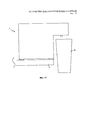
Устройство имеет ножки, расположенные таким образом, чтобы устройство могло частично выступать за край опорной поверхности, например, обеденного стола или кухонной столешницы (нависать над краем). В данном положении подставка для чашки может быть убрана, чтобы вместить контейнеры опускающиеся ниже опорной поверхности непосредственно под носиками.The device has legs arranged in such a way that the device can partially protrude beyond the edge of the supporting surface, for example, a dining table or kitchen worktop (hanging over the edge). In this position, the cup stand can be retracted to accommodate containers falling below the supporting surface directly under the spouts.
Краткое описание чертежейBrief Description of the Drawings
Возможные и предпочтительные признаки настоящего изобретения будут описаны со ссылкой на сопроводительные чертежи. Однако следует понимать, что изображенные и описанные признаки не должны рассматриваться как ограничения объема изобретения. На чертежах представлено следующее:Possible and preferred features of the present invention will be described with reference to the accompanying drawings. However, it should be understood that the features depicted and described should not be construed as limiting the scope of the invention. The drawings show the following:
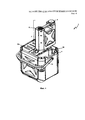
На Фиг. 1 представлено схематическое изображение портативного устройства с системой резервуара для воды, механической системой и системой приготовления напитка (варочной системой).In FIG. 1 is a schematic illustration of a portable device with a water tank system, a mechanical system, and a beverage preparation system (brewing system).
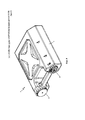
На Фиг. 2 представлено изображение портативного устройства в вертикальном закрытом положении.In FIG. 2 shows an image of a portable device in a vertical closed position.
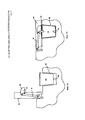
На Фиг. 3 представлено изображение портативного устройства в вертикальном положении, с открытой дверцей системы подачи воды и открытой дверцей системы приготовления показаны и открытой разложенной подставкой.In FIG. Figure 3 shows an image of a portable device in an upright position, with the open door of the water supply system and the open door of the cooking system shown and the open stand unfolded.
На Фиг. 4 изображен резервуар для воды, вынутый из портативного устройства, а также открытая дверца системы резервуара для воды, демонстрирующая отдел для резервуара для воды.In FIG. 4 shows a water tank taken out of a portable device, as well as an open door of a water tank system showing a compartment for a water tank.
На Фиг. 5A представлен вид сбоку подставки в закрытом убранном положении.In FIG. 5A is a side view of a stand in a closed retracted position.
На Фиг. 5B представлен вид сбоку подставки в открытом разложенном положении.In FIG. 5B is a side view of a stand in an open unfolded position.
На Фиг. 6 представлено изображение портативного устройства со снятой подставкой.In FIG. 6 shows an image of a portable device with the stand removed.
На Фиг. 7A изображен колпачок прокалывающего приспособления, находящийся в выдвинутом положении.In FIG. 7A shows a cap of a piercing device in an extended position.
На Фиг. 7B изображен колпачок прокалывающего приспособления, находящийся в отодвинутом положении.In FIG. 7B shows the cap of the piercing device in the retracted position.
На Фиг. 8 представлен подробный вид устройства, хранящегося на боковой стороне.In FIG. 8 is a detailed view of a device stored on the side.
На Фиг. 9 представлен общий вид резервуара для воды, хранящегося на боковой стороне.In FIG. 9 is a perspective view of a water tank stored on a side.
На Фиг. 10 представлен поперечный разрез резервуара для воды.In FIG. 10 is a cross-sectional view of a water tank.
На Фиг. 11 представлен клапан водяной системы, соединяющий резервуар для воды с трубопроводом.In FIG. 11 shows a valve of a water system connecting a water tank to a pipeline.
На Фиг. 12 изображена крышка резервуара для воды.In FIG. 12 shows the lid of a water tank.
На Фиг. 13 представлен поперечный разрез, демонстрирующий частичное нависание устройства над краем опорной поверхности.In FIG. 13 is a cross-sectional view showing a partial overhang of the device over the edge of the abutment surface.
На Фиг. 14 изображена внутренняя опорная рама.In FIG. 14 shows an internal support frame.
Осуществление изобретенияThe implementation of the invention
Как показано на сопроводительных чертежах, портативное устройство 2 по изобретению содержит внешний корпус 1, в котором находится система 38 резервуара для воды, система 39 подачи воды и система 40 приготовления напитка. Электронный блок 14 также размещен внутри внешнего корпуса 1, а пользовательский интерфейс 32 находится на наружной поверхности внешнего корпуса 1.As shown in the accompanying drawings, the
Внутренняя опорная рама 78 расположена под внешним корпусом 1 и обеспечивает опору и защиту для внешнего корпуса 1 устройства 2. Защитная рама 75 окружает пользовательский интерфейс 32, дверцы 42 системы резервуара для воды и дверцы 44 системы приготовления. Защитная рама 75 возвышается над пользовательским интерфейсом 32, дверцей 42 системы резервуара для воды и дверцей 44 системы приготовления таким образом, чтобы данные детали были углублены ниже защитной рамы 75.An
Система 38 резервуара для воды соединена с системой 39 подачи воды, а система 39 подачи воды соединена с системой 40 приготовления напитка. Система 38 резервуара для воды содержит ударопрочный съемный резервуар 3 для воды с крышкой 6 и клапаном 8 водяной системы. Система 39 подачи воды содержит трубопровод 10, расходомер 16, насос 18, нагреватель 20 и регулятор 22 расхода. Система 39 подачи воды управляется с помощью электронного блока 14, который может принимать команды от пользовательского интерфейса 32 и отправлять команды в систему 39 подачи воды для управления работой портативного устройства 2. Система 38 резервуара для воды соединена с системой подачи воды трубопроводом 10, и система 39 подачи воды соединена с системой приготовления трубопроводом 10. Если это затребовано, вода начинает течь по трубопроводу 10 из системы 38 резервуара для воды в систему 39 подачи воды, а затем в систему 40 приготовления напитка.The water tank system 38 is connected to the
Водяной резервуар 3 расположен внутри отдела 4 для водяного резервуара устройства 2. Этот резервуар 3 является съемным, как видно на Фиг. 4 и 9. Резервуар для воды также содержит крышку 6, которая подробно показана на Фиг. 12. Крышка 6 является съемной и сменной, а также содержит уплотнение 7. Уплотнение не позволяет воде вытекать через воздушное отверстие 9. В крышке имеется небольшое воздушное отверстие 9, через которое по мере выхода воды из резервуара 6 поступает воздух. Для наполнения резервуара 3 пользователь должен снять крышку 6. После наполнения резервуара 3 крышку 6 нужно установить на место и закрыть резервуар 3.The
Как показано на Фиг. 10 и 11, трубка 13 расположена внутри резервуара 3 для воды и соединена с клапаном 8 водяной системы. Также между трубкой 13 и клапаном 8 может быть установлен фильтр 12 для воды. Клапан 8 образует выходную точку для воды, когда она затребована для приготовления напитка. Клапан 8 содержит крышку 21, имеющую два уплотнения 17, 19 и пружину 15. Уплотнение 19 закрывает проход в трубку 13 и располагается над пружиной 15. Когда трубопровод 10a соединен с обратным клапаном 8 на уплотнении 19, он нажимает на пружину 15 вниз, позволяя воде выходить. Уплотнение 17 также создает барьер для предотвращения утечки воды.As shown in FIG. 10 and 11, the
Часть трубопровода 10a, соединенная с клапаном 8, расположена внутри дверцы 42 системы резервуара для воды, как показано на Фиг. 3 и 4. Специалистам в данной области техники понятно, что дверца 42 изображена открывающейся на петле 65. Трубопровод 10a выходит из дверцы 42 через соединение 60a в центральную часть устройства. Поскольку трубопровод 10, 10a проходит сквозь дверцу и соединяется с системой 38 резервуара для воды, только когда дверца 42 закрыта, трубопровод 10, 10a должен быть защищен соединением 60a. Когда дверца 42 закрывается, а трубопровод 10a соединен с клапаном 8, что вызывает прижим трубопровода 10a к уплотнению 19, которое в свою очередь вжимается в пружину 15, позволяя воде протекать из трубки 13 в трубопровод 10a. Вода может вытекать из резервуара 3 для воды через клапан 8 в трубопровод 10a только при выдаче соответствующей команды, обеспечивая герметичность системы, защищенной от утечек.A portion of
Для эксплуатации устройства 2 пользователь выбирает нужную функцию с помощью пользовательского интерфейса 32. Это действие посылает сигнал электронному блоку 14, который управляет действиями механической системы 39. Электронный блок 14 и система 39 подачи воды являются ударопрочными, а система подачи воды расположена на раме 41, которая также содержит амортизирующие устройства 62, позволяющие обеспечить дополнительную защиту механической системы от ударов, которые могли бы нарушить работу устройства.To operate the
Для слива воды из резервуара 3 насос 18 выкачивает воду из резервуара 3 через клапан 8 в трубопровод 10. Вода проходит по трубопроводу 10 и ее количество измеряется расходомером 16. Расходомер 16 контролирует количество воды, которая должна быть втянута из резервуара 3. Затем вода прокачивается через нагреватель 20 насосом 18. После того как вода нагрета, она направляется от регулятора расхода 22 либо для приготовления напитка, либо для выдачи в виде горячей воды. Таким образом, вода направляется либо в водяную линию 10c, через которую разливается горячая вода, либо в линию 10b для напитка, через которую разливается напиток.To drain water from the
Если пользователь хочет налить горячую воду, то вода направляется от регулятора расхода 22 по водяной линии 10c в водяной носик 30 и в чашку 50, которая может быть размещена на подставке 36. Водяной носик 30 и носик 28 для подачи напитка представляют собой отдельные компоненты, благодаря чему пользователь может быть уверен, что наливает чистую воду.If the user wants to pour hot water, the water is sent from the
Если нужно приготовить напиток, то вода протекает от регулятора расхода 22 по линии 10b подачи напитка в систему 40 приготовления.If a beverage is to be prepared, water flows from the
Когда пользователь хочет использовать изделие для приготовления напитка, он нажимает на соответствующую кнопку на интерфейсе 32. Система 40 приготовления содержит камеру заваривания 48, по меньшей мере один носик (форсунку) 28 и прокалывающие иглы 24. Капсулу 26 помещают в систему 40 приготовления, в частности, в камеру заваривания 48. Предполагается, что камера заваривания 48 работает в закрытом положении, а для получения доступа в камеру 48 необходимо открыть дверцу 44. Действие, закрывающее дверцу 44, толкает капсулу 26 вниз, накалывая ее на выходную иглу 49 в нижней части камеры заваривания 48. В точке, где выходная игла 49 протыкает капсулу 26, образуется выходное отверстие, через которое готовый напиток может выйти из капсулы 26. Камера заваривания 26 также содержит входную иглу 24, расположенную в дверце 44. Входная игла 24 может проткнуть верхнюю часть капсулы 26, создавая входное отверстие, открывающее путь в капсулу 26 из регулятора расхода 22.When the user wants to use the product to prepare a drink, he clicks on the corresponding button on the
Входная игла 24 закрыта подвижным колпачком 46, изображенным на Фиг. 7A и 7B. Колпачок 46 перемещается с помощью исполнительного механизма 70. Дверца 44 системы приготовления имеет открытое и закрытое положения. Как показано на Фиг. 7A, когда дверца 44 находится в открытом положении, колпачок 46 закрывает иглу 24. Когда дверца 44 поворачивается в закрытое положение, исполнительный механизм 70 перемещает колпачок 46 в отодвинутое положение и освобождает иглу 24, чтобы она могла проколоть капсулу 26.The
Когда капсула находится на месте внутри камеры заваривания 48, в ней может быть заварен напиток по мере поступления воды в капсулу 26. Нагретая вода протекает от регулятора расхода 22 через трубопровод 10 и иглу 24 в капсулу 26. Напиток варится внутри капсулы 26 и вытекает из капсулы 26 через выходное отверстие к носику 28 подачи напитка. Затем готовый напиток вытекает из носика 28 в чашку 50, размещенную на подставке 36.When the capsule is in place inside the
На Фиг. 5A и 5B показано, что подставку 36 можно складывать внутрь и раскладывать наружу из устройства 2. Подставка 36 также является съемной, как показано на Фиг. 6. На Фиг. 13 представлено изображение устройства 2, с которого снята подставка 36, а чашка 50 нависает относительно опорной поверхности 76.In FIG. 5A and 5B show that the
Устройство оборудовано предохранительным датчиком 58. Этот датчик определяет, открыл ли пользователь камеру заваривания во время приготовления горячего напитка. При открывании дверцы 44 системы приготовления во время накачивания горячей воды или оставшегося пара из регулятора расхода 22 в систему 40 приготовления, предохранительный датчик 58 перекрывает поток воды и переключает клапан так, чтобы вместо этого направить воду в водяную линию 10c и вывести ее через водяной носик 30 в стороне от пользователя.The device is equipped with a safety sensor 58. This sensor determines whether the user opened the brewing chamber during the preparation of a hot drink. When the
В контексте настоящего описания и формулы изобретения термин «содержит» и его производные предполагаются имеющими значение «включает в себя», а не «представляет собой», если явно не указано иное или если иное не следует из контекста. Другими словами, термин «содержит» и его производные предназначены для обозначения наличия не только тех компонентов, этапов или признаков, которые явно указаны, но и других не перечисленных компонентов, этапов или признаков, если явно не указано иное или если иное не следует из контекста.In the context of the present description and claims, the term “comprises” and its derivatives are intended to have the meaning “includes” rather than “represents” unless expressly indicated otherwise or unless otherwise indicated by context. In other words, the term “contains” and its derivatives are intended to mean the presence of not only those components, steps or features that are explicitly indicated, but also other components, steps or features not listed, unless otherwise specified or unless otherwise indicated by the context .
Специалистам в данной области техники понятно, что описанные способы по изобретению могут быть изменены и модифицированы различным образом без выхода за рамки сущности и объема изобретения.Those skilled in the art will appreciate that the described methods of the invention can be modified and modified in various ways without departing from the spirit and scope of the invention.
Claims (31)
Applications Claiming Priority (3)
| Application Number | Priority Date | Filing Date | Title |
|---|---|---|---|
| US201361810781P | 2013-04-11 | 2013-04-11 | |
| US61/810,781 | 2013-04-11 | ||
| PCT/US2014/033864 WO2014169248A1 (en) | 2013-04-11 | 2014-04-11 | Portable coffee brewer |
Related Child Applications (1)
| Application Number | Title | Priority Date | Filing Date |
|---|---|---|---|
| RU2018115552A Division RU2018115552A (en) | 2013-04-11 | 2014-04-11 | PUNCTURE DEVICE FOR BEVERAGE CAPSULE |
Publications (2)
| Publication Number | Publication Date |
|---|---|
| RU2015146862A RU2015146862A (en) | 2017-05-12 |
| RU2657227C2 true RU2657227C2 (en) | 2018-06-08 |
Family
ID=51690045
Family Applications (2)
| Application Number | Title | Priority Date | Filing Date |
|---|---|---|---|
| RU2018115552A RU2018115552A (en) | 2013-04-11 | 2014-04-11 | PUNCTURE DEVICE FOR BEVERAGE CAPSULE |
| RU2015146862A RU2657227C2 (en) | 2013-04-11 | 2014-04-11 | Beverage preparation device |
Family Applications Before (1)
| Application Number | Title | Priority Date | Filing Date |
|---|---|---|---|
| RU2018115552A RU2018115552A (en) | 2013-04-11 | 2014-04-11 | PUNCTURE DEVICE FOR BEVERAGE CAPSULE |
Country Status (10)
| Country | Link |
|---|---|
| US (1) | US11083330B2 (en) |
| EP (1) | EP2983570B1 (en) |
| JP (2) | JP6416211B2 (en) |
| KR (1) | KR20160005706A (en) |
| CN (1) | CN105263372A (en) |
| BR (1) | BR112015025997A2 (en) |
| CA (1) | CA2909352A1 (en) |
| MX (1) | MX2015014263A (en) |
| RU (2) | RU2018115552A (en) |
| WO (1) | WO2014169248A1 (en) |
Families Citing this family (12)
| Publication number | Priority date | Publication date | Assignee | Title |
|---|---|---|---|---|
| US9687105B2 (en) | 2013-09-06 | 2017-06-27 | Big Spoon Productions, Llc | Insulated multifunctional portable beverage brewing device |
| US20160348046A1 (en) * | 2014-01-29 | 2016-12-01 | Williamswarn Holdings Limited. | Brewing apparatus and method of use |
| KR101641879B1 (en) * | 2015-05-21 | 2016-07-29 | (주)애니토이 | clean box apparatus for extraction of dutch coffee |
| BR112019008836A2 (en) | 2016-11-09 | 2019-07-09 | Pepsico Inc | carbonated beverage manufacturing sets, methods, and systems |
| US11470998B2 (en) * | 2017-01-10 | 2022-10-18 | Nuwave, Llc | Automatic beverage maker reservoir heating system |
| CN107928408A (en) * | 2017-10-13 | 2018-04-20 | 青岛海尔股份有限公司 | Refrigerator |
| CN107744339A (en) | 2017-10-13 | 2018-03-02 | 青岛海尔股份有限公司 | Refrigerator |
| CN109820421A (en) * | 2017-11-23 | 2019-05-31 | 德隆奇电器单一股东有限责任公司 | It is used to prepare the machine and its control method of beverage |
| CN109316064B (en) * | 2018-11-30 | 2023-11-10 | 深圳市西啡科技有限公司 | Beverage preparation device |
| US11553814B2 (en) | 2019-08-28 | 2023-01-17 | Ii-Vi Delaware, Inc. | Non-electric powered, off-grid, beverage brewer |
| US11607071B1 (en) | 2020-03-10 | 2023-03-21 | Walter Negron | Portable coffee brewer |
| US11337545B1 (en) * | 2021-12-14 | 2022-05-24 | Cana Technology, Inc. | Fluid mixture dispensing device |
Citations (4)
| Publication number | Priority date | Publication date | Assignee | Title |
|---|---|---|---|---|
| DE2907495A1 (en) * | 1979-02-26 | 1980-09-04 | Willi Naumann | Portable hot water serving equipment - comprises rectangular tank for water heated by electric coils from mains or LV supply and dispensing lever arm leading to drinking cup |
| US6701826B2 (en) * | 2002-06-28 | 2004-03-09 | Eupa International Corporation | Electric coffee maker for selectively brewing Espresso coffee and Americano coffee |
| US20050199130A1 (en) * | 2004-02-23 | 2005-09-15 | Pragotrade Usa, Incorporated | Portable coffee maker |
| CN202674445U (en) * | 2012-06-04 | 2013-01-16 | 王胜章 | Pressurized aeration valve device for drink can |
Family Cites Families (30)
| Publication number | Priority date | Publication date | Assignee | Title |
|---|---|---|---|---|
| US3083450A (en) * | 1959-12-10 | 1963-04-02 | Louis A Harvey | Portable cooking appliance |
| US3813517A (en) * | 1973-01-04 | 1974-05-28 | I Mcgruder | Battery operated coffee maker |
| DE2750800C3 (en) | 1977-11-14 | 1981-05-07 | Bosch-Siemens Hausgeräte GmbH, 7000 Stuttgart | Electric coffee maker |
| US4286636A (en) * | 1979-07-19 | 1981-09-01 | The Coca-Cola Company | Dip tube and valve with quick-disconnect coupling for a collapsible container |
| DE3404320A1 (en) * | 1983-03-23 | 1984-09-27 | Alfonso Bialetti & C. S.p.A., Omegna-Crusinallo, Novara | DEVICE DETERMINED FOR HOUSEHOLD USE FOR THE PRODUCTION OF WARM BEVERAGES AND RELATED COFFEE MAKERS |
| JPS61164527A (en) | 1985-01-17 | 1986-07-25 | 株式会社東芝 | Coffee extractor |
| IT1235261B (en) | 1989-01-30 | 1992-06-26 | Illycaffe Spa | COFFEE MACHINE'. |
| US5154317A (en) * | 1990-07-09 | 1992-10-13 | Roppolo Iii Michael A | Portable liquid dispenser |
| US6082247A (en) * | 1999-01-19 | 2000-07-04 | Keurig, Inc. | Apparatus for consecutively dispensing an equal volume of liquid |
| NL1012847C2 (en) * | 1999-08-17 | 2001-02-20 | Sara Lee De Nv | Coffee preparation device. |
| US6357342B1 (en) * | 2000-09-11 | 2002-03-19 | Simatelex Manufactory Co., Ltd. | Electric coffee maker |
| DE60113402T2 (en) | 2001-07-20 | 2006-06-22 | Société des Produits Nestlé S.A. | Coffee machine for an automobile |
| US6619507B2 (en) * | 2001-08-16 | 2003-09-16 | Food Equipment Technologies Company, Inc. | Beverage dispenser with drip tray assembly and method |
| WO2003030696A1 (en) * | 2001-10-05 | 2003-04-17 | Hp Intellectual Corp. | Coffee maker |
| FR2842089B1 (en) * | 2002-07-12 | 2004-12-24 | Seb Sa | COFFEE MACHINE COMPRISING AN IMPROVED DEVICE FOR PERFORATING DOSES |
| US7401546B2 (en) * | 2003-09-09 | 2008-07-22 | Dairy Tech, Inc. | Batch pasteurizer |
| US20050150824A1 (en) * | 2004-01-08 | 2005-07-14 | Kaz, Incorporated | Water filtration tank dispensing system |
| GB2411105B (en) * | 2004-02-17 | 2006-08-30 | Kraft Foods R & D Inc | An insert and a system for the preparation of beverages |
| ITFI20040121A1 (en) * | 2004-05-28 | 2004-08-28 | Bialetti Ind Spa | ELECTRIC COFFEE SHOP FOR THE PRODUCTION OF ESPRESSO COFFEE |
| DE102004056317A1 (en) * | 2004-11-22 | 2006-05-24 | Schifferle, René | Beverage machine for producing a hot beverage by brewing and extracting substances packaged in a capsule |
| US9795243B2 (en) * | 2005-05-23 | 2017-10-24 | Adrian Rivera | Single serving brewing material holder |
| ATE498340T1 (en) * | 2006-06-09 | 2011-03-15 | Nestec Sa | MODULAR DRINK MAKING SYSTEM WITH A DOCKING STATION |
| DE102006060746B3 (en) * | 2006-12-21 | 2008-01-31 | BSH Bosch und Siemens Hausgeräte GmbH | Beverage brewing machine has brewing chamber which is opened for loading with beverage substrate portions, and safety valve prevents water supply into open brewing chamber |
| PT2243405E (en) | 2007-06-05 | 2012-12-06 | Criali Invest Sa | Capsule for preparing a drink and method for preparing a drink using such capsule |
| ATE525943T1 (en) | 2007-08-29 | 2011-10-15 | Nestec Sa | DISPENSING DEVICE FOR PREPARING AND DISPENSING A FOOD AND/OR A NUTRITIONAL COMPOSITION |
| US20110239869A1 (en) * | 2007-11-09 | 2011-10-06 | Herbst Andrew F | Method, system and apparatus for housing and dispensing liquid |
| EP2070454B1 (en) | 2007-12-12 | 2015-07-15 | Nestec S.A. | Beverage production machines comprising a plurality of core units |
| US8360279B1 (en) * | 2008-11-26 | 2013-01-29 | Giles Matthew L | Automatic baby formula preparation device |
| BR112012011161A8 (en) * | 2009-11-12 | 2019-02-12 | Formulanow Llc | punching, cartridge and mixing equipment and method for combining mixing and liquid |
| CN103458746B (en) | 2010-11-12 | 2016-12-28 | 洛伦佐·贾科明 | The machine driven for the exchange and/or low dc voltage of preparing espresso or beverage brewed |
-
2014
- 2014-04-11 WO PCT/US2014/033864 patent/WO2014169248A1/en active Application Filing
- 2014-04-11 RU RU2018115552A patent/RU2018115552A/en not_active Application Discontinuation
- 2014-04-11 BR BR112015025997A patent/BR112015025997A2/en not_active IP Right Cessation
- 2014-04-11 CA CA2909352A patent/CA2909352A1/en not_active Abandoned
- 2014-04-11 US US14/783,607 patent/US11083330B2/en active Active
- 2014-04-11 EP EP14782744.8A patent/EP2983570B1/en active Active
- 2014-04-11 MX MX2015014263A patent/MX2015014263A/en unknown
- 2014-04-11 JP JP2016507693A patent/JP6416211B2/en not_active Expired - Fee Related
- 2014-04-11 RU RU2015146862A patent/RU2657227C2/en not_active IP Right Cessation
- 2014-04-11 KR KR1020157032342A patent/KR20160005706A/en not_active Application Discontinuation
- 2014-04-11 CN CN201480028704.8A patent/CN105263372A/en active Pending
-
2018
- 2018-04-05 JP JP2018073418A patent/JP2018118121A/en active Pending
Patent Citations (4)
| Publication number | Priority date | Publication date | Assignee | Title |
|---|---|---|---|---|
| DE2907495A1 (en) * | 1979-02-26 | 1980-09-04 | Willi Naumann | Portable hot water serving equipment - comprises rectangular tank for water heated by electric coils from mains or LV supply and dispensing lever arm leading to drinking cup |
| US6701826B2 (en) * | 2002-06-28 | 2004-03-09 | Eupa International Corporation | Electric coffee maker for selectively brewing Espresso coffee and Americano coffee |
| US20050199130A1 (en) * | 2004-02-23 | 2005-09-15 | Pragotrade Usa, Incorporated | Portable coffee maker |
| CN202674445U (en) * | 2012-06-04 | 2013-01-16 | 王胜章 | Pressurized aeration valve device for drink can |
Also Published As
| Publication number | Publication date |
|---|---|
| EP2983570A4 (en) | 2017-06-14 |
| KR20160005706A (en) | 2016-01-15 |
| BR112015025997A2 (en) | 2017-07-25 |
| CN105263372A (en) | 2016-01-20 |
| RU2018115552A (en) | 2019-03-05 |
| CA2909352A1 (en) | 2014-10-16 |
| JP2016518906A (en) | 2016-06-30 |
| RU2015146862A (en) | 2017-05-12 |
| MX2015014263A (en) | 2017-06-08 |
| EP2983570B1 (en) | 2019-07-17 |
| US20160058242A1 (en) | 2016-03-03 |
| WO2014169248A1 (en) | 2014-10-16 |
| JP2018118121A (en) | 2018-08-02 |
| EP2983570A1 (en) | 2016-02-17 |
| US11083330B2 (en) | 2021-08-10 |
| JP6416211B2 (en) | 2018-10-31 |
Similar Documents
| Publication | Publication Date | Title |
|---|---|---|
| RU2657227C2 (en) | Beverage preparation device | |
| RU2488337C2 (en) | Liquid food or beverages preparation machine to be carried over with one hand | |
| RU2520600C2 (en) | Modular system with standalone module having small resting surface | |
| CN204071714U (en) | For the thermal control equipment of liquid heater, 360 ° of wireless electrical connection systems and utensil | |
| EP3166456B1 (en) | Accessory for supplying automatically a beverage machine with liquid from a distribution network | |
| EP3166457B1 (en) | Device for connecting a beverage machine to a distribution network with safe monitoring | |
| US10455975B2 (en) | Beverage preparation machine | |
| CA2616716C (en) | Beverage brewing devices having moveable reservoirs | |
| US6708598B2 (en) | Beverage dispenser with cover assembly and method | |
| EP3643213B1 (en) | Automatic coffee machine | |
| JP2004215764A (en) | Coffee brewer |
Legal Events
| Date | Code | Title | Description |
|---|---|---|---|
| HZ9A | Changing address for correspondence with an applicant | ||
| MM4A | The patent is invalid due to non-payment of fees |
Effective date: 20200412 |