RU2651881C2 - Skin treatment device - Google Patents
Skin treatment device Download PDFInfo
- Publication number
- RU2651881C2 RU2651881C2 RU2015110514A RU2015110514A RU2651881C2 RU 2651881 C2 RU2651881 C2 RU 2651881C2 RU 2015110514 A RU2015110514 A RU 2015110514A RU 2015110514 A RU2015110514 A RU 2015110514A RU 2651881 C2 RU2651881 C2 RU 2651881C2
- Authority
- RU
- Russia
- Prior art keywords
- wheel
- skin
- angular position
- faces
- light
- Prior art date
Links
Images


Classifications
-
- A—HUMAN NECESSITIES
- A61—MEDICAL OR VETERINARY SCIENCE; HYGIENE
- A61B—DIAGNOSIS; SURGERY; IDENTIFICATION
- A61B18/00—Surgical instruments, devices or methods for transferring non-mechanical forms of energy to or from the body
- A61B18/18—Surgical instruments, devices or methods for transferring non-mechanical forms of energy to or from the body by applying electromagnetic radiation, e.g. microwaves
- A61B18/20—Surgical instruments, devices or methods for transferring non-mechanical forms of energy to or from the body by applying electromagnetic radiation, e.g. microwaves using laser
- A61B18/203—Surgical instruments, devices or methods for transferring non-mechanical forms of energy to or from the body by applying electromagnetic radiation, e.g. microwaves using laser applying laser energy to the outside of the body
-
- G—PHYSICS
- G02—OPTICS
- G02B—OPTICAL ELEMENTS, SYSTEMS OR APPARATUS
- G02B26/00—Optical devices or arrangements for the control of light using movable or deformable optical elements
- G02B26/08—Optical devices or arrangements for the control of light using movable or deformable optical elements for controlling the direction of light
- G02B26/10—Scanning systems
- G02B26/12—Scanning systems using multifaceted mirrors
-
- A—HUMAN NECESSITIES
- A61—MEDICAL OR VETERINARY SCIENCE; HYGIENE
- A61B—DIAGNOSIS; SURGERY; IDENTIFICATION
- A61B18/00—Surgical instruments, devices or methods for transferring non-mechanical forms of energy to or from the body
- A61B2018/00315—Surgical instruments, devices or methods for transferring non-mechanical forms of energy to or from the body for treatment of particular body parts
- A61B2018/00452—Skin
- A61B2018/0047—Upper parts of the skin, e.g. skin peeling or treatment of wrinkles
-
- A—HUMAN NECESSITIES
- A61—MEDICAL OR VETERINARY SCIENCE; HYGIENE
- A61B—DIAGNOSIS; SURGERY; IDENTIFICATION
- A61B18/00—Surgical instruments, devices or methods for transferring non-mechanical forms of energy to or from the body
- A61B2018/00636—Sensing and controlling the application of energy
- A61B2018/00773—Sensed parameters
- A61B2018/00779—Power or energy
-
- A—HUMAN NECESSITIES
- A61—MEDICAL OR VETERINARY SCIENCE; HYGIENE
- A61B—DIAGNOSIS; SURGERY; IDENTIFICATION
- A61B18/00—Surgical instruments, devices or methods for transferring non-mechanical forms of energy to or from the body
- A61B18/18—Surgical instruments, devices or methods for transferring non-mechanical forms of energy to or from the body by applying electromagnetic radiation, e.g. microwaves
- A61B18/20—Surgical instruments, devices or methods for transferring non-mechanical forms of energy to or from the body by applying electromagnetic radiation, e.g. microwaves using laser
- A61B2018/2035—Beam shaping or redirecting; Optical components therefor
- A61B2018/20351—Scanning mechanisms
- A61B2018/20355—Special scanning path or conditions, e.g. spiral, raster or providing spot overlap
-
- A—HUMAN NECESSITIES
- A61—MEDICAL OR VETERINARY SCIENCE; HYGIENE
- A61B—DIAGNOSIS; SURGERY; IDENTIFICATION
- A61B18/00—Surgical instruments, devices or methods for transferring non-mechanical forms of energy to or from the body
- A61B18/18—Surgical instruments, devices or methods for transferring non-mechanical forms of energy to or from the body by applying electromagnetic radiation, e.g. microwaves
- A61B18/20—Surgical instruments, devices or methods for transferring non-mechanical forms of energy to or from the body by applying electromagnetic radiation, e.g. microwaves using laser
- A61B2018/2035—Beam shaping or redirecting; Optical components therefor
- A61B2018/205547—Controller with specific architecture or programmatic algorithm for directing scan path, spot size or shape, or spot intensity, fluence or irradiance
Landscapes
- Physics & Mathematics (AREA)
- Health & Medical Sciences (AREA)
- Optics & Photonics (AREA)
- Surgery (AREA)
- Life Sciences & Earth Sciences (AREA)
- Heart & Thoracic Surgery (AREA)
- Molecular Biology (AREA)
- Nuclear Medicine, Radiotherapy & Molecular Imaging (AREA)
- Engineering & Computer Science (AREA)
- Biomedical Technology (AREA)
- Electromagnetism (AREA)
- Medical Informatics (AREA)
- Otolaryngology (AREA)
- Animal Behavior & Ethology (AREA)
- General Health & Medical Sciences (AREA)
- Public Health (AREA)
- Veterinary Medicine (AREA)
- General Physics & Mathematics (AREA)
- Radiation-Therapy Devices (AREA)
- Measuring And Recording Apparatus For Diagnosis (AREA)
- Laser Surgery Devices (AREA)
Abstract
Description
Область техники, к которой относится изобретениеFIELD OF THE INVENTION
Настоящее изобретение относятся к устройству для ухода за кожей, содержащему источник света, обеспечивающий световой луч для оптической обработки кожи, колесико с поверхностью колесика для отражения светового луча по направлению к коже, приводное средство для поворота колесика для изменения углового положения колесика, причем разные угловые положения колесика отвечают соответствующим разным направлениям отражения светового луча, и схему управления для управления источником света.The present invention relates to a skin care device comprising a light source providing a light beam for optically treating the skin, a wheel with a surface of a wheel for reflecting a light beam towards the skin, a driving means for turning the wheel to change the angular position of the wheel, different angular positions the wheels correspond to respective different directions of reflection of the light beam, and a control circuit for controlling the light source.
Уровень техники по изобретениюBACKGROUND OF THE INVENTION
Такое устройство для ухода за кожей описано, например, в заявке на патент США, опубликованной как US 2012/0197357 A1. Упомянутое устройство для ухода за кожей содержит лазерный источник и оптический генератор шаблонных изображений (далее - шаблонов) для создания микроскопических зон обработки (зон MTZ - microscopic treatment zone) термически денатурированной кожной ткани, окруженной незатронутой кожной тканью. Такая обработка стимулирует механизмы восстановления кожи и улучшает внешний вид кожи. Аксиконическое колесико с множеством аксиконических сегментов отклоняет лазерный луч по направлению к соответствующему множеству разных участков поверхности кожи. Схема управления управляет лазерным источником, чтобы в произвольном порядке освещать отдельные аксиконические сегменты. Когда пользователь медленно перемещает устройство вдоль поверхности кожи, произвольно выбранный шаблон зон MTZ применяется к поверхности кожи. Уровень интенсивности, установленный пользователем, определяет плотность произвольно выбранного шаблона.Such a skin care device is described, for example, in US patent application published as US 2012/0197357 A1. The said skin care device contains a laser source and an optical template image generator (hereinafter referred to as templates) for creating microscopic treatment zones (MTZ zones) of thermally denatured skin tissue surrounded by unaffected skin tissue. This treatment stimulates skin repair mechanisms and improves the appearance of the skin. An axiconic wheel with many axiconic segments deflects the laser beam towards the corresponding many different parts of the skin surface. The control circuit controls the laser source to randomly illuminate individual axiconic segments. When the user slowly moves the device along the skin surface, an arbitrarily selected MTZ zone pattern is applied to the skin surface. The intensity level set by the user determines the density of a randomly selected pattern.
В известном устройстве каждая асиконическая грань имеет пусковой лепесток, который обнаруживается датчиком обнаружения лепестков при прохождении его мимо датчика обнаружения лепестков во время поворота аксиконического колесика. Датчик обнаружения лепестков соединен со схемой управления, которая определяет скорость поворота аксиконического колесика, основываясь на сигнале датчика обнаружения лепестков. Исходя из скорости поворота аксиконического колесика и измеренной скорости, с которой пользователь перемещает устройство вдоль поверхности кожи, схема управления способна обеспечивать распределенные в случайном порядке зоны MTZ с более или менее постоянной плотностью.In the known device, each asiconic face has a start lobe, which is detected by the lobe detection sensor when it passes by the lobe detection sensor while the axicon wheel is turning. The petal detection sensor is connected to a control circuit that detects the rotation speed of the axiconic wheel based on the signal of the petal detection sensor. Based on the speed of rotation of the axiconic wheel and the measured speed at which the user moves the device along the skin surface, the control circuit is able to provide randomly distributed MTZ zones with a more or less constant density.
Хотя возможность устанавливать уровень интенсивности обеспечивает определенный контроль над работой устройства, по-прежнему существует необходимость в улучшении управления обработкой, чтобы лучше приспособиться к отличиям в типе кожи, состоянии кожи, обработке кожи и предпочтениям пользователя. Может, например, оказаться желательным сделать работу устройства более приспособленной к определенным признакам кожи, таким как складки, тонкие и мелкие морщинки и пигментные пятна.Although the ability to set the level of intensity provides some control over the operation of the device, there is still a need to improve processing control in order to better adapt to differences in skin type, skin condition, skin treatment and user preferences. It may, for example, be desirable to make the device more adapted to certain skin features, such as wrinkles, fine and fine wrinkles, and age spots.
Задача изобретенияObject of the invention
Задачей настоящего изобретения является обеспечение устройства для ухода за кожей такого типа, как указано во вступительном параграфе, обладающего улучшенным управлением при осуществлении ухода за кожей.It is an object of the present invention to provide a skin care device of the type described in the introductory paragraph, which has improved control in performing skin care.
Сущность изобретенияSUMMARY OF THE INVENTION
Согласно первому аспекту изобретения эта задача решается обеспечением устройства для ухода за кожей, которое содержит источник света для образования светового луча для оптической обработки кожи, колесико с поверхностью колесика для отражения светового луча по направлению к коже, приводное средство для поворота колесика для изменения углового положения колесика, при этом разные угловые положения колесика отвечают соответствующим разным направлениям отражения светового луча, датчик углового положения для обнаружения углового положения колесика или параметра, соответствующего упомянутому угловому положению, средство памяти для хранения заданного шаблона обработки кожи и соотношения между разными угловыми положениями колесика или параметром, соответствующим упомянутому угловому положению, и соответствующими связанными с ними разными направлениями отражения светового луча или параметра, соответствующего упомянутому направлению отражения, и схему управления, соединенную с источником света, датчиком углового положения и средством памяти и используемую для управления источником света в зависимости от углового положения, обнаруженного датчиком углового положения, таким образом, что при каждом обороте колесика световой луч освещает только поверхность колесика в выбранных угловых положениях колесика для реализации заданного шаблона обработки кожи.According to a first aspect of the invention, this object is achieved by providing a skin care device that comprises a light source for generating a light beam for optically treating the skin, a wheel with a surface of the wheel for reflecting the light beam towards the skin, and driving means for rotating the wheel for changing the angular position of the wheel while the different angular positions of the wheel correspond to the corresponding different directions of reflection of the light beam, the angle sensor for detecting the angular position ia a wheel or a parameter corresponding to said angular position, memory means for storing a predetermined skin processing pattern and a relation between different angular positions of a wheel or a parameter corresponding to said angular position and corresponding different reflection directions of a light beam or a parameter corresponding to said reflection direction and a control circuitry connected to the light source, the angle sensor and the memory means and used to control the light source depending on the angular position detected by the angular position sensor, so that at each revolution of the wheel, the light beam illuminates only the surface of the wheel in the selected angular positions of the wheel to implement a given skin processing pattern.
В устройстве для ухода за кожей согласно US 2012/0197357 A1 обработка всегда начинается при нахождении аксиконического колесика в случайном и неизвестном положении. Затем источник света в произвольном порядке освещает неизвестные грани аксиконического колесика, что приводит в результате к образованию зон MTZ в случайных положениях на коже. Для известного устройства это в действительности не считается проблемой, поскольку при каждом обороте колесика все грани имеют равную возможность быть освещенными и общим результатом является равномерное распределение зон MTZ с желаемой плотностью.In a skin care device according to US 2012/0197357 A1, treatment always starts when the axiconic wheel is in a random and unknown position. Then, the light source randomly illuminates the unknown edges of the axiconical wheel, which results in the formation of MTZ zones in random positions on the skin. For a known device, this is not really considered a problem, since with each revolution of the wheel all faces have an equal opportunity to be illuminated and the overall result is a uniform distribution of MTZ zones with the desired density.
В устройстве согласно изобретению возможно начинать обработку с выбранного углового положения колесика и соответствующего направления отражения светового луча или, в общем случае, возможно обеспечивать зоны MTZ в соответствии с заданным шаблоном на коже, отражая световой луч в выбранной последовательности направлений отражения, соответствующих заданному шаблону обработки кожи. Поскольку направления отражения, соответствующие заданным угловым положением колесика, фиксированы, знание углового положения колесика, полученное благодаря датчику углового положения, позволяет мгновенно узнавать направление, в котором отражается свет от источника света. Например, схема управления может управлять источником света, чтобы освещать поверхность колесика только во время первой или второй половины каждого оборота колесика. Сочетание знания углового положения с сохраненными соответствующими направлениями отражения позволяет схеме управления создавать зоны MTZ только в выбранных положениях на коже в соответствии с заданным шаблоном обработки кожи, которые могут, например, быть выбраны пользователем. При перемещении устройства вдоль кожи появляется шаблон обработки кожи с зонами MTZ в предварительно выбранных местах на коже вместо случайно выбираемого шаблона, генерируемого известным устройством. Шаблон обработки кожи может содержать, например, прямые вертикальные, горизонтальные или диагональные линии зон MTZ. Могут также генерироваться колеблющиеся шаблоны MTZ или отдельные пятна зон MTZ разных форм.In the device according to the invention, it is possible to start processing from the selected angular position of the wheel and the corresponding direction of reflection of the light beam, or, in general, it is possible to provide MTZ zones in accordance with a given pattern on the skin, reflecting the light beam in a selected sequence of reflection directions corresponding to a given pattern of skin processing . Since the reflection directions corresponding to the given angular position of the wheel are fixed, the knowledge of the angular position of the wheel, obtained thanks to the angular position sensor, allows you to instantly recognize the direction in which light is reflected from the light source. For example, a control circuit may control a light source to illuminate the surface of the wheel only during the first or second half of each revolution of the wheel. The combination of knowledge of the angular position with the corresponding reflection directions saved allows the control circuit to create MTZ zones only at selected positions on the skin in accordance with a specified skin processing pattern, which can, for example, be selected by the user. When you move the device along the skin, a skin processing pattern appears with MTZ zones in pre-selected locations on the skin instead of a randomly selected pattern generated by the known device. The skin treatment template may comprise, for example, straight vertical, horizontal or diagonal lines of MTZ zones. Oscillating MTZ patterns or single spots of MTZ zones of different shapes can also be generated.
В предпочтительном варианте реализации датчик углового положения расположен так, чтобы обнаруживать прохождение идентификационного элемента, связанного с заданным одним из разных угловых положений колесика. Идентификационный элемент может быть частью самой поверхности колесика, элементом, прикрепленным к поверхности колесика в определенной позиции, или просто элементом, выполненным на колесике в некоторой заданной позиции. Конечно, в дополнение к первому идентификационному элементу может также обнаруживаться прохождение второго или даже нескольких уникальных идентификационных элементов, причем каждый уникальный идентификационный элемент соответствует разному угловому положению. Однако в общем случае изобретение может быть использовано с любым видом датчика углового положения для обнаружения углового положения колесика или с любым видом датчика для обнаружения параметра, соответствующего угловому положению.In a preferred embodiment, the angular position sensor is positioned to detect the passage of an identification element associated with a predetermined one of the different angular positions of the wheel. The identification element may be part of the surface of the wheel itself, an element attached to the surface of the wheel in a specific position, or simply an element made on the wheel in some predetermined position. Of course, in addition to the first identification element, the passage of a second or even several unique identification elements can also be detected, each unique identification element corresponding to a different angular position. However, in the General case, the invention can be used with any type of angle sensor for detecting the angular position of the wheel or with any type of sensor for detecting a parameter corresponding to the angular position.
В предпочтительном варианте осуществления поверхность колесика содержит множество граней для отражения светового луча в сторону кожи во взаимно отличающихся направлениях отражения, причем каждая грань соответствует одному из разных направлений отражения. В другом варианте осуществления идентификационный элемент связан с заданной одной из множества граней. Примером подходящего колесика является аксиконическое колесико. Следует, однако, заметить, что изобретение вовсе не ограничивается использованием многогранных колесиков или аксиконических колесиков. Например, колесико, в котором направление отражения изменяется постепенно вдоль окружности, может быть использовано подобным образом и с подобным полезным эффектом. По существу посредством дальнейшего увеличения числа граней и уменьшения отличия в ориентации между последовательными гранями достигается приближенное представление такого колесика с постепенным и постоянным изменением направления отражения вдоль окружности.In a preferred embodiment, the surface of the wheel comprises a plurality of faces for reflecting the light beam towards the skin in mutually different directions of reflection, each face corresponding to one of different directions of reflection. In another embodiment, the identification element is associated with a given one of the many faces. An example of a suitable wheel is an axiconical wheel. However, it should be noted that the invention is not at all limited to the use of polyhedral wheels or axiconic wheels. For example, a wheel in which the direction of reflection changes gradually along a circle can be used in a similar manner and with a similar beneficial effect. Essentially, by further increasing the number of faces and reducing the difference in orientation between successive faces, an approximate representation of such a wheel is achieved with a gradual and constant change in the direction of reflection along the circle.
Согласно изобретению средство памяти используется для хранения отношения между разными угловыми положениями колесика и соответствующими, связанными с ними направлениями отражения светового луча или параметра, соответствующего упомянутым направлениям отражения. Вместо углового положения любой параметр, соответствующий упомянутому угловому положению, может быть использован средством памяти. Вместо направления отражения любой параметр, соответствующий упомянутому направлению отражения, может быть использован средством памяти. В приводимом в качестве примера варианте осуществления средство памяти используется для сохранения последовательности множества граней, и схема управления выполнена с возможностью избирательного освещения граней, основываясь на сохраненной последовательности множества граней и прохождении заданной одной из множества граней. В этом варианте осуществления параметр, соответствующий направлению отражения, является порядковым номером граней, и мониторинг углового положения осуществляется на основе прохождения заданной одной из множества граней и скорости поворота колесика.According to the invention, a memory means is used for storing the relationship between the different angular positions of the wheel and the respective associated directions of reflection of the light beam or a parameter corresponding to the mentioned directions of reflection. Instead of the angular position, any parameter corresponding to the said angular position can be used by the memory means. Instead of a direction of reflection, any parameter corresponding to said direction of reflection can be used by a memory means. In an exemplary embodiment, a memory means is used to store a sequence of multiple faces, and the control circuit is configured to selectively illuminate faces based on a stored sequence of multiple faces and passing a predetermined one of the multiple faces. In this embodiment, the parameter corresponding to the direction of reflection is the serial number of the faces, and the angular position is monitored based on the passage of a predetermined one of the many faces and the speed of rotation of the wheel.
По желанию устройство дополнительно содержит датчик признаков кожи для обнаружения характерных признаков кожи, причем этот датчик признаков соединен со схемой управления, и схема управления выполнена с возможностью определения заданного шаблона обработки кожи, исходя из обнаруженных характерных признаков. Обнаруженными признаками кожи могут быт, например, морщины, пигментные пятна или повреждения кожи. Применимый шаблон обработки может затем, например, следовать за морщиной или обрабатывать пигментное пятно, не обрабатывая при этом окружающие зоны кожи. Типовые датчики для обнаружения признаков кожи и свойств кожи описаны, например, в заявке на патент США US 2006/0239547 A1.Optionally, the device further comprises a skin feature sensor for detecting characteristic skin features, this feature sensor being connected to a control circuit, and the control circuit is configured to determine a predetermined skin processing pattern based on the detected characteristic features. Detected skin signs may include, for example, wrinkles, age spots or skin lesions. The applicable treatment template can then, for example, follow a wrinkle or treat a pigment spot without treating the surrounding skin areas. Typical sensors for detecting signs of skin and skin properties are described, for example, in US patent application US 2006/0239547 A1.
Обнаружение прохождения заданной одной из множества граней может осуществляться многими разными способами. Надежность обнаружения упомянутого прохождения может быть улучшена сочетанием двух разных способов распознавания конкретной грани. Например, заданная одна из множества граней может иметь коэффициент светопроницаемости, отличающийся от такого коэффициента других граней, и датчик углового положения может содержать датчик света для обнаружения доли светового луча, прошедшей через заданную одну из множества граней.The detection of the passage of a given one of the many faces can be carried out in many different ways. The detection reliability of said passage can be improved by a combination of two different methods for recognizing a particular face. For example, a predetermined one of the plurality of faces may have a light transmittance different from that of the other faces, and the angular position sensor may include a light sensor for detecting a fraction of the light beam transmitted through the predetermined one of the plurality of faces.
Альтернативно каждая грань может содержать лепесток, при этом лепесток заданной одной из множества граней геометрически отличается от лепестков других граней, и датчик углового положения выполняется с возможностью обнаружения геометрически отличающегося лепестка. В таком варианте осуществления регулярный пусковой сигнал для включения источника света может быть также использован для обнаружения прохождения заданной одной из множества граней. Все грани, за исключением заданной одной из множества граней, могут обеспечивать такой же пусковой сигнал, как и известный в предшествующем уровне техники. Каждый раз, когда проходит заданная одна из множества граней, то есть один раз за оборот, датчик углового положения выдает отчетливый сигнал, который распознается схемой управления. Геометрическое отличие может означать, например, что геометрически отличающийся лепесток короче других лепестков, или что геометрически отличающийся лепесток содержит две части лепестка, разделенные зазором.Alternatively, each face may comprise a petal, wherein the petal of a predetermined one of the plurality of faces is geometrically different from the petals of other faces, and the angular position sensor is configured to detect a geometrically different petal. In such an embodiment, a regular trigger to turn on the light source can also be used to detect the passage of a given one of the many faces. All faces, except for a given one of the many faces, can provide the same trigger signal as known in the prior art. Each time a predetermined one of the many faces passes, that is, once per revolution, the angular position sensor produces a distinct signal that is recognized by the control circuit. A geometric difference can mean, for example, that a geometrically different petal is shorter than the other petals, or that a geometrically different petal contains two parts of the petal, separated by a gap.
Альтернативно поверхность колесика может содержать отверстие, которое связано с заданной одной из множества граней, и при этом датчик углового положения содержит второй источник света и датчик света, выполненные таким образом, чтобы свет от второго источника света мог доходить до датчика света через это отверстие. Подобным образом дополнительная отражающая поверхность может быть обеспечена на поверхности колесика, причем эта дополнительная отражающая поверхность связана с заданной одной из множества граней, и причем датчик углового положения содержит второй источник света и датчик света, выполненные таким образом, чтобы свет от второго источника света мог доходить до датчика света через дополнительную отражающую поверхность.Alternatively, the surface of the wheel may comprise a hole that is associated with a predetermined one of the plurality of faces, and wherein the angle sensor comprises a second light source and a light sensor configured so that light from the second light source can reach the light sensor through this hole. Similarly, an additional reflective surface can be provided on the surface of the wheel, this additional reflective surface being connected to a predetermined one of the plurality of faces, and wherein the angular position sensor comprises a second light source and a light sensor configured so that light from the second light source can reach to the light sensor through an additional reflective surface.
Эти и другие аспекты изобретения становятся очевидными и поясняются со ссылкой на варианты осуществления, описываемые ниже.These and other aspects of the invention become apparent and are explained with reference to the embodiments described below.
Краткое описание чертежейBrief Description of the Drawings
На чертежах:In the drawings:
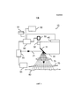
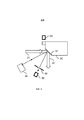
ФИГ. 1 - схематическое изображение устройства для ухода за кожей;FIG. 1 is a schematic illustration of a skin care device;
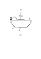
ФИГ. 2 - схематическое изображение на виде сверху аксиконического колесика для устройства ухода за кожей;FIG. 2 is a schematic top view of an axiconical wheel for a skin care device;
ФИГ. 3 - сечение аксиконического колесика, представленного на фиг. 2;FIG. 3 is a sectional view of the axiconic wheel of FIG. 2;
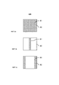
ФИГ. 4a, 4b и 4c - примеры шаблонов обработки кожи;FIG. 4a, 4b, and 4c are examples of skin treatment patterns;
ФИГ. 5a, 5b и 5с - примеры пусковых сигналов;FIG. 5a, 5b, and 5c are examples of triggering signals;
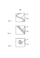
ФИГ. 6a, 6b, 6c, 7a, 7b и 7c - примеры шаблонов обработки кожи, полученные устройством для ухода за кожей согласно изобретению;FIG. 6a, 6b, 6c, 7a, 7b and 7c are examples of skin treatment patterns obtained by the skin care device of the invention;
ФИГ. 8 - некоторые примеры датчиков углового положения в устройстве для ухода за кожей согласно изобретению; иFIG. 8 shows some examples of angular position sensors in a skin care device according to the invention; and
ФИГ. 9 - другой пример датчика углового положения в устройстве для ухода за кожей согласно изобретению.FIG. 9 is another example of an angular position sensor in a skin care device according to the invention.
Подробное описание изобретенияDETAILED DESCRIPTION OF THE INVENTION
На фиг. 1 схематически показано устройство 10 для ухода за кожей. Устройство 10 содержит источник 20 света, в данном случае лазерный источник 20, для образования светового луча 21. Аксиконическое колесико 30 с множеством аксиконических граней 31 отклоняет световой луч 21 через объектив 75 и выходное окно 70 устройства 10 по направлению к коже 80. Каждая аксиконическая грань 31 обеспечивает соответствующее разное направление отражения для светового луча 21. В соответствии с этим во время поворота аксиконического колесика 30 световой луч 21 отражается по направлению к соответствующему множеству разных местоположений на коже 80. На коже 80 световые лучи создают микроскопические зоны обработки (зоны MTZ) термически денатурированной кожной ткани, окруженные незатронутой тканью. Такая обработка стимулирует механизмы восстановления кожи и улучшает внешний вид кожи. Лазерный источник 20 соединен со схемой 60 управления, которая управляет лазерным источником для освещения отдельных аксиконических граней 31 в избранные моменты. Аксиконическое колесико 30 поворачивается приводным средством 40 таким образом, что разные грани 31 колесика 30 последовательно пересекают путь прохождения падающего светового луча 21. Зоны отражающей поверхности разных граней 31 колесика 30 ориентированы под разными углами, чтобы отражать свет 21 в разных направлениях, вызывая воздействие света на кожу 80 в разных позициях в пределах диапазона достижимых позиций.In FIG. 1 schematically shows a
Аксиконическое колесико 30 дополнительно содержит пусковые лепестки 32, которые расположены, примыкая к граням 31. Прохождение пусковых лепестков 32 обнаруживается датчиком 50 лепестков. Датчик 50 лепестков соединен со схемой 60 управления. Частота повторения пускового сигнала, генерируемого датчиком 50 лепестков, зависит от скорости поворота аксиконического колесика 30. Основываясь на пусковом сигнале, схема 60 управления управляет источником 20 света для излучения света во время желаемого участка каждого поворота колесика 30. В примере из предыдущего уровня техники для аксиконического колесика 30 с двенадцатью гранями 31 схема 60 управления может, например, обеспечивать импульс света при прохождении 2, 4, 6 или даже 12 граней за один оборот. Более того, устройство 10 может содержать средство 90 для определения скорости движения руки, с которой пользователь перемещает устройство 10 вдоль поверхности кожи 80. Схема 60 управления способна адаптировать частоту испускания импульсов источником 20 света в зависимости от измеренной скорости движения руки, для того чтобы обеспечить зоны MTZ с более или менее постоянной плотностью, которая не зависит от скорости движения руки.The
Согласно изобретению схема 60 управления устройства 10 не только способна приспосабливать частоту испускания импульсов источником 20 света к скорости поворота аксиконического колесика 30 и измеренной скорости движения руки пользователя, но схема 60 управления выполнена также с возможностью выбора действительных граней 31, которые будут освещаться источником 20 света, чтобы обеспечить на коже 80 заданный шаблон зон MTZ для обработки кожи. Ниже, со ссылками на фиг. 5-9, поясняется, как это достигается. Желаемый шаблон обработки кожи может, например, выбираться пользователем.According to the invention, the
Устройство 10 может дополнительно содержать датчик 95 признаков кожи для определения, например, морщин, повреждений кожи, пигментных пятен или других признаков кожи. Датчик 95 признаков кожи может также использоваться для определения свойств кожи, таких как цвет или влажность кожи. Датчик признаков кожи может, например, содержать видеокамеру для наблюдения кожи 80 или датчик для обнаружения и анализа используемого при обработке светового луча 21 после его отражения от поверхности кожи 80. Датчик признаков кожи соединяется со схемой 60 управления, так что обработка может быть приспособлена к обнаруженным признакам. Например, источник 20 света может управляться таким образом, чтобы обработка затрагивала только обнаруженную морщину или пигментное пятно. Источник 20 света может также управляться таким образом, чтобы не затрагивались выбранные части кажи.The
На фиг. 2 схематически показан вид сверху аксиконического колесика 30 предшествующего уровня техники для устройства ухода за кожей, представленного на фиг. 1. Аксиконическое колесико 30 содержит двенадцать граней 31 для изменения направления и отражения света, поступающего от источника 20 света. Каждой грани 31 придается пусковой лепесток 32. Прохождение пусковых лепестков 32 обнаруживается датчиком 50 лепестков. Источник 20 света управляется в зависимости от пускового сигнала, генерируемого датчиком 50 лепестков. На фиг. 3 показано сечение аксиконического колесика 30, представленного на фиг. 2.In FIG. 2 is a schematic top view of the prior
На фиг. 4a, 4b и 4c даны примеры шаблонов обработки, которые могут быть получены посредством устройства для ухода за кожей согласно фиг. 1, когда используется аксиконическое колесико 30 предшествующего уровня техники согласно фиг. 2. Эти представленные в качестве примера шаблоны зон MTZ на коже 80 получены путем произвольно выбираемого освещения граней 31 на аксиконическом колесике 30 при управляемой частоте испускания импульсов во время перемещения устройства 10 по поверхности кожи 80. Частота испускания импульсов управляется в зависимости от наблюдаемой скорости поворота аксиконического колесика и измеренной скорости движения руки пользователя. Частота испускания импульсов управляется таким образом, чтобы обеспечивалась более или менее постоянная плотность зон MTZ вне зависимости от скорости движения руки. Плотность может быть выбрана, например, в зависимости от выбранного пользователем уровня интенсивности и/или от одного или более автоматически обнаруженных признаков кожи. На этих чертежах на фиг. 4a приведен пример шаблона с высокой плотностью, на фиг. 4b приведен пример шаблона со средней плотностью и на фиг. 4c приведен пример шаблона с низкой плотностью.In FIG. 4a, 4b and 4c give examples of treatment patterns that can be obtained by the skin care device of FIG. 1, when the prior
На фиг 5a показан “нормальный” пусковой лепесток 32 вместе с результирующим пусковым сигналом 132, генерируемым датчиком 50 лепестков. В этом примере все лепестки 32 аксиконического колесика 50 предшествующего уровня техники имеют одинаковую форму (по меньшей мере в отношении размеров, наблюдаемых датчиком 50 лепестков). Частота повторения пускового сигнала 32 зависит от скорости поворота аксиконического колесика 30. Длительность пусковых импульсов зависит от ширины пусковых лепестков 32.FIG. 5a shows a “normal”
На фиг. 5b и 5c приведены примеры пусковых сигналов для устройств 10 согласно изобретению, имеющих аксиконическое колесико 30 с взаимно отличающимися пусковыми лепестками 33, 34. На фиг. 5b по меньшей мере один из пусковых лепестков 33 сделан отличающимся от других. В этом примере лепесток 33 сделан отличающимся благодаря разделению одного нормального лепестка 32 на две части посредством зазора между ними. Каждый раз, когда этот “нестандартный” лепесток 33 проходит мимо датчика 50 лепестков, пусковой сигнал 133 отличается от пускового сигнала 132, генерируемого при прохождении нормальных пусковых лепестков 32. Вместо одного пускового импульса “нестандартный” лепесток 33 вызывает появление двух импульсов с явно меньшей длительностью. Когда обнаруживается такой “нестандартный” лепесток 33, схема управления узнает, что грань 31, связанная с этим “нестандартным” лепестком 33, проходит мимо датчика и, таким образом, узнает также точное положение поворота аксиконического колесика 30. Это позволяет схеме 60 управления обеспечить освещение только выбранных граней 31 аксиконического колесика 30.In FIG. 5b and 5c show examples of trigger signals for
На фиг. 5c представлен альтернативный способ создания “нестандартного” лепестка 34. Ширина такого лепестка 34 составляет половину ширины нормального лепестка 32, что приводит в результате к меньшей длительности пускового импульса в пусковом сигнале 134. Обнаружение такого импульса меньшей длительности указывает на прохождение заданной грани 31, связанной с “нестандартным” лепестком 34.In FIG. 5c shows an alternative way to create a “non-standard”
На фиг. 6a, 6b, 6c, 7a, 7b и 7c представлены примеры шаблонов обработки кожи, полученные устройством для ухода за кожей согласно изобретению. Шаблоны зон MTZ 81 на коже 80 обеспечены избирательным освещением некоторых или всех граней 31 колесика 30 при использовании одной линии сканирования за один раз. Необходимо заметить, что шаблоны, представленные на этих чертежах (и на фиг. 4a, 4b, 4c), относятся к горизонтальной линии сканирования и устройству 10, которое перемещается по поверхности кожи 80 в направлении, перпендикулярном по отношению к линии сканирования. Когда устройство перемещается вдоль поверхности кожи в другом, возможно, не в прямом направлении, тогда шаблон будет соответственно скошен. По желанию выбор граней 31, подлежащих освещению, может зависеть от направления перемещения устройства.In FIG. 6a, 6b, 6c, 7a, 7b, and 7c show examples of skin treatment patterns obtained by the skin care device of the invention. The
На фиг. 6a показан шаблон, который получен освещением, при каждой линии сканирования, всех граней 31 аксиконического колесика 30. Для получения такого шаблона необходимо, чтобы устройство 10 было способно узнавать точное угловое положение колесика 30. Для шаблонов, представленных на фиг. 6b и 6c (и на фиг. 7a, 7b и 7c), важно определять угловое положение колесика, например, обнаруживая, когда заданная одна из множества граней проходит выбранное положение в устройстве 10. При обнаружении прохождения заданной одной из множества граней может быть определена точная последовательность разных ориентаций граней, что позволяет перемещать желаемые шаблоны зон MTZ на коже 80. Однако устройство может использовать любой подходящий датчик углового положения для обнаружения действительного углового положения колесика 30.In FIG. 6a shows a pattern that is obtained by lighting, for each scan line, of all faces 31 of the
На фиг. 6b показан шаблон, полученный отражением светового луча только двумя из граней 31. Эти две грани могут быть или не быть прилегающими друг к другу на аксиконическом колесике 30. Ориентации этих двух граней 31 лишь слегка различаются, в результате чего соответствующие зоны MTZ 81 располагаются по соседству друг с другом. Небольшой вертикальный шаблон может следовать за морщиной или другим признаком кожи, который обнаруживается датчиком признаков кожи в устройстве 10. На фиг. 6c показан шаблон, требующий освещения четырех граней 31 для каждой линии сканирования. Для обоих шаблонов, показанных на фиг. 6b и 6с, одни и те же грани освещаются при каждой линии сканирования (исходя из предположения, что никаких коррекций не сделано для любого отклонения устройства 10 в направлениях, параллельных ориентации линии сканирования).In FIG. 6b shows a pattern obtained by reflecting a light beam by only two of the faces 31. These two faces may or may not be adjacent to each other on the
Необходимо заметить, что для шаблона, представляющего, например, одну вертикальную линию, схеме 60 управления не обязательно нужно знать точные ориентации и последовательность ориентаций всех граней 31 на колесике 30. В такой ситуации будет достаточно обнаруживать прохождение заданной одной из граней и освещать одни и те же грани при каждом обороте колесика 30.It should be noted that for a template representing, for example, one vertical line, the
Для шаблонов на фиг. 7a, 7b и 7c выбираются разные грани при каждой линии сканирования. Для получения этих шаблонов требуется знание положений и ориентаций всех граней. Средство 91 памяти соединяется со схемой управления и хранит заданный шаблон обработки кожи и соотношение между разными угловыми положениями колесика 30 и соответствующими, связанными с ними разными направлениями отражения светового луча 21. Например, средство 91 памяти может хранить базу данных, содержащую перечень номеров граней, их положения на колесике 30 и соответствующие направления отражения. Дополнительно в базе данных может храниться информация о том, какая грань связана с каким идентификационным элементом. Схема 60 управления используется для управления источником 20 света в зависимости от углового положения, обнаруженного датчиком углового положения, в данном примере - момента прохождения идентификационного элемента, таким образом, чтобы при каждом обороте колесика 30 световой луч 21 освещал только поверхность колесика в выбранных угловых положениях или гранях для реализации заданного шаблона обработки кожи. Подобно шаблонам на фиг. 6b и 6c шаблоны, показанные на фиг. 7a, 7b и 7c, могут следовать за конкретными обнаруженными признаками кожи или могут просто выбираться и применяться в позиции, в которой устройство оказывается расположенным на поверхности кожи 80.For the patterns in FIG. 7a, 7b and 7c, different faces are selected for each scan line. Obtaining these patterns requires knowledge of the positions and orientations of all faces. The memory means 91 is connected to the control circuit and stores a predetermined skin processing pattern and the relationship between the different angular positions of the
На фиг. 8 представлены некоторые примеры датчиков углового положения в устройстве ухода за кожей согласно изобретению. Прежде всего, нормальный датчик 50 лепестков, который уже был описан выше, может быть использован для обнаружения лепестка 34, имеющего другую форму. Датчик 50 лепестков может, например, быть способен обнаруживать более короткий лепесток 34, который также был описан выше со ссылкой на фиг. 5c. Альтернативно дополнительный датчик 51 лепестков может быть расположен рядом с первым датчиком 50 лепестков для обнаружения более длинного лепестка 53, который проходит только один раз за каждый оборот колесика 30. Подобный эффект достигается обеспечением одного более короткого лепестка, с тем чтобы дополнительный датчик 51 лепестков обнаруживал все лепестки за исключением более короткого лепестка. Тогда заданная грань 31 является гранью 31, для которой только первый датчик 50 лепестков выдает пусковой импульс.In FIG. 8 illustrates some examples of angular position sensors in a skin care device according to the invention. First of all, a
Другим способом обнаружения конкретных граней 31 является расположение фотоприемника 52 позади граней 31 аксиконического колесика 30 и выполнение заданной одной из граней немного более или менее светопрозрачной, чем другие грани. Когда отличающаяся грань проходит мимо фотоприемника 52, фотоприемник обеспечивает отличающийся сигнал, который, таким образом, указывает на прохождение заданной одной из граней. Если источник 20 света управляется таким образом, что освещаются все грани, тогда используемый для обработки световой луч 21 может также быть использован для обнаружения отличающихся граней. В противном случае может быть предпочтительным использование отдельного дополнительного источника света для этой цели.Another way to detect
В качестве другой альтернативы поверхность колесика может содержать специальную маркировку 54, которая обнаруживается датчиком (не показан), способным распознавать эту маркировку. Например, маркировка 54 является цветным пятнышком, которое обнаруживается видеокамерой, или отражающим пятном, которое обнаруживается сочетанием излучателя света и фотоприемника. Маркировка 54 может быть также отверстием в колесике 30 при расположении излучателя света и фотоприемника на противоположных сторонах колесика 30.As another alternative, the surface of the wheel may contain a
На фиг. 9 представлен другой пример датчика углового положения в устройстве для ухода за кожей согласно изобретению. В этом варианте осуществления используется разница в ориентациях между разными гранями 31. Здесь обеспечен дополнительный источник 22 света и фотоприемник 56 для обнаружения света от дополнительного источника 22 света после его отражения от заданной грани 31. Разные грани 31 отражают свет в разных направлениях. Небольшая щель 55 перед фотоприемником 56 обеспечивает, что только свет, отраженный под точно определенным углом заданной одной из множества граней достигает фотоприемника 56. Свет, который отражается гранями, отличающимися от заданной одной из множества граней, не доходит до фотоприемника 56. Таким образом, фотоприемник 56 обеспечивает пусковой сигнал при каждом прохождении заданной одной из множества граней.In FIG. 9 shows another example of an angular position sensor in a skin care device according to the invention. In this embodiment, the difference in orientations between the different faces 31 is used. An additional
Необходимо заметить, что упомянутые выше варианты осуществления иллюстрируют, а не ограничивают изобретение, и что специалисты в данной области техники смогут разработать многие альтернативные варианты осуществления, не отклоняясь от объема прилагаемых пунктов формулы изобретения. В пунктах формулы изобретения любые ссылочные позиции, заключенные в круглые скобки, не должны рассматриваться как ограничивающие данный пункт. Использование глагола “содержит” и его спряжений не исключает наличия элементов или этапов, отличающихся от оговоренных в пункте формулы изобретении. Использование единственного числа перед элементом не исключает наличия множества таких элементов. Изобретение может быть реализовано посредством аппаратного обеспечения, содержащего несколько четко различимых элементов, и с помощью должным образом запрограммированного компьютера. В относящемся к устройству пункте формулы изобретения, перечисляющем несколько средств, некоторые из этих средств могут быть реализованы одним и тем же компонентом аппаратного обеспечения. Простой факт, что определенные меры упомянуты во взаимно отличающихся зависимых пунктах формулы изобретения, не указывает на то, что сочетание этих мер не может быть выигрышно использовано.It should be noted that the above embodiments illustrate, but do not limit, the invention, and that those skilled in the art will be able to develop many alternative embodiments without departing from the scope of the attached claims. In the claims, any reference numerals enclosed in parentheses should not be construed as limiting this paragraph. The use of the verb “contains” and its conjugations does not exclude the presence of elements or steps that differ from those specified in the claims. The use of the singular in front of an element does not exclude the presence of many such elements. The invention can be implemented by means of hardware containing several clearly distinguishable elements, and by means of a properly programmed computer. In a device claim listing several means, some of these means may be implemented by the same hardware component. The simple fact that certain measures are mentioned in mutually different dependent dependent claims does not indicate that a combination of these measures cannot be advantageously used.
Claims (20)
Applications Claiming Priority (3)
| Application Number | Priority Date | Filing Date | Title |
|---|---|---|---|
| US201261711265P | 2012-10-09 | 2012-10-09 | |
| US61/711,265 | 2012-10-09 | ||
| PCT/IB2013/058798 WO2014057379A1 (en) | 2012-10-09 | 2013-09-24 | Skin treatment device. |
Publications (2)
| Publication Number | Publication Date |
|---|---|
| RU2015110514A RU2015110514A (en) | 2016-10-20 |
| RU2651881C2 true RU2651881C2 (en) | 2018-04-24 |
Family
ID=49817131
Family Applications (1)
| Application Number | Title | Priority Date | Filing Date |
|---|---|---|---|
| RU2015110514A RU2651881C2 (en) | 2012-10-09 | 2013-09-24 | Skin treatment device |
Country Status (8)
| Country | Link |
|---|---|
| US (1) | US10080611B2 (en) |
| EP (1) | EP2906136B1 (en) |
| JP (1) | JP5927351B2 (en) |
| CN (1) | CN104602637B (en) |
| BR (1) | BR112015004399A2 (en) |
| RU (1) | RU2651881C2 (en) |
| TR (1) | TR201808445T4 (en) |
| WO (1) | WO2014057379A1 (en) |
Families Citing this family (1)
| Publication number | Priority date | Publication date | Assignee | Title |
|---|---|---|---|---|
| KR102304955B1 (en) * | 2019-04-03 | 2021-09-27 | 주식회사 루트로닉 | Skin treatment method using medical laser with improved therpaeutic efficacy |
Citations (6)
| Publication number | Priority date | Publication date | Assignee | Title |
|---|---|---|---|---|
| US5371361A (en) * | 1993-02-01 | 1994-12-06 | Spectra-Physics Scanning Systems, Inc. | Optical processing system |
| WO2008008499A2 (en) * | 2006-07-13 | 2008-01-17 | Reliant Technologies, Inc. | Apparatus and method for adjustable fractional optical dermatological treatment |
| US20090213447A1 (en) * | 2005-06-28 | 2009-08-27 | Nidec Sankyo Corporation | Light beam scanning device |
| RU2375009C2 (en) * | 2004-07-22 | 2009-12-10 | Шесер Инк. | Method and device for influencing on tissue |
| US20120197357A1 (en) * | 2011-02-01 | 2012-08-02 | Solta Medical, Inc. | Handheld apparatus for use by a non-physician consumer to fractionally resurface the skin of the consumer |
| US20120253331A1 (en) * | 2011-03-30 | 2012-10-04 | TRIA Beauty | Dermatological Treatment Device with One or More Laser Diode Bar |
Family Cites Families (13)
| Publication number | Priority date | Publication date | Assignee | Title |
|---|---|---|---|---|
| US5743902A (en) * | 1995-01-23 | 1998-04-28 | Coherent, Inc. | Hand-held laser scanner |
| US5546214A (en) | 1995-09-13 | 1996-08-13 | Reliant Technologies, Inc. | Method and apparatus for treating a surface with a scanning laser beam having an improved intensity cross-section |
| CH692221A5 (en) * | 1995-12-19 | 2002-03-15 | Bang & Olufsen As | CD player. |
| US6575964B1 (en) | 1998-02-03 | 2003-06-10 | Sciton, Inc. | Selective aperture for laser delivery system for providing incision, tissue ablation and coagulation |
| US6585725B1 (en) | 1999-04-20 | 2003-07-01 | Nidek Co., Ltd. | Laser irradiation method for laser treatment and laser treatment apparatus |
| ATE345092T1 (en) * | 2000-12-28 | 2006-12-15 | Palomar Medical Tech Inc | APPARATUS FOR THERAPEUTIC ELECTROMAGNETIC RADIATION THERAPY OF THE SKIN |
| US20070179481A1 (en) * | 2003-02-14 | 2007-08-02 | Reliant Technologies, Inc. | Laser System for Treatment of Skin Laxity |
| US7184184B2 (en) | 2003-12-31 | 2007-02-27 | Reliant Technologies, Inc. | High speed, high efficiency optical pattern generator using rotating optical elements |
| US20060239547A1 (en) * | 2005-04-20 | 2006-10-26 | Robinson M R | Use of optical skin measurements to determine cosmetic skin properties |
| WO2008137601A1 (en) | 2007-05-01 | 2008-11-13 | Reliant Technologies, Inc. | Optical scan engine using rotating mirror sectors |
| WO2009099480A1 (en) * | 2008-02-05 | 2009-08-13 | Reliant Technologies, Inc. | Optical pattern generators using axicon segments |
| WO2010109396A1 (en) | 2009-03-25 | 2010-09-30 | Koninklijke Philips Electronics N.V. | Liquid crystal cell manufacture |
| JP6049729B2 (en) * | 2011-09-09 | 2016-12-21 | トリア ビューティ インコーポレイテッド | Devices and methods for radiation-based dermatological treatment |
-
2013
- 2013-09-24 RU RU2015110514A patent/RU2651881C2/en not_active IP Right Cessation
- 2013-09-24 JP JP2015535133A patent/JP5927351B2/en not_active Expired - Fee Related
- 2013-09-24 TR TR2018/08445T patent/TR201808445T4/en unknown
- 2013-09-24 CN CN201380045580.XA patent/CN104602637B/en not_active Expired - Fee Related
- 2013-09-24 EP EP13811004.4A patent/EP2906136B1/en not_active Not-in-force
- 2013-09-24 US US14/431,318 patent/US10080611B2/en not_active Expired - Fee Related
- 2013-09-24 BR BR112015004399A patent/BR112015004399A2/en not_active IP Right Cessation
- 2013-09-24 WO PCT/IB2013/058798 patent/WO2014057379A1/en active Application Filing
Patent Citations (6)
| Publication number | Priority date | Publication date | Assignee | Title |
|---|---|---|---|---|
| US5371361A (en) * | 1993-02-01 | 1994-12-06 | Spectra-Physics Scanning Systems, Inc. | Optical processing system |
| RU2375009C2 (en) * | 2004-07-22 | 2009-12-10 | Шесер Инк. | Method and device for influencing on tissue |
| US20090213447A1 (en) * | 2005-06-28 | 2009-08-27 | Nidec Sankyo Corporation | Light beam scanning device |
| WO2008008499A2 (en) * | 2006-07-13 | 2008-01-17 | Reliant Technologies, Inc. | Apparatus and method for adjustable fractional optical dermatological treatment |
| US20120197357A1 (en) * | 2011-02-01 | 2012-08-02 | Solta Medical, Inc. | Handheld apparatus for use by a non-physician consumer to fractionally resurface the skin of the consumer |
| US20120253331A1 (en) * | 2011-03-30 | 2012-10-04 | TRIA Beauty | Dermatological Treatment Device with One or More Laser Diode Bar |
Also Published As
| Publication number | Publication date |
|---|---|
| BR112015004399A2 (en) | 2017-07-04 |
| CN104602637A (en) | 2015-05-06 |
| JP5927351B2 (en) | 2016-06-01 |
| US10080611B2 (en) | 2018-09-25 |
| US20150257829A1 (en) | 2015-09-17 |
| RU2015110514A (en) | 2016-10-20 |
| TR201808445T4 (en) | 2018-07-23 |
| CN104602637B (en) | 2016-08-24 |
| WO2014057379A1 (en) | 2014-04-17 |
| EP2906136B1 (en) | 2018-04-11 |
| EP2906136A1 (en) | 2015-08-19 |
| JP2015530204A (en) | 2015-10-15 |
Similar Documents
| Publication | Publication Date | Title |
|---|---|---|
| US8784407B2 (en) | Hair removal system and method | |
| US11567175B2 (en) | Apparatuses and method for light detection and ranging | |
| USRE38670E1 (en) | Apparatus for tissue treatment | |
| JP2004532088A (en) | Apparatus and method for identifying intact skin | |
| CN108340071B (en) | Light spot shape detection device | |
| JP2009509140A (en) | Skin optical determination device | |
| JP6449549B2 (en) | Beauty treatment apparatus and method | |
| KR20060134150A (en) | A device for the treatment of skin by means of a radiation beam | |
| WO2009052866A1 (en) | Laser device and method for ablating biological tissue | |
| US20230386249A1 (en) | Presentation attack detection | |
| RU2651881C2 (en) | Skin treatment device | |
| JP6714665B2 (en) | Device and method for light detection and ranging | |
| US20230008801A1 (en) | Increased lidar aperture with refractive optical element | |
| JP6631659B2 (en) | Optical scanning device and laser radar device | |
| JP4647411B2 (en) | ID code interpretation device | |
| JP6522896B2 (en) | Optical scanning device and laser radar device | |
| JP2023115915A5 (en) | ||
| KR20060034093A (en) | System for optic transformation | |
| JP2008054824A (en) | Id token |
Legal Events
| Date | Code | Title | Description |
|---|---|---|---|
| MM4A | The patent is invalid due to non-payment of fees |
Effective date: 20180925 |