RU2647530C2 - Drilling collision avoidance apparatus, methods and systems - Google Patents
Drilling collision avoidance apparatus, methods and systems Download PDFInfo
- Publication number
- RU2647530C2 RU2647530C2 RU2016115367A RU2016115367A RU2647530C2 RU 2647530 C2 RU2647530 C2 RU 2647530C2 RU 2016115367 A RU2016115367 A RU 2016115367A RU 2016115367 A RU2016115367 A RU 2016115367A RU 2647530 C2 RU2647530 C2 RU 2647530C2
- Authority
- RU
- Russia
- Prior art keywords
- transmitter
- well
- magnetic dipoles
- probes
- target well
- Prior art date
Links
Images


Classifications
-
- E—FIXED CONSTRUCTIONS
- E21—EARTH DRILLING; MINING
- E21B—EARTH DRILLING, e.g. DEEP DRILLING; OBTAINING OIL, GAS, WATER, SOLUBLE OR MELTABLE MATERIALS OR A SLURRY OF MINERALS FROM WELLS
- E21B47/00—Survey of boreholes or wells
- E21B47/09—Locating or determining the position of objects in boreholes or wells, e.g. the position of an extending arm; Identifying the free or blocked portions of pipes
-
- E—FIXED CONSTRUCTIONS
- E21—EARTH DRILLING; MINING
- E21B—EARTH DRILLING, e.g. DEEP DRILLING; OBTAINING OIL, GAS, WATER, SOLUBLE OR MELTABLE MATERIALS OR A SLURRY OF MINERALS FROM WELLS
- E21B43/00—Methods or apparatus for obtaining oil, gas, water, soluble or meltable materials or a slurry of minerals from wells
- E21B43/30—Specific pattern of wells, e.g. optimizing the spacing of wells
- E21B43/305—Specific pattern of wells, e.g. optimizing the spacing of wells comprising at least one inclined or horizontal well
-
- E—FIXED CONSTRUCTIONS
- E21—EARTH DRILLING; MINING
- E21B—EARTH DRILLING, e.g. DEEP DRILLING; OBTAINING OIL, GAS, WATER, SOLUBLE OR MELTABLE MATERIALS OR A SLURRY OF MINERALS FROM WELLS
- E21B47/00—Survey of boreholes or wells
- E21B47/02—Determining slope or direction
-
- E—FIXED CONSTRUCTIONS
- E21—EARTH DRILLING; MINING
- E21B—EARTH DRILLING, e.g. DEEP DRILLING; OBTAINING OIL, GAS, WATER, SOLUBLE OR MELTABLE MATERIALS OR A SLURRY OF MINERALS FROM WELLS
- E21B47/00—Survey of boreholes or wells
- E21B47/02—Determining slope or direction
- E21B47/022—Determining slope or direction of the borehole, e.g. using geomagnetism
- E21B47/0228—Determining slope or direction of the borehole, e.g. using geomagnetism using electromagnetic energy or detectors therefor
- E21B47/0232—Determining slope or direction of the borehole, e.g. using geomagnetism using electromagnetic energy or detectors therefor at least one of the energy sources or one of the detectors being located on or above the ground surface
-
- E—FIXED CONSTRUCTIONS
- E21—EARTH DRILLING; MINING
- E21B—EARTH DRILLING, e.g. DEEP DRILLING; OBTAINING OIL, GAS, WATER, SOLUBLE OR MELTABLE MATERIALS OR A SLURRY OF MINERALS FROM WELLS
- E21B47/00—Survey of boreholes or wells
- E21B47/12—Means for transmitting measuring-signals or control signals from the well to the surface, or from the surface to the well, e.g. for logging while drilling
- E21B47/13—Means for transmitting measuring-signals or control signals from the well to the surface, or from the surface to the well, e.g. for logging while drilling by electromagnetic energy, e.g. radio frequency
-
- E—FIXED CONSTRUCTIONS
- E21—EARTH DRILLING; MINING
- E21B—EARTH DRILLING, e.g. DEEP DRILLING; OBTAINING OIL, GAS, WATER, SOLUBLE OR MELTABLE MATERIALS OR A SLURRY OF MINERALS FROM WELLS
- E21B7/00—Special methods or apparatus for drilling
- E21B7/04—Directional drilling
-
- G—PHYSICS
- G01—MEASURING; TESTING
- G01V—GEOPHYSICS; GRAVITATIONAL MEASUREMENTS; DETECTING MASSES OR OBJECTS; TAGS
- G01V3/00—Electric or magnetic prospecting or detecting; Measuring magnetic field characteristics of the earth, e.g. declination, deviation
- G01V3/18—Electric or magnetic prospecting or detecting; Measuring magnetic field characteristics of the earth, e.g. declination, deviation specially adapted for well-logging
- G01V3/20—Electric or magnetic prospecting or detecting; Measuring magnetic field characteristics of the earth, e.g. declination, deviation specially adapted for well-logging operating with propagation of electric current
- G01V3/24—Electric or magnetic prospecting or detecting; Measuring magnetic field characteristics of the earth, e.g. declination, deviation specially adapted for well-logging operating with propagation of electric current using ac
Landscapes
- Life Sciences & Earth Sciences (AREA)
- Engineering & Computer Science (AREA)
- Physics & Mathematics (AREA)
- Geology (AREA)
- Mining & Mineral Resources (AREA)
- Environmental & Geological Engineering (AREA)
- General Life Sciences & Earth Sciences (AREA)
- Fluid Mechanics (AREA)
- Geochemistry & Mineralogy (AREA)
- Geophysics (AREA)
- Electromagnetism (AREA)
- Remote Sensing (AREA)
- General Physics & Mathematics (AREA)
- Geophysics And Detection Of Objects (AREA)
- Earth Drilling (AREA)
- Electrical Discharge Machining, Electrochemical Machining, And Combined Machining (AREA)
- Infusion, Injection, And Reservoir Apparatuses (AREA)
Abstract
Description
Уровень техникиState of the art
[0001] В настоящее время относительно трудным и потенциально дорогостоящим является направление бурового долота через месторождение, на котором густо расположены нефтедобывающие скважины, в качестве части формирования новой скважины без прерывания добычи из каких-либо других скважин в этом месторождении. [0001] Currently, it is relatively difficult and potentially expensive to direct a drill bit through a field in which oil wells are densely located as part of the formation of a new well without interrupting production from any other wells in that field.
Краткое описание чертежейBrief Description of the Drawings
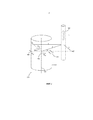
[0002] На фиг. 1 показан вариант осуществления одной или большего количества конфигураций передатчика с магнитными диполями.[0002] In FIG. 1 shows an embodiment of one or more transmitter configurations with magnetic dipoles.
[0003] На фиг. 2A и 2B показан вариант осуществления системы дальнометрии, показывающий различные размещения электродов. [0003] FIG. 2A and 2B show an embodiment of a ranging system showing various electrode arrangements.
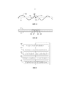
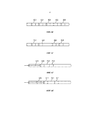
[0004] На фиг. 3A-3C показаны различные варианты осуществления измерения градиента диполей. [0004] FIG. 3A-3C show various embodiments of a dipole gradient measurement.
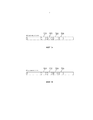
[0005] На фиг. 4A и 4B показаны различные варианты осуществления бурильных стратегий в соответствии с вариантами осуществления, показанными на фиг. 1 и 2.[0005] FIG. 4A and 4B show various embodiments of drilling strategies in accordance with the embodiments shown in FIG. 1 and 2.
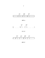
[0006] На фиг. 5 показана блок-схема варианта осуществления способа дальнометрии. [0006] FIG. 5 is a flow chart of an embodiment of a ranging method.
[0007] На фиг. 6A-6G показаны различные варианты осуществления конфигураций электродов для каротажа во время бурения и кабельного каротажа. [0007] FIG. 6A-6G show various embodiments of electrode configurations for logging while drilling and cable logging.
[0008] На фиг. 7A и 7B показаны различные варианты осуществления конфигураций матрицы электродов.[0008] FIG. 7A and 7B show various embodiments of electrode array configurations.
[0009] На фиг. 8 показана кабельная система.[0009] FIG. 8 shows a cable system.
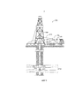
[0010] На фиг. 9 показана система буровой установки.[0010] FIG. 9 shows a rig system.
Подробное описаниеDetailed description
[0011] По мере выработки легких для доступа и легких для добычи углеводородных ресурсов оставшиеся скважины становятся более трудными для доступа. Кроме того, мировая потребность в углеводородах постоянно растет, удовлетворение этой потребности может применять развитие более прогрессивных процедур извлечения, таких как применение метода парогравитационного дренажа (SAGD, Steam Assisted Gravity Drainage). Технология SAGD нацелена на проблему подвижности скважин с тяжелой нефтью посредством нагнетания высокотемпературного пара высокого давления, который снижает вязкость нефти и обеспечивает возможность легкого извлечения. Такое нагнетание выполняют из ствола скважины (например, нагнетательной скважины, опорной скважины), который пробурен параллельно добывающей скважине (например, целевой скважине) на расстоянии порядка нескольких метров друг от друга. Размещение опорной скважины должно выполняться с очень небольшим запасом расстояния, поскольку слишком близкое размещение подвергло бы добывающую скважину воздействию очень высоких давления и температуры, а слишком далекое размещение снизило бы эффективность процесса. Традиционные технологии разведки могут испытывать недостатки от расширения конуса неопределенности, поскольку скважина получается длиннее, и они не могут достигать точности в размещении, которая используется в этом применении. [0011] As light for access and light for producing hydrocarbon resources are produced, the remaining wells become more difficult to access. In addition, the global demand for hydrocarbons is constantly growing, the satisfaction of this need can apply the development of more advanced extraction procedures, such as the use of steam gravity drainage (SAGD, Steam Assisted Gravity Drainage). SAGD technology addresses the mobility of heavy oil wells by injecting high-temperature, high-pressure steam, which reduces the viscosity of the oil and allows easy recovery. Such injection is performed from a wellbore (e.g., injection well, reference well), which is drilled parallel to the production well (e.g., target well) at a distance of about several meters from each other. The placement of the reference well should be carried out with a very small margin, since placing it too close would expose the producing well to very high pressures and temperatures, and placing it too far would reduce the efficiency of the process. Conventional exploration technologies may suffer from the expansion of the uncertainty cone as the well is longer and they cannot achieve the placement accuracy used in this application.
[0012] Различные варианты осуществления, раскрытые в настоящем документе, используют комбинацию передатчиков с магнитными диполями и электродных измерений напряжения. Передатчики с магнитными диполями могут быть размещены в скважине и/или на поверхности геологической формации. По сравнению с возбуждением поверхностного типа различные варианты осуществления не производят нежелательные индукционные сигналы на приемники из-за вращения магнитных датчиков относительно земли. Это обеспечивает возможность выполнения измерений во время вращения, что может устранять одно из ограничений применений в дальнометрии.[0012] The various embodiments disclosed herein utilize a combination of magnetic dipole transmitters and electrode voltage measurements. Transmitters with magnetic dipoles can be placed in the well and / or on the surface of the geological formation. Compared to surface type excitation, various embodiments do not produce unwanted induction signals to the receivers due to the rotation of the magnetic sensors relative to the ground. This makes it possible to take measurements during rotation, which can eliminate one of the limitations of long-range applications.
[0013] Как использовано в настоящем документе, целевая скважина может быть ликвидированной или нефтедобывающей или газодобывающей скважиной, которая существует в месторождении, и которую следует избегать при бурении последующей скважины. Целевая скважина также может быть существующей скважиной, которая зафонтанировала и подлежит пересечению на выбранной глубине под поверхностью земли разгрузочной скважиной. В соответствии с альтернативным вариантом осуществления целевая скважина может представлять некоторую другую аномалию, расположенную в земле, такую как электропроводящую геологическую формацию, скважинную трубу, бурильную колонну в необсаженной скважине или некоторый другой электропроводящий материал, который может быть целью для пересечения или избегания. Для целей настоящего раскрытия такой материал будет называться целевой скважиной или трубой целевой скважины. [0013] As used herein, the target well may be an abandoned or oil producing or gas producing well that exists in the field and which should be avoided when drilling a subsequent well. The target well may also be an existing well that has been spouted and is to be crossed at a selected depth below the surface of the earth by a discharge well. According to an alternative embodiment, the target well may be some other anomaly located in the ground, such as an electrically conductive geological formation, a downhole pipe, a drill string in an open hole or some other electrically conductive material that may be a target for crossing or avoiding. For the purposes of the present disclosure, such material will be called the target well or pipe of the target well.
[0014] Вблизи целевой скважины может быть вторая буровая скважина, которая пробуривается и которую следует направлять таким образом, чтобы пересекать целевую скважину или избегать ее. Для удобства вторая буровая скважина будет называться опорной скважиной. Опорная скважина обычно начинается в устье скважины на поверхности земли и может быть относительно близко к устью целевой скважины или может располагаться на расстоянии. В устье скважины подсекции или утяжеленные бурильные трубы закрепляют конец к концу для формирования бурильной колонны и опускают в скважину в ходе буровых работ обычным способом. Во внутреннюю часть отверстия колонны могут подавать буровой раствор в качестве фитинга, снова обычным способом. [0014] In the vicinity of the target well, there may be a second borehole that is being drilled and which should be directed so as to cross the target well or to avoid it. For convenience, the second borehole will be called a reference well. A reference well typically begins at the wellhead on the surface of the earth and may be relatively close to the wellhead of the target well or may be spaced apart. At the wellhead, subsections or weighted drill pipes fasten the end to the end to form the drill string and lower it into the well during drilling operations in the usual way. Drilling fluid may be supplied to the inside of the column opening as a fitting, again in the usual way.
[0015] Устройство для дальнометрии может содержать две части: (1) передающее устройство с магнитными диполями, которое генерирует переменные токи (АС) на трубе целевой скважины, и (2) приемник с электродами, который измеряет абсолютное и дифференциальное напряжения, обусловленные этими АС токами, от электродов, размещенных в устье скважины, на небольшой глубине вблизи поверхности геологической формации и/или в контакте с целевой скважиной. Передающее устройство с магнитными диполями может быть размещено в виде части каротажного прибора, размещаемого в опорной скважине. Относительное расстояние и направление от опорной скважины к целевой скважине могут быть определены при помощи анализа измеренных напряжений на основании абсолютных и дифференциальных возбуждений магнитных диполей. [0015] A ranging device may comprise two parts: (1) a transmitter with magnetic dipoles that generates alternating currents (AC) on the pipe of the target well, and (2) a receiver with electrodes that measures the absolute and differential voltages caused by these speakers currents from electrodes located at the wellhead at a shallow depth near the surface of the geological formation and / or in contact with the target well. A transmitting device with magnetic dipoles can be placed as part of a logging tool placed in a reference well. The relative distance and direction from the reference well to the target well can be determined by analyzing the measured stresses based on the absolute and differential excitations of the magnetic dipoles.
[0016] Передатчики с магнитными диполями, работающие на относительно низких частотах (например, 0,02-250 Гц), могут быть использованы для индуцирования АС в целевой скважине. Один или большее количество передатчиков с магнитными диполями может быть использовано в качестве части передающего устройства с магнитными диполями для генерации АС. [0016] Magnetic dipole transmitters operating at relatively low frequencies (eg, 0.02-250 Hz) can be used to induce speakers in the target well. One or more transmitters with magnetic dipoles can be used as part of a transmitter with magnetic dipoles to generate speakers.
[0017] На фиг. 1 показан вариант осуществления конфигурации передающего устройства 206 с магнитными диполями, использующего один передатчик 103 с магнитными диполями, как представлено посредством Hy2, расположенный в опорной скважине 100 для индуцирования АС в целевой скважине 120. В соответствии с вариантом осуществления, где измерения выполняются в то время, когда передатчик вращается, один физический передатчик 103 с магнитными диполями может быть использован для синтеза четырех результатов 101-104 магнитных диполей при различных углах вращения, если была выполнена сортировка измерений. Четыре результата 101-104 магнитных диполей представлены посредством Hx1, Hx2, Hy1 и Hy2. На фиг. 1 показаны синтезированные передатчики 101, 102, 104 с магнитными диполями, представленные пунктирными линиями, тогда как физический передатчик 103 с магнитными диполями представлен сплошной линией. В соответствии с альтернативным вариантом осуществления все передатчики с магнитными диполями могут быть физическими. Например, каждый передатчик 101-104 с магнитными диполями может быть физическим передатчиком с магнитными диполями. Хотя электрически более сложная система, имеющая физические передатчики с магнитными диполями, может уменьшать ошибки из-за операций синтеза. [0017] FIG. 1 shows an embodiment of a configuration of a
[0018] Передатчики 101-104 с магнитными диполями могут быть размещены к наружной поверхности каротажного прибора. Если используется более, чем один физический передатчик 101-104 с магнитными диполями, они могут быть отделены радиально от других передатчиков с магнитными диполями и расположены, по существу, на равном расстоянии от осевой средней линии 130 опорной скважины 100, но на противоположной стороне опорной скважины 100 от противоположных передатчиков с магнитными диполями. [0018] Transmitters 101-104 with magnetic dipoles can be placed to the outer surface of the logging tool. If more than one physical transmitter 101-104 with magnetic dipoles is used, they can be separated radially from other transmitters with magnetic dipoles and located essentially at an equal distance from the
[0019] Передатчики 101-104 с магнитными диполями могут индуцировать закрытые электрические силовые линии в геологической формации и токи по трубе 120 целевой скважины. Индуцированные токи при таких относительно низких частотах могут достигать расстояний, больше чем 10 000 футов (3048 метров). Таким образом, такая реализация хорошо работает для применений SAGD.[0019] Transmitters 101-104 with magnetic dipoles can induce closed electrical field lines in the geological formation and currents through the
[0020] В некоторых случаях передатчики 101-104 с магнитными диполями работают в дифференциальном режиме, где данные напряжения при различных углах вращения диполя вычитаются. Для того чтобы улучшать уровень сигнала напряжения, соответствующего дифференциальным данным, передатчики с магнитными диполями могут быть помещены настолько далеко от осевой средней линии указанного прибора, как это возможно. Кроме того, магнитные диполи на противоположных сторонах оси указанного прибора (т.е. которые разделены на 180 градусов) могут быть использованы в вычитании. Другой вариант осуществления для получения дифференциального возбуждения состоит в помещении антенны 101, 103 с противоположными обмотками на двух сторонах указанного прибора. Это может физически уравновешивать токи и способствовать калибровке указанного прибора.[0020] In some cases, magnetic dipole transmitters 101-104 operate in differential mode, where voltage data at various dipole angles of rotation are subtracted. In order to improve the level of the voltage signal corresponding to the differential data, transmitters with magnetic dipoles can be placed as far from the axial center line of the specified device as possible. In addition, magnetic dipoles on opposite sides of the axis of the indicated device (i.e., which are divided by 180 degrees) can be used in subtraction. Another embodiment for obtaining differential excitation is to place the
[0021] Для того чтобы улучшать управляемость бурового долота, передатчики 101-104 с магнитными диполями могут быть помещены так близко к долоту, как это возможно (например, рядом с ним). В применениях SAGD бурильная колонна, расположенная в опорной скважине 100, может быть, по существу, параллельной целевой трубе 120, так что размещение передатчиков 101-104 с магнитными диполями может быть менее важным с точки зрения управляемости. В соответствии с другими вариантами осуществления передатчики с магнитными диполями помещены где-либо на бурильной колонне, например, на долоте.[0021] In order to improve the controllability of the drill bit, transmitters 101-104 with magnetic dipoles can be placed as close to the bit as possible (for example, next to it). In SAGD applications, the drill string located in the reference well 100 may be substantially parallel to the
[0022] На фиг. 2A и 2B показан вариант осуществления системы дальнометрии, показывающий различные размещения электродов. Система дальнометрии может содержать приемник и контроллер 201, соединенный с множеством электродов 202, 203. Приемник и контроллер 201 может содержать вольтметр для измерения абсолютного и дифференциального напряжений между электродами 202, 203. Приемник и контроллер 201 также может содержать управляющие схемы для управления работой системы, а также и выполнения любых способов дальнометрии, таких как показанный на фиг. 5. Варианты осуществления, показанные на фиг. 2A и 2B, приведены только для целей иллюстрации, поскольку могут быть использованы другие системы и другие местоположения для электродов.[0022] FIG. 2A and 2B show an embodiment of a ranging system showing various electrode arrangements. The ranging system may include a receiver and
[0023] На фиг. 2A и 2B показаны целевая скважина 204 и опорная скважина 205. Передающее устройство 206 с магнитными диполями, которое содержит указанный один или большее количество передатчиков 101-104 с магнитными диполями, показано расположенным в опорной скважине 205. Передающее устройство 206 с магнитными диполями может генерировать АС на трубе 205 опорной скважины для того, чтобы генерировать электрическое поле 207, которое может создавать дифференциал напряжения, как измеряется электродами 202, 203. [0023] FIG. 2A and 2B show a target well 204 and a
[0024] В соответствии с вариантом осуществления, показанным на фиг. 2А, первый электрод 202 расположен на поверхности геологической формации. Второй электрод 203 присоединен к целевой скважине 204. Например, электрод 203 может быть присоединен посредством изолированного провода к устью или к области, окружающей устье целевой скважины 204. Если присоединен к области, окружающей устье целевой скважины, этот электрод может быть расположен на относительно небольшой глубине (например, < 6м). В соответствии с этим вариантом осуществления измерение напряжения выполняют по трубе через устье и поверхностные геологические формации. [0024] According to the embodiment shown in FIG. 2A, a
[0025] В соответствии с вариантом осуществления, показанным на фиг. 2В, первый электрод 202 расположен на поверхности геологической формации. Второй электрод 203 расположен в трубе 204 целевой скважины. В соответствии с этим вариантом осуществления измерение напряжения выполняют с использованием изолированного кабеля, который размещен в целевой трубе, в соответствии с предпочтительным вариантом осуществления, вблизи области, намеченной для бурения SAGD. [0025] According to the embodiment shown in FIG. 2B, a
[0026] В соответствии с обоими вариантами осуществления, показанными на фиг. 2A и 2B, измеренная разность напряжений указывает на величину токов, индуцированных в трубе 204 целевой скважины. Для того чтобы минимизировать сопротивление нагрузки, присоединенной к источнику, электродный контакт может быть выполнен с возможностью уменьшения сопротивления электрода, насколько это возможно. Уменьшение нагрузки может улучшать отношение сигнала к шуму для измерения напряжения. В соответствии с вариантом осуществления со скважинными электродами могут использовать механический зажим. В горизонтальной или по существу горизонтальной части трубы длинный участок проводящего материала, как часть электрода, может быть соединен с нижней стороной трубы и может быть протолкнут к трубе с помощью силы тяжести. [0026] In accordance with both embodiments shown in FIG. 2A and 2B, the measured voltage difference indicates the magnitude of the currents induced in the
[0027] Неожидаемые колебания распределения тока по трубе могут приводить к относительно небольшим измеренным напряжениям между электродами или инвертированию знака измеренного напряжения. Проблема с небольшими измеренными напряжениями может быть решена при помощи использования различной частоты возбуждения АС или положения передающего устройства с магнитными диполями, которое, как предполагается, будет производить различное распределение тока на трубе опорной скважины. Проблема с инвертированием знака напряжения может быть обнаружена на основании сравнения между различными прошлыми измерениями напряжения или различной частотой или перемещения положений передатчика.[0027] Unexpected fluctuations in the distribution of current through the pipe can result in relatively small measured voltages between the electrodes or invert the sign of the measured voltage. The problem with small measured voltages can be solved by using different frequency of excitation of the speaker or the position of the transmitting device with magnetic dipoles, which, as expected, will produce a different current distribution on the pipe of the reference well. A problem with inverting the voltage sign can be detected based on a comparison between different past voltage measurements or different frequencies or moving transmitter positions.
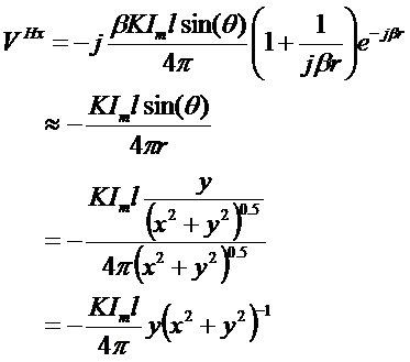
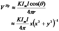
[0028] Возбуждение целевой скважины посредством одного передатчика с магнитными диполями может быть иллюстрировано при помощи следующих уравнений, где r - расстояние, на котором один передатчик с магнитными диполями находится от ориентированной по z трубе целевой скважины. Разность напряжений на двух дальних конечных точках трубы целевой скважины может быть приблизительно выражена так:[0028] Excitation of the target well by means of a single transmitter with magnetic dipoles can be illustrated by the following equations, where r is the distance at which one transmitter with magnetic dipoles is from the z-oriented pipe of the target well. The voltage difference at the two far end points of the pipe of the target well can be approximately expressed as follows:
![]()
![]()
где V - приблизительное напряжение, E - вектор напряженности электрического поля, C- контур вдоль трубы, Ez - компонент по оси z электрического поля в таком положении трубы, которое является ближайшим к магнитному диполю, и K - коэффициент пропорциональности, который зависит от свойств формации и трубы. В случае одного направленного по оси x передатчика с магнитными диполями в геометрии, показанной на фиг. 1, напряжение, генерируемое на двух точках в однородной формации, может быть записано как:where V is the approximate voltage, E is the electric field vector, C is the contour along the pipe, E z is the component along the z axis of the electric field in the position of the pipe that is closest to the magnetic dipole, and K is the proportionality coefficient, which depends on the properties formations and pipes. In the case of one x-directional transmitter with magnetic dipoles in the geometry shown in FIG. 1, the voltage generated at two points in a homogeneous formation can be written as:
где ![]()
![]()
![]()
![]()
[0029] "Дифференциальное" возбуждение направленного по оси y магнитного диполя, объединенного с направленным по оси y магнитным диполем противоположного направления (как показано на фиг. 1), произведет[0029] The "differential" excitation of the y-directional magnetic dipole combined with the y-directional magnetic dipole of the opposite direction (as shown in Fig. 1) will produce
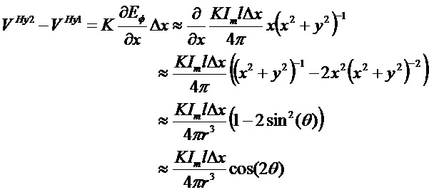
[0030] Аналогично, дифференциальное возбуждение двух направленных по оси x магнитных диполей произведет[0030] Similarly, differential excitation of two magnetic dipoles directed along the x axis will produce
![]()
![]()
[0031] Можно наблюдать, что посредством анализа абсолютных измерений с направленными по оси x и направленными по оси y магнитными диполями возможно определять ориентацию трубы следующим образом:[0031] It can be observed that by analyzing the absolute measurements with the magnetic dipoles directed along the x axis and directed along the y axis, it is possible to determine the pipe orientation as follows:
![]()
![]()
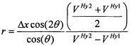
[0032] Взяв отношение абсолютных измерений к измерениям дифференциального возбуждения как для направленных по оси x, так и для направленных по оси y возбуждений, возможно получать расстояние до трубы следующим образом:[0032] By taking the ratio of absolute measurements to differential excitation measurements for both the x-axis and y-axis excitations, it is possible to obtain the distance to the pipe as follows:
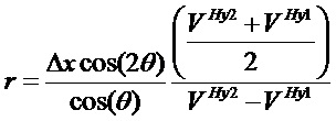
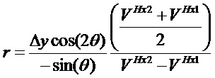
[0033] Хотя уравнения (7) и (8) обеспечивают расстояние до трубы целевой скважины, они имеют комплиментарное численное поведение. Уравнение (7) в численном отношении наиболее устойчиво при θ=180k, тогда как уравнение (8) наиболее устойчиво при θ=90+180k (k - целое число) из-за размера знаменателя. Выбор уравнения для вычисления расстояния наилучшим способом выполняется на основании того, какое из уравнений более устойчиво для заданного диапазона θ.[0033] Although equations (7) and (8) provide a distance to the pipe of the target well, they have complementary numerical behavior. Equation (7) is numerically most stable at θ = 180k, while equation (8) is most stable at θ = 90 + 180k (k is an integer) due to the denominator size. The choice of the equation for calculating the distance in the best way is based on which of the equations is more stable for a given range θ.
[0034] Описанные выше варианты осуществления могут быть использованы в применениях SAGD на практике. Однако, из уравнений (7) и (8) можно видеть, что когда θ=45+90k, знаменатель стремится к нулю, что указывает на то, что знаменатель (измерение) также должен будет стремиться к нулю. Это также является неустойчивым в численном отношении условием, которое содержит "слепое пятно" для измерений дифференциального возбуждения. Существует область, в которой выполненные измерения не будут такими полезными или точными, как в других областях.[0034] The embodiments described above can be used in SAGD applications in practice. However, it can be seen from equations (7) and (8) that when θ = 45 + 90k, the denominator tends to zero, which indicates that the denominator (measurement) should also tend to zero. It is also a numerically unstable condition that contains a blind spot for differential excitation measurements. There is an area in which the measurements taken will not be as useful or accurate as in other areas.
[0035] На фиг. 3A-3C показаны различные варианты осуществления для конфигураций измерения возбуждения 3-, 4- и 8-диполей соответственно. Конфигурации измерений возбуждения различных диполей показаны только для целей иллюстрации. Нет ограничений как на количество передатчиков с магнитными диполями, используемых для генерации различных конфигураций, так и на количество конфигураций измерения. [0035] FIG. 3A-3C show various embodiments for 3-, 4-, and 8-dipole excitation measurement configurations, respectively. The configurations of the excitation measurements of various dipoles are shown for illustrative purposes only. There are no restrictions on the number of transmitters with magnetic dipoles used to generate various configurations, or on the number of measurement configurations.
[0036] Вариант осуществления с передатчиком с тремя магнитными диполями, показанный на фиг. 3A, и вариант осуществления с передатчиком с четырьмя магнитными диполями, показанный на фиг. 3В, могут испытывать недостатки от проблемы слепого пятна. Каждый из передатчиков с магнитными диполями представлен посредством Hy, Hx1, Hx2 для варианта осуществления с передатчиком с 3-мя магнитными диполями, показанный на фиг. 3А, и посредством Hx1, Hx2, Hy1 и Hy2 для варианта осуществления с передатчиком с 4-мя магнитными диполями, показанный на фиг. 3В. В случае цели, находящейся в направлении по оси x или оси y, местоположения, имеющие точки наивысшей численной устойчивости, показаны, как местоположения 301-308. Области, которые находятся в середине этих местоположений 301-308, т.е. местоположений, составляющих угол в 45 градусов к оси x или оси y, могут рассматриваться, как слепые пятна. [0036] An embodiment with a transmitter with three magnetic dipoles, shown in FIG. 3A, and an embodiment with a transmitter with four magnetic dipoles, shown in FIG. 3B may suffer from blind spot problems. Each of the transmitters with magnetic dipoles is represented by H y , H x1 , H x2 for an embodiment with a transmitter with 3 magnetic dipoles, shown in FIG. 3A, and by H x1 , H x2 , H y1 and H y2 for an embodiment with a transmitter with 4 magnetic dipoles, shown in FIG. 3B. In the case of a target located in the x-axis or y-axis direction, locations having points of highest numerical stability are shown as locations 301-308. The areas that are in the middle of these locations are 301-308, i.e. locations that make up an angle of 45 degrees to the x-axis or y-axis can be considered blind spots.
[0037] В третьей конфигурации, показанной на фиг. 3С, направления наивысшей чувствительности для двух наборов диполей указаны как местоположения 310-313 и местоположения 320-323 соответственно, если находится в направлении по оси x или оси y. Однако если цель составляет угол 45 градусов с осью x или осью y, местоположения 320-323 имеют наивысшую чувствительность. В результате конфигурация, показанная на фиг. 3С, может производить устойчивый результат для всех измерений, тогда как конфигурации, показанные на фиг. 3A и 3B, могут производить неустойчивые результаты на основании относительной ориентации трубы целевой скважины. В случае выполнения измерений во время вращения бурильной колонны большое количество измерений может быть выполнено при различных углах вращения, производя вариации, которые являются достаточными для устранения выбранных слепых пятен. [0037] In the third configuration shown in FIG. 3C, the directions of highest sensitivity for the two sets of dipoles are indicated as locations 310-313 and locations 320-323, respectively, if located in the x-axis or y-axis direction. However, if the target is 45 degrees with the x axis or y axis, locations 320-323 have the highest sensitivity. As a result, the configuration shown in FIG. 3C can produce a consistent result for all measurements, while the configurations shown in FIG. 3A and 3B may produce erratic results based on the relative orientation of the target well pipe. In the case of measurements during the rotation of the drill string, a large number of measurements can be performed at different angles of rotation, producing variations that are sufficient to eliminate the selected blind spots.
[0038] Каждый из передатчиков с магнитными диполями при активации (например, при подаче питания) имеет магнитный момент. Как известно из уровня техники, магнитный момент является величиной, которая определяет силу, которую передатчик с магнитными диполями может прилагать на электрические токи, и крутящий момент, который магнитное поле будет прилагать на передатчик с магнитными диполями. Передатчик с магнитными диполями может иметь магнитный момент, который направлен в противоположном направлении от магнитного момента радиально отделенного передатчика с магнитными диполями. [0038] Each of the transmitters with magnetic dipoles when activated (for example, when applying power) has a magnetic moment. As is known from the prior art, the magnetic moment is a quantity that determines the force that a transmitter with magnetic dipoles can exert on electric currents, and the torque that a magnetic field will exert on a transmitter with magnetic dipoles. A transmitter with magnetic dipoles may have a magnetic moment that is directed in the opposite direction from the magnetic moment of a radially separated transmitter with magnetic dipoles.
[0039] Например, из четырех передатчиков с магнитными диполями Hx1, Hx2, Hy1 и Hy2 с фиг. 3B, Hx1 и Hx2 радиально отделены друг от друга и генерируют магнитные моменты в противоположном друг от друга направлении. Аналогично, Hy1 и Hy2 радиально отделены друг от друга и генерируют магнитные моменты в противоположном друг от друга направлении. В соответствии с вариантом осуществления радиально отделенные передатчики с магнитными диполями могут быть, по существу, на равном расстоянии от осевой средней линии опорной скважины и, по существу, в противоположном направлении по сравнению с другими передатчиками с магнитными диполями из указанных радиально отделенных передатчиков с магнитными диполями.[0039] For example, of the four transmitters with magnetic dipoles H x1 , H x2 , H y1 and H y2 of FIG. 3B, H x1 and H x2 are radially separated from each other and generate magnetic moments in the opposite direction from each other. Similarly, H y1 and H y2 are radially separated from each other and generate magnetic moments in the opposite direction from each other. According to an embodiment, the radially separated transmitters with magnetic dipoles can be substantially equal to the distance from the axial midline of the reference well and substantially in the opposite direction compared to other transmitters with magnetic dipoles from said radially separated transmitters with magnetic dipoles .
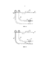
[0040] На фиг. 4A и 4B показаны различные варианты осуществления бурильных стратегий с использованием системы дальнометрии и способов дальнометрии, раскрытых в настоящем документе. На фиг. 4А показан подход триангуляции, где может быть выполнено множество измерений 400-403 ориентаций (θ). Эти измерения 400-403 могут быть наложены на данные разведки для выполнения триангуляции положения опорной скважины 205 относительно целевой скважины 204, как показано. [0040] FIG. 4A and 4B show various embodiments of drilling strategies using the ranging system and ranging methods disclosed herein. In FIG. 4A shows a triangulation approach where multiple measurements of 400-403 orientations (θ) can be performed. These measurements 400-403 may be superimposed on the exploration data to triangulate the position of the reference well 205 relative to the target well 204, as shown.
[0041] На фиг. 4В показано, как может быть выполнена дальнометрия, когда доступно достоверное измерение расстояния. В соответствии с этим вариантом осуществления нет необходимости в триангуляции, и опорная скважина 205 может быть пробурена без движения по спирали вокруг целевой скважины 204. Этот вариант осуществления может быть использован для помощи в регулировке расстояния между скважинами с использованием множества измерений 420-423 относительного расстояния между опорной скважиной 205 и целевой скважиной 204. [0041] FIG. 4B shows how ranging can be performed when reliable distance measurement is available. In accordance with this embodiment, triangulation is not necessary, and the reference well 205 can be drilled without spiraling around the target well 204. This embodiment can be used to help adjust the distance between the wells using a plurality of measurements 420-423 of the relative distance between reference well 205 and target well 204.
[0042] В тех вариантах осуществления, где требуется пересечение скважин, могут быть использованы оба варианта осуществления, показанные на 4A и 4B. В применениях SAGD может быть использован вариант осуществления, показанный на фиг. 4В, поскольку оптимальное положение для нагнетательной скважины находится выше добывающей скважины из-за соображений силы тяжести.[0042] In those embodiments where well intersection is required, both embodiments shown in 4A and 4B can be used. In SAGD applications, the embodiment shown in FIG. 4B, since the optimal position for the injection well is above the producing well due to gravity considerations.
[0043] На фиг. 5 показана блок-схема варианта осуществления работы системы дальнометрии, как было обсуждено ранее. Сначала пробуривают одну из опорной скважины (например, нагнетательной скважины) или целевой скважины (например, добывающей скважины). Традиционно, первой пробуривают добывающую скважину, поскольку она должна быть размещена в пласте в оптимальном положении для выработки большего количества углеводородов. Приспособление для размещения скважин, такое как азимутальный прибор каротажа сопротивления или прибор каротажа сопротивления со сверхбольшим радиусом исследования, может быть использован для размещения добывающей скважины на выбранных расстояниях от смежных слоев в пласте. Данные разведки могут быть собраны при бурении первой скважины для помощи в направлении второй скважины.[0043] FIG. 5 shows a block diagram of an embodiment of the operation of a ranging system, as previously discussed. First, one of the reference well (e.g., injection well) or the target well (e.g., production well) is drilled. Traditionally, the production well is drilled first, since it must be placed in the formation in an optimal position to produce more hydrocarbons. A device for placing wells, such as an azimuthal resistance logging tool or a resistance logging tool with an extremely large research radius, can be used to place a producing well at selected distances from adjacent layers in the formation. Exploration data may be collected while drilling the first well to aid in the direction of the second well.
[0044] Затем могут начинать бурение второй скважины с наклонного участка, направляемого либо информацией разведки, либо абсолютной или градиентной информацией от прибора для измерения дальности. После наклонного участка выполняют процедуру удержания второй скважины параллельно и на требуемом расстоянии к первой скважине. Раскрытая система дальнометрии может обеспечивать возможность по существу одинакового расстояния, или она может следовать предписанному или управляемому изменяемому расстоянию на основании локальных характеристик формации. [0044] Then, drilling of the second well may then begin from an inclined section guided either by exploration information or by absolute or gradient information from a ranging device. After the inclined section, the procedure of holding the second well in parallel and at the required distance to the first well is performed. The disclosed ranging system may allow substantially the same distance, or it may follow a prescribed or controlled variable distance based on local characteristics of the formation.
[0045] Низкий уровень шума, который требуется для дальнометрии, может быть достигнут посредством остановки бурения во время дальнометрических измерений. Время между остановкой бурения и началом дальнометрии может быть оптимизировано для снижения шума из-за биения труб, а также минимизировано время простоя. Аналогично, продолжительность дальнометрической деятельности может быть выбрана таким образом, чтобы отклонять шум электрической системы и магнитной среды, в то же время снижая время простоя. [0045] The low noise level that is required for ranging can be achieved by stopping drilling during long-range measurements. The time between a drilling stop and the start of ranging can be optimized to reduce noise due to pipe runout, and downtime is minimized. Similarly, the duration of long-range activity can be chosen so as to reject the noise of the electrical system and the magnetic environment, while reducing downtime.
[0046] Во время дальнометрии передатчики с магнитными диполями и электродные приемники активированы по существу одновременно 500 от поверхности, либо автоматически, либо вручную. Во время возбуждения с помощью передатчиков с магнитными диполями электроды могут быть активированы от поверхности или посредством скважинного алгоритма, который обнаруживает токи трубы. [0046] During ranging, magnetic dipole transmitters and electrode receivers are activated substantially simultaneously 500 from the surface, either automatically or manually. During excitation using transmitters with magnetic dipoles, the electrodes can be activated from the surface or through a borehole algorithm that detects pipe currents.
[0047] Между первым и вторым электродами измеряют 503 сигналы дифференциального напряжения, сгенерированные из-за АС в трубе опорной скважины. Затем могут определять 504 абсолютное и дифференциальное напряжения, а также определять 505 относительное направление и относительное расстояние до целевой скважины, используя уравнения, как описано выше. Траекторию пробуриваемой скважины могут регулировать с использованием вычисленных относительного направления и относительного расстояния до целевой скважины 506. Этот способ могут повторять до тех пор, пока скважина пробуривается, и требуется дальнометрия. [0047] Between the first and second electrodes, 503 differential voltage signals generated due to the speakers in the reference well pipe are measured. Then, absolute and
[0048] Поскольку результаты направления и расстояния основаны на координатной системе приемника, могут выполнять преобразование для того, чтобы преобразовывать эти результаты в земные координаты или другую координатную систему, которая может быть использована в геонавигации бурового долота. Для измерения ориентации приемника и выполнения преобразования, упомянутого выше, могут использовать информацию о гравитации и магнитном поле Земли. [0048] Since the results of direction and distance are based on the coordinate system of the receiver, they can perform the conversion in order to convert these results into terrestrial coordinates or another coordinate system that can be used in geosteering the drill bit. To measure the orientation of the receiver and perform the conversion mentioned above, information on the gravity and magnetic field of the Earth can be used.
[0049] Процедуру дальнометрии, описанную выше, могут выполнять на определенных интервалах глубины, что улучшает характеристики точности геонавигации и снижает время бурения. Для регулировки этих интервалов могут использовать априорную информацию. Например, если данные разведки первой скважины указывают на то, что предполагается, что эта скважина будет пологой, то интервалы между дальнометрическими измерениями могут быть увеличены. Если предполагается, что скважина будет иметь резко искривившийся ствол, дальнометрические измерения могут выполнять более быстро. Вблизи конца скважины токи ведут себя иначе по сравнению с другими секциями, поскольку линия прохождения тока изменена. Для того, чтобы устранить неблагоприятное воздействие, первую скважину могут пробуривать более длинной, чем вторую скважину. На основе этих сценариев можно переключаться на различные обрабатывающие технологии. Например, если требуется, чтобы вторая скважина следовала траектории, которая удалена от первой скважины, могут локально использовать дальнометрию на основании абсолютного значения.[0049] The ranging procedure described above can be performed at certain depth intervals, which improves the accuracy of geosteering and reduces the drilling time. A priori information may be used to adjust these intervals. For example, if the exploration data of the first well indicates that it is assumed that the well will be flat, then the intervals between long-range measurements can be increased. If it is assumed that the well will have a sharply curved bore, long-range measurements can be performed more quickly. Near the end of the well, currents behave differently compared to other sections because the current path has changed. In order to eliminate the adverse effects, the first well may be drilled longer than the second well. Based on these scenarios, you can switch to various processing technologies. For example, if you want the second well to follow a trajectory that is remote from the first well, you can use range finding locally based on the absolute value.
[0050] На фиг. 6A-6G показаны различные варианты осуществления конфигураций электродов для LWD (logging-while-drilling, каротаж во время бурения) и кабельного каротажа. На фиг. 6A-6E показаны варианты осуществления LWD, тогда как на фиг. 6F и 6G показаны кабельные варианты осуществления.[0050] FIG. 6A-6G show various electrode configurations for LWD (logging-while-drilling) and cable logging. In FIG. 6A-6E show embodiments of LWD, while in FIG. 6F and 6G show cable embodiments.
[0051] Электроды 601, 602 могут быть расположены на расстоянии 6-90 м от передатчиков. Электроды 601, 602 электрически присоединены к бурильной колонне с помощью промежуточных переводников, которые моги или не могут разделять электроды 601, 602. Такое расположение может увеличивать измерение напряжения посредством устранения короткого замыкания между электродами 601, 602, и увеличивать эффективную внешнюю резистивную нагрузку электродной системы. Аналогично, промежуточные переводники 603-605 могут быть помещены над и под бурильной колонной для того, чтобы избегать какого-либо прямого соединения между приемниками и передатчиками. [0051] The
[0052] Например, на фиг. 6А показан промежуточный переводник 603 между электродами 601, 602. На фиг. 6C и 6D показаны переменные электроды 601, 602 с промежуточными переводниками 603-605. На фиг. 6Е показаны промежуточные переводники 603, 604 на каждой стороне электродов 601, 602, которые разделены друг от друга. На фиг. 6В показаны электроды 601, 602, просто отделенные друг от друга, без использования каких-либо промежуточных переводников. [0052] For example, in FIG. 6A shows an
[0053] Во всех вариантах осуществления, показанных на фиг. 6A-6E,электроды находятся в электрическом контакте со скважинным флюидом и геологической формацией. Эти варианты осуществления также имеют электроды, находящиеся в электрическом контакте с оправкой прибора и с геологической формацией через буровой раствор. [0053] In all of the embodiments shown in FIG. 6A-6E, the electrodes are in electrical contact with the borehole fluid and the geological formation. These embodiments also have electrodes in electrical contact with the tool mandrel and with the geological formation through the drilling fluid.
[0054] На фиг. 6F и 6G показан кабель 620 внутри LWD конфигурации, где инструмент на кабеле с электродным приемником 601 опускают в LWD бурильную колонну 620. В вариантах осуществления, показанных на фиг. 6F и 6G, измеряется напряжение между измерительным электродом 601 и поверхностью геологической формации. Также можно измерять разность напряжения между кабельными электродами (не показано). Промежуточные переводники 603 могут использовать на бурильной колонне 620, которые могут способствовать снижению эффектов соединения между приемником и передатчиком. [0054] FIG. 6F and
[0055] Неожидаемые колебания распределения тока по трубе могут производить либо небольшие измеренные напряжения между электродами, либо инверсию знака измеренного напряжения. Проблема с небольшими измеренными напряжениями может быть решена при помощи использования различной частоты возбуждения АС или различного положения передающего устройства с магнитными диполями, которое может производить различное распределение тока на трубе опорной скважины. [0055] Unexpected fluctuations in the distribution of current through the pipe can produce either small measured voltages between the electrodes or an inverse of the sign of the measured voltage. The problem with small measured voltages can be solved by using different frequency excitation speakers or different positions of the transmitting device with magnetic dipoles, which can produce different current distribution on the pipe of the reference well.
[0056] Инвертирование знака напряжения может быть обнаружено на основании сравнения между различными прошлыми измерениями напряжения или различной частотой или положениями источника. На фиг. 7A и 7B показаны варианты осуществления с конфигурацией матрицы электродов, где в измерениях напряжения использованы более, чем два электрода 701-703. Промежуточный переводник 705 может быть использован в различных местоположениях матрицы электродов. [0056] Inverting the sign of the voltage can be detected based on a comparison between different past voltage measurements or different frequency or source positions. In FIG. 7A and 7B show embodiments with a configuration of an array of electrodes where more than two electrodes 701-703 are used in voltage measurements.
[0057] На фиг. 8 показан вариант осуществления кабельной системы 864, как части целевой скважины 812, как показано на фиг. 2A и 2B. На фиг. 9 показан вариант осуществления системы 964 буровой установки, как части опорной скважины 912, как показано на фиг. 2A и 2B. Во время бурильных работ опорной скважины 912, как показано на фиг. 9, может потребоваться знать расстояние между опорной скважиной 912 и уде пробуренной целевой скважиной 812, показанной на фиг. 8. [0057] FIG. 8 shows an embodiment of a
[0058] Система 864 с фиг. 8 может содержать части корпуса 870 прибора, как часть кабельных каротажных работ, которые содержат один или большее количество электродов 800, как описано ранее. Система с фиг. 9 может содержать скважинный инструмент 924, как часть скважинных бурильных работ, которые содержат передающее устройство с магнитными диполями, как описано ранее. [0058] The
[0059] На фиг. 8 показана буровая платформа 886, которая оснащена буровой вышкой 888, которая поддерживает подъемник 890. Бурение нефтяных и газовых скважин обычно производят с использованием колонны бурильных труб, соединенных вместе таким образом, чтобы формировать бурильную колонну, которую опускают через буровой ротор 810 в ствол 812 скважины. Здесь предполагается, что бурильная колонна была на время удалена из ствола 812 скважины для обеспечения возможности опускания корпуса 870 кабельного каротажного прибора, такого как зонд или каротажный заряд, посредством кабеля или каротажного кабеля 874 в ствол 812 скважины. Обычно корпус 870 прибора опускают на дно интересующего участка и впоследствии вытягивают вверх по существу с постоянной скоростью. [0059] FIG. 8 shows a drilling platform 886 that is equipped with a
[0060] Во время бурения ближайшей опорной скважины, данные измерения могут быть переданы на поверхностное каротажное оборудование 892 для хранения, обработки и/или анализа. По меньшей мере один из описанных выше электродов 800 для дальнометрии между опорной скважиной и целевой скважиной может являться частью корпуса 870 кабельного каротажного прибора. Каротажное оборудование 892 может быть снабжено электронным оборудованием 854, 896 для различных типов обработки сигнала, которое может быть использовано любым одним или большим количеством электродов 800. Аналогичные данные оценки формации могут быть собраны и проанализированы во время бурильных работ (например, во время операций LWD и, путем расширения, отбора проб во время бурения).[0060] During drilling of the closest reference well, measurement data may be transferred to
[0061] На фиг. 9 показана система 964, которая также может содержать буровую установку 902, расположенную на поверхности 904 скважины 906. Буровая установка 902 может обеспечивать опору для бурильной колонны 908. Бурильная колонна 908 может быть выполнена с возможностью прохождения через буровой ротор для бурения ствола 912 скважины через подземные формации 914. Бурильная колонна 908 может содержать ведущую бурильную трубу 916, бурильную трубу 918 и компоновку 920 низа бурильной колонны, возможно, расположенную на нижней части бурильной трубы 918.[0061] FIG. 9 shows a
[0062] Компоновка 920 низа бурильной колонны может содержать утяжеленные бурильные трубы 922, скважинный инструмент 924 и буровое долото 926. Буровое долото 926 может быть выполнено с возможностью создания ствола 912 скважины посредством прохождения через поверхность 904 и подземные формации 914. Скважинный инструмент 924 может содержать любой из множества различных типов инструментов, включающих инструменты MWD (measurement while drilling, измерение во время бурения), инструменты LWD и другие.[0062] The bottom of the
[0063] Во время бурильных работ бурильная колонна 908 (возможно, содержащая ведущую бурильную трубу 916, бурильную трубу 918 и компоновку 920 низа бурильной колонны) может вращаться при помощи бурового ротора. В дополнении к этому, или вместо этого компоновка 920 низа бурильной колонны также может вращаться при помощи двигателя (например, забойного турбинного двигателя), который расположен в скважине. Утяжеленные бурильные трубы 922 могут быть использованы для добавления нагрузки на буровое долото 926. Утяжеленные бурильные трубы 922 также могут быть выполнены с возможностью придания жесткости компоновке 920 низа бурильной колонны, обеспечивая возможность передачи добавленной нагрузки компоновкой 920 низа бурильной колонны на буровое долото 926, и, в свою очередь, для помощи буровому долоту 926 в прохождении через поверхность 904 и подземные формации 914.[0063] During drilling operations, the drillstring 908 (possibly including the
[0064] Во время бурильных работ буровой насос 932 может прокачивать буровой раствор (иногда известный специалистам в области техники, как "промывочная жидкость") от приемной емкости 934 для бурового раствора через шланг 936 в бурильную трубу 918 и вниз к буровому долоту 926. Буровой раствор может вытекать из бурового долота 926 и возвращаться на поверхность 904 через кольцевую область 940 между бурильной трубой 918 и сторонами ствола 912 скважины. Затем буровой раствор может быть возвращен в приемную емкость 934 для бурового раствора, где этот раствор фильтруют. В соответствии с некоторыми вариантами осуществления буровой раствор может быть использован для охлаждения бурового долота 926, а также для обеспечения смазки для бурового долота 926 во время бурильных работ. Кроме того, буровой раствор может быть использован для удаления обрезков подземных формаций 914, создаваемых работой бурового долота 926. [0064] During drilling operations, the
[0065] В соответствии с некоторыми вариантами осуществления система 964 может содержать дисплей 996 для представления информации о напряжении, как измерено посредством электродов 800 и создано в ответ на передающее устройство 900 с магнитными диполями. Эта информация может быть использована в управлении буровым долотом 926 во время бурильных работ, как было описано ранее. Система 964 также может содержать вычислительную логику, возможно, в качестве части поверхностного каротажного оборудования 992 или компьютерной рабочей станции 954, для приема сигналов от передатчиков и приемников и других контрольно-измерительных приборов для определения расстояния до целевой скважины 812.[0065] In accordance with some embodiments,
[0066] Следует понимать, что устройства и системы в соответствии с различными вариантами осуществления могут быть использованы в применениях, отличных от описанных выше. Иллюстрации систем 864, 964 предназначены для обеспечения общего понимания конструкции различных вариантов осуществления, и не предполагается, что они служат в качестве полного описания всех элементов и признаков устройств и систем, которые могли бы использовать конструкции, описанные в настоящем документе.[0066] It should be understood that devices and systems in accordance with various embodiments may be used in applications other than those described above. The illustrations of
[0067] В приведенном выше подробном описании можно видеть, что различные признаки сгруппированы вместе в одном варианте осуществления для целей оптимизации настоящего раскрытия. Этот способ согласно настоящему раскрытию не должен быть интерпретирован как отражающий намерение о том, что заявленные варианты осуществления требуют больше признаков, чем ясно изложено в каждом пункте формулы изобретения. Напротив, как отражено в последующих пунктах формулы изобретения, предмет изобретения заключается в меньшем количестве, чем все признаки одного раскрытого варианта осуществления. Таким образом, последующая формула изобретения настоящим включена в подробное описание и чертежи, при этом каждый пункт формулы изобретения выступает сам по себе, как отдельный вариант осуществления.[0067] In the above detailed description, it can be seen that various features are grouped together in one embodiment for the purpose of optimizing the present disclosure. This method according to the present disclosure should not be interpreted as reflecting the intention that the claimed embodiments require more features than clearly stated in each claim. On the contrary, as reflected in the following claims, the subject matter of the invention is less than all the features of one disclosed embodiment. Thus, the following claims are hereby incorporated into the detailed description and drawings, in which each claim appears on its own as a separate embodiment.
Claims (39)
Applications Claiming Priority (1)
| Application Number | Priority Date | Filing Date | Title |
|---|---|---|---|
| PCT/US2013/078120 WO2015099790A1 (en) | 2013-12-27 | 2013-12-27 | Drilling collision avoidance apparatus, methods, and systems |
Publications (2)
| Publication Number | Publication Date |
|---|---|
| RU2016115367A RU2016115367A (en) | 2017-10-25 |
| RU2647530C2 true RU2647530C2 (en) | 2018-03-16 |
Family
ID=53479449
Family Applications (1)
| Application Number | Title | Priority Date | Filing Date |
|---|---|---|---|
| RU2016115367A RU2647530C2 (en) | 2013-12-27 | 2013-12-27 | Drilling collision avoidance apparatus, methods and systems |
Country Status (9)
| Country | Link |
|---|---|
| US (1) | US10119389B2 (en) |
| AR (1) | AR098791A1 (en) |
| AU (1) | AU2013408734B2 (en) |
| CA (1) | CA2930531C (en) |
| GB (1) | GB2534748B (en) |
| NO (1) | NO20160793A1 (en) |
| RU (1) | RU2647530C2 (en) |
| SA (1) | SA516371012B1 (en) |
| WO (1) | WO2015099790A1 (en) |
Families Citing this family (15)
| Publication number | Priority date | Publication date | Assignee | Title |
|---|---|---|---|---|
| US9920622B2 (en) * | 2013-09-05 | 2018-03-20 | Evolution Engineering Inc. | Transmitting data across electrically insulating gaps in a drill string |
| US10119389B2 (en) * | 2013-12-27 | 2018-11-06 | Halliburton Energy Services, Inc. | Drilling collision avoidance apparatus, methods, and systems |
| CA2930399C (en) * | 2013-12-30 | 2019-02-26 | Halliburton Energy Services, Inc. | Ranging using current profiling |
| CN104343438B (en) * | 2014-09-10 | 2018-07-31 | 北京纳特斯拉科技有限公司 | Measure the rotating excitation field rangefinder and its measurement method of drilling well relative distance |
| CN107109896A (en) * | 2014-10-17 | 2017-08-29 | 应用技术联合公司 | Active magnetic azimuth tool-face for the vertical boreholes deflecting in magnetic disturbance environment |
| US10041346B2 (en) * | 2015-12-03 | 2018-08-07 | Baker Hughes, A Ge Company, Llc | Communication using electrical signals transmitted through earth formations between boreholes |
| EP3359777B1 (en) * | 2015-12-18 | 2021-12-22 | Halliburton Energy Services, Inc. | Systems and methods to calibrate individual component measurement |
| BR112019004107B1 (en) | 2016-10-06 | 2022-07-19 | Halliburton Energy Services, Inc | ELECTROMAGNETIC VARIATION SYSTEM, AND METHOD FOR ELECTROMAGNETIC VARIATION OF A TARGET WELL |
| GB2573065B (en) | 2017-01-31 | 2022-02-23 | Halliburton Energy Services Inc | Optimization of ranging measurements |
| CN109209353B (en) * | 2017-07-03 | 2022-06-03 | 中国石油天然气股份有限公司 | Device and method for determining distance and direction between wells in drilling process of oil and gas wells |
| GB2580244B (en) | 2017-10-26 | 2022-03-09 | Halliburton Energy Services Inc | Determination on casing and formation properties using electromagnetic measurements |
| CN110863817B (en) * | 2019-12-03 | 2020-07-21 | 西南石油大学 | Ultrasonic borehole anti-collision monitoring system and monitoring method |
| CN112253084B (en) * | 2020-09-15 | 2024-02-27 | 中石化石油工程技术服务有限公司 | Underground double-probe magnetic measurement device and method |
| WO2022271914A1 (en) * | 2021-06-25 | 2022-12-29 | Baker Hughes Oilfield Operations Llc | Determination of order and/or direction of downhole components |
| CN115324565B (en) * | 2022-09-26 | 2023-06-09 | 中国石油天然气集团有限公司 | Wellbore track measurement and control method and device, electronic equipment and storage medium |
Citations (7)
| Publication number | Priority date | Publication date | Assignee | Title |
|---|---|---|---|---|
| US5218301A (en) * | 1991-10-04 | 1993-06-08 | Vector Magnetics | Method and apparatus for determining distance for magnetic and electric field measurements |
| US5589775A (en) * | 1993-11-22 | 1996-12-31 | Vector Magnetics, Inc. | Rotating magnet for distance and direction measurements from a first borehole to a second borehole |
| US20030076107A1 (en) * | 2001-08-03 | 2003-04-24 | Baker Hughes Incorporated | Method and apparatus for a multi-component induction instrument measuring system for geosteering and formation resistivity data interpretation in horizontal, vertical and deviated wells |
| US20060113112A1 (en) * | 2004-11-30 | 2006-06-01 | General Electric Company | Method and system for precise drilling guidance of twin wells |
| US20090308657A1 (en) * | 2008-06-13 | 2009-12-17 | Schlumberger Technology Corporation | Magnetic ranging and controlled earth borehole drilling |
| US20110139507A1 (en) * | 2009-12-10 | 2011-06-16 | Baker Hughes Incorporated | Method and Apparatus for Borehole Positioning |
| WO2012009375A1 (en) * | 2010-07-13 | 2012-01-19 | Vector Magnetics Llc | Electromagnetic orientation system for deep wells |
Family Cites Families (51)
| Publication number | Priority date | Publication date | Assignee | Title |
|---|---|---|---|---|
| US3838335A (en) * | 1973-02-23 | 1974-09-24 | Continental Oil Co | Method and apparatus for determining the presence of and depth to a horizontal electrical resistivity contrast beneath the earth surface |
| US4372398A (en) * | 1980-11-04 | 1983-02-08 | Cornell Research Foundation, Inc. | Method of determining the location of a deep-well casing by magnetic field sensing |
| US5187440A (en) * | 1986-11-04 | 1993-02-16 | Para Magnetic Logging, Inc. | Measuring resistivity changes from within a first cased well to monitor fluids injected into oil bearing geological formations from a second cased well while passing electrical current between the two cased wells |
| US5064006A (en) | 1988-10-28 | 1991-11-12 | Magrange, Inc | Downhole combination tool |
| US5329448A (en) * | 1991-08-07 | 1994-07-12 | Schlumberger Technology Corporation | Method and apparatus for determining horizontal conductivity and vertical conductivity of earth formations |
| US5485089A (en) * | 1992-11-06 | 1996-01-16 | Vector Magnetics, Inc. | Method and apparatus for measuring distance and direction by movable magnetic field source |
| US6396276B1 (en) * | 1996-07-31 | 2002-05-28 | Scientific Drilling International | Apparatus and method for electric field telemetry employing component upper and lower housings in a well pipestring |
| US6188223B1 (en) * | 1996-09-03 | 2001-02-13 | Scientific Drilling International | Electric field borehole telemetry |
| US5923170A (en) | 1997-04-04 | 1999-07-13 | Vector Magnetics, Inc. | Method for near field electromagnetic proximity determination for guidance of a borehole drill |
| US6573722B2 (en) * | 2000-12-15 | 2003-06-03 | Schlumberger Technology Corporation | Method and apparatus for cancellation of borehole effects due to a tilted or transverse magnetic dipole |
| AR037955A1 (en) * | 2001-12-20 | 2004-12-22 | Halliburton Energy Serv Inc | SYSTEM AND METHOD FOR MEASURING RESISTIVITY THROUGH THE ENVELOPE |
| US6819110B2 (en) * | 2002-03-26 | 2004-11-16 | Schlumberger Technology Corporation | Electromagnetic resistivity logging instrument with transverse magnetic dipole component antennas providing axially extended response |
| US6924646B2 (en) * | 2002-12-31 | 2005-08-02 | Schlumberger Technology Corporation | System and method for locating a fracture in an earth formation |
| US7202670B2 (en) * | 2003-08-08 | 2007-04-10 | Schlumberger Technology Corporation | Method for characterizing a subsurface formation with a logging instrument disposed in a borehole penetrating the formation |
| JP3968442B2 (en) * | 2004-12-07 | 2007-08-29 | 防衛省技術研究本部長 | Hull orientation estimation device |
| US7812610B2 (en) * | 2005-11-04 | 2010-10-12 | Schlumberger Technology Corporation | Method and apparatus for locating well casings from an adjacent wellbore |
| US7617049B2 (en) * | 2007-01-23 | 2009-11-10 | Smith International, Inc. | Distance determination from a magnetically patterned target well |
| US9121967B2 (en) * | 2007-08-31 | 2015-09-01 | Baker Hughes Incorporated | Method and apparatus for well-bore proximity measurement while drilling |
| US7866386B2 (en) * | 2007-10-19 | 2011-01-11 | Shell Oil Company | In situ oxidation of subsurface formations |
| WO2009080284A2 (en) * | 2007-12-21 | 2009-07-02 | Services Petroliers Schlumberger | Apparatus for receiving and transmitting signals in electromagnetic telemetry system used in a wellbore |
| AU2009257857B2 (en) * | 2008-06-13 | 2013-07-18 | Schlumberger Technology B.V. | Multiple magnetic sensor ranging method and system |
| GB2473591B (en) * | 2008-07-10 | 2013-02-27 | Schlumberger Holdings | System and method for generating true depth seismic surveys |
| US8427162B2 (en) * | 2008-08-25 | 2013-04-23 | Baker Hughes Incorporated | Apparatus and method for detection of position of a component in an earth formation |
| WO2010059263A1 (en) * | 2008-11-20 | 2010-05-27 | Schlumberger Canada Limited | Systems and methods for well positioning using a transverse rotating magnetic source |
| US8322462B2 (en) * | 2008-12-22 | 2012-12-04 | Halliburton Energy Services, Inc. | Proximity detection system for deep wells |
| US8113298B2 (en) * | 2008-12-22 | 2012-02-14 | Vector Magnetics Llc | Wireline communication system for deep wells |
| US9035657B2 (en) * | 2009-04-10 | 2015-05-19 | Schlumberger Technology Corporation | Electromagnetic logging between a cased borehole and surface |
| US8638103B2 (en) * | 2009-04-10 | 2014-01-28 | Schlumberger Technology Corporation | Electromagnetic logging between borehole and surface |
| KR101043098B1 (en) * | 2009-12-18 | 2011-06-21 | 연세대학교 산학협력단 | Apparatus and method of estimating the distance of the object, robot of using the same |
| US9932818B2 (en) * | 2010-11-17 | 2018-04-03 | Halliburton Energy Services, Inc. | Apparatus and method for drilling a well |
| EP2640932A4 (en) * | 2010-11-19 | 2018-01-17 | Schlumberger Technology Corporation | Open-hole logging instrument and method for making ultra-deep magnetic and resistivity measurements |
| US20120139530A1 (en) * | 2010-12-07 | 2012-06-07 | Smith International, Inc. | Electromagnetic array for subterranean magnetic ranging operations |
| US9328597B2 (en) * | 2011-04-07 | 2016-05-03 | Electro-Petroleum, Inc. | Electrode system and sensor for an electrically enhanced underground process |
| WO2013003516A2 (en) * | 2011-06-28 | 2013-01-03 | Schlumberger Canada Limited | Modified triaxial antenna array |
| US9151150B2 (en) * | 2012-10-23 | 2015-10-06 | Baker Hughes Incorporated | Apparatus and methods for well-bore proximity measurement while drilling |
| RU2651744C2 (en) * | 2012-12-07 | 2018-04-23 | Хэллибертон Энерджи Сервисиз Инк. | Surface excitation ranging system for sagd application |
| EP2909437B1 (en) * | 2012-12-07 | 2023-09-06 | Halliburton Energy Services, Inc. | Gradient-based single well sagd ranging system |
| US20140191761A1 (en) * | 2013-01-08 | 2014-07-10 | Halliburton Energy Services, Inc. ("HESI") | Fiberoptic Systems and Methods for Subsurface EM Field Monitoring |
| US9091785B2 (en) * | 2013-01-08 | 2015-07-28 | Halliburton Energy Services, Inc. | Fiberoptic systems and methods for formation monitoring |
| RU2628660C2 (en) * | 2013-06-13 | 2017-08-21 | Хэллибертон Энерджи Сервисиз, Инк. | Range measurement using modulated signals |
| GB2534272B (en) * | 2013-07-11 | 2020-03-04 | Halliburton Energy Services Inc | Rotationally-independent wellbore ranging |
| RU2669974C2 (en) * | 2013-12-23 | 2018-10-17 | Хэллибертон Энерджи Сервисиз, Инк. | Method and system for magnetic ranging and geosteering |
| US10119389B2 (en) * | 2013-12-27 | 2018-11-06 | Halliburton Energy Services, Inc. | Drilling collision avoidance apparatus, methods, and systems |
| CA2930529C (en) * | 2013-12-27 | 2018-06-05 | Halliburton Energy Services, Inc. | Target well ranging method, apparatus, and system |
| CA2930399C (en) * | 2013-12-30 | 2019-02-26 | Halliburton Energy Services, Inc. | Ranging using current profiling |
| CN106232935B (en) * | 2014-05-01 | 2020-03-27 | 哈里伯顿能源服务公司 | Casing segment with at least one transmission crossover arrangement |
| CA2949462C (en) * | 2014-07-16 | 2018-07-17 | Halliburton Energy Services, Inc. | Optimized sagd well placement utilizing temperature and electromagnetic measurements |
| CA2954303C (en) * | 2014-08-11 | 2020-07-21 | Halliburton Energy Services, Inc. | Well ranging apparatus, systems, and methods |
| US9638028B2 (en) * | 2014-08-27 | 2017-05-02 | Schlumberger Technology Corporation | Electromagnetic telemetry for measurement and logging while drilling and magnetic ranging between wellbores |
| CN106795755B (en) * | 2014-10-01 | 2021-04-16 | 应用技术联合公司 | Completion using single cable guide system |
| US10100634B2 (en) * | 2015-09-18 | 2018-10-16 | Baker Hughes, A Ge Company, Llc | Devices and methods to communicate information from below a surface cement plug in a plugged or abandoned well |
-
2013
- 2013-12-27 US US14/432,647 patent/US10119389B2/en active Active
- 2013-12-27 WO PCT/US2013/078120 patent/WO2015099790A1/en active Application Filing
- 2013-12-27 GB GB1606925.4A patent/GB2534748B/en not_active Expired - Fee Related
- 2013-12-27 AU AU2013408734A patent/AU2013408734B2/en not_active Ceased
- 2013-12-27 CA CA2930531A patent/CA2930531C/en active Active
- 2013-12-27 RU RU2016115367A patent/RU2647530C2/en not_active IP Right Cessation
-
2014
- 2014-12-17 AR ARP140104711A patent/AR098791A1/en active IP Right Grant
-
2016
- 2016-04-26 SA SA516371012A patent/SA516371012B1/en unknown
- 2016-05-11 NO NO20160793A patent/NO20160793A1/en not_active Application Discontinuation
Patent Citations (7)
| Publication number | Priority date | Publication date | Assignee | Title |
|---|---|---|---|---|
| US5218301A (en) * | 1991-10-04 | 1993-06-08 | Vector Magnetics | Method and apparatus for determining distance for magnetic and electric field measurements |
| US5589775A (en) * | 1993-11-22 | 1996-12-31 | Vector Magnetics, Inc. | Rotating magnet for distance and direction measurements from a first borehole to a second borehole |
| US20030076107A1 (en) * | 2001-08-03 | 2003-04-24 | Baker Hughes Incorporated | Method and apparatus for a multi-component induction instrument measuring system for geosteering and formation resistivity data interpretation in horizontal, vertical and deviated wells |
| US20060113112A1 (en) * | 2004-11-30 | 2006-06-01 | General Electric Company | Method and system for precise drilling guidance of twin wells |
| US20090308657A1 (en) * | 2008-06-13 | 2009-12-17 | Schlumberger Technology Corporation | Magnetic ranging and controlled earth borehole drilling |
| US20110139507A1 (en) * | 2009-12-10 | 2011-06-16 | Baker Hughes Incorporated | Method and Apparatus for Borehole Positioning |
| WO2012009375A1 (en) * | 2010-07-13 | 2012-01-19 | Vector Magnetics Llc | Electromagnetic orientation system for deep wells |
Also Published As
| Publication number | Publication date |
|---|---|
| CA2930531C (en) | 2019-03-12 |
| US10119389B2 (en) | 2018-11-06 |
| WO2015099790A1 (en) | 2015-07-02 |
| AU2013408734B2 (en) | 2017-06-22 |
| SA516371012B1 (en) | 2021-03-02 |
| GB2534748A (en) | 2016-08-03 |
| AR098791A1 (en) | 2016-06-15 |
| NO20160793A1 (en) | 2016-05-11 |
| CA2930531A1 (en) | 2015-07-02 |
| GB2534748B (en) | 2018-11-14 |
| AU2013408734A1 (en) | 2016-05-12 |
| RU2016115367A (en) | 2017-10-25 |
| US20160265343A1 (en) | 2016-09-15 |
Similar Documents
| Publication | Publication Date | Title |
|---|---|---|
| RU2647530C2 (en) | Drilling collision avoidance apparatus, methods and systems | |
| US10584576B2 (en) | Well ranging apparatus, systems, and methods | |
| US8618803B2 (en) | Well location determination apparatus, methods, and systems | |
| US9890629B2 (en) | Method and apparatus for optimizing magnetic signals and detecting casing and resistivity | |
| US9869172B2 (en) | Downhole multi-pipe scale and corrosion detection using conformable sensors | |
| RU2661943C1 (en) | Drilling tool rotation and orientation of magnetic sensor | |
| US10119394B2 (en) | Multi-frequency dielectric borehole imager | |
| US9341053B2 (en) | Multi-layer sensors for downhole inspection | |
| US9360584B2 (en) | Systems and methodology for detecting a conductive structure | |
| US9933543B2 (en) | Downhole inspection, detection, and imaging using conformable sensors | |
| AU2015378541B2 (en) | Downhole electrode apparatus, systems, and methods | |
| US11015429B2 (en) | Passive ranging using acoustic energy originating from a target wellbore | |
| US11467316B2 (en) | Technologies for in-situ calibration of magnetic field measurements | |
| US10684386B2 (en) | Method and apparatus of near-bit resistivity for looking-ahead |
Legal Events
| Date | Code | Title | Description |
|---|---|---|---|
| MM4A | The patent is invalid due to non-payment of fees |
Effective date: 20201228 |