RU2647473C2 - Systems and methods for improved stability of electrochemical sensors - Google Patents
Systems and methods for improved stability of electrochemical sensors Download PDFInfo
- Publication number
- RU2647473C2 RU2647473C2 RU2013120039A RU2013120039A RU2647473C2 RU 2647473 C2 RU2647473 C2 RU 2647473C2 RU 2013120039 A RU2013120039 A RU 2013120039A RU 2013120039 A RU2013120039 A RU 2013120039A RU 2647473 C2 RU2647473 C2 RU 2647473C2
- Authority
- RU
- Russia
- Prior art keywords
- electrode
- test
- sample
- concentration
- capacity
- Prior art date
Links
Images

Classifications
-
- G—PHYSICS
- G01—MEASURING; TESTING
- G01N—INVESTIGATING OR ANALYSING MATERIALS BY DETERMINING THEIR CHEMICAL OR PHYSICAL PROPERTIES
- G01N27/00—Investigating or analysing materials by the use of electric, electrochemical, or magnetic means
- G01N27/26—Investigating or analysing materials by the use of electric, electrochemical, or magnetic means by investigating electrochemical variables; by using electrolysis or electrophoresis
- G01N27/28—Electrolytic cell components
- G01N27/30—Electrodes, e.g. test electrodes; Half-cells
- G01N27/327—Biochemical electrodes, e.g. electrical or mechanical details for in vitro measurements
- G01N27/3271—Amperometric enzyme electrodes for analytes in body fluids, e.g. glucose in blood
- G01N27/3274—Corrective measures, e.g. error detection, compensation for temperature or hematocrit, calibration
-
- G—PHYSICS
- G01—MEASURING; TESTING
- G01N—INVESTIGATING OR ANALYSING MATERIALS BY DETERMINING THEIR CHEMICAL OR PHYSICAL PROPERTIES
- G01N27/00—Investigating or analysing materials by the use of electric, electrochemical, or magnetic means
- G01N27/26—Investigating or analysing materials by the use of electric, electrochemical, or magnetic means by investigating electrochemical variables; by using electrolysis or electrophoresis
- G01N27/403—Cells and electrode assemblies
- G01N27/413—Concentration cells using liquid electrolytes measuring currents or voltages in voltaic cells
-
- C—CHEMISTRY; METALLURGY
- C12—BIOCHEMISTRY; BEER; SPIRITS; WINE; VINEGAR; MICROBIOLOGY; ENZYMOLOGY; MUTATION OR GENETIC ENGINEERING
- C12Q—MEASURING OR TESTING PROCESSES INVOLVING ENZYMES, NUCLEIC ACIDS OR MICROORGANISMS; COMPOSITIONS OR TEST PAPERS THEREFOR; PROCESSES OF PREPARING SUCH COMPOSITIONS; CONDITION-RESPONSIVE CONTROL IN MICROBIOLOGICAL OR ENZYMOLOGICAL PROCESSES
- C12Q1/00—Measuring or testing processes involving enzymes, nucleic acids or microorganisms; Compositions therefor; Processes of preparing such compositions
- C12Q1/001—Enzyme electrodes
-
- C—CHEMISTRY; METALLURGY
- C12—BIOCHEMISTRY; BEER; SPIRITS; WINE; VINEGAR; MICROBIOLOGY; ENZYMOLOGY; MUTATION OR GENETIC ENGINEERING
- C12Q—MEASURING OR TESTING PROCESSES INVOLVING ENZYMES, NUCLEIC ACIDS OR MICROORGANISMS; COMPOSITIONS OR TEST PAPERS THEREFOR; PROCESSES OF PREPARING SUCH COMPOSITIONS; CONDITION-RESPONSIVE CONTROL IN MICROBIOLOGICAL OR ENZYMOLOGICAL PROCESSES
- C12Q1/00—Measuring or testing processes involving enzymes, nucleic acids or microorganisms; Compositions therefor; Processes of preparing such compositions
- C12Q1/54—Measuring or testing processes involving enzymes, nucleic acids or microorganisms; Compositions therefor; Processes of preparing such compositions involving glucose or galactose
-
- G—PHYSICS
- G01—MEASURING; TESTING
- G01N—INVESTIGATING OR ANALYSING MATERIALS BY DETERMINING THEIR CHEMICAL OR PHYSICAL PROPERTIES
- G01N27/00—Investigating or analysing materials by the use of electric, electrochemical, or magnetic means
- G01N27/02—Investigating or analysing materials by the use of electric, electrochemical, or magnetic means by investigating impedance
- G01N27/22—Investigating or analysing materials by the use of electric, electrochemical, or magnetic means by investigating impedance by investigating capacitance
-
- G—PHYSICS
- G01—MEASURING; TESTING
- G01N—INVESTIGATING OR ANALYSING MATERIALS BY DETERMINING THEIR CHEMICAL OR PHYSICAL PROPERTIES
- G01N27/00—Investigating or analysing materials by the use of electric, electrochemical, or magnetic means
- G01N27/26—Investigating or analysing materials by the use of electric, electrochemical, or magnetic means by investigating electrochemical variables; by using electrolysis or electrophoresis
- G01N27/28—Electrolytic cell components
- G01N27/30—Electrodes, e.g. test electrodes; Half-cells
- G01N27/327—Biochemical electrodes, e.g. electrical or mechanical details for in vitro measurements
- G01N27/3271—Amperometric enzyme electrodes for analytes in body fluids, e.g. glucose in blood
- G01N27/3272—Test elements therefor, i.e. disposable laminated substrates with electrodes, reagent and channels
-
- G—PHYSICS
- G01—MEASURING; TESTING
- G01N—INVESTIGATING OR ANALYSING MATERIALS BY DETERMINING THEIR CHEMICAL OR PHYSICAL PROPERTIES
- G01N27/00—Investigating or analysing materials by the use of electric, electrochemical, or magnetic means
- G01N27/26—Investigating or analysing materials by the use of electric, electrochemical, or magnetic means by investigating electrochemical variables; by using electrolysis or electrophoresis
- G01N27/28—Electrolytic cell components
- G01N27/30—Electrodes, e.g. test electrodes; Half-cells
- G01N27/327—Biochemical electrodes, e.g. electrical or mechanical details for in vitro measurements
- G01N27/3271—Amperometric enzyme electrodes for analytes in body fluids, e.g. glucose in blood
- G01N27/3273—Devices therefor, e.g. test element readers, circuitry
-
- G—PHYSICS
- G01—MEASURING; TESTING
- G01N—INVESTIGATING OR ANALYSING MATERIALS BY DETERMINING THEIR CHEMICAL OR PHYSICAL PROPERTIES
- G01N27/00—Investigating or analysing materials by the use of electric, electrochemical, or magnetic means
- G01N27/26—Investigating or analysing materials by the use of electric, electrochemical, or magnetic means by investigating electrochemical variables; by using electrolysis or electrophoresis
- G01N27/416—Systems
-
- G—PHYSICS
- G01—MEASURING; TESTING
- G01N—INVESTIGATING OR ANALYSING MATERIALS BY DETERMINING THEIR CHEMICAL OR PHYSICAL PROPERTIES
- G01N33/00—Investigating or analysing materials by specific methods not covered by groups G01N1/00 - G01N31/00
- G01N33/48—Biological material, e.g. blood, urine; Haemocytometers
- G01N33/483—Physical analysis of biological material
- G01N33/487—Physical analysis of biological material of liquid biological material
-
- G—PHYSICS
- G01—MEASURING; TESTING
- G01N—INVESTIGATING OR ANALYSING MATERIALS BY DETERMINING THEIR CHEMICAL OR PHYSICAL PROPERTIES
- G01N33/00—Investigating or analysing materials by specific methods not covered by groups G01N1/00 - G01N31/00
- G01N33/48—Biological material, e.g. blood, urine; Haemocytometers
- G01N33/50—Chemical analysis of biological material, e.g. blood, urine; Testing involving biospecific ligand binding methods; Immunological testing
- G01N33/53—Immunoassay; Biospecific binding assay; Materials therefor
- G01N33/543—Immunoassay; Biospecific binding assay; Materials therefor with an insoluble carrier for immobilising immunochemicals
- G01N33/54366—Apparatus specially adapted for solid-phase testing
- G01N33/54373—Apparatus specially adapted for solid-phase testing involving physiochemical end-point determination, e.g. wave-guides, FETS, gratings
- G01N33/5438—Electrodes
Landscapes
- Health & Medical Sciences (AREA)
- Life Sciences & Earth Sciences (AREA)
- Chemical & Material Sciences (AREA)
- Immunology (AREA)
- Engineering & Computer Science (AREA)
- Physics & Mathematics (AREA)
- Molecular Biology (AREA)
- Analytical Chemistry (AREA)
- Biochemistry (AREA)
- General Health & Medical Sciences (AREA)
- Organic Chemistry (AREA)
- Pathology (AREA)
- General Physics & Mathematics (AREA)
- Hematology (AREA)
- Electrochemistry (AREA)
- Chemical Kinetics & Catalysis (AREA)
- Proteomics, Peptides & Aminoacids (AREA)
- Zoology (AREA)
- Wood Science & Technology (AREA)
- Biophysics (AREA)
- Biotechnology (AREA)
- Microbiology (AREA)
- Biomedical Technology (AREA)
- General Engineering & Computer Science (AREA)
- Urology & Nephrology (AREA)
- Bioinformatics & Cheminformatics (AREA)
- Genetics & Genomics (AREA)
- Food Science & Technology (AREA)
- Medicinal Chemistry (AREA)
- Emergency Medicine (AREA)
- Cell Biology (AREA)
- Investigating Or Analysing Biological Materials (AREA)
- Apparatus Associated With Microorganisms And Enzymes (AREA)
- Investigating Or Analyzing Materials By The Use Of Electric Means (AREA)
Abstract
Description
ОБЛАСТЬ ТЕХНИКИFIELD OF TECHNOLOGY
Представленные здесь система и способ относятся к области медицинского тестирования, в частности, определения наличия и/или концентрации аналита (аналитов) в образце (например, физиологических жидкостей, включая кровь).The system and method presented herein relates to the field of medical testing, in particular, determining the presence and / or concentration of analyte (s) in a sample (e.g., physiological fluids, including blood).
УРОВЕНЬ ТЕХНИКИBACKGROUND
Значение определения концентрации аналита в физиологических жидкостях (например, в крови или препаратах крови, таких как плазма) в современном обществе непрерывно возрастает. Такой анализ находит применение во множестве сфер и условий, таких как клиническое лабораторное тестирование, тестирование на дому и т.д., где результаты тестирования играют значительную роль в диагностике и контроле многих заболеваний. Представляющие интерес аналиты включают глюкозу при контроле диабета, холестерин при контроле сердечно-сосудистых заболеваний и др.The value of determining the concentration of analyte in physiological fluids (for example, in blood or blood products such as plasma) is constantly increasing in modern society. Such an analysis finds application in many fields and conditions, such as clinical laboratory testing, home testing, etc., where the test results play a significant role in the diagnosis and control of many diseases. Analytes of interest include glucose in the control of diabetes, cholesterol in the control of cardiovascular disease, etc.
Общий способ определения концентрации аналита основан на электрохимии. В таких способах жидкий водный образец помещают в реакционную камеру для образца в сенсоре, например, в электрохимическую ячейку, содержащую не менее двух электродов, т.е. рабочий электрод и противоэлектрод, причем электроды имеют импеданс, который делает их пригодными для амперометрического или кулонометрического измерения. Анализируемому компоненту дают прореагировать с реагентом, образуя окисляемое (или восстанавливаемое) вещество в количестве, пропорциональном концентрации аналита. Затем это количество имеющегося окисляемого (или восстанавливаемого) вещества оценивают электрохимически и соотносят с концентрацией аналита в образце.A general method for determining analyte concentration is based on electrochemistry. In such methods, a liquid aqueous sample is placed in a reaction chamber for a sample in a sensor, for example, in an electrochemical cell containing at least two electrodes, i.e. a working electrode and a counter electrode, the electrodes having an impedance that makes them suitable for amperometric or coulometric measurements. The analyzed component is allowed to react with the reagent, forming an oxidizable (or reducible) substance in an amount proportional to the analyte concentration. Then, this amount of available oxidizable (or reducible) substance is evaluated electrochemically and correlated with the concentration of analyte in the sample.
Желательное качество всех элементов сенсора заключается в том, чтобы они обладали длительным сроком годности, т.е. чтобы характеристика чувствительности элемента сенсора не изменялась значительным образом между производством и применением (т.е. во время хранения). Однако при хранении в течение продолжительных периодов времени и/или в неоптимальных условиях хранения, например, при высоких температурах, высокой влажности и т.д., эксплуатационные качества сенсоров могут ухудшиться. Например, точность определений концентрации аналита, выполненных при помощи таких сенсоров, может снизиться. Задачей настоящего изобретения является преодоление или частичное устранение этих и других недостатков в уровне техники.The desirable quality of all sensor elements is that they have a long shelf life, i.e. so that the sensitivity characteristic of the sensor element does not change significantly between production and use (i.e. during storage). However, when stored for extended periods of time and / or in non-optimal storage conditions, for example, at high temperatures, high humidity, etc., the performance of the sensors may deteriorate. For example, the accuracy of analyte concentration determinations made using such sensors may be reduced. The present invention is to overcome or partially eliminate these and other disadvantages in the prior art.
СУЩНОСТЬ ИЗОБРЕТЕНИЯSUMMARY OF THE INVENTION
Здесь представлены разные аспекты системы и способа определения концентрации аналита в образце (пробе). В одном таком аспекте системы и способы включают применение электрохимической ячейки, в которой прикладывают потенциал и измеряют ток. Можно также измерить параметр, коррелирующий с физическим свойством электрохимической ячейки. На основании измерений тока и параметра, коррелирующего с физическим свойством, способы и системы позволяют быстро найти концентрацию аналита при минимизации влияния физического свойства электрохимической ячейки.Here are presented various aspects of the system and method for determining the concentration of analyte in a sample (sample). In one such aspect, systems and methods include the use of an electrochemical cell in which potential is applied and current is measured. You can also measure a parameter that correlates with the physical property of the electrochemical cell. Based on measurements of current and a parameter that correlates with the physical property, the methods and systems can quickly find the analyte concentration while minimizing the influence of the physical property of the electrochemical cell.
В различных обсуждаемых далее вариантах реализации электрохимическую ячейку можно использовать в различных устройствах для анализа образцов, таких как сенсоры (датчики) глюкозы или иммуносенсоры. Анализируемый образец может содержать кровь. В одном варианте реализации кровь может содержать цельную кровь. Аналит, концентрацию которого анализируют, может включать глюкозу. Анализ концентрации глюкозы может включать окисление глюкозы до глюконовой кислоты. В одном варианте реализации можно использовать фермент глюкозодегидрогеназу (GDH) в присутствии кофактора флавинадениндинуклеотида (FAD) для катализа превращения глюкозы в глюконовую кислоту. В тех вариантах реализации, в которых устройство для анализа образцов является иммуносенсором, аналит, концентрацию которого анализируют, может включать С-реактивный белок.In the various embodiments discussed below, the electrochemical cell can be used in various sample analysis devices, such as glucose sensors (sensors) or immunosensors. An analyzed sample may contain blood. In one embodiment, the blood may comprise whole blood. The analyte, the concentration of which is analyzed, may include glucose. Analysis of glucose concentration may include the oxidation of glucose to gluconic acid. In one embodiment, glucose dehydrogenase (GDH) enzyme can be used in the presence of cofactor flavin adenine dinucleotide (FAD) to catalyze the conversion of glucose to gluconic acid. In embodiments where the sample analysis device is an immunosensor, the analyte whose concentration is analyzed may include a C-reactive protein.
В одном из аспектов раскрыт способ определения концентрации аналита в образце. Способ включает введение образца в электрохимическую ячейку устройства для анализа образцов, чтобы вызвать превращение аналита. Можно использовать различные электрохимические ячейки, включая, например, ячейку с первым и вторым электродами в разнесенном взаимном расположении и реагентом. После введения образца способ включает в себя определение параметра, коррелирующего с физическим свойством электрохимической ячейки, и вычисление поправочного коэффициента, причем поправочный коэффициент учитывает по меньшей мере параметр, коррелирующий с физическим свойством электрохимической ячейки. Затем способ включает в себя определение концентрации аналита с учетом поправочного коэффициента.В другом аспекте раскрыта электрохимическая система. Электрохимическая система может включать электрохимическую ячейку с первым электродом и вторым электродом и измерительный прибор, соединенный с электрохимической ячейкой. Измерительный прибор может включать в себя блок управления, соединенный с электрохимической ячейкой так, чтобы блок управления прикладывал потенциал между первым электродом и вторым электродом электрохимической ячейки и чтобы блок управления определял результат измерения параметра, коррелирующего с физическим свойством электрохимической ячейки, и использовал упомянутый результат измерения для расчета скорректированной (т.е. с поправкой) концентрации аналита в образце.In one aspect, a method for determining analyte concentration in a sample is disclosed. The method includes introducing a sample into an electrochemical cell of a device for analyzing samples to cause analyte conversion. You can use various electrochemical cells, including, for example, a cell with the first and second electrodes in a spaced relative position and reagent. After the introduction of the sample, the method includes determining a parameter correlating with the physical property of the electrochemical cell, and calculating a correction coefficient, the correction coefficient taking into account at least a parameter correlating with the physical property of the electrochemical cell. The method then includes determining the analyte concentration based on a correction factor. In another aspect, an electrochemical system is disclosed. The electrochemical system may include an electrochemical cell with a first electrode and a second electrode and a measuring device connected to the electrochemical cell. The measuring device may include a control unit connected to the electrochemical cell so that the control unit applies a potential between the first electrode and the second electrode of the electrochemical cell and the control unit determines the result of measuring a parameter correlating with the physical property of the electrochemical cell and uses the measurement result for calculating the corrected (i.e., adjusted) analyte concentration in the sample.
В некоторых вариантах реализации физическое свойство, с которым коррелирует поправочный коэффициент, может быть связано с по меньшей мере одним из старения электрохимической ячейки и/или условия хранения электрохимической ячейки. Например, условие хранения может включать температуру хранения и время хранения. В одном аспекте параметр, коррелирующий с физическим свойством электрохимической ячейки, может включать измеренную емкость электрохимической ячейки.In some embodiments, the physical property with which the correction factor correlates may be related to at least one of the aging of the electrochemical cell and / or storage conditions of the electrochemical cell. For example, a storage condition may include storage temperature and storage time. In one aspect, a parameter correlating with the physical property of the electrochemical cell may include the measured capacitance of the electrochemical cell.
В другом аспекте представлен способ измерения концентрации аналита с поправкой. Способ включает нанесение образца на тестовую полоску. После нанесения образца способ включает приложение в течение первого интервала времени между первым электродом и вторым электродом первого тестового напряжения, достаточного для окисления первого медиатора на втором электроде. После приложения первого тестового напряжения способ включает приложение в течение второго интервала времени между первым электродом и вторым электродом второго тестового напряжения, достаточного для окисления восстановленного медиатора на первом электроде. Затем можно рассчитать первую концентрацию глюкозы на основании значений тестового тока в течение первого интервала времени и второго интервала времени.In another aspect, a method for measuring analyte concentration is corrected. The method includes applying a sample to a test strip. After applying the sample, the method includes applying for the first time interval between the first electrode and the second electrode the first test voltage sufficient to oxidize the first mediator on the second electrode. After applying the first test voltage, the method includes applying, for a second time interval between the first electrode and the second electrode, a second test voltage sufficient to oxidize the reduced mediator on the first electrode. You can then calculate the first glucose concentration based on the values of the test current during the first time interval and the second time interval.
Этот способ может включать определение емкости тестовой полоски и вычисление концентрации глюкозы с поправкой на емкость на основании первой концентрации глюкозы и емкости. Например, этап вычисления концентрации глюкозы с поправкой на емкость может включать вычисление поправочного коэффициента на основании емкости и первой концентрации глюкозы, причем концентрацию глюкозы с поправкой на емкость вычисляют на основании первой концентрации глюкозы и поправочного коэффициента. Например, поправочный коэффициент может быть около нуля, когда емкость примерно равна предварительно определенной идеальной емкости тестовой полоски. В этих вариантах реализации этап вычисления концентрации глюкозы с поправкой на емкость дополнительно может включать деление поправочного коэффициента на сто и добавление единицы для получения промежуточного члена, и умножение промежуточного члена на первую концентрацию глюкозы для получения концентрации глюкозы с поправкой на емкость.This method may include determining the capacity of the test strip and calculating the capacity-adjusted glucose concentration based on the first glucose concentration and capacity. For example, the step of calculating the capacity-adjusted glucose concentration may include calculating a correction coefficient based on the capacity and the first glucose concentration, wherein the capacity-adjusted glucose concentration is calculated based on the first glucose concentration and the correction coefficient. For example, the correction factor may be near zero when the capacity is approximately equal to the predetermined ideal capacity of the test strip. In these embodiments, the step of calculating the capacity-adjusted glucose concentration may further include dividing the correction factor by one hundred and adding a unit to obtain the intermediate term, and multiplying the intermediate term by the first glucose concentration to obtain the capacity-adjusted glucose concentration.
В некоторых вариантах реализации концентрацию глюкозы с поправкой на емкость можно рассчитывать, когда емкость ниже первого порога емкости, а первая концентрация глюкозы выше первого порога концентрации глюкозы. В некоторых вариантах реализации способ также может включать определение того, больше ли поправочный коэффициент, чем пороговое значение поправочного коэффициента, в этом случае поправочный коэффициент принимают равным пороговому значению поправочного коэффициента.In some embodiments, the capacity-adjusted glucose concentration can be calculated when the capacity is below the first capacity threshold and the first glucose concentration is above the first glucose concentration threshold. In some embodiments, the method may also include determining whether the correction coefficient is greater than the threshold value of the correction coefficient, in which case the correction coefficient is taken equal to the threshold value of the correction coefficient.
В другом аспекте представлена электрохимическая система. Электрохимическая система может включать тестовую полоску и тестер (измерительный прибор для проведения тестов). Тестовая полоска может включать электрохимическую ячейку и электрические контакты для сопряжения с тестером. Электрохимическая ячейка может включать первый электрод и второй электрод в разнесенном взаимном расположении и реагент. Тестер может включать в себя процессор, приспособленный для получения данных о токе от тестовой полоски, а также приспособленный для определения концентрации глюкозы с поправкой на емкость на основании вычисленной концентрации глюкозы и измеренной емкости. Например, измеренная емкость может коррелировать с физическим свойством тестовой полоски, соотносящимся с по меньшей мере одним из старения тестовой полоски и условия хранения тестовой полоски. Условие хранения может включать, например, температуру хранения и время хранения.In another aspect, an electrochemical system is provided. The electrochemical system may include a test strip and a tester (measuring device for testing). The test strip may include an electrochemical cell and electrical contacts to interface with the tester. The electrochemical cell may include a first electrode and a second electrode in a spaced relative position and a reagent. The tester may include a processor adapted to receive current data from the test strip, and also adapted to determine glucose concentration adjusted for capacity based on the calculated glucose concentration and measured capacitance. For example, the measured capacitance may correlate with the physical property of the test strip corresponding to at least one of the aging of the test strip and storage conditions of the test strip. The storage condition may include, for example, storage temperature and storage time.
В одном примерном варианте реализации тестовое устройство может включать хранилище данных, содержащее порог концентрации глюкозы и порог емкости. В некоторых вариантах реализации, например, процессор может определять значение концентрации глюкозы с поправкой на емкость, когда измеренная емкость меньше, чем порог емкости, а вычисленная концентрация глюкозы выше, чем порог концентрации глюкозы.In one exemplary embodiment, the test device may include a data warehouse containing a glucose concentration threshold and a capacity threshold. In some implementations, for example, the processor may determine the value of the glucose concentration adjusted for capacity when the measured capacity is less than the threshold of the capacity and the calculated glucose concentration is higher than the threshold of glucose concentration.
В различных обсужденных выше системах и способах примерный способ определения емкости электрохимической ячейки может включать приложение первого тестового напряжения между первым электродом и вторым электродом. Первое тестовое напряжение может иметь переменнотоковую компоненту напряжения и постояннотоковую компоненту напряжения, и переменнотоковая компонента напряжения может быть приложена на заданное количество времени после приложения первого тестового напряжения. Тестовое напряжение также может иметь постояннотоковую компоненту напряжения с достаточной величиной, чтобы вызвать предельный тестовый ток на втором электроде, причем на втором электроде отсутствует покрытие слоем реагента. Способ также может включать обработку части тестовых токов, возникающей в результате приложения переменнотоковой компоненты напряжения, в значение емкости электрохимической ячейки.In the various systems and methods discussed above, an exemplary method for determining the capacity of an electrochemical cell may include applying a first test voltage between the first electrode and the second electrode. The first test voltage may have an alternating current voltage component and a constant current voltage component, and the alternating voltage component can be applied for a predetermined amount of time after the application of the first test voltage. The test voltage may also have a constant current component of voltage with a magnitude sufficient to cause a limiting test current at the second electrode, and there is no reagent coating on the second electrode. The method may also include processing part of the test currents resulting from the application of the alternating current voltage component in the value of the capacitance of the electrochemical cell.
Эти и другие варианты реализации, признаки и преимущества станут очевидными специалистам при учете приведенного ниже более подробного описания различных примерных вариантов реализации изобретения в сочетании с соответствующими чертежами, которые сначала кратко описаны.These and other embodiments, features and advantages will become apparent to those skilled in the art given the more detailed description below of various exemplary embodiments of the invention in combination with the corresponding drawings, which are first briefly described.
КРАТКОЕ ОПИСАНИЕ ЧЕРТЕЖЕЙBRIEF DESCRIPTION OF THE DRAWINGS
Различные признаки настоящего изобретения изложены со скрупулезностью в прилагаемой формуле изобретения. Эти признаки можно лучше понять, обратившись к следующему подробному описанию, где приведены пояснительные, неограничивающие варианты реализации, и к соответствующим чертежам, на которых:Various features of the present invention are set forth in detail in the appended claims. These signs can be better understood by referring to the following detailed description, which provides explanatory, non-limiting implementation options, and to the corresponding drawings, in which:
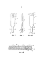
ФИГ. 1А иллюстрирует изображение в перспективе примерной тестовой полоски;FIG. 1A illustrates a perspective view of an exemplary test strip;
ФИГ. 1В иллюстрирует изображение в перспективе с пространственным разделением деталей тестовой полоски с ФИГ. 1А;FIG. 1B illustrates an exploded perspective view of the test strip of FIG. 1A;
ФИГ. 1С иллюстрирует изображение в перспективе дистальной части тестовой полоски с ФИГ. 1А;FIG. 1C illustrates a perspective view of the distal portion of the test strip of FIG. 1A;
ФИГ. 2 иллюстрирует вид снизу тестовой полоски с ФИГ. 1А;FIG. 2 illustrates a bottom view of the test strip of FIG. 1A;
ФИГ. 3 иллюстрирует вид сбоку тестовой полоски с ФИГ. 1А;FIG. 3 illustrates a side view of the test strip of FIG. 1A;
ФИГ. 4А иллюстрирует вид сверху тестовой полоски с ФИГ. 1А;FIG. 4A illustrates a top view of the test strip of FIG. 1A;
ФИГ. 4В иллюстрирует частичный вид сбоку дистальной части тестовой полоски, согласующийся со стрелками 4В-4В на ФИГ. 4А;FIG. 4B illustrates a partial side view of the distal portion of the test strip, consistent with
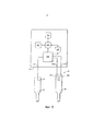
ФИГ. 5 иллюстрирует упрощенную схему, показывающую тестер, электрически сопрягающийся с контактными площадками тестовой полоски;FIG. 5 illustrates a simplified diagram showing a tester electrically mating with the pads of a test strip;
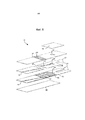
ФИГ. 6 иллюстрирует вид с пространственным разделением деталей примерного варианта реализации иммуносенсора в соответствии с настоящим изобретением;FIG. 6 illustrates an exploded view of an exemplary embodiment of an immunosensor in accordance with the present invention;
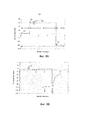
ФИГ. 7А иллюстрирует форму сигнала тестового напряжения, с которой тестер прикладывает множество тестовых напряжений в течение предписанных интервалов времени;FIG. 7A illustrates a test voltage waveform with which a tester applies a plurality of test voltages over prescribed time intervals;
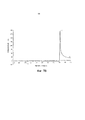
ФИГ. 7В иллюстрирует транзиент тестового тока, сгенерированного с формой сигнала тестового напряжения по ФИГ. 6;FIG. 7B illustrates the transient of the test current generated with the test voltage waveform of FIG. 6;
ФИГ. 8А иллюстрирует форму сигнала тестового напряжения, с которой тестер прикладывает множество тестовых напряжений при противоположной полярности в течение предписанных интервалов времени по сравнению с ФИГ. 7А;FIG. 8A illustrates a test voltage waveform with which a tester applies a plurality of test voltages at opposite polarity for prescribed time intervals compared to FIG. 7A;
ФИГ. 8В иллюстрирует транзиент тестового тока, сгенерированного с тестовыми напряжениями по ФИГ. 8А;FIG. 8B illustrates the transient of the test current generated with the test voltages of FIG. 8A;
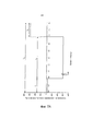
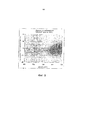
ФИГ. 9 - это график, на котором показана взаимосвязь между емкостью и процентной долей смещения для множества тестов.FIG. 9 is a graph showing the relationship between capacity and percentage bias for a plurality of tests.
ПОДРОБНОЕ ОПИСАНИЕDETAILED DESCRIPTION
Следующее подробное описание следует читать с обращением к чертежам, на которых аналогичные элементы на различных чертежах пронумерованы одинаково. Чертежи, не требующие масштабирования, изображают избранные варианты реализации и не предназначены ограничивать объем изобретения. Подробное описание иллюстрирует в качестве примера, а не ограничения, принципы изобретения.The following detailed description should be read with reference to the drawings, in which like elements in different drawings are numbered the same. Drawings that do not require scaling depict selected implementations and are not intended to limit the scope of the invention. The detailed description illustrates, by way of example, and not limitation, the principles of the invention.
Использованные здесь термины "примерно" или "приблизительно" для любых численных значений или диапазонов указывают на подходящее допустимое отклонение величины, позволяющее детали или набору компонентов функционировать по своему назначению, как описано ниже. Кроме того, использованные здесь термины "пациент", "реципиент", "пользователь" и "объект" относятся к любому объекту - человеку или животному и не предназначены ограничиваться системами или способами для применения в отношении человека, хотя применение данного изобретения в отношении пациента-человека представляет собой предпочтительный вариант реализации.As used herein, the terms “about” or “approximately” for any numerical values or ranges indicate a suitable tolerance for the quantity to allow the part or set of components to function as intended, as described below. In addition, the terms “patient”, “recipient”, “user” and “object” as used herein refer to any object — a human or animal, and are not intended to be limited to systems or methods for use in relation to a human being, although the application of the present invention to a patient is human is a preferred implementation option.
Далее будут описаны некоторые примерные варианты реализации, дающие общее представление о принципах конструкции, функционировании, изготовлении и применении обсуждаемых далее систем и способов. Один и более из примеров этих вариантов реализации показаны на сопроводительных чертежах. Специалисты поймут, что системы и способы, особо описанные далее и показанные на прилагаемых чертежах, представляют собой неограничивающие примерные варианты реализации и что объем настоящего изобретения определяется исключительно формулой изобретения. Признаки, проиллюстрированные или описанные в связи с одним примерным вариантом реализации, могут быть скомбинированы с признаками других вариантов реализации. Предполагается, что такие изменения и вариации входят в объем настоящего изобретения.Next, some exemplary embodiments will be described that give a general idea of the principles of design, operation, manufacture and application of the systems and methods discussed below. One or more examples of these embodiments are shown in the accompanying drawings. Those skilled in the art will understand that the systems and methods specifically described below and shown in the accompanying drawings are non-limiting exemplary embodiments and that the scope of the present invention is defined solely by the claims. The features illustrated or described in connection with one exemplary embodiment may be combined with the features of other embodiments. It is assumed that such changes and variations are included in the scope of the present invention.
Описанные здесь системы и способы пригодны для применения при определении широкого спектра аналитов в широком спектре образцов и особенно пригодны для определения аналитов в цельной крови, плазме, сыворотке, межклеточной жидкости или их производных. В примерном варианте реализации система теста на глюкозу на основе тонкослойной ячейки с противоположными электродами и трехимпульсным быстрым электрохимическим детектированием (например, время анализа примерно 5 секунд) требует небольшого образца (например, примерно 0,4 мкл) и может обеспечить повышенную надежность и точность измерений уровня глюкозы в крови. В реакционной ячейке для анализа аналита глюкозу в образце может быть окислена до глюконолактона при помощи глюкозодегидрогеназы, и при этом может быть использован электрохимически активный медиатор для переноса электронов от этого фермента к палладиевому рабочему электроду. Конкретнее, покрытие из слоя реагента по меньшей мере одного из электродов в реакционной ячейке может включать глюкозодегидрогеназу (GDH) в присутствии кофактора пирролохинолинхинона (PQQ) и феррицианида. В другом варианте реализации фермент GDH в присутствии кофактора PQQ можно заменить на фермент GDH в присутствии кофактора флавинадениндинуклеотида (FAD). При добавлении в реакционную камеру крови или контрольного раствора глюкоза окисляется под действием 60Н(окисл.), и в этом процессе происходит превращение CDH(окисл.) в GDH(bocct.), как показано в химической реакции Т.1 ниже. Отметим, что CDH(окисл.) относится к окисленному состоянию GDH, a GDH(восст.) относится к восстановленному состоянию GDH.The systems and methods described herein are suitable for use in determining a wide range of analytes in a wide range of samples and are particularly suitable for determining analytes in whole blood, plasma, serum, intercellular fluid or their derivatives. In an exemplary embodiment, a thin layer cell glucose test system with opposing electrodes and three-pulse fast electrochemical detection (e.g., analysis time of about 5 seconds) requires a small sample (e.g., approximately 0.4 μl) and can provide increased reliability and accuracy of level measurements blood glucose. In the reaction cell for analysis of the analyte, glucose in the sample can be oxidized to gluconolactone using glucose dehydrogenase, and an electrochemically active mediator can be used to transfer electrons from this enzyme to the palladium working electrode. More specifically, the coating from the reagent layer of at least one of the electrodes in the reaction cell may include glucose dehydrogenase (GDH) in the presence of cofactor pyrroloquinolinequinone (PQQ) and ferricyanide. In another embodiment, the GDH enzyme in the presence of the PQQ cofactor can be replaced by the GDH enzyme in the presence of the cofactor flavin adenine dinucleotide (FAD). When blood or a control solution is added to the reaction chamber, glucose is oxidized under the influence of 60H (oxid.), And in this process the conversion of CDH (oxid.) To GDH (bocct.) Occurs, as shown in chemical reaction T.1 below. Note that CDH (oxidation) refers to the oxidized state of GDH, while GDH (reduction) refers to the reduced state of GDH.
Т.1 D-глюкоза+GDH(окисл.)→глюконовая кислота+GDH (восст.)T.1 D-glucose + GDH (oxid.) → gluconic acid + GDH (rest.)
Можно использовать потенциостат для приложения трехимпульсного сигнала напряжения между рабочим электродом и противоэлектродом, что приводит к появлению транзиентов тестового тока, используемых для расчета концентрации глюкозы. Затем дополнительную информацию, полученную из транзиентов тестового тока, можно использовать для распознавания матриц образцов и поправки на изменчивость в образцах крови из-за гематокрита, колебания температуры, электрохимически активных компонентов, а также выявления возможных системных ошибок.You can use the potentiostat to apply a three-pulse voltage signal between the working electrode and the counter electrode, which leads to the appearance of test current transients used to calculate the glucose concentration. Then, additional information obtained from test current transients can be used to recognize sample matrices and correct for variability in blood samples due to hematocrit, temperature fluctuations, electrochemically active components, as well as the identification of possible system errors.
Данные способы можно, в принципе, применять в случае любого типа электрохимической ячейки с разнесенными первым и вторым электродами и слоем реагента. Например, электрохимическая ячейка может быть в виде тестовой полоски. В одном аспекте тестовая полоска может включать два противоположных электрода, разделенных тонкой прокладкой для ограничения принимающей образец камеры или зоны, в которой расположен слой реагента. Заявители отмечают, что с описанными здесь способами можно также использовать другие типы тестовых полосок, включая, например, тестовые полоски с копланарными электродами.These methods can, in principle, be applied to any type of electrochemical cell with spaced first and second electrodes and a reagent layer. For example, the electrochemical cell may be in the form of a test strip. In one aspect, the test strip may include two opposing electrodes separated by a thin spacer to limit the sample receiving chamber or area in which the reagent layer is located. Applicants note that other types of test strips can also be used with the methods described herein, including, for example, test strips with coplanar electrodes.
Электрохимические ячейкиElectrochemical cells
На ФИГ. 1А-4В показаны различные виды примерной тестовой полоски 62, пригодной для применения с описанными здесь способами. Как показано, тестовая полоска 62 может включать продолговатое тело, простирающееся от проксимального конца 80 до дистального конца 82, с боковыми краями 56, 58. Проксимальная часть тела 59 может включать реакционную камеру 61 для образца с несколькими электродами 164, 166 и реагентом 72, тогда как дистальная часть тела 59 тестовой полоски может включать элементы для обеспечения электрической связи с тестером. При эксплуатации в реакционную камеру 61 для образца вводят физиологическую жидкость или контрольный раствор для электрохимического анализа.In FIG. 1A-4B show various views of an
В показанном варианте реализации тестовая полоска 62 может включать первый электродный слой 66 и второй электродный слой 64 с расположенным между ними слоем 60 прокладки. Первый электродный слой 66 может обеспечивать первый электрод 166 и первую соединительную дорожку 76 для электрического соединения первого электрода 166 с первым электрическим контактом 67. Аналогично, второй электродный слой 64 может обеспечивать второй электрод 164 и вторую соединительную дорожку 78 для электрического соединения второго электрода 164 со вторым электрическим контактом 63.In the shown embodiment, the
В одном варианте реализации реакционная камера 61 для образца ограничена первым электродом 166, вторым электродом 164 и прокладкой 60, как показано на ФИГ. 1А-4В. Точнее, первый электрод 166 и второй электрод 164 образуют, соответственно, дно и верх реакционной камеры 61 для образца. Вырез 68 прокладки 60 может образовывать боковые стенки реакционной камеры 61 для образца. В одном аспекте реакционная камера 61 для образца может дополнительно включать ряд отверстий 70, которые обеспечивают вход образца и/или вентиляционное отверстие. Например, одно из отверстий может обеспечивать поступление жидкого образца, а другое отверстие может действовать как вентиляционное отверстие.In one embodiment, the
Реакционная камера 61 для образца может иметь малый объем. Например, объем может составлять от примерно 0,1 микролитра до примерно 5 микролитров, предпочтительно от примерно 0,2 микролитра до примерно 3 микролитров, а еще более предпочтительно от примерно 0,3 микролитра до примерно 1 микролитра. Как будет понятно специалистам, реакционная камера 61 для образца может иметь различные другие такие объемы. Для обеспечения, малого объема образца вырез 68 может иметь площадь в диапазоне от примерно 0,01 см2 до примерно 0,2 см2, предпочтительно от примерно 0,02 см2 до примерно 0,15 см2, а еще более предпочтительно от примерно 0,03 см2 до примерно 0,08 см2. Аналогично, специалистам будет понятно, что объемный вырез 68 может иметь разные другие такие площади. Кроме того, первый и второй электроды 166, 164 могут отстоять друг от друга на расстояние от примерно 1 микрона до примерно 500 микрон, предпочтительно в диапазоне от примерно 10 микрон до примерно 400 микрон, а еще более предпочтительно в диапазоне от примерно 40 микрон до примерно 200 микрон. В других вариантах реализации такой диапазон может колебаться между различными другими значениями. Близкое расположение электродов может также обеспечивать возможность окислительно-восстановительного циклирования, при котором окисленный медиатор, образовавшийся на первом электроде 166, может диффундировать ко второму электроду 164, чтобы восстанавливаться, а затем диффундировать обратно к первому электроду 166, чтобы вновь окисляться.The
На дистальном конце тела 59 тестовой полоски первый электрический контакт 67 можно использовать для установления электрического соединения с тестером. Доступ тестера ко второму электрическому контакту 63 можно обеспечить через U-образную прорезь 65, как показано на ФИГ. 2. Заявители отмечают, что тестовая полоска 62 может содержать ряд альтернативных электрических контактов, предназначенных для обеспечения электрического соединения с тестером. Например, патент США №6379513, все содержание которого настоящим включено сюда по ссылке, описывает средства подсоединения электрохимической ячейки.At the distal end of the
В одном варианте реализации первый электродный слой 66 и/или второй электродный слой 64 могут представлять собой проводящий материал, образованный из таких материалов, как золото, палладий, углерод, серебро, платина, оксид олова, иридий, индий и их сочетания (например, легированный индием оксид олова). Кроме того, электроды можно сформировать путем нанесения проводящего материала на изолирующий лист (не показан) при помощи различных технологий, таких как, например, напыление, нанесение покрытия методом химического восстановления или трафаретная печать. В одном примерном варианте реализации второй электродный слой 64 может представлять собой напыленный золотой электрод, а первый электродный слой 66 может представлять собой напыленный палладиевый электрод. Подходящие материалы, которые можно использовать в качестве слоя 60 прокладки, включают различные изоляторы, такие как, например, пластики (например, ПЭТ, ПЭТГ, полиимид, поликарбонат, полистирол), кремний, керамика, стекло, клеи и их сочетания.In one embodiment, the
Слой реагента 72 можно нанести внутри реакционной камеры 61 для образца при помощи таких технологий, как щелевое нанесение, нанесение с подачей из конца трубки, нанесение чернилами и трафаретная печать. Такие технологии описаны, например, в следующих патентах США №№: 6749887, 6869411, 6676995, и 6830934, каждый из которых целиком включен сюда по ссылке. В одном из вариантов реализации слой реагента 72 может включать, по меньшей мере, медиатор и фермент и может быть осажден на первый электрод 166. В пределы сути и объема данного изобретения попадают различные медиаторы и/или ферменты. Например, подходящие медиаторы включают феррицианид, ферроцен, производные ферроцена, комплексы бипиридилосмия и производные хинона. Примеры подходящих ферментов включают глюкозооксидазу, глюкозодегидрогеназу (GDH) в присутствии кофактора пирролохинолинхинона (PQQ), GDH в присутствии кофактора никотинамидадениндинуклеотида и GDH в присутствии кофактора флавинадениндинуклеотида [Е.С.1.1.99.10]. Один из примерных составов реагентов, пригодный для формирования слоя реагента 72, описан в совместно поданной заявке на патент США №10/242951, озаглавленной: "Способ производства стерилизованного и калиброванного биосенсорного медицинского устройства", опубликованной под номером публикации заявки на патент США № 2004/0120848, которая настоящим целиком включена сюда по ссылке.The
Либо первый электрод 166, либо второй электрод 164 могут функционировать как рабочий электрод, окисляющий или восстанавливающий лимитирующее количество медиатора в зависимости от полярности приложенного тестового потенциала тестера. Например, если лимитирующее ток вещество представляет собой восстановленный медиатор, то оно может окисляться на первом электроде 166, пока к нему приложен достаточно положительный потенциал по отношению ко второму электроду 164. В такой ситуации первый электрод 166 выполняет функцию рабочего электрода, а второй электрод 164 выполняет функцию противоэлектрода/электрода сравнения. Следует отметить, что если не указано иное для тестовой полоски 62, все потенциалы, приложенные тестером 100, будут далее указаны в отношении второго электрода 164.Either the
Аналогично, если приложен достаточно отрицательный потенциал по отношению ко второму электроду 164, то восстановленный медиатор может окисляться на втором электроде 164. В такой ситуации второй электрод 164 выполняет функцию рабочего электрода, а первый электрод 166 выполняет функцию противоэлектрода/электрода сравнения.Similarly, if a sufficiently negative potential is applied with respect to the
Изначально предлагаемый способ может включать введение некоторого количества представляющего интерес жидкого образца в тестовую полоску 62, которая имеет первый электрод 166, второй электрод 164 и слой реагента 72. Жидкий образец может представлять собой цельную кровь или ее производную или фракцию, или же контрольный раствор. Жидкий образец, например, кровь, можно ввести в реакционную камеру 61 для образца через отверстие 70. В одном аспекте отверстие 70 и/или реакционная камера 61 для образца могут быть сконструированы так, что действие капиллярных сил заставляет жидкий образец заполнять реакционную камеру 61 для образца.Initially, the proposed method may include introducing a certain amount of a liquid sample of interest into the
На ФИГ. 5 показана упрощенная схема тестера 100, сопрягающегося с первым электрическим контактом 67 и вторым электрическим контактом 63, которые электрически связаны соответственно с первым электродом 166 и вторым электродом 164 тестовой полоски 62. Тестер 100 может быть выполнен с возможностью электрического соединения с первым электродом 166 и вторым электродом 164 через первый электрический контакт 67 и второй электрический контакт 63 соответственно (как показано на ФИГ. 2 и 5). Как будет понятно специалистам, в описанном здесь способе можно использовать множество различных тестеров. Однако в одном варианте реализации тестер включает в себя по меньшей мере процессор, который может включать в себя один или более блоков управления, предназначенных для выполнения расчетов, позволяющих вычислять поправочный коэффициент с учетом по меньшей мере одного измеряемого параметра, коррелирующего с физическим свойством электрохимической ячейки, а также предназначенных для сортировки и/или хранения данных. Микропроцессор может быть в виде процессора смешанного типа (MSP), т.е. аналого-цифрового, такого как, например, Texas Instrument MSP 430. TI-MSP 430 может быть также предназначен выполнять часть функции потенциостата и функции измерения тока. Кроме того, MSP 430 также может включать в себя энергозависимую и долговременную память. В другом варианте реализации многие из электронных компонентов могут быть интегрированы с микроконтроллером в виде специализированной интегральной схемы.In FIG. 5 shows a simplified diagram of a
Как показано на ФИГ. 5, электрический контакт 67 может включать в себя два штыря 67а, 67b. В одном примерном варианте реализации тестер 100 отдельно соединяется со штырями 67а, 67b так, чтобы при сопряжении тестера 100 с тестовой полоской 62 цепь замыкалась. Тестер 100 может измерять сопротивление или неразрывность электрической цепи между штырями 67а, 67b, чтобы определить, наличествует ли электрическое подключение между тестовой полоской 62 и тестером 100. Заявители отмечают, что тестер 100 может использовать множество различных сенсоров и цепей для определения того, правильно ли расположена тестовая полоска 62 по отношению к тестеру 100.As shown in FIG. 5, the
В одном варианте реализации цепь, расположенная в тестере 100, может прикладывать тестовый потенциал и/или ток между первым электрическим контактом 67 и вторым электрическим контактом 63. Как только тестер 100 выявляет, что была вставлена полоска 62, тестер 100 включается и запускает режим обнаружения жидкости. В одном варианте реализации режим обнаружения жидкости вынуждает тестер 100 подавать постоянный ток в 1 микроампер между первым электродом 166 и вторым электродом 164. Поскольку тестовая полоска 62 изначально сухая, тестер 100 измеряет максимальное напряжение, которое ограничено аппаратными средствами в тестере 100. Однако как только пользователь вводит жидкий образец во входное отверстие 70, это приводит к заполнению реакционной камеры 61 для образца. Когда жидкий образец заполняет промежуток между первым электродом 166 и вторым электродом 164, тестер 100 измеряет уменьшение измеренного напряжения (например, как описано в патенте США №6193873, который целиком включен сюда по ссылке), которое ниже заданного порога, что заставляет тестер 100 автоматически начинать тест на глюкозу.In one embodiment, the circuit located in the
Следует отметить, что измеренное напряжение может уменьшаться ниже заданного порога, когда заполнена только некая доля реакционной камеры 61 для образца. Способ автоматического выявления того, что жидкость нанесена, не обязательно позволяет установить, что реакционная камера 61 для образца целиком заполнена, и может только подтвердить наличие некоторого количества жидкости в реакционной камере 61 для образца. Как только тестер 100 определяет, что на тестовую полоску 62 нанесена жидкость, может потребоваться еще небольшое, но ненулевое количество времени для того, чтобы позволить жидкости целиком заполнить реакционную камеру 61 для образца.It should be noted that the measured voltage can decrease below a predetermined threshold when only a certain fraction of the
Другой примерный вариант реализации устройства для анализа образца для применения в сочетании с по меньшей мере некоторыми из описанных здесь способов, иммуносенсор 110, показан на ФИГ. 6 и описан в заявке на патент США с порядковым №12/570268 авторов Chatelier и др., озаглавленной "Адгезивные составы для применения в иммуносенсоре" и поданной 30 сентября 2009 г., содержимое которой целиком включено сюда по ссылке. В иммуносенсоре может быть образовано множество камер, включая камеру заполнения, через которую образец может быть введен в иммуносенсор, реакционную камеру, в которой образец может прореагировать с одним и более желательными материалами, и камеру детектирования, при помощи которой можно определить концентрацию конкретного компонента образца. Эти камеры могут быть сформированы в по меньшей мере части первого электрода, второго электрода и сепаратора имммуносенсора. Иммуносенсор может также иметь вентиляционное отверстие, позволяющее воздуху входить в иммуносенсор и выходить из него по мере необходимости, и первую и вторую герметизирующие детали для селективной герметизации первой и второй сторон вентиляционного отверстия. Первая герметизирующая деталь также может образовывать стенку камеры заполнения.Another exemplary embodiment of a device for analyzing a sample for use in combination with at least some of the methods described herein, an
Как показано, иммуносенсор 110 включает в себя первый электрод 112 с двумя нанесенными на него полосками жидких реагентов 130, 132. Первый электрод 112 может быть сформирован с применением любого числа методик, используемых для формирования электродов, но в одном варианте реализации на лист полиэтилентерефталата (ПЭТ), наполненный сульфатом бария, напыляют золото методом ионного распыления. Лист ПЭТ также может быть наполнен диоксидом титана. Другой неограничивающий пример формирования электрода раскрыт в патенте США №6521110 авторов Ходжеса и др., озаглавленном "Электрохимическая ячейка", с датой подачи 10 ноября 2000 г., содержимое которого целиком включено сюда по ссылке.As shown, the
Аналогично, жидкие реагенты 130, 132 могут иметь ряд различных составов. В одном варианте реализации первый жидкий реагент 130 включает антитело, сопряженное с ферментом, такое как GDH-PQQ, в буферном растворе, содержащем сахарозу, а также полоксамер, такой как блок-сополимеры Pluronics®, антикоагулянт, такой как цитраконат, и ионы кальция. В одном варианте реализации второй жидкий реагент 132 включает смесь феррицианида, глюкозы и второго медиатора, такого как феназинэтосульфат, в кислом буферном растворе, таком как разбавленный раствор цитраконовой кислоты. Первый и второй жидкие реагенты 130, 132 могут быть высушены на первом электроде 112. Ряд методик можно использовать для сушки реагентов 130, 132, но в одном варианте реализации после нанесения полосок реагентов 130, 132 на первый электрод 112 в отношении реагентов 130, 132 могут быть использованы одна и более инфракрасных (ИК) сушилок. Можно также использовать одну и более воздушных сушилок, например, после ИК-сушилок. Ссылки на первый реагент и первый жидкий реагент и второй реагент и второй жидкий реагент в настоящем документе взаимозаменяемы и необязательно являются указанием на то, что реагенты находятся в их жидкой или сухой форме в данное время в данном конкретном варианте реализации. Далее, некоторые из компонентов, ассоциированных с первым и вторым жидкими реагентами, можно использовать взаимозаменяемо и/или в обоих, первом и втором, жидких реагентах, по желанию. В качестве неограничивающего примера, антикоагулянт можно ассоциировать с любым из первого жидкого реагента 130 и второго жидкого реагента 132 или ими обоими.Similarly,
На напыленном золоте между реагентами 130, 132 можно сформировать линию так, что край реагента 132 находится очень близко к линии или соприкасается с ней. Линию можно нанести путем лазерного выжигания или при помощи металлического острия. В одном примерном варианте реализации линию можно сформировать до того, как полоски реагентов 130, 132 нанесены на электрод. Линия может быть предназначена для электрической изоляции области первого электрода 112 под камерой детектирования от области, которая будет под реакционной камерой. Это может обеспечить лучшее определение площади рабочего электрода во время электрохимического анализа.On the sprayed gold between the
Иммуносенсор 110 также может включать в себя второй электрод 114 с одним или более магнитными бусинками 134, содержащими поверхностно-связанные на них антигены. Антигены можно подобрать так, чтобы они реагировали с антителом, расположенным на первом электроде 112, и образцом внутри реакционной камеры 118, как подробно описано далее. Специалист согласится, что компоненты, расположенные на первом электроде 112 и на втором электроде 114, могут быть взаимозаменяемыми. Таким образом, первый электрод 112 может включать один и более магнитных бусинок 134, а второй электрод 114 может включать две нанесенные на него полоски жидких реагентов 130, 132. Далее, хотя в описанном варианте реализации длина электрода 112 соответствует всей длине всего тела иммуносенсора 110, в других вариантах реализации электрод может представлять собой только часть слоя иммуносенсора, которая служит первым или вторым электродами, или же множественные электроды могут быть расположены на одном слое иммуносенсора. Кроме того, поскольку приложенное к иммуносенсору напряжение можно поменять на обратное или сделать переменным, каждый из первого и второго электродов может на разных стадиях служить и рабочим электродом, и противоэлектродом или противоэлектродом сравнения. Для простоты описания в настоящей заявке первый электрод рассматривается как рабочий электрод, а второй электрод - как противоэлектрод или противоэлектрод сравнения.The
Сепаратор 116, расположенный между первым и вторым электродами 112, 114, может иметь множество различных форм и размеров, но обычно он сконфигурирован так, чтобы желательным образом соприкасаться с первым и вторым электродами 112, 114, образуя иммуносенсор 110. В одном примерном варианте реализации сепаратор 116 содержит клей на обеих сторонах. Сепаратор 116 может дополнительно включать антиадгезионный материал с каждой из двух сторон сепаратора 116. Сепаратор 116 может быть вырезан таким образом, что образует по меньшей мере две полости. Первая полость может быть образована так, чтобы служить реакционной камерой 118, а вторая полость - камерой 120 детектирования. В одном варианте реализации сепаратор 116 может быть надсечен так, чтобы реакционная камера 118 была совмещена с электродами 112, 114, позволяя проходить в ней реакции антиген-антитело, а камера 120 детектирования была совмещена с электродами 112, 114, обеспечивая возможность электрохимического определения в ней ферроцианида.The separator 116, located between the first and
В одном варианте реализации сепаратор 116 можно поместить на первый электрод 112 таким образом, который позволяет магнитным бусинкам 134 второго электрода 114 и первому реагенту 130 первого электрода 112 быть по меньшей мере частично расположенными в реакционной камере 118, а сочетанию феррицианид-глюкоза второго реагента 132 первого электрода 112 быть по меньшей мере частично расположенным в камере 120 детектирования. Может быть полезно включить антикоагулянт и в первый, и во второй жидкие реагенты 130, 132 с тем, чтобы антикоагулянт был ассоциирован и с реакционной камерой 118, и с камерой 120 детектирования. В некоторых вариантах реализации сочетание одного из первого и второго электродов 112, 114 и сепаратора 116 можно ламинировать вместе с образованием двухслойного ламината, тогда как в других вариантах реализации можно ламинировать вместе сочетание каждого из первого электрода 112, второго электрода 114 и сепаратора 116 с образованием трехслойного ламината. Альтернативно, можно также добавить дополнительные слои.In one embodiment, the separator 116 can be placed on the
Камера 122 заполнения может быть сформирована путем пробивания отверстия в одном из первого и второго электродов 112, 114 и сепараторе 116. В показанном варианте реализации камера заполнения сформирована путем пробивания отверстия в первом электроде 112 и сепараторе 116 так, чтобы отверстие в первом электроде 112 перекрывалось с реакционной камерой 118. Как показано, камера 122 заполнения может находиться на расстоянии от камеры 120 детектирования. Такая конфигурация позволяет образцу входить в иммуносенсор 110 через камеру 122 заполнения и протекать в реакционную камеру 118, чтобы там прореагировать, например, с первым жидким реагентом 130, включающим антитело, сопряженное с ферментом в буферном растворе на первом электроде 112, и магнитными бусинками 134, нанесенными полосками на второй электрод 114, без попадания в камеру 120 детектирования. После того, как образец прореагировал, он может затекать в камеру 120 детектирования, претерпевая химическое или физическое превращение со вторым реагентом 132, например, смесью феррицианида, глюкозы и второго медиатора в кислом буферном растворе.The filling
Вентиляционное отверстие 124 может быть сформировано путем пробивания отверстия через каждый из двух электродов 112, 114 и сепаратор 116 так, чтобы вентиляционное отверстие 124 проходило через весь иммуносенсор 110. Отверстие может быть сформировано любым подходящим образом, например, просверлено или пробито в нескольких различных местах, но в одном примерном варианте реализации оно может перекрываться с областью камеры 120 детектирования, которая расположена отдельно от реакционной камеры 118.A
Вентиляционное отверстие 124 можно герметизировать несколькими различными способами. В показанном варианте реализации первая герметизирующая деталь 140 расположена на первом электроде 112 для герметизации первой стороны вентиляционного отверстия 124, а вторая герметизирующая деталь 142 расположена на втором электроде 114 для герметизации второй стороны вентиляционного отверстия 124. Герметизирующие детали могут быть изготовлены из любого числа материалов и/или могут включать любое число материалов. В качестве неограничивающего примера, любая из герметизирующих деталей или они обе могут представлять собой гидрофильную липкую ленту или клейкую ленту Scotch®. Клейкие стороны герметизирующих деталей могут быть обращены к иммуносенсору 110. Как показано, первая герметизирующая деталь 140 может не только формировать уплотнение вентиляционного отверстия 124, но и образовывать стенку камеры 122 заполнения так, чтобы в ней мог содержаться образец. Свойства, реализованные на клейкой стороне первой герметизирующей детали 140, могут быть связаны с камерой 122 заполнения. Например, если первая герметизирующая деталь 140 имеет свойства, делающие ее гидрофильной и/или водорастворимой, камера заполнения может оставаться хорошо смоченной, когда в ней расположен образец. Далее, герметизирующие детали 140, 142 могут селективно связываться с иммуносенсором 110 или разъединяться с ним, обеспечивая по мере необходимости вентиляцию и/или герметизацию иммуносенсора 110 и расположенных в нем деталей.Vent 124 may be sealed in several different ways. In the shown embodiment, the
В конструкции иммуносенсора, как правило, можно использовать клейкие вещества. Неограничивающие примеры способов, которыми клейкие вещества могут быть включены в состав иммуносенсоров и других устройств для анализа образца по настоящему изобретению, можно найти в заявке на патент США с порядковым №12/570268 авторов Chatelier и др., озаглавленной "Клейкие составы для применения в иммуносенсоре", поданной 30 сентября 2009 г., содержимое которой уже было целиком включено сюда по ссылке.In the construction of the immunosensor, as a rule, sticky substances can be used. Non-limiting examples of the ways in which adhesives can be incorporated into immunosensors and other sample analysis devices of the present invention can be found in US Patent Application Serial No. 12/570268 by Chatelier et al., Entitled “Adhesives for Use in an Immunosensor "filed September 30, 2009, the entire contents of which were hereby incorporated by reference in their entirety.
В то время как в настоящем документе обсуждается ряд различных вариантов реализации, относящихся к иммуносенсорам, другие варианты реализации иммуносенсоров также можно использовать со способами по настоящему изобретению. Неограничивающие примеры таких вариантов реализации включают описанные в публикации заявки на патент США №2003/0180814 авторов Ходжеса и др., озаглавленной "Прямой иммуносенсорный анализ" и поданной 21 марта 2002 г., публикации заявки на патент While a number of different implementations related to immunosensors are discussed herein, other implementations of immunosensors can also be used with the methods of the present invention. Non-limiting examples of such embodiments include those described in US Patent Application Publication No. 2003/0180814 by Hodges et al, entitled "Direct Immunosensory Assay" and filed March 21, 2002, patent application publication
США №2004/0203137 авторов Ходжеса и др., озаглавленной "Иммуносенсор" и поданной 22 апреля 2004 г., публикации заявки на патент США №2006/0134713 авторов Rylatt и др., озаглавленной "Биосенсорное устройство и способы применения" и поданной 21 ноября 2005 г., и заявке на патент США с порядковым №12/563091, которая испрашивает приоритет по каждой из публикаций заявок на патент США №№2003/0180814 и 2004/0203137, каждая из которых целиком включена сюда по ссылке.US No. 2004/0203137 by Hodges et al. Entitled "Immunosensor" and filed April 22, 2004, publication of US patent application No. 2006/0134713 by Rylatt et al., Entitled "Biosensor device and methods of application" and filed November 21 2005, and US Patent Application Serial No. 12/563091, which claims priority for each of the publication of US patent applications No. 2003/0180814 and 2004/0203137, each of which is incorporated herein by reference in its entirety.
В одном варианте реализации иммуносенсор 110 может быть выполнен с возможностью размещения в измерительном приборе, который выполнен с возможностью, например, через подходящую цепь (схему), подавать потенциал на электроды 112, 114 и измерять ток, возникающий в результате подачи потенциала. В одном варианте реализации иммуносенсор включает в себя один или более выводов 117 для взаимодействия с измерительным прибором. Также можно использовать другие признаки для взаимодействия иммуносенсора 110 с измерительным прибором. Измерительный прибор может иметь ряд различных признаков. Например, измерительный прибор может включать в себя магнит, который выполнен с возможностью удерживать определенные компоненты иммуносенсора 110 в одной камере, тогда как другие перетекают в другую. В одном примерном варианте реализации магнит измерительного прибора расположен так, что, при помещении иммуносенсора 110 в измерительный прибор, магнит расположен ниже реакционной камеры 118. Это может позволить магниту содействовать удерживанию любых магнитных бусинок 134 и, в частности, любого конъюгата антитело-фермент, который связан с бусинками 134, от попадания в камеру 120 детектирования.In one embodiment, the implementation of the
Альтернативный признак измерительного прибора включает нагревательный элемент.Нагревательный элемент может способствовать ускорению реакции и содействовать протеканию образца через иммуносенсор 110 желательным образом за счет снижения вязкости. Нагревательный элемент может также позволять нагревать одну или более камер и/или расположенный в ней/них образец до заданной температуры. Нагрев до заданной температуры может помочь обеспечить точность, например, за счет снижения или устранения влияния изменений температуры по мере протекания реакций.An alternative feature of the meter includes a heating element. The heating element can help accelerate the reaction and facilitate the flow of the sample through the
Далее, с измерительным прибором может быть также ассоциирован колющий инструмент. Колющий инструмент может быть выполнен с возможностью прокалывать по меньшей мере одну из первой и второй герметизирующих деталей в желаемое время с тем, чтобы воздух мог вытекать из вентиляционного отверстия, а жидкость могла протекать из реакционной камеры в камеру детектирования.Further, a pricking tool may also be associated with the meter. The pricking tool may be configured to pierce at least one of the first and second sealing parts at a desired time so that air can flow out of the vent and the liquid can flow from the reaction chamber into the detection chamber.
Иммуносенсор 110 и тестовая полоска 62 могут также быть выполнены с возможностью связываться с блоком управления. Блок управления может быть выполнен с возможностью выполнять ряд различных функций. В одном примерном варианте реализации блок управления способен измерять время заполнения образцом при его введении в устройство. В другом варианте реализации блок управления может быть выполнен с возможностью определять значение гематокрита образца крови. В еще одном варианте реализации блок управления быть выполнен с возможностью рассчитывать концентрацию аналита в образце с учетом времени заполнения. Фактически, блок управления может иметь ряд различных признаков, зависящих, по меньшей мере отчасти, от желательной функциональности и того способа, которым система предназначена измерять время заполнения.The
Блок управления также может измерять другие аспекты системы. В качестве неограничивающего примера, блок управления может быть выполнен с возможностью измерять температуру одной или более камер иммуносенсора или тестовой полоски. Он также может быть выполнен с возможностью измерять температуру образца, цвет образца, емкость иммуносенсора или тестовой полоски или ряд различных других характеристик и/или свойств образца и/или системы. В качестве еще одного неограничивающего примера, блок управления может быть выполнен с возможностью передавать результаты определения времени заполнения, результаты измерения емкости, результаты определения концентрации аналита и/или измерения гематокрита на внешнее оборудование. Это может быть осуществлено при помощи ряда способов. В одном варианте реализации блок управления может быть соединен кабелем с микропроцессором и/или устройством отображения. В другом варианте реализации блок управления может быть выполнен с возможностью передавать при помощи беспроводной связи данные от блока управления микропроцессору и/или устройству отображения.The control unit can also measure other aspects of the system. By way of non-limiting example, the control unit may be configured to measure the temperature of one or more chambers of the immunosensor or test strip. It can also be configured to measure the temperature of the sample, the color of the sample, the capacitance of the immunosensor or test strip, or a number of different other characteristics and / or properties of the sample and / or system. As another non-limiting example, the control unit may be configured to transmit the results of determining the filling time, the results of measuring the capacitance, the results of determining the concentration of analyte and / or measuring the hematocrit to external equipment. This can be done in a number of ways. In one embodiment, the control unit may be cabled to a microprocessor and / or display device. In another embodiment, the control unit may be configured to wirelessly transmit data from the control unit to the microprocessor and / or display device.
Другие компоненты системы также могут быть выполнены с возможностью проводить такие измерения. Например, иммуносенсор или измерительный прибор может быть выполнен с возможностью измерять температуру одной или более камер иммуносенсора и тестовой полоски, измерять или выводить температуру образца, или же измерять, определять или выводить ряд различных других характеристик и/или свойств образца и/или системы. Далее, специалист согласится, что эти признаки блока управления могут быть взаимозаменяемыми или могут выборочно сочетаться в едином блоке управления. Например, блок управления может и определять время заполнения и емкость, и измерять температуру камеры. В других вариантах реализации несколько блоков управления можно использовать совместно для выполнения различных функций, основываясь по меньшей мере отчасти на конфигурациях различных блоков управления и желательных функциях, подлежащих выполнению.Other components of the system may also be configured to perform such measurements. For example, an immunosensor or measuring device may be configured to measure the temperature of one or more chambers of the immunosensor and test strip, to measure or output the temperature of a sample, or to measure, determine or output a number of different other characteristics and / or properties of a sample and / or system. Further, one skilled in the art will agree that these features of the control unit may be interchangeable or may selectively be combined in a single control unit. For example, the control unit can both determine the filling time and capacity, and measure the temperature of the chamber. In other embodiments, multiple control units can be used together to perform various functions, based at least in part on the configurations of the various control units and the desired functions to be performed.
Тест на концентрацию аналитаAnalyte concentration test
В одном варианте реализации, как только тестер 100 определил, что жидкость введена (например, дозированно нанесена) в/на тестовую полоску 62, тестер 100 может выполнять тест на глюкозу путем приложения к тестовой полоске 62 множества тестовых потенциалов в течение предписанных интервалов, как показано на ФИГ. 7А. Интервал времени теста на глюкозу TG представляет собой величину времени для выполнения теста на глюкозу (но необязательно для всех расчетов, относящихся к тесту на глюкозу), причем интервал времени теста на глюкозу TG может включать первый тестовый потенциал E1 в течение интервала времени T1 при первом тестовом потенциале, второй тестовый потенциал Е2 в течение интервала времени Т2 при втором тестовом потенциале и третий тестовый потенциал Е3 в течение интервала времени Т3 при третьем тестовом потенциале. Далее, как показано на ФИГ. 7А, интервал времени Т2 при втором тестовом потенциале может включать постоянную (постояннотоковую) компоненту тестового напряжения и наложенную на нее переменную (переменнотоковую), или колебательную, компоненту тестового напряжения. Наложенную переменную компоненту тестового напряжения можно прикладывать в течение интервала времени, обозначенного как Темк. Интервал времени теста на глюкозу TG может составлять, например, от примерно 1 секунды до примерно 5 секунд.In one embodiment, once the
Как указано выше, либо первый электрод 166, либо второй электрод 164 может функционировать как рабочий электрод, окисляющий или восстанавливающий лимитирующее количество медиатора, в зависимости от полярности приложенного тестового потенциала тестера. Следует отметить, что если не указано иное, все прикладываемые тестером 100 потенциалы будут далее указаны по отношению ко второму электроду 164. Однако заявители отмечают, что прикладываемые тестером 100 тестовые потенциалы также могут быть указаны по отношению к первому электроду 166, и в этом случае полярность тестовых потенциалов и обсуждаемых далее измеренных токов поменяется на противоположную.As indicated above, either the
Множество значений тестового тока, измеренных в течение интервалов времени при первом, втором и третьем тестовых потенциалах, можно получить на частоте, составляющей от примерно одного измерения за приблизительно 1 наносекунду до примерно одного измерения за приблизительно 100 миллисекунд. Заявители отмечают, что названия "первый", "второй" и "третий" выбраны для удобства и необязательно отражают порядок, в котором прикладывают потенциалы. Например, в одном варианте реализации может иметь место форма сигнала потенциала, при котором третье тестовое напряжение может быть приложено до приложения первого и второго тестового напряжения. В то время как описан вариант реализации с использованием трех тестовых напряжений последовательным образом, заявители отмечают, что тест на глюкозу может включать различное число напряжений разомкнутой цепи и тестовых напряжений. Заявители отмечают, что интервал времени теста на глюкозу может включать любое число интервалов времени при потенциале разомкнутой цепи. Например, интервал времени теста на глюкозу может включать только два интервала времени при тестовом потенциале и/или интервалы времени при потенциале разомкнутой цепи до и/или после одного и более интервалов времени при тестовом потенциале. В другом примерном варианте реализации тест на глюкозу может включать потенциал разомкнутой цепи в течение первого интервала времени, второе тестовое напряжение в течение второго интервала времени и третье тестовое напряжение в течение третьего интервала времени.A plurality of test current values measured over time intervals at the first, second, and third test potentials can be obtained at a frequency of from about one measurement in about 1 nanosecond to about one measurement in about 100 milliseconds. Applicants note that the names “first,” “second,” and “third” are chosen for convenience and do not necessarily reflect the order in which potentials are applied. For example, in one embodiment, a potential waveform may occur in which a third test voltage can be applied before the first and second test voltages are applied. While an embodiment using three test voltages in a sequential manner is described, applicants note that a glucose test may include a different number of open circuit voltages and test voltages. Applicants note that the time interval for a glucose test may include any number of time intervals with an open circuit potential. For example, a glucose test time interval may include only two time intervals at a test potential and / or time intervals at an open circuit potential before and / or after one or more time intervals at a test potential. In another exemplary embodiment, the glucose test may include an open circuit potential during a first time interval, a second test voltage during a second time interval, and a third test voltage during a third time interval.
Как показано на ФИГ. 7А, тестер 100 может прикладывать первый тестовый потенциал E1 (например, примерно -20 мВ, как показано на ФИГ. 7А) в течение интервала времени T1 при первом тестовом потенциале (например, в диапазоне от примерно 0 до примерно 1 секунды). Интервал времени T1 при первом тестовом потенциале может составлять от примерно 0,1 секунды до примерно 3 секунд, а предпочтительно от примерно 0,2 секунды до примерно 2 секунд, и наиболее предпочтительно от примерно 0,3 секунды до примерно 1 секунды от начальной точки при нуле (0) секунд на ФИГ. 7А. Интервал времени T1 при первом тестовом потенциале может быть достаточно продолжительным, чтобы реакционная камера 61 для образца могла целиком заполниться образцом, а также чтобы слой реагента 72 мог по меньшей мере частично раствориться или сольватироваться. В других вариантах реализации интервал времени T1 при первом тестовом потенциале может включать любые другие желательные промежутки времени.As shown in FIG. 7A, the
В одном варианте реализации тестер 100 может прикладывать первый тестовый потенциал E1 между электродами с некой длительностью между моментом, когда тестер может обнаруживать, что полоска заполняется образцом, и до того момента, как приложен второй тестовый потенциал Е2. В одном аспекте тестовый потенциал E1 небольшой. Например, этот потенциал может быть в диапазоне от примерно -1 до примерно -100 мВ; предпочтительно в диапазоне от примерно -5 мВ до примерно -50 мВ, и наиболее предпочтительно в диапазоне от примерно -10 мВ до примерно -30 мВ. Меньший потенциал в меньшей степени сказывается на градиенте концентрации восстановленного медиатора по сравнению с приложением большей разности потенциалов, но все же достаточен для получения некой меры окисленных веществ в образце. Тестовый потенциал E1 можно прикладывать в течение некоторой части времени между обнаружением заполнения и приложением второго тестового потенциала Е2, или же можно прикладывать в течение всего этого отрезка времени. Если тестовый потенциал E1 следует использовать в течение части времени, то в оставшуюся часть времени может быть приложен потенциал разомкнутой цепи. Сочетание некоторого числа приложений потенциала разомкнутой цепи и низких значений потенциала, их порядок и время приложения в этом варианте реализации некритичны, могут применяться при том условии, что весь отрезок времени, в течение которого прикладывают небольшой потенциал E1, достаточен для получения измерения тока, указывающего на наличие и/или количество окисляемых веществ, имеющихся в образце. В предпочтительном варианте реализации небольшой потенциал E1 прикладывают в течение практически всего отрезка времени между обнаружением заполнения и приложением второго тестового потенциала Е2.In one embodiment, the
Во время первого интервала времени T1 тестер 100 измеряет получаемый первый транзиент тока, который можно обозначить как ia(t). Транзиент тока представляет собой множество значений тока, измеренных тестером в течение некоторого интервала времени при конкретном тестовом потенциале. Первый транзиент тока может быть интегралом значений тока по всему интервалу времени при первом тестовом потенциале или же средним или единственным значением тока, измеренным в течение интервала времени при первом тестовом потенциале, умноженным на интервал времени интервала времени при первом тестовом потенциале. В некоторых вариантах реализации первый транзиент тока может включать значения тока, измеренные в течение различных интервалов времени на протяжении интервала времени при первом тестовом потенциале. В одном варианте реализации первый транзиент тока ia(t) можно измерить в течение времени в диапазоне от примерно 0,05 секунды до примерно 1,0 секунды, а предпочтительно в диапазоне от примерно 0,1 секунды до примерно 0,5 секунды, и наиболее предпочтительно от примерно 0,1 секунды до примерно 0,2 секунды. В других вариантах реализации первый транзиент тока ia(t) можно измерить в течение других заданных промежутков времени. Как обсуждается ниже, в описанных здесь способах можно использовать часть первого транзиента тока или весь первый транзиент тока для определения того, нанесли ли на тестовую полоску 62 контрольный раствор или образец крови. На величину первого транзиента тока влияет наличие легко окисляемых веществ в образце. Кровь обычно содержит эндогенные и экзогенные соединения, которые легко окисляются на втором электроде 164. Напротив, состав контрольного раствора может быть подобран так, что он не содержит окисляемых соединений. Однако состав образца крови может меняться, и величина первого транзиента тока для образцов крови с высокой вязкостью будет, как правило, ниже, чем для образцов с низкой вязкостью (в некоторых случаях даже ниже, чем у образцов контрольного раствора), поскольку реакционная камера 61 для образца может не быть целиком заполнена образцом через примерно 0,2 секунды. Недостаточное заполнение будет вызывать снижение эффективной площади первого электрода 166 и второго электрода 164, что, в свою очередь, может вызвать снижение первого транзиента тока. Таким образом, наличия окисляемых веществ в образце, само по себе, не всегда является достаточно отличительным фактором из-за различий в образцах крови.During the first time interval T 1, the tester 100 measures the obtained first current transient, which can be denoted as i a (t). A current transient is a set of current values measured by a tester over a certain time interval at a specific test potential. The first current transient can be an integral of the current values over the entire time interval at the first test potential, or the average or single current value measured during the time interval at the first test potential, multiplied by the time interval of the time interval at the first test potential. In some embodiments, the first current transient may include current values measured over various time intervals over the time interval at the first test potential. In one embodiment, the first current transient i a (t) can be measured over time in the range of from about 0.05 seconds to about 1.0 seconds, and preferably in the range of from about 0.1 second to about 0.5 seconds, and most preferably from about 0.1 seconds to about 0.2 seconds. In other embodiments, the first current transient i a (t) can be measured over other predetermined time intervals. As discussed below, in the methods described herein, a portion of the first current transient or the entire first current transient can be used to determine whether a control solution or blood sample was applied to
По истечении первого интервала времени T1 тестер 100 может приложить второй тестовый потенциал Е2 между первым электродом 166 и вторым электродом 164 (например, примерно -300 мВ, как показано на ФИГ. 7А) в течение интервала времени Т2 при втором тестовом потенциале (например, примерно 3 секунды, как показано на ФИГ. 7А). Второй тестовый потенциал Е2 может быть достаточно отрицательным значением окислительно-восстановительного потенциала медиатора, так чтобы на втором электроде 164 протекал предельный ток окисления. Например, при использовании в качестве медиатора феррицианида и/или ферроцианида второй тестовый потенциал Е2 может составлять от примерно -600 мВ до примерно нуля мВ, предпочтительно от примерно -600 мВ до примерно -100 мВ, а наиболее предпочтительно, примерно -300 мВ. Аналогично, интервал времени, обозначенный как teмк на ФИГ. 7А, может также длиться некоторый промежуток времени, но в одном примерном варианте реализации его продолжительность составляет примерно 20 миллисекунд. В одном примерном варианте реализации наложенную переменную компоненту тестового напряжения прикладывают через примерно 0,3 секунды - примерно 0,32 секунды после приложения второго тестового напряжения, и она порождает два периода синусоидальной волны с частотой примерно 109 Гц и амплитудой примерно +/-50 мВ. Во время интервала времени Т2 при втором тестовом потенциале тестер 100 может измерять второй транзиент тока ib(t).After the first time interval T 1 has elapsed, the
Интервал времени Т2 при втором тестовом потенциале может быть достаточно продолжительным для контроля скорости образования восстановленного медиатора (например, ферроцианида) в реакционной камере 61 для образца на основании величины предельного тока окисления. Восстановленный медиатор может образовываться в результате ряда химических реакций в слое реагента 72. В течение интервала времени Т2 при втором тестовом потенциале на втором электроде 164 окисляется предельное (лимитирующее) количество восстановленного медиатора, а на первом электроде 166 восстанавливается непредельное количество окисленного медиатора с образованием градиента концентрации между первым электродом 166 и вторым электродом 164. Как будет описано ниже, интервал времени Т2 при втором тестовом потенциале должен быть достаточно долгим, чтобы на втором электроде 164 могло образоваться достаточное количество феррицианида. На втором электроде 164 может потребоваться достаточное количество феррицианида с тем, чтобы можно было измерить предельный ток окисления ферроцианида на первом электроде 166 при третьем тестовом потенциале Е3. Интервал времени Т2 при втором тестовом потенциале может составлять от примерно 0 секунд до примерно 60 секунд, а предпочтительно от примерно 1 секунды до примерно 10 секунд, и наиболее предпочтительно от примерно 2 секунд до примерно 5 секунд.The time interval T 2 at the second test potential can be long enough to control the rate of formation of the reduced mediator (for example, ferrocyanide) in the
На ФИГ. 7В показан относительно небольшой пик ipb в начале интервала времени Т2 при втором тестовом потенциале с последующим постепенным возрастанием абсолютного значения тока окисления в течение интервала времени при втором тестовом потенциале (т.е. в диапазоне от примерно 1 секунды, до примерно 4 секунд). Этот небольшой пик возникает вследствие исходного обеднения по восстановленному медиатору при примерно 1 секунде. Постепенное возрастание тока окисления приписывают образованию ферроцианида слоем реагента 72 с его последующей диффузией ко второму электроду 164.In FIG. 7B shows a relatively small peak i pb at the beginning of the time interval T 2 at the second test potential, followed by a gradual increase in the absolute value of the oxidation current during the time interval at the second test potential (i.e., in the range from about 1 second to about 4 seconds) . This small peak occurs due to initial depletion of the recovered mediator at about 1 second. A gradual increase in the oxidation current is attributed to the formation of ferrocyanide by a layer of
По истечении интервала времени Т2 при втором тестовом потенциале тестер 100 может приложить третий тестовый потенциал Е3 между первым электродом 166 и вторым электродом 164 (например, примерно +300 мВ, как показано на ФИГ. 7А) в течение интервала времени Т3 при третьем тестовом потенциале (например, в промежутке от примерно 4 до примерно 5 секунд, как показано на ФИГ. 7А). Во время интервала времени Т3 при третьем тестовом потенциале тестер 100 может измерять третий транзиент тока, который может быть обозначен как ic(t). Третий тестовый потенциал Е3 может быть достаточно положительным значением окислительно-восстановительного потенциала медиатора, чтобы на первом электроде 166 протекал предельный ток окисления. Например, при использовании в качестве медиатора феррицианида и/или ферроцианида величина третьего тестового потенциала Е3 может составлять от примерно нуля мВ до примерно 600 мВ, предпочтительно от примерно 100 мВ до примерно 600 мВ, а наиболее предпочтительно, примерно 300 мВ.After the time interval T 2 at the second test potential expires, the
Интервал времени Т2 при втором тестовом потенциале и интервал времени Т3 при третьем тестовом потенциале могут составлять от примерно 0,1 секунды до примерно 4 секунд каждый. Для варианта реализации, показанного на ФИГ. 7А, интервал времени Т2 при втором тестовом потенциале составлял примерно 3 секунды, а интервал времени Т3 при третьем тестовом потенциале - примерно 1 секунду. Как указано выше, между вторым тестовым потенциалом Е2 и третьим тестовым потенциалом Е3 можно дать пройти некоторому отрезку времени при потенциале разомкнутой цепи. Альтернативно, третий тестовый потенциал Е3 можно прикладывать после приложения второго тестового потенциала Е2. Отметим, что часть первого, второго или третьего транзиента тока можно в целом назвать током в ячейке или вообще значением тока.The time interval T 2 at the second test potential and the time interval T 3 at the third test potential can be from about 0.1 second to about 4 seconds each. For the implementation shown in FIG. 7A, the time interval T 2 at the second test potential was approximately 3 seconds, and the time interval T 3 at the third test potential was approximately 1 second. As indicated above, between the second test potential E 2 and the third test potential E 3 can be allowed to pass a certain period of time with the potential of the open circuit. Alternatively, the third test potential E 3 can be applied after the application of the second test potential E 2 . Note that part of the first, second, or third current transient can be generally called the current in the cell or, in general, the current value.
Интервал времени Т3 при третьем тестовом потенциале может быть достаточно продолжительным для контроля диффузии восстановленного медиатора (например, ферроцианида) около первого электрода 166 на основании величины тока окисления. В течение интервала времени Т3 при третьем тестовом потенциале предельное количество восстановленного медиатора окисляется на первом электроде 166, а на втором электроде 164 восстанавливается непредельное количество окисленного медиатора. Интервал времени Т3 при третьем тестовом потенциале может составлять от примерно 0,1 секунд до примерно 5 секунд, а предпочтительно от примерно 0,3 секунды до примерно 3 секунд, и наиболее предпочтительно от примерно 0,5 секунды до примерно 2 секунд.The time interval T 3 at the third test potential may be long enough to control diffusion of the reduced mediator (eg, ferrocyanide) near the
На ФИГ. 7В показан относительно большой пик ipc в начале интервала времени Т3 при третьем тестовом потенциале с последующим снижением до стационарного тока. В одном варианте реализации первый тестовый потенциал E1 и второй тестовый потенциал Е2 - оба имеют первую полярность, а третий тестовый потенциал Е3 имеет вторую полярность, противоположную первой. Однако заявители отмечают, что полярность первого, второго и третьего тестовых потенциалов можно выбирать в зависимости от того способа, которым определяют концентрацию аналита, и/или в зависимости от того способа, которым различают исследуемые образцы и контрольные растворы.In FIG. 7B shows a relatively large peak i pc at the beginning of the time interval T 3 at the third test potential, followed by a decrease to a stationary current. In one embodiment, the first test potential E 1 and the second test potential E 2 both have a first polarity, and the third test potential E 3 has a second polarity opposite to the first. However, the applicants note that the polarity of the first, second and third test potentials can be selected depending on the method by which the analyte concentration is determined, and / or depending on the method by which the test samples and control solutions are distinguished.
Измерение емкостиCapacitance measurement
В некоторых вариантах реализации можно измерить емкость. Измерение емкости может измерять, по существу, емкость двойного ионного слоя, возникающую при формировании ионных слоев на границе раздела электрод/жидкость. Величину этой емкости можно использовать для определения того, является ли образец контрольным раствором или образцом крови. Например, если в реакционной камере находится контрольный раствор, величина измеренной емкости может быть выше величины измеренной емкости в случае, когда в реакционной камере находится образец крови. Как будет подробно обсуждаться далее, измеренную емкость можно использовать в различных способах для внесения поправки на влияния изменений в физическом свойстве электрохимической ячейки при измерениях, выполняемых с использованием электрохимической ячейки. Например, изменения в измеренной емкости могут быть связаны с по меньшей мере одним из старения электрохимической ячейки и условия хранения электрохимической ячейки.In some embodiments, capacitance can be measured. Capacitance measurement can essentially measure the capacitance of a double ion layer that occurs when ion layers are formed at the electrode / liquid interface. The value of this capacity can be used to determine if the sample is a control solution or a blood sample. For example, if a control solution is in the reaction chamber, the measured capacitance may be higher than the measured capacitance when a blood sample is present in the reaction chamber. As will be discussed in detail below, the measured capacitance can be used in various methods to correct for the effects of changes in the physical property of the electrochemical cell during measurements performed using the electrochemical cell. For example, changes in the measured capacitance may be associated with at least one of the aging of the electrochemical cell and storage conditions of the electrochemical cell.
В качестве неограничивающего примера, способы и механизмы проведения измерений емкости на тестовых полосках можно найти в патентах США №№7195704 и 7199594, каждый из которых целиком включен сюда по ссылке. В одном примерном способе измерения емкости к тестовой полоске прикладывают тестовое напряжение с постоянной и колебательной компонентами. В таком случае результирующий тестовый ток можно математически обработать, как подробно описано ниже, для определения значения емкости.By way of non-limiting example, methods and mechanisms for carrying out capacitance measurements on test strips can be found in US Pat. Nos. 7,195,704 and 7,199,594, each of which is incorporated herein by reference. In one exemplary method for measuring capacitance, a test voltage with constant and oscillatory components is applied to the test strip. In this case, the resulting test current can be mathematically processed, as described in detail below, to determine the capacitance value.
Как правило, в случае, когда на рабочем электроде с четко определенной площадью (т.е. площадью, которая остается неизменной при измерении емкости) имеет место предельный тестовый ток, можно выполнить наиболее точные и воспроизводимые измерения емкости электрохимической тестовой полоски. Четко определенная площадь электрода, которая не меняется со временем, может иметь место в случае наличия герметичного уплотнения между электродом и прокладкой. Тестовый ток является относительно постоянным, когда ток не меняется быстро вследствие окисления или электрохимического разложения глюкозы. Альтернативно, любой промежуток времени, в который возрастание сигнала, предположительно связанное с окислением глюкозы, эффективно компенсируется падением сигнала, сопровождающим электрохимическое разложение, также может быть подходящим для измерения емкости интервалом времени.As a rule, when a limiting test current occurs on a working electrode with a clearly defined area (i.e., an area that remains unchanged when measuring capacitance), the most accurate and reproducible measurements of the capacitance of an electrochemical test strip can be performed. A clearly defined area of the electrode, which does not change with time, can occur in the case of a tight seal between the electrode and the gasket. The test current is relatively constant when the current does not change rapidly due to the oxidation or electrochemical decomposition of glucose. Alternatively, any period of time in which an increase in signal, presumably associated with oxidation of glucose, is effectively compensated for by a drop in signal accompanying electrochemical decomposition, may also be a suitable time interval for measuring capacitance.
Площадь первого электрода 166 теоретически может меняться во времени после введения образца, если образец попадает между прокладкой 60 и первым электродом 166. В варианте реализации тестовой полоски слой реагента 72 может иметь площадь большую, чем площадь выреза 68, вследствие чего часть слоя реагента 72 оказывается между прокладкой 60 и первым электродным слоем 66. При определенных обстоятельствах попадание части слоя реагента 72 между прокладкой 60 и первым электродным слоем 66 может приводить к возрастанию площади смоченного электрода во время теста. В результате, во время теста может произойти утечка, что вызывает возрастание площади первого электрода со временем, что, в свою очередь, может помешать измерению емкости.The area of the
Напротив, площадь второго электрода 164 может быть более стабильной во времени по сравнению с первым электродом 166, поскольку между вторым электродом 164 и прокладкой 60 отсутствует слой реагента. Таким образом, менее вероятно, что образец попадет между прокладкой 60 и вторым электродом 164. Поэтому измерение емкости, при котором используется предельный тестовый ток на втором электроде 164, может быть более точным, поскольку в ходе теста площадь не меняется.In contrast, the area of the
Как обсуждалось выше и показано на ФИГ. 7А, при обнаружении жидкости в тестовой полоске можно приложить первый тестовый потенциал E1 (например, примерно -20 мВ, как показано на ФИГ. 7А) между электродами в течение примерно 1 секунды для контроля заполняющего поведения жидкости и проведения различия между контрольным раствором и кровью. В уравнении 1 применяют тестовые токи от примерно 0,05 до примерно 1 секунды. Этот первый тестовый потенциал E1 может быть относительно низким с тем, чтобы распределение ферроцианида в ячейке искажалось как можно меньше при протекании электрохимических реакций на первом и втором электродах.As discussed above and shown in FIG. 7A, when liquid is detected in the test strip, the first test potential E 1 (for example, about -20 mV, as shown in FIG. 7A) can be applied between the electrodes for about 1 second to control the filling behavior of the liquid and to distinguish between the control solution and the blood . In equation 1, test currents of from about 0.05 to about 1 second are used. This first test potential E 1 may be relatively low so that the distribution of ferrocyanide in the cell is distorted as little as possible during electrochemical reactions at the first and second electrodes.
Второй тестовый потенциал Е2 (например, примерно -300 мВ, как показано на ФИГ. 7А) с большей абсолютной величиной можно приложить после первого тестового потенциала E1, так чтобы на втором электроде 164 мог быть измерен предельный ток. Второй тестовый потенциал Е2 может включать переменнотоковую и постояннотоковую компоненты напряжения. Переменнотоковая компонента напряжения может быть приложена на заданное количество времени после приложения второго тестового потенциала Е2 и, кроме того, может быть синусоидальной волной с частотой примерно 109 Гц и амплитудой примерно +/-50 милливольт. В предпочтительном варианте реализации заданное количество времени может составлять от примерно 0,3 секунды до примерно 0,4 секунды после приложения второго тестового потенциала Е2. Альтернативно, заданное количество времени может быть тем временем, когда транзиент тестового тока как функция времени имеет примерно нулевой наклон. В другом варианте реализации заданное количество времени может представлять собой время, необходимое для того, чтобы пиковый ток (например, ipb) снизился на примерно 50%. Что касается постояннотоковой компоненты напряжения, то ее можно приложить в начале первого тестового потенциала. Постояннотоковая компонента напряжения может иметь достаточную величину, чтобы вызвать протекание предельного тестового тока на втором электроде, такого как, например, примерно -300 мВ относительно второго электрода.The second test potential E 2 (for example, about -300 mV, as shown in FIG. 7A) with a larger absolute value can be applied after the first test potential E 1 , so that the current limit can be measured on the
В соответствии с ФИГ. 4В на второй электрод 164 не нанесен слой реагента 72, что приводит к достаточно низкой величине абсолютного пикового тока ipb по сравнению с величиной абсолютного пикового тока ipc. Слой реагента 72 может быть выполнен с возможностью образования восстановленного медиатора в присутствии аналита, а количество восстановленного медиатора вблизи от первого электрода может вносить вклад в относительно высокий абсолютный пиковый ток ipc. В одном варианте реализации по меньшей мере часть фермента в слое реагента 72 может быть приспособлена практически не диффундировать с первого электрода ко второму электроду при введении образца в тестовую полоску.In accordance with FIG. 4B, a
Тестовые токи после ipb имеют тенденцию к установлению плато при приблизительно 1,3 секунды, а затем ток снова возрастает по мере того, как восстановленный медиатор, образовавшийся на первом электроде 166, который может быть покрыт слоем реагента 72, диффундирует ко второму электроду 164, не покрытому слоем реагента 72. В одном варианте реализации измерение емкости можно проводить на относительно плоском участке тестового тока, т.е. его можно проводить на отрезке от примерно 1,3 секунды до примерно 1,4 секунды. Как правило, если емкость измеряют до 1 секунды, то измерение емкости может повлиять на относительно низкий первый тестовый потенциал E1, который можно использовать для измерения первого транзиента тока ia(t). Например, колебательная компонента напряжения порядка ±50 мВ, накладываемая на постоянную компоненту напряжения -20 мВ, может вызвать значительное возмущение измеренного тестового тока. Колебательная компонента напряжения не только влияет на первый тестовый потенциал E1, но и значительно возмущает тестовые токи, измеренные при примерно 1,1 секунды, что, в свою очередь, может мешать поправке на антиоксиданты. После большого объема тестирования и экспериментирования, наконец, было установлено, что, как ни удивительно, измерение емкости на участке от примерно 1,3 секунды до примерно 1,4 секунды приводило к точным и воспроизводимым измерениям, которые не мешали тесту по различению контрольного раствора/крови или алгоритму определения глюкозы в крови.Test currents after i pb tend to plateau at approximately 1.3 seconds, and then the current rises again as the reduced mediator formed on the
После второго тестового потенциала Е2 можно приложить третий тестовый потенциал Е3 (например, примерно +300 мВ, как показано на ФИГ. 7А), вызывая измерение тестового тока на первом электроде 166, который может быть покрыт слоем реагента 72. Наличие слоя реагента на первом электроде может позволить жидкости проникать между слоем прокладки и слоем электрода, что может привести к увеличению площади электрода.After the second test potential E 2 , a third test potential E 3 can be applied (for example, approximately +300 mV, as shown in FIG. 7A), causing a measurement of the test current at the
Как показано на ФИГ. 7А, в примерном варианте реализации можно приложить тестовое напряжение переменного тока с частотой 109 Гц (размах сигнала ±50 мВ) на 2 периода в течение интервала времени teмк. Первый период можно использовать как подготовительный импульс, а второй период можно использовать для определения емкости. Оценку емкости можно получить суммированием тестового тока по части кривой переменного тока, за вычетом постояннотокового смещения, и нормированием результата с использованием амплитуды тестового напряжения переменного тока и частоты переменного тока. Этот расчет дает результат измерения емкости полоски, доминирующий вклад в которую вносит камера для образца полоски в случае, когда она заполнена образцом.As shown in FIG. 7A, in an exemplary embodiment, it is possible to apply a test AC voltage with a frequency of 109 Hz (signal span ± 50 mV) for 2 periods during the time interval temk. The first period can be used as a preparatory impulse, and the second period can be used to determine the capacity. An estimate of the capacitance can be obtained by summing the test current along part of the AC current curve, minus the constant current bias, and normalizing the result using the amplitude of the test AC voltage and the AC frequency. This calculation gives the result of measuring the capacitance of the strip, the dominant contribution to which is made by the chamber for the sample of the strip in the case when it is filled with the sample.
В одном варианте реализации емкость можно измерить путем суммирования тестового тока за четверть периода волны переменного тока с любой стороны от той временной точки, в которой входное напряжение переменного тока пересекает постояннотоковое смещение, т.е. когда переменнотоковая компонента входного напряжения равна нулю (точка перехода через нуль). Выведение того, как это превращается в результат измерения емкости, подробно описано ниже. Из уравнения 1 следует, что величина тестового тока является функцией времени в течение интервала времени teмк:In one embodiment, the capacitance can be measured by summing the test current over a quarter of the period of the AC wave from either side of the time point at which the input AC voltage crosses a constant current bias, i.e. when the alternating current component of the input voltage is zero (zero crossing point). The derivation of how this turns into a capacitance measurement result is described in detail below. From equation 1 it follows that the magnitude of the test current is a function of time during the time interval temk:
Ур. 1 ![]()
![]()
где члены i0+st представляют тестовый ток, вызванный постоянной компонентой тестового напряжения. В общем, постоянная компонента тока считается линейно меняющейся со временем (вследствие протекающей реакции глюкозы с образованием ферроцианида) и поэтому представлена константой i0, которая является постоянным током в нулевой момент времени (точке перехода через нуль), a s - наклон изменения постоянного тока со временем. Переменная компонента тока представлена как Isin (ω+φ), где I - это амплитуда волны тока, ω - его частота, а φ - это сдвиг его фазы по отношению к волне приложенного напряжения. Величину со можно также выразить как 2πf, где f - частота волны переменного тока в герцах. Величину I можно также представить в виде уравнения 2:where the terms i 0 + st represent the test current caused by the constant component of the test voltage. In general, the constant component of the current is considered to linearly change with time (due to the glucose reaction with the formation of ferrocyanide) and therefore is represented by the constant i 0 , which is a constant current at zero time (zero crossing point), as is the slope of the change in DC current with time . The variable component of the current is represented as Isin (ω + φ), where I is the amplitude of the current wave, ω is its frequency, and φ is the phase shift with respect to the applied voltage wave. The value of co can also be expressed as 2πf, where f is the frequency of the AC wave in hertz. The value of I can also be represented in the form of equation 2:
Ур. 2 
где V - это амплитуда сигнала приложенного напряжения, a |Z| - это величина комплексного импеданса. Величину |Z| можно также представить в виде уравнения 3:where V is the signal amplitude of the applied voltage, a | Z | is the value of the complex impedance. The value of | Z | can also be represented as equation 3:
Ур. 3 
где R - это действительная часть импеданса, а С - емкость.where R is the real part of the impedance, and C is the capacitance.
Уравнение 1 можно проинтегрировать от четверти длины волны до точки перехода через нуль до четверти длины волны после точки перехода через нуль, получив уравнение 4:Equation 1 can be integrated from a quarter of the wavelength to the zero transition point to a quarter of the wavelength after the zero transition point, obtaining equation 4:
Ур. 4 ![]()
![]()
которое можно упростить до уравнения 5:which can be simplified to equation 5:
Ур. 5 
При подстановке уравнения 2 в уравнение 1, а затем в уравнение 4, с последующим преобразованием, получаем уравнение 6:Ур. 6 
Интегральный член в уравнении 6 можно аппроксимировать суммой токов, показанной в уравнении 7:The integral term in equation 6 can be approximated by the sum of the currents shown in equation 7:
Ур. 7 
где тестовые токи ik просуммированы от четверти длины волны до точки перехода через нуль до четверти длины волны после точки перехода через нуль. При подстановке уравнения 7 в уравнение 6 получаем уравнение 8:where the test currents i k are summed from a quarter of the wavelength to the zero transition point to a quarter of the wavelength after the zero transition point. When substituting equation 7 into equation 6 we get equation 8:
Ур. 8 
где ток постояннотокового смещения i0 может быть получен путем усреднения тестового тока за один полный период синусоиды около точки перехода через нуль.where the constant current bias current i 0 can be obtained by averaging the test current for one full sine wave period near the zero transition point.
В другом варианте реализации результаты измерения емкости можно получить суммированием токов не около точки перехода напряжения через нуль, а, напротив, около максимума переменной компоненты тока. Таким образом, в уравнении 7 вместо суммирования за четверть длины волны с любой стороны от точки перехода напряжения через нуль тестовый ток можно суммировать на четверти длины волны около максимума тока. Это равносильно предположению о том, что элемент цепи, отвечающий проявлению переменного тока, - это чистая емкость (конденсатор), так что φ=π/2. Таким образом, уравнение 5 можно свести к уравнению 9:In another embodiment, the results of measuring the capacitance can be obtained by summing the currents not near the point of voltage transition through zero, but, on the contrary, near the maximum of the variable current component. Thus, in Equation 7, instead of summing over a quarter of the wavelength on either side of the zero voltage transition point, the test current can be summed over a quarter of the wavelength near the current maximum. This is equivalent to the assumption that the element of the circuit corresponding to the manifestation of alternating current is a pure capacitance (capacitor), so that φ = π / 2. Thus, equation 5 can be reduced to equation 9:
Ур. 9 
Это представляется разумным предположением в данном случае, поскольку электрод без покрытия поляризован настолько, что постоянная, или действительная, компонента протекающего тока не зависит от приложенного напряжения в диапазоне напряжений, применяемых при возбуждении переменного тока. Соответственно, действительная часть импеданса, отвечающая за проявление переменного тока, бесконечна, подразумевая чисто емкостной элемент. Тогда уравнение 9 можно использовать с уравнением 6 для получения упрощенного уравнения емкости, не требующего интегрального приближения. Общий результат заключается в том, что измерения емкости при суммировании токов не вокруг точки перехода напряжения через нуль, а около максимума переменной компоненты тока, были более точны.This seems to be a reasonable assumption in this case, since the uncoated electrode is polarized so that the constant, or real, component of the flowing current does not depend on the applied voltage in the voltage range used when exciting alternating current. Accordingly, the real part of the impedance responsible for the manifestation of alternating current is infinite, implying a purely capacitive element. Then equation 9 can be used with equation 6 to obtain a simplified equation of capacity that does not require integral approximation. The general result is that capacitance measurements when summing currents not around the point of voltage transition through zero, but near the maximum of the variable current component, were more accurate.
Тест на различение контрольный раствор/кровьControl solution / blood discrimination test
В некоторых вариантах реализации можно проводить тест на различение контрольный раствор (КР)/кровь. Если тест на различение КР/кровь определяет, что образец представляет собой кровь, то может быть выполнена серия этапов, которая может включать: применение алгоритма определения глюкозы в крови, поправку на гематокрит, поправку на температуру крови и проверки на наличие ошибок; а если тест на различение КР/кровь определяет, что образец представляет собой КР (т.е. не кровь), то может быть выполнена серия этапов, которая может включать: применение алгоритма определения глюкозы в КР, поправку на температуру КР и проверки на наличие ошибок. Если ошибки отсутствуют, тогда тестер выводит концентрацию глюкозы, а если ошибки имеются, тест может выводить сообщение об ошибке.In some embodiments, a control solution (CR) / blood discrimination test can be performed. If the CR / blood discrimination test determines that the sample is blood, then a series of steps can be performed, which may include: applying an algorithm for determining glucose in the blood, adjusting for hematocrit, adjusting for blood temperature and checking for errors; and if the CR / blood discrimination test determines that the sample is a CR (i.e. not blood), then a series of steps can be performed, which may include: applying an algorithm for determining glucose in CR, correcting for the temperature of CR and checking for mistakes. If there are no errors, then the tester displays the glucose concentration, and if there are errors, the test may display an error message.
В одном варианте реализации характеристики контрольного раствора (КР) используют для того, чтобы отличить контрольные растворы от крови. Например, для того чтобы отличить контрольные растворы от крови, можно использовать наличие и/или концентрацию окислительно-восстановительных частиц в образце, кинетику реакции и/или емкость. Описанный здесь способ может включать этап расчета первого контрольного значения, которое характеризует концентрацию окислительно-восстановительных частиц в образце, и второго контрольного значения, которое характеризует скорость реакции образца с реагентом. В одном варианте реализации первое контрольное значение представляет собой ток мешающего окисления, а второе контрольное значение -это показатель завершения реакции.In one embodiment, control solution (CD) characteristics are used to distinguish control solutions from blood. For example, in order to distinguish control solutions from blood, the presence and / or concentration of redox particles in the sample, reaction kinetics and / or capacity can be used. The method described herein may include the step of calculating a first control value, which characterizes the concentration of redox particles in the sample, and a second control value, which characterizes the reaction rate of the sample with the reagent. In one embodiment, the first control value is the interfering oxidation current, and the second control value is an indication of completion of the reaction.
В одном варианте реализации тест на различение КР/кровь может включать первое контрольное значение и второе контрольное значение. Первое контрольное значение можно рассчитать на основе значений тока в первый интервал времени T1, а второе контрольное значение может быть основано на значениях тока в течение как второго интервала времени Т2, так и третьего интервала времени Т3. В одном варианте реализации первое контрольное значение можно получить путем выполнения суммирования значений тока, полученных в первом транзиенте тока при использовании формы сигнала тестового напряжения по ФИГ. 7А. В качестве неограничивающего примера, первое контрольное значение isum можно представить уравнением 10: Ур. 10 ![]()
![]()
где член isum - это сумма значений тока, a t - это время. Второе контрольное значение, иногда обозначаемое как показатель остаточной реакции, можно получить как отношение Y значений тока в течение второго интервала времени и третьего интервала времени, как показано в уравнении 11:where member i sum is the sum of current values, at is time. The second control value, sometimes referred to as an indicator of the residual reaction, can be obtained as the ratio of the Y values of the current during the second time interval and the third time interval, as shown in equation 11:
Ур. 11 
где abs обозначает функцию абсолютного значения, а 3,8 и 4,15 - продолжительность в секундах соответственно второго и третьего интервалов времени в данном конкретном примере.where abs denotes a function of the absolute value, and 3.8 and 4.15 are the duration in seconds of the second and third time intervals, respectively, in this particular example.
Чтобы определить, является ли образец контрольным раствором или кровью, можно использовать критерий различия на основании первого контрольного значения из уравнения 10 и второго контрольного значения из уравнения 11. Например, первое контрольное значение из уравнения 10 можно сравнить с заданным порогом, а второе контрольное значение из уравнения 11 можно сравнить с заданной пороговой функцией. Заданный порог может, например, быть равным 12 микроамперам. Заданная пороговая функция может быть основана на функции первого контрольного значения из уравнения 10. А именно, как показано в уравнении 12, где расчетное значение isum в уравнении 10 представлено как X, заданная пороговая функция Fpdt может иметь вид:To determine if the sample is a control solution or blood, you can use the difference criterion based on the first control value from
Ур. 12 ![]()
![]()
где Z может быть константой, такой как, например, примерно 0,2. Таким образом, тест на различение КР/кровь может идентифицировать образец как кровь, если значение isum, показанное в уравнении 10, больше или равно заданному порогу, например, примерно 12 микроамперам, и если отношение Y значений тока в течение второго интервала времени и третьего интервала времени, показанное в уравнении 11, меньше значения заданной пороговой функции Fpdt, а, в противном случае, образец представляет собой контрольный раствор.where Z may be a constant, such as, for example, about 0.2. Thus, the CR / blood discrimination test can identify a sample as blood if the i sum value shown in
Алгоритм определения глюкозы в кровиBlood Glucose Algorithm
Если образец идентифицирован как образец крови, можно выполнить алгоритм определения глюкозы в крови по значениям тестовых токов. Принимая, что тестовая полоска имеет структуру с противоположными сторонами или структуру, показанную на ФИГ. 1А-4В, и что к тестовой полоске прикладывают сигнал потенциала формы, показанной на ФИГ. 7А или ФИГ. 8А, можно рассчитать концентрацию глюкозы [G], используя алгоритм определения глюкозы, показанный в уравнении (Ур.) 13:If the sample is identified as a blood sample, it is possible to perform an algorithm for determining glucose in the blood from the values of the test currents. Assuming that the test strip has a structure with opposite sides or the structure shown in FIG. 1A-4B, and that a potential signal of the shape shown in FIG. Is applied to the test strip. 7A or FIG. 8A, the glucose concentration [G] can be calculated using the glucose determination algorithm shown in equation (Eq.) 13:
Ур. 13 
В уравнении 13 [G] - концентрация глюкозы, i1 - первое значение тока, i2 - второе значение тока, и i3 - третье значение тока, а члены р, Z и а - это эмпирически выведенные калибровочные постоянные. Вывод уравнения 13 можно найти в публикации совместно поданной заявки на патент США №2007/0074977 (заявка на патент США с порядковым №11/240797), поданной 30 сентября 2005 г. и озаглавленной "Способ и устройство для быстрого электрохимического анализа", которая настоящим целиком включена сюда по ссылке. Все значения тестового тока (например, i1, i2 и i3) в уравнении 13 отвечают абсолютному значению тока. Первое значение тока i1 и второе значение тока i2 вычисляют из третьего транзиента тока, а третье значение тока i3 вычисляют из второго транзиента тока. Заявители отмечают, что названия "первый", "второй" и "третий" выбраны для удобства и необязательно отражают порядок расчета значений тока. Кроме того, все значения тока (например, i1, i2 и i3), указанные в уравнении 13, отвечают абсолютным значениям тока. В одном варианте реализации i2 может быть основано на одном и более значениях тока, снятых при третьем транзиенте тока, а i3 может быть основано на одном и более значениях тока, снятых при втором транзиенте тока. В другом варианте реализации i2 может быть основано на одном и более значениях тока, снятых ближе к концу третьего транзиента тока, a i3 может быть основано на одном и более значениях тока, снятых ближе к началу второго транзиента тока. Как i2, так и i3 можно рассчитать при помощи суммирования, интегрирования или усреднения по части соответствующих интервалов времени.In equation 13, [G] is the glucose concentration, i 1 is the first current value, i 2 is the second current value, and i 3 is the third current value, and the terms p, Z and a are empirically derived calibration constants. The conclusion of equation 13 can be found in the publication of the jointly filed application for US patent No. 2007/0074977 (application for US patent with serial number 11/240797), filed September 30, 2005 and entitled "Method and device for fast electrochemical analysis", which is hereby fully incorporated here by reference. All test current values (for example, i 1 , i 2 and i 3 ) in equation 13 correspond to the absolute value of the current. The first current value i 1 and the second current value i 2 are calculated from the third current transient, and the third current value i 3 is calculated from the second current transient. Applicants note that the names “first”, “second” and “third” are chosen for convenience and do not necessarily reflect the procedure for calculating current values. In addition, all current values (for example, i 1 , i 2 and i 3 ) indicated in equation 13 correspond to the absolute current values. In one embodiment, i 2 may be based on one or more current values taken at the third current transient, and i 3 may be based on one or more current values taken at the second current transient. In another embodiment, i 2 may be based on one or more current values taken closer to the end of the third current transient, ai 3 may be based on one or more current values taken closer to the beginning of the second current transient. Both i 2 and i 3 can be calculated by summing, integrating, or averaging over part of the corresponding time intervals.
В другом варианте реализации член i1 можно определить как включающий пиковые значения тока из второго и третьего транзиентов, что дает более точную концентрацию глюкозы, как показано в уравнении 14:In another embodiment, the term i 1 can be defined as including peak current values from the second and third transients, which gives a more accurate glucose concentration, as shown in equation 14:
Ур. 14 
Член ipb обозначает пиковое значение тока в течение интервала времени Т2 при втором тестовом потенциале, а член ipc обозначает пиковое значение тока в течение интервала времени Т3 при третьем тестовом потенциале. Член iss - это оценочное значение стационарного тока, представляющего собой ток, который, как прогнозируется, будет иметь место при больших временах после приложения третьего тестового потенциала Е3 в отсутствие протекающих химических реакций. Некоторые примеры способов расчета iss можно найти в патентах США №№5942102 и 6413410, каждый из которых настоящим целиком включен сюда по ссылке. Применение пиковых значений тока для учета мешающих компонентов в физиологическом образце описано в публикации заявки на патент США №2007/0227912 (заявка на патент США с порядковым №11/278341), поданной 31 марта 2006 г. и озаглавленной "Способы и устройство для анализа образца в присутствии мешающих компонентов", которая настоящим целиком включена сюда по ссылке.The term i pb denotes the peak value of the current during the time interval T 2 at the second test potential, and the term i pc denotes the peak value of the current during the time interval T 2 at the third test potential. The term i ss is the estimated value of the stationary current, which is the current that is predicted to occur at large times after the application of the third test potential E 3 in the absence of ongoing chemical reactions. Some examples of methods for calculating i ss can be found in US Pat. Nos. 5,942,102 and 6,413,410, each of which is hereby incorporated by reference in its entirety. The use of peak currents to account for interfering components in a physiological sample is described in US Patent Application Publication No. 2007/0227912 (US Patent Application Serial No. 11/278341), filed March 31, 2006, entitled "Methods and Apparatus for Sample Analysis" in the presence of interfering components, "which is hereby incorporated by reference in its entirety.
В одном варианте реализации можно использовать вместе уравнение 13 и уравнение 14 для расчета концентрации глюкозы либо в крови, либо в контрольном растворе. В другом варианте реализации можно использовать алгоритм из уравнения 13 и уравнения 14 в случае крови с первым набором калибровочных коэффициентов (т.е. а, р и Z), а для контрольного раствора можно использовать второй набор калибровочных коэффициентов. При применении двух различных наборов калибровочных коэффициентов описанные здесь способы проведения различия между исследуемой жидкостью и контрольным раствором могут улучшить эффективность вычислений концентрации аналита.In one embodiment, equation 13 and equation 14 can be used together to calculate the glucose concentration in either the blood or the control solution. In another embodiment, the algorithm from Equation 13 and Equation 14 can be used in the case of blood with a first set of calibration coefficients (i.e., a, p and Z), and for a control solution, a second set of calibration coefficients can be used. When using two different sets of calibration factors, the methods described here for distinguishing between a test liquid and a control solution can improve the efficiency of calculating the analyte concentration.
Пример, проиллюстрированный на ФИГ. 7А и 7В, показывает полярность первого и второго приложенных напряжений отрицательной, а третьего приложенного напряжения положительной, когда не покрытый реагентом электрод действует как электрод сравнения для измерений напряжения. Однако приложенные напряжения могут иметь полярность, противоположную последовательности, показанной на ФИГ. 7А, если покрытый реагентом электрод действует как электрод сравнения для измерений напряжения. Например, в предпочтительном варианте реализации по ФИГ. 8А и 8В, полярность первого и второго приложенных напряжений положительная, тогда как полярность третьего приложенного напряжения отрицательная. В обоих случаях расчет глюкозы тот же, поскольку не покрытый реагентом электрод действует как анод при первом и втором приложенных напряжениях, а при третьем приложенном напряжении анодом служит покрытый реагентом электрод.An example illustrated in FIG. 7A and 7B, shows the polarity of the first and second applied voltages is negative, and the third applied voltage is positive when the uncoated electrode acts as a reference electrode for voltage measurements. However, the applied voltages may have a polarity opposite to the sequence shown in FIG. 7A, if the reagent-coated electrode acts as a reference electrode for voltage measurements. For example, in the preferred embodiment of FIG. 8A and 8B, the polarity of the first and second applied voltages is positive, while the polarity of the third applied voltage is negative. In both cases, the calculation of glucose is the same, since an uncoated electrode acts as an anode at the first and second applied voltages, and at a third applied voltage, the reagent-coated electrode serves as an anode.
Кроме того, если тестер определяет, что образец представляет собой контрольный раствор (а не кровь), тестер может сохранять полученное значение концентрации глюкозы в контрольном образце, так чтобы пользователь мог просматривать данные по концентрации в исследуемом образце отдельно от данных о контрольном растворе. Например, концентрации глюкозы в контрольных растворах можно сохранять в отдельной базе данных, можно помечать и/или отбрасывать (т.е. не хранить или хранить в течение короткого промежутка времени).In addition, if the tester determines that the sample is a control solution (and not blood), the tester can store the obtained glucose concentration in the control sample so that the user can view the concentration data in the test sample separately from the control solution data. For example, glucose concentrations in control solutions can be stored in a separate database, marked and / or discarded (i.e., not stored or stored for a short period of time).
Другое преимущество возможности распознавания контрольного раствора заключается в том, что тестер может быть запрограммирован на автоматическое сравнение результатов (например, концентрации глюкозы) теста контрольного раствора с ожидаемой концентрацией глюкозы в контрольном растворе. Например, тестер можно перепрограммировать с учетом ожидаемого уровня(ей) глюкозы в контрольном растворе(ах). Альтернативно, пользователь мог бы вводить ожидаемую концентрацию глюкозы для контрольного раствора. Когда тестер распознает контрольный раствор, тестер может сравнивать измеренную концентрацию глюкозы в контрольном растворе с ожидаемой концентрацией глюкозы для определения правильности функционирования устройства. Если измеренная концентрация глюкозы находится вне ожидаемого диапазона, тестер может выводить предупреждающее сообщение для оповещения пользователя.Another advantage of the ability to recognize the control solution is that the tester can be programmed to automatically compare the results (for example, glucose concentration) of the control solution test with the expected glucose concentration in the control solution. For example, a tester can be reprogrammed based on the expected glucose level (s) in the control solution (s). Alternatively, the user could enter the expected glucose concentration for the control solution. When the tester recognizes the control solution, the tester can compare the measured glucose concentration in the control solution with the expected glucose concentration to determine the correct functioning of the device. If the measured glucose concentration is outside the expected range, the tester may display a warning message to alert the user.
Поправка на время заполненияCorrection for filling time
В некоторых вариантах реализации в концентрацию аналита можно вносить поправку на основании времени заполнения образцом. Один пример такого способа описан в совместно поданной заявке на патент, озаглавленной "Системы, устройства и способы повышения точности биосенсоров с использованием времени заполнения" авторов Рональда К. Шателье (Ronald С. Chatelier) и Аластэра М. Ходжеса (Alastair М. Hodges) (порядковый номер заявки 12/649594), поданной 30 декабря 2009 г. и настоящим целиком включенной сюда по ссылке. В таких примерных способах образец вносят в электрохимическую ячейку устройства для анализа образца, которое снабжено рабочим электродом и противоэлектродом. Между рабочим электродом и противоэлектродом электрохимической ячейки может быть приложен электрический потенциал и может быть определено время заполнения образцом, например, капиллярного пространства электрохимической ячейки. Продолжительность предшествующего импульса можно рассчитать с учетом, по меньшей мере, времени заполнения образцом, а электрический потенциал можно приложить между рабочим электродом и противоэлектродом в течение отрезка времени, равного продолжительности предшествующего импульса. Затем можно определить концентрацию аналита в образце. Вычисляя продолжительность предшествующего импульса с учетом времени заполнения, можно получить более точные результаты по концентрации аналита. Например, можно учесть погрешности, такие как возникающие в результате колебания уровней гематокрита в разных образцах, что позволяет более точно определить концентрации аналитов в образцах. В альтернативном варианте реализации при определении концентрации аналита в образце погрешности можно точнее скорректировать, исходя из определяемой исходной скорости заполнения, а не определяемого времени заполнения. Один пример такого способа раскрыт в совместно поданной заявке на патент, озаглавленной "Системы, устройства и способы измерения гематокрита в цельной крови на основании исходной скорости заполнения" авторов Рональда К. Шателье (Ronald С. Chatelier), Дениса Райлерта (Dennis Rylart), Линды Райнери (Linda Raineri) и Аластэра М. Ходжеса (Alastair М. Hodges) (порядковый номер заявки 12/649509), поданной 30 декабря 2009 г. и настоящим целиком включенной сюда по ссылке.In some embodiments, the analyte concentration may be adjusted based on the time it was filled with the sample. One example of such a method is described in a jointly filed patent application entitled “Systems, devices and methods for improving the accuracy of biosensors using fill time” by Ronald C. Chatelier and Alastair M. Hodges ( serial number of the application 12/649594), filed December 30, 2009 and hereby incorporated by reference in its entirety. In such exemplary methods, the sample is introduced into the electrochemical cell of the sample analysis device, which is equipped with a working electrode and a counter electrode. An electric potential can be applied between the working electrode and the counter electrode of the electrochemical cell and the time it takes for the sample to fill, for example, the capillary space of the electrochemical cell, can be determined. The duration of the previous pulse can be calculated taking into account at least the time of filling with the sample, and the electrical potential can be applied between the working electrode and the counter electrode for a period of time equal to the duration of the previous pulse. Then, the analyte concentration in the sample can be determined. By calculating the duration of the preceding pulse taking into account the filling time, one can obtain more accurate results on the analyte concentration. For example, errors can be taken into account, such as those resulting from fluctuations in hematocrit levels in different samples, which allows more accurate determination of analyte concentrations in samples. In an alternative embodiment, when determining the analyte concentration in the sample, the errors can be more accurately adjusted based on the determined initial filling rate, rather than the determined filling time. One example of such a method is disclosed in a jointly filed patent application entitled "Systems, devices and methods for measuring hematocrit in whole blood based on the initial filling rate" by Ronald C. Chatelier, Dennis Rylart, Linda Raineri (Linda Raineri) and Alastair M. Hodges (order number 12/649509), filed December 30, 2009 and hereby incorporated by reference in its entirety.
Поправка на температуруTemperature correction
В некоторых вариантах реализации систем и способов по настоящему изобретению в значения тестового тока можно внести поправку на температуру крови для получения концентрации аналита с повышенной точностью благодаря сниженному влиянию температуры. In some embodiments of the systems and methods of the present invention, the test current can be adjusted for blood temperature to obtain an analyte concentration with increased accuracy due to the reduced temperature effect.
Способ расчета концентрации аналита с поправкой на температуру может включать измерение значения температуры и вычисление величины поправки на температуру СТ. Величина поправки на температуру СТ может быть основана на значении температуры и концентрации аналита, например, концентрации глюкозы. Соответственно, величину поправки на температуру СТ можно использовать для внесения в концентрацию аналита поправки на температуру.A method for calculating analyte concentration adjusted for temperature may include measuring a temperature value and calculating a temperature correction value C T. The magnitude of the temperature correction C T may be based on the temperature and analyte concentration, for example, glucose concentration. Accordingly, the temperature correction value C T can be used to introduce temperature corrections into the analyte concentration.
Изначально можно получить концентрацию аналита без поправки на температуру, такую как концентрация глюкозы [G] согласно приведенному выше уравнению 13. Также можно измерить значение температуры. Температуру можно измерить при помощи термистора или другого устройства для считывания температуры, встроенного в тестер, или при помощи любого числа прочих механизмов или средств. Как следствие, можно провести определение, чтобы определить, выше ли значение температуры Т, чем первое пороговое значение температуры T1. Например, пороговое значение температуры T1 может составлять примерно 15°С. Если значение температуры Т выше 15°С, то можно использовать первую функцию температуры для определения величины поправки на температуру СТ. Если значение температуры Т не выше 15°С, тогда можно использовать вторую функцию температуры для определения величины поправки на температуру СТ.Initially, the analyte concentration can be obtained without adjusting for temperature, such as glucose concentration [G] according to equation 13 above. The temperature value can also be measured. Temperature can be measured using a thermistor or other temperature sensing device built into the tester, or using any number of other mechanisms or means. As a result, a determination can be made to determine whether the temperature T is higher than the first threshold temperature T 1 . For example, the threshold temperature T 1 may be about 15 ° C. If the temperature T is above 15 ° C, then the first temperature function can be used to determine the magnitude of the temperature correction C T. If the temperature T is not higher than 15 ° C, then the second temperature function can be used to determine the magnitude of the temperature correction C T.
Первая функция температуры для расчета величины поправки на температуру СТ может иметь форму уравнения 15:The first temperature function for calculating the temperature correction value C T may take the form of equation 15:
Ур. 15 CT=-K9(T-TRT)+K10[G] (T-TRT),Level 15 C T = -K 9 (TT RT ) + K 10 [G] (TT RT ),
где CT - величина поправки, K9 - девятая постоянная (например, 0,59), Т - это значение температуры, TRT - это значение комнатной температуры (например, 22°С), K10 - десятая постоянная (например, 0,00004), a [G] - концентрация глюкозы. Когда Т примерно равна TRT, CT примерно равна нулю. В некоторых случаях первая функция температуры может быть предназначена фактически не включать поправки при комнатной температуре, так чтобы можно было уменьшить изменения при стандартных условиях окружающей среды. Вторая функция температуры для расчета величины второй поправки CT может иметь форму уравнения 16:where C T is the correction value, K 9 is the ninth constant (for example, 0.59), T is the temperature value, T RT is the room temperature value (for example, 22 ° C), K 10 is the tenth constant (for example, 0 , 00004), a [G] is the glucose concentration. When T is approximately equal to T RT , C T is approximately zero. In some cases, the first temperature function may be designed to virtually not include corrections at room temperature so that changes can be reduced under standard environmental conditions. The second temperature function for calculating the magnitude of the second correction C T may take the form of equation 16:
Ур. 16 CT=-K11(T-TRT)-K12[G] (T-TRT)-K13[G] (T-T1)+K14[G] (T-T1),Level 16 C T = -K 11 (TT RT ) -K 12 [G] (TT RT ) -K 13 [G] (TT 1 ) + K 14 [G] (TT 1 ),
где CT - это величина поправки, K11 - это одиннадцатая постоянная (например, 0,59), Т - это значение температуры, TRT - это значение комнатной температуры, K12 - это двенадцатая постоянная (например, 0,00004), [G] - это концентрация глюкозы, K13 - это тринадцатая постоянная (например, 1,2), T1 - это первое пороговое значение температуры, а K14 - это четырнадцатая постоянная (например, 0,005).where C T is the correction value, K 11 is the eleventh constant (for example, 0.59), T is the temperature value, T RT is the value of room temperature, K 12 is the twelfth constant (for example, 0.00004), [G] is the glucose concentration, K 13 is the thirteenth constant (for example, 1.2), T 1 is the first temperature threshold, and K 14 is the fourteenth constant (for example, 0.005).
После расчета CT согласно уравнению 15 можно применить пару функций прерывания, чтобы гарантировать, что CT находится в заданном диапазоне, тем самым снижая риск выброса. В одном варианте реализации CT можно ограничить диапазоном от -10 до +10. Например, можно провести определение, чтобы определить, больше ли CT, чем 10. Если CT больше 10, то CT устанавливается равным 10. Если CT не превышает 10, то проводят определение, чтобы определить, ниже ли CT, чем -10. CT можно установить равным -10, если CT ниже -10. Если значение CT уже находится между -10 и +10, то такого усечения, как правило, не требуется. После определения CT можно рассчитать концентрацию глюкозы с поправкой на температуру. Например, можно провести определение, чтобы определить, ниже ли концентрация глюкозы без поправки на температуру (например, [G]), чем 100 мг/дл. Если [G] ниже 100 мг/дл, то можно использовать уравнение 17 для расчета концентрации глюкозы с поправкой на температуру, GT, путем добавления величины поправки CT к концентрации глюкозы [G]:After calculating C T according to
Ур. 17 GT=[G]+CT.Level 17 G T = [G] + C T.
Если [G] не ниже 100 мг/дл, то можно использовать уравнение 18 для расчета концентрации глюкозы с поправкой на температуру GT путем деления CT на сто, добавления единицы и умножения на концентрацию глюкозы [G]:If [G] is not lower than 100 mg / dl, then equation 18 can be used to calculate glucose concentration adjusted for temperature G T by dividing C T by one hundred, adding one and multiplying by glucose concentration [G]:
Ур. 18 GT=[G] [1+0,01×CT].Level 18 G T = [G] [1 + 0.01 × C T ].
После определения концентрации глюкозы, в которую была внесена поправка на влияния температуры, концентрацию глюкозы можно вывести, например, на дисплей.After determining the glucose concentration, which has been adjusted for temperature effects, the glucose concentration can be displayed, for example, on a display.
Поправка на старение/хранениеCorrection for aging / storage
В некоторых вариантах реализации систем и способов по настоящему изобретению в вычисленную концентрацию глюкозы может быть внесен еще один поправочный коэффициент. Этот поправочный коэффициент можно использовать для обеспечения повышенной точности за счет корректировки на влияние старения и/или условий хранения на рабочие характеристики сенсора. Например, можно измерить параметр, коррелирующий с физическим свойством сенсора, и этот параметр можно использовать для расчета скорректированной концентрации аналита. В некоторых вариантах реализации параметр, коррелирующий с физическим свойством сенсора, может быть измеренной емкостью сенсора.In some embodiments of the systems and methods of the present invention, another correction factor may be added to the calculated glucose concentration. This correction factor can be used to provide increased accuracy by adjusting for the effect of aging and / or storage conditions on the sensor’s performance. For example, you can measure a parameter that correlates with the physical property of the sensor, and this parameter can be used to calculate the adjusted analyte concentration. In some embodiments, the parameter correlating with the physical property of the sensor may be a measured sensor capacity.
Измеренная емкость сенсора, например, электрохимической ячейки подробно описанного выше типа, может соотноситься со старением и/или условиями хранения сенсора. В качестве неограничивающего примера, на емкость электрохимической ячейки может повлиять медленное течение клея, применяемого при изготовлении электрохимической ячейки, из слоя прокладки в реакционную камеру для образца. По мере старения сенсора, как например, при хранении, особенно при повышенных температурах, клей может затекать в реакционную камеру и покрывать электрод сравнения и/или противоэлектрод сенсора. Например, клей может вызвать снижение площади электродов, что может повлиять на точность измерений, выполняемых при помощи сенсора. Снижение площади электродов также может коррелировать со снижением емкости сенсора. Поэтому измеренную емкость сенсора можно использовать для расчета поправочного коэффициента, который может быть применен для улучшения точности показаний, снятых с использованием сенсора.The measured capacitance of a sensor, for example, an electrochemical cell of the type described above in detail, may relate to aging and / or storage conditions of the sensor. By way of non-limiting example, the slow flow of glue used in the manufacture of the electrochemical cell from the gasket layer to the reaction chamber for the sample may affect the capacity of the electrochemical cell. As the sensor ages, such as during storage, especially at elevated temperatures, the adhesive can flow into the reaction chamber and cover the reference electrode and / or the counter electrode of the sensor. For example, glue can cause a decrease in the area of the electrodes, which can affect the accuracy of measurements made with the sensor. A decrease in electrode area may also correlate with a decrease in sensor capacity. Therefore, the measured sensor capacitance can be used to calculate the correction factor, which can be used to improve the accuracy of readings taken using the sensor.
В одном примерном варианте реализации способ расчета скорректированной концентрации аналита может включать измерение физического свойства электрохимической ячейки, например, емкости, и вычисление поправочного коэффициента Сс. Поправочный коэффициент Сс может быть основан на измеренном физическом свойстве. Соответственно, поправочный коэффициент Сс можно использовать для расчета скорректированной концентрации аналита.In one exemplary embodiment, a method for calculating a corrected analyte concentration may include measuring the physical property of the electrochemical cell, for example, capacitance, and calculating a correction factor C c. The correction factor C c may be based on a measured physical property. Accordingly, the correction factor C c can be used to calculate the adjusted analyte concentration.
Изначально можно получить нескорректированную концентрацию аналита, такую как концентрация глюкозы [G] из вышеприведенного уравнения 13. Альтернативно, концентрация аналита, применяемая в обсуждаемых ниже алгоритмах, может представлять собой скорректированную концентрацию аналита, которая была ранее скорректирована с использованием каких-либо других способов введения поправки, например, концентраций аналита с поправками на температуру и/или время заполнения, более подробно описанных выше. Можно также получить измеренную емкость сенсора, например, используя обсуждавшиеся выше методы измерения емкости. Затем можно провести определение, чтобы определить, ниже ли измеренное значение емкости С, чем пороговое значение емкости C1. В некоторых вариантах реализации пороговое значение емкости C1 может представлять собой среднюю или идеальную емкость сенсоров того же типа. Если значение емкости С ниже порогового значения емкости C1 и если нескорректированная (или ранее скорректированная) концентрация аналита [G] выше порога концентрации аналита [G1], то можно использовать функцию поправки на емкость для определения поправочного коэффициента Сс. Если значение емкости С не ниже порогового значения емкости C1 и/или если нескорректированная (или ранее скорректированная) концентрация аналита [G] не выше порога концентрации аналита [G1], то можно установить поправочный коэффициент Сс равным нулю. Например, в одном варианте реализации пороговое значение емкости C1 может составлять примерно 559 нанофарад, а порог концентрации аналита [G1], например, концентрации глюкозы, может составлять примерно 100 мг/дл. Соответственно, если значение емкости С и/или концентрация аналита [G] находятся в заданном(ых) интервале(ах), поправочный коэффициент Сс можно определить с применением функции поправки на емкость, иначе же поправочный коэффициент Сс может быть принят равным нулю.Initially, an uncorrected analyte concentration, such as glucose concentration [G], can be obtained from Equation 13 above. Alternatively, the analyte concentration used in the algorithms discussed below may be an adjusted analyte concentration that has previously been adjusted using any other correction method. for example, analyte concentrations adjusted for temperature and / or filling time, described in more detail above. You can also get the measured capacitance of the sensor, for example, using the methods for measuring capacitance discussed above. Then, a determination can be made to determine if the measured value of the capacitance C is lower than the threshold value of the capacitance C 1 . In some embodiments, the threshold value of the capacitance C 1 may be the average or ideal capacitance of the sensors of the same type. If the value of the capacitance C is lower than the threshold value of the capacitance C 1 and if the uncorrected (or previously adjusted) analyte concentration [G] is higher than the analyte concentration threshold [G 1 ], then you can use the capacity correction function to determine the correction factor C c. If the capacitance value C is not less than the threshold capacitance values C 1 and / or if uncorrected (or previously corrected) analyte concentration [G] is not above the threshold analyte concentration [G 1], it is possible to set the correction coefficient C to zero. For example, in one embodiment, the threshold value of the C 1 capacitance may be about 559 nanofarads, and the analyte concentration threshold [G 1 ], for example, glucose concentration, may be about 100 mg / dl. Accordingly, if the value of the capacitance C and / or the analyte concentration [G] are in the specified interval (s), the correction coefficient C c can be determined using the capacity correction function, otherwise the correction coefficient C c can be taken equal to zero.
Функция поправки на емкость для расчета поправочного коэффициента емкости Сс, когда измеренное значение емкости С ниже порогового значения емкости C1, а нескорректированная (или ранее скорректированная) концентрация аналита [G] выше порога концентрации аналита [G1], может принимать форму уравнения 19:The capacity correction function for calculating the capacity correction factor C s when the measured value of capacity C is lower than the threshold value of capacity C 1 and the uncorrected (or previously adjusted) analyte concentration [G] is higher than the analyte concentration threshold [G 1 ] can take the form of equation 19 :
Ур. 19 Cc=Kc(C1-C),Level 19 C c = K c (C 1 -C),
где Сс - это поправочный коэффициент, Kc - это эмпирически выведенная постоянная (например, 0,152), C1 - это пороговое значение емкости (например, 559 нанофарад), а С - это измеренное значение емкости.where C c is the correction factor, K c is the empirically derived constant (e.g. 0.152), C 1 is the threshold capacitance value (e.g. 559 nanofarads), and C is the measured capacitance value.
После расчета Сс, например, согласно уравнению 19, можно выполнить пару функции прерывания, чтобы гарантировать, что Сс оказался в заданном интервале, тем самым снижая риск выброса путем ограничения максимальной поправки, применяемой к данным. В одном варианте реализации, если Сс выше, чем значение отсечки, Сс можно установить равным значению отсечки. Например, можно выполнить определение, чтобы определить, выше ли Сс, чем значение отсечки, например, 5. Если Сс выше значения отсечки, например, 5, то Сс устанавливают равным значению отсечки, например, 5. Если Сс не выше значения отсечки, то, как правило, такого усечения не требуется.After calculating C c , for example, according to Equation 19, a pair of interrupt functions can be performed to ensure that C c falls within a predetermined interval, thereby reducing the risk of ejection by limiting the maximum correction applied to the data. In one embodiment, if C c is higher than the cutoff value, C c can be set equal to the cutoff value. For example, a determination can be made to determine whether C c is higher than the cutoff value, for example 5. If C c is higher than the cutoff value, for example 5, then C c is set to the cutoff value, for example 5. If C c is not higher cutoff value, then, as a rule, such truncation is not required.
После определения Сс можно рассчитать концентрацию глюкозы с поправкой на емкость. Например, можно провести определение, чтобы определить, ниже ли нескорректированная (или ранее нескорректированная) концентрация аналита [G], чем порог концентрации аналита [G1], например, 100 мг/дл, если аналитом является глюкоза. Если [G] ниже порога концентрации аналита [G1], то дополнительной поправки не вносят. Если [G] выше порога концентрации аналита [G1], то можно использовать уравнение 20 для расчета концентрации глюкозы с поправкой на емкость Gc путем деления Сс на сто, добавления единицы и умножения на концентрацию аналита [G]:After determining With , you can calculate the concentration of glucose adjusted for capacity. For example, a determination can be made to determine whether the uncorrected (or previously uncorrected) analyte concentration [G] is lower than the analyte concentration threshold [G 1 ], for example, 100 mg / dl if the analyte is glucose. If [G] is below the analyte concentration threshold [G 1 ], then no further correction is made. If [G] is higher than the analyte concentration threshold [G 1 ], then Equation 20 can be used to calculate glucose concentration adjusted for capacity G c by dividing C s by one, adding one and multiplying by analyte concentration [G]:
Ур. 20 Gc=[G] [1+0,01×Сс].Level 20 G c = [G] [1 + 0.01 × C s ].
После определения концентрации аналита, в которую была внесена поправка на старение и/или хранение, концентрацию глюкозы можно вывести, например, на дисплей.After determining the concentration of the analyte, which has been adjusted for aging and / or storage, the glucose concentration can be displayed, for example, on a display.
ПРИМЕР 1EXAMPLE 1
Разработка алгоритма для внесения поправки на старение («возраст») сенсоров, используемых в электрохимической системе, продемонстрирована на следующем примере. В следующем примере система включала в себя сенсор с двумя противоположными электродами, с предназначенными реагировать с образцом реагентами, высушенными на одном электроде. Для анализа был предоставлен ряд образцов для тестирования рабочих характеристик описанных здесь систем, устройств и способов. Образцы представляли собой образцы крови с тремя различными уровнями гематокрита и двумя различными уровнями глюкозы, каждый из которых был известен, так что результаты тестов можно было сравнить с фактическими результатами для определения точности систем, устройств и способов. Три уровня гематокрита составляли приблизительно 20%, 37-45% и 60%. Два уровня глюкозы составляли приблизительно 250 мг/дл и 500 мг/дл. Тестирование трех уровней гематокрита и двух уровней глюкозы позволило подтвердить точность описанных систем, устройств и способов в широком спектре уровней концентрации.The development of an algorithm for adjusting for aging (“age”) of sensors used in an electrochemical system is demonstrated by the following example. In the following example, the system included a sensor with two opposite electrodes, designed to react with a sample of reagents dried on a single electrode. For analysis, a number of samples were provided to test the performance of the systems, devices, and methods described herein. The samples were blood samples with three different hematocrit levels and two different glucose levels, each of which was known, so that test results could be compared with actual results to determine the accuracy of systems, devices and methods. Three hematocrit levels were approximately 20%, 37-45% and 60%. Two glucose levels were approximately 250 mg / dl and 500 mg / dl. Testing of three hematocrit levels and two glucose levels allowed us to confirm the accuracy of the described systems, devices and methods in a wide range of concentration levels.
В этом примере первую группу сенсоров хранили при 5°С в течение 4-21 недель. Вторую группу сенсоров хранили при 30°С и относительной влажности 65% в течение 4-21 недель. Сенсоры тестировали при помощи обсужденных выше образцов крови. Во время измерений глюкозы также рассчитывали емкость сенсоров. Каждый образец также тестировали с использованием клинического прибора YSI 2700 для получения базового измерения глюкозы, с которым сравнивали данные измерений на основе сенсоров для получения данных смещения NGL. На ФИГ. 9, где показана зависимость смещения NGL от емкости, приведены данные, полученные в этих тестах. Как показано на ФИГ. 9, процентная доля смещения коррелирует с емкостью. В частности, меньшая измеренная емкость коррелирует с увеличенным отрицательным смещением, как показано линией регрессии на графике.In this example, the first group of sensors was stored at 5 ° C. for 4-21 weeks. The second group of sensors was stored at 30 ° C and relative humidity of 65% for 4-21 weeks. Sensors were tested using the blood samples discussed above. During glucose measurements, the capacitance of the sensors was also calculated. Each sample was also tested using a YSI 2700 clinical instrument to obtain a baseline glucose measurement with which sensor-based measurements were compared to obtain NGL bias data. In FIG. 9, which shows the dependence of NGL bias on capacitance, the data obtained in these tests are presented. As shown in FIG. 9, the percentage bias correlates with capacity. In particular, a lower measured capacitance correlates with an increased negative bias, as shown by the regression line in the graph.
ПРИМЕР 2EXAMPLE 2
Результаты алгоритма поправки на емкость продемонстрированы на следующем примере. В этом примере данные, полученные в эксперименте, обсужденном в Примере 1, корректировали на основе алгоритма поправки, подробно обсужденного выше. В таблице 1 показано улучшение в результатах измерения глюкозы при применении алгоритма поправки; причем данные соответствуют процентным долям смещения, которые находятся в пределах некоего данного числа мг/дл от измерений, выполненных клиническим прибором YSI 2700, когда G<80 мг/дл, или же в пределах некоего данного % от измерений, выполненных клиническим прибором YSI 2700, когда G≥80 мг/дл. Также в таблице 1 приведены среднее смещение и среднеквадратичное смещение.The results of the capacity correction algorithm are shown in the following example. In this example, the data obtained in the experiment discussed in Example 1 were adjusted based on the correction algorithm discussed in detail above. Table 1 shows the improvement in glucose measurement results when applying the correction algorithm; moreover, the data correspond to percentages of the displacement, which are within a certain given mg / dl from measurements taken by the YSI 2700 clinical device, when G <80 mg / dl, or within a certain% of measurements taken by the YSI 2700 clinical device, when G≥80 mg / dl. Also in table 1 shows the average displacement and mean square displacement.

Данные с поправкой на емкость в правом столбце таблицы показывают улучшение каждого параметра, когда значения содержания глюкозы корректировали с использованием измеренной емкости.Capacity-adjusted data in the right column of the table shows the improvement of each parameter when glucose values were adjusted using the measured capacity.
ПРИМЕР 3EXAMPLE 3
Результаты тестирования применения алгоритма поправки на емкость с более сильно состаренными сенсорами продемонстрированы на следующем примере. В этом примере алгоритм был проверен на гораздо большем наборе данных от 60864 сенсоров, причем сенсоры хранили при 5-40°С. Результаты в таблице 2 показывают согласующееся улучшение в точности и воспроизводимости при использовании описанного алгоритма поправки на емкость.The results of testing the application of the correction algorithm for capacitance with more strongly aged sensors are shown in the following example. In this example, the algorithm was tested on a much larger set of data from 60864 sensors, and the sensors were stored at 5-40 ° C. The results in Table 2 show a consistent improvement in accuracy and reproducibility using the described capacity correction algorithm.

ПРИМЕР 4EXAMPLE 4
Результаты тестирования применения алгоритма поправки на емкость с несостаренными (свежеизготовленными) сенсорами при высоких температурах продемонстрированы на следующем примере. В этом примере свежеизготовленные сенсоры тестировали в диапазоне температур 5-45°С. Результаты в таблице 3 показывают, что рабочие характеристики сенсоров значительно не ухудшались при применении алгоритма поправки на емкость для целого ряда различных смоделированных высокотемпературных погодных условий.The results of testing the application of the correction algorithm for capacitance with unaged (freshly made) sensors at high temperatures are shown in the following example. In this example, freshly prepared sensors were tested in the temperature range of 5-45 ° C. The results in Table 3 show that the performance of the sensors did not significantly deteriorate when applying the capacity correction algorithm for a number of different simulated high-temperature weather conditions.

ПРИМЕР 5EXAMPLE 5
Результаты применения алгоритма поправки на емкость к множественным производственным партиям сенсоров и образцам крови в расширенном диапазоне значений гематокрита и содержаний глюкозы при комнатной температуре продемонстрированы на следующем примере. В этом примере сенсоры тестировали при комнатной температуре. Результаты в таблице 4 показывают, что алгоритм поправки на емкость также обеспечивает точные результаты в расширенном диапазоне значений гематокрита и содержаний глюкозы при комнатной температуре.The results of applying the capacity correction algorithm to multiple production batches of sensors and blood samples in an extended range of hematocrit and glucose values at room temperature are shown in the following example. In this example, the sensors were tested at room temperature. The results in Table 4 show that the capacity correction algorithm also provides accurate results over an extended range of hematocrit and glucose values at room temperature.

Хотя изобретение было описано в виде частных вариантов и иллюстративных фигур, специалист в данной области техники поймет, что изобретение не ограничивается описанными вариантами или фигурами. Кроме того, в случае, когда описанные выше способы и этапы указывают на определенные события, происходящие в определенном порядке, специалист в данной области техники поймет, что порядок определенных этапов можно изменить и что такие изменения согласуются с вариантами изобретения. Кроме того, некоторые из этапов можно осуществлять одновременно в параллельном процессе, если возможно, а также осуществлять последовательно, как описано выше. Таким образом, с учетом того, что имеются варианты изобретения, которые находятся в рамках сути описания изобретения или эквивалентны изобретениям, заявленным в формуле изобретения, замысел заключается в том, чтобы настоящий патент охватывал также и эти варианты. Все процитированные здесь публикации и ссылки включены сюда в явном виде целиком по ссылке.Although the invention has been described in the form of particular variations and illustrative figures, one skilled in the art will understand that the invention is not limited to the described variants or figures. In addition, in the case where the above methods and steps indicate specific events that occur in a specific order, one skilled in the art will understand that the order of certain steps can be changed and that such changes are consistent with embodiments of the invention. In addition, some of the steps can be carried out simultaneously in a parallel process, if possible, as well as carried out sequentially, as described above. Thus, given that there are variants of the invention that are within the scope of the description of the invention or are equivalent to the inventions claimed in the claims, the intention is that the present patent also covers these options. All publications and references cited herein are hereby expressly incorporated by reference in their entirety.
Claims (69)
Applications Claiming Priority (3)
| Application Number | Priority Date | Filing Date | Title |
|---|---|---|---|
| US12/895,168 | 2010-09-30 | ||
| US12/895,168 US8932445B2 (en) | 2010-09-30 | 2010-09-30 | Systems and methods for improved stability of electrochemical sensors |
| PCT/IB2011/002472 WO2012042380A1 (en) | 2010-09-30 | 2011-09-30 | Systems and methods for improved stability of electrochemical sensors |
Publications (2)
| Publication Number | Publication Date |
|---|---|
| RU2013120039A RU2013120039A (en) | 2014-11-10 |
| RU2647473C2 true RU2647473C2 (en) | 2018-03-15 |
Family
ID=44906253
Family Applications (1)
| Application Number | Title | Priority Date | Filing Date |
|---|---|---|---|
| RU2013120039A RU2647473C2 (en) | 2010-09-30 | 2011-09-30 | Systems and methods for improved stability of electrochemical sensors |
Country Status (11)
| Country | Link |
|---|---|
| US (2) | US8932445B2 (en) |
| EP (2) | EP2622335B1 (en) |
| JP (1) | JP6184322B2 (en) |
| KR (1) | KR101847369B1 (en) |
| CN (3) | CN103328962A (en) |
| AU (1) | AU2011309771B2 (en) |
| BR (1) | BR112013007156A2 (en) |
| CA (1) | CA2811712C (en) |
| ES (2) | ES2765018T3 (en) |
| RU (1) | RU2647473C2 (en) |
| WO (1) | WO2012042380A1 (en) |
Families Citing this family (17)
| Publication number | Priority date | Publication date | Assignee | Title |
|---|---|---|---|---|
| US9632054B2 (en) | 2010-12-31 | 2017-04-25 | Cilag Gmbh International | Systems and methods for high accuracy analyte measurement |
| US8840776B2 (en) * | 2011-10-25 | 2014-09-23 | Bionime Corporation | Method and sensor strip for analysis of a sample |
| BR112014032656B1 (en) | 2012-06-28 | 2021-12-21 | Siemens Healthcare Diagnostics Inc | ANALYSIS INSTRUMENT AND METHOD FOR READING A FLUID COLLECTION DEVICE |
| MX355854B (en) * | 2012-07-27 | 2018-05-03 | Ascensia Diabetes Care Holdings Ag | System and method for detecting used and dried sensors. |
| US10168313B2 (en) * | 2013-03-15 | 2019-01-01 | Agamatrix, Inc. | Analyte detection meter and associated method of use |
| RU2553370C1 (en) * | 2014-02-10 | 2015-06-10 | Виталий Юрьевич Мишланов | Method for determining c-reactive protein concentration by immune impedance analysis |
| US9897567B2 (en) * | 2014-06-25 | 2018-02-20 | Delbio, Inc. | Detection method for detecting blood glucose and hemoglobin of blood sample |
| TWI531789B (en) * | 2014-06-25 | 2016-05-01 | 達爾生技股份有限公司 | Calibration method for blood glucose of blood sample |
| EP4191239A1 (en) | 2014-12-19 | 2023-06-07 | Roche Diagnostics GmbH | Test element for electrochemically detecting at least one analyte |
| CN105891297B (en) * | 2016-05-09 | 2018-07-06 | 三诺生物传感股份有限公司 | A kind of electrochemical measuring method |
| CN106290530B (en) * | 2016-08-31 | 2018-10-30 | 微泰医疗器械(杭州)有限公司 | It is a kind of can self-correction interference signal electrochemical analyte sensor-based system and method |
| JP6680702B2 (en) * | 2017-01-27 | 2020-04-15 | シラグ・ゲーエムベーハー・インターナショナルCilag GMBH International | High accuracy analyte measurement system and method |
| US10816453B2 (en) * | 2017-11-03 | 2020-10-27 | Sharp Life Science (Eu) Limited | Co-planar micro-impedance cytometry device |
| CN108196233B (en) * | 2017-12-26 | 2020-08-25 | 北京无线电测量研究所 | Real-time online calibration method based on millimeter wave cloud detection radar |
| TWI652480B (en) * | 2017-12-28 | 2019-03-01 | 合世生醫科技股份有限公司 | Method and device for measuring blood analytes |
| KR101998517B1 (en) * | 2018-04-04 | 2019-07-09 | 울산과학기술원 | Calibration alarm apparatus and method for glucose sensing device |
| US11441166B2 (en) * | 2018-05-07 | 2022-09-13 | University Of Utah Research Foundation | Redox enzyme-embedded pyrene-poly(ethylenimine) hydrogel electrode for electrosynthesis |
Citations (4)
| Publication number | Priority date | Publication date | Assignee | Title |
|---|---|---|---|---|
| EP1312919A2 (en) * | 2001-11-20 | 2003-05-21 | Lifescan, Inc. | Sample volume metering apparatus |
| WO2003069304A2 (en) * | 2002-02-10 | 2003-08-21 | Agamatrix, Inc | Method and apparatus for assay of electrochemical properties |
| US20040256248A1 (en) * | 2003-06-20 | 2004-12-23 | Burke David W. | System and method for analyte measurement using dose sufficiency electrodes |
| US20100089775A1 (en) * | 2006-12-19 | 2010-04-15 | Apex Biotechnology Corp. | Electrochemical test strip, electrochemical test system, and measurement method using the same |
Family Cites Families (88)
| Publication number | Priority date | Publication date | Assignee | Title |
|---|---|---|---|---|
| US5264103A (en) | 1991-10-18 | 1993-11-23 | Matsushita Electric Industrial Co., Ltd. | Biosensor and a method for measuring a concentration of a substrate in a sample |
| US6319471B1 (en) | 1992-07-10 | 2001-11-20 | Gambro, Inc. | Apparatus for producing blood component products |
| US5385846A (en) | 1993-06-03 | 1995-01-31 | Boehringer Mannheim Corporation | Biosensor and method for hematocrit determination |
| US5781455A (en) | 1993-11-02 | 1998-07-14 | Kyoto Daiichi Kagaku Co., Ltd. | Article of manufacture comprising computer usable medium for a portable blood sugar value measuring apparatus |
| US5620579A (en) | 1995-05-05 | 1997-04-15 | Bayer Corporation | Apparatus for reduction of bias in amperometric sensors |
| US6413410B1 (en) | 1996-06-19 | 2002-07-02 | Lifescan, Inc. | Electrochemical cell |
| AUPN363995A0 (en) | 1995-06-19 | 1995-07-13 | Memtec Limited | Electrochemical cell |
| US6638415B1 (en) | 1995-11-16 | 2003-10-28 | Lifescan, Inc. | Antioxidant sensor |
| US6521110B1 (en) | 1995-11-16 | 2003-02-18 | Lifescan, Inc. | Electrochemical cell |
| US6174420B1 (en) | 1996-11-15 | 2001-01-16 | Usf Filtration And Separations Group, Inc. | Electrochemical cell |
| AUPN661995A0 (en) | 1995-11-16 | 1995-12-07 | Memtec America Corporation | Electrochemical cell 2 |
| US6241862B1 (en) | 1996-02-14 | 2001-06-05 | Inverness Medical Technology, Inc. | Disposable test strips with integrated reagent/blood separation layer |
| US5858648A (en) | 1996-11-04 | 1999-01-12 | Sienna Biotech, Inc. | Assays using reference microparticles |
| US6632349B1 (en) | 1996-11-15 | 2003-10-14 | Lifescan, Inc. | Hemoglobin sensor |
| DE69809391T2 (en) | 1997-02-06 | 2003-07-10 | Therasense Inc | SMALL VOLUME SENSOR FOR IN-VITRO DETERMINATION |
| AUPO581397A0 (en) | 1997-03-21 | 1997-04-17 | Memtec America Corporation | Sensor connection means |
| US7390667B2 (en) | 1997-12-22 | 2008-06-24 | Roche Diagnostics Operations, Inc. | System and method for analyte measurement using AC phase angle measurements |
| US7407811B2 (en) | 1997-12-22 | 2008-08-05 | Roche Diagnostics Operations, Inc. | System and method for analyte measurement using AC excitation |
| US8071384B2 (en) | 1997-12-22 | 2011-12-06 | Roche Diagnostics Operations, Inc. | Control and calibration solutions and methods for their use |
| US7494816B2 (en) | 1997-12-22 | 2009-02-24 | Roche Diagnostic Operations, Inc. | System and method for determining a temperature during analyte measurement |
| US6475360B1 (en) | 1998-03-12 | 2002-11-05 | Lifescan, Inc. | Heated electrochemical cell |
| US6576117B1 (en) | 1998-05-20 | 2003-06-10 | Arkray | Method and apparatus for electrochemical measurement using statistical technique |
| US6830934B1 (en) | 1999-06-15 | 2004-12-14 | Lifescan, Inc. | Microdroplet dispensing for a medical diagnostic device |
| US6235481B1 (en) | 1998-10-21 | 2001-05-22 | Arch Development Corporation & Board Of Regents | Polynucleotides encoding calpain 10 |
| US6475372B1 (en) | 2000-02-02 | 2002-11-05 | Lifescan, Inc. | Electrochemical methods and devices for use in the determination of hematocrit corrected analyte concentrations |
| US6424847B1 (en) | 1999-02-25 | 2002-07-23 | Medtronic Minimed, Inc. | Glucose monitor calibration methods |
| US6193873B1 (en) | 1999-06-15 | 2001-02-27 | Lifescan, Inc. | Sample detection to initiate timing of an electrochemical assay |
| US7045054B1 (en) | 1999-09-20 | 2006-05-16 | Roche Diagnostics Corporation | Small volume biosensor for continuous analyte monitoring |
| US7276146B2 (en) | 2001-11-16 | 2007-10-02 | Roche Diagnostics Operations, Inc. | Electrodes, methods, apparatuses comprising micro-electrode arrays |
| EP1126032B1 (en) | 1999-12-27 | 2005-04-20 | Matsushita Electric Industrial Co., Ltd. | Biosensor |
| US6895263B2 (en) | 2000-02-23 | 2005-05-17 | Medtronic Minimed, Inc. | Real time self-adjusting calibration algorithm |
| US7890295B2 (en) | 2000-02-23 | 2011-02-15 | Medtronic Minimed, Inc. | Real time self-adjusting calibration algorithm |
| US6571651B1 (en) | 2000-03-27 | 2003-06-03 | Lifescan, Inc. | Method of preventing short sampling of a capillary or wicking fill device |
| RU2278612C2 (en) | 2000-07-14 | 2006-06-27 | Лайфскен, Инк. | Immune sensor |
| US7431820B2 (en) | 2001-10-10 | 2008-10-07 | Lifescan, Inc. | Electrochemical cell |
| US6797150B2 (en) | 2001-10-10 | 2004-09-28 | Lifescan, Inc. | Determination of sample volume adequacy in biosensor devices |
| US7018843B2 (en) | 2001-11-07 | 2006-03-28 | Roche Diagnostics Operations, Inc. | Instrument |
| US6749887B1 (en) | 2001-11-28 | 2004-06-15 | Lifescan, Inc. | Solution drying system |
| US6689411B2 (en) | 2001-11-28 | 2004-02-10 | Lifescan, Inc. | Solution striping system |
| US6872299B2 (en) * | 2001-12-10 | 2005-03-29 | Lifescan, Inc. | Passive sample detection to initiate timing of an assay |
| US6856125B2 (en) | 2001-12-12 | 2005-02-15 | Lifescan, Inc. | Biosensor apparatus and method with sample type and volume detection |
| US6946067B2 (en) | 2002-01-04 | 2005-09-20 | Lifescan, Inc. | Method of forming an electrical connection between an electrochemical cell and a meter |
| US7697966B2 (en) | 2002-03-08 | 2010-04-13 | Sensys Medical, Inc. | Noninvasive targeting system method and apparatus |
| US20060134713A1 (en) | 2002-03-21 | 2006-06-22 | Lifescan, Inc. | Biosensor apparatus and methods of use |
| US20030180814A1 (en) | 2002-03-21 | 2003-09-25 | Alastair Hodges | Direct immunosensor assay |
| US6743635B2 (en) | 2002-04-25 | 2004-06-01 | Home Diagnostics, Inc. | System and methods for blood glucose sensing |
| US6964871B2 (en) | 2002-04-25 | 2005-11-15 | Home Diagnostics, Inc. | Systems and methods for blood glucose sensing |
| US6780645B2 (en) | 2002-08-21 | 2004-08-24 | Lifescan, Inc. | Diagnostic kit with a memory storing test strip calibration codes and related methods |
| AU2003234944A1 (en) | 2002-08-27 | 2004-03-18 | Bayer Healthcare, Llc | Methods of Determining Glucose Concentration in Whole Blood Samples |
| US7291256B2 (en) | 2002-09-12 | 2007-11-06 | Lifescan, Inc. | Mediator stabilized reagent compositions and methods for their use in electrochemical analyte detection assays |
| US20040120848A1 (en) | 2002-12-20 | 2004-06-24 | Maria Teodorczyk | Method for manufacturing a sterilized and calibrated biosensor-based medical device |
| EP1467206A1 (en) | 2003-04-08 | 2004-10-13 | Roche Diagnostics GmbH | Biosensor system |
| KR100554649B1 (en) | 2003-06-09 | 2006-02-24 | 주식회사 아이센스 | Electrochemical biosensor |
| US7597793B2 (en) | 2003-06-20 | 2009-10-06 | Roche Operations Ltd. | System and method for analyte measurement employing maximum dosing time delay |
| US7488601B2 (en) | 2003-06-20 | 2009-02-10 | Roche Diagnostic Operations, Inc. | System and method for determining an abused sensor during analyte measurement |
| US7723099B2 (en) | 2003-09-10 | 2010-05-25 | Abbott Point Of Care Inc. | Immunoassay device with immuno-reference electrode |
| EP3273232A2 (en) | 2003-12-04 | 2018-01-24 | Panasonic Healthcare Holdings Co., Ltd. | Method of measuring blood component, sensor used in the method, and measuring device |
| US7780828B2 (en) | 2004-01-07 | 2010-08-24 | Arkray, Inc. | Analytical instrument having improved arrangement of reagent section and analytical method |
| EP3032255B1 (en) | 2004-03-31 | 2021-11-10 | Ascensia Diabetes Care Holdings AG | Apparatus for implementing threshold based correction functions for biosensors |
| MXPA06013232A (en) | 2004-05-14 | 2007-02-28 | Bayer Healthcare Llc | Voltammetric systems for assaying biological analytes. |
| TW200608019A (en) | 2004-05-14 | 2006-03-01 | Bayer Healthcare Llc | Methods for performing hematocrit adjustment in glucose assays and devices for same |
| US7188515B2 (en) | 2004-09-24 | 2007-03-13 | The Regents Of The University Of Michigan | Nanoliter viscometer for analyzing blood plasma and other liquid samples |
| US20060206018A1 (en) | 2005-03-04 | 2006-09-14 | Alan Abul-Haj | Method and apparatus for noninvasive targeting |
| US7547382B2 (en) * | 2005-04-15 | 2009-06-16 | Agamatrix, Inc. | Determination of partial fill in electrochemical strips |
| GB0511270D0 (en) | 2005-06-03 | 2005-07-13 | Hypoguard Ltd | Test system |
| KR101311815B1 (en) | 2005-06-03 | 2013-10-22 | 보드 오브 리전츠 오브 더 유니버시티 오브 텍사스 시스템 | Electrochemistry and electrogenerated chemiluminescence with a single faradaic electrode |
| US20070017824A1 (en) * | 2005-07-19 | 2007-01-25 | Rippeth John J | Biosensor and method of manufacture |
| CA2890945C (en) | 2005-07-20 | 2016-11-29 | Bayer Healthcare Llc | Gated amperometry |
| US20070024287A1 (en) | 2005-08-01 | 2007-02-01 | Mesa Laboratories, Inc. | Apparatus and method for measuring liquid conductivity and electrode series capacitance |
| EP1934591B1 (en) | 2005-09-30 | 2019-01-02 | Ascensia Diabetes Care Holdings AG | Gated voltammetry |
| US7749371B2 (en) | 2005-09-30 | 2010-07-06 | Lifescan, Inc. | Method and apparatus for rapid electrochemical analysis |
| US8163162B2 (en) | 2006-03-31 | 2012-04-24 | Lifescan, Inc. | Methods and apparatus for analyzing a sample in the presence of interferents |
| US8529751B2 (en) * | 2006-03-31 | 2013-09-10 | Lifescan, Inc. | Systems and methods for discriminating control solution from a physiological sample |
| US20070235346A1 (en) | 2006-04-11 | 2007-10-11 | Popovich Natasha D | System and methods for providing corrected analyte concentration measurements |
| US7771583B2 (en) | 2006-10-18 | 2010-08-10 | Agamatrix, Inc. | Electrochemical determination of analytes |
| US20080199894A1 (en) | 2007-02-15 | 2008-08-21 | Abbott Diabetes Care, Inc. | Device and method for automatic data acquisition and/or detection |
| US7751864B2 (en) | 2007-03-01 | 2010-07-06 | Roche Diagnostics Operations, Inc. | System and method for operating an electrochemical analyte sensor |
| US8080153B2 (en) | 2007-05-31 | 2011-12-20 | Abbott Diabetes Care Inc. | Analyte determination methods and devices |
| EP2176653B1 (en) | 2007-07-26 | 2011-09-07 | Nipro Diagnostics, Inc. | System and methods for determination of analyte concentration using time resolved amperometry |
| CN101784894A (en) | 2007-08-06 | 2010-07-21 | 拜尔健康护理有限责任公司 | The system and method for automatic calibration |
| US8778168B2 (en) | 2007-09-28 | 2014-07-15 | Lifescan, Inc. | Systems and methods of discriminating control solution from a physiological sample |
| US7783442B2 (en) | 2007-10-31 | 2010-08-24 | Medtronic Minimed, Inc. | System and methods for calibrating physiological characteristic sensors |
| US8603768B2 (en) * | 2008-01-17 | 2013-12-10 | Lifescan, Inc. | System and method for measuring an analyte in a sample |
| EP2283149A1 (en) | 2008-05-13 | 2011-02-16 | General Atomics | Electrochemical biosensor for direct determination of percentage of glycated hemoglobin |
| US8551320B2 (en) | 2008-06-09 | 2013-10-08 | Lifescan, Inc. | System and method for measuring an analyte in a sample |
| US8221994B2 (en) | 2009-09-30 | 2012-07-17 | Cilag Gmbh International | Adhesive composition for use in an immunosensor |
| US8101065B2 (en) | 2009-12-30 | 2012-01-24 | Lifescan, Inc. | Systems, devices, and methods for improving accuracy of biosensors using fill time |
| US8877034B2 (en) | 2009-12-30 | 2014-11-04 | Lifescan, Inc. | Systems, devices, and methods for measuring whole blood hematocrit based on initial fill velocity |
-
2010
- 2010-09-30 US US12/895,168 patent/US8932445B2/en not_active Expired - Fee Related
-
2011
- 2011-09-30 CA CA2811712A patent/CA2811712C/en not_active Expired - Fee Related
- 2011-09-30 RU RU2013120039A patent/RU2647473C2/en not_active IP Right Cessation
- 2011-09-30 ES ES13166558T patent/ES2765018T3/en active Active
- 2011-09-30 AU AU2011309771A patent/AU2011309771B2/en not_active Ceased
- 2011-09-30 CN CN2011800578336A patent/CN103328962A/en active Pending
- 2011-09-30 EP EP11778969.3A patent/EP2622335B1/en active Active
- 2011-09-30 KR KR1020137010920A patent/KR101847369B1/en active IP Right Grant
- 2011-09-30 WO PCT/IB2011/002472 patent/WO2012042380A1/en active Application Filing
- 2011-09-30 JP JP2013530815A patent/JP6184322B2/en not_active Expired - Fee Related
- 2011-09-30 BR BR112013007156A patent/BR112013007156A2/en not_active Application Discontinuation
- 2011-09-30 EP EP13166558.0A patent/EP2647986B1/en active Active
- 2011-09-30 CN CN201710629162.5A patent/CN107271523A/en active Pending
- 2011-09-30 CN CN201710629301.4A patent/CN107255666A/en active Pending
- 2011-09-30 ES ES11778969T patent/ES2804053T3/en active Active
-
2015
- 2015-01-12 US US14/594,659 patent/US9347910B2/en active Active
Patent Citations (4)
| Publication number | Priority date | Publication date | Assignee | Title |
|---|---|---|---|---|
| EP1312919A2 (en) * | 2001-11-20 | 2003-05-21 | Lifescan, Inc. | Sample volume metering apparatus |
| WO2003069304A2 (en) * | 2002-02-10 | 2003-08-21 | Agamatrix, Inc | Method and apparatus for assay of electrochemical properties |
| US20040256248A1 (en) * | 2003-06-20 | 2004-12-23 | Burke David W. | System and method for analyte measurement using dose sufficiency electrodes |
| US20100089775A1 (en) * | 2006-12-19 | 2010-04-15 | Apex Biotechnology Corp. | Electrochemical test strip, electrochemical test system, and measurement method using the same |
Also Published As
| Publication number | Publication date |
|---|---|
| EP2647986A1 (en) | 2013-10-09 |
| JP6184322B2 (en) | 2017-08-23 |
| CA2811712A1 (en) | 2012-05-05 |
| CA2811712C (en) | 2020-01-21 |
| CN107255666A (en) | 2017-10-17 |
| US20120080326A1 (en) | 2012-04-05 |
| US20150129424A1 (en) | 2015-05-14 |
| EP2647986B1 (en) | 2019-10-23 |
| ES2765018T3 (en) | 2020-06-05 |
| BR112013007156A2 (en) | 2016-06-14 |
| JP2013539036A (en) | 2013-10-17 |
| US9347910B2 (en) | 2016-05-24 |
| AU2011309771B2 (en) | 2014-08-07 |
| CN107271523A (en) | 2017-10-20 |
| EP2622335A1 (en) | 2013-08-07 |
| KR101847369B1 (en) | 2018-05-24 |
| ES2804053T3 (en) | 2021-02-02 |
| KR20130098381A (en) | 2013-09-04 |
| AU2011309771A1 (en) | 2013-04-11 |
| RU2013120039A (en) | 2014-11-10 |
| EP2622335B1 (en) | 2020-05-20 |
| CN103328962A (en) | 2013-09-25 |
| WO2012042380A1 (en) | 2012-04-05 |
| US8932445B2 (en) | 2015-01-13 |
Similar Documents
| Publication | Publication Date | Title |
|---|---|---|
| RU2647473C2 (en) | Systems and methods for improved stability of electrochemical sensors | |
| JP6522067B2 (en) | System, apparatus and method for improving biosensor accuracy using fill time | |
| US10371663B2 (en) | Systems and methods for high accuracy analyte measurement | |
| EP2601520B1 (en) | Method for improved accuracy for temperature correction of glucose results for control solution | |
| JP2003185615A (en) | Determination of sample volume adequacy | |
| US20140311924A1 (en) | System and method for measuring an analyte in a sample and correcting for interferents | |
| JP6403653B2 (en) | High accuracy analyte measurement system and method | |
| JP6609001B2 (en) | High accuracy analyte measurement system and method | |
| JP6680702B2 (en) | High accuracy analyte measurement system and method |
Legal Events
| Date | Code | Title | Description |
|---|---|---|---|
| FA92 | Acknowledgement of application withdrawn (lack of supplementary materials submitted) |
Effective date: 20160729 |
|
| FZ9A | Application not withdrawn (correction of the notice of withdrawal) |
Effective date: 20170516 |
|
| MM4A | The patent is invalid due to non-payment of fees |
Effective date: 20201001 |