RU2632186C2 - Self-regulating lighting exciter for exciting light sources and lighting unit including self-regulating lighting exciter - Google Patents
Self-regulating lighting exciter for exciting light sources and lighting unit including self-regulating lighting exciter Download PDFInfo
- Publication number
- RU2632186C2 RU2632186C2 RU2015100930A RU2015100930A RU2632186C2 RU 2632186 C2 RU2632186 C2 RU 2632186C2 RU 2015100930 A RU2015100930 A RU 2015100930A RU 2015100930 A RU2015100930 A RU 2015100930A RU 2632186 C2 RU2632186 C2 RU 2632186C2
- Authority
- RU
- Russia
- Prior art keywords
- led
- current
- lighting
- module
- identification
- Prior art date
Links
Images
Classifications
-
- H—ELECTRICITY
- H05—ELECTRIC TECHNIQUES NOT OTHERWISE PROVIDED FOR
- H05B—ELECTRIC HEATING; ELECTRIC LIGHT SOURCES NOT OTHERWISE PROVIDED FOR; CIRCUIT ARRANGEMENTS FOR ELECTRIC LIGHT SOURCES, IN GENERAL
- H05B45/00—Circuit arrangements for operating light-emitting diodes [LED]
- H05B45/40—Details of LED load circuits
-
- H—ELECTRICITY
- H05—ELECTRIC TECHNIQUES NOT OTHERWISE PROVIDED FOR
- H05B—ELECTRIC HEATING; ELECTRIC LIGHT SOURCES NOT OTHERWISE PROVIDED FOR; CIRCUIT ARRANGEMENTS FOR ELECTRIC LIGHT SOURCES, IN GENERAL
- H05B45/00—Circuit arrangements for operating light-emitting diodes [LED]
- H05B45/10—Controlling the intensity of the light
-
- H—ELECTRICITY
- H05—ELECTRIC TECHNIQUES NOT OTHERWISE PROVIDED FOR
- H05B—ELECTRIC HEATING; ELECTRIC LIGHT SOURCES NOT OTHERWISE PROVIDED FOR; CIRCUIT ARRANGEMENTS FOR ELECTRIC LIGHT SOURCES, IN GENERAL
- H05B44/00—Circuit arrangements for operating electroluminescent light sources
Landscapes
- Circuit Arrangement For Electric Light Sources In General (AREA)
- Led Devices (AREA)
Abstract
Description
Область техникиTechnical field
[0001] Настоящее изобретение относится, в целом, к возбудителю освещения для возбуждения одного или более источников света, в частности светодиодных (СИД) источников света, и к блоку освещения, включающему в себя возбудитель освещения. В частности, различные способы и устройство, отвечающие раскрытому здесь изобретению, относятся к саморегулирующемуся возбудителю освещения для возбуждения одного или более светодиодных (СИД) источников света и к блоку освещения на основе СИД, включающему в себя саморегулирующийся возбудитель освещения.[0001] The present invention relates generally to a lighting driver for driving one or more light sources, in particular light emitting diode (LED) lights, and to a lighting unit including a lighting driver. In particular, various methods and apparatus in accordance with the invention disclosed herein relate to a self-regulating light driver for driving one or more light emitting diode (LED) light sources and an LED-based lighting unit including a self-regulating light driver.
Уровень техникиState of the art
[0002] Устройства освещения на основе полупроводниковых источников света, например светодиодов (СИД), предлагают жизнеспособную альтернативу традиционным люминесцентным лампам, HID, и лампам накаливания. Функциональные преимущества и достоинства СИД включают в себя высокую эффективность энергетического и оптического преобразования, увеличенный предполагаемый срок эксплуатации, сниженные эксплуатационные затраты и многие другие.[0002] Lighting devices based on semiconductor light sources such as light emitting diodes (LEDs) offer a viable alternative to conventional fluorescent lamps, HIDs, and incandescent lamps. Functional advantages and advantages of LEDs include high energy and optical conversion efficiency, extended expected life, reduced operating costs, and many others.
[0003] В некоторых вариантах применения блок освещения на основе СИД может включать в себя возбудитель освещения, который подает ток возбуждения СИД на множество модулей СИД, каждый из которых включает в себя один или более СИД. Например, модуль СИД может включать в себя монтажную плату (например, печатную плату), на которой смонтирован один или более СИД. Такие монтажные платы можно вставлять в гнезда в осветительных приборах или материнской плате, на которой может быть обеспечен возбудитель освещения.[0003] In some applications, the LED-based lighting unit may include a lighting driver that supplies LED drive current to a plurality of LED modules, each of which includes one or more LEDs. For example, an LED module may include a circuit board (eg, a printed circuit board) on which one or more LEDs are mounted. Such circuit boards can be inserted into slots in lighting fixtures or on the motherboard, on which the exciter can be provided.
[0004] В различных вариантах применения и установках блок освещения на основе СИД может включать в себя разные количества СИД и/или модулей СИД. Например, количество СИД и модулей СИД может изменяться в зависимости от требований к световому выходу, например, в люменах, для конкретной установки.[0004] In various applications and installations, the LED-based lighting unit may include different amounts of LEDs and / or LED modules. For example, the number of LEDs and LED modules may vary depending on the light output requirements, for example, in lumens, for a particular installation.
[0005] С точки зрения изготовления, производителю желательно уменьшать количество разных компонентов, необходимых для изготовления и поддержания в наличии для сборки большого количества разных блоков освещения на основе СИД, имеющих самые разные требования к световому выходу. Соответственно, было бы желательно иметь возможность использовать один и тот же возбудитель освещения для разных блоков освещения на основе СИД, значительно отличающихся количеством включенных в них СИД и модулей СИД.[0005] From a manufacturing point of view, it is desirable for a manufacturer to reduce the number of different components needed to manufacture and maintain for assembly a large number of different LED-based lighting units having a wide variety of light output requirements. Accordingly, it would be desirable to be able to use the same lighting driver for different LED-based lighting units, significantly different in the number of LEDs and LED modules included.
[0006] В общем случае, величину или уровень тока возбуждения СИД, выводимого возбудителем освещения, нужно изменять согласно количеству СИД и модулей СИД, к которым он присоединен и которые он возбуждает. Это означает, что если предполагается применять единый возбудитель освещения в различных блоках освещения на основе СИД с разными количествами СИД и/или модулей СИД, то возбудитель освещения должен включать в себя средство или приспособление для регулировки тока возбуждения СИД в соответствии с требованиями к току возбуждения для разных блоков освещения на основе СИД согласно разным количествам источников света, которые они включают в себя. При этом количество СИД и модулей СИД, подлежащих включению в конкретный блок освещения на основе СИД, определяется во время изготовления этого блока освещения на основе СИД. Таким образом, если один и тот же возбудитель освещения подлежит применению в различных блоках освещения на основе СИД с разными количествами СИД и модулей СИД, то возбудитель освещения нужно запрограммировать во время изготовления для каждого из разных блоков освещения на основе СИД, чтобы его выходной ток возбуждения СИД соответствовал конкретному количеству СИД и модулей СИД, которые включены в этот блок освещения на основе СИД.[0006] In general, the magnitude or level of the LED driving current output by the lighting driver needs to be changed according to the number of LEDs and LED modules to which it is connected and which it drives. This means that if you intend to use a single lighting driver in various LED-based lighting units with different amounts of LEDs and / or LED modules, then the lighting driver must include means or devices for adjusting the LED driving current in accordance with the driving current requirements for different LED-based lighting units according to different amounts of light sources that they include. In this case, the number of LEDs and LED modules to be included in a specific LED-based lighting unit is determined during the manufacture of this LED-based lighting unit. Thus, if the same lighting driver is to be used in different LED lighting units with different numbers of LEDs and LED modules, then the lighting driver needs to be programmed at the time of manufacture for each of the different LED lighting units so that its output excitation current The LEDs matched the specific number of LEDs and LED modules that are included in this LED-based lighting unit.
[0007] Однако, индивидуальное программирование возбудителя освещения каждого блока освещения на основе СИД предполагает затраты и ограничения на условия изготовления. Например, такое программирование может требовать, чтобы производственное предприятие включало в себя особое оборудование и персонал с особыми знаниями и способностью программировать возбудитель освещения, в то время как количество модулей СИД выбирается для блока освещения на основе СИД.[0007] However, the individual programming of the lighting driver of each LED-based lighting unit involves costs and restrictions on manufacturing conditions. For example, such programming may require the manufacturing facility to include special equipment and personnel with special knowledge and ability to program the lighting driver, while the number of LED modules is selected for the LED-based lighting unit.
[0008] С другой стороны, как упомянуто выше, если возбудитель освещения с фиксированным током возбуждения СИД используется для каждого блока освещения на основе СИД, который отличается количеством модулей СИД, то производственному предприятию потребуется строить и хранить на складе большое количество разных возбудителей освещения. Кроме того, ремонт или замена возбудителей освещения в условиях эксплуатации становятся более сложными и дорогостоящими при наличии большого количества разных возбудителей освещения, каждый из которых соответствует конкретному блоку освещения на основе СИД, имеющему конкретное количество СИД и модулей СИД.[0008] On the other hand, as mentioned above, if a fixed LED excitation light driver is used for each LED based lighting unit that has a different number of LED modules, then the manufacturing facility will need to build and store a large number of different light drivers. In addition, repairing or replacing illumination pathogens under operating conditions becomes more complicated and expensive when there are a large number of different illumination exciters, each of which corresponds to a specific LED-based lighting unit having a specific number of LEDs and LED modules.
[0009] Еще один вопрос, возникающий в отношении блоков освещения на основе СИД, относится к температуре. Срок эксплуатации СИД существенно зависит от температуры, при которой он эксплуатируется, которая, в свою очередь, определяется током возбуждения СИД, текущим через него. Поэтому было бы желательно, чтобы возбудитель освещения был способен снижать ток, проходящий через СИД, когда его температура возрастает сверх номинальной температуры или пороговой температуры, чтобы снижать температуру СИД и таким образом продлевать его срок эксплуатации.[0009] Another issue that arises with respect to LED-based lighting units relates to temperature. The life of the LED depends significantly on the temperature at which it is operated, which, in turn, is determined by the excitation current of the LED flowing through it. Therefore, it would be desirable for the light driver to be able to reduce the current passing through the LED when its temperature rises above the nominal temperature or threshold temperature in order to lower the LED temperature and thus extend its life.
[0010] Таким образом, было бы желательно обеспечить возбудитель освещения и блок освещения на основе СИД, который включает в себя возбудитель освещения, которые способны удовлетворять одной или более из этих потребностей.[0010] Thus, it would be desirable to provide a lighting driver and an LED-based lighting unit that includes a lighting driver that can satisfy one or more of these needs.
Сущность изобретенияSUMMARY OF THE INVENTION
[0011] Настоящее раскрытие относится к способам и устройству, отвечающим изобретению, для возбудителя освещения и блоку освещения, который включает в себя возбудитель освещения. Например, в некоторых вариантах осуществления возбуждающий возбудитель может автоматически регулировать величину тока возбуждения СИД, который он подает, в соответствии с требованиями СИД, которые он возбуждает.[0011] The present disclosure relates to methods and apparatus of the invention for a lighting driver and a lighting unit that includes a lighting driver. For example, in some embodiments, the driver can automatically adjust the amount of drive current of the LED that it delivers in accordance with the requirements of the LED that it drives.
[0012] В общем случае, в одном аспекте изобретение относится к системе, включающей в себя множество светодиодных (СИД) модулей, и возбудителю освещения, оперативно присоединяемому к каждому из множества модулей СИД. Каждый модуль СИД включает в себя соответствующее множество СИД и соответствующий источник тока идентификации, подающий ток идентификации модуля СИД на соответствующий узел или контакт вывода тока идентификации модуля СИД для модуля СИД, и все узлы или контакты вывода тока идентификации модуля СИД множества модулей СИД соединены друг с другом для подачи полного тока идентификации модуля СИД, имеющего величину полного тока идентификации модуля СИД, которая изменяется в соответствии с количеством множества модулей СИД, которые оперативно присоединены к возбудителю освещения. Возбудитель освещения включает в себя управляемый источник тока, присоединенный для подачи тока возбуждения СИД на СИД модулей СИД; и контроллер, выполненный с возможностью реагировать на полный ток идентификации модуля СИД для управления управляемым источником тока для подачи тока возбуждения СИД с величиной тока возбуждения СИД, которая изменяется в соответствии с количеством множества модулей СИД, которые оперативно присоединены к возбудителю освещения.[0012] In general, in one aspect, the invention relates to a system including a plurality of light emitting diode (LED) modules, and a lighting driver, operatively connected to each of the plurality of LED modules. Each LED module includes a respective plurality of LEDs and a corresponding identification current source supplying an identification current of an LED module to a corresponding node or a terminal of an identification current of an LED module for an LED module, and all nodes or terminals of an identification current output of an LED module of a plurality of LED modules are connected to each other another to supply the total current of the identification of the LED module having a value of the total current of identification of the LED module, which varies in accordance with the number of many LED modules that are operative but attached to the pathogen of illumination. The lighting driver includes a controlled current source coupled to supply LED drive current to the LEDs of the LED modules; and a controller configured to respond to the total identification current of the LED module to control a controlled current source for supplying an LED driving current with an LED driving current value that varies according to the number of a plurality of LED modules that are operatively coupled to the lighting driver.
[0013] В одном варианте осуществления каждый модуль СИД дополнительно включает в себя соответствующий источник тока температурной компенсации, который выполнен с возможностью снижения тока идентификации модуля СИД из модуля СИД, когда регистрируемая температура модуля СИД превышает порог.[0013] In one embodiment, each LED module further includes a corresponding temperature compensation current source that is configured to reduce the identification current of the LED module from the LED module when the detected temperature of the LED module exceeds a threshold.
[0014] В другом варианте осуществления каждый источник тока идентификации включает в себя соответствующее токовое зеркало, присоединенное между соответствующим узлом или контактом ввода тока возбуждения СИД соответствующего модуля СИД для приема тока возбуждения СИД от возбудителя освещения и узлом или контактом вывода тока идентификации модуля СИД. Согласно одному необязательному признаку этого варианта осуществления, каждый из множества модулей СИД включает в себя соответствующий узел или контакт возврата тока возбуждения СИД, причем все узлы или контакты возврата тока возбуждения СИД множества модулей СИД соединены друг с другом и с узлом или контактом возврата тока возбуждения СИД возбудителя освещения для возврата тока возбуждения СИД на возбудитель освещения.[0014] In another embodiment, each identification current source includes a current mirror connected between a corresponding node or input LED current of the corresponding LED module for receiving the LED current from the light driver and the node or terminal of the identification current output of the LED module. According to one optional feature of this embodiment, each of the plurality of LED modules includes a corresponding node or LED drive current return contact, wherein all the nodes or LED drive current return contacts of the plurality of LED modules are connected to each other and to the LED drive current return node or contact exciter to return the LED drive current to the exciter.
[0015] Согласно другому варианту осуществления, при добавлении в систему дополнительного модуля СИД возбудитель освещения обнаруживает дополнительный модуль СИД и автоматически увеличивает ток возбуждения СИД.[0015] According to another embodiment, when an additional LED module is added to the system, the exciter detects an additional LED module and automatically increases the LED drive current.
[0016] Согласно еще одному варианту осуществления, в каждом модуле СИД множество СИД включает в себя множество цепочек СИД, параллельных друг другу, причем каждая цепочка СИД содержит, по меньшей мере, два СИД.[0016] According to yet another embodiment, in each LED module, a plurality of LEDs includes a plurality of LED strings parallel to each other, each LED strings containing at least two LEDs.
[0017] Согласно еще одному варианту осуществления, каждый модуль СИД включает в себя свою собственную соответствующую монтажную плату, имеющую соответствующее множество СИД и соответствующий размещенный на ней источник тока идентификации.[0017] According to yet another embodiment, each LED module includes its own respective circuit board having a corresponding plurality of LEDs and a corresponding identification current source located thereon.
[0018] Согласно дополнительному варианту осуществления, возбудитель освещения включает в себя резисторную делительную цепь, выполненную с возможностью приема полного тока идентификации модуля СИД и также приема обратного тока возбуждения СИД, возвращаемого из всех модулей СИД, и, в соответствии с ним, выдачи сигнала регулировки тока возбуждения СИД на контроллер для регулировки величины тока возбуждения СИД таким образом, чтобы он изменялся в соответствии с количеством множества модулей СИД, которые присоединены к возбудителю освещения.[0018] According to a further embodiment, the lighting driver includes a resistor dividing circuit configured to receive the total current of the LED module identification and also receive the reverse LED drive current returned from all LED modules and, accordingly, provide an adjustment signal LED driving current to the controller to adjust the amount of LED driving current so that it varies in accordance with the number of a plurality of LED modules that are connected to the lighting driver.
[0019] Согласно еще одному дополнительному варианту осуществления, система дополнительно включает в себя модуль датчика, оперативно присоединяемый к возбудителю освещения, причем модуль датчика включает в себя, по меньшей мере, один датчик, выполненный с возможностью вывода выходного сигнала датчика в соответствии с, по меньшей мере, одним условием окружения окрестности модуля датчика, и при этом, в соответствии с ним, модуль датчика регулирует полный ток идентификации модуля СИД, подаваемый на возбудитель освещения, чтобы он соответствовал, по меньшей мере, одному условию окружения.[0019] According to another further embodiment, the system further includes a sensor module operatively connected to the lighting driver, wherein the sensor module includes at least one sensor configured to output a sensor output in accordance with at least one condition for the environment of the vicinity of the sensor module, and in this case, in accordance with it, the sensor module regulates the total identification current of the LED module supplied to the exciter of light so that it matches L, at least one environment condition.
[0020] Согласно одному необязательному признаку этого варианта осуществления, по меньшей мере, один датчик включает в себя детектор света, выполненный с возможностью обнаружения света в окрестности модуля датчика, и при этом, в соответствии с ним, модуль датчика регулирует полный ток идентификации модуля СИД, подаваемый на возбудитель освещения, таким образом, чтобы возбудитель освещения регулировал ток возбуждения СИД, вынуждая СИД модулей СИД излучать желаемый уровень света. Согласно другому необязательному признаку этого варианта осуществления, по меньшей мере, один датчик включает в себя детектор присутствия, выполненный с возможностью обнаружения присутствия человека в окрестности модуля датчика, и при этом, в соответствии с ним, модуль датчика регулирует полный ток идентификации модуля СИД, подаваемый на возбудитель освещения, таким образом, чтобы возбудитель освещения регулировал ток возбуждения СИД, вынуждая СИД модулей СИД излучать первый уровень света, когда детектор присутствия обнаруживает присутствие человека в окрестности модуля датчика, и излучать второй уровень света, который меньше первого уровня света, когда детектор присутствия не обнаруживает присутствия человека в окрестности модуля датчика. Кроме того, по меньшей мере, один датчик может включать в себя беспроводной приемник, выполненный с возможностью приема беспроводного сигнала, включающего в себя данные, указывающие желаемый уровень света, подлежащего излучению системой, и при этом, в соответствии с ним, модуль датчика регулирует полный ток идентификации модуля СИД, подаваемый на возбудитель освещения, таким образом, чтобы возбудитель освещения регулировал ток возбуждения СИД, вынуждая СИД модулей СИД излучать желаемый уровень света.[0020] According to one optional feature of this embodiment, at least one sensor includes a light detector configured to detect light in the vicinity of the sensor module, and wherein, in accordance with it, the sensor module controls the total identification current of the LED module supplied to the lighting driver so that the lighting driver adjusts the driving current of the LEDs, causing the LEDs of the LED modules to emit the desired light level. According to another optional feature of this embodiment, at least one sensor includes a presence detector configured to detect a person in the vicinity of the sensor module, and wherein, in accordance with it, the sensor module controls the total identification current of the LED module supplied to the light driver so that the light driver regulates the LED drive current, causing the LEDs of the LED modules to emit a first level of light when the presence detector detects the presence of a person in the vicinity of the sensor module, and emit a second level of light that is less than the first light level when the presence detector does not detect the presence of a person in the vicinity of the sensor module. In addition, the at least one sensor may include a wireless receiver configured to receive a wireless signal including data indicating a desired level of light to be emitted by the system, and wherein, in accordance with it, the sensor module controls the total the identification current of the LED module supplied to the lighting driver so that the lighting driver regulates the driving current of the LEDs, causing the LEDs of the LED modules to emit the desired light level.
[0021] В общем случае, в другом аспекте изобретение относится к возбудителю освещения, который включает в себя управляемый источник тока, выполненный с возможностью подачи тока возбуждения на один или более модулей освещения, каждый из которых включает в себя, по меньшей мере, один источник света; и контроллер, выполненный с возможностью реагировать на полный ток идентификации, подаваемый из одного или более модулей освещения, и, в соответствии с ним, управлять управляемым источником тока для подачи тока возбуждения с величиной тока возбуждения, которая изменяется в соответствии с количеством одного или более модулей освещения, которые оперативно присоединены к возбудителю освещения.[0021] In general, in another aspect, the invention relates to a lighting driver that includes a controlled current source configured to supply a drive current to one or more lighting modules, each of which includes at least one source Sveta; and a controller configured to respond to the full identification current supplied from one or more lighting modules, and, in accordance with it, to control a controlled current source to supply an excitation current with an excitation current value that varies in accordance with the number of one or more modules lighting, which are operatively connected to the pathogen lighting.
[0022] В одном варианте осуществления возбудитель освещения дополнительно содержит резисторную делительную цепь, выполненную с возможностью приема полного тока идентификации на узле или контакте ввода тока идентификации, и также выполненную с возможностью приема обратного тока возбуждения, возвращаемого из одного или более модулей освещения на узле или контакте возврата тока возбуждения, и также выполненную с возможностью, в соответствии с ним, выдачи сигнала регулировки тока возбуждения на контроллер для регулировки величины тока возбуждения таким образом, чтобы он изменялся в соответствии с количеством одного или более модулей освещения, которые оперативно присоединены к возбудителю освещения.[0022] In one embodiment, the lighting driver further comprises a resistor dividing circuit configured to receive a full identification current at a node or an identification current input contact, and also configured to receive a reverse drive current returned from one or more lighting modules on a node or contact return of the excitation current, and also made with the possibility, in accordance with it, issuing a signal to adjust the excitation current to the controller to adjust the amount of current uzhdeniya so that it is changed in accordance with the amount of one or more lighting modules that are operatively coupled to the exciter light.
[0023] Согласно одному необязательному признаку этого варианта осуществления, резисторная делительная цепь содержит установочный резистор, присоединенный между узлом или контактом ввода тока идентификации и узлом или контактом возврата тока возбуждения; измерительный резистор, присоединенный между узлом или контактом возврата тока возбуждения и землей; первый резистор, присоединенный между узлом или контактом ввода тока идентификации и узлом или контактом управления, подающим сигнал регулировки тока возбуждения на контроллер; и второй резистор, присоединенный между узлом или контактом управления и землей. Согласно другому необязательному признаку этого варианта осуществления, управляемый источник тока содержит устройство переключения, выполненное с возможностью переключаться в соответствии с сигналом управления переключением, выдаваемым контроллером, причем величина тока возбуждения изменяется в соответствии с скважностью и/или частотой переключения устройства переключения.[0023] According to one optional feature of this embodiment, the resistor dividing circuit comprises an installation resistor connected between the node or the input terminal of the identification current and the node or terminal to return the drive current; a measuring resistor connected between the node or the contact of the return current of the excitation and ground; a first resistor connected between the node or the input terminal of the identification current and the node or contact control supplying the signal to adjust the excitation current to the controller; and a second resistor connected between the node or control contact and ground. According to another optional feature of this embodiment, the controllable current source comprises a switching device configured to switch in accordance with a switching control signal provided by the controller, the magnitude of the drive current changing in accordance with the duty cycle and / or switching frequency of the switching device.
[0024] В некоторых вариантах осуществления возбудитель освещения дополнительно включает в себя источник напряжения для подачи напряжения питания источника тока идентификации на один или более источников тока идентификации одного или более модулей освещения, причем напряжение питания источника тока идентификации выводится через узел вывода напряжения питания источника тока идентификации, который отделен от узла вывода тока возбуждения СИД, который выводит ток возбуждения[0024] In some embodiments, the illumination driver further includes a voltage source for supplying an identification current supply voltage to one or more identification current sources of one or more lighting modules, wherein the identification current supply voltage is output through the identification current supply voltage output portion which is separate from the LED drive current output unit, which outputs the drive current
[0025] В одном варианте осуществления возбудитель освещения дополнительно выполнен с возможностью обнаружения цифровых данных, модулирующих полный ток идентификации.[0025] In one embodiment, the lighting driver is further configured to detect digital data modulating the total identification current.
[0026] В общем случае, в еще одном аспекте изобретение относится к модулю освещения, который включает в себя, по меньшей мере, один источник света; узел или контакт ввода тока возбуждения, выполненный с возможностью приема тока возбуждения и подачи тока возбуждения на, по меньшей мере, один источник света; узел или контакт возврата тока возбуждения, присоединенный к, по меньшей мере, одному источнику света и выполненный с возможностью вывода обратного тока возбуждения, возвращаемого из, по меньшей мере, одного источника света; узел или контакт вывода тока идентификации; и источник тока идентификации, присоединенный между узлом или контактом ввода тока возбуждения и узлом или контактом вывода тока идентификации и выполненный с возможностью вывода тока идентификации на узел или контакт вывода тока идентификации.[0026] In a General case, in yet another aspect, the invention relates to a lighting module, which includes at least one light source; an excitation current input unit or contact configured to receive an excitation current and supply an excitation current to at least one light source; an excitation current return assembly or contact coupled to at least one light source and configured to output a reverse excitation current returned from at least one light source; node or pin output identification current; and an identification current source coupled between the node or the drive current input terminal and the identification current output node or contact and configured to output the identification current to the node or the identification current output terminal.
[0027] В одном варианте осуществления модуль освещения дополнительно включает в себя источник тока температурной компенсации, который выполнен с возможностью снижения тока идентификации, выводимого модулем освещения по мере увеличения регистрируемой температуры модуля освещения. Согласно одному необязательному признаку этого варианта осуществления, источник тока идентификации включает в себя токовое зеркало.[0027] In one embodiment, the lighting module further includes a temperature compensation current source that is configured to reduce the identification current output by the lighting module as the recorded temperature of the lighting module increases. According to one optional feature of this embodiment, the identification current source includes a current mirror.
[0028] Согласно другому необязательному признаку этого варианта осуществления, источник тока температурной компенсации включает в себя пару источников эталонного напряжения, и при этом один из пары источников напряжения включает в себя элемент с отрицательным температурным коэффициентом, в результате чего эталонное напряжение первого из пары источников эталонного напряжения изменяется с температурой больше, чем эталонное напряжение второго из пары источников эталонного напряжения изменяется с температурой.[0028] According to another optional feature of this embodiment, the temperature compensation current source includes a pair of reference voltage sources, and one of the pair of voltage sources includes a negative temperature coefficient element, resulting in a reference voltage of the first of the pair of reference sources voltage varies with temperature more than the reference voltage of the second of a pair of sources of reference voltage varies with temperature.
[0029] Согласно еще одному необязательному признаку этого варианта осуществления, по меньшей мере, один модуль освещения включает в себя множество цепочек СИД, параллельных друг другу, причем каждая цепочка СИД содержит, по меньшей мере, два СИД.[0029] According to yet another optional feature of this embodiment, the at least one lighting module includes a plurality of LED circuits parallel to each other, each LED circuit containing at least two LEDs.
[0030] В другом варианте осуществления модуль освещения дополнительно включает в себя монтажную плату, имеющую источник тока идентификации и, по меньшей мере, один размещенный на ней СИД.[0030] In another embodiment, the lighting module further includes a circuit board having an identification current source and at least one LED located thereon.
[0031] В некоторых вариантах осуществления модуль освещения дополнительно включает в себя датчик света, выполненный с возможностью обнаружения величины окружающего света в окружении модуля освещения.[0031] In some embodiments, the lighting module further includes a light sensor configured to detect an amount of ambient light surrounded by the lighting module.
[0032] Согласно одному необязательному признаку этих вариантов осуществления, модуль освещения выполнен с возможностью запрещения вывода тока идентификации в соответствии с обнаружением датчиком света, что окружающий свет в окружении модуля освещения превышает порог.[0032] According to one optional feature of these embodiments, the lighting module is configured to prohibit the output of the identification current in accordance with the detection by the light sensor that ambient light surrounded by the lighting module exceeds a threshold.
[0033] В некоторых вариантах осуществления модуль освещения дополнительно включает в себя датчик присутствия, выполненный с возможностью обнаружения, присутствует ли человек в окружении модуля освещения.[0033] In some embodiments, the lighting module further includes a presence sensor configured to detect if a person is present in the environment of the lighting module.
[0034] Согласно одному необязательному признаку этих вариантов осуществления, модуль освещения выполнен с возможностью запрещения вывода тока идентификации в соответствии с обнаружением датчиком света, что в окружении модуля освещения не присутствует ни одного человека. Модуль освещения может дополнительно включать в себя модулятор цифровых данных, выполненный с возможностью модуляции тока идентификации цифровыми данными.[0034] According to one optional feature of these embodiments, the lighting module is configured to prohibit the output of the identification current in accordance with the detection by the light sensor that no person is present in the environment of the lighting module. The lighting module may further include a digital data modulator configured to modulate the identification current with digital data.
[0035] В общем случае, в еще одном аспекте изобретение относится к системе, которая включает в себя один или более модулей освещения; возбудитель освещения; и кабель, состоящий из трех жил, выполненный с возможностью оперативно присоединять возбудитель освещения к одному или более модулям освещения. Три жилы включают в себя первую жилу, несущую ток возбуждения, вторую жилу, несущую обратный ток возбуждения, и третью жилу, несущую полный ток идентификации модуля освещения.[0035] In a General case, in another aspect, the invention relates to a system that includes one or more lighting modules; pathogen lighting; and a cable consisting of three cores, made with the ability to quickly connect the pathogen lighting to one or more lighting modules. Three cores include a first core carrying an excitation current, a second core carrying a reverse excitation current, and a third core carrying a full identification current of the lighting module.
[0036] В дополнительном аспекте изобретение относится к возбудителю освещения, выполненному с возможностью присоединения к одному или более модулям освещения, например, описанным выше. Возбудитель освещения содержит: схему для генерации тока возбуждения; и интерфейс для кабеля для оперативного присоединения возбудителя освещения к одному или более модулям освещения. Кабель состоит из трех жил, включающих в себя первую жилу, несущую ток возбуждения от возбудителя освещения, вторую жилу, несущую обратный ток возбуждения из одного или более модулей освещения, и третью жилу, несущую полный ток идентификации модуля освещения из одного или более модулей освещения.[0036] In a further aspect, the invention relates to a lighting driver configured to couple to one or more lighting modules, such as those described above. The pathogen lighting contains: a circuit for generating a field current; and an interface for a cable for quickly attaching a lighting driver to one or more lighting modules. The cable consists of three cores, including the first core carrying the excitation current from the lighting driver, the second core carrying the reverse excitation current from one or more lighting modules, and the third core carrying the total identification current of the lighting module from one or more lighting modules.
[0037] В общем случае, в еще одном дополнительном аспекте изобретение относится к модулю освещения, выполненному с возможностью присоединения к возбудителю освещения. Модуль освещения включает в себя один или более источников света; генератор тока идентификации, выполненный с возможностью генерации тока идентификации, подлежащего выводу модулем освещения; и интерфейс для кабеля для оперативного присоединения модуля освещения к возбудителю освещения. Кабель состоит из трех жил, включающих в себя первую жилу, несущую ток возбуждения от возбудителя освещения для одного или более источников света, вторую жилу, несущую обратный ток возбуждения из модуля освещения, и третью жилу, несущую ток идентификации модуля освещения из модуля освещения.[0037] In a general case, in yet a further aspect, the invention relates to a lighting module configured to connect to a lighting driver. A lighting module includes one or more light sources; an identification current generator configured to generate an identification current to be output by the lighting module; and an interface for a cable for operatively connecting the lighting module to the lighting driver. The cable consists of three cores, including the first core carrying the excitation current from the lighting driver for one or more light sources, the second core carrying the reverse excitation current from the lighting module, and the third core carrying the identification current of the lighting module from the lighting module.
[0038] В общем случае, в еще одном дополнительном аспекте изобретение относится к модулю освещения, который включает в себя, по меньшей мере, один источник света; узел ввода тока возбуждения, выполненный с возможностью приема тока возбуждения и подачи тока возбуждения на, по меньшей мере, один источник света; узел возврата тока возбуждения, присоединенный к, по меньшей мере, одному источнику света и выполненный с возможностью вывода обратного тока возбуждения, возвращаемого из, по меньшей мере, одного СИД; узел вывода тока идентификации; узел ввода питания источника тока, выполненный с возможностью приема напряжения питания источника тока; и источник тока идентификации, присоединенный между узлом ввода питания источника тока и узлом вывода тока идентификации и выполненный с возможностью вывода тока идентификации на узел вывода тока идентификации.[0038] In a General case, in yet a further aspect, the invention relates to a lighting module, which includes at least one light source; a drive current input unit configured to receive a drive current and supply a drive current to at least one light source; an excitation current return unit connected to at least one light source and configured to output a reverse excitation current returned from the at least one LED; identification current output unit; the power supply input node of the current source, configured to receive the voltage of the current source; and an identification current source connected between the current source power input unit and the identification current output unit and configured to output the identification current to the identification current output unit.
[0039] В одном варианте осуществления модуль освещения дополнительно включает в себя источник тока температурной компенсации, который выполнен с возможностью снижения тока идентификации, выводимого модулем освещения по мере увеличения регистрируемой температуры модуля освещения.[0039] In one embodiment, the lighting module further includes a temperature compensation current source that is configured to reduce the identification current output by the lighting module as the recorded temperature of the lighting module increases.
[0040] В одном варианте осуществления источник тока идентификации содержит токовое зеркало.[0040] In one embodiment, the identification current source comprises a current mirror.
[0041] В одном варианте осуществления источник тока температурной компенсации содержит пару источников эталонного напряжения, и при этом один из пары источников напряжения включает в себя элемент с отрицательным температурным коэффициентом, в результате чего эталонное напряжение первого из пары источников эталонного напряжения изменяется с температурой больше, чем эталонное напряжение второго из пары источников эталонного напряжения изменяется с температурой.[0041] In one embodiment, the temperature compensation current source comprises a pair of reference voltage sources, and one of the pair of voltage sources includes an element with a negative temperature coefficient, whereby the reference voltage of the first of the pair of reference voltage sources changes with a temperature greater than than the reference voltage of the second of the pair of sources of reference voltage varies with temperature.
[0042] В одном варианте осуществления, по меньшей мере, один источник света содержит множество цепочек светодиодов (СИД), параллельных друг другу, причем каждая цепочка СИД содержит, по меньшей мере, два СИД.[0042] In one embodiment, the at least one light source comprises a plurality of LED circuits (LEDs) parallel to each other, each LED circuit comprising at least two LEDs.
[0043] В одном варианте осуществления модуль освещения дополнительно содержит монтажную плату, имеющую источник тока идентификации и, по меньшей мере, один размещенный на ней источник света.[0043] In one embodiment, the lighting module further comprises a circuit board having an identification current source and at least one light source disposed thereon.
[0044] В одном варианте осуществления модуль освещения дополнительно содержит модулятор, выполненный с возможностью модуляции цифровыми данными тока идентификации, подаваемого на узел вывода тока идентификации.[0044] In one embodiment, the lighting module further comprises a modulator configured to digitally modulate the identification current supplied to the identification current output unit.
[0045] В общем случае, в еще одном дополнительном аспекте модуль датчика содержит: по меньшей мере, один датчик, выполненный с возможностью вывода выходного сигнала датчика в соответствии с, по меньшей мере, одним регистрируемым условием окружения окрестности модуля датчика; узел приема тока идентификации модуля освещения; узел возврата тока возбуждения; и управляемый приемник тока, присоединенный между узлом приема тока идентификации модуля освещения и узлом возврата тока возбуждения и выполненный с возможностью отвода управляемой величины тока из узла приема тока идентификации модуля освещения на узел возврата тока возбуждения, причем величина отводимого тока изменяется в соответствии с выходным сигналом датчика.[0045] In a general case, in yet a further aspect, the sensor module comprises: at least one sensor configured to output a sensor output in accordance with at least one detectable environmental condition of a neighborhood of the sensor module; node receiving current identification module lighting; excitation current return unit; and a controlled current receiver connected between the lighting module identification current receiving unit and the excitation current return unit and configured to divert a controlled current value from the lighting module identification current receiving unit to the excitation current return unit, wherein the magnitude of the output current is changed in accordance with the sensor output signal .
[0046] В одном варианте осуществления модуль датчика дополнительно содержит контроллер для приема выходного сигнала датчика и, в соответствии с ним, для вывода сигнала управления для управления величиной тока, отводимого управляемым приемником тока.[0046] In one embodiment, the sensor module further comprises a controller for receiving a sensor output signal and, in accordance with it, for outputting a control signal for controlling the amount of current discharged by the controlled current receiver.
[0047] В одном варианте осуществления, по меньшей мере, один датчик включает в себя детектор света, выполненный с возможностью обнаружения света в окрестности модуля датчика.[0047] In one embodiment, the at least one sensor includes a light detector configured to detect light in the vicinity of the sensor module.
[0048] В одном варианте осуществления, по меньшей мере, один датчик включает в себя детектор присутствия, выполненный с возможностью обнаружения присутствия человека в окрестности модуля датчика.[0048] In one embodiment, the at least one sensor includes a presence detector configured to detect a human presence in the vicinity of the sensor module.
[0049] В одном варианте осуществления, по меньшей мере, один датчик включает в себя беспроводной приемник, выполненный с возможностью приема беспроводного сигнала, включающего в себя данные, указывающие желаемый уровень света, подлежащего излучению блоком освещения, уровень света которого регулируется в соответствии с величиной тока, отводимого управляемым приемником тока.[0049] In one embodiment, the at least one sensor includes a wireless receiver configured to receive a wireless signal including data indicating a desired level of light to be emitted by the lighting unit, the light level of which is adjusted in accordance with the value current diverted by a controlled current receiver.
[0050] Используемый здесь в целях настоящего раскрытия термин “СИД” следует понимать как включающий в себя любой электролюминесцентный диод или другой тип системы на основе инжекции носителей/перехода, который способен генерировать излучение в соответствии с электрическим сигналом. Таким образом, термин СИД включает в себя, но без ограничения, различные структуры на полупроводниковой основе, которые излучают свет в соответствии с током, светоизлучающие полимеры, органические светодиоды (ОСИД), электролюминесцентные полоски и пр. В частности, термин СИД относится к светодиодам всех типов (в том числе, полупроводниковым и органическим светодиодам), которые могут быть выполнены с возможностью генерации излучения в одном или более из инфракрасного спектра, ультрафиолетового спектра и различных участках видимого спектра (в общем случае, включающих в себя длины волны излучения от приблизительно 400 нанометров до приблизительно 700 нанометров). Некоторые примеры СИД включают в себя, но без ограничения, различные типы инфракрасных СИД, ультрафиолетовых СИД, красных СИД, синих СИД, зеленых СИД, желтых СИД, янтарных СИД, оранжевых СИД и белых СИД (дополнительно рассмотренных ниже). Также очевидно, что СИД могут конфигурироваться и/или управляться для генерации излучения, имеющего различные полосы (например, значения полной ширины на полумаксимуме, или FWHM) для данного спектра (например, узкополосный, широкополосный) и различные преобладающие длины волны в данной общей цветовой классификации.[0050] As used herein for the purposes of the present disclosure, the term “LED” is to be understood as including any electroluminescent diode or other type of carrier injection / junction system that is capable of generating radiation in accordance with an electrical signal. Thus, the term LED includes, but is not limited to, various semiconductor-based structures that emit light according to current, light emitting polymers, organic light emitting diodes (OLEDs), electroluminescent strips, etc. In particular, the term LED refers to all LEDs types (including semiconductor and organic light-emitting diodes) that can be configured to generate radiation in one or more of the infrared spectrum, the ultraviolet spectrum and various parts of the visible spectrum and (in the General case, including radiation wavelengths from about 400 nanometers to about 700 nanometers). Some examples of LEDs include, but are not limited to, various types of infrared LEDs, ultraviolet LEDs, red LEDs, blue LEDs, green LEDs, yellow LEDs, amber LEDs, orange LEDs, and white LEDs (further discussed below). It is also apparent that LEDs can be configured and / or controlled to generate radiation having different bands (e.g., full-width at half maximum, or FWHM) for a given spectrum (e.g., narrow-band, wide-band) and various prevailing wavelengths in this general color classification .
[0051] Например, одна реализация СИД, выполненного с возможностью генерации, по существу, белого света (например, белого СИД), может включать в себя несколько кристаллов, которые, соответственно, излучают разные спектры электролюминесценции, которые совместно смешиваются с образованием, по существу, белого света. В другой реализации СИД белого света может быть связан с фосфорным материалом, который преобразует электролюминесценцию, имеющую первый спектр, в другой второй спектр. В одном примере этой реализации электролюминесценция, имеющая сравнительно коротковолновый и узкополосный спектр, “накачивает” фосфорный материал, который, в свою очередь, испускает более длинноволновое излучение, имеющее несколько более широкий спектр.[0051] For example, one implementation of LEDs configured to generate substantially white light (eg, white LEDs) may include several crystals, which respectively emit different electroluminescence spectra, which together are mixed to form essentially , white light. In another implementation, a white light LED may be associated with a phosphorus material that converts electroluminescence having a first spectrum into another second spectrum. In one example of this implementation, electroluminescence, which has a relatively short-wavelength and narrow-band spectrum, “pumps” phosphorus material, which, in turn, emits a longer-wavelength radiation having a slightly wider spectrum.
[0052] Следует также понимать, что термин СИД не ограничивает физический и/или электрический тип корпуса СИД. Например, как рассмотрено выше, СИД может относиться к единому светоизлучающему устройству, имеющему множественные кристаллы, которые выполнены с возможностью, соответственно, излучать разные спектры излучения (например, которые могут быть или не быть индивидуально управляемыми). Кроме того, СИД может быть связан с фосфором, который рассматривается как неотъемлемая часть СИД (например, в некоторых типах белых СИД). В общем случае, термин СИД может относиться к корпусным СИД, бескорпусным СИД, поверхностно-монтируемым СИД, СИД, непосредственно монтируемым на плате, СИД, монтируемым в Т-образном корпусе, СИД в радиальном корпусе, СИД в мощном корпусе, СИД, включающим в себя тот или иной тип оболочки и/или оптический элемент (например, рассеивающую линзу), и т.д.[0052] It should also be understood that the term LED does not limit the physical and / or electrical type of LED housing. For example, as discussed above, an LED may refer to a single light emitting device having multiple crystals, which are configured to respectively emit different emission spectra (for example, which may or may not be individually controlled). In addition, the LED can be associated with phosphorus, which is considered an integral part of the LED (for example, in some types of white LEDs). In general, the term LED can refer to box-mounted LEDs, single-panel LEDs, surface-mounted LEDs, LEDs directly mounted on a board, LEDs mounted in a T-shaped housing, LEDs in a radial housing, LEDs in a powerful housing, LEDs including this or that type of shell and / or optical element (for example, a scattering lens), etc.
[0053] Термин “источник света” следует понимать в смысле любого одного или более из различных источников излучения, включающих в себя, но без ограничения, источники на основе СИД (включающие в себя один или более СИД, определенных выше), источники накаливания (например, лампы накаливания, галогенные лампы), люминесцентные источники, фосфоресцентные источники, газоразрядные источники высокой интенсивности (например, натриевые, ртутные и металлогалогенидные лампы), лазеры, другие типы электролюминесцентных источников, пиролюминесцентные источники (например, огонь), свечелюминесцентные источники (например, газовые светильники, угольно-дуговые источники излучения), фотолюминесцентные источники (например, газоразрядные источники), катодно-люминесцентные источники, использующие электронное насыщение, гальванолюминесцентные источники, кристаллолюминесцентные источники, кинелюминесцентные источники, термолюминесцентные источники, триболюминесцентные источники, сонолюминесцентные источники, радиолюминесцентные источники и люминесцентные полимеры.[0053] The term “light source” is to be understood in the sense of any one or more of various radiation sources, including, but not limited to, LED-based sources (including one or more LEDs defined above), incandescent sources (eg , incandescent lamps, halogen lamps), luminescent sources, phosphorescent sources, high-intensity gas-discharge sources (for example, sodium, mercury and metal halide lamps), lasers, other types of electroluminescent sources, pyroluminescent eyeglasses (e.g., fire), candle-luminescent sources (e.g., gas lamps, coal-arc sources of radiation), photoluminescent sources (e.g., gas-discharge sources), cathode-luminescent sources using electronic saturation, galvanoluminescent sources, crystal-luminescent sources, cine-luminescent sources, thermoluminescent sources, triboluminescent sources, sonoluminescent sources, radioluminescent sources and luminescent polymers.
[0054] Термин “возбудитель освещения” используется здесь для обозначения устройства, которое подает электрическую мощность на один или более источников света в формате, вынуждающем источники света излучать свет. В частности, возбудитель освещения может принимать электрическую мощность в первом формате (например, сети питания переменного тока; фиксированное напряжение постоянного тока; и т.д.) и подает мощность во втором формате, отвечающем требованиям источника(ов) света (например, источник(и) света на основе СИД), который он возбуждает.[0054] The term “lighting driver” is used herein to mean a device that supplies electric power to one or more light sources in a format that causes light sources to emit light. In particular, the lighting driver can receive electric power in a first format (for example, AC power; fixed DC voltage; etc.) and supplies power in a second format that meets the requirements of the light source (s) (for example, a source ( i) LED-based light) which it excites.
[0055] Термин “модуль освещения” используется здесь для обозначения модуля, который может включать в себя монтажную плату (например, печатную плату), на которой смонтирован один или более источников света, а также один или более связанных с ними электронных компонентов, например датчиков, источников тока и т.д., и которые выполнены с возможностью присоединения к возбудителю освещения. Такие модули освещения можно вставлять в гнезда в осветительной арматуре или материнской плате, на которой может быть обеспечен возбудитель освещения. Термин “модуль СИД” используется здесь для обозначения модуля, который может включать в себя монтажную плату (например, печатную плату), на которой смонтированы один или более СИД, а также один или более связанных с ними электронных компонентов, например датчиков, источников тока и т.д., и которые выполнены с возможностью присоединения к возбудителю освещения. Такие модули освещения можно вставлять в гнезда в осветительной арматуре или материнской плате, на которой может быть обеспечен возбудитель освещения.[0055] The term “lighting module” is used here to mean a module, which may include a circuit board (eg, a printed circuit board) on which one or more light sources are mounted, as well as one or more associated electronic components, such as sensors , current sources, etc., and which are configured to be connected to a lighting pathogen. Such lighting modules can be inserted into slots in a lighting fixture or motherboard on which a lighting driver can be provided. The term “LED module” is used here to mean a module, which may include a circuit board (for example, a printed circuit board) on which one or more LEDs are mounted, as well as one or more associated electronic components, such as sensors, current sources, and etc., and which are made with the possibility of connection to the pathogen lighting. Such lighting modules can be inserted into slots in a lighting fixture or motherboard on which a lighting driver can be provided.
[0056] Термин “блок освещения” используется здесь для обозначения устройства, включающего в себя один или более источников света одного или различных типов. Данный блок освещения может иметь любую из различных монтажных конфигураций для источника(ов) света, конфигураций и форм оболочки/корпуса и/или электрических и механических конфигураций соединения. Дополнительно, данный блок освещения, в необязательном порядке, может быть связан с (например, в том числе, быть присоединен к и/или упакован совместно с) различными другими компонентами (например, управляющей схемой; возбудителем освещения), относящимися к работе источника(ов) света. Термин “блок освещения на основе СИД” относится к блоку освещения, который включает в себя один или более источников света на основе СИД, как рассмотрено выше, отдельно или совместно с другими источниками света не на основе СИД.[0056] The term “lighting unit” is used herein to mean a device including one or more light sources of one or various types. This lighting unit may have any of various mounting configurations for the light source (s), configurations and shapes of the shell / housing and / or electrical and mechanical connection configurations. Additionally, this lighting unit, optionally, may be associated with (for example, including being attached to and / or packaged together) various other components (for example, a control circuit; an exciter of illumination) related to the operation of the source (s ) Sveta. The term “LED-based lighting unit” refers to a lighting unit that includes one or more LED-based light sources, as discussed above, separately or in conjunction with other non-LED-based light sources.
[0057] Термины “осветительная арматура” и “осветительный прибор” используются здесь взаимозаменяемо для обозначения реализации или компоновки одного или более блоков освещения в конкретном формфакторе, сборке или корпусе и могут быть связаны с (например, включать в себя, быть присоединены к и/или упакованы совместно с) другими компонентами.[0057] The terms “lighting fixture” and “lighting fixture” are used interchangeably herein to mean the implementation or arrangement of one or more lighting units in a particular form factor, assembly, or enclosure and may be associated with (eg, include, be connected to and / or packaged in conjunction with) other components.
[0058] Термин “контроллер” используется здесь, в общем случае, для описания различных устройств, относящихся к работе одного или более источников света. Контроллер можно реализовать различными способами (например, в виде специализированного оборудования) для осуществления различных рассмотренных здесь функций. “Процессор” является одним примером контроллера, где используется один или более микропроцессоров, которые могут быть запрограммированы с использованием программного обеспечения (например, микрокода) для осуществления различных рассмотренных здесь функций. Контроллер можно реализовать с использованием или без использования процессора и также можно реализовать в виде комбинации специализированного оборудования для осуществления некоторых функций и процессора (например, одного или более запрограммированных микропроцессоров и соответствующей схемы) для осуществления других функций. Примеры компонентов контроллера, которые могут применяться в различных вариантах осуществления настоящего раскрытия, включают в себя, но без ограничения, традиционные микропроцессоры, специализированные интегральные схемы (ASIC) и вентильные матрицы, программируемые пользователем (FPGA).[0058] The term “controller” is used here, generally, to describe various devices related to the operation of one or more light sources. The controller can be implemented in various ways (for example, in the form of specialized equipment) to implement the various functions discussed here. A “processor” is one example of a controller that uses one or more microprocessors that can be programmed using software (such as microcode) to perform the various functions discussed here. A controller may be implemented with or without a processor, and may also be implemented as a combination of specialized equipment for performing certain functions and a processor (for example, one or more programmed microprocessors and a corresponding circuit) for performing other functions. Examples of controller components that can be used in various embodiments of the present disclosure include, but are not limited to, conventional microprocessors, application specific integrated circuits (ASICs), and user-programmable gate arrays (FPGAs).
[0059] Следует понимать, что когда элемент рассматривается как “соединенный” или “присоединенный” к другому элементу, он может непосредственно соединяться или присоединяться к другому элементу, или могут присутствовать промежуточные элементы. Напротив, когда элемент рассматривается как “непосредственно соединенный” или “непосредственно присоединенный” к другому элементу, никаких промежуточных элементов не существует.[0059] It should be understood that when an element is considered to be “connected” or “attached” to another element, it may be directly connected or attached to another element, or intermediate elements may be present. In contrast, when an element is considered to be “directly connected” or “directly connected” to another element, no intermediate elements exist.
[0060] Здесь также следует понимать, что “контакт” представляет внешнее входное и/или выходное соединение для платы или модуля, которому принадлежит контакт.[0060] It should also be understood here that a “contact” represents an external input and / or output connection for the board or module to which the contact belongs.
[0061] Очевидно, что все комбинации вышеописанных принципов и дополнительных принципов, более подробно рассмотренных ниже (исходя из того, что такие принципы не являются взаимно несогласованными), допустимы в составе раскрытого здесь предмета изобретения. В частности, все комбинации заявленного предмета изобретения, представленные в конце этого раскрытия, допустимы в составе раскрытого здесь предмета изобретения. Также очевидно, что явно применяемая здесь терминология, которая также может появляться в любом раскрытии, включенном посредством ссылки, должна отвечать смысловому значению, наиболее согласующемуся с конкретными раскрытыми здесь принципами.[0061] It is obvious that all combinations of the above principles and additional principles, discussed in more detail below (assuming that such principles are not mutually inconsistent), are permissible in the disclosed subject matter of the invention. In particular, all combinations of the claimed subject matter presented at the end of this disclosure are permissible in the subject disclosed herein. It is also obvious that the terminology explicitly used here, which may also appear in any disclosure, incorporated by reference, should correspond to the semantic meaning that is most consistent with the specific principles disclosed here.
Краткое описание чертежейBrief Description of the Drawings
[0062] На чертежах аналогичные ссылочные позиции, в общем случае, относятся к одинаковым частям на разных видах. Кроме того, чертежи не обязательно выполнены в масштабе, напротив, упор, в общем случае, делается на иллюстрацию принципов изобретения.[0062] In the drawings, like reference numerals generally refer to the same parts in different views. In addition, the drawings are not necessarily drawn to scale, on the contrary, the emphasis is, in general, on illustrating the principles of the invention.
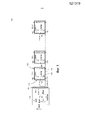
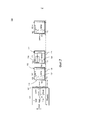
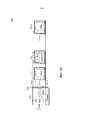
[0063] Фиг. 1 демонстрирует иллюстративный вариант осуществления блока освещения на основе СИД.[0063] FIG. 1 shows an illustrative embodiment of an LED-based lighting unit.
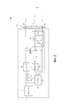
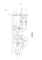
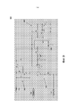
[0064] Фиг. 2 демонстрирует один иллюстративный вариант осуществления возбудителя освещения для блока освещения на основе СИД.[0064] FIG. 2 shows one illustrative embodiment of a lighting driver for an LED-based lighting unit.
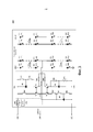
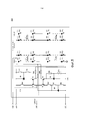
[0065] Фиг. 3 - принципиальная схема одного иллюстративного варианта осуществления модуля СИД.[0065] FIG. 3 is a schematic diagram of one illustrative embodiment of an LED module.
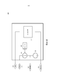
[0066] Фиг. 4 - блок-схема другого иллюстративного варианта осуществления модуля СИД.[0066] FIG. 4 is a block diagram of another illustrative embodiment of an LED module.
[0067] Фиг. 5 - принципиальная схема еще одного варианта осуществления модуля СИД.[0067] FIG. 5 is a schematic diagram of another embodiment of an LED module.
[0068] Фиг. 6 демонстрирует другой иллюстративный вариант осуществления возбудителя освещения для блока освещения на основе СИД.[0068] FIG. 6 shows another illustrative embodiment of a lighting driver for an LED-based lighting unit.
[0069] Фиг. 7 демонстрирует другой иллюстративный вариант осуществления блока освещения на основе СИД.[0069] FIG. 7 shows another illustrative embodiment of an LED-based lighting unit.
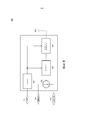
[0070] Фиг. 8 - функциональная блок-схема одного варианта осуществления модуля датчика.[0070] FIG. 8 is a functional block diagram of one embodiment of a sensor module.
[0071] Фиг. 9 - принципиальная схема одного варианта осуществления модуля датчика.[0071] FIG. 9 is a schematic diagram of one embodiment of a sensor module.
[0072] Фиг. 10 демонстрирует еще один иллюстративный вариант осуществления блока освещения на основе СИД.[0072] FIG. 10 shows another illustrative embodiment of an LED-based lighting unit.
Подробное описаниеDetailed description
[0073] Как рассмотрено выше, нежелательно, чтобы приходилось изготавливать, хранить и обеспечивать разные возбудители освещения для разных блоков освещения на основе СИД в зависимости от количества модулей СИД, которые включены в разные блоки. Также нежелательно эксплуатировать СИД в блоке освещения на основе СИД при слишком высоких температурах, поскольку это может приводить к сокращению срока эксплуатации СИД.[0073] As discussed above, it is undesirable to have to produce, store, and provide different illumination drivers for different LED-based lighting units depending on the number of LED modules that are included in the different units. It is also undesirable to operate the LEDs in the LED-based lighting unit at too high temperatures, as this can lead to a reduction in the life of the LEDs.
[0074] Таким образом, заявители пришли к выводу, что было бы полезно обеспечить возбудитель освещения, который можно установить в различных блоках освещения на основе СИД, которые сильно различаются количеством включенных СИД и модулей СИД и которые можно изготавливать на предприятии без необходимости в особом оборудовании и персонале с особыми знаниями и способностью программировать возбудитель освещения. Заявители пришли к выводу, что было бы полезно обеспечить такой возбудитель освещения, который может снижать ток, подаваемый на СИД, когда температура модуля СИД превышает номинальную или пороговую величину.[0074] Thus, the applicants came to the conclusion that it would be useful to provide a lighting driver that can be installed in various LED-based lighting units, which vary greatly in the number of LEDs and LED modules that are turned on, and which can be manufactured in the enterprise without the need for special equipment and personnel with special knowledge and ability to program the lighting driver. Applicants have concluded that it would be useful to provide a lighting driver that can reduce the current supplied to the LEDs when the temperature of the LED module exceeds a nominal or threshold value.
[0075] Ввиду вышеизложенного, различные варианты осуществления и реализации настоящего изобретения относятся к саморегулирующемуся возбудителю освещения и блоку освещения на основе СИД, который включает в себя саморегулирующийся возбудитель освещения.[0075] In view of the foregoing, various embodiments and implementations of the present invention relate to a self-regulating exciter of illumination and a lighting unit based on LEDs, which includes a self-regulating exciter of illumination.
[0076] Фиг. 1 демонстрирует иллюстративный вариант осуществления светодиодного (СИД) блока 100 освещения, который включает в себя возбудитель 110 освещения, присоединенный к нескольким (N) модулям 120-1~120-N СИД кабелем 130, состоящим из трех жил, как описано более подробно ниже со ссылкой на Фиг. 2. В некоторых вариантах осуществления N может быть равно 1.[0076] FIG. 1 shows an illustrative embodiment of an LED (LED)
[0077] В общем случае, возбудитель 110 освещения может включать в себя любую стандартную схему для подачи управляемого тока I_Drive возбуждения СИД на модули 120-1~120-N СИД совместно со схемой, примеры которой описаны ниже, для автоматической регулировки уровня или величины этого тока I_Drive возбуждения СИД в соответствии с требованиями к току соединенных модулей 120-1~120-N СИД. В конкретном варианте осуществления, как объяснено ниже, возбудитель 110 освещения включает в себя схему, которая может работать совместно с модулями 120-1~120-N СИД для автоматической саморегулировки уровня или величины тока I_Drive возбуждения СИД в сторону увеличения при увеличении количества N модулей СИД, присутствующих в блоке 100 освещения на основе СИД, и в сторону уменьшения при уменьшении количества N модулей СИД, присутствующих в блоке 100 освещения на основе СИД. Таким образом, можно использовать один и тот же возбудитель 110 освещения, например, для первого варианта осуществления блока 100 освещения на основе СИД, имеющего N=8 модулей 120 СИД, и для второго варианта осуществления блока 100 освещения на основе СИД, имеющего N=4 модуля СИД.[0077] In general, the
[0078] Модуль 120 СИД включает в себя одну или более цепочек 122 СИД, первый источник 124 тока, второй источник 126 тока и монтажную плату 128. Во избежание замешательства и для ясности, первый источник 124 тока далее именуется “источником тока идентификации” 124, и второй источник 126 тока далее именуется “источником тока температурной компенсации” 126.[0078] The
[0079] В некоторых вариантах осуществления блоков освещения модуль СИД может не включать в себя источник 126 тока температурной компенсации. В некоторых вариантах осуществления блоков освещения модуль СИД может не включать в себя отдельную монтажную плату. Соответственно, термин “модуль СИД” следует, в широком смысле, рассматривать применительно к блоку, который включает в себя, как минимум, по меньшей мере, один СИД и, по меньшей мере, один источник 124 тока идентификации.[0079] In some embodiments of the lighting units, the LED module may not include a temperature compensation
[0080] Как показано на Фиг. 1, каждый модуль 120-i СИД принимает ток возбуждения СИД на узле или контакте 160 ввода тока возбуждения СИД как часть полного тока I_Drive возбуждения СИД, выводимого возбудителем 110 освещения, и возвращает обратный ток I_Drive_Ret возбуждения СИД через узел или контакт 170 возврата тока возбуждения СИД. Модуль 120 СИД также выводит ток I_Module идентификации модуля СИД через узел или контакт 180 вывода тока идентификации модуля СИД. Как будет более подробно объяснено ниже в отношении рассмотрения Фиг. 3, ток I_Module идентификации модуля СИД равен разности между током I_Ident источника 124 тока идентификации и током I_Temp температурной компенсации источника 126 тока температурной компенсации:[0080] As shown in FIG. 1, each LED module 120-i receives the LED drive current at the LED drive current input node or terminal 160 as part of the total LED drive current I_Drive outputted by the
(1) I_Module = I_Ident - I_Temp.(1) I_Module = I_Ident - I_Temp.
[0081] Как показано на Фиг. 1, каждый из модулей 120-1~120-N СИД выводит соответствующий ток I_Module_1~I_Module_N идентификации модуля СИД. Все узлы 180 вывода тока идентификации модуля СИД множества модулей 120-1~120-N СИД соединены друг с другом для подачи полного тока I_Module_Tot идентификации модуля СИД на возбудитель 110 освещения, где[0081] As shown in FIG. 1, each of the LED modules 120-1 ~ 120-N outputs a corresponding identification current I_Module_1 ~ I_Module_N of the LED module. All
(2) ![]()
![]()
[0082] Полный ток I_Module_Tot идентификации модуля СИД имеет величину полного тока идентификации модуля СИД, которая изменяется в соответствии с количеством (N) множества модулей 120 СИД, которые присутствуют в блоке 100 освещения на основе СИД.[0082] The total LED module identification current I_Module_Tot has a total LED module identification current value that varies in accordance with the number (N) of a plurality of
[0083] В частности, предполагая в порядке примера, что каждый из модулей 120-1~120-N СИД выводит ток I_Module идентификации модуля СИД одинакового уровня или одинаковой величины, получаем, что полный ток идентификации I_Module_Tot равен:[0083] In particular, assuming, by way of example, that each of the LED modules 120-1 ~ 120-N outputs an identification current I_Module of the LED module of the same level or the same magnitude, we obtain that the total identification current I_Module_Tot is:
(3) I_Module_Tot = N * I_Module.(3) I_Module_Tot = N * I_Module.
Этот пример может применяться, например, в вариантах осуществления, где все модули 120-1~120-N СИД включают в себя одинаковое количество цепочек СИД и не включают в себя ни одного источника 126 тока температурной компенсации. Кроме того, уравнение (3) может применяться в случае, когда ни один из источников 126 тока температурной компенсации не включен из-за высокой температуры в соответствующем модуле 120 СИД, как будет более подробно объяснено ниже в отношении рассмотрения Фиг. 3.This example can be applied, for example, in embodiments where all LED modules 120-1 ~ 120-N include the same number of LED strings and do not include any temperature compensation
[0084] Таким образом, полный ток I_Module_Tot идентификации модуля СИД обеспечивает указание количества модулей 120-1~120-N СИД, присоединенных к возбудителю 110 освещения, подлежащих возбуждению возбудителем 110 освещения. В более общем случае, I_Module_Tot обеспечивает для возбудителя 110 освещения указание требований к току возбуждения соединенных модулей 120-1~120-N СИД.[0084] Thus, the total LED module identification current I_Module_Tot provides an indication of the number of LED modules 120-1 ~ 120-N connected to the
[0085] Фиг. 2 демонстрирует один иллюстративный вариант осуществления возбудителя 200 освещения для блока освещения на основе СИД. Возбудитель 200 освещения может быть одним вариантом осуществления возбудителя 110 освещения в блоке 100 освещения. Возможны многие другие конкретные конструкции схемы для других вариантов осуществления возбудителя 200 освещения, которые отличаются от показанных на Фиг. 2, но этот вариант осуществления изложен в порядке примера для иллюстрации саморегулирующегося возбудителя освещения, регулирующего уровень или величину тока возбуждения СИД в соответствии с полным током I_Module_Tot идентификации модуля СИД, подаваемым на него множеством модулей СИД.[0085] FIG. 2 shows one illustrative embodiment of a
[0086] Возбудитель 200 освещения включает в себя выпрямитель 210, устройство 220 переключения, контроллер 230, источник 240 Vcc, силовую цепь 250, резисторную делительную цепь 260 и, в необязательном порядке, датчик 270 напряжения для регистрации напряжения на СИД на выходе возбудителя 200 освещения. Возбудитель 200 освещения также включает в себя узел или контакт 212 вывода тока возбуждения СИД, узел или контакт 214 возврата тока возбуждения СИД и узел или контакт 216 ввода полного тока идентификации. Узел 212 вывода тока возбуждения СИД, узел 214 возврата тока возбуждения СИД и узел 216 ввода полного тока идентификации обеспечивают интерфейс для кабеля 130 для оперативного присоединения возбудителя 200 освещения к одному или более модулям освещения, в частности к модулям СИД. Предпочтительно, кабель 130 состоит только из трех жил, включающих в себя первую жилу, несущую ток I_Drive возбуждения СИД из возбудителя освещения, вторую жилу, несущую обратный ток I_Drive_Ret возбуждения СИД из одного или более модулей освещения, и третью жилу, несущую полный ток I_Module_Tot идентификации модуля СИД из одного или более модулей освещения на возбудитель 200 освещения. Резисторная делительная цепь 260 включает в себя установочный резистор Rset, присоединенный между узлом 216 ввода тока идентификации и узлом 214 возврата тока возбуждения СИД; измерительный резистор Rsense, присоединенный между узлом 214 возврата тока возбуждения СИД и землей; первый резистор R1, присоединенный между узлом 216 ввода тока идентификации и узлом 218 управления, подающим сигнал Uref регулировки тока возбуждения на контроллер 230; и второй резистор, присоединенный между узлом 218 управления и землей. Обратный ток I_Drive_Ret возбуждения СИД принимается возбудителем 200 освещения через узел 214 возврата тока возбуждения СИД и выдается на контроллер 230, который измеряется на измерительном резисторе Rsense для управления величиной тока I_Drive возбуждения СИД.[0086] The
[0087] В ходе эксплуатации устройство 220 переключения совместно с силовой цепью 250 функционирует как управляемый источник тока или источник для тока I_Drive возбуждения СИД. Контроллер 230 подает сигнал управления переключением на устройство 220 переключения через переключающий возбудитель 250. Управляя скважностью переключения и/или частотой переключения устройства 220 переключения, контроллер 230 может управлять величиной или уровнем тока I_Drive возбуждения СИД. Контроллер 230 устанавливает скважность и/или частоту переключения устройства 220 переключения и, таким образом, величину или уровень тока I_Drive возбуждения СИД в соответствии с напряжением Uref, генерируемым резисторной делительной цепью 260, которое, в свою очередь, генерируется из полного тока I_Module_Tot идентификации модуля СИД согласно уравнению (4)[0087] During operation, the switching device 220, in conjunction with the
![]()
![]()
[0088] Предпочтительно, R1=R2, и оба R1 и R2 имеют значение, которое гораздо больше Rset, тогда как значение Rset, в свою очередь, гораздо больше значения Rsense (например, Rset ≈ 1000*Rsense).[0088] Preferably, R1 = R2, and both R1 and R2 have a value that is much larger than Rset, while the Rset value, in turn, is much larger than the Rsense value (for example, Rset ≈ 1000 * Rsense).
[0089] Контроллер 230 использует напряжение Uref в качестве сигнала регулировки тока возбуждения СИД для регулировки величины или уровня тока I_Drive возбуждения СИД, которые выражаются как[0089] The
(5) ![]()
![]()
[0090] Поэтому, как можно видеть из уравнения (5), ток I_Drive возбуждения СИД является функцией полного тока I_Module_Tot идентификации модуля СИД, выдаваемого модулями СИД. Совместно с уравнением (3), в случае, когда все из каждого из модулей СИД выводят ток I_Module идентификации модуля СИД с одним и тем же уровнем или величиной, ток I_Drive возбуждения СИД приобретает вид[0090] Therefore, as can be seen from Equation (5), the LED driving current I_Drive is a function of the total identification current I_Module_Tot of the LED module generated by the LED modules. Together with equation (3), in the case when all of each of the LED modules output the identification module current I_Module of the LED module with the same level or value, the LED driving current I_Drive takes the form
(6) ![]()
![]()
[0091] Из уравнений (5) и (6) можно видеть, что возбудитель 200 освещения автоматически саморегулирует ток I_Drive возбуждения СИД, который он вырабатывает, в соответствии с количеством N модулей СИД, которые присутствуют в блоке освещения и возбуждаются возбудителем 200 освещения.[0091] From equations (5) and (6), it can be seen that the
[0092] Кроме того, в случае, когда каждый модуль СИД включает в себя источник тока температурной компенсации, как показано на Фиг. 1 и описано более подробно ниже со ссылкой на Фиг. 3, полный ток I_Module_Tot идентификации модуля СИД будет снижаться, когда регистрируемая температура любого одного или более модулей СИД превышает номинальную или пороговую температуру. Таким образом, согласно уравнению (5), ток I_Drive возбуждения СИД также будет снижаться, уменьшая ток, подаваемый на СИД модулей СИД, таким образом понижая их рабочие температуры и продлевая их предполагаемые сроки эксплуатации.[0092] Furthermore, in the case where each LED module includes a temperature compensation current source, as shown in FIG. 1 and described in more detail below with reference to FIG. 3, the total current of the identification of the LED module I_Module_Tot will decrease when the recorded temperature of any one or more LED modules exceeds the nominal or threshold temperature. Thus, according to equation (5), the LED driving current I_Drive will also decrease, decreasing the current supplied to the LEDs of the LED modules, thereby lowering their operating temperatures and extending their expected life.
[0093] На Фиг. 3 показана принципиальная схема одного варианта осуществления модуля 300 СИД. Модуль 300 СИД включает в себя множество (K) цепочек 322-1~322-K СИД, причем каждая из цепочек 322-1~322-K СИД включает в себя множество СИД 323, последовательно соединенных друг с другом, и в ряде случаев может включать в себя первую группу из M (например, M=5) СИД 323, последовательно соединенных со второй группой из P (например, P=6) СИД 323. Модуль 300 СИД также включает в себя первый источник 324 тока “идентификации” и второй источник 326 тока “температурной компенсации”.[0093] FIG. 3 is a schematic diagram of one embodiment of an
[0094] Источник 324 тока идентификации включает в себя транзисторы T1 и T3, шунтирующий эталонный источник напряжения Q1 и резисторы R3, R4 и Re1 и присоединен между узлом или контактом 360 ввода тока возбуждения СИД и узлом или контактом 380 вывода тока идентификации модуля СИД. Источник 326 тока температурной компенсации включает в себя транзисторы T5 и T7, эталонные источники Q5 и Q7 напряжения, резисторы R5, R7, R8 и Re7 и элемент с отрицательным температурным коэффициентом NTC. Транзисторные пары T1 и T3 и T5 и T7 могут представлять собой согласованные двойные транзисторы, двойные транзисторы или два одиночных транзистора, в зависимости от желаемого допуска для соответствующего источника тока. Резисторы Rc1, Rc5 и R соединяют друг с другом источник 324 тока идентификации, источник 326 тока температурной компенсации и цепочку 322-1 СИД.[0094] The identification
[0095] В ходе эксплуатации модуль 300 СИД принимает часть тока I_Drive возбуждения СИД через узел 360 ввода тока возбуждения СИД и возвращает часть обратного тока I_Drive_Ret возбуждения СИД через узел или контакт 370 возврата тока возбуждения СИД. Узел 360 ввода тока возбуждения СИД присоединен к СИД 323 цепочек 322-1~322-K СИД, и модуль 300 СИД подает часть тока I_Drive возбуждения СИД на СИД 323 цепочек 322-1~322-K СИД.[0095] During operation, the
[0096] Источник 324 тока идентификации вырабатывает ток I_Ident. В условиях эксплуатации, когда регистрируемая температура модуля 300 СИД меньше номинального или порогового значения, источник 326 тока температурной компенсации отключается. В этом случае модуль 300 СИД выводит ток I_Ident из узла 380 вывода тока идентификации модуля СИД в качестве тока I_Module идентификации модуля СИД.[0096] The identification
[0097] Когда регистрируемая температура модуля 300 СИД возрастает сверх номинальной или пороговой температуры, источник 326 тока температурной компенсации выполнен с возможностью снижения тока идентификации I_Module, поступающего от модуля 300 СИД. Q7 и Q5 образуют два источника напряжения, один из которых зависит от температуры благодаря элементу с отрицательным температурным коэффициентом NTC. Например, в одном варианте осуществления NTC может иметь импеданс 15 кОм при 35°C и сниженный импеданс 2,5 кОм при +70°C. Поскольку импеданс NTC уменьшается с температурой, в определенной точке запуска (соответствующей, например, заранее определенной пороговой температуре) напряжение на эмиттере T5 будет равно и затем превысит напряжение эталонного источника Q7 напряжения. Когда напряжение на эмиттере T5 становится больше напряжения эталонного источника Q7 напряжения, транзистор T7 переходит в проводящее состояние, вырабатывая ток I_Temp температурной компенсации, величина которого возрастает с увеличением температуры модуля 300 СИД. Ток I_Temp температурной компенсации вычитается из тока коллектора T3, что приводит к снижению тока I_Module идентификации модуля СИД, выводимого из узла 380 вывода тока идентификации модуля СИД. Как объяснено выше со ссылкой на Фиг. 1 и 2 и как следует из вышеприведенных уравнений (2) и (5), когда I_Module для одного или более модулей 300 СИД снижается, ток I_Drive возбуждения СИД, подаваемый возбудителем освещения, также уменьшается, снижая ток, проходящий через СИД 323, и, таким образом, снижая температуру модуля 300 СИД.[0097] When the recorded temperature of the
[0098] Как упомянуто выше, в некоторых вариантах осуществления модуль 300 СИД может не содержать источник 326 тока температурной компенсации, при этом недостаток возбудителя освещения состоит в том, что он больше не способен автоматически регулировать (уменьшать) ток возбуждения СИД при увеличении температуры СИД. В этом случае ток I_Module идентификации модуля СИД равен I_Ident, вырабатываемому источником 324 тока идентификации.[0098] As mentioned above, in some embodiments, the
[0099] В некоторых вариантах осуществления, когда температура конкретного модуля 300 СИД продолжает расти, ток I_Temp температурной компенсации для этого конкретного модуля 300 СИД может увеличиваться, пока не превысит ток I_Ident, отбирая ток из источников 324 тока идентификации других модулей 300 СИД, к которым он присоединен, и в этом случае конкретный модуль СИД снижает полный ток I_Module_Tot идентификации модуля СИД, который поступает в качестве обратной связи на возбудитель СИД.[0099] In some embodiments, when the temperature of a
[0100] Модуль 300 СИД, в необязательном порядке, включает в себя, по меньшей мере, один датчик 330 и переключатель 340. Датчик(и) 330 может(ут) включать в себя датчик окружающего света и/или детектор присутствия, позволяющий управлять освещением, создаваемым модулем 300 СИД, в соответствии с условиями окружающей среды. Например, когда датчик 330 является детектором окружающего света, который обнаруживает, что уровень окружающего света в окружении модуля 300 СИД выше определенного порога, и/или когда датчик 330 является детектором присутствия, который не обнаруживает присутствия каких-либо людей в окружении модуля 300 СИД, может быть желательно снижать или отключать освещение, обеспечиваемое модулем 300 СИД, для снижения энергопотребления. В этом случае можно управлять одним или более переключателями (например, переключателем 340) для запрещения приема тока I_Drive возбуждения СИД и/или запрещения вывода тока I_Module идентификации модуля СИД, когда, например, обнаруживается, что уровень окружающего света в окружении модуля 300 СИД выше определенного порога и/или что в окружении модуля 300 СИД нет никаких людей.[0100] The
[0101] Таким образом, как объяснено выше, в блоке 100 освещения, имеющем вышеописанные модули СИД со встроенным источником тока идентификации, саморегулирующийся возбудитель освещения может автоматически согласовывать свой ток возбуждения СИД с требованиями соединенных модулей СИД. В частности, возбудитель СИД освещения может подавать ток возбуждения СИД, причем величина тока возбуждения СИД изменяется в соответствии с количеством множества модулей СИД, которые присутствуют в системе.[0101] Thus, as explained above, in the
[0102] В вариантах осуществления, описанных выше со ссылкой на Фиг. 1-3, шина или кабель 130, имеющий только три жилы, применяется для соединения возбудителя освещения и одного или более модулей СИД. Соответственно, интерфейс возбудителя освещения с модулем(ями) СИД включает в себя только три узла или контакта (например, узел 212 вывода тока возбуждения СИД, узел 214 возврата тока возбуждения СИД и узел 216 ввода полного тока идентификации). Аналогично, интерфейс каждого модуля СИД с возбудителем освещения также включает в себя только три узла или контакта (например, узел 360 ввода тока возбуждения СИД, узел 370 возврата тока возбуждения СИД и узел 380 вывода тока идентификации модуля СИД). В этих вариантах осуществления на источники 324 тока идентификации, которые включены в модули 300 СИД, подается ток I_Drive возбуждения СИД через узел 360 ввода тока возбуждения СИД.[0102] In the embodiments described above with reference to FIG. 1-3, a bus or
[0103] Трехжильный интерфейс представляет неоспоримое преимущество над другими решениями, которые применяют дополнительные жилы, но в некоторых вариантах осуществления возможен случай, когда дополнительный отбор тока из источников тока идентификации может снижать точность глубокого гашения цепочек СИД.[0103] The three-wire interface is an indisputable advantage over other solutions that use additional conductors, but in some embodiments, it is possible that additional current extraction from identification current sources can reduce the accuracy of deep quenching of LED circuits.
[0104] На Фиг. 4 показана блок-схема другого иллюстративного варианта осуществления модуля 400 СИД.[0104] In FIG. 4 is a block diagram of another illustrative embodiment of an
[0105] Модуль 400 СИД имеет четырехузловой или четырехконтактный интерфейс с возбудителем освещения и требует четырехжильной(ого) шины или кабеля по сравнению с трехжильной(ым) шиной или кабелем 130, показанной(ым) на Фиг. 1 и 2. В частности, модуль СИД включает в себя узел или контакт 410 ввода питания источника тока. Преимущество дополнительной жилы интерфейса и дополнительного входного контакта для модуля 400 СИД состоит в том, что источник 324 тока идентификации и источник 326 тока температурной компенсации получают ввод от возбудителя освещения по другому, отдельному соединению, чем узел 360 ввода тока возбуждения СИД, который принимает ток I_Drive возбуждения СИД для нагрузки 422 СИД. В результате, ток, отбираемый источником 324 тока идентификации, не снижает точность управления сниженным током I_Drive возбуждения СИД для нагрузки 422 СИД при работе в режиме глубокого гашения.[0105] The
[0106] Модуль 400 СИД также включает в себя модулятор 420 для модуляции тока I_Module идентификации модуля СИД и, таким образом, полного тока I_Module_Tot идентификации модуля СИД, возвращаемого на возбудитель освещения цифровым сигналом (например, со скоростью передачи данных в несколько килобит). Эти данные можно обнаруживать на возбудителе освещения для обеспечения возможности передачи данных от модуля 400 СИД на возбудитель освещения. Такие данные могут включать в себя, например, рабочие данные и/или данные окружения, относящиеся к модулю СИД, например, температуру окружающей среды, рабочую температуру модуля 400 СИД, цветовую точку света, выводимого модулем 400 СИД или блоком 100 освещения на основе СИД, или любые другие данные, представляющие интерес. Среднее (DC) значение полного тока I_Module_Tot идентификации модуля СИД, возвращаемого на возбудитель освещения, может не зависеть от модулированных данных, что позволяет возбудителю освещения по-прежнему правильно регулировать ток I_Drive возбуждения СИД согласно количеству модулей СИД, которые он возбуждает. В различных вариантах осуществления могут применяться различные формы модуляции, в том числе частотная модуляция, амплитудная модуляция, фазовая модуляция. В некоторых вариантах осуществления может применяться манчестерское кодирование, позволяющее гарантировать, что среднее значение полного тока I_Module_Tot идентификации модуля СИД не зависит от конкретных передаваемых данных.[0106] The
[0107] Конечно, следует понимать, что хотя, для наглядности, модуль 400 СИД показан включающим в себя оба признака отдельного узла или контакта для ввода в источник 324 тока идентификации и источник 326 тока температурной компенсации (т.е. использует четырехжильную(ый) шину или кабель) и модулятор 420, в других вариантах осуществления модуль СИД может включать в себя только тот или иной из этих признаков (или, конечно, ни одного из признаков, как показано выше в модуле 300 СИД).[0107] Of course, it should be understood that although, for clarity, the
[0108] На Фиг. 5 показана принципиальная схема еще одного варианта осуществления модуля 500 СИД. Модуль 500 СИД аналогичен модулю 500 СИД, показанному на Фиг. 5 и описанному выше, поэтому будут подробно описаны только различия между модулем 500 СИД и модулем 300 СИД. В частности, модуль 500 СИД включает в себя отдельный узел или контакт 410 ввода питания источника тока для приема от возбудителя освещения напряжения для источника 324 тока идентификации и источника 326 тока температурной компенсации, как описано выше со ссылкой на Фиг. 4.[0108] In FIG. 5 is a schematic diagram of another embodiment of an
[0109] Фиг. 6 демонстрирует другой иллюстративный вариант осуществления возбудителя 600 освещения для блока освещения на основе СИД, который может применяться с модулем 400 СИД или модулем 500 СИД. Возбудитель 600 освещения аналогичен возбудителю 200 освещения, показанному на Фиг. 2 и описанному выше, поэтому будут подробно описаны только различия между возбудителем 600 освещения и возбудителем 200 освещения. В частности, возбудитель 600 освещения включает в себя источник 610 напряжения и узел или контакт 618 напряжения питания источника тока идентификации, который подает напряжение V_Source питания источника тока идентификации на один или более источников 324 тока идентификации на одном или более модулях СИД, например модуле 400 СИД или модуле 500 СИД, отдельно от тока I_Drive возбуждения СИД для нагрузки СИД, содержащей цепочки СИД 322-I. Соответственно, возбудитель 600 освещения сопрягается с одним или более модулями СИД, например, модулем 400 СИД или модулем 500 СИД через четырехжильный кабель или шину 630.[0109] FIG. 6 shows another illustrative embodiment of a
[0110] Фиг. 7 демонстрирует другой иллюстративный вариант осуществления блока 700 освещения на основе СИД.[0110] FIG. 7 shows another illustrative embodiment of an LED-based
[0111] Блок 700 освещения на основе СИД аналогичен блоку 100 освещения на основе СИД, показанному на Фиг. 1 и описанному выше, поэтому будут подробно описаны только различия между блоком 100 освещения на основе СИД и блоком 700 освещения на основе СИД. В частности, блок 700 освещения на основе СИД включает в себя модуль 720 датчика, присоединенный к возбудителю 110 освещения и модулям 120-1~120-N СИД трехжильным кабелем 130.[0111] The LED-based
[0112] Модуль 720 датчика включает в себя один или более датчиков 722, контроллер 730 и управляемый приемник 726 тока. Модуль 720 датчика также имеет узел или контакт 760 ввода питания, который присоединен для приема части полного тока I_Drive возбуждения СИД, выводимого возбудителем 110 освещения. Модуль 720 датчика дополнительно присоединен к линии обратного тока I_Drive_Ret возбуждения через узел 170 возврата.[0112] The
[0113] В ходе эксплуатации, под управлением контроллера 730, например в соответствии с одним или более выходными сигналами датчика(ов) 722, управляемый приемник 726 тока модуля 720 датчика отводит управляемую величину тока I_Sensor через узел или контакт 780 приема тока идентификации модуля освещения как часть полного тока I_Module_Tot идентификации модуля СИД для блока 700 освещения на основе СИД.[0113] During operation, under the control of the
[0114] Например, датчик 722 может регистрировать величину окружающего света в окрестности модуля 720 датчика и, в соответствии с ней, может генерировать выходной сигнал датчика для контроллера 730, в соответствии с которым контроллер 730 может побуждать управляемый приемник 726 тока отводить ток I_Sensor через узел 780 приема тока идентификации модуля освещения, таким образом регулируя полный ток I_Module_Tot идентификации модуля СИД для блока 700 освещения на основе СИД. В соответствии с отрегулированным полным током I_Module_Tot идентификации модуля СИД возбудитель 110 освещения может, соответственно, регулировать полный ток I_Drive возбуждения СИД, выводимый возбудителем 110 освещения, таким образом управляя уровнем светового выхода цепочек 122 СИД в модулях 120-1~120-N СИД. Таким образом, может осуществляться, например, управляемое гашение света, выводимого цепочками СИД 122 модулей 120-1~120-N СИД.[0114] For example, the
[0115] В порядке другого примера, датчик 722 может определять, присутствует ли человек в окрестности модуля 720 датчика и, в соответствии с этим, может генерировать выходной сигнал датчика для контроллера 730. В соответствии с выходным сигналом датчика, указывающим, присутствует ли человек в окрестности модуля 720 датчика, контроллер 730 может побуждать управляемый приемник 726 тока отводить ток I_Sensor через узел 780 приема тока идентификации модуля освещения, таким образом регулируя полный ток I_Module_Tot идентификации модуля СИД для блока 700 освещения на основе СИД. В соответствии с отрегулированным полным током I_Module_Tot идентификации модуля СИД возбудитель 110 освещения может, соответственно, регулировать полный ток I_Drive возбуждения СИД, выводимый возбудителем 110 освещения, таким образом управляя уровнем светового выхода цепочек 122 СИД в модулях 120-1~120-N СИД. Таким образом, например, возбудитель 110 освещения может регулировать ток I_Drive возбуждения СИД таким образом, чтобы цепочки СИД 122 модулей 120-1~120-N СИД имели первый уровень света (например, номинальный уровень света), когда детектор присутствия обнаруживает присутствие человека в окрестности модуля датчика, и имели второй уровень света (например, пониженный уровень света или нулевой уровень света), который меньше первого уровня света, когда детектор присутствия не обнаруживает присутствия человека в окрестности модуля датчика.[0115] In another example, the
[0116] Модуль 720 датчика позволяет обеспечивать управление освещением, создаваемым блоком 700 освещения на основе СИД, например, для реализации интеллектуального гашения в соответствии с условиями окружающего света и/или обнаружением присутствия; для реализации беспроводного пульта дистанционного управления блока 700 освещения на основе СИД; и т.д. Соответственно, модуль 720 датчика также можно рассматривать как модуль управления или модуль гашения.[0116] The
[0117] На Фиг. 8 показана функциональная блок-схема одного варианта осуществления модуля 800 датчика, который можно применять в качестве модуля 720 датчика в блоке 700 освещения на основе СИД. Модуль 800 датчика включает в себя один или более датчиков или детекторов 822, источник 824, управляемый приемник 826 тока и контроллер 830.[0117] In FIG. 8 is a functional block diagram of one embodiment of a
[0118] Датчик(и)/детектор(ы) 822 может/гут включать в себя детектор присутствия, который обнаруживает, присутствует ли человек в комнате, где располагается модуль 800 датчика или в окрестности модуля 800 датчика. Датчик(и)/детектор(ы) 822 может включать в себя детектор окружающего света для обнаружения уровня окружающего света в комнате, где располагается модуль 800 датчика или в окрестности модуля 800 датчика. Можно применять другие типы датчиков или детекторов. Модуль 800 датчика может, в необязательном порядке, включать в себя антенну 823, и в этом случае датчик/детектор 822 может содержать беспроводной приемник, выполненный с возможностью приема беспроводного сигнала, например сигнал пульта дистанционного управления, включающего в себя данные, указывающие желаемый уровень светового выхода, выводимого блоком освещения на основе СИД, например блоком 700 освещения на основе СИД, который включает в себя модуль 800 датчика (например, для гашения света до желаемого уровня). Датчик(и)/детектор(ы) 822 выводит на контроллер 830 один или более выходных сигналов датчиков, указывающих, например: регистрируемый уровень окружающего света; зарегистрировано ли присутствие человека в окрестности модуля датчика; любые принятые данные, указывающие желаемый уровень светового выхода; и т.д.[0118] Sensor (s) / detector (s) 822 may include a presence detector that detects whether a person is present in the room where the
[0119] В соответствии с одним или более выходными сигналами датчиков контроллер 830 генерирует сигнал управления для управления величиной тока, отводимого управляемым приемником 826 тока, таким образом регулируя полный ток I_Module_Tot идентификации модуля СИД, поступающий на возбудитель освещения. В соответствии со сниженным полным током I_Module_Tot идентификации модуля СИД возбудитель 110 освещения, соответственно, регулирует полный ток I_Drive возбуждения СИД, который он подает на модуль(и) СИД и их световые цепочки, таким образом регулируя свет, выводимый блоком освещения на основе СИД. Таким образом, для гашения света, выводимого блоком освещения на основе СИД, до желаемого уровня можно обеспечить систему с отрицательной обратной связью.[0119] In accordance with one or more sensor outputs, the
[0120] Источник 824 принимает ток через узел 760 ввода питания, который принимает часть полного тока I_Drive возбуждения СИД, выводимого возбудителем освещения, и подает ток для эксплуатации контроллера 830 и датчика(ов)/детектора(ов) 822. Однако в другом варианте осуществления источник 824 может принимать напряжение для контроллера 830 и датчика(ов)/детектора(ов) 822 через узел 760 ввода питания как часть напряжения V_Source, выводимого из отдельного узла или контакта источника напряжения возбудителя освещения, как показано выше со ссылкой на Фиг. 6.[0120] A
[0121] В некоторых вариантах осуществления модуль 800 датчика также может включать в себя возможность модуляции полного тока I_Module_Tot идентификации модуля СИД, возвращаемого на возбудитель освещения, цифровым сигналом (например, со скоростью передачи данных в несколько килобит), аналогично признаку, описанному выше со ссылкой на Фиг. 4.[0121] In some embodiments, the
[0122] На Фиг. 9 показана принципиальная схема одного варианта осуществления модуля 900 датчика, который можно применять в качестве модуля 720 датчика в блоке 700 освещения на основе СИД. Модуль 900 датчика включает в себя один или более датчиков или детекторов 922, источник 924, управляемый приемник тока 926 и контроллер 930.[0122] In FIG. 9 is a schematic diagram of one embodiment of a
[0123] Источник 924, который включает в себя D1 и Q2, обеспечивает источник низкого напряжения для других частей модуля 900 датчика. Если на источник 924 поступает полный ток I_Drive возбуждения СИД, выводимый возбудителем освещения, то нужно учитывать, что ток, отбираемый источником 924 из узла 760 ввода питания, гораздо ниже тока цепочек СИД модулей СИД в блоке освещения. В другом варианте осуществления, если ток, отбираемый источником 924 из узла 760 ввода питания, слишком велик по сравнению с основным током СИД, то модуль 900 датчика может дополнительно включать в себя малый источник тока, который добавляет согласующуюся величину тока к I_Module_Tot, чтобы гарантировать, что возбудитель освещения доставляет чуть больший ток для питания модуля 900 датчика.[0123] A
[0124] В модуле 900 датчика: D2 - это фотодиод, измеряющий окружающий свет, U3 - это усилитель фотодиода, подающий выходной сигнал датчика на контроллер 930. Контроллер 930 может сравнивать уровень окружающего света с заранее определенным значением и может гасить нагрузку СИД, если окружающего света достаточно.[0124] In the sensor module 900: D2 is a photodiode measuring ambient light, U3 is a photodiode amplifier supplying a sensor output to a
[0125] Управляемый источник тока 926 включает в себя транзистор Q1, отводящий ток из линии I_Module_Tot и, таким образом, гасящий СИД.[0125] The controllable
[0126] Хотя различные признаки разных вариантов осуществления проиллюстрированы и описаны выше отдельно со ссылкой на Фиг. 1-9 для обеспечения наглядности в иллюстрации и объяснении, следует понимать, что различные комбинации этих признаков могут применяться в альтернативных вариантах осуществления. Например, некоторые варианты осуществления блока освещения могут использовать модуль датчика совместно с модулями СИД и возбудителем СИД, которые осуществляют связь через четырехжильный интерфейс, который имеет отдельное питание для источников тока, чем питание для цепочек СИД. Фиг. 10 демонстрирует пример такого варианта осуществления блока 1000 освещения на основе СИД, где используется четырехжильный кабель 1030 между возбудителем 1010 освещения и модулями 1020-1~1020-N СИД и датчиком 1040.[0126] Although various features of various embodiments are illustrated and described separately above with reference to FIG. 1-9, for clarity in illustration and explanation, it should be understood that various combinations of these features may be used in alternative embodiments. For example, some embodiments of a lighting unit may use a sensor module in conjunction with LED modules and an LED driver that communicate through a four-wire interface that has separate power for current sources than power for LED circuits. FIG. 10 illustrates an example of such an embodiment of an LED-based
[0127] В другой иллюстративной вариации некоторые варианты осуществления блока освещения могут включать в себя один или более модулей СИД, которые используют узел или контакт I_Drive для питания как источников тока, так и цепочек СИД совместно с одним или более другими модулями СИД, которые применяют специальный узел или контакт ввода для источников тока, отдельный от узла или контакта I_Drive, который питает цепочки СИД. Специалистам в данной области техники очевидно, что возможно большое количество комбинаций этих признаков, и авторы изобретения могут предусмотреть их.[0127] In another illustrative variation, some embodiments of a lighting unit may include one or more LED modules that use an I_Drive assembly or contact to power both current sources and LED circuits in conjunction with one or more other LED modules that use a special node or input contact for current sources, separate from the node or contact I_Drive, which powers the LED circuits. Those skilled in the art will appreciate that a large number of combinations of these features are possible, and the inventors may contemplate them.
[0128] Следует также понимать, что хотя для обеспечения конкретной иллюстрации иллюстративные варианты осуществления были описаны выше в контексте модулей СИД, которые включают в себя источники света на основе СИД, вышеописанные принципы не подлежат ограничению и могут применяться к возбудителям освещения, подающим мощность на модули освещения, которые включают в себя другие типы источников света и которые подают ток идентификации обратно на модуль освещения для облегчения регулировки возбудителем освещения уровня мощности, который он подает в соответствии, например, с количеством модулей освещения, к которым он присоединен.[0128] It should also be understood that although illustrative embodiments have been described above in the context of LED modules, which include LED-based light sources, to provide a specific illustration, the principles described above are not limited and can be applied to light drivers that supply power to the modules lighting, which include other types of light sources and which feed the identification current back to the lighting module to facilitate the adjustment by the pathogen of illumination of the power level that it odaet in accordance, e.g., with the number of lighting modules to which it is attached.
[0129] Хотя здесь описано и проиллюстрировано несколько вариантов осуществления изобретения, специалисты в данной области техники могут предложить различные другие средства и/или структуры для осуществления функции и/или получения результатов и/или одного или более из описанных здесь преимуществ, и каждая из таких вариаций и/или модификаций рассматривается в объеме описанных здесь вариантов осуществления изобретения. В более общем случае, специалистам в данной области техники нетрудно понять, что все описанные здесь параметры, размеры, материалы и конфигурации рассматриваются как иллюстративные и что фактические параметры, размеры, материалы и/или конфигурации будут зависеть от конкретного применения или вариантов применения, для которых используются принципы изобретения. Специалисты в данной области техники смогут понять или определить с использованием не более чем рутинного экспериментирования многие эквиваленты конкретных описанных здесь вариантов осуществления изобретения. Таким образом, следует понимать, что вышеописанные варианты осуществления представлены исключительно в порядке примера и что в объеме нижеследующей формулы изобретения и ее эквивалентов варианты осуществления изобретения можно осуществлять на практике иначе, чем конкретно описано и заявлено. Варианты осуществления изобретения настоящего раскрытия относятся к каждому отдельному описанному здесь признаку, системе, изделию, материалу, комплекту и/или способу. Кроме того, любая комбинация двух или более таких признаков, систем, изделий, материалов, комплектов и/или способов, если такие признаки, системы, изделия, материалы, комплекты и/или способы не являются взаимно-несогласованными, включена в объем настоящего раскрытия.[0129] Although several embodiments of the invention have been described and illustrated, those skilled in the art can propose various other means and / or structures for performing a function and / or obtaining results and / or one or more of the advantages described herein, and each of these variations and / or modifications are contemplated within the scope of the embodiments described herein. More generally, it will be readily apparent to those skilled in the art that all of the parameters, sizes, materials and configurations described herein are considered illustrative and that the actual parameters, dimensions, materials and / or configurations will depend on the particular application or applications for which The principles of the invention are used. Those of ordinary skill in the art will be able to understand or determine, using nothing more than routine experimentation, many equivalents to the specific embodiments of the invention described herein. Thus, it should be understood that the above embodiments are presented solely by way of example and that, in the scope of the following claims and their equivalents, embodiments of the invention can be practiced otherwise than specifically described and claimed. Embodiments of the invention of the present disclosure relate to each individual feature, system, article, material, kit and / or method described herein. In addition, any combination of two or more of such features, systems, products, materials, kits and / or methods, if such features, systems, products, materials, kits and / or methods are not mutually inconsistent, is included in the scope of this disclosure.
[0130] Все определения, заданные и используемые здесь, следует понимать для контроля над словарными определениями, определениями в документах, включенных посредством ссылки, и/или обычными значениями заданных терминов.[0130] All definitions defined and used herein should be understood to control vocabulary definitions, definitions in documents incorporated by reference, and / or the usual meanings of defined terms.
[0131] Единственное число, используемое здесь в описании изобретения и в формуле изобретения, если прямо не указано обратное, следует понимать в смысле “по меньшей мере, один”.[0131] The singular used here in the description of the invention and in the claims, unless expressly stated otherwise, should be understood in the sense of “at least one”.
[0132] Используемое здесь в описании изобретения и в формуле изобретения выражение “по меньшей мере, один”, со ссылкой на список из одного или более элементов, следует понимать в смысле, по меньшей мере, одного элемента, выбранного из любого одного или более из элементов в списке элементов, но не обязательно включающих в себя, по меньшей мере, один из всех элементов, конкретно перечисленных в списке элементов и не исключающих никаких комбинаций элементов в списке элементов. Это определение также допускает, что элементы могут, в необязательном порядке, представлять другие, помимо элементов, конкретно идентифицированных в списке элементов, к которому относится выражение “по меньшей мере, один”, связанные или не связанные с конкретно идентифицированными элементами.[0132] As used herein in the description of the invention and in the claims, the expression “at least one”, with reference to a list of one or more elements, should be understood in the sense of at least one element selected from any one or more of elements in the list of elements, but not necessarily including at least one of all elements specifically listed in the list of elements and not excluding any combination of elements in the list of elements. This definition also assumes that the elements may optionally represent others other than elements specifically identified in the list of elements to which the expression “at least one” refers, whether or not associated with specifically identified elements.
[0133] Следует также понимать, что, если прямо не указано обратное, в любых заявленных здесь способах, которые включают в себя более чем один этап или действие, порядок этапов или действий способа не обязан ограничиваться порядком, в котором перечислены этапы или действия способа.[0133] It should also be understood that, unless expressly stated otherwise, in any of the methods claimed herein that include more than one step or action, the order of steps or actions of the method is not required to be limited to the order in which the steps or actions of the method are listed.
[0134] Кроме того, ссылочные позиции, присутствующие в формуле изобретения в скобках, при наличии, обеспечены исключительно для удобства, и их не следует рассматривать в порядке ограничения формулы изобретения.[0134] Furthermore, the reference numerals present in the claims in parentheses, if any, are provided for convenience only and should not be construed as limiting the claims.
Claims (38)
Applications Claiming Priority (3)
| Application Number | Priority Date | Filing Date | Title |
|---|---|---|---|
| US201261659474P | 2012-06-14 | 2012-06-14 | |
| US61/659,474 | 2012-06-14 | ||
| PCT/IB2013/054410 WO2013186655A2 (en) | 2012-06-14 | 2013-05-28 | Self-adjusting lighting driver for driving lighting sources and lighting unit including self-adjusting lighting driver |
Publications (2)
| Publication Number | Publication Date |
|---|---|
| RU2015100930A RU2015100930A (en) | 2016-08-10 |
| RU2632186C2 true RU2632186C2 (en) | 2017-10-04 |
Family
ID=48783306
Family Applications (1)
| Application Number | Title | Priority Date | Filing Date |
|---|---|---|---|
| RU2015100930A RU2632186C2 (en) | 2012-06-14 | 2013-05-28 | Self-regulating lighting exciter for exciting light sources and lighting unit including self-regulating lighting exciter |
Country Status (6)
| Country | Link |
|---|---|
| US (1) | US9215768B2 (en) |
| EP (1) | EP2862418A2 (en) |
| JP (1) | JP6235574B2 (en) |
| CN (1) | CN104584690B (en) |
| RU (1) | RU2632186C2 (en) |
| WO (1) | WO2013186655A2 (en) |
Families Citing this family (10)
| Publication number | Priority date | Publication date | Assignee | Title |
|---|---|---|---|---|
| EP2618635A1 (en) * | 2012-01-19 | 2013-07-24 | Koninklijke Philips Electronics N.V. | Self-adjusting lighting driver for driving lighting sources and lighting unit including self-adjusting lighting driver |
| DE202014000264U1 (en) | 2014-01-10 | 2015-04-13 | Novomatic Ag | lighting device |
| DE102014208190A1 (en) * | 2014-04-30 | 2015-11-05 | Zumtobel Lighting Gmbh | Circuit arrangement and method for operating LEDs |
| WO2016169961A1 (en) | 2015-04-24 | 2016-10-27 | Philips Lighting Holding B.V. | A solid state lighting module, a lighting circuit and lighting control methods. |
| EP3086624A1 (en) * | 2015-04-24 | 2016-10-26 | Philips Lighting Holding B.V. | A solid state lighting module, a lighting circuit and lighting control methods |
| WO2016198348A1 (en) * | 2015-06-12 | 2016-12-15 | Philips Lighting Holding B.V. | Ac-led with hybrid led channels |
| EP3348119B1 (en) | 2015-09-08 | 2021-05-19 | Signify Holding B.V. | Determining property of unchanged load device |
| CN105827111B (en) * | 2016-05-27 | 2018-09-18 | 深圳茂硕电子科技有限公司 | The power circuit and its operating method of Auto-matching load group number in parallel |
| CN107493629A (en) * | 2017-08-25 | 2017-12-19 | 赛尔富电子有限公司 | A kind of the maximum dimmer parameter acquisition system and method for the light fixture group unknown for rated current |
| US10993303B2 (en) * | 2017-10-05 | 2021-04-27 | Osram Gmbh | Power supply circuit, lighting system, and method of operating a power supply circuit |
Citations (6)
| Publication number | Priority date | Publication date | Assignee | Title |
|---|---|---|---|---|
| US6211626B1 (en) * | 1997-08-26 | 2001-04-03 | Color Kinetics, Incorporated | Illumination components |
| DE10051528A1 (en) * | 2000-10-17 | 2002-05-02 | Vossloh Schwabe Elektronik | Illumination device for modular illumination system e.g. for room lighting, has coding device coupled to power supply device for controlling light output of light modules |
| US20090021955A1 (en) * | 2007-07-17 | 2009-01-22 | I/O Controls Corporation | Control network for led-based lighting system in a transit vehicle |
| US20100164403A1 (en) * | 2008-12-31 | 2010-07-01 | O2Micro, Inc. | Circuits and methods for controlling LCD backlights |
| WO2010091619A1 (en) * | 2009-02-10 | 2010-08-19 | Wong Wah Nam | Method for automatically identifying current in led for illumination |
| RU114508U1 (en) * | 2011-09-30 | 2012-03-27 | Владимир Александрович Соловьев | LED DEVICE |
Family Cites Families (13)
| Publication number | Priority date | Publication date | Assignee | Title |
|---|---|---|---|---|
| EP0778509B1 (en) | 1995-12-06 | 2002-05-02 | International Business Machines Corporation | Temperature compensated reference current generator with high TCR resistors |
| US6693332B2 (en) | 2001-12-19 | 2004-02-17 | Intel Corporation | Current reference apparatus |
| JP2004253364A (en) * | 2003-01-27 | 2004-09-09 | Matsushita Electric Ind Co Ltd | Lighting system |
| US7057359B2 (en) | 2003-10-28 | 2006-06-06 | Au Optronics Corporation | Method and apparatus for controlling driving current of illumination source in a display system |
| WO2006111689A1 (en) * | 2005-04-21 | 2006-10-26 | Radiant Research Limited | Illumination control system for light emitters |
| JP4988192B2 (en) * | 2005-12-12 | 2012-08-01 | 株式会社モリテックス | Lighting device and lighting head used in the lighting device |
| TWI341510B (en) * | 2006-01-26 | 2011-05-01 | Au Optronics Corp | Driver and driving method of semiconductor light emitting device array |
| EP1874097B1 (en) | 2006-06-28 | 2010-06-16 | Osram Gesellschaft mit Beschränkter Haftung | LED circuit with current control |
| US7714517B2 (en) * | 2007-04-19 | 2010-05-11 | Au Optronics Corporation | LED driver with current sink control and applications of the same |
| JP4577525B2 (en) * | 2007-05-31 | 2010-11-10 | 東芝ライテック株式会社 | Lighting device |
| US8569956B2 (en) * | 2009-06-04 | 2013-10-29 | Point Somee Limited Liability Company | Apparatus, method and system for providing AC line power to lighting devices |
| JP5498240B2 (en) * | 2010-04-26 | 2014-05-21 | パナソニック株式会社 | Light source module, lighting device, and lighting apparatus using the same |
| CN104206010A (en) * | 2012-01-20 | 2014-12-10 | 欧司朗有限公司 | Optoelectronic component device |
-
2013
- 2013-05-28 CN CN201380043234.8A patent/CN104584690B/en not_active Expired - Fee Related
- 2013-05-28 WO PCT/IB2013/054410 patent/WO2013186655A2/en active Application Filing
- 2013-05-28 US US14/406,840 patent/US9215768B2/en not_active Expired - Fee Related
- 2013-05-28 EP EP13736651.4A patent/EP2862418A2/en not_active Withdrawn
- 2013-05-28 JP JP2015516707A patent/JP6235574B2/en active Active
- 2013-05-28 RU RU2015100930A patent/RU2632186C2/en active
Patent Citations (6)
| Publication number | Priority date | Publication date | Assignee | Title |
|---|---|---|---|---|
| US6211626B1 (en) * | 1997-08-26 | 2001-04-03 | Color Kinetics, Incorporated | Illumination components |
| DE10051528A1 (en) * | 2000-10-17 | 2002-05-02 | Vossloh Schwabe Elektronik | Illumination device for modular illumination system e.g. for room lighting, has coding device coupled to power supply device for controlling light output of light modules |
| US20090021955A1 (en) * | 2007-07-17 | 2009-01-22 | I/O Controls Corporation | Control network for led-based lighting system in a transit vehicle |
| US20100164403A1 (en) * | 2008-12-31 | 2010-07-01 | O2Micro, Inc. | Circuits and methods for controlling LCD backlights |
| WO2010091619A1 (en) * | 2009-02-10 | 2010-08-19 | Wong Wah Nam | Method for automatically identifying current in led for illumination |
| RU114508U1 (en) * | 2011-09-30 | 2012-03-27 | Владимир Александрович Соловьев | LED DEVICE |
Also Published As
| Publication number | Publication date |
|---|---|
| US20150173142A1 (en) | 2015-06-18 |
| US9215768B2 (en) | 2015-12-15 |
| EP2862418A2 (en) | 2015-04-22 |
| WO2013186655A2 (en) | 2013-12-19 |
| CN104584690B (en) | 2016-12-07 |
| JP6235574B2 (en) | 2017-11-22 |
| WO2013186655A3 (en) | 2014-10-23 |
| CN104584690A (en) | 2015-04-29 |
| RU2015100930A (en) | 2016-08-10 |
| JP2015524150A (en) | 2015-08-20 |
Similar Documents
| Publication | Publication Date | Title |
|---|---|---|
| RU2632186C2 (en) | Self-regulating lighting exciter for exciting light sources and lighting unit including self-regulating lighting exciter | |
| RU2622388C2 (en) | Self-adjusting lighting driver for light sources agitation and lighting device including a self-adjusting lighting driver | |
| US9894725B2 (en) | Current feedback for improving performance and consistency of LED fixtures | |
| CN104170527B (en) | There is no the shunting device in the Lighting Control Assembly of the neutral conductor | |
| US9066402B2 (en) | LED-based lighting fixtures and related methods for thermal management | |
| US9337925B2 (en) | Apparatus and methods for optical control of lighting devices | |
| CN109644534B (en) | Control of isolated auxiliary and DALI power supplies for sensor-ready LED drivers | |
| JP2016534514A (en) | Programmable lighting device, method and system for programming lighting device | |
| JP2015515726A (en) | Apparatus and method for external programming of LED driver processor | |
| TW201431426A (en) | Optical power control system, and power control device and pulse generating module | |
| JP6681592B2 (en) | Signal transmitting device, signal receiving device, lighting system and lighting fixture, and lighting system | |
| US9258867B2 (en) | Light emitting apparatus and method of operating thereof | |
| JP6198812B2 (en) | LED lighting system | |
| CN103907399B (en) | For driving the self-regulation illumination driver of light source and including the lighting unit of self-regulation illumination driver |
Legal Events
| Date | Code | Title | Description |
|---|---|---|---|
| HZ9A | Changing address for correspondence with an applicant |