RU2622473C2 - Method and device for electric plant maintenance - Google Patents
Method and device for electric plant maintenance Download PDFInfo
- Publication number
- RU2622473C2 RU2622473C2 RU2013109418A RU2013109418A RU2622473C2 RU 2622473 C2 RU2622473 C2 RU 2622473C2 RU 2013109418 A RU2013109418 A RU 2013109418A RU 2013109418 A RU2013109418 A RU 2013109418A RU 2622473 C2 RU2622473 C2 RU 2622473C2
- Authority
- RU
- Russia
- Prior art keywords
- electrical
- installation
- malfunction
- criticality
- events
- Prior art date
Links
Images


Classifications
-
- B—PERFORMING OPERATIONS; TRANSPORTING
- B23—MACHINE TOOLS; METAL-WORKING NOT OTHERWISE PROVIDED FOR
- B23P—METAL-WORKING NOT OTHERWISE PROVIDED FOR; COMBINED OPERATIONS; UNIVERSAL MACHINE TOOLS
- B23P6/00—Restoring or reconditioning objects
-
- G—PHYSICS
- G01—MEASURING; TESTING
- G01R—MEASURING ELECTRIC VARIABLES; MEASURING MAGNETIC VARIABLES
- G01R31/00—Arrangements for testing electric properties; Arrangements for locating electric faults; Arrangements for electrical testing characterised by what is being tested not provided for elsewhere
- G01R31/08—Locating faults in cables, transmission lines, or networks
-
- G—PHYSICS
- G06—COMPUTING; CALCULATING OR COUNTING
- G06Q—INFORMATION AND COMMUNICATION TECHNOLOGY [ICT] SPECIALLY ADAPTED FOR ADMINISTRATIVE, COMMERCIAL, FINANCIAL, MANAGERIAL OR SUPERVISORY PURPOSES; SYSTEMS OR METHODS SPECIALLY ADAPTED FOR ADMINISTRATIVE, COMMERCIAL, FINANCIAL, MANAGERIAL OR SUPERVISORY PURPOSES, NOT OTHERWISE PROVIDED FOR
- G06Q10/00—Administration; Management
- G06Q10/06—Resources, workflows, human or project management; Enterprise or organisation planning; Enterprise or organisation modelling
-
- G—PHYSICS
- G06—COMPUTING; CALCULATING OR COUNTING
- G06Q—INFORMATION AND COMMUNICATION TECHNOLOGY [ICT] SPECIALLY ADAPTED FOR ADMINISTRATIVE, COMMERCIAL, FINANCIAL, MANAGERIAL OR SUPERVISORY PURPOSES; SYSTEMS OR METHODS SPECIALLY ADAPTED FOR ADMINISTRATIVE, COMMERCIAL, FINANCIAL, MANAGERIAL OR SUPERVISORY PURPOSES, NOT OTHERWISE PROVIDED FOR
- G06Q10/00—Administration; Management
- G06Q10/20—Administration of product repair or maintenance
-
- G—PHYSICS
- G01—MEASURING; TESTING
- G01R—MEASURING ELECTRIC VARIABLES; MEASURING MAGNETIC VARIABLES
- G01R31/00—Arrangements for testing electric properties; Arrangements for locating electric faults; Arrangements for electrical testing characterised by what is being tested not provided for elsewhere
-
- G—PHYSICS
- G05—CONTROLLING; REGULATING
- G05B—CONTROL OR REGULATING SYSTEMS IN GENERAL; FUNCTIONAL ELEMENTS OF SUCH SYSTEMS; MONITORING OR TESTING ARRANGEMENTS FOR SUCH SYSTEMS OR ELEMENTS
- G05B23/00—Testing or monitoring of control systems or parts thereof
- G05B23/02—Electric testing or monitoring
- G05B23/0205—Electric testing or monitoring by means of a monitoring system capable of detecting and responding to faults
- G05B23/0259—Electric testing or monitoring by means of a monitoring system capable of detecting and responding to faults characterized by the response to fault detection
- G05B23/0283—Predictive maintenance, e.g. involving the monitoring of a system and, based on the monitoring results, taking decisions on the maintenance schedule of the monitored system; Estimating remaining useful life [RUL]
-
- G—PHYSICS
- G05—CONTROLLING; REGULATING
- G05D—SYSTEMS FOR CONTROLLING OR REGULATING NON-ELECTRIC VARIABLES
- G05D23/00—Control of temperature
- G05D23/01—Control of temperature without auxiliary power
- G05D23/02—Control of temperature without auxiliary power with sensing element expanding and contracting in response to changes of temperature
-
- H—ELECTRICITY
- H02—GENERATION; CONVERSION OR DISTRIBUTION OF ELECTRIC POWER
- H02H—EMERGENCY PROTECTIVE CIRCUIT ARRANGEMENTS
- H02H3/00—Emergency protective circuit arrangements for automatic disconnection directly responsive to an undesired change from normal electric working condition with or without subsequent reconnection ; integrated protection
-
- Y—GENERAL TAGGING OF NEW TECHNOLOGICAL DEVELOPMENTS; GENERAL TAGGING OF CROSS-SECTIONAL TECHNOLOGIES SPANNING OVER SEVERAL SECTIONS OF THE IPC; TECHNICAL SUBJECTS COVERED BY FORMER USPC CROSS-REFERENCE ART COLLECTIONS [XRACs] AND DIGESTS
- Y10—TECHNICAL SUBJECTS COVERED BY FORMER USPC
- Y10T—TECHNICAL SUBJECTS COVERED BY FORMER US CLASSIFICATION
- Y10T29/00—Metal working
- Y10T29/49—Method of mechanical manufacture
- Y10T29/49718—Repairing
-
- Y—GENERAL TAGGING OF NEW TECHNOLOGICAL DEVELOPMENTS; GENERAL TAGGING OF CROSS-SECTIONAL TECHNOLOGIES SPANNING OVER SEVERAL SECTIONS OF THE IPC; TECHNICAL SUBJECTS COVERED BY FORMER USPC CROSS-REFERENCE ART COLLECTIONS [XRACs] AND DIGESTS
- Y10—TECHNICAL SUBJECTS COVERED BY FORMER USPC
- Y10T—TECHNICAL SUBJECTS COVERED BY FORMER US CLASSIFICATION
- Y10T29/00—Metal working
- Y10T29/52—Plural diverse manufacturing apparatus
Abstract
Description
ОБЛАСТЬ ТЕХНИКИFIELD OF TECHNOLOGY
Изобретение относится к способу выполнения обслуживания электрической установки, содержащей, по меньшей мере, один блок электрооборудования.The invention relates to a method for performing maintenance on an electrical installation comprising at least one unit of electrical equipment.
Изобретение относится к устройству для выполнения обслуживания электрической установки, содержащей, по меньшей мере, один блок электрооборудования, средства обработки и средство связи, выполненное с возможностью подключения, по меньшей мере, к одному блоку электрооборудования.The invention relates to a device for performing maintenance of an electrical installation comprising at least one unit of electrical equipment, processing means and communication means configured to connect to at least one unit of electrical equipment.
Изобретение также относится к электрической установке, содержащей обслуживание, по меньшей мере, одного блока электрооборудования, содержащего средства обработки и средство связи, выполненное с возможностью подключения к блоку электрооборудования.The invention also relates to an electrical installation comprising servicing at least one unit of electrical equipment, comprising processing means and communication means, configured to be connected to an electrical unit.
УРОВЕНЬ ТЕХНИКИBACKGROUND
В способах и устройствах обслуживания известна передача рабочих данных управляющим программам для отображения значений тока или мощности или причин отключения электрооборудования, такого как автоматические выключатели, в реальном масштабе времени. Также известен ввод монтажной схемы электрической установки в компьютерную систему и отображение такой схемы с замкнутым или разомкнутым состояниями. Некоторые блоки электрооборудования содержат дистанционно управляемое или автоматизированное размыкающее и/или замыкающее средство.In methods and service devices, it is known to transmit operating data to control programs for displaying current or power values or reasons for disconnecting electrical equipment, such as circuit breakers, in real time. It is also known to input the wiring diagram of an electrical installation into a computer system and display such a circuit with closed or open states. Some electrical equipment units include remotely controlled or automated opening and / or closing means.
В случае возникновения неисправности в установке эти данные дают возможность определить расположение повреждения в той или иной степени подходящим способом. Это определение расположения повреждения по существу основывается на состоянии электрооборудования и не дает возможность достаточно точным образом сделать вывод о причинах повреждения. Кроме того, перезапуск установки часто требует операции на месте для проверки, по-прежнему ли присутствует повреждение или устранено. Следствием этой ситуации является большее время простоя установки даже для неисправностей низкого уровня критичности.In the event of a malfunction in the installation, this data makes it possible to determine the location of the damage to one degree or another in a suitable way. This determination of the location of the damage is essentially based on the state of the electrical equipment and does not allow a sufficiently accurate way to draw a conclusion about the causes of the damage. In addition, restarting the installation often requires an on-site operation to check whether damage is still present or repaired. The consequence of this situation is longer installation downtime, even for low criticality faults.
КРАТКОЕ ИЗЛОЖЕНИЕ СУЩЕСТВА ИЗОБРЕТЕНИЯSUMMARY OF THE INVENTION
Задача изобретения - предоставить способ и устройство для выполнения мониторинга обслуживания, позволяющие уменьшить время простоя установки, а также установку, реализующую этот способ.The objective of the invention is to provide a method and apparatus for performing monitoring of maintenance, allowing to reduce the downtime of the installation, as well as the installation that implements this method.
В соответствии с изобретением способ обслуживания электрической установки, содержащей, по меньшей мере, один блок электрооборудования, содержит:In accordance with the invention, a method for servicing an electrical installation comprising at least one unit of electrical equipment comprises:
- ввод данных, представляющих контролируемую электрическую установку в базу данных,- input of data representing a controlled electrical installation into a database,
- сохранение данных, представляющих настройки и параметры электрооборудования,- saving data representing settings and parameters of electrical equipment,
- сохранение данных, представляющих события, возникающие в контролируемой электрической установке, в базе данных для того, чтобы составить историю событий,- storing data representing events occurring in a controlled electrical installation in a database in order to compile a history of events,
- детектирование неисправности или нарушения отключения, по меньшей мере, одного блока защиты электрооборудования в электрической установке,- detection of a malfunction or violation of the shutdown of at least one electrical protection unit in an electrical installation,
- анализ причин неисправности электрической установки в соответствии с данными истории событий и состоянием установки,- analysis of the causes of the failure of the electrical installation in accordance with the data of the history of events and the state of the installation,
- управление восстановлением работы части установки, которая выведена из работы, в соответствии с причинами неисправности и/или состоянием электрических линий установки, и предопределенным деревом решений.- management of the restoration of the operation of the part of the installation that has been decommissioned in accordance with the causes of the malfunction and / or the state of the electrical lines of the installation, and a predefined decision tree.
Способ обслуживания преимущественно содержит:The service method mainly comprises:
- детектирование отключения напряжения в части электрической установки,- detection of power outages in the electrical installation,
- определение причины отключения напряжения в соответствии с событиями, записанными в истории событий.- determining the cause of the voltage shutdown in accordance with the events recorded in the history of events.
Способ обслуживания преимущественно содержит:The service method mainly comprises:
- детектирование электрических коротких замыканий в электрической линии,- detection of electrical short circuits in an electrical line,
- блокировку включения блока электрооборудования или подачу питания электрической линии до тех пор, пока детектируется короткое замыкание,- the blocking of the inclusion of the block of electrical equipment or power supply to the electrical line until a short circuit is detected,
- индикацию и/или сообщение об упомянутой блокировке подачи питания упомянутой линии.- indication and / or message of said blocking of power supply of said line.
В способе обслуживания упомянутое управление восстановлением содержит:In the service method, said recovery management comprises:
- индикацию событий,- indication of events,
- подтверждение событий, имеющих высокий уровень критичности,- confirmation of events with a high level of criticality,
- разрешение подачи питания электрической линии после подтверждения событий, имеющих высокий уровень критичности.- permission to supply power to the electric line after confirmation of events having a high level of criticality.
Способ обслуживания преимущественно содержит:The service method mainly comprises:
- детектирование причин отключения электрического распределительного устройства в соответствии с сообщением о его состоянии, локальным или дистанционным управлением, рабочими условиями и/или вычислением старения,- detecting the causes of the disconnection of the electrical switchgear in accordance with the message on its condition, local or remote control, operating conditions and / or calculation of aging,
- блокировку ручного или автоматического повторного включения упомянутого поврежденного блока оборудования,- blocking the manual or automatic re-inclusion of the aforementioned damaged unit of equipment,
- индикацию критичных причин неисправности установки, и- an indication of the critical causes of the installation malfunction, and
- подтверждение события, указывающего, по меньшей мере, одно повреждение блока оборудования.- confirmation of an event indicating at least one damage to the equipment unit.
Способ обслуживания преимущественно содержит отбор неисправностей, вызванных электрическими повреждениями, и неисправностей, не вызванных электрическими повреждениями.The service method mainly comprises selecting faults caused by electrical damage and faults not caused by electrical damage.
Предпочтительно, чтобы способ обслуживания содержал оценку уровня критичности с помощью дерева решений, содержащего:Preferably, the service method comprises assessing the level of criticality using a decision tree containing:
- мониторинг причин отключения блока электрооборудования,- monitoring of the reasons for the shutdown of the electrical unit,
- мониторинг внешних команд,- monitoring of external teams,
- мониторинг истории событий,- monitoring the history of events,
- мониторинг селективности и/или- monitoring selectivity and / or
- мониторинг данных старения.- monitoring of aging data.
Способ обслуживания преимущественно содержит дистанционное управление включением блока электрооборудования или подачей питания электрической линии.The service method mainly includes remote control of the inclusion of an electrical unit or power supply of an electric line.
В соответствии с изобретением в устройстве обслуживания электрической установки, содержащей, по меньшей мере, один блок электрооборудования, средства обработки и средство связи, выполненное с возможностью подключения, по меньшей мере, к одному упомянутому блоку электрооборудования, средства обработки содержат средство для реализации способа, который определен выше.In accordance with the invention, in a service device of an electrical installation comprising at least one electrical unit, processing means and communication means configured to connect to at least one of the electrical equipment unit, the processing means comprise means for implementing the method, which defined above.
Упомянутые средства обработки предпочтительно содержат:Said processing means preferably comprise:
- средство для сохранения данных, представляющих контролируемую электрическую установку,- means for storing data representing a controlled electrical installation,
- средство для сохранения данных, представляющих настройки и параметры блоков электрооборудования,- means for storing data representing the settings and parameters of the electrical equipment blocks,
- средство для сохранения данных с отметкой времени, представляющих события, возникающие в контролируемой электрической установке, чтобы составить историю событий, и- means for storing data with a time stamp representing events that occur in a controlled electrical installation to compile a history of events, and
- средство связи.- means of communication.
Устройство обслуживания преимущественно содержит, по меньшей мере, один детектор короткого замыкания, подключенный, по меньшей мере, к одной линии контролируемой электрической установки, для подачи средствам обработки сигналов, представляющих наличие короткого замыкания.The service device advantageously comprises at least one short circuit detector connected to at least one line of the monitored electrical installation for supplying signal processing means representing the presence of a short circuit.
Устройство обслуживания предпочтительно содержит, по меньшей мере, один детектор утечки тока или устройство контроля изоляции, расположенное на или подключенное к, по меньшей мере, одной линии контролируемой электрической установки, для предоставления средствам обработки сигналов, представляющих утечку тока на землю или повреждение изоляции.The service device preferably comprises at least one current leakage detector or an insulation monitoring device located on or connected to at least one line of the monitored electrical installation to provide signal processing means representing a leakage current to the ground or damage to the insulation.
Устройство обслуживания преимущественно содержит средство для приема дистанционного управления, по меньшей мере, одним блоком электрооборудования.The service device advantageously comprises means for receiving remote control by at least one unit of electrical equipment.
В электрической установке в соответствии с изобретением, содержащей обслуживание, по меньшей мере, одного блока электрооборудования, содержащего средства обработки и средство связи, выполненное с возможностью подключения к блоку электрооборудования, средства обработки содержат средство для реализации способа, который определен выше.In an electrical installation in accordance with the invention, comprising servicing at least one unit of electrical equipment comprising processing means and communication means configured to connect to the electrical unit, the processing means comprise means for implementing the method as defined above.
Преимущественно, чтобы электрическая установка, содержащая электрооборудование, содержала, по меньшей мере, одно устройство, которое определено выше, подключенное с помощью средства связи к электрическому оборудованию, чтобы принимать данные, представляющие события.Advantageously, the electrical installation comprising the electrical equipment comprises at least one device as defined above, connected via communication means to the electrical equipment, in order to receive data representing events.
КРАТКОЕ ОПИСАНИЕ ЧЕРТЕЖЕЙBRIEF DESCRIPTION OF THE DRAWINGS
Другие преимущества и признаки станут очевидными из нижеследующего описания конкретных вариантов осуществления изобретения, приведенных только с целью неограничивающего примера и представленных на прилагаемых чертежах, на которых:Other advantages and features will become apparent from the following description of specific embodiments of the invention, given for the purpose of non-limiting example only and presented in the accompanying drawings, in which:
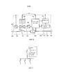
- фиг. 1 представляет схему устройства обслуживания электрической установки в соответствии с вариантом осуществления изобретения;- FIG. 1 is a diagram of a service device of an electrical installation in accordance with an embodiment of the invention;
- фиг. 2 представляет схему электрической установки, содержащей мониторинг обслуживания в соответствии с вариантом осуществления изобретения;- FIG. 2 is a diagram of an electrical installation comprising maintenance monitoring in accordance with an embodiment of the invention;
- фиг. с 3 по 5 представляют установки в соответствии с разновидностями вариантов осуществления изобретения;- FIG. 3 to 5 represent installations in accordance with varieties of embodiments of the invention;
- фиг. 6 представляет схему блока электрооборудования, выполненного с возможностью использования с устройством обслуживания электрической установки в соответствии с вариантом осуществления изобретения;- FIG. 6 is a diagram of an electrical equipment block adapted to be used with a maintenance device of an electrical installation in accordance with an embodiment of the invention;
- фиг. 7 представляет схему представления данных электрооборудования, изображающую информацию для выполнения управления обслуживанием электрической установки;- FIG. 7 is an electrical equipment data representation diagram depicting information for performing maintenance management of an electrical installation;
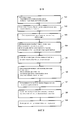
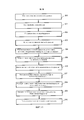
- фиг. 8 представляет первую блок-схему алгоритма способа обслуживания электрической установки в соответствии с вариантом осуществления изобретения;- FIG. 8 is a first flowchart of a method for servicing an electrical installation in accordance with an embodiment of the invention;
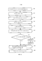
- фиг. 9 представляет вторую блок-схему алгоритма способа обслуживания электрической установки в соответствии с вариантом осуществления изобретения;- FIG. 9 is a second flowchart of a method for servicing an electrical installation in accordance with an embodiment of the invention;
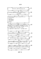
- фиг. 10 представляет блок-схему алгоритма способа для мониторинга старения электрооборудования с возможностью его связи со способом обслуживания электрической установки в соответствии с вариантом осуществления изобретения;- FIG. 10 is a flowchart of a method for monitoring aging of electrical equipment with the possibility of its connection with a method of servicing an electrical installation in accordance with an embodiment of the invention;
- фиг. 11 представляет блок-схему алгоритма способа для мониторинга селективности электрооборудования с возможностью его связи со способом обслуживания электрической установки в соответствии с вариантом осуществления изобретения.- FIG. 11 is a flowchart of a method for monitoring the selectivity of electrical equipment with the possibility of its connection with a method of servicing an electrical installation in accordance with an embodiment of the invention.
ОПИСАНИЕ ПРЕДПОЧТИТЕЛЬНЫХ ВАРИАНТОВ ОСУЩЕСТВЛЕНИЯDESCRIPTION OF PREFERRED EMBODIMENTS
Устройство для выполнения обслуживания электрической установки в соответствии с вариантом осуществления изобретения, представленным на фиг. 1, содержит модуль 1 обработки, представленный корпусом 1, содержащим схему 2 обработки, выполняющую управление вычислением и связью, а также прием и передачу данных. Модуль 1 также содержит модуль 3 хранения для хранения характеристик настройки электрооборудования, схем электрической установки, хронологии событий, возникающих в электрической установке, и/или данных вычисления селективности и старения электрооборудования. Модуль 3 хранения также хранит критерии критичности и данные, используемые в дереве решений. Эти данные могут совместно использоваться, обмениваться или копироваться между управляющей программой или другими модулями хранения. Чтобы обмениваться информацией с другими устройствами или управляющей программой, модуль обработки содержит, по меньшей мере, одну схему 4 проводной связи, и/или схему 5 беспроводной связи, и/или схему связи через сотовую телефонную сеть.A device for servicing an electrical installation in accordance with the embodiment of the invention shown in FIG. 1, comprises a
Отображение на управляющей программе может представляться с помощью глобальной или частичной монтажной схемы установки, показывающей состояния каждого блока оборудования, а также ссылочные номера, характеристики и настройки. Индикация также может выполняться на портативных компьютерах, планшетах или мобильных телефонах посредством беспроводных соединений или через сотовую телефонную сеть.The display on the control program can be represented using a global or partial installation wiring diagram showing the status of each unit of equipment, as well as reference numbers, characteristics and settings. Indications can also be carried out on laptop computers, tablets or mobile phones via wireless connections or through a cellular telephone network.
Устройство мониторинга в соответствии с вариантом осуществления изобретения содержит сеть передачи данных между блоками электрооборудования и средством обработки, чтобы передавать данные. Сеть связи может содержать модули 7, 8, 9 концентраторов линий связи для уменьшения количества входов связи у модуля обработки. Концентраторы подключаются к нескольким блокам 10, 11, 12, 13, 14 электрооборудования для передачи модулю обработки, помимо других данных, информации о рабочих условиях, типе оборудования и ссылочных номерах, группируя сообщения в канале связи.A monitoring device in accordance with an embodiment of the invention comprises a data network between the electrical units and the processing means to transmit data. The communication network may contain
Блоками электрооборудования являются, в частности, автоматические выключатели 10, 11, например, с электронными отключающими блоками или защитными реле. Блоками оборудования также могут быть модули или реле 12 детектирования утечки на землю или дифференциальные, или модули 13 измерения мощности, предпочтительно связанные с распределительными устройствами, например автоматическими выключателями или замыкателями. Также детекторы 14 короткого замыкания могут дать информацию о состоянии электрической линии или о нагрузке, чтобы предотвратить включение блока оборудования или найти электрическое короткое замыкание.The electrical units are, in particular,
Устройство обслуживания электрической установки фиг. 1 содержит измерительные входы, выполненные с возможностью подключения к измерительным датчикам физических величин окружающей среды. Они сообщают и предоставляют указания обслуживания электрической установки локальным или дистанционным способом. Измерительные датчики физических величин окружающей среды соответственно подключаются к модулю 1 обработки.The maintenance device of the electrical installation of FIG. 1 contains measurement inputs configured to connect physical variables of the environment to the measurement sensors. They communicate and provide service instructions for the electrical installation locally or remotely. Measuring sensors of physical quantities of the environment are respectively connected to the
Измерительные датчики физических величин окружающей среды содержат, в частности:Measuring sensors of physical quantities of the environment contain, in particular:
- датчик 20 температуры, предпочтительно расположенный в пространстве рядом с блоками электрооборудования, имеющими отношение к вычислению старения,a
- датчик 21 амплитуды и частоты вибраций,-
- датчик 22 влагосодержания и/или-
- датчик 23 минерализации.-
Датчик 24 с двоичным входом также выполнен с возможностью подключения к модулю 1 с целью вычисления старения. В этом случае он может подсчитывать, например, количество операций блока электрооборудования. Другие датчики 25 также выполнены с возможностью подключения к модулю 1 для содействия обслуживанию электрической установки.The
Датчики с 20 по 25 могут быть постоянными датчиками или датчиками, устанавливаемыми только тогда, когда осуществляются измерения. Кроме того, некоторые данные, например минерализация или содержание пыли, могут определяться заблаговременно или вводиться непосредственно с помощью ручного ввода.
Фиг. 2 представляет схему электрической установки 30, содержащей средство 1 обслуживания в соответствии с вариантом осуществления изобретения. На этой фигуре установка содержит 2 электрических шкафа или панели 31, 32, соответственно содержащих устройство 33 и 34 обслуживания электрической установки.FIG. 2 is a diagram of an
Шкаф 31 запитывается от трансформаторной подстанции 35, подключенной со стороны линии к электрической системе 36 питания среднего напряжения, с одной стороны и автономного генератора 37 - с другой стороны. Эти два низковольтных источника питания входят в переключатель 38 подачи питания на два направления, состоящий из двух дистанционно управляемых и механических автоматических выключателей. Со стороны нагрузки от переключателя на два направления подается питание на первую группу 39 автоматических выключателей. Затем автоматический выключатель 40 из группы 39 питает вторую группу 41 автоматических выключателей. Автоматический выключатель 42 из второй группы выполняет питание со стороны нагрузки устройства 43 преобразования и накопления электрической энергии, а затем питает третью группу 44 автоматических выключателей. Трансформаторная подстанция 35 также может содержать автоматические выключатели или разъединители со стороны линии на стороне среднего напряжения и низкого напряжения. В каждом шкафу датчики 26, измеряющие физические величины окружающей среды, могут быть общими для содействия в обслуживании электрической установки. Обслуживание электрической установки централизовано устройством 33 для шкафа 31 или направляется управляющей программе. Каждый шкаф тогда является климатической зоной для вычисления старения электрооборудования, которое в нем установлено. Каждый блок электрооборудования, содержащий устройство связи, отправляет данные о рабочих условиях вычислительному устройству 33, которое записывает все события, возникающие в этой части установки. Для других блоков оборудования вычисление их состояний также может выполняться в соответствии со значениями климатических условий, в соответствии с измерением последних и в соответствии с ранее сохраненными данными. Устройство 33 также может записывать данные, представляющие вычисление селективности.The
Шкаф 32 запитывается от трансформаторной подстанции 46, подключенной со стороны линии к электрической системе 36 питания среднего напряжения, с одной стороны и трансформатора 47, подключенного ко второй электрической системе 48 питания среднего напряжения, с другой стороны. Со стороны нагрузки от подстанции 46 и от трансформатора 47 два низковольтных источника питания входят в переключатель 49 подачи питания, состоящий из двух дистанционно управляемых и механических автоматических выключателей. Со стороны нагрузки от переключателя подается питание на первую группу 50 автоматических выключателей. Затем автоматический выключатель 51 из группы 50 запитывает вторую группу 52 автоматических выключателей. Блоки оборудования, содержащие устройство связи, отправляют управляющему устройству 34 данные о рабочих условиях. Детекторы 53 утечки на землю или повреждения изоляции монтируются на питающих линиях для нахождения поврежденных линий. Детекторы 54 короткого замыкания, смонтированные на питающих линиях, дают возможность найти повреждения линии или нагрузки. Данные, предоставленные детекторами 53 и 54, определяются в качестве условий высокой критичности в дереве решений и выполнены с возможностью блокировки восстановления работы рассматриваемой части установки. Также возможно, что детекторы 54 предоставляют данные о напряжении (усилии) для вычисления старения электрооборудования.The
Устройство 55 связи, расположенное в трансформаторной подстанции 46, также может отправлять управляющему устройству 34 данные, используемые для вычисления селективности.The
Устройства обслуживания электрической установки подключаются друг к другу с помощью сети 56 связи и к управляющей программе 57.Maintenance devices of the electrical installation are connected to each other using the
Фиг. 3 изображает другую схему части 59 установки с устройством обслуживания электрической установки, имеющую корпус 60 обработки, содержащий модуль 1 обработки и модуль 61 управления схемами связи и входами-выходами разных датчиков. Схема 61 подключается к концентраторам 8 линий связи, принимающим данные от блоков 10 - 14 электрооборудования. Концентраторы и схемы связи в блоках оборудования запитываются, например, схемами подачи питания, содержащими преобразователи 62 и 63 и линии 64 и 65.FIG. 3 depicts another diagram of an installation part 59 with an electrical installation service device having a
Фиг. 4 и 5 представляют установки в соответствии с альтернативными вариантами осуществления изобретения. На фиг. 4 части 59A, 59B, 59C установки подключаются к сети 56 связи, подключенной к управляющей программе 57. Обслуживание электрической установки соответственно является глобальным и может контролироваться центральным или удаленным оператором. Чтобы гарантировать безопасность и надежность контроля блоков электрооборудования и эффективную передачу событий, вычисление может выполняться в каждом устройстве обслуживания электрической установки. Кроме того, данные касательно схем, настроек и мониторинга состояния в составе истории событий предпочтительно обмениваются, сравниваются и объединяются в каждом модуле хранения в устройствах мониторинга.FIG. 4 and 5 represent installations in accordance with alternative embodiments of the invention. In FIG. 4 parts of the
Часть 59A установки содержит линию 70 беспроводной связи, линию 71 сотовой связи и линию 72 радиосвязи для обмена информацией с модулем 60 обработки обслуживания электрической установки. Линия 72 связи используется, например, корпусом 73, управляющим отключением или включением блока электрооборудования, например дистанционно управляемого автоматического выключателя, замыкателя или выключателя схемы переключения. Линии 70 и 71 связи используются, например, локальным оператором, чтобы быть в курсе состояния установки, данных настройки и/или данных истории событий для изменения упомянутых данных или выполнения дистанционного управления оборудованием. Модуль 74 беспроводной связи подключается к концентратору 8 для обмена информацией, например, с управляющей программой или с другими частями установки. Индикация состояния электрооборудования или электрической установки может соответственно выполняться на портативных компьютерах 76, планшетах 70 или мобильных телефонах 77 с беспроводной связью или планшетах через сотовую телефонную сеть 71.The
На фиг. 5 части 59A и 59B установки находятся, например, в одной аппаратной комнате. Некоторые линии 70, 71 связи и модули 74 могут соответственно объединяться в одной аппаратной 78. Линии 72 связи с контурами дистанционного управления связаны с каждым модулем 1 обработки. В другой аппаратной 79 другая часть 59C установки подключается к управляющей программе и к частям 59A, 59B через сеть 56 связи.In FIG. 5
Фиг. 6 изображает схему блока электрооборудования, например автоматического выключателя 100, выполненного с возможностью использования с электрической установкой в соответствии с вариантом осуществления изобретения. Автоматический выключатель содержит силовые контакты 101, подключенные к клеммам 102 с помощью силовых кабелей 103. Контакты 101 приводятся в действие механизмом 104, выполненным с возможностью управления им вручную или с помощью управляющих устройств. В автоматическом выключателе фиг. 6 механизм 104 управляется пускателем 105, например катушкой отключения повышенного напряжения и/или пониженного напряжения, отключающим реле 106, связанным с отключающим устройством 107, или устройством 108 дистанционного управления, способным размыкать и замыкать контакты 101. Электронное отключающее устройство 107 принимает сигналы, представляющие токи, протекающие в кабелях 103 и измеренные датчиками 109 тока. Другие датчики 110 подключаются к отключающему устройству 107 для предоставления информации, например локальной температуры. Автоматический выключатель также содержит модуль связи 111, подключенный к отключающему устройству и/или датчикам для предоставления данных модулю 1 для обслуживания электрической установки. Клеммы 112 дают возможность соединения некоторых элементов автоматического выключателя.FIG. 6 is a block diagram of an electrical equipment, such as a
Фиг. 7 представляет схему представления данных электрооборудования, изображающую данные обслуживания электрической установки и дерево решений. Этот тип схемы может отображаться на инструментах 57, 76, 77 мониторинга и диагностики.FIG. 7 is an electrical equipment data representation diagram depicting service data of an electrical installation and a decision tree. This type of circuit can be displayed on monitoring and
Фиг. 8 представляет первую блок-схему алгоритма способа обслуживания электрической установки, содержащей, по меньшей мере, один блок оборудования, в соответствии с вариантом осуществления изобретения. На этапе 121 данные, представляющие контролируемую электрическую установку, вводятся в базу данных, и выполняется сохранение данных, представляющих настройки и параметры блоков электрооборудования. Затем этап 122 выполняет присвоение временных меток и сохранение данных, представляющих события, возникающие в контролируемой электрической установке, в базе данных, чтобы составлять историю событий. Этап 123 выполняет детектирование неисправности или нарушения отключения, по меньшей мере, одного блока защиты электрооборудования в электрической установке. Этап 124 выполняет детектирование дополнительных неисправностей, например:FIG. 8 is a first flowchart of a method for servicing an electrical installation comprising at least one unit of equipment in accordance with an embodiment of the invention. At
- детектирование поврежденной электрической линии,- detection of a damaged electrical line,
- детектирование отключения напряжения в части электрической установки,- detection of power outages in the electrical installation,
- детектирование электрических коротких замыканий в электрической линии и/или- detection of electrical short circuits in an electrical line and / or
- детектирование утечки на землю или повреждения изоляции.- detection of earth leakage or insulation damage.
Этап 125 выполняет анализ причин неисправности электрической установки в соответствии с данными истории событий и состоянием установки. Затем этап 126 выполняет управление восстановлением работы части установки, которая находится в нерабочем состоянии, в соответствии с причинами неисправности и/или состоянием электрических линий установки, и предопределенным деревом решений. Дерево решений выполняет последовательности проверок для определения уровня критичности неисправностей и оценки риска восстановления работы установки. Заземление или постоянное короткое замыкание рассматриваются, например, как неисправности с высоким уровнем критичности, которые не разрешают автоматическое восстановление работы установки.Step 125 performs an analysis of the causes of the failure of the electrical installation in accordance with the event history data and the installation status. Then, step 126 performs recovery management of the part of the installation that is inoperative, in accordance with the causes of the malfunction and / or the state of the electrical lines of the installation, and the predetermined decision tree. The decision tree performs a series of checks to determine the level of criticality of malfunctions and assess the risk of restoration of the installation. Grounding or a permanent short circuit are considered, for example, as faults with a high level of criticality, which do not allow automatic restoration of the installation.
Этап 127 выполняет блокировку включения блока электрооборудования или питания упомянутой электрической линии до тех пор, пока детектируется короткое замыкание. Когда электрическое короткое замыкание на линии детектируется на этапе 124, этап 127 может соответственно заблокировать восстановление питания упомянутой линии до тех пор, пока остается короткое замыкание. Индикация и/или сообщение упомянутой блокировки питания упомянутой линии выполняется на этапе 129.Step 127 locks the power-on block of the electrical equipment or power of said electrical line until a short circuit is detected. When an electrical short circuit on the line is detected in
Когда отключение напряжения детектируется на этапе 124, этап 126 дает возможность определить источник упомянутого отключения напряжения в соответствии с событиями, записанными в истории событий.When a voltage failure is detected in
Анализ причин неисправности на этапе 125 содержит отбор неисправностей, вызванных электрическими повреждениями, и неисправностей, не вызванных электрическими повреждениями.The analysis of the causes of the malfunction at
Этап 128 оказывает содействие в управлении восстановлением работы установки или части установки, причем этот этап содержит, в частности:Step 128 assists in managing the recovery of the installation or part of the installation, this step comprising, in particular:
- индикацию событий,- indication of events,
- подтверждение событий, имеющих высокий уровень критичности, и- confirmation of events with a high level of criticality, and
- разрешение подачи питания электрической линии после подтверждения событий, имеющих высокий уровень критичности.- permission to supply power to the electric line after confirmation of events having a high level of criticality.
Когда неисправность касается блока электрооборудования, способ содержит, в частности:When the malfunction relates to an electrical unit, the method comprises, in particular:
- этап 125 детектирования причин отключения электрического распределительного устройства в соответствии с сообщением о его состоянии, локальным или дистанционным управлением, рабочими условиями и/или вычислением старения,-
- этап 127 блокировки ручного или автоматического повторного включения упомянутого поврежденного блока оборудования,-
- этап 129 индикации критичных причин неисправности установки и-
- этап 128 подтверждения событий, указывающих по меньшей мере одно повреждение блока оборудования.-
Фиг. 9 представляет вторую блок-схему алгоритма способа обслуживания электрической установки в соответствии с вариантом осуществления изобретения, содержащую этапы дерева решений.FIG. 9 is a second flowchart of a method for servicing an electrical installation in accordance with an embodiment of the invention, comprising steps of a decision tree.
Мониторинг в соответствии с деревом решений содержит, в частности:Monitoring in accordance with the decision tree contains, in particular:
- этап 130 мониторинга причин отключения блока электрооборудования,-
- этап 131 мониторинга внешних команд,-
- этап 132 мониторинга истории событий,-
- этап 133 мониторинга селективности и/или-
- этап 134 мониторинга данных старения.-
Затем этап 135 оценивает уровень критичности по способу с деревом решений. Этап 136 контролирует уровень критичности. Если уровень критичности высокий, то этап 137 блокирует включение блока электрооборудования или питание рассматриваемой части установки. Затем этап 138 дает возможность подтверждения критичных повреждений перед локальным или дистанционным повторным включением блока электрооборудования. Этап 139 соответственно дает возможность восстановления работы установки ручным, автоматизированным или автоматическим способом. Этот этап 139 также может содержать дистанционное управление включением блока электрооборудования или питанием электрической линии. Этап 140 выполняет передачу данных управляющей программе. Эти события также образуют часть истории событий, записанной в запоминающем устройстве.Step 135 then evaluates the criticality level of the decision tree method. Step 136 controls the level of criticality. If the level of criticality is high, then step 137 blocks the inclusion of an electrical equipment unit or power to the considered part of the installation. Then, step 138 enables critical damage to be confirmed before local or remote re-activation of the electrical unit.
Фиг. 10 представляет блок-схему алгоритма способа мониторинга старения электрооборудования с возможностью его связи со способом обслуживания электрической установки в соответствии с вариантом осуществления изобретения. Эта блок-схема алгоритма, в частности, соответствует функциям, выполненным на этапе 134, представленном на фиг. 9.FIG. 10 is a flowchart of a method for monitoring aging of electrical equipment with the possibility of its connection with a method of servicing an electrical installation in accordance with an embodiment of the invention. This flowchart, in particular, corresponds to the functions performed in
Этап 201 инициализирует мониторинг старения электрооборудования. В частности, он сохраняет характеристики каждого типа или ссылочного номера электрооборудования, пригодного для использования в установке. Этап 202 выполняет сохранение данных вычисления старения по типу оборудования. Схема вводится в однолинейном виде, задающем контактные точки со стороны линии и со стороны нагрузки, ссылочные номера каждого блока оборудования и настройки. Схема может вводиться посредством графических инструментов или импортироваться из другого программного обеспечения.Step 201 initializes the monitoring of aging of electrical equipment. In particular, it retains the characteristics of each type or reference number of electrical equipment suitable for use in the installation. Step 202 stores the aging calculation data by type of equipment. The scheme is introduced in a single-line form, specifying contact points on the line side and on the load side, the reference numbers of each equipment unit and settings. The diagram can be entered using graphical tools or imported from other software.
Этап 203 выполняет измерение и запись физических величин, представляющих условия окружающей среды. Этап 203 содержит, в частности:Step 203 measures and records physical quantities representing environmental conditions. Step 203 comprises, in particular:
- измерение и сохранение температуры с помощью датчика рядом с упомянутыми блоками электрооборудования,- measurement and storage of temperature using a sensor next to the aforementioned electrical units,
- измерение и сохранение влагосодержания,- measurement and preservation of moisture content,
- измерение и сохранение минерализации и/или- measurement and preservation of mineralization and / or
- измерение и сохранение амплитуды и частоты вибраций.- measuring and maintaining the amplitude and frequency of vibrations.
Этап 204 выполняет вычисление старения в соответствии с упомянутыми измерениями и сохраненными данными вычисления старения. На этом этапе вычисление старения содержит:Step 204 performs an aging calculation in accordance with said measurements and stored aging calculation data. At this stage, the calculation of aging contains:
- вычисление старения механической части и/или износа электрических контактов упомянутого блока оборудования,- calculating the aging of the mechanical part and / or the wear of the electrical contacts of said equipment unit,
- вычисление старения электронной части упомянутого блока оборудования и/или- calculating the aging of the electronic part of said equipment unit and / or
- вычисление старения электромагнитного пускателя упомянутого блока электрооборудования.- calculation of the aging of the electromagnetic starter of said electrical equipment block.
В конце вычисления выполняется передача и/или индикация данных, представляющих результаты вычисления старения электрооборудования.At the end of the calculation, transmission and / or indication of data representing the results of the calculation of the aging of the electrical equipment is performed.
Этап 205 определяет рабочие условия путем выполнения, в частности:Step 205 determines the operating conditions by, inter alia:
- операций счета в блоке электрооборудования,- account operations in the electrical unit,
- измерения условий операций блока электрооборудования и- measuring the operating conditions of the electrical unit and
- записи данных, представляющих операции, связанные со значениями размыкаемого тока.- records of data representing operations associated with the values of the breaking current.
Этап 205 также выполняет определение или вычисление коэффициентов ускорения старения. Этап 206 выбирает максимальный коэффициент ускорения старения из нескольких коэффициентов ускорения старения. Этап 206 дает возможность учитывать некоторую независимость коэффициентов ускорения старения. Также можно взвешивать несколько коэффициентов ускорения с общим множителем.Step 205 also performs the determination or calculation of aging acceleration factors. Step 206 selects a maximum aging acceleration coefficient from several aging acceleration factors. Step 206 makes it possible to take into account some independence of the acceleration coefficients of aging. You can also weight several acceleration factors with a common factor.
На этапе 207 способ изменяет значение коэффициента ускорения старения вследствие температуры от температурного порога. Например, свыше 85°C электронная схема может обладать гораздо большим коэффициентом ускорения старения.At
Этап 208 назначает сочетание коэффициентов ускорения старения коэффициенту ускорения старения вследствие температуры, например, температуры окружающей среды, типа электрической нагрузки, влияний синусоидальных токов и/или класса герметичности (IP) упомянутого блока электрооборудования.Step 208 assigns a combination of aging acceleration coefficients to an aging acceleration coefficient due to temperature, for example, ambient temperature, type of electrical load, effects of sinusoidal currents and / or leakproofness class (IP) of said electrical unit.
Фиг. 11 представляет блок-схему алгоритма способа мониторинга селективности электрооборудования с возможностью его связи со способом для выполнения обслуживания электрической установки в соответствии с вариантом осуществления изобретения. Эта блок-схема алгоритма, в частности, соответствует функциям, выполненным на этапе 133, представленном на фиг. 9.FIG. 11 is a flowchart of a method for monitoring the selectivity of electrical equipment with the possibility of communicating with a method for servicing an electrical installation in accordance with an embodiment of the invention. This flowchart, in particular, corresponds to the functions performed in
Этап 300 инициализирует мониторинг селективности электрооборудования. В частности, он сохраняет характеристики каждого типа или ссылочного номера электрооборудования, пригодного для использования в установке. Этап 301 дает возможность ввести схему электрической установки. Схема вводится в однолинейном виде, задающем контактные точки со стороны линии и со стороны нагрузки, а также ссылочные номера каждого блока оборудования и настройки, по меньшей мере, для оборудования без устройств связи. Схема может вводиться посредством графических инструментов или импортироваться из другого программного обеспечения.Step 300 initializes monitoring of the selectivity of electrical equipment. In particular, it retains the characteristics of each type or reference number of electrical equipment suitable for use in the installation. Step 301 makes it possible to introduce an electrical installation diagram. The scheme is introduced in a single-line form, specifying contact points on the line side and on the load side, as well as the reference numbers of each equipment unit and settings, at least for equipment without communication devices. The diagram can be entered using graphical tools or imported from other software.
Затем этап 302 выполняет передачу настроек электрооборудования между, по меньшей мере, одним блоком электрооборудования и концентратором данных или устройством обработки селективности. Этап 303 выполняет вычисление селективности электрооборудования в соответствии с упомянутыми настройками электрооборудования. Вычисление селективности учитывает данные монтажной схемы с соединениями блоков оборудования, данные настройки упомянутых блоков оборудования, введенные автоматически в результате передачи и, возможно, введенные вручную для небольших блоков оборудования без передачи. Этап 304 дает возможность выполнить настройку электрооборудования в соответствии со значениями настройки, определенными с помощью вычисления селективности. Этот этап 304 может служить для цели начальной настройки параметра или последующих настроек. Эти последующие настройки соответственно могут выполняться вручную, путем дистанционной настройки, автоматически путем загрузки значений посредством устройств связи или полуавтоматически с помощью ручных настроек, дистанционных настроек и автоматических настроек. Автоматические части настроек предпочтительно подвергаются авторизации и/или подтверждению. Этап 305 выполняет сохранение и передачу данных, представляющих новые настройки и данные селективности. Этап 306 выполняет мониторинг изменений настроек и/или изменений оборудования. Затем этап 307 проверяет совместимость между новыми настройками после изменения и вычисления селективности.Then, step 302 performs transmission of electrical equipment settings between at least one electrical equipment unit and a data concentrator or selectivity processing device. Step 303 calculates the selectivity of the electrical equipment in accordance with said electrical settings. The selectivity calculation takes into account the data of the wiring diagram with the connections of the units of equipment, the settings of the mentioned units of equipment, entered automatically as a result of the transfer and possibly manually entered for small units of equipment without transfer. Step 304 makes it possible to configure the electrical equipment in accordance with the tuning values determined by the selectivity calculation. This
В случае несовместимости этап 308 инициирует индикацию несовместимости между настройками электрооборудования и вычислением селективности. Индикация может выполняться локально и передаваться набору модулей регулировки отбора и/или управляющей программе.If incompatible, step 308 triggers an indication of incompatibility between the electrical settings and the selectivity calculation. The indication may be performed locally and transmitted to a set of selection adjustment modules and / or a control program.
На этапе 309 данные селективности передаются и вычисляются между наборами электрооборудования. На этапе 310 упомянутые данные селективности передаются управляющей программе для обзора селективности оборудования установки. Вычисление селективности может инициироваться при каждом изменении электрооборудования или при каждом изменении настроек, по меньшей мере, одного блока электрооборудования.At
В описанных выше установках линии связи между блоками оборудования описываются с помощью проводной сети и концентраторов. Эти проводные линии связи предпочтительно выполняются по стандарту производственной связи "MODBUS". Однако могут использоваться другие стандарты. Линии связи также могут быть линиями беспроводной связи типов, известных под названиями "Wi-Fi" или "ZigBee".In the settings described above, communication lines between units of equipment are described using a wired network and hubs. These wired communication lines are preferably carried out according to the production communication standard "MODBUS". However, other standards may be used. Communication lines may also be wireless communication lines of the types known as “Wi-Fi” or “ZigBee”.
Claims (59)
Applications Claiming Priority (2)
| Application Number | Priority Date | Filing Date | Title |
|---|---|---|---|
| FR1200654 | 2012-03-05 | ||
| FR1200654A FR2987690B1 (en) | 2012-03-05 | 2012-03-05 | METHOD AND DEVICE FOR MAINTENANCE OF AN ELECTRICAL INSTALLATION |
Publications (2)
| Publication Number | Publication Date |
|---|---|
| RU2013109418A RU2013109418A (en) | 2014-09-10 |
| RU2622473C2 true RU2622473C2 (en) | 2017-06-15 |
Family
ID=47720457
Family Applications (1)
| Application Number | Title | Priority Date | Filing Date |
|---|---|---|---|
| RU2013109418A RU2622473C2 (en) | 2012-03-05 | 2013-03-04 | Method and device for electric plant maintenance |
Country Status (11)
| Country | Link |
|---|---|
| US (1) | US9517534B2 (en) |
| EP (1) | EP2637071B1 (en) |
| KR (1) | KR102035351B1 (en) |
| CN (1) | CN103308794A (en) |
| AU (1) | AU2013201193B2 (en) |
| BR (1) | BR102013005184A2 (en) |
| CA (1) | CA2806987C (en) |
| ES (1) | ES2686444T3 (en) |
| FR (1) | FR2987690B1 (en) |
| IN (1) | IN2013CH00905A (en) |
| RU (1) | RU2622473C2 (en) |
Families Citing this family (16)
| Publication number | Priority date | Publication date | Assignee | Title |
|---|---|---|---|---|
| KR101426525B1 (en) * | 2014-05-07 | 2014-08-08 | (유)남양기술단 | System for monitoring substation device |
| CN105223438A (en) * | 2015-09-23 | 2016-01-06 | 四川菲博斯科技有限责任公司 | A kind of transformer online monitoring system |
| CN105241558A (en) * | 2015-10-21 | 2016-01-13 | 上海振大电器成套有限公司 | Monitoring and protection system of bus duct |
| CN105467253A (en) * | 2015-12-30 | 2016-04-06 | 普天新能源有限责任公司 | Method and system for detecting electrical equipment online |
| CN105866587B (en) * | 2016-05-04 | 2018-02-09 | 国网江苏省电力公司电力科学研究院 | A kind of power switch cabinet condition monitoring system |
| FR3053808B1 (en) * | 2016-07-07 | 2020-03-06 | Schneider Electric Industries Sas | METHOD FOR CONTROLLING AN ELECTRICAL INSTALLATION FROM A REMOTE LOCATION |
| CN106094693A (en) * | 2016-08-11 | 2016-11-09 | 江苏亿能电气有限公司 | Temperature humidity intelligent online for box switching station is monitored and Three-tele system |
| CN106208321A (en) * | 2016-08-11 | 2016-12-07 | 江苏亿能电气有限公司 | Self-powered intelligent online for box switching station is monitored and Three-tele system |
| DE102016215079A1 (en) * | 2016-08-12 | 2018-02-15 | Siemens Aktiengesellschaft | Switchgear for high voltages and method for operating the switchgear |
| CN106485866A (en) * | 2016-10-20 | 2017-03-08 | 湖南天浩智能科技有限公司 | A kind of fire power gas fire disaster intelligent monitor equipment |
| AU2018403173B2 (en) * | 2018-01-17 | 2021-07-01 | Siemens Aktiengesellschaft | Autonomous restoration of power systems after natural disasters |
| CN109713789B (en) * | 2018-12-11 | 2020-11-03 | 北京安美智享科技有限公司 | Intelligent real-time grading alarm method for substation based on BIM technology |
| CN110222044B (en) * | 2019-06-13 | 2021-07-23 | 国网浙江省电力有限公司 | Transformer substation monitoring method |
| CN112415903B (en) * | 2019-08-23 | 2023-07-21 | 松下家电(中国)有限公司 | Household appliance device, control method of remote control device and device thereof |
| CN112862372B (en) * | 2021-03-19 | 2023-04-07 | 广东电网有限责任公司 | Remote control method, device, equipment and storage medium for transformer substation disconnecting link |
| KR102506177B1 (en) * | 2022-11-17 | 2023-03-06 | (주)동화이엔지 | Ground management system for substation |
Citations (5)
| Publication number | Priority date | Publication date | Assignee | Title |
|---|---|---|---|---|
| US5032978A (en) * | 1986-05-05 | 1991-07-16 | Westinghouse Electric Co. | Status tree monitoring and display system |
| US5132920A (en) * | 1988-02-16 | 1992-07-21 | Westinghouse Electric Corp. | Automated system to prioritize repair of plant equipment |
| WO1996020439A1 (en) * | 1994-12-27 | 1996-07-04 | Siemens Aktiengesellschaft | Computer-assisted device for detecting the cause of a malfunction in a technical plant |
| DE19707065A1 (en) * | 1997-02-22 | 1998-09-03 | Daimler Benz Ag | Decision tree forming method for error localisation in technical system |
| RU2335025C1 (en) * | 2007-07-02 | 2008-09-27 | Общество с ограниченной ответственностью "Диаконт" | Method of control of hazardous technological process with non-stationary objects |
Family Cites Families (9)
| Publication number | Priority date | Publication date | Assignee | Title |
|---|---|---|---|---|
| US4853820A (en) * | 1987-05-11 | 1989-08-01 | Hendry Mechanical Works | Electronic circuit breaker systems |
| JP2001195448A (en) * | 2000-01-12 | 2001-07-19 | Sharp Corp | Usage history storage device, device and method for calculating value on the basis of use history, electrical apparatus including device, recording medium with program realizing remaining value calculating method recorded thereon and method for recycling electrical apparatus |
| EP1217486A1 (en) * | 2000-12-21 | 2002-06-26 | ABB Schweiz AG | Method for maintenance planning of technical installations |
| SE527895C2 (en) * | 2004-12-22 | 2006-07-04 | Abb Ab | Method and apparatus for controlled reconnection of circuit breakers |
| US8200372B2 (en) * | 2008-03-31 | 2012-06-12 | The Royal Institution For The Advancement Of Learning/Mcgill University | Methods and processes for managing distributed resources in electricity power generation and distribution networks |
| US8892375B2 (en) * | 2008-05-09 | 2014-11-18 | Accenture Global Services Limited | Power grid outage and fault condition management |
| US8121740B2 (en) * | 2008-12-18 | 2012-02-21 | Abb Research Ltd. | Feeder automation for an electric power distribution system |
| KR20110048771A (en) * | 2009-11-03 | 2011-05-12 | 한전케이디엔주식회사 | The engineering platform system of the electric power- telemetrics and its using method |
| WO2011156403A1 (en) * | 2010-06-07 | 2011-12-15 | Abb Research Ltd. | Systems and methods for power line event zone identification |
-
2012
- 2012-03-05 FR FR1200654A patent/FR2987690B1/en not_active Expired - Fee Related
-
2013
- 2013-02-11 EP EP13305160.7A patent/EP2637071B1/en active Active
- 2013-02-11 ES ES13305160.7T patent/ES2686444T3/en active Active
- 2013-02-12 CA CA2806987A patent/CA2806987C/en active Active
- 2013-03-01 US US13/782,291 patent/US9517534B2/en active Active
- 2013-03-01 AU AU2013201193A patent/AU2013201193B2/en not_active Ceased
- 2013-03-01 IN IN905CH2013 patent/IN2013CH00905A/en unknown
- 2013-03-04 RU RU2013109418A patent/RU2622473C2/en active
- 2013-03-04 KR KR1020130022937A patent/KR102035351B1/en active IP Right Grant
- 2013-03-04 BR BR102013005184A patent/BR102013005184A2/en not_active Application Discontinuation
- 2013-03-05 CN CN2013101390734A patent/CN103308794A/en active Pending
Patent Citations (5)
| Publication number | Priority date | Publication date | Assignee | Title |
|---|---|---|---|---|
| US5032978A (en) * | 1986-05-05 | 1991-07-16 | Westinghouse Electric Co. | Status tree monitoring and display system |
| US5132920A (en) * | 1988-02-16 | 1992-07-21 | Westinghouse Electric Corp. | Automated system to prioritize repair of plant equipment |
| WO1996020439A1 (en) * | 1994-12-27 | 1996-07-04 | Siemens Aktiengesellschaft | Computer-assisted device for detecting the cause of a malfunction in a technical plant |
| DE19707065A1 (en) * | 1997-02-22 | 1998-09-03 | Daimler Benz Ag | Decision tree forming method for error localisation in technical system |
| RU2335025C1 (en) * | 2007-07-02 | 2008-09-27 | Общество с ограниченной ответственностью "Диаконт" | Method of control of hazardous technological process with non-stationary objects |
Also Published As
| Publication number | Publication date |
|---|---|
| FR2987690A1 (en) | 2013-09-06 |
| CA2806987A1 (en) | 2013-09-05 |
| CN103308794A (en) | 2013-09-18 |
| EP2637071B1 (en) | 2018-06-27 |
| KR20130101472A (en) | 2013-09-13 |
| KR102035351B1 (en) | 2019-10-22 |
| AU2013201193B2 (en) | 2014-09-18 |
| US9517534B2 (en) | 2016-12-13 |
| RU2013109418A (en) | 2014-09-10 |
| BR102013005184A2 (en) | 2016-06-28 |
| EP2637071A1 (en) | 2013-09-11 |
| CA2806987C (en) | 2021-01-26 |
| IN2013CH00905A (en) | 2015-08-14 |
| ES2686444T3 (en) | 2018-10-17 |
| AU2013201193A1 (en) | 2013-09-19 |
| US20130231756A1 (en) | 2013-09-05 |
| FR2987690B1 (en) | 2015-07-17 |
Similar Documents
| Publication | Publication Date | Title |
|---|---|---|
| RU2622473C2 (en) | Method and device for electric plant maintenance | |
| EP2448087B1 (en) | Reliable electrical distribution system with alternate power source | |
| CN102064612B (en) | System and method for maintaining condition of relay protection | |
| KR101476234B1 (en) | Diagnostic system for substation network based on iec 61850 standard | |
| KR102145266B1 (en) | System and method for monitoring power system | |
| CN104795804A (en) | Auxiliary relay protection monitoring processing system and processing method thereof | |
| KR101422420B1 (en) | Reset type Power Switch that include ELB Auto Recovery Function | |
| CN115980438A (en) | Method and system for acquiring double-bus electric energy metering voltage of transformer substation | |
| US9793700B2 (en) | Method and device for controlling selectivity of electric equipment | |
| CN204720973U (en) | A kind of relaying protection auxiliary monitoring treatment system | |
| KR20180023661A (en) | Apparatus and method for managing power outage | |
| CN117148024B (en) | Operation fault monitoring method and system for high-voltage switch cabinet | |
| WO2023135968A1 (en) | Plant monitoring system and plant monitoring device | |
| KR101829251B1 (en) | Communication logging system and method | |
| Rui et al. | A smart grid metrics assessment of distribution automation for reliability improvement | |
| Haj-Ahmed et al. | Substation automation for replacing faulted CTs in distribution feeders | |
| Andrew et al. | Holistic approach for asset management of medium voltage switchgear in HK electric | |
| KR20220135288A (en) | High Voltage Powr Receiving Unit | |
| EP3442088A1 (en) | Electric safety and monitoring device | |
| Cardenas et al. | Experiences using intelligent line monitoring system (ILMS) and distributed fault detection based on synchrophasors | |
| CN117930079A (en) | PT disconnection warning fault remote quick positioning method and system | |
| KR20210154016A (en) | Power system fault data handling system, apparatus and method using bus protective relay | |
| JP2021184679A (en) | Distribution board system, integration system, control method of distribution board system, and program | |
| CN114899944A (en) | Communication management machine | |
| CN113812132A (en) | Monitoring device and method for monitoring |