RU2619373C1 - Method of protecting lens from optical-electronic guidance systems - Google Patents
Method of protecting lens from optical-electronic guidance systems Download PDFInfo
- Publication number
- RU2619373C1 RU2619373C1 RU2015157104A RU2015157104A RU2619373C1 RU 2619373 C1 RU2619373 C1 RU 2619373C1 RU 2015157104 A RU2015157104 A RU 2015157104A RU 2015157104 A RU2015157104 A RU 2015157104A RU 2619373 C1 RU2619373 C1 RU 2619373C1
- Authority
- RU
- Russia
- Prior art keywords
- radiation
- attack
- pulses
- laser
- optoelectronic
- Prior art date
Links
Images
Classifications
-
- F—MECHANICAL ENGINEERING; LIGHTING; HEATING; WEAPONS; BLASTING
- F41—WEAPONS
- F41H—ARMOUR; ARMOURED TURRETS; ARMOURED OR ARMED VEHICLES; MEANS OF ATTACK OR DEFENCE, e.g. CAMOUFLAGE, IN GENERAL
- F41H13/00—Means of attack or defence not otherwise provided for
- F41H13/0043—Directed energy weapons, i.e. devices that direct a beam of high energy content toward a target for incapacitating or destroying the target
- F41H13/005—Directed energy weapons, i.e. devices that direct a beam of high energy content toward a target for incapacitating or destroying the target the high-energy beam being a laser beam
- F41H13/0056—Directed energy weapons, i.e. devices that direct a beam of high energy content toward a target for incapacitating or destroying the target the high-energy beam being a laser beam for blinding or dazzling, i.e. by overstimulating the opponent's eyes or the enemy's sensor equipment
-
- F—MECHANICAL ENGINEERING; LIGHTING; HEATING; WEAPONS; BLASTING
- F41—WEAPONS
- F41B—WEAPONS FOR PROJECTING MISSILES WITHOUT USE OF EXPLOSIVE OR COMBUSTIBLE PROPELLANT CHARGE; WEAPONS NOT OTHERWISE PROVIDED FOR
- F41B15/00—Weapons not otherwise provided for, e.g. nunchakus, throwing knives
Landscapes
- Engineering & Computer Science (AREA)
- General Engineering & Computer Science (AREA)
- Physics & Mathematics (AREA)
- Optics & Photonics (AREA)
- Radar, Positioning & Navigation (AREA)
- Remote Sensing (AREA)
- Optical Radar Systems And Details Thereof (AREA)
Abstract
Description
Область техникиTechnical field
Изобретение относится к области средств радиоэлектронной борьбы (РЭБ), а более конкретно к области средств защиты объектов, например, важных промышленных предприятий, складов, центров управления, объектов военной техники и военной инфраструктуры, штабов, кораблей и т.д. от оптико-электронных систем наведения высокоточного оружия (ВТО) с полуактивными лазерными головками самонаведения (ГСН). В качестве атакующих элементов ВТО рассматриваются корректируемые бомбы, артиллерийские боеприпасы и управляемые ракеты с оптико-электронными лазерными полуактивными ГСН. Особенность таких систем состоит в том, что оптико-электронная ГСН воспринимает в качестве цели пятно лазерного излучения, которое создается лазерным целеуказателем на выбранном объекте атаки.The invention relates to the field of electronic warfare (EW), and more particularly to the field of means of protection of objects, for example, important industrial enterprises, warehouses, control centers, military equipment and military infrastructure, headquarters, ships, etc. from optoelectronic high-precision weapon guidance systems (WTO) with semi-active laser homing heads (GOS). Adjustable bombs, artillery ammunition and guided missiles with optoelectronic laser semi-active seekers are considered as attacking elements of the WTO. The peculiarity of such systems is that the optoelectronic seeker perceives as a target a spot of laser radiation that is created by a laser target designator on a selected attack object.
Уровень техникиState of the art
Известны устройства оптико-электронной защиты объектов от ВТО с лазерным наведением и реализованные при работе этих устройств способы защиты объектов [WO 2005056384, патент RU 2249172, заявка RU 99118102], основанные на обнаружении импульсов лазерного подсвета объекта обороны и излучении ответных лазерных импульсов из точек пространства, удаленных от объекта обороны на безопасное расстояние.Known devices for optoelectronic protection of objects from the WTO with laser guidance and methods of protecting objects realized during the operation of these devices [WO 2005056384, patent RU 2249172, application RU 99118102], based on the detection of laser illumination pulses of the defense object and the emission of response laser pulses from points of space remote from the object of defense at a safe distance.
Та же техническая задача решается известными способами защиты объектов путем противодействия оптико-электронным системам наведения по патенту Украины UA 53893, полезной модели RU 76187, патенту RU 2549585.The same technical problem is solved by known methods of protecting objects by counteracting optoelectronic guidance systems according to Ukrainian patent UA 53893, utility model RU 76187, patent RU 2549585.
Общим недостатком всех перечисленных способов-аналогов является их неуниверсальность, обусловленная узким спектром излучения используемых в качестве источников помехи лазеров.A common drawback of all of the above analog methods is their non-universality, due to the narrow spectrum of radiation used as sources of interference from lasers.
Для противодействия оптико-электронным лазерным системам наведения в аналогах в качестве источника направленного помехового излучения используют лазеры с длиной волны 1,06 мкм, совпадающей с длиной волны лазерного целеуказателя, с помощью которого противник обозначает цель атаки. Понятно, что в системе защиты объектов должно использоваться оптическое излучение с той же длиной волны, что и в лазерном целеуказателе. В противном случае излучение средства защиты не проходит через узкополосный интерференционный светофильтр на входе ГСН. Современное состояние лазерной техники вполне позволяет реализовать работу лазерного целеуказателя и ГСН на других длинах волн (например, на длине волны 1,54 мкм). В случае применения оптико-электронных лазерных систем наведения с другой длиной волны известные технические решения противодействия оказываются бесполезными.To counter the optoelectronic laser guidance systems, in analogs, lasers with a wavelength of 1.06 μm, which coincides with the wavelength of the laser target, with which the enemy indicates the target of the attack, are used as a source of directional interference radiation. It is clear that the object radiation protection system should use optical radiation with the same wavelength as the laser target designator. Otherwise, the radiation of the protective equipment does not pass through the narrow-band interference filter at the input of the seeker. The current state of laser technology makes it possible to realize the operation of a laser target designator and GOS at other wavelengths (for example, at a wavelength of 1.54 μm). In the case of using optoelectronic laser guidance systems with a different wavelength, the well-known technical solutions to counteraction are useless.
Т.о., известные способы не являются универсальными в отношении возможных перспективных средств нападения.Thus, the known methods are not universal in relation to possible promising means of attack.
Известен также способ защиты объектов от оптико-электронных систем наведения, предусматривающий обнаружение атаки защищаемого объекта и формирование импульсов помехового излучения в виде некогерентного оптического излучения сплошного спектра, генерируемого импульсными ксеноновыми лампами, реализованный при работе комплекса оптико-электронной защиты по полезной модели RU 91421 (принят за прототип).There is also a method of protecting objects from optoelectronic guidance systems, providing for the detection of an attack of a protected object and the formation of pulses of interfering radiation in the form of incoherent optical radiation of a continuous spectrum generated by flash xenon lamps, implemented when operating a complex of optoelectronic protection using utility model RU 91421 (adopted for the prototype).
В известном способе-прототипе в отличие от способов-аналогов ложная цель создается не излучением лазера, спектральные характеристики которого соответствуют лазерному целеуказателю системы наведения атакующего элемента ВТО, а излучением нескольких синхронно излучающих импульсных ксеноновых ламп, снабженных рассеивающей оптикой и размещаемых вне защищаемого объекта. Синхронность импульсов излучения ксеноновых ламп, обеспеченная работой датчиков облучения защищаемого объекта лазерным целеуказателем системы наведения атакующего элемента ВТО и блоком управления, позволяет импульсам всех ксеноновых ламп попасть в строб системы временной селекции атакующего элемента ВТО и сместить энергетический центр поля излучения, на который наводится оптико-электронная ГСН атакующего элемента ВТО, в сторону от защищаемого объекта.In the known prototype method, in contrast to analogue methods, a false target is created not by laser radiation, the spectral characteristics of which correspond to the laser target designator of the guidance system of the attacking element of the WTO, but by the radiation of several synchronously emitting pulsed xenon lamps equipped with scattering optics and placed outside the protected object. The synchronization of the radiation pulses of xenon lamps, provided by the operation of the radiation sensors of the protected object with a laser target designator of the guidance system of the attacking element of the WTO and the control unit, allows the pulses of all xenon lamps to enter the strobe of the temporary selection system of the attacking element of the WTO and shift the energy center of the radiation field to which the optoelectronic GOS of the attacking element of the WTO, away from the protected object.
Выполнение источников излучения для создания ложного оптического поля в стороне от прикрываемого объекта в виде импульсных газоразрядных ксеноновых ламп с кварцевой колбой, обладающих широкополосным спектром излучения, вместо узкополосных лазеров позволяет перекрыть спектры большинства существующих и перспективных систем наведения ВТО от инфракрасного до ультрафиолетового диапазона электромагнитных волн, т.е. обеспечить универсальность в отношении возможных перспективных средств нападения.The implementation of radiation sources to create a false optical field away from the object to be covered in the form of pulsed gas-discharge xenon lamps with a quartz bulb having a broadband emission spectrum, instead of narrow-band lasers, makes it possible to overlap the spectra of most existing and promising systems for guiding HTWs from the infrared to ultraviolet range of electromagnetic waves, t .e. provide versatility in relation to possible promising means of attack.
Однако известный способ-прототип (как, впрочем, и все способы-аналоги) обладает следующими недостатками:However, the known prototype method (as, incidentally, all analog methods) has the following disadvantages:
1) Ложная цель (лазерная в способах-аналогах или широкополосная нелазерная в способе-прототипе), которая реализуется в известных решениях, должна быть создана вблизи защищаемого объекта с тем расчетом, чтобы она находилась в поле зрения оптико-электронной полуактивной ГСН, а в режиме автосопровождения угловая величина поля зрения такой ГСН обычно невелика (~1…2°). На удалении около 1000 м линейное поле зрения ГСН составляет 20…50 м, и в эти размеры должны быть «вписаны» все ксеноновые лампы, используемые в способе-прототипе, вероятное отклонение атакующего элемента ВТО от энергетического центра ложной цели, безопасное удаление точки подрыва элемента ВТО от защищаемого объекта. Поэтому даже в случае штатной работы всех компонентов комплекса защиты существует вероятность повреждения или поражения защищаемого объекта атакующим элементом ВТО.1) A false target (laser in analogue methods or non-laser broadband in the prototype method), which is implemented in well-known solutions, should be created near the protected object so that it is in the field of view of the optoelectronic semi-active seeker, and in the mode auto tracking the angular magnitude of the field of view of such a seeker is usually small (~ 1 ... 2 °). At a distance of about 1000 m, the linear field of view of the GOS is 20 ... 50 m, and all xenon lamps used in the prototype method, the probable deviation of the attacking element of the WTO from the energy center of the false target, and the safe removal of the point of detonation of the element must be “entered” into these dimensions WTO from the protected object. Therefore, even in the case of regular operation of all components of the protection complex, there is a possibility of damage or damage to the protected object by the attacking element of the WTO.
2) При приближении атакующего элемента с оптико-электронной полуактивной ГСН к ложной цели в виде нескольких пространственно разнесенных импульсных ксеноновых ламп линейное поле зрения ГСН уменьшается и одна или несколько импульсных ксеноновых ламп могут оказаться вне поля зрения ГСН, что приведет к смещению энергетического центра пятна излучения, сформированного оставшимися в поле зрения лампами, в непредсказуемом направлении. Т.е. возможно смещение энергетического центра наблюдаемого ГСН поля излучения в сторону защищаемого объекта, что означает снижение надежности защиты.2) When an attacking element approaches an optoelectronic semi-active GOS to a false target in the form of several spatially separated pulsed xenon lamps, the linear field of view of the GOS decreases and one or several pulsed xenon lamps can be out of the field of view of the GOS, which will lead to a shift in the energy center of the radiation spot formed by the remaining lamps in the field of view in an unpredictable direction. Those. it is possible to shift the energy center of the observed GOS of the radiation field towards the protected object, which means a decrease in the reliability of protection.
3) В известном способе-прототипе и в способах-аналогах факт атаки на защищаемый объект и синхронизация всей дальнейшей работы определяется по наличию лазерного импульса подсвета защищаемого объекта. Появление импульсов излучения лазерного целеуказателя на объекте защиты означает, что атака уже началась и возможен дефицит времени на регистрацию и обработку лазерных импульсов, определение направления подсвета, формирование помехового излучения и, самое главное, увод атакующего элемента на ложную цель. Так, например, артиллерийские системы с использованием корректируемых снарядов с полуактивными лазерными ГСН типа «Копперхед» предусматривают коррекцию траектории лишь на конечном участке траектории, когда лазерный целеуказатель включается за несколько секунд до расчетного времени попадания снаряда в цель. В таких условиях надежность защиты объекта весьма низка.3) In the known prototype method and in analogue methods, the fact of an attack on a protected object and synchronization of all further work is determined by the presence of a laser pulse illuminating the protected object. The appearance of laser radiation pointers at the object of protection means that the attack has already begun and there may be a shortage of time for registering and processing laser pulses, determining the direction of illumination, the formation of interfering radiation and, most importantly, leading the attacker to a false target. So, for example, artillery systems using corrective shells with semi-active laser seekers of the Copperhead type provide for path correction only at the end of the path, when the laser pointer turns on a few seconds before the estimated time the projectile hits the target. In such conditions, the reliability of protection of the object is very low.
4) Еще один очень серьезный недостаток известного способа заключается в невысокой вероятности обеспечения защиты объекта, а иногда и в невозможности осуществления этой защиты.4) Another very serious drawback of the known method lies in the low probability of ensuring the protection of the object, and sometimes the impossibility of this protection.
Причина этого заключается в следующем.The reason for this is as follows.
Необходимой операцией при осуществлении известного способа, а также способов-аналогов является декодирование временной последовательности облучающих импульсов для обеспечения совпадения частотно-временной последовательности помеховых импульсов с частотно-временной последовательностью облучающих импульсов.A necessary operation in the implementation of the known method, as well as analogue methods, is to decode the time sequence of the irradiating pulses to ensure that the frequency-time sequence of the interfering pulses matches the frequency-time sequence of the irradiating pulses.
Следует отметить, что методы кодирования последовательности облучающих импульсов постоянно совершенствуются, последовательность лазерных импульсов, облучающих защищаемый объект, кодируется разными способами. В связи с этим возможны ситуации, когда декодер будет не в состоянии выполнить свою функцию. Достоверно свою функцию он может выполнить в случаях, когда последовательность облучающих лазерных импульсов имеет характер регулярно повторяющихся во времени «пачек импульсов» или импульсов, излучаемых с какой-либо постоянной частотой. Для остальных случаев декодер может не уложиться в отведенное для процесса декодирования время, либо вообще не сможет провести декодирование. Учитывая, что оптико-электронные ГСН современных средств ВТО оснащаются устройствами стробирования, обеспечивающими прием лазерных импульсов, следующих только в кодированной последовательности и не реагирующих на импульсы, следующие в другой последовательности, невозможность декодирования приведет к невозможности противодействия таким системам.It should be noted that the coding methods for the sequence of irradiating pulses are constantly being improved, the sequence of laser pulses irradiating the protected object is encoded in various ways. In this regard, there may be situations when the decoder will not be able to perform its function. It can reliably perform its function in cases where the sequence of irradiating laser pulses has the character of “bursts of pulses” that are regularly repeated in time or pulses emitted at any constant frequency. For other cases, the decoder may not meet the allotted time for the decoding process, or may not be able to decode at all. Given that the optoelectronic GOS of modern WTO devices are equipped with gating devices that receive laser pulses that follow only in an encoded sequence and do not respond to pulses that follow in a different sequence, the inability to decode will lead to the inability to counteract such systems.
Раскрытие изобретенияDisclosure of invention
Технический результат от использования предложенного способа заключается в повышении надежности защиты объектов от атаки с применением оптико-электронных систем наведения.The technical result from the use of the proposed method is to increase the reliability of protecting objects from attack using optoelectronic guidance systems.
Указанный технический результат достигается тем, что способ защиты объектов от оптико-электронных систем наведения предусматривает обнаружение атаки защищаемого объекта и формирование импульсов помехового излучения в виде некогерентного оптического излучения сплошного спектра, генерируемого импульсными ксеноновыми лампами. При этом угрозу атаки защищаемого объекта обнаруживают заблаговременно радиолокационными средствами и с их помощью определяют текущие координаты источника угрозы или атакующего элемента. Помеховое излучение формируют в виде пучка с помощью прожекторной системы и направляют непосредственно на атакующий элемент.Помеховое излучение включают до начала облучения защищаемого объекта лазерным целеуказателем оптико-электронной системы наведения, а частота повторения импульсов помехового излучения составляет не менее 100 Гц. Причем импульсы помехового направленного излучения могут быть сформированы с девиацией частоты повторения.The specified technical result is achieved by the fact that the method of protecting objects from optoelectronic guidance systems involves detecting an attack of the protected object and generating pulses of interfering radiation in the form of incoherent optical radiation of a continuous spectrum generated by xenon flash lamps. In this case, the threat of attack of the protected object is detected in advance by radar means and with their help determine the current coordinates of the threat source or the attacking element. The interference radiation is generated in the form of a beam with the aid of a searchlight system and is sent directly to the attacking element. The interference radiation is turned on prior to the irradiation of the protected object with a laser target designator of the optoelectronic guidance system, and the pulse repetition rate of the interference radiation is at least 100 Hz. Moreover, pulses of interfering directional radiation can be formed with a deviation of the repetition frequency.
Перечень фигурList of figures
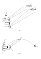
Предложенный способ поясняется чертежами, где фиг. 1 является иллюстрацией к применению способа для защиты объекта от атаки управляемыми ракетами класса «воздух-поверхность» с оптико-электронными полуактивными лазерными ГСН, а фиг. 2 - то же при атаке объекта высокоточным управляемым фугасным снарядом типа «Копперхед».The proposed method is illustrated by drawings, where FIG. 1 is an illustration of the application of a method for protecting an object from attack by guided air-to-surface missiles with optoelectronic semi-active laser seekers, and FIG. 2 - the same when attacking an object with a high-precision guided high-explosive projectile type "Copperhead".
Осуществление изобретенияThe implementation of the invention
В качестве помехового направленного излучения используется некогерентное оптическое излучение сплошного спектра, а в качестве источника такого излучения используется прожектор с импульсной ксеноновой лампой.The incoherent optical radiation of a continuous spectrum is used as the directional interference radiation, and a searchlight with a pulsed xenon lamp is used as a source of such radiation.
В соответствии с предложенным способом до начала облучения защищаемого объекта лазерным целеуказателем на оптико-электронную ГСН атакующего элемента поступает помеховое некогерентное оптическое излучение в виде направленного пучка с частотой повторения импульсов не менее 100 Гц (что заведомо существенно превышает частоту повторения импульсов лазерного целеуказателя, которая на практике составляет 20…40 Гц). В этом случае в соответствии с алгоритмом работы такой ГСН первый же полученный входной импульс излучения запускает схему селекции входных импульсов по частоте (или схему стробирования по времени), что при многократном превышении частоты помеховых импульсов по сравнению с частотой импульсов лазерного целеуказателя обеспечивает постоянный перезапуск схемы селекции и ГСН «не видит» отраженных от цели импульсов лазерного целеуказателя. Тем самым обеспечивается помеховое действие предложенного способа.In accordance with the proposed method, prior to the irradiation of the protected object with a laser target designator, an optoelectronic GOS of the attacking element receives interfering incoherent optical radiation in the form of a directed beam with a pulse repetition rate of at least 100 Hz (which obviously significantly exceeds the pulse repetition rate of the laser pointer, which in practice is 20 ... 40 Hz). In this case, in accordance with the operation algorithm of such a GOS, the first received input radiation pulse starts a frequency selection circuit of the input pulses (or a time gating circuit), which, when the frequency of the jamming pulses is many times higher than the frequency of the laser target designator, ensures a constant restart of the selection circuit and the GOS “does not see” the laser target designator pulses reflected from the target. This ensures the interference effect of the proposed method.
При этом нельзя исключить случай, когда частота повторения помеховых импульсов излучения кратна частоте повторения импульсов лазерного целеуказателя. В таком случае возможен захват оптико-электронной ГСН атакующего элемента ВТО источника импульсного помехового излучения в качестве цели и последующее наведение на этот источник. Девиация частоты повторения импульсов направленного помехового излучения исключает такую возможность.In this case, it is impossible to exclude the case when the repetition frequency of interfering radiation pulses is a multiple of the pulse repetition rate of the laser target designator. In this case, it is possible to capture the optoelectronic GOS of the attacking element of the WTO as a target of a pulsed interfering radiation source as a target and then point it at this source. The deviation of the pulse repetition rate of the directional interference radiation eliminates this possibility.
Повышение надежности защиты объектов от атаки с применением оптико-электронных систем наведения предложенным способом обусловлено тем, что в результате заблаговременного попадания на оптико-электронную ГСН атакующего элемента ВТО импульсов некогерентного широкополосного излучения с частотой более 100 Гц происходит повторяющийся перезапуск схемы временной селекции и ГСН «не видит» цель и, соответственно, не наводится на нее.The increase in the reliability of protecting objects from attack using optoelectronic guidance systems by the proposed method is due to the fact that as a result of an early hit on the optoelectronic GOS of an attacking element of the WTO pulses of incoherent broadband radiation with a frequency of more than 100 Hz, a repeated restart of the temporary selection circuit and GOS sees ”the goal and, accordingly, is not aimed at it.
Предложенный способ поясняется следующими примерами.The proposed method is illustrated by the following examples.
Пример 1. Защита от атаки управляемыми ракетами класса «воздух-поверхность» с оптико-электронными полуактивными лазерными ГСН.Example 1. Protection against attack by guided air-to-surface missiles with optoelectronic semi-active laser seekers.
Комплекс защиты объекта 1 включает в себя радиолокатор 2 воздушного обзора, вычислитель 3 и один или несколько источников направленного некогерентного помехового излучения, в качестве которых в примере используются прожектора 4 и 5 с импульсными ксеноновыми лампами, установленные с возможностью поворота по азимуту и углу места. В режиме включенной защиты радиолокатор непрерывно обследует воздушное пространство. Появление самолетов 6 и 7, представляющих потенциальную угрозу защищаемому объекту 1, обнаруживается радиолокатором задолго до момента включения лазерного целеуказателя и возможного пуска ракеты «воздух-поверхность».The protection complex of
Предположим, что в данном случае самолет 6 выполняет функции разведчика и имеет на борту лазерный целеуказатель, с помощью которого он должен подсветить выбранную цель - защищаемый объект 1. Ударный самолет 7 несет на внешней подвеске управляемые ракеты с оптико-электронными полуактивными лазерными ГСН. По сценарию такой атаки разведчик 6 при вхождении в зону пуска включает имеющийся на борту лазерный целеуказатель, наводит лазерное пятно на объект 1 и удерживает его на нем в течение всей атаки. Пилот ударного самолета 7 включает оптико-электронную ГСН ракеты и после захвата цели (информация о том, что ГСН ракеты захватила указанный лазерным целеуказателем объект 1, поступает от ГСН к пилоту) осуществляет пуск ракеты.Suppose that in this case,
В соответствии с предложенным способом при заблаговременном радиолокационном обнаружении самолетов, которые могут представлять реальную угрозу для защищаемого объекта 1 (могут быть вооружены управляемыми ракетами с полуактивными лазерными ГСН), информация об угловых координатах источников угрозы поступает на вычислитель 3, который выдает команды на включение импульсных прожекторов 4 и 5 и повороты по азимуту и углу места. Этим обеспечивается направление помехового излучения непосредственно на источники угрозы и упреждающее включение импульсной оптической широкополосной помехи.In accordance with the proposed method, with early radar detection of aircraft that can pose a real threat to the protected object 1 (can be armed with guided missiles with semi-active laser seekers), information about the angular coordinates of the threat sources is sent to
Заметим, что самолеты 6 и 7 могут приближаться к объекту 1 с различных ракурсов и неизвестно, какой из них (или оба) является носителем атакующих элементов ВТО - ракет с лазерными полуактивными ГСН. По этой причине облучению импульсным помеховым некогерентным излучением должны быть подвергнуты все участвующие в атаке на объект 1 самолеты.Note that
Источники направленного некогерентного помехового излучения 4 и 5 излучают импульсы некогерентного излучения с частотой повторения импульсов не менее 100 Гц, которые попадают на оптико-электронную полуактивную ГСН ракеты. Благодаря широкому сплошному спектру такого излучения часть падающего на ГСН потока излучения проходит через интерференционный светофильтр на входе ГСН, попадает в систему обработки и вызывает нештатную работу системы временной селекции, не давая возможности захвата цели (подсвеченного лазерным целеуказателем объекта 1). Отсутствие захвата цели при ее облучении лазерным целеуказателем, скорее всего, будет воспринято пилотом ударного самолета как отказ ГСН. В этом случае пуск ракеты представляется бессмысленным и атака на объект 1, вероятно, будет прервана.Sources of directional
Пример 2. Защита от атаки высокоточным управляемым фугасным снарядом типа «Копперхед» с оптико-электронной полуактивной лазерной ГСН.Example 2. Protection from attack by a high-precision guided high-explosive projectile type "Copperhead" with an optoelectronic semi-active laser seeker.
По сценарию такой атаки предполагается, что группа наведения скрытно приближается к объекту 1 на расстоянии нескольких километров, подготавливает аппаратуру к применению, выбирает объект для атаки и по радиоканалу дает команду на осуществление выстрела из артиллерийского орудия 8 (фиг. 2), находящегося на закрытой позиции в значительном удалении от объекта 1. С помощью аппаратуры синхронизации лазерный целеуказатель (на фиг. 2 не показан) группы наведения включается в момент нахождения управляемого снаряда 9 на конечном участке траектории за несколько секунд до расчетного времени встречи с объектом атаки. ГСН снаряда 9 захватывает пятно излучения и вырабатывает сигналы рассогласования между направлением на пятно излучения и продольной осью снаряда. Эти сигналы с учетом используемого алгоритма вызывают коррекцию траектории снаряда 9, обеспечивающую попадание в объект 1.According to the scenario of such an attack, it is assumed that the guidance group stealthily approaches
Комплекс защиты объекта 1 включает в себя радиолокатор 2 (по типу радиолокатора контрбатарейной борьбы), вычислитель 3 и один или несколько источников направленного некогерентного помехового излучения, в качестве которых в примере используется прожектор 4 с импульсной ксеноновой лампой, установленный с возможностью поворота по азимуту и углу места. При обнаружении радиолокатором 2 на среднем участке траектории летящего в направлении защищаемого объекта 1 снаряда 9 (имеющиеся разведданные позволяют предположить возможность применения высокоточных управляемых фугасных снарядов типа «Копперхед») информация о текущих угловых координатах снаряда поступает в вычислитель 3, а затем в виде команд наведения по азимуту и углу места и команды включения передается на источник помехового некогерентного направленного излучения 4, в результате чего прожектор наводится на снаряд 9 и включается. Импульсы некогерентного помехового излучения с частотой повторения импульсов не менее 100 Гц попадают на оптико-электронную полуактивную ГСН снаряда 9. Благодаря широкому сплошному спектру такого излучения часть падающего на ГСН потока излучения проходит через интерференционный светофильтр на входе ГСН, попадает в систему обработки и вызывает нештатную работу системы временной селекции, не давая возможности захвата цели (подсвеченного лазерным целеуказателем объекта 1). В результате боеприпас 9 продолжает движение по баллистической траектории без коррекции, что приводит к значительному промаху.The protection complex of
Т.о., в примере 2 высокоточный управляемый боеприпас становится обычным неуправляемым, более того, за счет раскрытых аэродинамических рулей вероятное круговое отклонение по сравнению с традиционными боеприпасами того же калибра заметно возрастает.Thus, in Example 2, high-precision guided munitions become conventional uncontrolled ones; moreover, due to the open aerodynamic rudders, the probable circular deviation increases markedly compared to traditional munitions of the same caliber.
Эффективность предложенного способа защиты объектов от атаки с применением оптико-электронных систем наведения подтверждена испытаниями, в которых оптико-электронная лазерная полуактивная ГСН располагалась на технологическом стенде на удалении около 1000 м от щита, имитирующего цель. Щит подсвечивался лазерным целеуказателем в штатном режиме работы. Источник помехового некогерентного оптического излучения в виде прожектора с импульсной ксеноновой лампой размещался на нескольких метрах от щита и находился в поле зрения оптико-электронной ГСН.The effectiveness of the proposed method of protecting objects from attack using optoelectronic guidance systems is confirmed by tests in which an optoelectronic laser semi-active seeker was located on a technological stand at a distance of about 1000 m from a shield simulating a target. The shield was highlighted with a laser target indicator in normal operation. A source of interfering incoherent optical radiation in the form of a searchlight with a pulsed xenon lamp was located a few meters from the shield and was in the field of view of the optoelectronic seeker.
В ходе испытаний сначала проверялась работа ГСН в штатном режиме: лазерный целеуказатель облучал щит, выходная информация с ГСН показывала наличие входного оптического импульсного сигнала, захват цели на автосопровождение, наличие сигналов на коррекцию траектории. При выполнении следующих реализаций обеспечивалось упреждающее включение источника импульсного помехового излучения, а затем через 2…3 с включался лазерный целеуказатель. Установлено, что в этом случае ГСН регистрирует входной оптический сигнал, но захват цели и сигналы коррекции отсутствуют.During the tests, the operation of the GOS in the normal mode was first checked: the laser target indicator irradiated the shield, the output information from the GOS showed the presence of an input optical pulse signal, target acquisition for auto tracking, the presence of signals for path correction. When performing the following implementations, a proactive inclusion of a pulsed interfering radiation source was ensured, and then after 2 ... 3 s the laser target indicator was turned on. It was found that in this case, the GOS registers an input optical signal, but there is no target acquisition and correction signals.
Эффективность способа проверена в диапазоне изменения частоты повторения импульсов помехового некогерентного оптического излучения от 100 до 2000 Гц.The effectiveness of the method is tested in the range of the pulse repetition frequency of the interfering incoherent optical radiation from 100 to 2000 Hz.
Claims (2)
Priority Applications (1)
| Application Number | Priority Date | Filing Date | Title |
|---|---|---|---|
| RU2015157104A RU2619373C1 (en) | 2015-12-30 | 2015-12-30 | Method of protecting lens from optical-electronic guidance systems |
Applications Claiming Priority (1)
| Application Number | Priority Date | Filing Date | Title |
|---|---|---|---|
| RU2015157104A RU2619373C1 (en) | 2015-12-30 | 2015-12-30 | Method of protecting lens from optical-electronic guidance systems |
Publications (1)
| Publication Number | Publication Date |
|---|---|
| RU2619373C1 true RU2619373C1 (en) | 2017-05-15 |
Family
ID=58715709
Family Applications (1)
| Application Number | Title | Priority Date | Filing Date |
|---|---|---|---|
| RU2015157104A RU2619373C1 (en) | 2015-12-30 | 2015-12-30 | Method of protecting lens from optical-electronic guidance systems |
Country Status (1)
| Country | Link |
|---|---|
| RU (1) | RU2619373C1 (en) |
Cited By (3)
| Publication number | Priority date | Publication date | Assignee | Title |
|---|---|---|---|---|
| RU2680556C1 (en) * | 2017-12-28 | 2019-02-22 | федеральное государственное бюджетное образовательное учреждение высшего образования "Московский государственный технический университет имени Н.Э. Баумана (национальный исследовательский университет)" (МГТУ им. Н.Э. Баумана) | Method of anti-electronic optical systems with laser guidance |
| RU2714825C1 (en) * | 2019-01-15 | 2020-02-19 | Михаил Викторович Яковлев | Method of counteracting deliberate impact on pilots of airliners by laser radiation |
| RU213051U1 (en) * | 2021-08-23 | 2022-08-22 | Федеральное государственное казенное военное образовательное учреждение высшего образования "Военная академия материально-технического обеспечения имени генерала армии А.В. Хрулёва" | DEVICE FOR PROTECTION OF OPTO-ELECTRONIC DEVICES OF ROBOTIC DEVICES FROM LASER RADIATION |
Citations (4)
| Publication number | Priority date | Publication date | Assignee | Title |
|---|---|---|---|---|
| GB2296078A (en) * | 1994-12-15 | 1996-06-19 | Daimler Benz Aerospace Ag | Self defence system against missiles |
| US5600434A (en) * | 1994-01-31 | 1997-02-04 | Diehl Gmbh & Co. | Apparatus for defending against an attacking missile |
| JPH1031074A (en) * | 1996-04-02 | 1998-02-03 | Trw Inc | System and method for tracking moving object |
| RU91421U1 (en) * | 2009-09-02 | 2010-02-10 | Закрытое Акционерное Общество "Интеррадиосервис" | COMPLEX OF OPTICAL-ELECTRONIC PROTECTION-COEZ |
-
2015
- 2015-12-30 RU RU2015157104A patent/RU2619373C1/en active IP Right Revival
Patent Citations (4)
| Publication number | Priority date | Publication date | Assignee | Title |
|---|---|---|---|---|
| US5600434A (en) * | 1994-01-31 | 1997-02-04 | Diehl Gmbh & Co. | Apparatus for defending against an attacking missile |
| GB2296078A (en) * | 1994-12-15 | 1996-06-19 | Daimler Benz Aerospace Ag | Self defence system against missiles |
| JPH1031074A (en) * | 1996-04-02 | 1998-02-03 | Trw Inc | System and method for tracking moving object |
| RU91421U1 (en) * | 2009-09-02 | 2010-02-10 | Закрытое Акционерное Общество "Интеррадиосервис" | COMPLEX OF OPTICAL-ELECTRONIC PROTECTION-COEZ |
Cited By (3)
| Publication number | Priority date | Publication date | Assignee | Title |
|---|---|---|---|---|
| RU2680556C1 (en) * | 2017-12-28 | 2019-02-22 | федеральное государственное бюджетное образовательное учреждение высшего образования "Московский государственный технический университет имени Н.Э. Баумана (национальный исследовательский университет)" (МГТУ им. Н.Э. Баумана) | Method of anti-electronic optical systems with laser guidance |
| RU2714825C1 (en) * | 2019-01-15 | 2020-02-19 | Михаил Викторович Яковлев | Method of counteracting deliberate impact on pilots of airliners by laser radiation |
| RU213051U1 (en) * | 2021-08-23 | 2022-08-22 | Федеральное государственное казенное военное образовательное учреждение высшего образования "Военная академия материально-технического обеспечения имени генерала армии А.В. Хрулёва" | DEVICE FOR PROTECTION OF OPTO-ELECTRONIC DEVICES OF ROBOTIC DEVICES FROM LASER RADIATION |
Similar Documents
| Publication | Publication Date | Title |
|---|---|---|
| RU2393419C2 (en) | Device of self-defense for fighting transport means or other protected objects | |
| US11181346B1 (en) | Methods for enhanced soft-kill countermeasure using a tracking radar | |
| EP2843355B1 (en) | Semi-active laser seeker synchronization | |
| GB2374134A (en) | Method and apparatus for the protection of mobile military facilities | |
| JP2018525601A (en) | A system to defend against threats | |
| RU2619373C1 (en) | Method of protecting lens from optical-electronic guidance systems | |
| EP1298408A2 (en) | Improved direction infrared counter measure | |
| US3072055A (en) | Gun launched, terminal guided projectile | |
| US7044044B2 (en) | Radio frequency triggered directed energy munition | |
| US3116039A (en) | Method of and system for guiding a missile | |
| RU2738508C1 (en) | System for observation and counteraction to unmanned aerial vehicles | |
| RU2511513C2 (en) | Method and system for aircraft protection against missiles of mobile air defence systems | |
| RU2651788C2 (en) | Device for the armored vehicles on the march protection against the impact of cluster warheads with multi-channel targets sensors | |
| RU2320949C2 (en) | Method for protection of objective from guided missiles | |
| US9915504B2 (en) | Gated conjugation laser | |
| RU2601241C2 (en) | Ac active protection method and system for its implementation (versions) | |
| IL258066A (en) | Method for protecting a missile | |
| RU76187U1 (en) | OPTICAL-ELECTRONIC GUIDANCE SYSTEM | |
| US11248879B1 (en) | Soft kill laser configuration for ground vehicle threats | |
| EP2942597B1 (en) | An active protection system | |
| RU96553U1 (en) | ON-BOARD COMPLEX OF INDIVIDUAL PROTECTION OF THE AIRCRAFT AGAINST MANAGED MISSILES WITH INFRARED Homing Heads | |
| GB2029943A (en) | Method of attacking ground targets | |
| EP3752786B1 (en) | Method and system for measuring airburst munition burst point | |
| RU2553407C1 (en) | Adaptive method of object protection against laser operated missile | |
| RU134309U1 (en) | SELF-PROPELLED INSTALLATION OF DETECTION, LIGHTING AND MONITORING OF TARGETS, GUIDING AND LAUNCHING OF MISSILE ANTI-MISSILE COMPLEX |
Legal Events
| Date | Code | Title | Description |
|---|---|---|---|
| MM4A | The patent is invalid due to non-payment of fees |
Effective date: 20181231 |
|
| NF4A | Reinstatement of patent |
Effective date: 20200211 |