RU2615980C2 - Method for transmitting information about channel state in wireless communication through feedback and appropriate device - Google Patents
Method for transmitting information about channel state in wireless communication through feedback and appropriate device Download PDFInfo
- Publication number
- RU2615980C2 RU2615980C2 RU2015112589A RU2015112589A RU2615980C2 RU 2615980 C2 RU2615980 C2 RU 2615980C2 RU 2015112589 A RU2015112589 A RU 2015112589A RU 2015112589 A RU2015112589 A RU 2015112589A RU 2615980 C2 RU2615980 C2 RU 2615980C2
- Authority
- RU
- Russia
- Prior art keywords
- csi
- message
- codebook
- information
- subset
- Prior art date
Links
Images


Classifications
-
- H—ELECTRICITY
- H04—ELECTRIC COMMUNICATION TECHNIQUE
- H04B—TRANSMISSION
- H04B7/00—Radio transmission systems, i.e. using radiation field
- H04B7/02—Diversity systems; Multi-antenna system, i.e. transmission or reception using multiple antennas
- H04B7/04—Diversity systems; Multi-antenna system, i.e. transmission or reception using multiple antennas using two or more spaced independent antennas
- H04B7/06—Diversity systems; Multi-antenna system, i.e. transmission or reception using multiple antennas using two or more spaced independent antennas at the transmitting station
- H04B7/0613—Diversity systems; Multi-antenna system, i.e. transmission or reception using multiple antennas using two or more spaced independent antennas at the transmitting station using simultaneous transmission
- H04B7/0615—Diversity systems; Multi-antenna system, i.e. transmission or reception using multiple antennas using two or more spaced independent antennas at the transmitting station using simultaneous transmission of weighted versions of same signal
- H04B7/0619—Diversity systems; Multi-antenna system, i.e. transmission or reception using multiple antennas using two or more spaced independent antennas at the transmitting station using simultaneous transmission of weighted versions of same signal using feedback from receiving side
- H04B7/0621—Feedback content
- H04B7/0626—Channel coefficients, e.g. channel state information [CSI]
-
- H—ELECTRICITY
- H04—ELECTRIC COMMUNICATION TECHNIQUE
- H04B—TRANSMISSION
- H04B7/00—Radio transmission systems, i.e. using radiation field
- H04B7/02—Diversity systems; Multi-antenna system, i.e. transmission or reception using multiple antennas
- H04B7/022—Site diversity; Macro-diversity
- H04B7/024—Co-operative use of antennas of several sites, e.g. in co-ordinated multipoint or co-operative multiple-input multiple-output [MIMO] systems
-
- H—ELECTRICITY
- H04—ELECTRIC COMMUNICATION TECHNIQUE
- H04B—TRANSMISSION
- H04B17/00—Monitoring; Testing
- H04B17/20—Monitoring; Testing of receivers
- H04B17/24—Monitoring; Testing of receivers with feedback of measurements to the transmitter
-
- H—ELECTRICITY
- H04—ELECTRIC COMMUNICATION TECHNIQUE
- H04B—TRANSMISSION
- H04B7/00—Radio transmission systems, i.e. using radiation field
- H04B7/02—Diversity systems; Multi-antenna system, i.e. transmission or reception using multiple antennas
- H04B7/04—Diversity systems; Multi-antenna system, i.e. transmission or reception using multiple antennas using two or more spaced independent antennas
- H04B7/0413—MIMO systems
- H04B7/0456—Selection of precoding matrices or codebooks, e.g. using matrices antenna weighting
- H04B7/0482—Adaptive codebooks
-
- H—ELECTRICITY
- H04—ELECTRIC COMMUNICATION TECHNIQUE
- H04L—TRANSMISSION OF DIGITAL INFORMATION, e.g. TELEGRAPHIC COMMUNICATION
- H04L1/00—Arrangements for detecting or preventing errors in the information received
- H04L1/0001—Systems modifying transmission characteristics according to link quality, e.g. power backoff
- H04L1/0023—Systems modifying transmission characteristics according to link quality, e.g. power backoff characterised by the signalling
- H04L1/0026—Transmission of channel quality indication
-
- H—ELECTRICITY
- H04—ELECTRIC COMMUNICATION TECHNIQUE
- H04L—TRANSMISSION OF DIGITAL INFORMATION, e.g. TELEGRAPHIC COMMUNICATION
- H04L5/00—Arrangements affording multiple use of the transmission path
- H04L5/003—Arrangements for allocating sub-channels of the transmission path
- H04L5/0053—Allocation of signaling, i.e. of overhead other than pilot signals
- H04L5/0057—Physical resource allocation for CQI
-
- H—ELECTRICITY
- H04—ELECTRIC COMMUNICATION TECHNIQUE
- H04L—TRANSMISSION OF DIGITAL INFORMATION, e.g. TELEGRAPHIC COMMUNICATION
- H04L5/00—Arrangements affording multiple use of the transmission path
- H04L5/0091—Signaling for the administration of the divided path
- H04L5/0094—Indication of how sub-channels of the path are allocated
-
- H—ELECTRICITY
- H04—ELECTRIC COMMUNICATION TECHNIQUE
- H04B—TRANSMISSION
- H04B7/00—Radio transmission systems, i.e. using radiation field
- H04B7/02—Diversity systems; Multi-antenna system, i.e. transmission or reception using multiple antennas
- H04B7/04—Diversity systems; Multi-antenna system, i.e. transmission or reception using multiple antennas using two or more spaced independent antennas
- H04B7/0413—MIMO systems
- H04B7/0456—Selection of precoding matrices or codebooks, e.g. using matrices antenna weighting
- H04B7/046—Selection of precoding matrices or codebooks, e.g. using matrices antenna weighting taking physical layer constraints into account
- H04B7/0469—Selection of precoding matrices or codebooks, e.g. using matrices antenna weighting taking physical layer constraints into account taking special antenna structures, e.g. cross polarized antennas into account
-
- H—ELECTRICITY
- H04—ELECTRIC COMMUNICATION TECHNIQUE
- H04L—TRANSMISSION OF DIGITAL INFORMATION, e.g. TELEGRAPHIC COMMUNICATION
- H04L25/00—Baseband systems
- H04L25/02—Details ; arrangements for supplying electrical power along data transmission lines
- H04L25/03—Shaping networks in transmitter or receiver, e.g. adaptive shaping networks
- H04L25/03891—Spatial equalizers
- H04L25/03898—Spatial equalizers codebook-based design
-
- H—ELECTRICITY
- H04—ELECTRIC COMMUNICATION TECHNIQUE
- H04L—TRANSMISSION OF DIGITAL INFORMATION, e.g. TELEGRAPHIC COMMUNICATION
- H04L5/00—Arrangements affording multiple use of the transmission path
- H04L5/0001—Arrangements for dividing the transmission path
- H04L5/0014—Three-dimensional division
- H04L5/0023—Time-frequency-space
-
- H—ELECTRICITY
- H04—ELECTRIC COMMUNICATION TECHNIQUE
- H04L—TRANSMISSION OF DIGITAL INFORMATION, e.g. TELEGRAPHIC COMMUNICATION
- H04L5/00—Arrangements affording multiple use of the transmission path
- H04L5/003—Arrangements for allocating sub-channels of the transmission path
- H04L5/0032—Distributed allocation, i.e. involving a plurality of allocating devices, each making partial allocation
- H04L5/0035—Resource allocation in a cooperative multipoint environment
Landscapes
- Engineering & Computer Science (AREA)
- Signal Processing (AREA)
- Computer Networks & Wireless Communication (AREA)
- Quality & Reliability (AREA)
- Physics & Mathematics (AREA)
- Electromagnetism (AREA)
- Mobile Radio Communication Systems (AREA)
- Mathematical Physics (AREA)
- Error Detection And Correction (AREA)
Abstract
Description
[ОБЛАСТЬ ТЕХНИКИ, К КОТОРОЙ ОТНОСИТСЯ ИЗОБРЕТЕНИЕ][FIELD OF THE INVENTION]
[1] Настоящее изобретение относится к системам беспроводной связи, а более конкретно, к способу передачи посредством обратной связи информации о состоянии канала в системе беспроводной связи и к устройству для этого.[1] The present invention relates to wireless communication systems, and more particularly, to a method for transmitting feedback about channel status in a wireless communication system and to a device for this.
[УРОВЕНЬ ТЕХНИКИ][BACKGROUND OF THE INVENTION]
[2] В качестве примера системы беспроводной связи, к которой может применяться настоящее изобретение, кратко описана система связи проекта долгосрочного развития проекта партнерства 3-го поколения (3GPP LTE) (в дальнейшем называют 'LTE').[2] As an example of a wireless communication system to which the present invention can be applied, a communication system for a long-term development project of a 3rd generation partnership project (3GPP LTE) (hereinafter referred to as 'LTE') is briefly described.
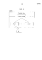
[3] Фиг. 1 - вид, схематично показывающий сетевую архитектуру E-UMTS в качестве примерной системы беспроводной связи. Усовершенствованная универсальная система мобильной связи (E-UMTS) является расширенной версией действующей универсальной системы мобильной связи (UMTS), и ее стандартизация находится в настоящее время в стадии реализации в 3GPP. E-UMTS может в общем случае упоминаться как система LTE. Для подробностей технических спецификаций UMTS и E-UMTS ссылка может, соответственно, быть сделана на выпуск 7 и выпуск 8 «3rd Generation Partnership Project; Technical Specification Group Radio Access Network».[3] FIG. 1 is a view schematically showing an E-UMTS network architecture as an exemplary wireless communication system. The Enhanced Universal Mobile Telecommunications System (E-UMTS) is an enhanced version of the current Universal Mobile Telecommunications System (UMTS), and its standardization is currently underway in 3GPP. E-UMTS may generally be referred to as an LTE system. For details of the technical specifications of UMTS and E-UMTS, reference may, respectively, be made to
[4] Ссылаясь на фиг. 1, E-UMTS включает в себя пользовательское устройство (UE), eNode B (eNB) и шлюз доступа (AG), который расположен на границе сети (усовершенствованной универсальной наземной сети радиодоступа ((E-UTRAN)) и соединен с внешней сетью. eNB могут одновременно передавать множество потоков данных для услуги широковещания, услуги многоадресной передачи и/или услуги одноадресной передачи.[4] Referring to FIG. 1, the E-UMTS includes a user equipment (UE), an eNode B (eNB), and an access gateway (AG) that is located at the edge of a network (Advanced Universal Terrestrial Radio Access Network ((E-UTRAN)) and connected to an external network. eNBs can simultaneously transmit multiple data streams for broadcast services, multicast services and / or unicast services.
[5] Одна или большее количество сот могут существовать в одном eNB. Сота конфигурируется для использования одного из диапазонов частот 1,25, 2,5, 5, 10, 20 МГц для обеспечения услуги транспортировки нисходящей линии связи или восходящей линии связи к нескольким UE. Различные соты могут конфигурироваться для обеспечения различных диапазонов частот. eNB управляет передачей и приемом данных для множества UE. eNB передает информацию планирования нисходящей линии связи для данных нисходящей линии связи для уведомления соответствующего UE о временной/частотной области передачи данных, кодировании, размере данных и информации, связанной с гибридным автоматическим запросом повторной передачи (HARQ). Кроме того, eNB передает информацию планирования восходящей линии связи для данных восходящей линии связи для информирования соответствующего UE о доступных временных/частотных областях, кодировании, размере данных и информации, связанной с HARQ. Интерфейс для передачи пользовательского трафика или трафика управления может использоваться между eNB. Базовая сеть (CN) может включать в себя AG и сетевой узел для регистрации пользователей UE. AG управляет мобильностью UE на основе области отслеживания (TA), причем одна TA состоит из множества сот.[5] One or more cells may exist in one eNB. The cell is configured to use one of the frequency ranges 1.25, 2.5, 5, 10, 20 MHz to provide downlink or uplink transport services to multiple UEs. Different cells can be configured to provide different frequency ranges. The eNB controls the transmission and reception of data for multiple UEs. The eNB transmits downlink scheduling information for the downlink data to notify the corresponding UE of the time / frequency domain of data transmission, coding, data size, and information related to the hybrid automatic retransmission request (HARQ). In addition, the eNB transmits uplink scheduling information for the uplink data to inform the corresponding UE about the available time / frequency areas, coding, data size, and HARQ related information. An interface for transmitting user traffic or control traffic may be used between the eNBs. The core network (CN) may include an AG and a network node for registering UE users. AG manages the mobility of the UE based on a tracking area (TA), wherein one TA is comprised of multiple cells.
[6] Хотя технология радиосвязи разработана до LTE, основываясь на широкополосном множественном доступе с кодовым разделением каналов (WCDMA), требования и ожидания пользователей и поставщиков услуг продолжают увеличиваться. Кроме того, так как другие технологии радиодоступа продолжают разрабатываться, новое техническое развитие требуется для будущей конкурентоспособности. Требуются уменьшение стоимости за бит, увеличение доступности услуги, гибкое использование частотного диапазона, простая структура и открытый интерфейс и приемлемая потребляемая мощность UE.[6] Although radio technology was developed prior to LTE based on wideband code division multiple access (WCDMA), the requirements and expectations of users and service providers continue to increase. In addition, as other radio access technologies continue to be developed, new technical development is required for future competitiveness. It requires cost reduction per bit, increased service availability, flexible use of the frequency range, simple structure and open interface, and acceptable power consumption of the UE.
[7] Для помощи в эффективном управлении системой беспроводной связи из eNB, UE периодически и/или не периодически сообщает eNB информацию о состоянии действующего канала. Так как информация о состоянии канала, которую сообщают, может включать в себя результаты, вычисленные с учетом различных ситуаций, необходим более эффективный способ сообщения.[7] To assist in the efficient management of the wireless communication system from the eNB, the UE periodically and / or non-periodically informs the eNB of the status of the active channel. Since the channel status information that is reported may include results calculated taking into account various situations, a more efficient reporting method is needed.
[РАСКРЫТИЕ][DISCLOSURE]
[ТЕХНИЧЕСКАЯ ЗАДАЧА][TECHNICAL PROBLEM]
[8] Целью настоящего изобретения, разработанного для решения проблемы, является обеспечение способа для сообщения информации о состоянии канала в системе беспроводной связи и устройства для этого.[8] An object of the present invention, developed to solve the problem, is to provide a method for reporting channel status information in a wireless communication system and apparatus for doing so.
[9] Специалисты оценят, что технические цели, которые могут быть достигнуты через настоящее изобретение, не ограничены тем, что было конкретно описано выше, и другие технические цели настоящего изобретения будут более ясно поняты из последующего подробного описания.[9] Those skilled in the art will appreciate that the technical objectives that can be achieved through the present invention are not limited to what has been specifically described above, and other technical objectives of the present invention will be more clearly understood from the following detailed description.
[ТЕХНИЧЕСКОЕ РЕШЕНИЕ][TECHNICAL SOLUTION]
[10] Для достижения этих и других преимуществ и в соответствии с целью настоящего изобретения, которое воплощено и в общих чертах описано, в беспроводной системе доступа, поддерживающей множество сот, способ приема информации конфигурации опорной CSI и информации конфигурации следующей CSI, которая сконфигурирована для сообщения того же самого RI (индикатора ранга), как информация конфигурации опорной CSI, приема информации первого поднабора кодовой книги предварительного кодирования для информации конфигурации опорной CSI и информации второго поднабора кодовой книги предварительного кодирования для информации конфигурации следующей CSI, причем набор RI согласно информации второго поднабора кодовой книги предварительного кодирования является тем же самым, как набор RI согласно информации первого поднабора кодовой книги предварительного кодирования, и передачи CSI, которую определяют, основываясь по меньшей мере на одной из информации первого поднабора кодовой книги предварительного кодирования и информации второго поднабора кодовой книги предварительного кодирования.[10] In order to achieve these and other advantages and in accordance with the purpose of the present invention, which is embodied and broadly described, in a wireless access system supporting multiple cells, a method of receiving reference CSI configuration information and next CSI configuration information that is configured to report the same RI (rank indicator) as the reference CSI configuration information, receiving information of a first precoding codebook subset for reference CSI configuration information and second information about the precoding codebook subset for the next CSI configuration information, wherein the RI set according to the information of the second precoding codebook subset is the same as the RI set according to the information of the first precoding codebook and transmitting the CSI that is determined based on the at least one of the information of the first subset of the precoding codebook and the information of the second subset of the precoding codebook.
[11] Согласно одному варианту осуществления информация первого поднабора кодовой книги предварительного кодирования и информация второго поднабора кодовой книги предварительного кодирования конфигурируются как растровый параметр, соответственно.[11] According to one embodiment, the information of the first subset of the precoding codebook and the information of the second subset of the precoding codebook are configured as a raster parameter, respectively.
[12] Согласно одному варианту осуществления информация первого поднабора кодовой книги предварительного кодирования и информация второго поднабора кодовой книги предварительного кодирования передаются через сигнализацию RRC (управления радиоресурсами), соответственно.[12] According to one embodiment, the information of the first subset of the precoding codebook and the information of the second subset of the precoding codebook are transmitted via RRC (Radio Resource Control) signaling, respectively.
[13] Согласно одному варианту осуществления информация конфигурации опорной CSI и информация конфигурации следующей CSI передаются через сигнализацию RRC (управления радиоресурсами), соответственно.[13] According to one embodiment, the reference CSI configuration information and the next CSI configuration information are transmitted via RRC (Radio Resource Control) signaling, respectively.
[14] Согласно одному варианту осуществления CSI включает в себя по меньшей мере одно из RI, PMI (индикатора матрицы предварительного кодирования) и CQI (индикатора качества канала).[14] According to one embodiment, the CSI includes at least one of RI, PMI (precoding matrix indicator) and CQI (channel quality indicator).
[15] Для дополнительного достижения этих и других преимуществ и в соответствии с целью настоящего изобретения в беспроводной системе доступа, поддерживающей множество сот, способ передачи информации конфигурации опорной CSI и информации конфигурации следующей CSI, которая сконфигурирована для сообщения того же самого RI (индикатора ранга), как информация конфигурации опорной CSI, передачи информации первого поднабора кодовой книги предварительного кодирования для информации конфигурации опорной CSI и информации второго поднабора кодовой книги предварительного кодирования для информации конфигурации следующей CSI, причем набор RI согласно информации второго поднабора кодовой книги предварительного кодирования является тем же самым, как набор RI согласно информации первого поднабора кодовой книги предварительного кодирования, и приема CSI, которая определена, основываясь по меньшей мере на одной из информации первого поднабора кодовой книги предварительного кодирования и информации второго поднабора кодовой книги предварительного кодирования.[15] To further achieve these and other advantages, and in accordance with an object of the present invention, in a wireless access system supporting multiple cells, a method for transmitting CSI reference configuration information and next CSI configuration information that is configured to report the same RI (rank indicator) as reference CSI configuration information, transmitting information of a first precoding codebook subset for reference CSI configuration information and second codebook subset information pre-coding for the configuration information of the next CSI, wherein the set of RI according to the information of the second subset of the precoding codebook is the same as the set of RI according to the information of the first subset of the precoding codebook and CSI reception that is determined based on at least one from the information of the first subset of the precoding codebook and the information of the second subset of the precoding codebook.
[16] Согласно одному варианту осуществления информация первого поднабора кодовой книги предварительного кодирования и информация второго поднабора кодовой книги предварительного кодирования конфигурируются как растровый параметр, соответственно.[16] According to one embodiment, the information of the first subset of the precoding codebook and the information of the second subset of the precoding codebook are configured as a raster parameter, respectively.
[17] Согласно одному варианту осуществления информация первого поднабора кодовой книги предварительного кодирования и информация второго поднабора кодовой книги предварительного кодирования передаются через сигнализацию RRC (управления радиоресурсами), соответственно.[17] According to one embodiment, the information of the first subset of the precoding codebook and the information of the second subset of the precoding codebook are transmitted via RRC (Radio Resource Control) signaling, respectively.
[18] Согласно одному варианту осуществления информация конфигурации опорной CSI и информация конфигурации следующей CSI передаются через сигнализацию RRC (управления радиоресурсами), соответственно.[18] According to one embodiment, the reference CSI configuration information and the next CSI configuration information are transmitted via RRC (Radio Resource Control) signaling, respectively.
[19] Согласно одному варианту осуществления CSI включает в себя по меньшей мере одно из RI, PMI (индикатора матрицы предварительного кодирования) и CQI (индикатора качества канала).[19] According to one embodiment, the CSI includes at least one of RI, PMI (precoding matrix indicator) and CQI (channel quality indicator).
[20] Для дополнительного достижения этих и других преимуществ и в соответствии с целью настоящего изобретения в беспроводной системе доступа, поддерживающей множество сот, мобильная станция включает в себя РЧ (радиочастотный) модуль и процессор, сконфигурированные для: приема информации конфигурации опорной CSI и информации конфигурации следующей CSI, которая сконфигурирована для сообщения того же самого RI (индикатора ранга), как информация конфигурации опорной CSI, приема информации первого поднабора кодовой книги предварительного кодирования для информации конфигурации опорной CSI и информации второго поднабора кодовой книги предварительного кодирования для информации конфигурации следующей CSI, причем набор RI согласно информации второго поднабора кодовой книги предварительного кодирования являются тем же самым, как набор RI согласно информации первого поднабора кодовой книги предварительного кодирования, и передачи CSI, определенной, основываясь по меньшей мере на одной из информации первого поднабора кодовой книги предварительного кодирования и информации второго поднабора кодовой книги предварительного кодирования.[20] To further achieve these and other advantages, and in accordance with the purpose of the present invention, in a wireless access system supporting multiple cells, the mobile station includes an RF (radio frequency) module and a processor configured to: receive reference CSI configuration information and configuration information the next CSI, which is configured to report the same RI (rank indicator) as the configuration information of the reference CSI, receiving information of the first precoding codebook subset for the configuration information of the reference CSI and the information of the second precoding codebook subset for the next CSI configuration information, wherein the RI set according to the second precoding codebook subset information is the same as the RI set according to the first precoding codebook information and transmitting A CSI determined based on at least one of the information of the first precoding codebook subset and the second a pre-coding codebook set.
[21] Дополнительно для достижения этих и других преимуществ и в соответствии с целью настоящего изобретения в беспроводной системе доступа, поддерживающей множество сот, базовая станция включает в себя РЧ (радиочастотный) модуль и процессор, сконфигурированные для: передачи информации конфигурации опорной CSI и информации конфигурации следующей CSI, которая сконфигурирована для сообщения того же самого RI (индикатора ранга), как информация конфигурации опорной CSI, передачи информации первого поднабора кодовой книги предварительного кодирования для информации конфигурации опорной CSI и информации второго поднабора кодовой книги предварительного кодирования для информации конфигурации следующей CSI, причем набор RI согласно информации второго поднабора кодовой книги предварительного кодирования являются тем же самым, как набор RI согласно информации первого поднабора кодовой книги предварительного кодирования, и приема CSI, определенной, основываясь по меньшей мере на одной из информации первого поднабора кодовой книги предварительного кодирования и информации второго поднабора кодовой книги предварительного кодирования.[21] Additionally, to achieve these and other advantages, and in accordance with the purpose of the present invention, in a wireless access system supporting multiple cells, the base station includes an RF (radio frequency) module and a processor configured to: transmit reference CSI configuration information and configuration information the next CSI that is configured to report the same RI (rank indicator) as the configuration information of the reference CSI, transmitting information of the first precoding codebook subset for the configuration information of the reference CSI and the information of the second precoding codebook subset for the next CSI configuration information, wherein the RI set according to the second precoding codebook subset information is the same as the RI set according to the first precoding codebook information and receiving CSI determined based on at least one of the information of the first subset of the precoding codebook and the information of the second Abora codebook precoding.
[БЛАГОПРИЯТНЫЕ ЭФФЕКТЫ][FAVORABLE EFFECTS]
[22] Согласно вариантам осуществления настоящего изобретения информацию о состоянии канала можно эффективно сообщать в системе беспроводной связи.[22] According to embodiments of the present invention, channel status information can be effectively reported in a wireless communication system.
[23] Специалисты оценят, что эффекты, которые могут быть достигнуты через настоящее изобретение, не ограничены тем, что было конкретно описано выше, и другие преимущества настоящего изобретения будут более ясно поняты из последующего подробного описания.[23] Those skilled in the art will appreciate that the effects that can be achieved through the present invention are not limited to what has been specifically described above, and other advantages of the present invention will be more clearly understood from the following detailed description.
[ОПИСАНИЕ ЧЕРТЕЖЕЙ][DESCRIPTION OF THE DRAWINGS]
[24] Сопроводительные чертежи, которые данный документ включает в себя для обеспечения дополнительного понимания изобретения, показывают варианты осуществления изобретения и вместе с описанием служат для объяснения принципа изобретения. На чертежах:[24] The accompanying drawings, which this document includes to provide a further understanding of the invention, show embodiments of the invention and, together with the description, serve to explain the principle of the invention. In the drawings:
[25] Фиг. 1 схематично показывает архитектуру сети E-UMTS в качестве примерной системы беспроводной связи;[25] FIG. 1 schematically shows the architecture of an E-UMTS network as an exemplary wireless communication system;
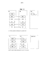
[26] Фиг. 2 показывает структуры плоскости управления и пользовательской плоскости протокола радиоинтерфейса между UE и E-UTRAN, основываясь на спецификации сети радиодоступа 3GPP;[26] FIG. 2 shows the structure of a control plane and a user plane of a radio interface protocol between a UE and an E-UTRAN, based on a specification of a 3GPP radio access network;
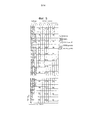
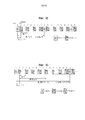
[27] Фиг. 3 показывает физические каналы, используемые в системах 3GPP, и обычный способ передачи сигналов, использующий вышеуказанные каналы;[27] FIG. 3 shows the physical channels used in 3GPP systems and a conventional signal transmission method using the above channels;
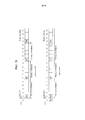
[28] Фиг. 4 показывает структуру радиокадра, используемого в системе LTE;[28] FIG. 4 shows the structure of a radio frame used in an LTE system;
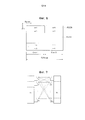
[29] Фиг. 5 показывает структуру радиокадра нисходящей линии связи, используемого в системе LTE;[29] FIG. 5 shows the structure of a downlink radio frame used in an LTE system;
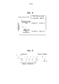
[30] Фиг. 6 показывает структуру субкадра восходящей линии связи, используемого в системе LTE;[30] FIG. 6 shows the structure of an uplink subframe used in an LTE system;
[31] Фиг. 7 показывает конфигурацию обычной системы связи MIMO;[31] FIG. 7 shows a configuration of a conventional MIMO communication system;
[32] Фиг. 8 - 11 показывают периодическое сообщение CSI;[32] FIG. 8 to 11 show a periodic CSI message;
[33] Фиг. 12 и 13 показывают процессы периодического сообщения CSI, когда используется неиерархическая кодовая книга;[33] FIG. 12 and 13 show the processes of a periodic CSI message when a non-hierarchical codebook is used;
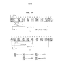
[34] Фиг. 14 показывает процесс периодического сообщения CSI, когда используется иерархическая кодовая книга;[34] FIG. 14 shows a process for periodically reporting CSI when a hierarchical codebook is used;
[35] Фиг. 15 показывает пример выполнения CoMP;[35] FIG. 15 shows an exemplary CoMP implementation;
[36] Фиг. 16 показывает операцию CoMP нисходящей линии связи;[36] FIG. 16 shows a downlink CoMP operation;
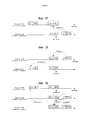
[37] Фиг. 17 показывает случай, в котором процесс сообщения типа 5 следующей CSI и процесс сообщения типа 5 опорной CSI вступают в конфликт;[37] FIG. 17 shows a case in which a
[38] Фиг. 18 - схема, показывающая другой вариант осуществления случая, в котором процесс сообщения типа 5 следующей CSI и процесс сообщения типа 5 опорной CSI вступают в конфликт;[38] FIG. 18 is a diagram showing another embodiment of a case in which a
[39] Фиг. 19 - схема, показывающая вариант осуществления, в котором три процесса CSI вступают в конфликт, как расширение фиг. 18; и[39] FIG. 19 is a diagram showing an embodiment in which three CSI processes conflict, as an extension of FIG. eighteen; and
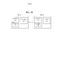
[40] Фиг. 20 - схема, показывающая БС и UE, которые могут применяться к настоящему изобретению.[40] FIG. 20 is a diagram showing a BS and a UE that may be applied to the present invention.
[НАИЛУЧШИЙ ВАРИАНТ ОСУЩЕСТВЛЕНИЯ][BEST EMBODIMENT]
[41] В дальнейшем структуры, операции и другие особенности настоящего изобретения будут легко поняты из вариантов осуществления настоящего изобретения, примеры которого описаны со ссылкой на сопроводительные чертежи. Варианты осуществления, которые будут описаны ниже, являются примерами, в которых технические особенности настоящего изобретения применяются к системам 3GPP.[41] Hereinafter, the structures, operations and other features of the present invention will be readily understood from embodiments of the present invention, examples of which are described with reference to the accompanying drawings. The embodiments that will be described below are examples in which the technical features of the present invention are applied to 3GPP systems.
[42] Хотя варианты осуществления настоящего изобретения будут описаны, основываясь на системе LTE и системе расширенного LTE (LTE-A), система LTE и система LTE-A являются только примерными, и варианты осуществления настоящего изобретения могут применяться ко всем системам связи, соответствующим вышеупомянутому определению. Кроме того, хотя варианты осуществления настоящего изобретения будут описаны в данной работе, основываясь на режиме дуплексной связи с частотным разделением каналов (FDD), режим FDD является только примерным, и варианты осуществления настоящего изобретения могут легко изменяться и применяться к режиму полу-FDD (H-FDD) или к режиму дуплексной связи с временным разделением каналов (TDD).[42] Although embodiments of the present invention will be described based on an LTE system and an extended LTE system (LTE-A), an LTE system and an LTE-A system are exemplary only, and embodiments of the present invention can be applied to all communication systems corresponding to the above. definition. In addition, although embodiments of the present invention will be described in this paper based on a frequency division duplex (FDD) mode, the FDD mode is only exemplary, and embodiments of the present invention can be easily changed and applied to the semi-FDD mode (H -FDD) or time division duplex (TDD).
[43] Фиг. 2 - вид, показывающий структуры плоскости управления и пользовательской плоскости протокола радиоинтерфейса между UE и E-UTRAN, основываясь на спецификации сети радиодоступа 3GPP. Плоскость управления относится к тракту, через который передаются сообщения управления, используемые пользовательским устройством (UE) и сетью, для управления вызовами. Пользовательская плоскость относится к тракту, через который передаются данные, сгенерированные на прикладном уровне, например, голосовые данные или пакетные данные Интернет.[43] FIG. 2 is a view showing the structure of a control plane and a user plane of a radio interface protocol between a UE and an E-UTRAN, based on a specification of a 3GPP radio access network. The control plane refers to the path through which control messages used by the user equipment (UE) and the network to manage calls are transmitted. The user plane refers to the path through which data generated at the application level, such as voice data or Internet packet data, is transmitted.
[44] Физический уровень первого уровня обеспечивает услугу перемещения информации верхнего уровня, используя физический канал. Физический уровень соединен с уровнем управления доступом к среде (MAC) верхнего уровня через транспортный канал. Данные транспортируются между уровнем MAC и физическим уровнем через транспортный канал. Данные также транспортируются между физическим уровнем передающей стороны и физическим уровнем приемной стороны через физический канал. Физический канал использует время и частоту в качестве радиоресурсов. В частности, физический канал модулируется, используя схему ортогонального множественного доступа с частотным разделением каналов (OFDMA) в нисходящей линии связи, и модулируется, используя схему множественного доступа с частотным разделением каналов с одной несущей (SC-FDMA) в восходящей линии связи.[44] The physical layer of the first level provides the service of moving information of the upper level using the physical channel. The physical layer is connected to the upper level medium access control (MAC) layer through a transport channel. Data is transported between the MAC layer and the physical layer through the transport channel. Data is also transported between the physical layer of the transmitting side and the physical layer of the receiving side through the physical channel. The physical channel uses time and frequency as radio resources. In particular, the physical channel is modulated using the downlink frequency division multiple access (OFDMA) scheme and modulated using the single carrier frequency division multiple access (SC-FDMA) scheme in the uplink.
[45] Уровень MAC второго уровня обеспечивает услугу уровня управления радиоканалом (RLC) верхнего уровня через логический канал. Уровень RLC второго уровня обеспечивает надежную передачу данных. Функция уровня RLC может осуществляться с помощью функционального блока в пределах MAC. Уровень протокола конвергенции пакетных данных (PDCP) второго уровня выполняет функцию сжатия заголовка для уменьшения ненужной управляющей информации для эффективной передачи пакета Интернет протокола (IP), такого как пакет IPv4 или IPv6 в радиоинтерфейсе, имеющем относительно узкий диапазон частот.[45] The second layer MAC layer provides the service of the upper layer radio channel control (RLC) layer through a logical channel. The second level RLC layer provides reliable data transmission. The function of the RLC layer can be performed using a function block within the MAC. The
[46] Уровень управления радиоресурсами (RRC), расположенный в самой нижней части третьего уровня, определен только в плоскости управления. Уровень RRC управляет логическими каналами, транспортными каналами и физическими каналами по отношению к конфигурации, реконфигурации и освобождению однонаправленных радиоканалов. Однонаправленные радиоканалы относятся к услуге, обеспечиваемой вторым уровнем для передачи данных между UE и сетью. Для этой цели уровень RRC UE и уровень RRC сети обмениваются сообщениями RRC. UE находится в режиме соединения RRC, если соединение RRC было установлено между уровнем RRC радиосети и уровнем RRC UE. Иначе, UE находится в режиме ожидания RRC. Уровень слоя без доступа (NAS), расположенный на верхнем уровне уровня RRC, выполняет такие функции, как управление сеансами и управление мобильностью.[46] The Radio Resource Control (RRC) layer, located at the very bottom of the third layer, is defined only in the control plane. The RRC layer controls the logical channels, transport channels, and physical channels with respect to the configuration, reconfiguration, and release of unidirectional radio channels. Unidirectional radio channels are a service provided by a second layer for transmitting data between a UE and a network. For this purpose, the RRC layer of the UE and the RRC layer of the network exchange RRC messages. The UE is in RRC connection mode if an RRC connection has been established between the RRC layer of the radio network and the RRC layer of the UE. Otherwise, the UE is in RRC standby mode. The non-access layer layer (NAS), located at the upper level of the RRC layer, performs functions such as session management and mobility management.
[47] Одна сота eNB установлена для использования одного из диапазонов частот, такого как 1,25, 2,5, 5, 10, 15 и 20 МГц, для обеспечения услуги передачи нисходящей линии связи или восходящей линии связи к множеству UE. Различные соты могут устанавливаться для обеспечения различных диапазонов частот.[47] One eNB cell is set to use one of the frequency bands, such as 1.25, 2.5, 5, 10, 15, and 20 MHz, to provide a downlink or uplink transmission service to a plurality of UEs. Different cells can be set to provide different frequency ranges.
[48] Транспортные каналы нисходящей линии связи для передачи данных от сети к UE включают в себя канал широковещания (BCH) для передачи системной информации, канал поискового вызова (PCH) для передачи сообщений поискового вызова и совместно используемый канал (SCH) нисходящей линии связи для передачи пользовательского трафика или управляющих сообщений. Трафик или управляющие сообщения услуги многопользовательской передачи или широковещания нисходящей линии связи могут передаваться через SCH нисходящей линии связи или могут передаваться через дополнительный канал многопользовательской передачи (MCH) нисходящей линии связи. В это время транспортные каналы восходящей линии связи для передачи данных от UE к сети включают в себя канал произвольного доступа (RACH) для передачи начальных управляющих сообщений и SCH восходящей линии связи для передачи пользовательского трафика или управляющих сообщений. Логические каналы, которые расположены на верхнем уровне транспортных каналов и сопоставляются с транспортными каналами, включают в себя управляющий широковещательный канал (BCCH), управляющий канал поискового вызова (PCCH), общий управляющий канал (CCCH), управляющий канал многопользовательской передачи (MCCH) и канал трафика многопользовательской передачи (MTCH).[48] Downlink transport channels for transmitting data from the network to the UE include a broadcast channel (BCH) for transmitting system information, a paging channel (PCH) for transmitting paging messages, and a downlink shared channel (SCH) for transmitting user traffic or control messages. Traffic or control messages of a downlink multiuser or broadcast service can be transmitted via a downlink SCH or can be transmitted through an additional downlink multiuser transmission channel (MCH). At this time, the uplink transport channels for transmitting data from the UE to the network include a random access channel (RACH) for transmitting initial control messages and an uplink SCH for transmitting user traffic or control messages. Logical channels that are located at the upper level of transport channels and are mapped to transport channels include a broadcast control channel (BCCH), a paging control channel (PCCH), a common control channel (CCCH), a multi-user control channel (MCCH), and a channel multiuser transmission traffic (MTCH).
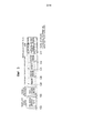
[49] Фиг. 3 - вид, показывающий физические каналы, используемые в системе 3GPP, и обычный способ передачи сигнала, использующий вышеуказанные каналы.[49] FIG. 3 is a view showing physical channels used in a 3GPP system and a conventional signal transmission method using the above channels.
[50] UE выполняет начальный поиск соты, такой как установление синхронизации с eNB, когда включается электропитание или UE входит в новую соту (этап S301). UE может принимать первичный канал синхронизации (P-SCH) и вторичный канал синхронизации (S-SCH) от eNB, устанавливать синхронизацию с eNB и получать информацию, такую как идентификатор (ID) соты. После этого UE может принимать физический канал широковещания от eNB для получения информации широковещания в пределах соты. В это время UE может принимать опорный сигнал нисходящей линии связи (RS DL) на этапе поиска первичной соты для подтверждения состояния канала нисходящей линии связи.[50] The UE performs an initial cell search, such as establishing synchronization with the eNB, when the power is turned on or the UE enters a new cell (step S301). The UE may receive a primary synchronization channel (P-SCH) and a secondary synchronization channel (S-SCH) from the eNB, establish synchronization with the eNB, and obtain information such as a cell identifier (ID). After that, the UE may receive the physical broadcast channel from the eNB to obtain broadcast information within the cell. At this time, the UE may receive the downlink reference signal (RS DL) in the primary cell search step to confirm the state of the downlink channel.
[51] После завершения поиска первичной соты UE может принимать физический управляющий канал нисходящей линии связи (PDCCH) и физический совместно используемый канал нисходящей линии связи (PDSCH) согласно информации, переносимой на PDCCH, для получения более подробной системной информации (этап S302).[51] After the search for the primary cell is completed, the UE may receive the physical downlink control channel (PDCCH) and the physical downlink shared channel (PDSCH) according to the information carried on the PDCCH to obtain more detailed system information (step S302).
[52] В это время, если UE первый раз обращается к eNB или если радиоресурсы для передачи сигнала не присутствуют, то UE может выполнять процедуру произвольного доступа (этапы S303 - S306) по отношению к eNB. Для этой цели UE может передавать определенную последовательность через физический канал произвольного доступа (PRACH) в качестве преамбулы (этапы S303 и S305) и принимать сообщение ответа на преамбулу через соответствующие PDCCH и PDSCH (этапы S304 и S306). В случае основанного на состязаниях RACH может дополнительно выполняться процедура разрешения конфликтов.[52] At this time, if the UE first accesses the eNB or if radio resources for signal transmission are not present, then the UE may perform a random access procedure (steps S303 to S306) with respect to the eNB. For this purpose, the UE may transmit a specific sequence through the physical random access channel (PRACH) as a preamble (steps S303 and S305) and receive a response message to the preamble through the corresponding PDCCH and PDSCH (steps S304 and S306). In the case of a contention-based RACH, an additional conflict resolution procedure may be performed.
[53] UE, которое выполняет вышеупомянутые процедуры, может принимать PDCCH/PDSCH (этап S307) и передавать физический совместно используемый канал восходящей линии связи (PUSCH)/физический управляющий канал восходящей линии связи (PUCCH) (этап S308) согласно обычной процедуре передачи сигнала восходящей линии связи/нисходящей линии связи. В частности, UE принимает управляющую информацию нисходящей линии связи (DCI) через PDCCH. DCI включает в себя управляющую информацию, такую как информация выделения ресурсов для UE, и имеет различные форматы согласно цели использования.[53] A UE that performs the above procedures may receive a PDCCH / PDSCH (step S307) and transmit a physical uplink shared channel (PUSCH) / physical uplink control channel (PUCCH) (step S308) according to a conventional signal transmission procedure uplink / downlink. In particular, the UE receives downlink control information (DCI) through the PDCCH. DCI includes control information, such as resource allocation information for the UE, and has various formats according to the purpose of use.
[54] В это время управляющая информация, переданная UE к eNB через восходящую линию связи или принятая UE от eNB через нисходящую линию связи, включает в себя сигнал подтверждения/отрицательного подтверждения (ACK/NACK) нисходящей линии связи/восходящей линии связи, индикатор качества канала (CQI), индекс матрицы предварительного кодирования (PMI), индикатор ранга (RI) и т.п. В случае системы LTE 3GPP, UE может передавать управляющую информацию, такую как CQI/PMI/RI, через PUSCH и/или PUCCH.[54] At this time, the control information transmitted by the UE to the eNB via the uplink or received by the UE from the eNB through the downlink includes an acknowledgment / negative acknowledgment (ACK / NACK) signal of the downlink / uplink, a quality indicator channel (CQI), precoding matrix index (PMI), rank indicator (RI), and the like. In the case of the 3GPP LTE system, the UE may transmit control information, such as CQI / PMI / RI, through the PUSCH and / or PUCCH.
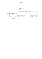
[55] Фиг. 4 - вид, показывающий структуру радиокадра, используемого в системе LTE.[55] FIG. 4 is a view showing a structure of a radio frame used in an LTE system.
[56] Ссылаясь на фиг. 4, радиокадр имеет длину 10 мс (327200 Ts) и включает в себя 10 субкадров одинакового размера. Каждый из субкадров имеет длину 1 мс и включает в себя два слота. Каждый из слотов имеет длина 0,5 мс (15360 Ts). В данном случае Ts обозначает время выборки и представляется с помощью Ts=1/(15 кГц×2048)=3,2552×10⁻⁸ (приблизительно 33 нс). Каждый слот включает в себя множество символов OFDM во временной области и включает в себя множество ресурсных блоков (RB) в частотной области. В системе LTE один ресурсный блок включает в себя 12 поднесущих ×7 (или 6) символов OFDM. Интервал времени передачи (TTI), который является единицей времени для передачи данных, может определяться в единицах из одного или большего количества субкадров. Вышеописанная структура радиокадра является просто примерной, и различные изменения могут быть сделаны в количестве субкадров, которые включает в себя радиокадр, количестве слотов, которые включают в себя субкадр, или в количестве символов OFDM, которые включает в себя слот.[56] Referring to FIG. 4, the radio frame has a length of 10 ms (327200 T s ) and includes 10 subframes of the same size. Each of the subframes is 1 ms long and includes two slots. Each of the slots has a length of 0.5 ms (15360 T s ). In this case, T s represents the sampling time and is represented by T s = 1 / (15 kHz × 2048) = 3.2552 × 10 −8 (approximately 33 ns). Each slot includes multiple OFDM symbols in the time domain and includes multiple resource blocks (RB) in the frequency domain. In an LTE system, one resource block includes 12 subcarriers × 7 (or 6) OFDM symbols. A transmission time interval (TTI), which is a unit of time for data transmission, may be determined in units of one or more subframes. The above radio frame structure is merely exemplary, and various changes can be made in the number of subframes that include the radio frame, the number of slots that include the subframe, or the number of OFDM symbols that includes the slot.
[57] Фиг. 5 - вид, показывающий каналы управления, содержащиеся в области управления одного субкадра в радиокадре нисходящей линии связи.[57] FIG. 5 is a view showing control channels contained in a control area of one subframe in a downlink radio frame.
[58] Ссылаясь на фиг. 5, один субкадр включает в себя 14 символов OFDM. Первый - третий из 14 символов OFDM могут использоваться в качестве области управления, а остальные от 13 до 11 символов OFDM могут использоваться в качестве области данных согласно конфигурации субкадра. На фиг. 5 R1-R4 представляют опорные сигналы (RS) или пилот-сигналы для антенн от 0 до 3, соответственно. RS устанавливаются в предварительно определенный шаблон в пределах субкадра независимо от области управления и области данных. Управляющие каналы выделяются ресурсам, для которых RS не выделен, в области управления. Каналы трафика выделяются ресурсам, для которых RS не выделен, в области данных. Управляющие каналы, выделенные области управления, включают в себя физический управляющий канал индикатора формата (PCFICH), физический канал индикатора гибридного ARQ (PHICH), физический управляющий канал нисходящей линии связи (PDCCH) и т.д.[58] Referring to FIG. 5, one subframe includes 14 OFDM symbols. The first to third of 14 OFDM symbols can be used as a control area, and the remaining 13 to 11 OFDM symbols can be used as a data area according to the configuration of the subframe. In FIG. 5 R1-R4 represent reference signals (RS) or pilot signals for
[59] PCFICH, физический управляющий канал индикатора формата информирует UE о количестве символов OFDM, используемых для PDCCH в субкадре. PCFICH расположен в первом символе OFDM и устанавливается перед PHICH и PDCCH. PCFICH состоит из 4 групп ресурсных элементов (REG), и каждый из REG распределяется в области управления, основываясь на идентификаторе соты. Один REG включает в себя 4 ресурсных элемента (RE). RE указывает минимальный физический ресурс, определенный как одна поднесущая × один символ OFDM. Значение PCFICH указывает значения 1-3 или значения 2-4 в зависимости от диапазона частот и модулируется с помощью квадратурной фазовой манипуляции (QPSK).[59] PCFICH, the physical format indicator control channel informs the UE of the number of OFDM symbols used for the PDCCH in the subframe. PCFICH is located in the first OFDM symbol and is set before the PHICH and PDCCH. PCFICH consists of 4 resource element groups (REGs), and each REG is distributed in the control area based on the cell identifier. One REG includes 4 resource elements (RE). RE indicates a minimum physical resource defined as one subcarrier × one OFDM symbol. The PCFICH value indicates values 1-3 or values 2-4 depending on the frequency range and is modulated by quadrature phase shift keying (QPSK).
[60] PHICH, физический канал индикатора гибридного ARQ, используется для передачи сигнала ACK/NACK HARQ для передачи восходящей линии связи. То есть PHICH указывает канал, через который передается информация ACK/NACK нисходящей линии связи для HARQ восходящей линии связи. PHICH включает в себя один REG и скремблируется определенным образом для соты. Сигнал ACK/NACK указывается с помощью 1 бит и модулируется с помощью двойной фазовой манипуляции (BPSK). Модулированный сигнал ACK/NACK расширяется с помощью коэффициента расширения (SF)=2 или 4. Множество PHICH, сопоставленных с тем же самым ресурсом, составляют группу PHICH. Количество PHICH, мультиплексируемых в группу PHICH, определяется в зависимости от величины SF. PHICH (группа) повторяется три раза для получения коэффициента усиления при разнесенном приеме в частотной области и/или во временной области.[60] PHICH, a hybrid ARQ indicator physical channel, is used to transmit an ACK / NACK HARQ signal for uplink transmission. That is, the PHICH indicates a channel through which downlink ACK / NACK information for uplink HARQ is transmitted. A PHICH includes one REG and is scrambled in a certain way for a cell. The ACK / NACK signal is indicated with 1 bit and is modulated using double phase shift keying (BPSK). The modulated ACK / NACK signal is expanded with an expansion coefficient (SF) = 2 or 4. A plurality of PHICHs mapped to the same resource constitute a PHICH group. The number of PHICHs multiplexed into a PHICH group is determined depending on the SF value. The PHICH (group) is repeated three times to obtain a diversity gain in the frequency domain and / or in the time domain.
[61] PDCCH, физический управляющий канал нисходящей линии связи, выделяется первым n символам OFDM субкадра. В этом случае n - целое число, которое больше чем 1, и указывается с помощью PCFICH. PDCCH состоит из одного или большего количества элементов управляющего канала (CCE). PDCCH информирует каждое UE или группу UE информацией, связанной с ресурсами, выделенными каналу поискового вызова (PCH) и совместно используемому каналу нисходящей линии связи (DL-SCH), с планированием предоставления ресурса восходящей линии связи, информацией гибридного автоматического запроса повторной передачи (HARQ) и т.д. Поэтому eNB и UE передают и принимают данные, кроме определенной управляющей информации или определенных данных услуги, через PDSCH.[61] A PDCCH, a physical downlink control channel, is allocated to the first n OFDM symbols of a subframe. In this case, n is an integer that is greater than 1 and is indicated by PCFICH. A PDCCH consists of one or more control channel elements (CCEs). The PDCCH informs each UE or group of UEs with information related to resources allocated to a paging channel (PCH) and a shared downlink channel (DL-SCH), with scheduling resource allocation uplink, information hybrid automatic retransmission request (HARQ) etc. Therefore, the eNB and the UE transmit and receive data, except for certain control information or certain service data, through the PDSCH.
[62] Информация, указывающая, к которому UE или к которым UE должны передаваться PDSCH данные, информация, указывающая, как UE должны принимать данные PDSCH, и информация, указывающая, как UE должны выполнять декодирование, содержится в PDCCH. Например, предполагается, что определенный PDCCH CRC-маскируется с помощью временного идентификатора радиосети (RNTI) «A» и информация о данных, которые передаются, используя радиоресурсы «B» (например, расположение частоты) и информация транспортного формата «C» (например, размер блока передачи, схема модуляции, информация кодирования и т.д.), передается через определенный субкадр. В этом случае UE, расположенное в соте, контролирует PDCCH, используя свою собственную информацию RNTI. Если присутствует одно или большее количество UE, имеющих RNTI 'A', то UE принимают PDCCH, и принимают PDSCH, обозначенный с помощью 'B' и 'C', через принятую информацию PDCCH.[62] Information indicating to which UE or to which UE PDSCH data should be transmitted, information indicating how UE should receive PDSCH data, and information indicating how UE should perform decoding are contained in the PDCCH. For example, it is assumed that a specific PDCCH CRC is masked using a temporary radio network identifier (RNTI) “A” and information about data that is transmitted using radio resources “B” (for example, frequency location) and transport format information “C” (for example, transmission block size, modulation scheme, coding information, etc.) is transmitted through a specific subframe. In this case, the UE located in the cell monitors the PDCCH using its own RNTI information. If one or more UEs having an RNTI 'A' are present, then the UEs receive a PDCCH, and receive a PDSCH indicated by 'B' and 'C' through the received PDCCH information.
[63] Фиг. 6 показывает структуру субкадра восходящей линии связи, используемого в системе LTE.[63] FIG. 6 shows the structure of an uplink subframe used in an LTE system.
[64] Ссылаясь на фиг. 6, субкадр восходящей линии связи делится на область, которой выделен PUCCH для передачи управляющей информации, и область, которой выделен PUSCH для передачи пользовательских данных. PUSCH выделяется середине субкадра, тогда как PUCCH выделяется обоим сторонам области данных в частотной области. Управляющая информация, передаваемая в PUCCH, включает в себя ACK/NACK, CQI, представляющий состояние канала нисходящей линии связи, RI для режима с множеством входов и множеством выходов (MIMO), планирующий запрос (SR), указывающий запрос о выделении ресурсов восходящей линии связи, и т.д. PUCCH UE занимает один RB на различной частоте в каждом слоте субкадра. То есть два RB, выделенные для скачкообразного изменения частоты PUCCH через границу слота. В частности, фиг. 6 показывает пример, в котором субкадру выделяются PUCCH для m=0, m=1, m=2 и m=3.[64] Referring to FIG. 6, the uplink subframe is divided into a region to which a PUCCH is allocated for transmitting control information and a region to which a PUSCH is allocated for transmitting user data. PUSCH is allocated to the middle of the subframe, while PUCCH is allocated to both sides of the data area in the frequency domain. The control information transmitted to the PUCCH includes ACK / NACK, CQI representing the state of the downlink channel, RI for multi-input and multi-output (MIMO) mode, scheduling request (SR) indicating an uplink resource allocation request , etc. A PUCCH UE occupies one RB at a different frequency in each slot of a subframe. That is, two RBs dedicated to abruptly change the PUCCH frequency across the slot boundary. In particular, FIG. 6 shows an example in which PUCCHs for m = 0, m = 1, m = 2, and m = 3 are allocated to a subframe.
[65] СИСТЕМА MIMO[65] MIMO SYSTEM
[66] В дальнейшем будет описана система MIMO. MIMO относится к способу использования множества передающих антенн и множества приемных антенн для улучшения эффективности передачи/приема данных. А именно, множество антенн используется на передающей стороне или на приемной стороне системы беспроводной связи так, чтобы емкость могла увеличиваться, и эффективность могла улучшаться. MIMO в данном раскрытии может также упоминаться как 'с множеством антенн'.[66] A MIMO system will be described hereinafter. MIMO relates to a method of using multiple transmit antennas and multiple receive antennas to improve data transmission / reception efficiency. Namely, a plurality of antennas are used on the transmitting side or on the receiving side of the wireless communication system so that the capacitance can increase and the efficiency can be improved. MIMO in this disclosure may also be referred to as 'multi-antenna'.
[67] Технология MIMO не зависит от тракта одной антенны для приема всего сообщения. Вместо этого технология MIMO собирает фрагменты данных, принятые через несколько антенн, объединяет фрагменты данных и формирует законченные данные. Использование технологии MIMO может увеличивать зону действия системы при увеличении скорости передачи данных в пределах площади соты определенного размера или обеспечении определенной скорости передачи данных. Технология MIMO может широко использоваться в терминалах мобильной связи и узлах ретранслятора. Технология MIMO может преодолевать ограничения ограниченного количества передаваемых данных систем мобильной связи, основанных на одной антенне.[67] MIMO technology is independent of a single antenna path for receiving the entire message. Instead, MIMO technology collects pieces of data received through multiple antennas, combines pieces of data, and generates complete data. Using MIMO technology can increase the coverage of the system by increasing the data rate within a cell area of a certain size or by providing a certain data rate. MIMO technology can be widely used in mobile communication terminals and relay nodes. MIMO technology can overcome the limitations of the limited amount of transmitted data of mobile communication systems based on a single antenna.
[68] Конфигурация обычной системы связи MIMO показана на фиг. 7. Передающая сторона оборудована NT передающими (Tx) антеннами, а приемная сторона оборудована NR приемными (Rx) антеннами. Если множество антенн используется и на передающей стороне, и на приемной стороне, то емкость передачи канала теоретически увеличивается, в отличие от случая, когда множество антенн используют только или на передающей стороне, или на приемной стороне. Увеличение емкости передачи канала пропорционально количеству антенн, таким образом улучшая скорость передачи и эффективность использования частоты. Если максимальная скорость передачи, используя сигнальную антенну, равна R0, то скорость передачи, используя множество антенн, может теоретически увеличиваться в соответствии с произведением максимальной скорости передачи R0 на приращение Ri скорости. Приращение Ri скорости представлено следующим уравнением 1, где Ri - наименьшее из ΝT и NR.[68] The configuration of a conventional MIMO communication system is shown in FIG. 7. The transmitting side is equipped with N T transmitting (Tx) antennas, and the receiving side is equipped with N R receiving (Rx) antennas. If multiple antennas are used on both the transmitting side and the receiving side, then the transmission capacity of the channel theoretically increases, in contrast to the case when the multiple antennas are used only on the transmitting side or on the receiving side. The increase in channel transmission capacity is proportional to the number of antennas, thereby improving the transmission speed and frequency efficiency. If the maximum transmission rate using a signal antenna is R 0 , then the transmission rate using a plurality of antennas can theoretically increase in accordance with the product of the maximum transmission rate R 0 and the increment R i of the speed. The increment R i of the speed is represented by the
[69] [Уравнение 1][69] [Equation 1]
![]()
![]()
[71] Например, в системе связи MIMO, использующей четыре Tx антенны и четыре Rx антенны, возможно теоретически получить скорость передачи в четыре раза больше, чем в системе с одной антенной. После того, как теоретическое увеличение емкости системы MIMO было первый раз продемонстрировано в середине 1990-х, были разработаны различные методики значительного улучшения скорости передачи данных. Несколько из этих методик уже внедрены в множество стандартов беспроводной связи, включающих в себя, например, 3-е поколение мобильной связи и беспроводные локальные сети следующего поколения.[71] For example, in a MIMO communication system using four Tx antennas and four Rx antennas, it is theoretically possible to obtain a transmission speed four times higher than in a single antenna system. After the theoretical increase in capacity of a MIMO system was first demonstrated in the mid-1990s, various techniques were developed to significantly improve the data transfer rate. Several of these techniques have already been implemented in many wireless standards, including, for example, 3rd generation mobile communications and next-generation wireless LANs.
[72] Активные исследования, относящиеся к технологии MIMO, до настоящего времени были сосредоточены на множестве различных аспектов, которые включают в себя исследования в сфере теории информации, относящееся к вычислению емкости связи MIMO в средах с различными каналами и в средах с множественным доступом, исследования в сфере измерении беспроводного канала и моделей, полученных из систем MIMO, и исследования в сфере технологии обработки сигналов пространство-время для улучшения надежности передачи и скорости передачи.[72] Active research related to MIMO technology has so far focused on many different aspects, which include information theory research related to calculating the MIMO communication capacity in multi-channel and multi-access environments, research in the field of wireless channel measurement and models obtained from MIMO systems, and research in the field of space-time signal processing technology to improve transmission reliability and transmission speed.
[73] Для подробного описания способа связи в системе MIMO ниже приведена его математическая модель. Как показано на фиг. 7, предполагается, что присутствуют ΝT Tx антенн и NR Rx антенн. В случае сигнала передачи максимальное количество передаваемых частей информаций равно ΝT при условии, что используются NT Tx антенн, так что информация передачи может быть представлена вектором, представленным следующим уравнением 2:[73] For a detailed description of the communication method in the MIMO system, its mathematical model is given below. As shown in FIG. 7, it is assumed that Ν T Tx antennas and N R Rx antennas are present. In the case of a transmission signal, the maximum number of transmitted pieces of information is Ν T , provided that N T Tx antennas are used, so that the transmission information can be represented by a vector represented by the following equation 2:
[74] [Уравнение 2][74] [Equation 2]

[76] В это время отдельные части S1, S2, …, SNT информации передачи могут иметь различные мощности передачи. В этом случае, если отдельные мощности передачи обозначены с помощью P1, P2, …, PNT, то информация передачи, имеющая скорректированные мощности передачи, может быть представлена вектором, показанным в следующем уравнении 3:[76] At this time, the individual pieces of transmission information S 1 , S 2 , ..., S NT can have different transmission powers. In this case, if the individual transmit powers are indicated by P 1 , P 2 , ..., P NT , then the transmission information having the adjusted transmit powers may be represented by the vector shown in the following equation 3:
[77] [Уравнение 3][77] [Equation 3]
![]()
![]()
[79] Вектор информации передачи, управляемый мощностью передачи, может быть выражен следующим образом, используя диагональную матрицу P мощности передачи:[79] The transmit information vector controlled by the transmit power can be expressed as follows using the diagonal transmit power matrix P:
[80] [Уравнение 4][80] [Equation 4]

[82] *78[82] * 78
[83] Ντ сигналов передачи x1, x2, …, xΝT для фактической передачи могут конфигурироваться с помощью умножения управляемого мощностью передачи информационного вектора Ŝ на матрицу W весов. В этом случае матрица весов настраивается для распределения должным образом информации передачи отдельным антеннам согласно ситуации в канале передачи. Сигналы передачи x1, x2, …, xΝT могут быть представлены с помощью следующего уравнения 5, используя вектор X. В уравнении 5 Wij является весом между i-й Tx антенной и j-й информацией, и W является матрицей весов, которая может также упоминаться как матрица предварительного кодирования.[83] Ντ transmission signals x 1, x 2, ..., x ΝT for actual transmission may be configured managed by multiplying a transmission power information vector Ŝ by the matrix of weights W. In this case, the weight matrix is configured to properly distribute the transmission information to the individual antennas according to the situation in the transmission channel. The transmission signals x 1 , x 2 , ..., x Ν T can be represented using the
[84] [Уравнение 5][84] [Equation 5]

[86] В общем случае физическим значением ранга матрицы канала может быть максимальное количество различных частей информации, которые могут передаваться в данном канале. Соответственно, так как ранг матрицы канала определяется, как наименьшее из количества строк или столбцов, которые независимы друг от друга, ранг матрицы не больше количества строк или столбцов. Ранг матрицы H канала, rank(H), ограничен следующим образом.[86] In the General case, the physical value of the rank of the channel matrix can be the maximum number of different pieces of information that can be transmitted in this channel. Accordingly, since the rank of the channel matrix is defined as the smallest of the number of rows or columns that are independent of each other, the rank of the matrix is not greater than the number of rows or columns. The rank of the channel matrix H, rank (H), is limited as follows.
[87] [Уравнение 6][87] [Equation 6]
![]()
![]()
[89] Каждая единица различной информации, передаваемой с использованием технологии MIMO, определяется как 'поток передачи' или просто 'поток'. 'Поток' может упоминаться как 'уровень'. Количество потоков передачи не больше ранга канала, который является максимальным количеством различных частей передаваемой информации. Соответственно, матрица H канала может быть показана с помощью следующего уравнения 7:[89] Each unit of various information transmitted using MIMO technology is defined as a 'stream of transmission' or simply a 'stream'. 'Stream' may be referred to as a 'level'. The number of transmission streams is not more than the rank of the channel, which is the maximum number of different parts of the transmitted information. Accordingly, the channel matrix H can be shown using the following equation 7:
[90] [Уравнение 7][90] [Equation 7]
![]()
![]()
[92] Нужно отметить, что один поток может передаваться через одну или большее количество антенн.[92] It should be noted that one stream may be transmitted through one or more antennas.
[93] Могут быть различные способы предоставления возможности, чтобы один или большее количество потоков соответствовали множеству антенн. Эти способы могут быть описаны следующим образом согласно типам технологии MIMO. Случай, когда один поток передается через множество антенн, может называться пространственным разнесением, а случай, когда множество потоков передаются через множество антенн, может называться пространственным мультиплексированием. Также можно конфигурировать гибридную схему пространственного разнесения и пространственного мультиплексирования.[93] There may be various ways to enable one or more streams to correspond to multiple antennas. These methods can be described as follows according to types of MIMO technology. The case where one stream is transmitted through multiple antennas may be referred to as spatial diversity, and the case where multiple streams are transmitted through multiple antennas may be referred to as spatial multiplexing. You can also configure a hybrid scheme of spatial diversity and spatial multiplexing.
[94] ОБРАТНАЯ СВЯЗЬ CSI[94] FEEDBACK
[95] Далее приведено описание сообщения информации о состоянии канала (CSI). В текущем стандарте LTE схема передачи MIMO категоризируется на MIMO без обратной связи, которая работает без CSI, и MIMO с обратной связью, которая работает, основываясь на CSI. В частности, согласно системе MIMO с обратной связью, каждый из eNB и UE может иметь возможность выполнять формирование диаграммы направленности, основываясь на CSI, для получения усиления при мультиплексировании антенн MIMO. Для получения CSI от UE, eNB назначает PUCCH или PUSCH для передачи команды к UE для передачи посредством обратной связи CSI для сигнала нисходящей линии связи.[95] The following is a description of a Channel Status Information (CSI) message. In the current LTE standard, a MIMO transmission scheme is categorized as MIMO without feedback, which works without CSI, and MIMO with feedback, which works based on CSI. In particular, according to a feedback MIMO system, each of the eNBs and the UEs may be able to perform beamforming based on CSI to obtain gain when multiplexing the MIMO antennas. In order to obtain CSI from the UE, the eNB assigns a PUCCH or PUSCH for transmitting a command to the UE for transmission via CSI feedback for the downlink signal.
[96] CSI делится на информацию трех типов: индикатор ранга (RI), индекс матрицы предварительного кодирования (PMI) и индикатор качества канала (CQI). Первая, RI, является информацией, относящейся к рангу канала, которая описана выше, и она указывает количество потоков, которые могут приниматься через тот же самый частотно-временной ресурс. Так как RI определяется с помощью медленного замирания в канале, она может в общем случае передаваться посредством обратной связи в цикле, который дольше, чем цикл PMI или CQI.[96] CSI is divided into three types of information: rank indicator (RI), precoding matrix index (PMI), and channel quality indicator (CQI). The first, RI, is the channel rank information described above, and it indicates the number of streams that can be received through the same time-frequency resource. Since RI is determined by slow fading in a channel, it can generally be transmitted via feedback in a cycle that is longer than a PMI or CQI cycle.
[97] Вторая, PMI, является значением, отражающим пространственную характеристику канала, и она указывает индекс матрицы предварительного кодирования для eNB, которому UE отдает предпочтение, основываясь на показателе отношения сигнала к помехам плюс шум (SINR). Наконец, CQI является информацией, указывающей интенсивность канала, и она указывает SINR приема, доступное, когда eNB использует PMI.[97] The second, PMI, is a value reflecting the spatial characteristic of the channel, and it indicates the index of the precoding matrix for the eNB, to which the UE prefers based on the signal-to-noise plus noise ratio (SINR). Finally, the CQI is information indicating channel strength, and it indicates the reception SINR available when the eNB uses the PMI.
[98] В развитой системе связи, такой как система LTE-A, дополнительно получается многопользовательское разнесение, используя многопользовательскую MIMO (MU-MIMO). Так как помехи между UE мультиплексируются в области антенн, существующей в схеме MU-MIMO, на точность CSI могут очень сильно влиять не только помехи UE, которое сообщает CSI, но также и помехи другого мультиплексируемого UE. Следовательно, для правильного выполнения операции MU-MIMO необходимо сообщать CSI, имеющую точность выше, чем точность схемы однопользовательского MIMO (SU-MIMO).[98] In a developed communication system, such as an LTE-A system, multi-user diversity is further obtained using multi-user MIMO (MU-MIMO). Since the interference between the UEs is multiplexed in the antenna area existing in the MU-MIMO scheme, not only the interference of the UE that reports the CSI, but also the interference of another multiplexed UE can greatly influence the accuracy of the CSI. Therefore, for the MU-MIMO operation to complete correctly, it is necessary to report a CSI having an accuracy higher than that of a single-user MIMO scheme (SU-MIMO).
[99] Соответственно, стандарт LTE-A определяет, что окончательный PMI должен отдельно разрабатываться, как W1, который является долгосрочным и/или широкополосным PMI, и W2, который является краткосрочным PMI и/или PMI поддиапазона.[99] Accordingly, the LTE-A standard defines that the final PMI should be separately developed, like W1, which is a long-term and / or broadband PMI, and W2, which is a short-term PMI and / or PMI subband.
[100] Пример схемы преобразования иерархической кодовой книги, которая конфигурирует один окончательный PMI из W1 и W2, может использовать долгосрочную матрицу ковариации канала, как указано в уравнении 8:[100] An example hierarchical codebook conversion scheme that configures one final PMI of W1 and W2 may use a long-term channel covariance matrix, as indicated in equation 8:
[101] [Уравнение 8][101] [Equation 8]
![]()
![]()
[103] В уравнении 8 W2 краткосрочного PMI указывает кодовое слово кодовой книги, сконфигурированной для отражения краткосрочной информации канала, W обозначает кодовой слово окончательной кодовой книги, и norm(A) указывает матрицу, в которой норма каждого столбца матрицы A нормализована к 1.[103] In
[104] Подробные конфигурации W1 и W2 показаны в уравнении 9:[104] Detailed configurations of W1 and W2 are shown in equation 9:
[105] [Уравнение 9][105] [Equation 9]
[106][106]


[107] где Nt является количеством Tx антенн, М является количеством столбцов матрицы Xi, указывая, что матрица Xi включает в себя в общей сложности М векторов-столбцов-кандидатов. eMk, eMl и eMm обозначают k-й, l-й и m-й векторы-столбцы матрицы Xi, в которой только k-й, l-й и m-й элементы среди М элементов являются 0, и другие элементы являются 0, соответственно. αj, βj и γj являются комплексными значениями, каждое имеет единичную норму, и они указывают, что когда k-й, l-й и m-й векторы-столбцы матрицы Xi выбраны, вращение фазы применяется к векторам-столбцам. В это время i является целым числом, которое больше 0, обозначающим индекс PMI, указывающий W1, и j является целым числом, которое больше 0, обозначающим индекс PMI, указывающий W2.[107] where Nt is the number of Tx antennas, M is the number of columns of the matrix Xi, indicating that the matrix Xi includes a total of M candidate column vectors. eMk, eMl, and eMm denote the kth, lth, and mth column vectors of the matrix Xi in which only the kth, lth, and mth elements among M elements are 0, and other elements are 0, respectively. α j , β j and γ j are complex values, each has a unit norm, and they indicate that when the kth, lth, and mth column vectors of the matrix Xi are selected, phase rotation is applied to the column vectors. At this time, i is an integer that is greater than 0 denoting the PMI index indicating W1, and j is an integer that is greater than 0 denoting the PMI index indicating W2.
[108] В уравнении 9 конфигурации кодовой книги разработаны для отражения свойств корреляции канала, сгенерированных, когда используются антенны с кросс-поляризацией и когда пространство между антеннами небольшое, например, когда расстояние между смежными антеннами меньше половины длины волны сигнала. Антенны с кросс-поляризацией могут категоризироваться на горизонтальную группу антенн и вертикальную группу антенн. Каждая группа антенн имеет характеристику антенны однородного линейного массива (ULA), и эти две группы совмещаются.[108] In
[109] Соответственно, корреляция между антеннами каждой группы имеет характеристики одинакового линейного приращения фазы, и корреляция между группами антенны имеет характеристики вращения фазы. Следовательно, так как кодовая книга является значением, полученным с помощью квантования канала, необходимо разрабатывать кодовую книгу таким образом, чтобы отражались характеристики канала. Для удобства описания кодовое слово ранга 1, сгенерированное с помощью вышеупомянутых конфигураций, показано следующим образом:[109] Accordingly, the correlation between the antennas of each group has the characteristics of the same linear phase increment, and the correlation between the antenna groups has the characteristics of phase rotation. Therefore, since the codebook is a value obtained by quantizing the channel, it is necessary to design the codebook so that the characteristics of the channel are reflected. For convenience of description, a
[110] Уравнение 10][110] Equation 10]

[112] В уравнении 10 кодовое слово выражено как вектор NT×1 (где NT является количеством Tx антенн), и структурировано с помощью верхнего вектора Xi(k) и нижнего вектора αjXi(k), которые показывают характеристики корреляции горизонтальной группы антенн и вертикальной группы антенн, соответственно. Xi(k) предпочтительно выражается как вектор, имеющий характеристики линейного приращения фазы, с помощью отражения характеристик корреляции между антеннами каждой группы антенн, и может быть матрицей DFT в качестве представительного примера.[112] In
[113] Как описано выше, CSI в системе LTE включает в себя CQI, PMI и RI, но не ограничена ими. Согласно режиму передачи каждого UE, передаются все или некоторые из CQI, PMI и RI. Периодическая передача CSI упоминается как периодическое сообщение, и передача CSI по требованию eNB упоминается как апериодическое сообщение. В апериодическом сообщении бит запроса, который включает в себя планирующая информация восходящей линии связи, передаваемая с помощью eNB, передается к UE. Затем UE передает CSI, учитывая ее режим передачи, к eNB через канал передачи данных восходящей линии связи (PUSCH). В периодическом сообщении период CSI и смещение в периоде сигнализируют в блоке субкадров с помощью полустатической схемы через сигнал более высокого уровня посредством UE. UE передает CSI, учитывая режим передачи, к eNB через управляющий канал восходящей линии связи (PUCCH). Если существуют данные восходящей линии связи в субкадре, в котором передается CSI, то CSI передается через канал передачи данных восходящей линии связи (PUSCH) вместе с данными восходящей линии связи. eNB передает информацию синхронизации передачи, подходящую для каждого UE, к UE с учетом состояния канала каждого UE, и UE распространяет ситуацию в соте. Информация синхронизации передачи включает в себя период и смещение, необходимые для передачи CSI, и может передаваться к каждому UE через сообщение RRC.[113] As described above, CSI in an LTE system includes, but is not limited to, CQI, PMI, and RI. According to the transmission mode of each UE, all or some of the CQI, PMI, and RI are transmitted. Periodic CSI transmission is referred to as a periodic message, and CSI transmission on demand of an eNB is referred to as an aperiodic message. In an aperiodic message, a request bit, which includes uplink scheduling information transmitted by the eNB, is transmitted to the UE. The UE then transmits the CSI, given its transmission mode, to the eNB via the uplink data channel (PUSCH). In the periodic message, the CSI period and the offset in the period are signaled in the block of subframes using a semi-static circuit through a higher level signal by the UE. The UE transmits the CSI, given the transmission mode, to the eNB via the uplink control channel (PUCCH). If uplink data exists in the subframe in which the CSI is transmitted, then the CSI is transmitted via the uplink data channel (PUSCH) together with the uplink data. The eNB transmits transmission synchronization information suitable for each UE to the UE taking into account the channel status of each UE, and the UE propagates the situation in the cell. Transmission synchronization information includes the period and offset necessary for CSI transmission, and may be transmitted to each UE via an RRC message.
[114] Фиг. 8-11 показывают периодическое сообщение CSI в системе LTE.[114] FIG. 8-11 show a periodic CSI message in an LTE system.
[115] Ссылаясь на фиг. 8, в системе LTE существуют четыре режима сообщения CQI. В частности, режимы сообщения CQI могут делиться на режимы широкополосного (WB) CQI и режимы CQI поддиапазона (SB) согласно типу обратной связи CQI. Режимы сообщения CQI могут также делиться на режимы «отсутствия PMI» и режимы «одного PMI» в зависимости от того, передается PMI или нет. Каждому UE сообщают информацию, содержащую период и смещение, через сигнализацию RRC для периодического сообщения CQI.[115] Referring to FIG. 8, in the LTE system, there are four CQI reporting modes. In particular, the CQI message modes can be divided into wideband (WB) CQI modes and CQI subband (SB) modes according to the CQI feedback type. CQI message modes can also be divided into “no PMI” modes and “single PMI” modes, depending on whether the PMI is transmitted or not. Each UE is informed of information containing a period and an offset through RRC signaling for a periodic CQI message.
[116] Фиг. 9 показывает пример передачи CSI, когда UE принимает информацию, указывающую {период '5' и смещение '1'} через сигнализацию. Ссылаясь на фиг. 9, после приема информации, указывающей период '5' и смещение '1'', UE передает CSI в блоке из 5 субкадров со смещением один субкадр по порядку возрастания индекса субкадра, считая с 0, начиная с первого субкадра. Хотя CSI передается в основном через PUCCH, если PUSCH для передачи данных присутствует в тот же самый момент времени передачи, то CSI передается через PUSCH вместе с данными. Индекс субкадра задается, как комбинация номера системного кадра (или индекса радиокадра) nf и индекса ns слота (от 0 до 19). Так как один субкадр включает в себя два слота, индекс субкадра может определяться как 10×nf+floor(ns/2), причем floor() указывает функцию floor.[116] FIG. 9 shows an example of CSI transmission when the UE receives information indicating {period '5' and offset '1'} through signaling. Referring to FIG. 9, after receiving information indicating a period of '5' and an offset of '1', the UE transmits CSI in a block of 5 subframes with an offset of one subframe in ascending order of the index of the subframe, counting from 0, starting from the first subframe. Although the CSI is transmitted mainly through the PUCCH, if the PUSCH for data transmission is present at the same time point of transmission, the CSI is transmitted through the PUSCH along with the data. The subframe index is defined as the combination of the system frame number (or radio frame index) n f and the slot index n s (0 to 19). Since one subframe includes two slots, the subframe index can be defined as 10 × n f + floor (n s / 2), with floor () indicating the floor function.
[117] Типы передачи CQI включают в себя тип передачи только WB CQI и тип передачи обоих WB CQI и SB CQI. В типе передачи только WB CQI информация CQI для всех диапазонов передается в субкадрах, соответствующих каждому периоду передачи CQI. В это время в случае, когда информация PMI должна также передаваться согласно типу обратной связи PMI, как показывается на фиг. 8, информация PMI передается вместе с информацией CQI. В типе передачи обоих WB CQI и SB CQI, WB CQI и SB CQI передаются поочередно.[117] CQI transmission types include only the WB CQI transmission type and the transmission type of both WB CQI and CQI SB. In a transmission type of only WB CQI, CQI information for all bands is transmitted in subframes corresponding to each CQI transmission period. At this time, in the case where the PMI information should also be transmitted according to the PMI feedback type, as shown in FIG. 8, PMI information is transmitted along with CQI information. In the transmission type, both WB CQI and SB CQI, WB CQI and SB CQI are transmitted alternately.
[118] Фиг. 10 показывает систему, в которой диапазон частот системы состоит из 16 RB. Предполагается, что диапазон частот системы включает в себя две части диапазона частот (BP) BP0 и BP1, каждая состоит из двух поддиапазонов (SB) SB0 и SB1, и каждый SB включает в себя 4 RB. Вышеупомянутое предположение является примерным, и количество BP и размер каждого SB могут меняться в зависимости от размера диапазона частот системы. Количество SB, составляющих каждый BP, может отличаться согласно количеству RB, количеству BP и размеру каждого SB.[118] FIG. 10 shows a system in which the system frequency range consists of 16 RBs. It is assumed that the system frequency range includes two parts of the frequency range (BP) BP0 and BP1, each consists of two subbands (SB) SB0 and SB1, and each SB includes 4 RBs. The above assumption is exemplary, and the number of BPs and the size of each SB may vary depending on the size of the frequency band of the system. The number of SBs making up each BP may differ according to the number of RBs, the number of BPs and the size of each SB.
[119] В типе передачи CQI при передаче обоих WB CQI и SB CQI, WB CQI передается в первом субкадре передачи CQI, и SB CQI наилучшего состояния SB SB0 и SB1 в BP0 передаются в следующем субкадре передачи CQI вместе и индекс соответствующего SB (например, индикатор выбора поддиапазона (SSI). После этого SB CQI наилучшего состояния SB SB0 и SB1 в BP1 и индекс соответствующего SB передаются в следующем субкадре передачи CQI. Таким образом, CQI каждой BP последовательно передаются после передачи WB CQI. CQI каждой BP может последовательно передаваться от одного до четырех раз во время интервала между интервалами передачи двух WB CQI. Например, если CQI каждой BP передается один раз во время интервала времени между двумя WB CQI, то CQI могут передаваться по порядку WB CQI=>BP0 CQI=>BP1 CQI=>WB CQI. Если CQI каждой BP передается четыре раза во время интервала времени между двумя WB CQI, то CQI могут передаваться по порядку WB CQI=>BP0 CQI=>BP1 CQI=>BP0 CQI=>BP1 CQI=>BP0 CQI=>BP1 CQI=>BP0 CQI=>BP1 CQI=>WB CQI. Информация относительно того, сколько раз передается CQI каждой BP, сигнализируется с помощью более высокого уровня (уровня RRC).[119] In the CQI transmission type, when transmitting both WB CQI and CQI SB, the WB CQI is transmitted in the first CQI transmission subframe, and SB CQI best state SB SB0 and SB1 in BP0 are transmitted in the next CQI transmission subframe together and the corresponding SB index (for example, Subband Select Indicator (SSI). After that, SB CQI of the best state SB SB0 and SB1 in BP1 and the corresponding SB index are transmitted in the next CQI transmission subframe. Thus, CQI of each BP is sequentially transmitted after the WB CQI transmission. CQI of each BP can be transmitted sequentially from one to four times during the interval between transmission intervals of two WB CQIs. For example, if the CQI of each BP is transmitted once during the time interval between two WB CQIs, then CQIs can be transmitted in order of WB CQI => BP0 CQI => BP1 CQI => WB CQI. If CQI of each BP is transmitted four times during the time interval between two WB CQIs, then CQIs can be transmitted in order WB CQI => BP0 CQI => BP1 CQI => BP0 CQI => BP1 CQI => BP0 CQI => BP1 CQI => BP0 CQI => BP1 CQI => WB CQI. Information regarding how many times the CQI of each BP is transmitted is signaled by a higher level (RRC level).
[120] Фиг. 11(a) показывает пример передачи обоих WB CQI и SB CQI, когда UE принимает информацию, указывающую {период '5' и смещение '1'} через сигнализацию. Ссылаясь на фиг. 11(a), CQI может передаваться только в субкадрах, соответствующих сигнализируемому периоду и смещению, независимо от типа. Фиг. 11(b) показывает пример передачи RI в дополнение к примеру, показанному на фиг. 11(a). RI может сигнализироваться, как комбинация кратного значения периодов передачи WB CQI и смещения в период передачи, от более высокого уровня (например, уровня RRC). Смещение RI сигнализируется, используя значение, относящееся к смещению CQI. Например, если смещение CQI равно '1', и смещение RI равно '0', то RI имеет то же самое смещение, как CQI. Значение смещения RI определяется как 0 или отрицательное число. Более конкретно, на фиг. 11(b) принимается, что в среде, идентичной среде на фиг. 11(a), период передачи RI является кратным 1 периоду передачи WB CQI, и смещение RI равно '-1'. Так как период передачи RS является кратным 1 периоду передачи WB CQI, период передачи RS и период передачи WB CQI являются по существу одинаковыми. Так как смещение RI равно '-1', RI передается, основываясь на значении '-1' (то есть индексе 0 субкадра) относительно смещения '1' CQI на фиг. 11(a). Если смещение RI равно '0', то субкадры передачи WB CQI и RI накладываются. В этом случае WB CQI удаляется, а RI передается.[120] FIG. 11 (a) shows an example of the transmission of both WB CQIs and SB CQIs when the UE receives information indicating {period '5' and offset '1'} through signaling. Referring to FIG. 11 (a), CQI can only be transmitted in subframes corresponding to the signaling period and offset, regardless of type. FIG. 11 (b) shows an example of an RI transmission in addition to the example shown in FIG. 11 (a). The RI may be signaled as a combination of a multiple of the WB CQI transmission periods and the offset during the transmission period, from a higher level (eg, RRC level). The RI offset is signaled using a value related to the CQI offset. For example, if the CQI offset is '1' and the RI offset is '0', then RI has the same offset as the CQI. The offset value RI is defined as 0 or a negative number. More specifically, in FIG. 11 (b), it is assumed that in an environment identical to that in FIG. 11 (a), the RI transmission period is a multiple of 1 WB CQI transmission period, and the RI offset is '-1'. Since the RS transmission period is a multiple of 1 WB CQI transmission period, the RS transmission period and the WB CQI transmission period are substantially the same. Since the offset RI is '-1', the RI is transmitted based on the value '-1' (i.e.,
[121] Фиг. 12 показывает обратную связь CSI в случае режима 1-1 на фиг. 8.[121] FIG. 12 shows CSI feedback in the case of mode 1-1 in FIG. 8.
[122] Ссылаясь на фиг. 12, обратная связь CSI состоит из двух типов содержимого сообщения, то есть передачи сообщения 1 и передачи сообщения 2. Более конкретно, RI передается через сообщение 1, а WB PMI и WB CQI передаются через сообщение 2. Сообщение 2 передается в индексах субкадра, удовлетворяющих условию (10*nf+floor(ns/2)-Noffset,CQI)mod(Npd)=0. Noffset,CQI указывает смещение для передачи PMI/CQI, показанной на фиг. 9. На фиг. 12 Noffset,CQI=1. Npd показывает интервал субкадров между смежными сообщениями 2, и случай Npd=2 показывается на фиг. 12. Сообщение 1 передается в индексах субкадра, удовлетворяющих условию (10*nf+floor(ns/2)-Noffset,CQI-Noffset,RI)mod(MRI*Npd)=0. MRI определяется с помощью сигнализации более высокого уровня. Noffset,RI обозначает относительное значение смещения для передачи RI, показанной на фиг. 11. Случай, в котором MRI=4 и Noffset,RI= -1, показывается на фиг. 12.[122] Referring to FIG. 12, CSI feedback consists of two types of message content, i.e., transmission of
[123] Фиг. 13 показывает обратную связь CSI в случае режима 2-1 на фиг. 8.[123] FIG. 13 shows CSI feedback in the case of mode 2-1 in FIG. 8.
[124] Ссылаясь на фиг. 13, обратная связь CSI состоит из трех типов содержимого сообщения, то есть передачи сообщения 1, передачи сообщения 2 и передачи сообщения 3. Более конкретно, RI передается через сообщение 1, WB PMI и WB CQI передаются через сообщение 2, а SB, CQI и L-битный индикатор выбора поддиапазона (SSI) передаются через сообщение 3. Сообщение 2 или сообщение 3 передаются в индексах субкадра, удовлетворяющих условию (10*nf+floor(ns/2)-Noffset,CQI)mod(Npd)=0. В частности, сообщение 2 передается в индексах субкадра, удовлетворяющих условию (10*nf+floor(ns/2)-Noffset,CQI)mod(H*Npd)=0. Соответственно, сообщение 2 передается в интервале H*Npd, и субкадры между смежными сообщениями заполняются передачей сообщения 3. В это время H равняется J*K +1, причем J является количеством BP. K является значением, указывающим, сколько полных циклов будет последовательно выполняться, причем полный цикл является циклом, во время которого процесс выборочной передачи поддиапазона происходит один раз для отличающейся BP по всем BP. K определяется с помощью сигнализации более высокого уровня. Случай, в котором Npd=2, J=3 и K=1, показывается на фиг. 13. Сообщение 1 передается в индексах субкадра, удовлетворяющих условию (10*nf+floor(ns/2)-Noff,CQI-Noffset,RI)mod(MRI*(J*K+1)*Npd)=0. Случай, в котором MRI=2 и Noffset,RI= -1, показывается на фиг. 13.[124] Referring to FIG. 13, CSI feedback consists of three types of message content, that is, sending
[125] Фиг. 14 показывает периодическое сообщение CSI, которое обсуждается в LTE-A. Если eNB включает в себя 8 Tx антенн в режиме 2-1, то конфигурируется 1-битовый индикатор, то есть параметр индикации типа предварительного кодера (PTI), и рассматриваются режимы периодического сообщения, классифицированные на два типа согласно значению PTI. На фиг. 14 W1 и W2 показывают иерархические кодовые книги, описанные со ссылкой на уравнения 8 и 9. Если определяются оба W1 и W2, то законченный тип матрицы предварительного кодирования W определяется с помощью объединения W1 и W2.[125] FIG. 14 shows a periodic CSI message, which is discussed in LTE-A. If the eNB includes 8 Tx antennas in 2-1 mode, then a 1-bit indicator, that is, a pre-encoder type indication (PTI) parameter, is configured, and periodic message modes classified into two types according to the PTI value are considered. In FIG. 14, W1 and W2 show hierarchical codebooks described with reference to
[126] Ссылаясь на фиг. 14, в случае периодического сообщения различное содержимое, соответствующее сообщению 1, сообщению 2 и сообщению 3, сообщается согласно различным периодам повторения. RI и 1-битовое значение PTI сообщают через сообщение 1. WB W1 (когда PTI=0) или WB W2 и WB CQI (когда PTI=1) сообщают через сообщение 2. WB W2 и WB CQI (когда PTI=0) или SB W2 и SB CQI (когда PTI=1) сообщают через сообщение 3.[126] Referring to FIG. 14, in the case of a periodic message, different contents corresponding to
[127] Сообщение 2 и сообщение 3 передаются в субкадрах (для удобства называют первым набором субкадров), которые имеют индексы субкадра, удовлетворяющие условию (10*nf+floor(ns/2)-Noffset,CQI)mod(Nc)=0, причем Noffset,CQI является значением смещения для передачи PMI/CQI, показанной на фиг. 9, и Nc обозначает интервал субкадра между смежными сообщением 2 или сообщением 3. Случай, в котором Noffset,CQI=1 и Nc=2, показывается на фиг. 14. Первый набор субкадров состоит из субкадров, имеющих индексы с нечетным номером. nf обозначает номер системного кадра (или индекс радиокадра), и ns обозначает индекс слота в радиокадре. floor() указывает функцию floor, и 'A mod B' указывает остаток, полученный с помощью деления A на B.[127]
[128] Сообщение 2 располагается в некоторых субкадрах в первом наборе субкадров, и сообщение 3 располагается в других субкадрах. Более конкретно, сообщение 2 располагается в субкадрах, имеющих индексы субкадра, удовлетворяющие условию (10*nf+floor(ns/2)-Noffset,CQI)mod(H*Nc)=0. Соответственно, сообщение 2 передается в интервале H*NC, и один или большее количество первых субкадров между смежными сообщениями 2 заполняются передачей сообщения 3. Если PTI=0, то H=M, и М определяется с помощью сигнализации более высокого уровня. Случай, в котором M=2, показывается на фиг. 14. Если PTI=1, то H=J*K+1, K определяется с помощью сигнализации более высокого уровня, и J является количеством BP. На фиг. 14 J=3 и K=1.[128]
[129] Сообщение 1 передается в субкадрах, имеющих индексы субкадра, удовлетворяющих условию (10*nf+floor(ns/2)-Noffset,CQI-Noffset,RI)mod(MRI*(J*K+1)*NC)=0, причем MRI определяется с помощью сигнализации более высокого уровня. Noffset,RI указывает значение относительного смещения для RI. На фиг. 14 MRI=2, Noffset,RI= -1. Моменты времени передачи сообщения 1 и сообщения 2 не накладываются, потому что Noffset,RI= -1. Когда UE вычисляет RI, W1 и W2, они связаны друг с другом. Например, W1 и W2 вычисляются в зависимости от RI, и W2 вычисляется в зависимости от W1. БС может знать об окончательной W из W1 и W2, когда и сообщение 2, и сообщение 3 сообщают после того, как сообщают сообщение 1.[129]
[130] ОБРАТНАЯ СВЯЗЬ CSI COMP[130] FEEDBACK
[131] В дальнейшем будет описана согласованная многоточечная (CoMP) передача / прием.[131] Hereinafter, consistent multi-point (CoMP) transmission / reception will be described.
[132] В системе после LTE-A предпринята схема повышения эффективности системы с помощью предоставления возможности согласования между множеством сот. Такая схема называется CoMP передачей / приемом. CoMP относится к схеме, в которой два или большее количество eNB, точек доступа или сот согласовано осуществляют связь с UE для бесперебойной связи между определенным UE и eNB, точкой доступа или сотой. В настоящем изобретении eNB, точка доступа и сота могут использоваться взаимозаменяемо.[132] In the system, after LTE-A, a scheme has been undertaken to increase system efficiency by allowing negotiation between multiple cells. This scheme is called CoMP transmission / reception. CoMP refers to a scheme in which two or more eNBs, access points, or cells coordinate in communication with a UE for seamless communication between a specific UE and an eNB, access point, or cell. In the present invention, an eNB, an access point and a cell may be used interchangeably.
[133] В общем случае в среде с множеством сот, в которой коэффициент повторного использования частоты равен 1, эффективность UE, расположенного на краю соты, и средняя пропускная способность сектора могут уменьшаться из-за помех между сотами (ICI). Для уменьшения ICI действующая система LTE использует способ предоставления возможности UE, расположенному на краю соты, чтобы оно имело соответствующую пропускную способность и эффективность, используя простую пассивную схему, такую как частичное повторное использование частоты (FFR) через определенное для UE управление мощностью в среде, ограниченной помехами. Однако, желательно, чтобы ICI были уменьшены, или UE повторно использовало ICI в качестве полезного сигнала, вместо уменьшения использования частотных ресурсов посредством соты. Для достижения вышеупомянутой цели может использоваться схема передачи CoMP.[133] In the general case, in a multi-cell environment in which the frequency reuse factor is 1, the efficiency of the UE located at the edge of the cell and the average sector throughput can be reduced due to inter-cell interference (ICI). To reduce ICI, the current LTE system employs a method for enabling a UE located at the edge of a cell to have appropriate throughput and efficiency using a simple passive circuit such as partial frequency reuse (FFR) through UE-specific power control in a limited environment interference. However, it is desirable that the ICI be reduced, or the UE reuses the ICI as a useful signal, instead of reducing the use of frequency resources through the cell. To achieve the above objective, a CoMP transmission scheme may be used.
[134] Фиг. 15 показывает пример выполнения CoMP. Ссылаясь на фиг. 15, система радиосвязи включает в себя множество eNB eNB1, eNB2 и eNB3, которые выполняют CoMP, и UE. Множество eNB eNB1, eNB2 и eNB 3 для выполнения CoMP может эффективно передавать данные к UE через согласование.[134] FIG. 15 shows an example of performing CoMP. Referring to FIG. 15, a radio communication system includes a plurality of eNBs eNB1, eNB2 and eNB3 that perform CoMP, and a UE. The plurality of eNBs eNB1, eNB2, and
[135] Схема передачи CoMP может делиться на CoMP - объединенную обработку (CoMP-JP), которая является типом согласованной MIMO с JP через совместное использование данных, и CoMP - координированное планирование/координированное формирование диаграммы направленности (CoMP-CS/CB).[135] The CoMP transmission scheme can be divided into CoMP - combined processing (CoMP-JP), which is a type of coordinated MIMO with JP through data sharing, and CoMP - coordinated planning / coordinated beamforming (CoMP-CS / CB).
[136] В случае схемы CoMP-JP в нисходящей линии связи UE может одновременно принимать данные от множества eNB, осуществляющих схемы передачи CoMP, и может улучшать эффективность приема с помощью объединения сигналов, принятых от соответствующих eNB (объединенная передача (JT)). Кроме того, можно рассматривать способ, в котором множество eNB, выполняющих схемы передачи CoMP, передают данные к UE в определенный момент времени (динамический выбор момента времени (DPS). В схеме CoMP-CS/CB в нисходящей линии связи UE может немедленно принимать данные через один eNB, то есть обслуживающий eNB, помощью формирования диаграммы направленности.[136] In the case of a downlink CoMP-JP scheme, the UE can simultaneously receive data from a plurality of eNBs implementing CoMP transmission schemes, and can improve reception efficiency by combining signals received from respective eNBs (JT). In addition, you can consider a method in which a plurality of eNBs performing CoMP transmission schemes transmit data to the UE at a specific point in time (DPS). In a downlink CoMP-CS / CB scheme, the UE can immediately receive data through one eNB, that is, the serving eNB, using beamforming.
[137] Если схема CoMP-JP применяется в восходящей линии связи, то множество eNB могут одновременно принимать сигнал PUSCH от UE (объединенный прием (JR)). В случае CoMP-CS/CB в восходящей линии связи только один eNB может принимать сигнал PUSCH. Согласованные соты (или eNB) могут определяться для использования схемы CoMP-CS/CB.[137] If the CoMP-JP scheme is applied in the uplink, then multiple eNBs can simultaneously receive a PUSCH signal from the UE (Joint Reception (JR)). In the case of CoMP-CS / CB in the uplink, only one eNB can receive a PUSCH signal. Matched cells (or eNBs) may be determined to use the CoMP-CS / CB scheme.
[138] UE, использующее схемы передачи CoMP, то есть UE CoMP, могут передавать посредством обратной связи обратную связь информации канала (в дальнейшем, обратную связь CSI) к множеству eNB, выполняющих схемы передачи CoMP. Сетевой планировщик может выбирать надлежащую схему передачи CoMP, которая имеет возможность повышать скорость передачи, среди схем CoMP-JP, CoMP-CS/CB и DPS, основываясь на обратной связи CSI. С этой целью схема периодической передачи обратной связи, используя PUCCH, может использоваться в качестве способа, в котором UE конфигурирует обратную связь CSI во множестве eNB, выполняющих схемы передачи CoMP. В этом случае конфигурации обратной связи для eNB могут быть независимыми друг от друга. Соответственно, в раскрытии согласно варианту осуществления настоящего изобретения операция передачи посредством обратной связи CSI с такой независимой конфигурацией обратной связи упоминается как процесс CSI. Один или большее количество процессов CSI могут выполняться в одной обслуживающей соте.[138] UEs using CoMP transmission schemes, that is, CoMP UEs, can feed back channel information feedback (hereinafter, CSI feedback) to a plurality of eNBs performing CoMP transmission schemes. The network scheduler can select the appropriate CoMP transmission scheme, which has the ability to increase the transmission rate, among the CoMP-JP, CoMP-CS / CB and DPS schemes based on CSI feedback. To this end, a periodic feedback transmission scheme using the PUCCH can be used as a method in which the UE configures CSI feedback in a plurality of eNBs performing CoMP transmission schemes. In this case, the feedback configurations for the eNBs may be independent of each other. Accordingly, in the disclosure according to an embodiment of the present invention, a CSI feedback transmission operation with such an independent feedback configuration is referred to as a CSI process. One or more CSI processes may be performed in one serving cell.
[139] Фиг. 16 показывает операцию CoMP нисходящей линии связи.[139] FIG. 16 shows a downlink CoMP operation.
[140] На фиг. 16 UE расположено между eNB1 и eNB2, и два eNB, то есть eNB1 и eNB2, выполняют надлежащую операцию CoMP, такую как JT, DCS или CS/CB, для решения проблемы помех к UE. Для помощи в операции CoMP eNB, UE выполняет передачу посредством обратной связи подходящую CSI. Информация, передаваемая через обратную связь CSI, включает в себя PMI и CQI каждого eNB, и она может дополнительно включать в себя информацию канала между двумя eNB (например, информацию сдвига по фазе между двумя каналами eNB) для JT.[140] In FIG. 16, the UE is located between eNB1 and eNB2, and two eNBs, that is, eNB1 and eNB2, perform an appropriate CoMP operation, such as JT, DCS, or CS / CB, to solve the interference problem to the UE. To assist in the operation of the CoMP eNB, the UE transmits a suitable CSI through feedback. The information transmitted through the CSI feedback includes the PMI and CQI of each eNB, and it may further include channel information between two eNBs (e.g., phase shift information between two eNBs) for the JT.
[141] На фиг. 16, хотя UE передает сигнал обратной связи CSI к eNB1, который является его обслуживающей сотой, UE может передавать сигнал обратной связи CSI к eNB2 или к двум eNB, согласно ситуации. Кроме того, на фиг. 16, хотя eNB описаны, как основное устройство, участвующее в CoMP, настоящее изобретение может применяться к CoMP между точками передачи (TP), которыми управляет один eNB.[141] In FIG. 16, although the UE transmits the CSI feedback signal to eNB1, which is its serving cell, the UE can transmit the CSI feedback signal to eNB2 or two eNBs, as appropriate. In addition, in FIG. 16, although eNBs are described as the primary device involved in CoMP, the present invention can be applied to CoMP between transmit points (TPs) that are managed by one eNB.
[142] То есть для планирования CoMP в сети UE должно передавать посредством обратной связи не только CSI нисходящей линии связи обслуживающего eNB/TP, но также и CSI нисходящей линии связи соседнего eNB/TP. С этой целью UE передает посредством обратной связи множество процессов CSI, отражающих различные среды помех eNB/TP для передачи данных.[142] That is, for scheduling CoMP in a network, the UE must transmit not only the downlink CSI of the serving eNB / TP, but also the downlink CSI of the neighboring eNB / TP. To this end, the UE transmits by feedback a plurality of CSI processes reflecting various eNB / TP interference environments for data transmission.
[143] Соответственно, ресурс измерения помех (IMR) используется для измерения помех во время вычисления CSI CoMP в системе LTE. Множество IMR могут конфигурироваться для одного UE, и каждый из множества IMR может конфигурироваться независимо. То есть период, смещение и конфигурация ресурса IMR независимо определяются и могут сигнализироваться с помощью eNB к UE, используя сигнализацию более высокого уровня (RRC и т.д.).[143] Accordingly, an interference measurement resource (IMR) is used to measure interference during the calculation of CSI CoMP in an LTE system. Multiple IMRs may be configured for one UE, and each of the multiple IMRs may be configured independently. That is, the period, offset, and configuration of the IMR resource are independently determined and can be signaled by the eNB to the UE using higher level signaling (RRC, etc.).
[144] Кроме того, CSI-RS используется для измерения канала, необходимого для вычисления CSI CoMP в системе LTE. Множество CSI-RS может конфигурироваться для одного UE и каждый CSI-RS независимо конфигурируется. А именно, каждый CSI-RS включает в себя независимо сконфигурированные период, смещение, конфигурацию ресурса, управление мощностью и количество антенных портов, и информация, относящаяся к CSI-RS, сигнализируется к UE от eNB через сигнализацию более высокого уровня (RRC и т.д.).[144] In addition, CSI-RS is used to measure the channel required to calculate CSI CoMP in an LTE system. Multiple CSI-RSs can be configured for one UE and each CSI-RS is independently configured. Namely, each CSI-RS includes an independently configured period, offset, resource configuration, power control and number of antenna ports, and information related to the CSI-RS is signaled to the UE from the eNB via a higher level signaling (RRC, etc.). d.).
[145] Среди множества CSI-RS и множества IMR, сконфигурированных для UE, один процесс CSI может определяться в связи с одним ресурсом CSI-RS для измерения сигнала и одним IMR для измерения помех. UE передает посредством обратной связи CSI, имеющую другие периоды и смещения субкадра, полученные из другого процесса CSI, к сети (например, eNB).[145] Among the plurality of CSI-RSs and the plurality of IMRs configured for the UE, one CSI process may be determined in connection with one CSI-RS resource for signal measurement and one IMR for interference measurement. The UE transmits via CSI feedback having different periods and subframe offsets obtained from another CSI process to the network (e.g., eNB).
[146] То есть каждый процесс CSI имеет независимую конфигурацию обратной связи CSI. eNB может сигнализировать ресурс CSI-RS, связанную с IMR информацию и конфигурацию обратной связи CSI к UE через сигнализацию более высокого уровня RRC и т.д. на основе процесса CSI. Например, предполагается, что три процесса CSI, как показано в таблице 1, конфигурируются для UE.[146] That is, each CSI process has an independent CSI feedback configuration. The eNB may signal the CSI-RS resource, IMR related information and the configuration of the CSI feedback to the UE via higher RRC signaling, etc. based on the CSI process. For example, it is assumed that the three CSI processes, as shown in Table 1, are configured for the UE.
[147] [Таблица 1][147] [Table 1]
[148] В таблице 1 CSI-RS 0 и CSI-RS 1 указывают CSI-RS, принятый от eNB 1, который является обслуживающим eNB для UE, и CSI-RS, принятый от eNB 2, который является соседним eNB, участвующим в согласовании. Предполагается, что IMR, сконфигурированные для процессов CSI в таблице 1, сконфигурированы, как показано в таблице 2.[148] In Table 1, CSI-
[149] [Таблица 2][149] [Table 2]
[150] В IMR 0, eNB 1 выполняет подавление шума, eNB 2 выполняет передачу данных, и UE конфигурируется для измерения помех eNB, за исключением eNB 1 от IMR 0. Точно так же в IMR 1, eNB 2 выполняет подавление шума, eNB 1 выполняет передачу данных, и UE конфигурируется для измерения помех для eNB, за исключением eNB 2, от IMR 1. Кроме того, в IMR 2, и eNB 1 и eNB2 выполняют подавление шума, и UE конфигурируется для измерения помех для eNB, за исключением eNB1 и eNB2, от IMR 2.[150] In
[151] Соответственно, как показано в таблице 1 и таблице 2, CSI для процесса 0 CSI указывает оптимальные RI, PMI и CQI, когда данные принимаются от eNB 1. CSI для процесса 1 CSI указывает оптимальные RI, PMI и CQI, когда данные принимаются от eNB 2. CSI для процесса 2 CSI указывает оптимальные RI, PMI и CQI, когда данные принимаются от eNB 1 и нет никаких помех от eNB 2.[151] Accordingly, as shown in Table 1 and Table 2, the CSI for
[152] КОНФЛИКТЫ CSI COMP[152] CONFLICTS OF CSI COMP
[153] Для планирования CoMP UE должно передавать посредством обратной связи к БС не только информацию канала обслуживающей соты или обслуживающей точки передачи (TP), но также и информацию канала соседней соты или TP, участвующий в CoMP. Соответственно, для CoMP, UE передает посредством обратной связи CSI согласно множеству процессов CSI, рассматривая среду помех с множеством сот или TP.[153] For scheduling, the CoMP UE must transmit, through feedback to the BS, not only the channel information of the serving cell or serving transmission point (TP), but also the channel information of the neighboring cell or TP participating in CoMP. Accordingly, for CoMP, the UE transmits via CSI feedback according to a plurality of CSI processes, considering a multi-cell or TP interference environment.
[154] Один процесс CSI определяется в качестве связи между одним ресурсом CSI-RS для измерения сигнала и одним ресурсом измерения помех (IMR) для измерения помех. Кроме того, каждый процесс CSI имеет независимую конфигурацию обратной связи CSI. Конфигурация обратной связи CSI включает в себя режим обратной связи, период обратной связи и смещение.[154] One CSI process is defined as the relationship between one CSI-RS resource for signal measurement and one interference measurement resource (IMR) for interference measurement. In addition, each CSI process has an independent CSI feedback configuration. The CSI feedback configuration includes a feedback mode, a feedback period, and an offset.
[155] Желательно, чтобы процессы CSI, сконфигурированные для одного UE, совместно использовали зависимое значение для эффективности планирования CoMP. Например, если первая сота и вторая сота подвергаются воздействию объединенной передачи (JT), то RI и индексы поддиапазона первого процесса CSI для первой соты и второго процесса CSI для второй соты должны быть одинаковыми для облегчения планирования JT.[155] It is desirable that CSI processes configured for a single UE share a dependent value for CoMP scheduling efficiency. For example, if the first cell and the second cell are subjected to a combined transmission (JT), then the RI and subband indices of the first CSI process for the first cell and the second CSI process for the second cell should be the same to facilitate JT scheduling.
[156] Соответственно, некоторые или все процессы CSI, сконфигурированные для UE, могут ограничиваться так, чтобы они имели общее значение CSI (например, RI). Для удобства описания, среди процессов CSI, ограниченных так, чтобы они имели общее значение CSI, процесс CSI, который используется в качестве опорного для установки значения CSI, упоминается как опорный процесс CSI, и процессы CSI, отличные от опорного процесса CSI, упоминаются как следующие процессы CSI. Следующий процесс CSI может передавать посредством обратной связи то же самое значение, как значение CSI опорного процесса CSI, без отдельного вычисления.[156] Accordingly, some or all of the CSI processes configured for the UE may be limited to have a common CSI value (eg, RI). For convenience of description, among CSI processes limited to have a common CSI value, a CSI process that is used as a reference to set the CSI value is referred to as a CSI reference process, and CSI processes other than the CSI reference process are referred to as the following CSI processes. The following CSI process may transmit, via feedback, the same value as the CSI value of the CSI reference process, without separate calculation.
[157] В данном случае, так как конфигурация обратной связи CSI каждого процесса CSI может устанавливаться независимо, может произойти конфликт между процессами CSI. Например, тип сообщения одного процесса CSI и тип сообщения другого процесса CSI могут конфигурироваться так, чтобы они передавались посредством обратной связи в то же самое время таким образом, что может произойти конфликт между процессами CSI. Более конкретно, когда обратная связь CSI выполняется согласно множеству процессов CSI, каждый имеет постоянный период и смещение, множество процессов CSI могут передаваться посредством обратной связи в том же самом субкадре, так что может произойти конфликт.[157] In this case, since the CSI feedback configuration of each CSI process can be set independently, a conflict between the CSI processes can occur. For example, the message type of one CSI process and the message type of another CSI process can be configured to be transmitted via feedback at the same time so that a conflict may occur between CSI processes. More specifically, when CSI feedback is performed according to a plurality of CSI processes, each has a constant period and bias, a plurality of CSI processes can be transmitted by feedback in the same subframe, so that a conflict can occur.
[158] В дальнейшем предложен способ обработки конфликта между типами сообщений, включающих в себя RI, если происходит конфликт между процессами CSI. Например, этот способ может применяться к конфликту, происходящему среди типа 3, типа 5 и типа 6 среди типов сообщений CSI, определенных в выпуске 10 LTE. Теперь будет описан тип сообщения CSI, определенный в выпуске 10 LTE.[158] Hereinafter, a method for processing a conflict between message types including RI if a conflict occurs between CSI processes is proposed. For example, this method may apply to a conflict occurring among
[159] Сообщение типа 1 поддерживает обратную связь CQI для UE в выбранном поддиапазоне. Сообщение типа 1a поддерживает обратную связь поддиапазона CQI и второго PMI. Сообщения типа 2, типа 2b и типа 2c поддерживают обратную связь широкополосного CQI и PMI. Сообщение типа 2a поддерживает обратную связь широкополосного PMI. Сообщение типа 3 поддерживает обратную связь RI. Сообщение типа 4 поддерживает широкополосный CQI. Сообщение типа 5 поддерживает обратную связь RI и широкополосного PMI. Сообщение типа 6 поддерживает обратную связь RI и PTI.[159] A
[160] Согласно определению выпуска 10 LTE, если происходит конфликт между процессами CSI, то приоритет удаления сначала определяется согласно типу сообщения. Если приоритеты удаления согласно типу сообщения являются одинаковыми, то процесс CSI, имеющий более низкий индекс процесса CSI, имеет более высокий приоритет. Сообщения CSI типов 3, 5 и 6 имеет одинаковый приоритет. Так как приоритеты согласно типу сообщения являются одинаковыми, удаляется процесс CSI, исключая процесс CSI, имеющий самый низкий индекс.[160] According to
[161] В дальнейшем будет описан способ обработки конфликта между сообщением типа 6 следующего процесса CSI и сообщением типа 3, типа 5 или типа 6 опорного процесса CSI.[161] Hereinafter, a method for processing a conflict between a
[162] Согласно настоящему изобретению UE предпочтительно передает посредством обратной связи сообщение опорного процесса CSI и удаляет сообщение типа 6 следующего процесса CSI. То есть индекс опорного процесса CSI можно устанавливать так, чтобы он был ниже, чем индекс следующего процесса CSI. В это время сообщение типа 6 следующего процесса CSI удаляется вместе с PTI, совместно закодированным с RI. UE может определять удаляемое значение PTI, используя следующий способ.[162] According to the present invention, the UE preferably transmits a CSI reference process message through feedback and deletes a
[163] Сначала UE может определять значение PTI следующего процесса CSI так, чтобы оно было значением PTI опорного процесса CSI.[163] First, the UE may determine the PTI value of the next CSI process so that it is the PTI value of the CSI reference process.
[164] Более конкретно, если сообщение типа 6 следующего процесса CSI и сообщение типа 3, типа 5 или типа 6 опорного процесса CSI вступают в конфликт, то UE определяет значение PTI следующего процесса CSI так, чтобы оно было значением PTI в настоящее время передаваемого посредством обратной связи опорного процесса CSI. То есть после момента конфликта UE вычисляет и сообщает CQI или PMI следующего процесса CSI, основываясь на значении PTI опорного процесса CSI. После этого, если UE передает посредством обратной связи сообщение типа 6 следующего процесса CSI без конфликта, то UE вычисляет CQI или PMI, основываясь на значении PTI вновь передаваемого посредством обратной связи следующего процесса CSI, не основываясь на значении PTI опорного процесса CQI.[164] More specifically, if a message of
[165] Затем UE может определять значение PTI следующего процесса CSI так, чтобы оно было заданным по умолчанию значением PTI.[165] Then, the UE may determine the PTI value of the next CSI process so that it is a default PTI value.
[166] Более конкретно, если сообщение типа 6 следующего процесса CSI и сообщение типа 3, типа 5 или типа 6 опорного процесса CSI вступают в конфликт, то UE может определять значение PTI следующего процесса CSI так, чтобы оно было заданным по умолчанию значением PTI. Заданное по умолчанию значение PTI может быть 0 или 1, и БС, и UE могут совместно использовать предварительно определенное заданное по умолчанию значение PTI. После этого, если UE передает посредством обратной связи сообщение типа 6 следующего процесса CSI без конфликта, то UE вычисляет CQI или PMI, основываясь на значении PTI вновь передаваемого посредством обратной связи следующего процесса CSI, не основываясь на заданном по умолчанию значении PTI.[166] More specifically, if a
[167] Затем UE может определять значение PTI следующего процесса CSI так, чтобы оно было значением PTI, которое вновь сообщают, согласно следующему процессу CSI.[167] The UE can then determine the PTI value of the next CSI process so that it is a PTI value that is again reported according to the next CSI process.
[168] Более конкретно, если сообщение типа 6 следующего процесса CSI и сообщение типа 3, типа 5 или типа 6 опорного процесса CSI вступают в конфликт, то UE может определять значение PTI следующего процесса CSI так, чтобы оно было значением PTI, которое вновь сообщают, согласно следующему процессу CSI. После этого, если UE передает посредством обратной связи сообщение типа 6 следующего процесса CSI без конфликта, то UE вычисляет CQI или PMI, основываясь на значении PTI вновь передаваемого посредством обратной связи следующего процесса CSI, не основываясь на значении PTI, которое вновь сообщают, согласно следующему процессу CSI.[168] More specifically, if a
[169] Если сообщение типа 6 следующего процесса CSI и сообщение типа 3, типа 5 или типа 6 опорного процесса CSI вступают в конфликт, то UE может мультиплексировать значение PTI следующего процесса CSI с опорным процессом CSI и сообщать мультиплексированный результат.[169] If the
[170] В дальнейшем будет описан способ обработки конфликта между сообщением типа 5 следующего процесса CSI и сообщением типа 3, типа 5 или типа 6 опорного процесса CSI. То есть будет описан случай, в котором вместо сообщения типа 6 следующего процесса CSI вышеописанного способа, сообщение типа 5 следующего процесса CSI вступает в конфликт с сообщением типа 3, типа 5 или типа 6 опорного процесса CSI.[170] A method for processing a conflict between a
[171] Согласно настоящему изобретению, UE предпочтительно передает посредством обратной связи сообщение опорного процесса CSI и удаляет сообщение типа 5 следующего процесса CSI. То есть индекс опорного процесса CSI может устанавливаться так, чтобы он был ниже, чем индекс следующего процесса CSI. В это время сообщение типа 5 следующего процесса CSI удаляется вместе с PMI (W1), совместно закодированным с RI. UE может определять удаляемое значение W1, используя следующий способ.[171] According to the present invention, the UE preferably transmits a CSI reference process message by feedback and deletes a
[172] Сначала UE может определять значение W1 следующего процесса CSI так, чтобы оно было значением W1 опорного процесса CSI.[172] First, the UE may determine the value W1 of the next CSI process so that it is the value W1 of the CSI reference process.
[173] Более конкретно, если сообщение типа 5 следующего процесса CSI и сообщение типа 5 опорного процесса CSI вступают в конфликт, то UE определяют значение W1 следующего процесса CSI так, чтобы оно было значением W1 в настоящее время передаваемого посредством обратной связи опорного процесса CSI. То есть после момента конфликта UE вычисляет и сообщает CQI или PMI следующего процесса CSI, основываясь на значении W1 опорного процесса CSI. После этого, если UE передает посредством обратной связи сообщение типа 5 следующего процесса CSI без конфликта, то UE вычисляет CQI или PMI, основываясь на значении W1 вновь передаваемого посредством обратной связи следующего процесса CSI, не основываясь на значении W1 опорного процесса CQI.[173] More specifically, if the
[174] Фиг. 17 показывает пример определения значения W1 следующего процесса CSI так, чтобы оно было значением W1 опорного процесса CSI, если сообщение типа 5 следующего процесса CSI и сообщение типа 5 опорного процесса CSI вступают в конфликт.[174] FIG. 17 shows an example of determining the value W1 of the next CSI process so that it is the value W1 of the CSI reference process if the
[175] Ссылаясь на фиг. 17, если сообщения типа 5 процесса 1 CSI, который является опорным процессом CSI, и процесса 2 CSI, который является следующим процессом CSI, вступают в конфликт, то UE удаляет сообщение типа 5 процесса 2 CSI, который является следующим процессом CSI. После того, как сообщение типа 5 процесса 2 CSI удалено, UE вычисляет и сообщает CQI или PMI процесса 2 CSI, который является следующим процессом CSI, основываясь на значении W1 процесса 1 CSI, который является опорным процессом CSI.[175] Referring to FIG. 17, if
[176] Затем UE может определять значение W1 следующего процесса CSI так, чтобы оно было заданным по умолчанию значением W1.[176] Then, the UE may determine the value W1 of the next CSI process so that it is the default value W1.
[177] Более конкретно, если сообщение типа 5 следующего процесса CSI и сообщение типа 3, типа 5 или типа 6 опорного процесса CSI вступают в конфликт, то UE может определять значение W1 следующего процесса CSI так, чтобы оно было заданным по умолчанию значением W1. Заданное по умолчанию значение W1 может быть 0 или 1, и БС и UE могут совместно использовать предварительно определенное заданное по умолчанию значение W1. После этого, если UE передает посредством обратной связи сообщение типа 5 следующего процесса CSI без конфликта, то UE вычисляет CQI или PMI, основываясь на значении W1 вновь передаваемого посредством обратной связи следующего процесса CSI, не основываясь на заданном по умолчанию значении W1.[177] More specifically, if a
[178] Затем UE может определять значение W1 следующего процесса CSI так, чтобы оно было значением W1, которое вновь сообщают, согласно следующему процессу CSI.[178] Then, the UE may determine the value W1 of the next CSI process so that it is a value W1 that is again reported according to the next CSI process.
[179] Более конкретно, если сообщение типа 5 следующего процесса CSI и сообщение типа 3, типа 5 или типа 6 опорного процесса CSI вступают в конфликт, то UE может определять значение W1 следующего процесса CSI так, чтобы оно было значением W1, которое вновь сообщают, согласно следующему процессу CSI. После этого, если UE передает посредством обратной связи сообщение типа 5 следующего процесса CSI без конфликта, то UE вычисляет CQI или PMI, основываясь на значении W1 вновь передаваемого посредством обратной связи следующего процесса CSI, не основываясь на значении PTI, которое вновь сообщают, согласно следующему процессу CSI.[179] More specifically, if a
[180] Если сообщение типа 5 следующего процесса CSI и сообщение типа 3, типа 5 или типа 6 опорного процесса CSI вступают в конфликт, то UE может мультиплексировать значение W1 следующего процесса CSI с опорным процессом CSI и сообщать мультиплексированный результат.[180] If the
[181] Фиг. 18 - схема, показывающая другой вариант осуществления случая, в котором сообщение типа 5 следующего процесса CSI и сообщение типа 5 опорного процесса CSI вступают в конфликт.[181] FIG. 18 is a diagram showing another embodiment of a case in which a
[182] Если сообщение типа 5 следующего процесса CSI и сообщение типа 5 опорного процесса CSI вступают в конфликт, то UE может определять приоритет согласно следующему правилу удаления, предпочтительно не рассматривая сообщение опорного процесса CSI. При конфликте между процессами CSI UE может назначать более высокий приоритет по порядку: тип сообщения, индекс процесса CSI и индекс компонентной несущей (CC). В это время может произойти ситуация, показанная на фиг. 18.[182] If the
[183] Ссылаясь на фиг. 18, следующий процесс CSI имеет индекс 1 процесса CSI, опорный процесс CSI имеет индекс 2 процесса CSI, и эти два процесса CSI вступают в конфликт в определенное время. Согласно вышеописанному правилу удаления, так как типы сообщения двух процессов CSI являются одинаковыми, UE определяет приоритет согласно индексу процесса CSI. Соответственно, UE удаляет CSI опорного процесса CSI, имеющего более высокий индекс процесса CSI. В это время RI следующего процесса CSI наследует значение RI, которое вновь сообщают, согласно опорному процессу CSI. Значение W1 следующего процесса CSI, подвергаемого объединенному кодированию, не может наследоваться, но может независимо определяться. В случае на фиг. 17, так как значение W1 следующего процесса CSI также удаляется, значение W1 опорного процесса CSI эффективно наследуется. Однако, в случае на фиг. 18, так как значение W1 следующего процесса CSI не удаляется, значение W1 следующего процесса CSI может независимо определяться. На фиг. 18, после конфликта, W2 и значение CQI следующего процесса CSI вычисляются, основываясь на RI, который вновь сообщают, и значении W1. В это время RI является значением RI опорного процесса CSI перед конфликтом, и W1 может независимо определяться, основываясь на значении RI в следующем процессе CSI.[183] Referring to FIG. 18, the next CSI process has a
[184] Фиг. 19 - схема, показывающая вариант осуществления, в котором три процесса CSI вступают в конфликт, как расширение фиг. 18.[184] FIG. 19 is a diagram showing an embodiment in which three CSI processes conflict, as an extension of FIG. eighteen.
[185] Ссылаясь на фиг. 19, процессы 1 и 2 CSI конфигурируются как следующие процессы CSI, процесс 3 CSI конфигурируется как опорный процесс CSI, и эти три процесса CSI вступают в конфликт в определенное время. Согласно вышеописанному правилу удаления, процесс 2 CSI, имеющий более высокий индекс процесса CSI, и процесс 3 CSI, который является опорным процессом CSI, удаляются. В этом случае RI процесса 1 CSI наследует значение RI, которое вновь сообщают, согласно опорному процессу CSI. Значение W1, подвергаемое объединенному кодированию, может независимо определяться вместо того, чтобы наследоваться. Процесс 2 CSI наследует значения RI и W1 процесса 1 CSI. То есть, если опорный процесс CSI и два или большее количество следующих процессов CSI вступают в конфликт, то один следующий процесс CSI наследует значение оставшегося следующего процесса CSI, если и это сообщение, и сообщение опорного процесса удаляются. На фиг. 19 RI процесса 2 CSI наследует значение RI процесса 1 CSI. Значение W1 процесса 2 CSI наследует значение W1 процесса 1 CSI. Значение W1 процесса 1 CSI определяется независимо от опорного процесса CSI. Поэтому, процесс 2 CSI не наследует значение W1 опорного процесса CSI, но наследует значение оставшегося следующего процесса CSI.[185] Referring to FIG. 19, CSI processes 1 and 2 are configured as the following CSI processes,
[186] Хотя RI и PMI подвергаются воздействию объединенного кодирования на фиг. 19, следующий процесс CSI, наследующий значение оставшегося следующего процесса CSI, если опорный процесс CSI и два или большее количество следующих процессов CSI вступают в конфликт, может применяться к случаю, в котором сообщают только значение RI или в котором RI и PTI подвергаются воздействию объединенного кодирования.[186] Although RI and PMI are affected by the combined coding of FIG. 19, the next CSI process, inheriting the value of the remaining next CSI process, if the CSI reference process and two or more of the following CSI processes conflict, can apply to the case in which only the RI value is reported or in which RI and PTI are affected by the combined coding .
[187] Как в варианте осуществления на фиг. 18 или 19, если индекс опорного процесса CSI выше, чем индекс следующего процесса CSI, то опорный процесс CSI удаляется и наследуемое значение RI опорного процесса CSI становится предыдущим значением. То есть, так как сообщают предыдущую информацию канала, точность обратной связи CSI уменьшается. Соответственно, когда опорный процесс CSI и следующий процесс CSI вступают в конфликт, индекс опорного процесса CSI предпочтительно устанавливается так, чтобы он был ниже, чем индекс следующего процесса CSI, так что опорный процесс CSI не удаляется. Альтернативно, индекс опорного процесса CSI можно устанавливать так, чтобы он был зафиксирован в 1, который является самым низким индексом процесса CSI. В этом случае UE ожидает, что БС устанавливает индекс опорного процесс CSI в 1.[187] As in the embodiment of FIG. 18 or 19, if the index of the CSI reference process is higher than the index of the next CSI process, then the CSI reference process is deleted and the inherited value RI of the CSI reference process becomes the previous value. That is, since the previous channel information is reported, the accuracy of the CSI feedback is reduced. Accordingly, when the CSI reference process and the next CSI process conflict, the index of the CSI reference process is preferably set to be lower than the index of the next CSI process, so that the CSI reference process is not deleted. Alternatively, the CSI reference process index can be set to be fixed at 1, which is the lowest CSI process index. In this case, the UE expects the BS to set the index of the CSI reference process to 1.
[188] Если индекс опорного процесса CSI выше, чем индекс следующего процесса CSI, и периоды и смещения двух процессов CSI являются одинаковыми, так что всегда происходит конфликт между процессами CSI, то опорный процесс CSI всегда удаляется, и значение, наследуемое следующим процессом CSI, может удаляться. Эта проблема может быть решена, используя следующие два способа. Во-первых, если индекс опорного процесса CSI устанавливается выше, чем индекс следующего процесса CSI, то периоды и смещения двух процессов CSI нельзя устанавливать так, чтобы они были равны. Затем, если периоды и смещения опорного процесса CSI и следующего процесса CSI являются одинаковыми, то индекс опорного процесса CSI не устанавливается выше, чем индекс следующего процесса CSI. Альтернативно, индекс опорного процесса CSI может устанавливаться в 1.[188] If the index of the CSI reference process is higher than the index of the next CSI process, and the periods and offsets of the two CSI processes are the same, so that there is always a conflict between the CSI processes, then the CSI reference process is always deleted, and the value inherited by the next CSI process, can be deleted. This problem can be solved using the following two methods. First, if the index of the CSI reference process is set higher than the index of the next CSI process, then the periods and offsets of the two CSI processes cannot be set so that they are equal. Then, if the periods and offsets of the CSI reference process and the next CSI process are the same, then the CSI reference process index is not set higher than the index of the next CSI process. Alternatively, the CSI reference process index may be set to 1.
[189] Противоречие в применении общей CSI в CoMP[189] Contradiction in the application of common CSI in CoMP
[190] Ограничение поднабора кодовой книги означает, что UE ограничен выбором предварительного кодера только в пределах поднабора, включающего в себя элементы в кодовой книге. То есть ограничение поднабора кодовой книги означает, что генерируется кодовая книга, включающая в себя различные матрицы предварительного кодирования, и затем доступные матрицы предварительного кодирования ограничиваются согласно соте или UE. Если используется ограничение поднабора кодовой книги, то вся система беспроводной связи имеет кодовую книгу, имеющую большой размер, но кодовая книга, используемая каждым UE, включает в себя поднабор кодовой книги. Таким образом усиление предварительное кодирование может увеличиваться.[190] The limitation of a subset of the codebook means that the UE is limited to the selection of the preliminary encoder only within the subset including the elements in the codebook. That is, limiting the subset of the codebook means that a codebook is generated including various precoding matrices, and then the available precoding matrices are limited according to the cell or UE. If a codebook subset restriction is used, then the entire wireless communication system has a large codebook, but the codebook used by each UE includes a codebook subset. Thus, the gain of precoding can be increased.
[191] В данном случае, если ограничение поднабора кодовой книги независимо устанавливается согласно процессу CSI, то RI следующего процесса CSI и RI (общий RI) опорного процесса CSI не могут устанавливаться в то же самое значение. То есть проблема может произойти при применении общего RI из-за ограничения поднабора кодовой книги. Например, если ограничение поднабора кодовой книги установлено таким образом, что опорный процесс CSI использует ранг 1 и 2 и следующий процесс CSI использует только ранг 1, то доступные RI отличаются, и таким образом может возникнуть проблема. То есть если RI опорного процесса CSI равен 2, то ранг следующего процесса CSI не может устанавливаться в 2 из-за ограничения поднабора кодовой книги. В этом случае UE может выполнять следующую процедуру.[191] In this case, if the restriction of the subset of the codebook is independently set according to the CSI process, then the RI of the next CSI process and the RI (common RI) of the CSI reference process cannot be set to the same value. That is, a problem can occur when applying a common RI due to the limitation of a subset of the codebook. For example, if the restriction of the codebook subset is set so that the CSI reference process uses
[192] Сначала UE может определять и передавать посредством обратной связи RI следующего процесса CSI отдельно от RI опорного процесса CSI. В этом случае ограничение поднабора кодовой книги применяется перед RI опорного процесса CSI. Соответственно, в этом случае общий RI не применяется. Когда выбирается RI следующего процесса CSI, UE определяет доступные RI согласно ограничению поднабора кодовой книги следующего процесса CSI и выбирает оптимальный RI из множества доступных RI, основываясь на CSI не нулевой мощности (NZP) и значении измерения IMR следующего процесса CSI.[192] First, the UE may determine and transmit via feedback the RI of the next CSI process separately from the RI of the CSI reference process. In this case, a codebook subset restriction is applied before the RI of the CSI reference process. Accordingly, in this case, a common RI is not applied. When the RI of the next CSI process is selected, the UE determines the available RIs according to the codebook subset restriction of the next CSI process and selects the optimal RI from the set of available RIs based on the non-zero power CSI (NZP) and the IMR measurement value of the next CSI process.
[193] Затем UE может определять RI следующего процесса CSI так, чтобы он был тем же самым значением, как RI опорного процесса CSI. В этом случае RI опорного процесса CSI применяется перед ограничением поднабора кодовой книги. Соответственно, в этом случае ограничение поднабора кодовой книги следующего процесса CSI не применяется.[193] Then, the UE may determine the RI of the next CSI process so that it is the same value as the RI of the CSI reference process. In this case, the RI of the CSI reference process is applied before restricting the codebook subset. Accordingly, in this case, the limitation of the codebook subset of the next CSI process does not apply.
[194] Затем доступные RI могут определяться согласно ограничению поднабора кодовой книги следующего процесса CSI и RI, которые наиболее приближены к RI опорного процесса CSI, могут выбираться из доступных RI. В случае периодической обратной связи RI следующего процесса CSI означает самое последнее значение среди значений, сообщаемых при или перед сообщением RI следующего процесса CSI. В случае апериодической обратной связи RI следующего процесса CSI означает, что значение сообщается в то же самое время, как RI следующего процесса CSI.[194] Then, the available RIs can be determined according to the restriction of the codebook subset of the next CSI process, and the RIs that are closest to the RI of the CSI reference process can be selected from the available RIs. In the case of periodic RI feedback of the next CSI process, means the latest value among the values reported at or before the RI message of the next CSI process. In the case of aperiodic feedback, the RI of the next CSI process means that the value is reported at the same time as the RI of the next CSI process.
[195] Затем доступные RI могут определяться согласно ограничению поднабора кодовой книги следующего процесса CSI, и наименьший RI может выбираться из доступных RI.[195] Then, the available RIs may be determined according to the restriction of the codebook subset of the next CSI process, and the smallest RI may be selected from the available RIs.
[196] Как описано выше, для предотвращения противоречия между ограничением поднабора кодовой книги следующего процесса CSI и применением общего RI, ограничение поднабора кодовой книги не может независимо устанавливаться согласно процессу CSI. То есть БС может устанавливать то же самое ограничение поднабора кодовой книги по отношению к следующему процессу CSI и опорному процессу CSI, и UE может ожидать, что ограничение поднабора кодовой книги следующего процесса CSI равно ограничению поднабора кодовой книги опорного процесса CSI.[196] As described above, to prevent a conflict between restricting the codebook subset of the next CSI process and applying a common RI, the restriction of the codebook subset cannot be independently set according to the CSI process. That is, the BS can set the same codebook subset restriction with respect to the next CSI process and the CSI reference process, and the UE can expect that the codebook subset restriction of the next CSI process is equal to the restriction of the codebook subset of the CSI reference process.
[197] Кроме того, для предотвращения вышеописанных проблем БС может устанавливать ограничение поднабора кодовой книги следующего процесса CSI и ограничение поднабора кодовой книги опорного процесса CSI таким образом, что доступный RI следующего процесса CSI равен доступному RI опорного процесса CSI. Точно так же UE может не ожидать, что ограничение поднабора кодовой книги следующего процесса CSI и ограничение поднабора кодовой книги опорного процесса CSI установлены таким образом, что доступный RI следующего процесса CSI и доступный RI опорного процесса CSI отличаются.[197] In addition, to prevent the above-described problems, the BS may limit the codebook subset of the next CSI process and restrict the codebook subset of the CSI reference process so that the available RI of the next CSI process is equal to the available RI of the CSI reference process. Similarly, the UE may not expect that the codebook subset restriction of the next CSI process and the codebook subset restriction of the CSI reference process are set such that the available RI of the next CSI process and the available RI of the CSI reference process are different.
[198] Для предотвращения вышеописанной проблемы БС может устанавливать ограничение поднабора кодовой книги следующего процесса CSI и ограничение поднабора кодовой книги опорного процесса CSI таким образом, что набор доступных RI следующего процесса CSI равен набору доступных RI опорного процесса CSI или их расширенному набору. То есть UE может ожидать, что ограничение поднабора кодовой книги следующего процесса CSI и ограничение поднабора кодовой книги опорного процесса CSI установлены таким образом, что набор доступных RI следующего процесса CSI равен набору доступных RI опорного процесса CSI или их расширенному набору. Точно так же UE может не ожидать, что ограничение поднабора кодовой книги следующего процесса CSI и ограничение поднабора кодовой книги опорного процесса CSI установлены таким образом, что набор доступных RI следующего процесса CSI не включает в себя набор доступных RI опорного процесса CSI.[198] To prevent the above-described problem, the BS may set a codebook subset restriction of the next CSI process and a codebook subset restriction of the CSI reference process such that the set of available RIs of the next CSI process is equal to the set of available CSIs of the CSI reference process or their extended set. That is, the UE can expect that the restriction of the codebook subset of the next CSI process and the restriction of the codebook subset of the CSI reference process are set so that the set of available RIs of the next CSI process is equal to the set of available RIs of the CSI reference process or their extended set. Similarly, the UE may not expect that the codebook subset restriction of the next CSI process and the codebook subset restriction of the CSI reference process are set such that the set of available RIs of the next CSI process does not include the set of available RIs of the CSI reference process.
[199] Хотя вышеописанные особенности описывают случай, в котором существует противоречие между ограничением поднабора кодовой книги следующего процесса CSI и применением общего RI, настоящее изобретение не ограничено этим и может применяться к случаю, в котором существует противоречие между применением общего PMI и ограничением поднабора кодовой книги следующего процесса CSI. В дальнейшем будет описана процедура, когда существует противоречие между применением общего PMI и ограничением поднабора кодовой книги следующего процесса CSI.[199] Although the above features describe a case in which there is a conflict between restricting the codebook subset of the next CSI process and applying a common RI, the present invention is not limited to this and can be applied to a case where there is a conflict between applying the general PMI and limiting the codebook subset next CSI process. In the following, a procedure will be described when there is a contradiction between applying a common PMI and limiting the codebook subset of the next CSI process.
[200] Сначала UE может определять и передавать посредством обратной связи PMI следующего процесса CSI отдельно от PMI опорного процесса CSI. В этом случае ограничение поднабора кодовой книги применяется перед PMI опорного процесса CSI. Соответственно, в этом случае общий PMI не применяется. Когда выбирается PMI следующего процесса CSI, UE определяет доступные PMI согласно ограничению поднабора кодовой книги следующего процесса CSI и выбирает оптимальный RI из доступных PMI, основываясь на CSI не нулевой мощности (NZP) и значении измерения IMR следующего процесса CSI.[200] First, the UE may determine and transmit via feedback the PMI of the next CSI process separately from the PMI of the CSI reference process. In this case, a codebook subset restriction is applied before the PMI of the CSI reference process. Accordingly, in this case, the general PMI is not applied. When the PMI of the next CSI process is selected, the UE determines the available PMIs according to the codebook subset restriction of the next CSI process and selects the optimal RI from the available PMIs based on the non-zero power CSI (NZP) and the IMR measurement value of the next CSI process.
[201] Затем UE может определять PMI следующего процесса CSI так, чтобы он имел то же самое значение, как PMI опорного процесса CSI. В этом случае PMI опорного процесса CSI применяется перед ограничением поднабора кодовой книги. Соответственно, в этом случае ограничение поднабора кодовой книги следующего процесса CSI не применяется.[201] The UE can then determine the PMI of the next CSI process so that it has the same value as the PMI of the CSI reference process. In this case, the PMI of the CSI reference process is applied before restricting the codebook subset. Accordingly, in this case, the limitation of the codebook subset of the next CSI process does not apply.
[202] Затем доступные PMI могут определяться согласно ограничению поднабора кодовой книги следующего процесса CSI, и PMI, который наиболее приближен к PMI опорного процесса CSI, может выбираться из доступных PMI. Например, степень приближения между двумя PMI может определяться, основываясь на Евклидовом расстоянии или корреляции между двумя PMI. Более конкретно, когда корреляция увеличивается или когда Евклидово расстояние уменьшается, может определяться, что два PMI приближены друг к другу. В случае периодической обратной связи PMI следующего процесса CSI означает, что сообщается самое последнее значение среди значений при или перед сообщением PMI следующего процесса CSI. В случае апериодической обратной связи PMI следующего процесса CSI означает значение, сообщаемое в то же самое время, как PMI следующего процесса CSI.[202] Then, the available PMIs can be determined according to the codebook subset limitation of the next CSI process, and the PMI that is closest to the PMI of the CSI reference process can be selected from the available PMIs. For example, the degree of approximation between two PMIs may be determined based on the Euclidean distance or the correlation between the two PMIs. More specifically, when the correlation increases or when the Euclidean distance decreases, it can be determined that two PMIs are close to each other. In the case of periodic feedback, the PMI of the next CSI process means that the latest value is reported among the values at or before the PMI message of the next CSI process. In the case of aperiodic feedback, the PMI of the next CSI process means the value reported at the same time as the PMI of the next CSI process.
[203] Затем доступные PMI могут определяться согласно ограничению поднабора кодовой книги следующего процесса CSI, и наименьший PMI может выбираться из доступных PMI.[203] Then, the available PMIs may be determined according to the restriction of the codebook subset of the next CSI process, and the smallest PMI may be selected from the available PMIs.
[204] Как описано выше, для предотвращения противоречия между ограничением поднабора кодовой книги следующего процесса CSI и применением общей CSI, ограничение поднабора кодовой книги не может независимо устанавливаться согласно процессу CSI. То есть БС может устанавливать то же самое ограничение поднабора кодовой книги по отношению к следующему процессу CSI и опорному процессу CSI, и UE может ожидать, что ограничение поднабора кодовой книги следующего процесса CSI равно ограничению поднабора кодовой книги опорного процесса CSI.[204] As described above, to prevent a conflict between restricting the codebook subset of the next CSI process and applying a common CSI, the restriction of the codebook subset cannot be independently set according to the CSI process. That is, the BS can set the same codebook subset restriction with respect to the next CSI process and the CSI reference process, and the UE can expect that the codebook subset restriction of the next CSI process is equal to the restriction of the codebook subset of the CSI reference process.
[205] В дальнейшем, аналогично противоречию между ограничением поднабора кодовой книги и общим CSI, будет описан случай, в котором количество антенных портов CSI-RS следующего процесса CSI и количество антенных портов CSI-RS опорного процесса CSI различается.[205] Hereinafter, similar to the contradiction between the restriction of the codebook subset and the general CSI, a case will be described in which the number of CSI-RS antenna ports of the next CSI process and the number of CSI-RS antenna ports of the CSI reference process are different.
[206] Если количество антенных портов CSI-RS следующего процесса CSI и количество антенных портов CSI-RS опорного процесса CSI различается, то невозможно одинаково устанавливать RI и PMI двух процессов CSI. Например, если количество антенных портов CSI-RS следующего процесса CSI и количество антенных портов CSI-RS опорного процесса CSI, соответственно, установлено в 4 и 8, и RI опорного процесса CSI установлен в 8, то RI следующего процесса CSI не может одинаково устанавливаться в 8.[206] If the number of CSI-RS antenna ports of the next CSI process and the number of CSI-RS antenna ports of the CSI reference process are different, then it is not possible to set the RI and PMI of the two CSI processes in the same way. For example, if the number of CSI-RS antenna ports of the next CSI process and the number of CSI-RS antenna ports of the CSI reference process are respectively set to 4 and 8, and the RI of the CSI reference process is set to 8, then the RI of the next CSI process cannot be set equally to 8.
[207] Для решения такой проблемы БС может одинаково устанавливать количество антенных портов CSI-RS следующего процесса CSI и количество антенных портов CSI-RS опорного процесса CSI. В это время UE может ожидать, что количество антенных портов CSI-RS следующего процесса CSI и количество антенных портов CSI-RS опорного процесса CSI является одинаковым. Точно так же UE может не ожидать, что количество антенных портов CSI-RS следующего процесса CSI и количество антенных портов CSI-RS опорного процесса CSI различается.[207] To solve such a problem, the BS can equally set the number of CSI-RS antenna ports of the next CSI process and the number of CSI-RS antenna ports of the CSI reference process. At this time, the UE may expect that the number of CSI-RS antenna ports of the next CSI process and the number of CSI-RS antenna ports of the CSI reference process are the same. Similarly, the UE may not expect the number of CSI-RS antenna ports of the next CSI process and the number of CSI-RS antenna ports of the CSI reference process to be different.
[208] В качестве другого варианта осуществления БС может устанавливать количество антенных портов CSI-RS следующего процесса CSI так, чтобы оно было равно или больше количества антенных портов CSI-RS опорного процесса CSI. То есть UE может ожидать, что количество антенных портов CSI-RS следующего процесса CSI равно или больше количества антенных портов CSI-RS опорного процесса CSI. Если количество антенных портов CSI-RS следующего процесса CSI равно или больше количества антенных портов CSI-RS опорного процесса CSI, то никакая проблема не возникает.[208] As another embodiment, the BS may set the number of CSI-RS antenna ports of the next CSI process so that it is equal to or greater than the number of CSI-RS antenna ports of the CSI reference process. That is, the UE can expect that the number of CSI-RS antenna ports of the next CSI process is equal to or greater than the number of CSI-RS antenna ports of the CSI reference process. If the number of CSI-RS antenna ports of the next CSI process is equal to or greater than the number of CSI-RS antenna ports of the CSI reference process, then no problem.
[209] В качестве другого способа, если количество антенных портов CSI-RS следующего процесса CSI и количество антенных портов CSI-RS опорного процесса CSI различается, то UE может вычислять RI и PMI следующего процесса CSI отдельно от RI и PMI опорного процесса CSI. Альтернативно, если количество антенных портов CSI-RS следующего процесса CSI меньше количества антенных портов CSI-RS опорного процесса CSI, то UE может вычислять RI и PMI следующего процесса CSI отдельно от RI и PMI опорного процесса CSI.[209] As another method, if the number of CSI-RS antenna ports of the next CSI process and the number of CSI-RS antenna ports of the CSI reference process are different, then the UE can calculate the RI and PMI of the next CSI process separately from the RI and PMI of the CSI reference process. Alternatively, if the number of CSI-RS antenna ports of the next CSI process is less than the number of CSI-RS antenna ports of the CSI reference process, then the UE may calculate the RI and PMI of the next CSI process separately from the RI and PMI of the CSI reference process.
[210] В дальнейшем будет описано противоречие в применении общей CSI, которое происходит, если конфигурация для активации сообщения RI и PMI независима в каждом процессе CSI.[210] Hereinafter, a contradiction in the application of the common CSI will be described, which occurs if the configuration for activating the RI message and the PMI is independent in each CSI process.
[211] Если конфигурация для активации сообщения RI и PMI независима согласно процессу CSI, то RI следующего процесса CSI не может определяться так, чтобы он имел то же самое значение, как RI опорного процесса CSI. Например, хотя сообщение RI и PMI опорного процесса CSI активизировано и RI установлен в 2, если сообщение RI и PMI следующего процесса CSI деактивировано, то ранг следующего процесса CSI не может устанавливаться в 2. В этом случае UE может выполнять следующую процедуру.[211] If the configuration for activating the RI message and the PMI is independent according to the CSI process, then the RI of the next CSI process cannot be determined to have the same value as the RI of the CSI reference process. For example, although the RI and PMI message of the CSI reference process is activated and RI is set to 2, if the RI and PMI message of the next CSI process is deactivated, then the rank of the next CSI process cannot be set to 2. In this case, the UE may perform the following procedure.
[212] Сначала сообщение RI и PMI следующего процесса CSI может деактивироваться. В этом случае конфигурация для деактивации сообщения RI следующего процесса CSI применяется перед применением RI опорного процесса CSI. В это время RI опорного процесса CSI не применяется.[212] First, the RI and PMI message of the next CSI process may be deactivated. In this case, the configuration for deactivating the RI message of the next CSI process is applied before applying the RI of the CSI reference process. At this time, the RI of the CSI reference process is not applied.
[213] Затем RI следующего процесса CSI может определяться так, чтобы он имел то же самое значение, как RI опорного процесса CSI. В этом случае применение RI опорного процесса CSI применяется перед конфигурацией для деактивации сообщения RI и PMI следующего процесса CSI. В это время конфигурация для деактивации сообщения RI и PMI следующего процесса CSI не действительна.[213] Then, the RI of the next CSI process can be determined so that it has the same value as the RI of the CSI reference process. In this case, the application of the RI of the CSI reference process is applied before configuration to deactivate the RI and PMI messages of the next CSI process. At this time, the configuration for deactivating the RI message and the PMI of the next CSI process is not valid.
[214] Для предотвращения вышеописанной проблемы сообщение RI и PMI следующего процесса CSI и опорного процесса CSI могут постоянно оставаться активизированным. В это время БС может конфигурировать и сообщение RI и PMI следующего процесса CSI, и опорного процесса CSI, который будет активизирован. UE может ожидать, что и сообщение RI и PMI следующего процесса CSI и опорного процесса CSI активизировано.[214] In order to prevent the above-described problem, the RI and PMI message of the next CSI process and the CSI reference process can constantly remain activated. At this time, the BS can configure both the RI and PMI message of the next CSI process, and the CSI reference process to be activated. The UE may expect both the RI and PMI message of the next CSI process and the CSI reference process to be activated.
[215] ПРИОРИТЕТ ПРИ КОНФЛИКТЕ МЕЖДУ ПРОЦЕССАМИ CSI[215] PRIORITY FOR CONFLICT BETWEEN CSI PROCESSES
[216] В дальнейшем будет описан способ определения сообщаемой CSI и удаляемой CSI согласно приоритету, если два или большее количество процессов CSI вступают в конфликт при периодической обратной связи CSI, используя PUCCH.[216] Hereinafter, a method for determining the reported CSI and the deleted CSI according to priority will be described if two or more CSI processes conflict during periodic CSI feedback using the PUCCH.
[217] При конфликте между процессами CSI приоритет сообщения CSI, в настоящее время определяемый в выпуске 10 LTE, является следующим. При конфликте между процессами CSI UE назначает более высокий приоритет по порядку: тип сообщения, индекс процесса CSI и индекс CC.[217] In a conflict between CSI processes, the priority of the CSI message currently defined in
[218] Например, сначала рассматривают приоритет типа сообщения и затем, если приоритеты типов сообщения являются одинаковыми, то более низкий индекс имеет более высокий приоритет, основываясь на индексе процесса CSI. Если приоритеты типов сообщения являются одинаковыми, и индексы процессов CSI являются одинаковыми, то процесс CSI, который имеет более низкий индекс CC, имеет более высокий приоритет.[218] For example, message type priority is considered first, and then, if message type priorities are the same, a lower index has a higher priority based on the index of the CSI process. If the message type priorities are the same, and the CSI process indices are the same, then the CSI process, which has a lower CC index, has a higher priority.
[219] Приоритет согласно типу сообщения определяется следующим образом. В соответствующем субкадре, если сообщение CSI из сообщений PUCCH типа 3, 5, 6 или 2a вступает в конфликт с сообщением CSI из сообщений PUCCH типа 1, 1a, 2, 2b, 2c или 4, то последнее сообщение CSI имеет низкий приоритет и удаляется. В соответствующем субкадре, если сообщение CSI из сообщений PUCCH типа 2, 2b, 2c или 4 вступает в конфликт с сообщением CSI из сообщений PUCCH типа 1 или 1a, то последнее сообщение CSI имеет низкий приоритет и удаляется.[219] The priority according to the type of message is determined as follows. In the corresponding subframe, if a CSI message from PUCCH messages of
[220] В настоящем изобретении предложены подробности приоритета сообщения обычного типа. Согласно настоящему изобретению, в соответствующем субкадре, если сообщение CSI из сообщений PUCCH типа 5 или 6 вступает в конфликт с сообщением CSI из сообщения PUCCH типа 3, то последнее сообщение CSI имеет низкий приоритет и удаляется.[220] The present invention provides priority details of a conventional type of message. According to the present invention, in a corresponding subframe, if a CSI message from
[221] Приоритеты вышеописанного сообщения PUCCH типа 3, 5 и 6 могут применяться при конфликте между опорным процессом CSI и следующим процессом CSI. Например, если сообщение типа 6 из следующего процесса CSI и сообщение типа 3 из опорного процесса CSI вступают в конфликт в том же самом субкадре, то сообщение CSI типа 3 удаляется, и сообщение CSI типа 6 из процесса следующего CS сообщается.[221] The priorities of the above-described PUCCH messages of
[222] Поскольку не только RI, но также и PTI подвергаются объединенному кодированию в сообщении PUCCH типа 6, не только RI, но также и значение PTI можно сообщать без потерь с помощью применения приоритета настоящего изобретения. Точно так же поскольку не только RI, но также и значение W1 подвергаются объединенному кодированию в сообщении PUCCH типа 5, не только RI, но также и значение W1 можно сообщать без потерь с помощью применения вышеописанного приоритета.[222] Since not only the RI, but also the PTI are combined encoding in the PUCCH message of
[223] В это время значение RI опорного процесса CSI удаляется, но то же самое значение RI, как RI опорного процесса, сообщают через тип 5 или 6. Поэтому, UE вычисляет PMI и CQI опорного процесса CSI, основываясь на значении RI типа 5 или 6, до сообщения RI следующего опорного процесса CSI.[223] At this time, the RI value of the CSI reference process is deleted, but the same RI value as the RI of the reference process is reported via
[224] В обычной системе, когда сообщение ACK/NACK для данных и обратная связь CSI (RI / PMI / индекс поддиапазона) вступают в конфликт, сообщение ACK/NACK предпочтительно рассматривается, а CSI удаляется. Однако, если CSI опорной CSI и сообщение ACK/NACK вступают в конфликт, то сообщение CSI опорного процесса CSI предпочтительно имеет приоритет выше, чем приоритет сообщения ACK/NACK. CSI опорного процесса CI сообщается, а сообщение ACK/NACK удаляется. Поскольку CSI опорного процесса CSI упоминается с помощью одного или большего количества следующих процессов CSI, если сообщение CSI опорного процесса CSI удаляется, то на значение CSI следующего процесса CSI можно влиять. Соответственно, если CSI опорного процесса CSI и сообщение ACK/NACK вступают в конфликт, то сообщение CSI опорного процесса CSI предпочтительно имеет приоритет выше, чем приоритет сообщения ACK/NACK.[224] In a conventional system, when an ACK / NACK message for data and CSI feedback (RI / PMI / subband index) conflict, the ACK / NACK message is preferably considered and the CSI is deleted. However, if the CSI of the reference CSI and the ACK / NACK message conflict, then the CSI message of the CSI reference process preferably has a higher priority than the priority of the ACK / NACK message. The CSI of the reference CI process is reported and the ACK / NACK message is deleted. Since the CSI of the CSI reference process is referred to by one or more of the following CSI processes, if the CSI message of the CSI reference process is deleted, then the CSI value of the next CSI process can be affected. Accordingly, if the CSI of the CSI reference process and the ACK / NACK message conflict, then the CSI of the CSI reference process preferably has a higher priority than the priority of the ACK / NACK message.
[225] Фиг. 20 - схема, показывающая БС и UE, которые могут применяться в отношении настоящего изобретения.[225] FIG. 20 is a diagram showing a BS and a UE that may be applied to the present invention.
[226] Если система беспроводной связи включает в себя ретранслятор, то связь в линии связи обратного соединения выполняется между БС и ретранслятором, и связь в линии связи доступа выполняется между ретранслятором и UE. Соответственно, БС и UE, показанные на фиг. 20, могут заменяться ретранслятором согласно ситуации.[226] If the wireless communication system includes a relay, then communication on the reverse link is between the BS and the relay, and communication on the access link is between the relay and the UE. Accordingly, the BS and UE shown in FIG. 20 may be replaced by a repeater according to the situation.
[227] Ссылаясь на фиг. 20, система беспроводной связи включает в себя БС 110 и UE 120. БС 110 включает в себя процессор 112, запоминающее устройство 114 и радиочастотный (РЧ) блок 116. Процессор 112 может конфигурироваться для осуществления процедур и/или способов, предложенных в настоящем изобретении. Запоминающее устройство 114 соединено с процессором 112 и хранит различную информацию, относящуюся к работе процессора 112. РЧ блок 116 соединен с процессором 112 и передает и/или принимает РЧ сигналы. UE 120 включает в себя процессор 122, запоминающее устройство 124 и РЧ блок 126. Процессор 122 может конфигурироваться для осуществления процедур и/или способов, предложенных в настоящем изобретении. Запоминающее устройство 124 соединено с процессором 122 и хранит различную информацию, относящуюся к работе процессора 122. РЧ блок 126 соединен с процессором 122 и передает и/или принимает РЧ сигналы. БС 110 и/или UE 120 могут иметь одну антенна или множество антенн.[227] Referring to FIG. 20, the wireless communication system includes
[228] Описанные выше варианты осуществления настоящего изобретения являются комбинациями элементов и особенностей настоящего изобретения. Элементы или особенности можно считать выборочными, если иначе не указано. Каждый элемент или особенность могут применяться без объединения с другими элементами или особенностями. Дополнительно, вариант осуществления настоящего изобретения может быть создан с помощью объединения части элементов и/или особенностей. Порядок операций, описанный в вариантах осуществления настоящего изобретения, может переупорядочиваться. Некоторые конструкции любого варианта осуществления может включать в себя другой вариант осуществления, и они могут заменяться соответствующими конструкциями другого варианта осуществления. Очевидно, что пункты формулы изобретения, которые явно не цитируют друг друга в прилагаемой формуле изобретения, могут быть представлены в комбинации в качестве варианта осуществления настоящего изобретения или включены в качестве нового пункта формулы изобретения с помощью последующей поправки после того, как заявка зарегистрирована.[228] The above-described embodiments of the present invention are combinations of elements and features of the present invention. Elements or features may be considered selective unless otherwise indicated. Each element or feature can be applied without combining with other elements or features. Additionally, an embodiment of the present invention can be created by combining some of the elements and / or features. The order of operations described in the embodiments of the present invention may be reordered. Some designs of any embodiment may include another embodiment, and they may be replaced with corresponding designs of another embodiment. Obviously, claims that do not explicitly cite each other in the appended claims may be presented in combination as an embodiment of the present invention or included as a new claim using a subsequent amendment after the application is registered.
[229] В данном документе варианты осуществления настоящего изобретения описаны, центрируясь на взаимоотношениях передачи и приема данных между UE и БС. В некоторых случаях конкретная операция, описанная, как выполняемая с помощью БС, может выполняться с помощью вышестоящего узла по отношению к БС. А именно, очевидно, что в сети, содержащей множество сетевых узлов, включающих в себя БС, различные операции, выполняемые для связи с UE, могут выполняться с помощью БС или с помощью сетевых узлов, других чем БС. Термин БС может заменяться терминами стационарная станция, узел B, eNode B (eNB), точка доступа и т.д.[229] In this document, embodiments of the present invention are described focusing on the relationship of data transmission and reception between the UE and the BS. In some cases, a specific operation described as being performed using a BS can be performed using a superior node with respect to the BS. Namely, it is obvious that in a network containing a plurality of network nodes including BS, various operations performed to communicate with the UE can be performed using the BS or using network nodes other than the BS. The term BS may be replaced by the terms fixed station, node B, eNode B (eNB), access point, etc.
[230] Варианты осуществления настоящего изобретения могут достигаться с помощью различных средств, например, с помощью аппаратных средств, встроенного программного обеспечения, программного обеспечения или их комбинации. При аппаратной конфигурации варианты осуществления настоящего изобретения могут достигаться с помощью одной или большего количества специализированных интегральных схем (СпИС), процессоров цифровой обработки сигналов (DSP), устройств цифровой обработки сигналов (DSPD), программируемых логических устройств (PLD), программируемых пользователем вентильных матриц (FPGA), процессоров, контроллеров, микроконтроллеров, микропроцессоров и т.д.[230] Embodiments of the present invention may be achieved by various means, for example, hardware, firmware, software, or a combination thereof. With a hardware configuration, embodiments of the present invention can be achieved using one or more specialized integrated circuits (LIS), digital signal processing (DSP) processors, digital signal processing devices (DSPD), programmable logic devices (PLD), user programmable gate arrays ( FPGA), processors, controllers, microcontrollers, microprocessors, etc.
[231] При встроенном программном обеспечении или программной конфигурации варианты осуществления настоящего изобретения могут воплощаться в форме модуля, процедуры, функции и т.д. Например, программный код может храниться в запоминающем устройстве и выполняться с помощью процессора.[231] With firmware or software configuration, embodiments of the present invention may be embodied in the form of a module, procedure, function, etc. For example, the program code may be stored in a storage device and executed by a processor.
[232] Запоминающее устройство располагаться внутри или вне процессора и может передавать и принимать данные к и от процессора через различные известные средства.[232] The storage device is located inside or outside the processor and can transmit and receive data to and from the processor through various known means.
[233] Специалисты оценят, что настоящее изобретение может выполняться другими конкретными способами, чем способы, сформулированные в данной работе, не отступая от объема и основных характеристик настоящего изобретения. Приведенные выше варианты осуществления поэтому должны рассматриваться во всех аспектах в качестве иллюстративных, а не ограничительных. Форма изобретения должна определяться с помощью прилагаемой формулой изобретения и ее юридических эквивалентов, а не с помощью приведенного выше описания, и все изменения, происходящие в пределах диапазона значений и эквивалентности прилагаемой формулы изобретения, охватываются ими.[233] Those skilled in the art will appreciate that the present invention can be carried out in other specific ways than the methods formulated in this work, without departing from the scope and main characteristics of the present invention. The above embodiments are therefore to be considered in all aspects as illustrative and not restrictive. The form of the invention should be determined using the attached claims and its legal equivalents, and not using the above description, and all changes occurring within the range of meanings and equivalence of the attached claims are covered by them.
[ВАРИАНТЫ ОСУЩЕСТВЛЕНИЯ ИЗОБРЕТЕНИЯ][EMBODIMENTS FOR CARRYING OUT THE INVENTION]
[234] Различные варианты осуществления были описаны в наилучшем варианте осуществления изобретения.[234] Various embodiments have been described in the best embodiment of the invention.
[ПРОМЫШЛЕННАЯ ПРИМЕНИМОСТЬ][INDUSTRIAL APPLICABILITY]
[235] Настоящее изобретение может применяться к устройству беспроводной связи, такому как UE, ретранслятор или БС.[235] The present invention can be applied to a wireless communication device, such as a UE, a relay, or a BS.
Claims (28)
Applications Claiming Priority (5)
| Application Number | Priority Date | Filing Date | Title |
|---|---|---|---|
| US201261724382P | 2012-11-09 | 2012-11-09 | |
| US61/724,382 | 2012-11-09 | ||
| US201261726513P | 2012-11-14 | 2012-11-14 | |
| US61/726,513 | 2012-11-14 | ||
| PCT/KR2013/009419 WO2014073805A1 (en) | 2012-11-09 | 2013-10-22 | Method for feeding back channel state information in wireless communication system and apparatus therefor |
Publications (2)
| Publication Number | Publication Date |
|---|---|
| RU2015112589A RU2015112589A (en) | 2017-01-10 |
| RU2615980C2 true RU2615980C2 (en) | 2017-04-12 |
Family
ID=50684859
Family Applications (1)
| Application Number | Title | Priority Date | Filing Date |
|---|---|---|---|
| RU2015112589A RU2615980C2 (en) | 2012-11-09 | 2013-10-22 | Method for transmitting information about channel state in wireless communication through feedback and appropriate device |
Country Status (9)
| Country | Link |
|---|---|
| US (3) | US9755721B2 (en) |
| EP (1) | EP2918095B1 (en) |
| JP (2) | JP5993518B2 (en) |
| KR (2) | KR101632223B1 (en) |
| CN (1) | CN104365137B (en) |
| IN (1) | IN2015MN00558A (en) |
| RU (1) | RU2615980C2 (en) |
| SG (1) | SG11201501688TA (en) |
| WO (1) | WO2014073805A1 (en) |
Families Citing this family (43)
| Publication number | Priority date | Publication date | Assignee | Title |
|---|---|---|---|---|
| KR101632223B1 (en) * | 2012-11-09 | 2016-06-21 | 엘지전자 주식회사 | Method for feeding back channel state information in wireless communication system and apparatus therefor |
| WO2016115655A1 (en) * | 2015-01-19 | 2016-07-28 | Qualcomm Incorporated | Enhanced csi feedback for fd-mimo |
| WO2016115679A1 (en) * | 2015-01-20 | 2016-07-28 | 华为技术有限公司 | Method and device for acquiring pre-coding information |
| CN111884957B (en) * | 2015-01-28 | 2023-05-16 | 索尼公司 | Wireless communication device and wireless communication method |
| CN106160804B (en) | 2015-03-31 | 2021-08-27 | 索尼公司 | Electronic device and wireless communication method in wireless communication system |
| WO2016187744A1 (en) | 2015-05-22 | 2016-12-01 | 富士通株式会社 | Reference signal resource allocation method and apparatus, and communications system |
| US10205499B2 (en) * | 2015-06-18 | 2019-02-12 | Telefonaktiebolaget Lm Ericsson (Publ) | Systems and methods for adapting a codebook for use with multiple antenna configurations |
| JP2018530937A (en) | 2015-08-14 | 2018-10-18 | 華為技術有限公司Huawei Technologies Co.,Ltd. | Codebook configuration method and user equipment |
| CN106470061B (en) * | 2015-08-14 | 2019-09-17 | 电信科学技术研究院 | Feedback method, device and the terminal of information |
| WO2017039414A1 (en) * | 2015-09-04 | 2017-03-09 | 엘지전자 주식회사 | Method and device for performing pucch feedback on basis of beamformed csi rs resource in wireless communication system |
| US11095342B2 (en) | 2015-10-04 | 2021-08-17 | Lg Electronics Inc. | Method for transmitting and receiving channel state information in wireless communication system, and apparatus therefor |
| US10772087B2 (en) * | 2015-11-14 | 2020-09-08 | Qualcomm Incorporated | Physical layer signaling techniques in wireless communications systems |
| CN108496400B (en) | 2016-01-07 | 2022-06-24 | 高通股份有限公司 | Enhanced CSI feedback for FD-MIMO |
| CN107181514B (en) * | 2016-03-11 | 2020-09-15 | 电信科学技术研究院 | CSI feedback method, precoding method and device |
| US9742480B1 (en) * | 2016-05-25 | 2017-08-22 | Futurewei Technologies, Inc. | Channel-state information determination in wireless networks |
| US10484064B2 (en) | 2016-09-01 | 2019-11-19 | Samsung Electronics Co., Ltd. | Method and apparatus for downlink and uplink CSI acquisition |
| EP3602933B1 (en) * | 2017-03-24 | 2023-11-01 | Telefonaktiebolaget LM Ericsson (publ) | Semi-persistent csi feedback over pusch |
| US10924163B2 (en) * | 2017-06-06 | 2021-02-16 | Apple Inc. | Codebook subset restriction for CSI |
| EP3493425B1 (en) * | 2017-06-14 | 2021-04-14 | LG Electronics Inc. | Method for transmitting and receiving channel state information in wireless communication system and device therefor |
| WO2018236117A1 (en) * | 2017-06-19 | 2018-12-27 | 엘지전자 주식회사 | Method for harq-ack/nack feedback in wireless communication system and device therefor |
| WO2019033383A1 (en) * | 2017-08-18 | 2019-02-21 | Nokia Shanghai Bell Co., Ltd. | Wideband amplitude based codebook subset restriction |
| US10568082B2 (en) | 2017-09-08 | 2020-02-18 | At&T Intellectual Property I, L.P. | Reducing higher layer signaling overhead in multiantenna wireless communication systems |
| CA3022159A1 (en) | 2017-10-26 | 2019-04-26 | Comcast Cable Communications, Llc | Activation and deactivation of configured grant |
| US11751204B2 (en) | 2017-10-27 | 2023-09-05 | Comcast Cable Communications, Llc | Group common DCI for wireless resources |
| EP3484057B1 (en) | 2017-11-09 | 2021-01-06 | Comcast Cable Communications, LLC | Csi transmission with multiple bandwidth parts |
| US10945172B2 (en) | 2017-11-16 | 2021-03-09 | Comcast Cable Communications, Llc | Power control for bandwidth part switching |
| KR102343136B1 (en) | 2017-11-16 | 2021-12-27 | 베이징 시아오미 모바일 소프트웨어 컴퍼니 리미티드 | Channel status information report in the bandwidth part |
| CN110741583B (en) | 2017-11-28 | 2022-01-21 | Lg 电子株式会社 | Method for reporting channel state information in wireless communication system and apparatus therefor |
| CN110011752B (en) * | 2018-01-04 | 2021-10-22 | 维沃移动通信有限公司 | CQI reporting method, terminal equipment and network equipment |
| EP3547559A1 (en) | 2018-03-30 | 2019-10-02 | Comcast Cable Communications LLC | Beam failure recovery procedures using bandwidth parts |
| US10880949B2 (en) | 2018-05-15 | 2020-12-29 | Comcast Cable Communications, Llc | Multiple active bandwidth parts |
| CA3043813A1 (en) | 2018-05-18 | 2019-11-18 | Comcast Cable Communications, Llc | Cross-carrier scheduling with multiple active bandwidth parts |
| US10863571B2 (en) | 2018-05-21 | 2020-12-08 | Comcast Cable Communications, Llc | Failure detection and recovery for multiple active resources |
| EP3573406B1 (en) | 2018-05-21 | 2021-07-07 | Comcast Cable Communications, LLC | Random access procedures using multiple active bandwidth parts |
| WO2020022856A1 (en) * | 2018-07-27 | 2020-01-30 | 엘지전자 주식회사 | Method and apparatus for reporting channel state information in wireless communication system |
| EP3606272B1 (en) | 2018-08-03 | 2023-10-04 | Comcast Cable Communications, LLC | Uplink and downlink synchronization procedures |
| US20200092068A1 (en) * | 2018-09-19 | 2020-03-19 | Qualcomm Incorporated | Acknowledgement codebook design for multiple transmission reception points |
| US11259293B2 (en) * | 2019-01-10 | 2022-02-22 | Ofinno, Llc | Two-stage preamble transmission |
| CN111294145B (en) * | 2019-03-29 | 2022-09-27 | 北京紫光展锐通信技术有限公司 | CSI feedback parameter reporting method and device, storage medium and terminal |
| CN112217620B (en) * | 2019-07-12 | 2022-04-01 | 大唐移动通信设备有限公司 | Method, terminal and network equipment for determining hybrid automatic repeat request acknowledgement codebook |
| EP3780455A1 (en) * | 2019-08-15 | 2021-02-17 | Fraunhofer Gesellschaft zur Förderung der angewandten Forschung e.V. | Three-component codebook based csi reporting |
| CN113556168B (en) * | 2021-07-19 | 2023-04-28 | 电子科技大学 | CDMA transmission method for multiple intelligent reflecting surfaces |
| CN114245391A (en) * | 2021-11-26 | 2022-03-25 | 中国信息通信研究院 | Wireless communication information transmission method and equipment |
Citations (4)
| Publication number | Priority date | Publication date | Assignee | Title |
|---|---|---|---|---|
| RU2351069C2 (en) * | 2004-06-23 | 2009-03-27 | Самсунг Электроникс Ко., Лтд. | Device and method of transmitting and receiving data packets using set of antennae in wireless communication system |
| US20110206154A1 (en) * | 2008-11-03 | 2011-08-25 | Ming Ding | Wireless communications system and precoding method |
| WO2012061749A2 (en) * | 2010-11-05 | 2012-05-10 | Qualcomm Incorporated | Reference signal reception and channel state information determination for multiple nodes in a wireless communication network |
| WO2012108573A1 (en) * | 2011-02-11 | 2012-08-16 | Pantech Co.,Ltd. | Terminal and base station, method thereof in wireless communication system |
Family Cites Families (21)
| Publication number | Priority date | Publication date | Assignee | Title |
|---|---|---|---|---|
| WO2009061664A2 (en) * | 2007-11-09 | 2009-05-14 | Interdigital Patent Holdings, Inc. | Method and apparatus for performing rank overriding in long term evolution networks |
| US8750205B2 (en) * | 2009-08-07 | 2014-06-10 | Texas Instruments Incorporated | Multiple rank CQI feedback for cellular networks |
| US8811200B2 (en) * | 2009-09-22 | 2014-08-19 | Qualcomm Incorporated | Physical layer metrics to support adaptive station-dependent channel state information feedback rate in multi-user communication systems |
| US20110170427A1 (en) * | 2010-01-11 | 2011-07-14 | Nokia Corporation | Best Companion PMI-Based Beamforming |
| CN101800628B (en) * | 2010-02-12 | 2015-09-16 | 中兴通讯股份有限公司 | A kind of method and system obtaining channel condition information |
| US9820273B2 (en) | 2010-03-02 | 2017-11-14 | Xiaoxia Zhang | Uplink coordinated multipoint communications in a wireless network |
| US8989114B2 (en) * | 2010-03-17 | 2015-03-24 | Lg Electronics Inc. | Method and apparatus for providing channel state information-reference signal (CSI-RS) configuration information in a wireless communication system supporting multiple antennas |
| US8787484B2 (en) * | 2010-06-18 | 2014-07-22 | Nec Corporation | Precoding techniques for downlink coordinated multipoint transmission in radio communications system |
| CN101917365B (en) | 2010-08-16 | 2015-06-03 | 中兴通讯股份有限公司 | Method, device and system for configuring codebook |
| KR20120029338A (en) | 2010-09-16 | 2012-03-26 | 엘지전자 주식회사 | Method and apparatus for efficient feedback in a wireless communication system supporting multiple antenna |
| WO2012044088A2 (en) * | 2010-09-29 | 2012-04-05 | 엘지전자 주식회사 | Method and apparatus for efficient feedback in a wireless communication system that supports multiple antennas |
| JP5265657B2 (en) * | 2010-12-27 | 2013-08-14 | シャープ株式会社 | Base station apparatus, terminal apparatus, communication system, and communication method |
| US20120213108A1 (en) | 2011-02-22 | 2012-08-23 | Qualcomm Incorporated | Radio resource monitoring (rrm) and radio link monitoring (rlm) procedures for remote radio head (rrh) deployments |
| KR102190628B1 (en) * | 2012-03-19 | 2020-12-14 | 텔레폰악티에볼라겟엘엠에릭슨(펍) | Configuration of coordinated multipoint transmission hypotheses for channel state information reporting |
| US11546787B2 (en) * | 2012-05-09 | 2023-01-03 | Samsung Electronics Co., Ltd. | CSI definitions and feedback modes for coordinated multi-point transmission |
| US9681425B2 (en) * | 2012-05-11 | 2017-06-13 | Qualcomm Incorporated | Rank-specific feedback for improved MIMO support |
| EP3252963B1 (en) * | 2012-06-18 | 2021-06-09 | Samsung Electronics Co., Ltd. | Aperiodic and periodic csi feedback modes for coordinated multi-point transmission |
| CN103716116B (en) * | 2012-09-28 | 2019-04-16 | 中兴通讯股份有限公司 | Configuration method, base station and the terminal of information feedback signaling |
| US9143987B2 (en) * | 2012-10-09 | 2015-09-22 | Telefonaktiebolaget L M Ericsson (Publ) | Load-invariant configuration of interference measurement resources |
| JP6006428B2 (en) | 2012-10-23 | 2016-10-12 | エルジー エレクトロニクス インコーポレイティド | Method and apparatus for feeding back channel state information in a wireless communication system |
| KR101632223B1 (en) * | 2012-11-09 | 2016-06-21 | 엘지전자 주식회사 | Method for feeding back channel state information in wireless communication system and apparatus therefor |
-
2013
- 2013-10-22 KR KR1020167003838A patent/KR101632223B1/en active IP Right Grant
- 2013-10-22 JP JP2015531026A patent/JP5993518B2/en active Active
- 2013-10-22 EP EP13853455.7A patent/EP2918095B1/en active Active
- 2013-10-22 SG SG11201501688TA patent/SG11201501688TA/en unknown
- 2013-10-22 IN IN558MUN2015 patent/IN2015MN00558A/en unknown
- 2013-10-22 US US14/383,208 patent/US9755721B2/en active Active
- 2013-10-22 RU RU2015112589A patent/RU2615980C2/en active
- 2013-10-22 WO PCT/KR2013/009419 patent/WO2014073805A1/en active Application Filing
- 2013-10-22 KR KR1020157003315A patent/KR101600494B1/en active Application Filing
- 2013-10-22 CN CN201380031813.0A patent/CN104365137B/en active Active
-
2016
- 2016-08-19 JP JP2016161223A patent/JP6317403B2/en active Active
-
2017
- 2017-06-15 US US15/623,767 patent/US10432286B2/en active Active
-
2019
- 2019-08-19 US US16/544,054 patent/US11411629B2/en active Active
Patent Citations (4)
| Publication number | Priority date | Publication date | Assignee | Title |
|---|---|---|---|---|
| RU2351069C2 (en) * | 2004-06-23 | 2009-03-27 | Самсунг Электроникс Ко., Лтд. | Device and method of transmitting and receiving data packets using set of antennae in wireless communication system |
| US20110206154A1 (en) * | 2008-11-03 | 2011-08-25 | Ming Ding | Wireless communications system and precoding method |
| WO2012061749A2 (en) * | 2010-11-05 | 2012-05-10 | Qualcomm Incorporated | Reference signal reception and channel state information determination for multiple nodes in a wireless communication network |
| WO2012108573A1 (en) * | 2011-02-11 | 2012-08-16 | Pantech Co.,Ltd. | Terminal and base station, method thereof in wireless communication system |
Also Published As
| Publication number | Publication date |
|---|---|
| KR20160022401A (en) | 2016-02-29 |
| JP2015534327A (en) | 2015-11-26 |
| KR20150038019A (en) | 2015-04-08 |
| US20190372643A1 (en) | 2019-12-05 |
| KR101600494B1 (en) | 2016-03-07 |
| SG11201501688TA (en) | 2015-04-29 |
| EP2918095B1 (en) | 2019-09-11 |
| IN2015MN00558A (en) | 2015-07-31 |
| JP5993518B2 (en) | 2016-09-14 |
| EP2918095A1 (en) | 2015-09-16 |
| WO2014073805A1 (en) | 2014-05-15 |
| US9755721B2 (en) | 2017-09-05 |
| US20150055723A1 (en) | 2015-02-26 |
| JP6317403B2 (en) | 2018-04-25 |
| US11411629B2 (en) | 2022-08-09 |
| US20170353223A1 (en) | 2017-12-07 |
| US10432286B2 (en) | 2019-10-01 |
| CN104365137B (en) | 2018-09-28 |
| EP2918095A4 (en) | 2016-08-03 |
| JP2016213897A (en) | 2016-12-15 |
| KR101632223B1 (en) | 2016-06-21 |
| RU2015112589A (en) | 2017-01-10 |
| CN104365137A (en) | 2015-02-18 |
Similar Documents
| Publication | Publication Date | Title |
|---|---|---|
| RU2615980C2 (en) | Method for transmitting information about channel state in wireless communication through feedback and appropriate device | |
| JP6463721B2 (en) | Method and apparatus for feeding back channel state information in a wireless communication system | |
| US9949163B2 (en) | Method for feeding back channel state information in wireless communication system and apparatus therefor | |
| US9504067B2 (en) | Method for reporting channel state information in wireless communication system, and apparatus therefor | |
| US20190312614A1 (en) | Method for terminal reporting aperiodic hybrid csi in multiple antenna communication system, and device therefor | |
| US20150304997A1 (en) | Method for transmitting and receiving signal in multiple cell-based wireless communication system, and apparatus for same | |
| US10700745B2 (en) | Feedback method of hybrid CSI in multi-antenna communication system and device therefor | |
| US20150172024A1 (en) | Method and apparatus for feeding back channel state information in wireless communication system | |
| US20150117355A1 (en) | Method for feeding back channel state information in wireless communication system and apparatus therefor |