RU2614275C2 - Method of large diameter thermoplastic sealants moulding - Google Patents
Method of large diameter thermoplastic sealants moulding Download PDFInfo
- Publication number
- RU2614275C2 RU2614275C2 RU2014149249A RU2014149249A RU2614275C2 RU 2614275 C2 RU2614275 C2 RU 2614275C2 RU 2014149249 A RU2014149249 A RU 2014149249A RU 2014149249 A RU2014149249 A RU 2014149249A RU 2614275 C2 RU2614275 C2 RU 2614275C2
- Authority
- RU
- Russia
- Prior art keywords
- polymer
- rod
- thermoplastic
- layer
- temperature
- Prior art date
Links
Images
Classifications
-
- B—PERFORMING OPERATIONS; TRANSPORTING
- B29—WORKING OF PLASTICS; WORKING OF SUBSTANCES IN A PLASTIC STATE IN GENERAL
- B29C—SHAPING OR JOINING OF PLASTICS; SHAPING OF MATERIAL IN A PLASTIC STATE, NOT OTHERWISE PROVIDED FOR; AFTER-TREATMENT OF THE SHAPED PRODUCTS, e.g. REPAIRING
- B29C65/00—Joining or sealing of preformed parts, e.g. welding of plastics materials; Apparatus therefor
- B29C65/02—Joining or sealing of preformed parts, e.g. welding of plastics materials; Apparatus therefor by heating, with or without pressure
-
- B—PERFORMING OPERATIONS; TRANSPORTING
- B29—WORKING OF PLASTICS; WORKING OF SUBSTANCES IN A PLASTIC STATE IN GENERAL
- B29D—PRODUCING PARTICULAR ARTICLES FROM PLASTICS OR FROM SUBSTANCES IN A PLASTIC STATE
- B29D99/00—Subject matter not provided for in other groups of this subclass
- B29D99/0053—Producing sealings
-
- B—PERFORMING OPERATIONS; TRANSPORTING
- B29—WORKING OF PLASTICS; WORKING OF SUBSTANCES IN A PLASTIC STATE IN GENERAL
- B29C—SHAPING OR JOINING OF PLASTICS; SHAPING OF MATERIAL IN A PLASTIC STATE, NOT OTHERWISE PROVIDED FOR; AFTER-TREATMENT OF THE SHAPED PRODUCTS, e.g. REPAIRING
- B29C53/00—Shaping by bending, folding, twisting, straightening or flattening; Apparatus therefor
- B29C53/36—Bending and joining, e.g. for making hollow articles
-
- B—PERFORMING OPERATIONS; TRANSPORTING
- B29—WORKING OF PLASTICS; WORKING OF SUBSTANCES IN A PLASTIC STATE IN GENERAL
- B29C—SHAPING OR JOINING OF PLASTICS; SHAPING OF MATERIAL IN A PLASTIC STATE, NOT OTHERWISE PROVIDED FOR; AFTER-TREATMENT OF THE SHAPED PRODUCTS, e.g. REPAIRING
- B29C66/00—General aspects of processes or apparatus for joining preformed parts
- B29C66/01—General aspects dealing with the joint area or with the area to be joined
- B29C66/05—Particular design of joint configurations
- B29C66/10—Particular design of joint configurations particular design of the joint cross-sections
- B29C66/11—Joint cross-sections comprising a single joint-segment, i.e. one of the parts to be joined comprising a single joint-segment in the joint cross-section
- B29C66/114—Single butt joints
- B29C66/1142—Single butt to butt joints
-
- B—PERFORMING OPERATIONS; TRANSPORTING
- B29—WORKING OF PLASTICS; WORKING OF SUBSTANCES IN A PLASTIC STATE IN GENERAL
- B29C—SHAPING OR JOINING OF PLASTICS; SHAPING OF MATERIAL IN A PLASTIC STATE, NOT OTHERWISE PROVIDED FOR; AFTER-TREATMENT OF THE SHAPED PRODUCTS, e.g. REPAIRING
- B29C66/00—General aspects of processes or apparatus for joining preformed parts
- B29C66/40—General aspects of joining substantially flat articles, e.g. plates, sheets or web-like materials; Making flat seams in tubular or hollow articles; Joining single elements to substantially flat surfaces
- B29C66/41—Joining substantially flat articles ; Making flat seams in tubular or hollow articles
- B29C66/43—Joining a relatively small portion of the surface of said articles
- B29C66/432—Joining a relatively small portion of the surface of said articles for making tubular articles or closed loops, e.g. by joining several sheets ; for making hollow articles or hollow preforms
- B29C66/4322—Joining a relatively small portion of the surface of said articles for making tubular articles or closed loops, e.g. by joining several sheets ; for making hollow articles or hollow preforms by joining a single sheet to itself
-
- B—PERFORMING OPERATIONS; TRANSPORTING
- B29—WORKING OF PLASTICS; WORKING OF SUBSTANCES IN A PLASTIC STATE IN GENERAL
- B29C—SHAPING OR JOINING OF PLASTICS; SHAPING OF MATERIAL IN A PLASTIC STATE, NOT OTHERWISE PROVIDED FOR; AFTER-TREATMENT OF THE SHAPED PRODUCTS, e.g. REPAIRING
- B29C66/00—General aspects of processes or apparatus for joining preformed parts
- B29C66/40—General aspects of joining substantially flat articles, e.g. plates, sheets or web-like materials; Making flat seams in tubular or hollow articles; Joining single elements to substantially flat surfaces
- B29C66/41—Joining substantially flat articles ; Making flat seams in tubular or hollow articles
- B29C66/43—Joining a relatively small portion of the surface of said articles
- B29C66/432—Joining a relatively small portion of the surface of said articles for making tubular articles or closed loops, e.g. by joining several sheets ; for making hollow articles or hollow preforms
- B29C66/4324—Joining a relatively small portion of the surface of said articles for making tubular articles or closed loops, e.g. by joining several sheets ; for making hollow articles or hollow preforms for making closed loops, e.g. belts
-
- B—PERFORMING OPERATIONS; TRANSPORTING
- B29—WORKING OF PLASTICS; WORKING OF SUBSTANCES IN A PLASTIC STATE IN GENERAL
- B29C—SHAPING OR JOINING OF PLASTICS; SHAPING OF MATERIAL IN A PLASTIC STATE, NOT OTHERWISE PROVIDED FOR; AFTER-TREATMENT OF THE SHAPED PRODUCTS, e.g. REPAIRING
- B29C66/00—General aspects of processes or apparatus for joining preformed parts
- B29C66/50—General aspects of joining tubular articles; General aspects of joining long products, i.e. bars or profiled elements; General aspects of joining single elements to tubular articles, hollow articles or bars; General aspects of joining several hollow-preforms to form hollow or tubular articles
- B29C66/51—Joining tubular articles, profiled elements or bars; Joining single elements to tubular articles, hollow articles or bars; Joining several hollow-preforms to form hollow or tubular articles
- B29C66/52—Joining tubular articles, bars or profiled elements
- B29C66/526—Joining bars
- B29C66/5261—Joining bars for forming coaxial connections, i.e. the bars to be joined forming a zero angle relative to each other
-
- B—PERFORMING OPERATIONS; TRANSPORTING
- B29—WORKING OF PLASTICS; WORKING OF SUBSTANCES IN A PLASTIC STATE IN GENERAL
- B29C—SHAPING OR JOINING OF PLASTICS; SHAPING OF MATERIAL IN A PLASTIC STATE, NOT OTHERWISE PROVIDED FOR; AFTER-TREATMENT OF THE SHAPED PRODUCTS, e.g. REPAIRING
- B29C66/00—General aspects of processes or apparatus for joining preformed parts
- B29C66/50—General aspects of joining tubular articles; General aspects of joining long products, i.e. bars or profiled elements; General aspects of joining single elements to tubular articles, hollow articles or bars; General aspects of joining several hollow-preforms to form hollow or tubular articles
- B29C66/51—Joining tubular articles, profiled elements or bars; Joining single elements to tubular articles, hollow articles or bars; Joining several hollow-preforms to form hollow or tubular articles
- B29C66/52—Joining tubular articles, bars or profiled elements
- B29C66/526—Joining bars
- B29C66/5268—Joining bars characterised by their solid cross sections being non-circular, e.g. being elliptical, square or rectangular
-
- B—PERFORMING OPERATIONS; TRANSPORTING
- B29—WORKING OF PLASTICS; WORKING OF SUBSTANCES IN A PLASTIC STATE IN GENERAL
- B29C—SHAPING OR JOINING OF PLASTICS; SHAPING OF MATERIAL IN A PLASTIC STATE, NOT OTHERWISE PROVIDED FOR; AFTER-TREATMENT OF THE SHAPED PRODUCTS, e.g. REPAIRING
- B29C66/00—General aspects of processes or apparatus for joining preformed parts
- B29C66/70—General aspects of processes or apparatus for joining preformed parts characterised by the composition, physical properties or the structure of the material of the parts to be joined; Joining with non-plastics material
- B29C66/72—General aspects of processes or apparatus for joining preformed parts characterised by the composition, physical properties or the structure of the material of the parts to be joined; Joining with non-plastics material characterised by the structure of the material of the parts to be joined
- B29C66/723—General aspects of processes or apparatus for joining preformed parts characterised by the composition, physical properties or the structure of the material of the parts to be joined; Joining with non-plastics material characterised by the structure of the material of the parts to be joined being multi-layered
-
- B—PERFORMING OPERATIONS; TRANSPORTING
- B29—WORKING OF PLASTICS; WORKING OF SUBSTANCES IN A PLASTIC STATE IN GENERAL
- B29C—SHAPING OR JOINING OF PLASTICS; SHAPING OF MATERIAL IN A PLASTIC STATE, NOT OTHERWISE PROVIDED FOR; AFTER-TREATMENT OF THE SHAPED PRODUCTS, e.g. REPAIRING
- B29C66/00—General aspects of processes or apparatus for joining preformed parts
- B29C66/70—General aspects of processes or apparatus for joining preformed parts characterised by the composition, physical properties or the structure of the material of the parts to be joined; Joining with non-plastics material
- B29C66/73—General aspects of processes or apparatus for joining preformed parts characterised by the composition, physical properties or the structure of the material of the parts to be joined; Joining with non-plastics material characterised by the intensive physical properties of the material of the parts to be joined, by the optical properties of the material of the parts to be joined, by the extensive physical properties of the parts to be joined, by the state of the material of the parts to be joined or by the material of the parts to be joined being a thermoplastic or a thermoset
- B29C66/739—General aspects of processes or apparatus for joining preformed parts characterised by the composition, physical properties or the structure of the material of the parts to be joined; Joining with non-plastics material characterised by the intensive physical properties of the material of the parts to be joined, by the optical properties of the material of the parts to be joined, by the extensive physical properties of the parts to be joined, by the state of the material of the parts to be joined or by the material of the parts to be joined being a thermoplastic or a thermoset characterised by the material of the parts to be joined being a thermoplastic or a thermoset
- B29C66/7392—General aspects of processes or apparatus for joining preformed parts characterised by the composition, physical properties or the structure of the material of the parts to be joined; Joining with non-plastics material characterised by the intensive physical properties of the material of the parts to be joined, by the optical properties of the material of the parts to be joined, by the extensive physical properties of the parts to be joined, by the state of the material of the parts to be joined or by the material of the parts to be joined being a thermoplastic or a thermoset characterised by the material of the parts to be joined being a thermoplastic or a thermoset characterised by the material of at least one of the parts being a thermoplastic
- B29C66/73921—General aspects of processes or apparatus for joining preformed parts characterised by the composition, physical properties or the structure of the material of the parts to be joined; Joining with non-plastics material characterised by the intensive physical properties of the material of the parts to be joined, by the optical properties of the material of the parts to be joined, by the extensive physical properties of the parts to be joined, by the state of the material of the parts to be joined or by the material of the parts to be joined being a thermoplastic or a thermoset characterised by the material of the parts to be joined being a thermoplastic or a thermoset characterised by the material of at least one of the parts being a thermoplastic characterised by the materials of both parts being thermoplastics
-
- B—PERFORMING OPERATIONS; TRANSPORTING
- B29—WORKING OF PLASTICS; WORKING OF SUBSTANCES IN A PLASTIC STATE IN GENERAL
- B29C—SHAPING OR JOINING OF PLASTICS; SHAPING OF MATERIAL IN A PLASTIC STATE, NOT OTHERWISE PROVIDED FOR; AFTER-TREATMENT OF THE SHAPED PRODUCTS, e.g. REPAIRING
- B29C66/00—General aspects of processes or apparatus for joining preformed parts
- B29C66/90—Measuring or controlling the joining process
- B29C66/91—Measuring or controlling the joining process by measuring or controlling the temperature, the heat or the thermal flux
- B29C66/914—Measuring or controlling the joining process by measuring or controlling the temperature, the heat or the thermal flux by controlling or regulating the temperature, the heat or the thermal flux
- B29C66/9141—Measuring or controlling the joining process by measuring or controlling the temperature, the heat or the thermal flux by controlling or regulating the temperature, the heat or the thermal flux by controlling or regulating the temperature
- B29C66/91411—Measuring or controlling the joining process by measuring or controlling the temperature, the heat or the thermal flux by controlling or regulating the temperature, the heat or the thermal flux by controlling or regulating the temperature of the parts to be joined, e.g. the joining process taking the temperature of the parts to be joined into account
-
- B—PERFORMING OPERATIONS; TRANSPORTING
- B29—WORKING OF PLASTICS; WORKING OF SUBSTANCES IN A PLASTIC STATE IN GENERAL
- B29C—SHAPING OR JOINING OF PLASTICS; SHAPING OF MATERIAL IN A PLASTIC STATE, NOT OTHERWISE PROVIDED FOR; AFTER-TREATMENT OF THE SHAPED PRODUCTS, e.g. REPAIRING
- B29C66/00—General aspects of processes or apparatus for joining preformed parts
- B29C66/90—Measuring or controlling the joining process
- B29C66/91—Measuring or controlling the joining process by measuring or controlling the temperature, the heat or the thermal flux
- B29C66/914—Measuring or controlling the joining process by measuring or controlling the temperature, the heat or the thermal flux by controlling or regulating the temperature, the heat or the thermal flux
- B29C66/9141—Measuring or controlling the joining process by measuring or controlling the temperature, the heat or the thermal flux by controlling or regulating the temperature, the heat or the thermal flux by controlling or regulating the temperature
- B29C66/91441—Measuring or controlling the joining process by measuring or controlling the temperature, the heat or the thermal flux by controlling or regulating the temperature, the heat or the thermal flux by controlling or regulating the temperature the temperature being non-constant over time
- B29C66/91443—Measuring or controlling the joining process by measuring or controlling the temperature, the heat or the thermal flux by controlling or regulating the temperature, the heat or the thermal flux by controlling or regulating the temperature the temperature being non-constant over time following a temperature-time profile
- B29C66/91445—Measuring or controlling the joining process by measuring or controlling the temperature, the heat or the thermal flux by controlling or regulating the temperature, the heat or the thermal flux by controlling or regulating the temperature the temperature being non-constant over time following a temperature-time profile by steps
-
- B—PERFORMING OPERATIONS; TRANSPORTING
- B29—WORKING OF PLASTICS; WORKING OF SUBSTANCES IN A PLASTIC STATE IN GENERAL
- B29C—SHAPING OR JOINING OF PLASTICS; SHAPING OF MATERIAL IN A PLASTIC STATE, NOT OTHERWISE PROVIDED FOR; AFTER-TREATMENT OF THE SHAPED PRODUCTS, e.g. REPAIRING
- B29C66/00—General aspects of processes or apparatus for joining preformed parts
- B29C66/90—Measuring or controlling the joining process
- B29C66/91—Measuring or controlling the joining process by measuring or controlling the temperature, the heat or the thermal flux
- B29C66/919—Measuring or controlling the joining process by measuring or controlling the temperature, the heat or the thermal flux characterised by specific temperature, heat or thermal flux values or ranges
- B29C66/9192—Measuring or controlling the joining process by measuring or controlling the temperature, the heat or the thermal flux characterised by specific temperature, heat or thermal flux values or ranges in explicit relation to another variable, e.g. temperature diagrams
- B29C66/91921—Measuring or controlling the joining process by measuring or controlling the temperature, the heat or the thermal flux characterised by specific temperature, heat or thermal flux values or ranges in explicit relation to another variable, e.g. temperature diagrams in explicit relation to another temperature, e.g. to the softening temperature or softening point, to the thermal degradation temperature or to the ambient temperature
- B29C66/91931—Measuring or controlling the joining process by measuring or controlling the temperature, the heat or the thermal flux characterised by specific temperature, heat or thermal flux values or ranges in explicit relation to another variable, e.g. temperature diagrams in explicit relation to another temperature, e.g. to the softening temperature or softening point, to the thermal degradation temperature or to the ambient temperature in explicit relation to the fusion temperature or melting point of the material of one of the parts to be joined
- B29C66/91933—Measuring or controlling the joining process by measuring or controlling the temperature, the heat or the thermal flux characterised by specific temperature, heat or thermal flux values or ranges in explicit relation to another variable, e.g. temperature diagrams in explicit relation to another temperature, e.g. to the softening temperature or softening point, to the thermal degradation temperature or to the ambient temperature in explicit relation to the fusion temperature or melting point of the material of one of the parts to be joined higher than said fusion temperature
-
- B—PERFORMING OPERATIONS; TRANSPORTING
- B29—WORKING OF PLASTICS; WORKING OF SUBSTANCES IN A PLASTIC STATE IN GENERAL
- B29C—SHAPING OR JOINING OF PLASTICS; SHAPING OF MATERIAL IN A PLASTIC STATE, NOT OTHERWISE PROVIDED FOR; AFTER-TREATMENT OF THE SHAPED PRODUCTS, e.g. REPAIRING
- B29C66/00—General aspects of processes or apparatus for joining preformed parts
- B29C66/90—Measuring or controlling the joining process
- B29C66/91—Measuring or controlling the joining process by measuring or controlling the temperature, the heat or the thermal flux
- B29C66/919—Measuring or controlling the joining process by measuring or controlling the temperature, the heat or the thermal flux characterised by specific temperature, heat or thermal flux values or ranges
- B29C66/9192—Measuring or controlling the joining process by measuring or controlling the temperature, the heat or the thermal flux characterised by specific temperature, heat or thermal flux values or ranges in explicit relation to another variable, e.g. temperature diagrams
- B29C66/91921—Measuring or controlling the joining process by measuring or controlling the temperature, the heat or the thermal flux characterised by specific temperature, heat or thermal flux values or ranges in explicit relation to another variable, e.g. temperature diagrams in explicit relation to another temperature, e.g. to the softening temperature or softening point, to the thermal degradation temperature or to the ambient temperature
- B29C66/91941—Measuring or controlling the joining process by measuring or controlling the temperature, the heat or the thermal flux characterised by specific temperature, heat or thermal flux values or ranges in explicit relation to another variable, e.g. temperature diagrams in explicit relation to another temperature, e.g. to the softening temperature or softening point, to the thermal degradation temperature or to the ambient temperature in explicit relation to Tg, i.e. the glass transition temperature, of the material of one of the parts to be joined
- B29C66/91943—Measuring or controlling the joining process by measuring or controlling the temperature, the heat or the thermal flux characterised by specific temperature, heat or thermal flux values or ranges in explicit relation to another variable, e.g. temperature diagrams in explicit relation to another temperature, e.g. to the softening temperature or softening point, to the thermal degradation temperature or to the ambient temperature in explicit relation to Tg, i.e. the glass transition temperature, of the material of one of the parts to be joined higher than said glass transition temperature
-
- B—PERFORMING OPERATIONS; TRANSPORTING
- B29—WORKING OF PLASTICS; WORKING OF SUBSTANCES IN A PLASTIC STATE IN GENERAL
- B29D—PRODUCING PARTICULAR ARTICLES FROM PLASTICS OR FROM SUBSTANCES IN A PLASTIC STATE
- B29D99/00—Subject matter not provided for in other groups of this subclass
- B29D99/0082—Producing articles in the form of closed loops, e.g. rings
- B29D99/0085—Producing articles in the form of closed loops, e.g. rings for sealing purposes
-
- F—MECHANICAL ENGINEERING; LIGHTING; HEATING; WEAPONS; BLASTING
- F16—ENGINEERING ELEMENTS AND UNITS; GENERAL MEASURES FOR PRODUCING AND MAINTAINING EFFECTIVE FUNCTIONING OF MACHINES OR INSTALLATIONS; THERMAL INSULATION IN GENERAL
- F16J—PISTONS; CYLINDERS; SEALINGS
- F16J15/00—Sealings
- F16J15/02—Sealings between relatively-stationary surfaces
- F16J15/021—Sealings between relatively-stationary surfaces with elastic packing
- F16J15/022—Sealings between relatively-stationary surfaces with elastic packing characterised by structure or material
- F16J15/024—Sealings between relatively-stationary surfaces with elastic packing characterised by structure or material the packing being locally weakened in order to increase elasticity
- F16J15/027—Sealings between relatively-stationary surfaces with elastic packing characterised by structure or material the packing being locally weakened in order to increase elasticity and with a hollow profile
-
- B—PERFORMING OPERATIONS; TRANSPORTING
- B29—WORKING OF PLASTICS; WORKING OF SUBSTANCES IN A PLASTIC STATE IN GENERAL
- B29C—SHAPING OR JOINING OF PLASTICS; SHAPING OF MATERIAL IN A PLASTIC STATE, NOT OTHERWISE PROVIDED FOR; AFTER-TREATMENT OF THE SHAPED PRODUCTS, e.g. REPAIRING
- B29C65/00—Joining or sealing of preformed parts, e.g. welding of plastics materials; Apparatus therefor
- B29C65/02—Joining or sealing of preformed parts, e.g. welding of plastics materials; Apparatus therefor by heating, with or without pressure
- B29C65/04—Dielectric heating, e.g. high-frequency welding, i.e. radio frequency welding of plastic materials having dielectric properties, e.g. PVC
-
- B—PERFORMING OPERATIONS; TRANSPORTING
- B29—WORKING OF PLASTICS; WORKING OF SUBSTANCES IN A PLASTIC STATE IN GENERAL
- B29C—SHAPING OR JOINING OF PLASTICS; SHAPING OF MATERIAL IN A PLASTIC STATE, NOT OTHERWISE PROVIDED FOR; AFTER-TREATMENT OF THE SHAPED PRODUCTS, e.g. REPAIRING
- B29C65/00—Joining or sealing of preformed parts, e.g. welding of plastics materials; Apparatus therefor
- B29C65/02—Joining or sealing of preformed parts, e.g. welding of plastics materials; Apparatus therefor by heating, with or without pressure
- B29C65/08—Joining or sealing of preformed parts, e.g. welding of plastics materials; Apparatus therefor by heating, with or without pressure using ultrasonic vibrations
-
- B—PERFORMING OPERATIONS; TRANSPORTING
- B29—WORKING OF PLASTICS; WORKING OF SUBSTANCES IN A PLASTIC STATE IN GENERAL
- B29C—SHAPING OR JOINING OF PLASTICS; SHAPING OF MATERIAL IN A PLASTIC STATE, NOT OTHERWISE PROVIDED FOR; AFTER-TREATMENT OF THE SHAPED PRODUCTS, e.g. REPAIRING
- B29C65/00—Joining or sealing of preformed parts, e.g. welding of plastics materials; Apparatus therefor
- B29C65/02—Joining or sealing of preformed parts, e.g. welding of plastics materials; Apparatus therefor by heating, with or without pressure
- B29C65/14—Joining or sealing of preformed parts, e.g. welding of plastics materials; Apparatus therefor by heating, with or without pressure using wave energy, i.e. electromagnetic radiation, or particle radiation
- B29C65/1403—Joining or sealing of preformed parts, e.g. welding of plastics materials; Apparatus therefor by heating, with or without pressure using wave energy, i.e. electromagnetic radiation, or particle radiation characterised by the type of electromagnetic or particle radiation
- B29C65/1425—Microwave radiation
-
- B—PERFORMING OPERATIONS; TRANSPORTING
- B29—WORKING OF PLASTICS; WORKING OF SUBSTANCES IN A PLASTIC STATE IN GENERAL
- B29C—SHAPING OR JOINING OF PLASTICS; SHAPING OF MATERIAL IN A PLASTIC STATE, NOT OTHERWISE PROVIDED FOR; AFTER-TREATMENT OF THE SHAPED PRODUCTS, e.g. REPAIRING
- B29C65/00—Joining or sealing of preformed parts, e.g. welding of plastics materials; Apparatus therefor
- B29C65/02—Joining or sealing of preformed parts, e.g. welding of plastics materials; Apparatus therefor by heating, with or without pressure
- B29C65/14—Joining or sealing of preformed parts, e.g. welding of plastics materials; Apparatus therefor by heating, with or without pressure using wave energy, i.e. electromagnetic radiation, or particle radiation
- B29C65/16—Laser beams
-
- B—PERFORMING OPERATIONS; TRANSPORTING
- B29—WORKING OF PLASTICS; WORKING OF SUBSTANCES IN A PLASTIC STATE IN GENERAL
- B29C—SHAPING OR JOINING OF PLASTICS; SHAPING OF MATERIAL IN A PLASTIC STATE, NOT OTHERWISE PROVIDED FOR; AFTER-TREATMENT OF THE SHAPED PRODUCTS, e.g. REPAIRING
- B29C65/00—Joining or sealing of preformed parts, e.g. welding of plastics materials; Apparatus therefor
- B29C65/02—Joining or sealing of preformed parts, e.g. welding of plastics materials; Apparatus therefor by heating, with or without pressure
- B29C65/18—Joining or sealing of preformed parts, e.g. welding of plastics materials; Apparatus therefor by heating, with or without pressure using heated tools
- B29C65/20—Joining or sealing of preformed parts, e.g. welding of plastics materials; Apparatus therefor by heating, with or without pressure using heated tools with direct contact, e.g. using "mirror"
-
- B—PERFORMING OPERATIONS; TRANSPORTING
- B29—WORKING OF PLASTICS; WORKING OF SUBSTANCES IN A PLASTIC STATE IN GENERAL
- B29C—SHAPING OR JOINING OF PLASTICS; SHAPING OF MATERIAL IN A PLASTIC STATE, NOT OTHERWISE PROVIDED FOR; AFTER-TREATMENT OF THE SHAPED PRODUCTS, e.g. REPAIRING
- B29C65/00—Joining or sealing of preformed parts, e.g. welding of plastics materials; Apparatus therefor
- B29C65/02—Joining or sealing of preformed parts, e.g. welding of plastics materials; Apparatus therefor by heating, with or without pressure
- B29C65/40—Applying molten plastics, e.g. hot melt
- B29C65/42—Applying molten plastics, e.g. hot melt between pre-assembled parts
-
- B—PERFORMING OPERATIONS; TRANSPORTING
- B29—WORKING OF PLASTICS; WORKING OF SUBSTANCES IN A PLASTIC STATE IN GENERAL
- B29C—SHAPING OR JOINING OF PLASTICS; SHAPING OF MATERIAL IN A PLASTIC STATE, NOT OTHERWISE PROVIDED FOR; AFTER-TREATMENT OF THE SHAPED PRODUCTS, e.g. REPAIRING
- B29C65/00—Joining or sealing of preformed parts, e.g. welding of plastics materials; Apparatus therefor
- B29C65/72—Joining or sealing of preformed parts, e.g. welding of plastics materials; Apparatus therefor by combined operations or combined techniques, e.g. welding and stitching
-
- B—PERFORMING OPERATIONS; TRANSPORTING
- B29—WORKING OF PLASTICS; WORKING OF SUBSTANCES IN A PLASTIC STATE IN GENERAL
- B29C—SHAPING OR JOINING OF PLASTICS; SHAPING OF MATERIAL IN A PLASTIC STATE, NOT OTHERWISE PROVIDED FOR; AFTER-TREATMENT OF THE SHAPED PRODUCTS, e.g. REPAIRING
- B29C65/00—Joining or sealing of preformed parts, e.g. welding of plastics materials; Apparatus therefor
- B29C65/82—Testing the joint
- B29C65/8207—Testing the joint by mechanical methods
- B29C65/8215—Tensile tests
-
- B—PERFORMING OPERATIONS; TRANSPORTING
- B29—WORKING OF PLASTICS; WORKING OF SUBSTANCES IN A PLASTIC STATE IN GENERAL
- B29C—SHAPING OR JOINING OF PLASTICS; SHAPING OF MATERIAL IN A PLASTIC STATE, NOT OTHERWISE PROVIDED FOR; AFTER-TREATMENT OF THE SHAPED PRODUCTS, e.g. REPAIRING
- B29C66/00—General aspects of processes or apparatus for joining preformed parts
- B29C66/01—General aspects dealing with the joint area or with the area to be joined
- B29C66/03—After-treatments in the joint area
- B29C66/034—Thermal after-treatments
- B29C66/0344—Annealing
-
- B—PERFORMING OPERATIONS; TRANSPORTING
- B29—WORKING OF PLASTICS; WORKING OF SUBSTANCES IN A PLASTIC STATE IN GENERAL
- B29C—SHAPING OR JOINING OF PLASTICS; SHAPING OF MATERIAL IN A PLASTIC STATE, NOT OTHERWISE PROVIDED FOR; AFTER-TREATMENT OF THE SHAPED PRODUCTS, e.g. REPAIRING
- B29C66/00—General aspects of processes or apparatus for joining preformed parts
- B29C66/50—General aspects of joining tubular articles; General aspects of joining long products, i.e. bars or profiled elements; General aspects of joining single elements to tubular articles, hollow articles or bars; General aspects of joining several hollow-preforms to form hollow or tubular articles
- B29C66/51—Joining tubular articles, profiled elements or bars; Joining single elements to tubular articles, hollow articles or bars; Joining several hollow-preforms to form hollow or tubular articles
- B29C66/52—Joining tubular articles, bars or profiled elements
- B29C66/524—Joining profiled elements
- B29C66/5241—Joining profiled elements for forming coaxial connections, i.e. the profiled elements to be joined forming a zero angle relative to each other
-
- B—PERFORMING OPERATIONS; TRANSPORTING
- B29—WORKING OF PLASTICS; WORKING OF SUBSTANCES IN A PLASTIC STATE IN GENERAL
- B29C—SHAPING OR JOINING OF PLASTICS; SHAPING OF MATERIAL IN A PLASTIC STATE, NOT OTHERWISE PROVIDED FOR; AFTER-TREATMENT OF THE SHAPED PRODUCTS, e.g. REPAIRING
- B29C66/00—General aspects of processes or apparatus for joining preformed parts
- B29C66/69—General aspects of joining filaments
-
- B—PERFORMING OPERATIONS; TRANSPORTING
- B29—WORKING OF PLASTICS; WORKING OF SUBSTANCES IN A PLASTIC STATE IN GENERAL
- B29C—SHAPING OR JOINING OF PLASTICS; SHAPING OF MATERIAL IN A PLASTIC STATE, NOT OTHERWISE PROVIDED FOR; AFTER-TREATMENT OF THE SHAPED PRODUCTS, e.g. REPAIRING
- B29C66/00—General aspects of processes or apparatus for joining preformed parts
- B29C66/70—General aspects of processes or apparatus for joining preformed parts characterised by the composition, physical properties or the structure of the material of the parts to be joined; Joining with non-plastics material
- B29C66/71—General aspects of processes or apparatus for joining preformed parts characterised by the composition, physical properties or the structure of the material of the parts to be joined; Joining with non-plastics material characterised by the composition of the plastics material of the parts to be joined
-
- B—PERFORMING OPERATIONS; TRANSPORTING
- B29—WORKING OF PLASTICS; WORKING OF SUBSTANCES IN A PLASTIC STATE IN GENERAL
- B29C—SHAPING OR JOINING OF PLASTICS; SHAPING OF MATERIAL IN A PLASTIC STATE, NOT OTHERWISE PROVIDED FOR; AFTER-TREATMENT OF THE SHAPED PRODUCTS, e.g. REPAIRING
- B29C66/00—General aspects of processes or apparatus for joining preformed parts
- B29C66/70—General aspects of processes or apparatus for joining preformed parts characterised by the composition, physical properties or the structure of the material of the parts to be joined; Joining with non-plastics material
- B29C66/72—General aspects of processes or apparatus for joining preformed parts characterised by the composition, physical properties or the structure of the material of the parts to be joined; Joining with non-plastics material characterised by the structure of the material of the parts to be joined
- B29C66/721—Fibre-reinforced materials
-
- B—PERFORMING OPERATIONS; TRANSPORTING
- B29—WORKING OF PLASTICS; WORKING OF SUBSTANCES IN A PLASTIC STATE IN GENERAL
- B29C—SHAPING OR JOINING OF PLASTICS; SHAPING OF MATERIAL IN A PLASTIC STATE, NOT OTHERWISE PROVIDED FOR; AFTER-TREATMENT OF THE SHAPED PRODUCTS, e.g. REPAIRING
- B29C66/00—General aspects of processes or apparatus for joining preformed parts
- B29C66/70—General aspects of processes or apparatus for joining preformed parts characterised by the composition, physical properties or the structure of the material of the parts to be joined; Joining with non-plastics material
- B29C66/73—General aspects of processes or apparatus for joining preformed parts characterised by the composition, physical properties or the structure of the material of the parts to be joined; Joining with non-plastics material characterised by the intensive physical properties of the material of the parts to be joined, by the optical properties of the material of the parts to be joined, by the extensive physical properties of the parts to be joined, by the state of the material of the parts to be joined or by the material of the parts to be joined being a thermoplastic or a thermoset
- B29C66/731—General aspects of processes or apparatus for joining preformed parts characterised by the composition, physical properties or the structure of the material of the parts to be joined; Joining with non-plastics material characterised by the intensive physical properties of the material of the parts to be joined, by the optical properties of the material of the parts to be joined, by the extensive physical properties of the parts to be joined, by the state of the material of the parts to be joined or by the material of the parts to be joined being a thermoplastic or a thermoset characterised by the intensive physical properties of the material of the parts to be joined
- B29C66/7311—Thermal properties
- B29C66/73115—Melting point
-
- B—PERFORMING OPERATIONS; TRANSPORTING
- B29—WORKING OF PLASTICS; WORKING OF SUBSTANCES IN A PLASTIC STATE IN GENERAL
- B29C—SHAPING OR JOINING OF PLASTICS; SHAPING OF MATERIAL IN A PLASTIC STATE, NOT OTHERWISE PROVIDED FOR; AFTER-TREATMENT OF THE SHAPED PRODUCTS, e.g. REPAIRING
- B29C66/00—General aspects of processes or apparatus for joining preformed parts
- B29C66/70—General aspects of processes or apparatus for joining preformed parts characterised by the composition, physical properties or the structure of the material of the parts to be joined; Joining with non-plastics material
- B29C66/73—General aspects of processes or apparatus for joining preformed parts characterised by the composition, physical properties or the structure of the material of the parts to be joined; Joining with non-plastics material characterised by the intensive physical properties of the material of the parts to be joined, by the optical properties of the material of the parts to be joined, by the extensive physical properties of the parts to be joined, by the state of the material of the parts to be joined or by the material of the parts to be joined being a thermoplastic or a thermoset
- B29C66/731—General aspects of processes or apparatus for joining preformed parts characterised by the composition, physical properties or the structure of the material of the parts to be joined; Joining with non-plastics material characterised by the intensive physical properties of the material of the parts to be joined, by the optical properties of the material of the parts to be joined, by the extensive physical properties of the parts to be joined, by the state of the material of the parts to be joined or by the material of the parts to be joined being a thermoplastic or a thermoset characterised by the intensive physical properties of the material of the parts to be joined
- B29C66/7311—Thermal properties
- B29C66/73117—Tg, i.e. glass transition temperature
-
- B—PERFORMING OPERATIONS; TRANSPORTING
- B29—WORKING OF PLASTICS; WORKING OF SUBSTANCES IN A PLASTIC STATE IN GENERAL
- B29C—SHAPING OR JOINING OF PLASTICS; SHAPING OF MATERIAL IN A PLASTIC STATE, NOT OTHERWISE PROVIDED FOR; AFTER-TREATMENT OF THE SHAPED PRODUCTS, e.g. REPAIRING
- B29C66/00—General aspects of processes or apparatus for joining preformed parts
- B29C66/90—Measuring or controlling the joining process
- B29C66/91—Measuring or controlling the joining process by measuring or controlling the temperature, the heat or the thermal flux
- B29C66/919—Measuring or controlling the joining process by measuring or controlling the temperature, the heat or the thermal flux characterised by specific temperature, heat or thermal flux values or ranges
-
- B—PERFORMING OPERATIONS; TRANSPORTING
- B29—WORKING OF PLASTICS; WORKING OF SUBSTANCES IN A PLASTIC STATE IN GENERAL
- B29L—INDEXING SCHEME ASSOCIATED WITH SUBCLASS B29C, RELATING TO PARTICULAR ARTICLES
- B29L2031/00—Other particular articles
- B29L2031/26—Sealing devices, e.g. packaging for pistons or pipe joints
- B29L2031/265—Packings, Gaskets
-
- B—PERFORMING OPERATIONS; TRANSPORTING
- B29—WORKING OF PLASTICS; WORKING OF SUBSTANCES IN A PLASTIC STATE IN GENERAL
- B29L—INDEXING SCHEME ASSOCIATED WITH SUBCLASS B29C, RELATING TO PARTICULAR ARTICLES
- B29L2031/00—Other particular articles
- B29L2031/709—Articles shaped in a closed loop, e.g. conveyor belts
- B29L2031/7096—Rings or ring-like articles
-
- F—MECHANICAL ENGINEERING; LIGHTING; HEATING; WEAPONS; BLASTING
- F16—ENGINEERING ELEMENTS AND UNITS; GENERAL MEASURES FOR PRODUCING AND MAINTAINING EFFECTIVE FUNCTIONING OF MACHINES OR INSTALLATIONS; THERMAL INSULATION IN GENERAL
- F16J—PISTONS; CYLINDERS; SEALINGS
- F16J15/00—Sealings
- F16J15/16—Sealings between relatively-moving surfaces
- F16J15/32—Sealings between relatively-moving surfaces with elastic sealings, e.g. O-rings
-
- Y—GENERAL TAGGING OF NEW TECHNOLOGICAL DEVELOPMENTS; GENERAL TAGGING OF CROSS-SECTIONAL TECHNOLOGIES SPANNING OVER SEVERAL SECTIONS OF THE IPC; TECHNICAL SUBJECTS COVERED BY FORMER USPC CROSS-REFERENCE ART COLLECTIONS [XRACs] AND DIGESTS
- Y10—TECHNICAL SUBJECTS COVERED BY FORMER USPC
- Y10T—TECHNICAL SUBJECTS COVERED BY FORMER US CLASSIFICATION
- Y10T428/00—Stock material or miscellaneous articles
- Y10T428/21—Circular sheet or circular blank
- Y10T428/215—Seal, gasket, or packing
Landscapes
- Engineering & Computer Science (AREA)
- Mechanical Engineering (AREA)
- Physics & Mathematics (AREA)
- Thermal Sciences (AREA)
- General Engineering & Computer Science (AREA)
- High Energy & Nuclear Physics (AREA)
- Plasma & Fusion (AREA)
- Lining Or Joining Of Plastics Or The Like (AREA)
- Sealing Material Composition (AREA)
- Gasket Seals (AREA)
- Laminated Bodies (AREA)
- Sealing With Elastic Sealing Lips (AREA)
Abstract
Description
ОБЛАСТЬ ТЕХНИКИFIELD OF TECHNOLOGY
В целом это изобретение относится к термопластическим уплотнениям, в частности к термопластическим уплотнениям большого диаметра, образованным с помощью полимеров, наполненных политетрафторэтиленом или другими наполнителями.In General, this invention relates to thermoplastic seals, in particular to large diameter thermoplastic seals formed using polymers filled with polytetrafluoroethylene or other fillers.
УРОВЕНЬ ТЕХНИКИBACKGROUND
Различные отрасли промышленности все чаще обращаются к крупногабаритному оборудованию для удовлетворения нужд производственной деятельности. Поскольку индустрия создает крупногабаритное оборудование, ей требуются крупногабаритные компоненты, такие как уплотнители и уплотнительные кольца. Часто крупногабаритное оборудование расположено в суровой окружающей среде в отдаленных условиях, что увеличивает спрос на прочные и выносливые уплотнения. Например, поскольку нефтяная и газовая промышленности заинтересованы в глубоководном бурении, диапазон применяемого оборудования расширяется и, как следствие, увеличивается спрос на более прочные крупногабаритные изделия, которые могут уцелеть в агрессивных средах.Various industries are increasingly turning to large equipment to meet the needs of production activities. As the industry creates large-sized equipment, it needs large-sized components, such as gaskets and o-rings. Oversized equipment is often located in harsh environments in remote environments, which increases the demand for durable and tough seals. For example, since the oil and gas industries are interested in deepwater drilling, the range of equipment used is expanding and, as a result, the demand for more durable large-sized products that can survive in aggressive environments is increasing.
Наполненные политетрафторэтиленом полимеры весьма желательны для различного применения, такого как уплотнительные кольца крупного диаметра, опорные кольца или другие уплотнительные устройства (совместно именуемые в данном документе уплотнительными кольцами). Такие уплотнительные кольца большого диаметра часто применяют, например, в нефтяной и газовой промышленности. В настоящем документе словосочетание «большой диаметр» будет применяться для описания диаметра, составляющего по меньшей мере 600 мм. Такие уплотнительные кольца большого диаметра нельзя легко изготовить с помощью обычных способов формования, применяемых для небольших колец.Polytetrafluoroethylene-filled polymers are highly desirable for various applications, such as large diameter o-rings, back-up rings, or other sealing devices (collectively referred to as o-rings). Such large-diameter o-rings are often used, for example, in the oil and gas industry. In this document, the phrase "large diameter" will be used to describe a diameter of at least 600 mm. Such large diameter o-rings cannot be easily manufactured using conventional molding methods used for small rings.
Один способ формирования колец большого диаметра такого типа описан в патенте США №2010/0116422 на имя Вайдесваран (Vaideeswaran) с соавторами под названием "Способ формования термопластических колец большого диаметра" ("Method of Forming Large Diameter Thermoplastic Seal"), выданном патентообладателю настоящей заявки, содержание которого включено в настоящий документ посредством ссылки. В соответствии с методом, описанным Вайдесвараном, уплотнительные кольца большого диаметра сформованы с помощью экструдированных термопластических стержней, которые сгибают в круглую форму, а затем сваривают друг с другом на концах с получением уплотнительного кольца.One method for forming large diameter rings of this type is described in US Pat. No. 2010/0116422 to Vaideeswaran et al. Entitled "Method of Forming Large Diameter Thermoplastic Seal" issued to the patentee of this application. the contents of which are incorporated herein by reference. According to the method described by Weidesvaran, large-diameter o-rings are molded using extruded thermoplastic rods that are bent into a circular shape and then welded together at the ends to form an o-ring.
Хотя материалы, наполненные политетрафторэтиленом, являются весьма желательными из-за своих характеристик износа и низкого коэффициента трения, но их зачастую трудно применять с типичными способами тепловой сварки. В частности, сварные части политетрафторэтиленового полимера часто обладают сниженным удлинением при разрыве по сравнению с ненаполненным полимером. Это делает такие наполненные политетрафторэтиленом материалы менее подходящими для применения, такого как уплотнительные кольца большого диаметра, опорные кольца или другие уплотнительные устройства, где желательное удлинение при разрыве составляет не менее 3%.Although materials filled with polytetrafluoroethylene are highly desirable due to their wear characteristics and low friction coefficient, they are often difficult to use with typical heat welding methods. In particular, the welded parts of the polytetrafluoroethylene polymer often have a reduced elongation at break compared to an unfilled polymer. This makes such polytetrafluoroethylene-filled materials less suitable for use, such as large diameter o-rings, abutment rings, or other sealing devices where the desired elongation at break is at least 3%.
Таким образом, был бы желателен новый способ формования уплотнений большого диаметра с применением полимеров, наполненных политетрафторэтиленом или другими наполнителями.Thus, a new method for forming large diameter seals using polymers filled with polytetrafluoroethylene or other fillers would be desirable.
КРАТКОЕ ОПИСАНИЕ ИЗОБРЕТЕНИЯSUMMARY OF THE INVENTION
Предпочтительный вариант реализации настоящего изобретения относится к новой конструкции и способу получения уплотнительных колец большого диаметра, защитных колец или других уплотнительных устройств. Различные типы уплотнительных полимеров, хотя они обладают выгодными физическими характеристиками, затруднительно применять совместно со способами формования уплотнительных колец большого диаметра с применением тепловой сварки. Предпочтительные варианты реализации настоящего изобретения находят применение для совместно экструдированного "опорного" слоя полимера, обладающего сварным швом лучшего качества и и лучшей прочностью. Заявители обнаружили, что применение совместно экструдированного опорного полимера, соединенного с функциональным полимером, неожиданным образом повышает прочность сварного шва в целом, в том числе сварного шва функционального полимерного слоя.A preferred embodiment of the present invention relates to a new design and method for producing large diameter o-rings, protective rings or other sealing devices. Various types of sealing polymers, although they have advantageous physical characteristics, are difficult to apply in conjunction with methods for forming large-diameter sealing rings using heat welding. Preferred embodiments of the present invention find application for a co-extruded “backing” polymer layer having a better quality weld and better strength. Applicants have discovered that the use of a co-extruded support polymer coupled to a functional polymer unexpectedly increases the strength of the weld as a whole, including the weld of the functional polymer layer.
Вышеизложенное коротко описывает характерные признаки и технические преимущества настоящего изобретения для того, чтобы лучше понять подробное описание изобретения, которое последует ниже. Далее в настоящем документе будут описаны дополнительные характерные признаки и преимущества настоящего изобретения. Специалистам в данной области техники должно быть понятно, что концепция и конкретные описанные варианты реализации настоящего изобретения легко можно применять в качестве основы для модификации или разработки других конструкций для достижения тех же целей настоящего изобретения. Кроме того, специалистам в данной области техники следует понимать, что такие эквивалентные конструкции не выходят за пределы сущности и объема настоящего изобретения, изложенных в прилагаемой формуле изобретения.The foregoing briefly describes the features and technical advantages of the present invention in order to better understand the detailed description of the invention that follows. Hereinafter, further characteristic features and advantages of the present invention will be described. Specialists in the art should understand that the concept and specific described embodiments of the present invention can easily be used as the basis for the modification or development of other designs to achieve the same objectives of the present invention. In addition, those skilled in the art should understand that such equivalent constructions do not go beyond the essence and scope of the present invention set forth in the appended claims.
КРАТКОЕ ОПИСАНИЕ ГРАФИЧЕСКИХ МАТЕРИАЛОВBRIEF DESCRIPTION OF GRAPHIC MATERIALS
При помощи ссылки на прилагаемые чертежи можно лучше понять настоящее изобретение, а его многочисленные признаки и преимущества становятся очевидны для специалистов в данной области техники.By reference to the accompanying drawings, the present invention can be better understood, and its many features and advantages will become apparent to those skilled in the art.
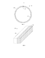
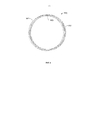
На Фиг. 1 показано уплотнительное кольцо в соответствии с предпочтительным вариантом реализации настоящего изобретения.In FIG. 1 shows an o-ring in accordance with a preferred embodiment of the present invention.
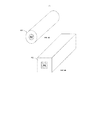
На Фиг. 2 представлено схематическое изображение, иллюстрирующее экструдированный термопластический стержень, содержащий два полимерных слоя в соответствии с вариантами реализации настоящего изобретения.In FIG. 2 is a schematic view illustrating an extruded thermoplastic rod containing two polymer layers in accordance with embodiments of the present invention.
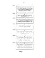
На Фиг. 3 представлена блок-схема, иллюстрирующая этапы способа получения уплотнительного кольца в соответствии с предпочтительными вариантами реализации настоящего изобретения.In FIG. 3 is a flowchart illustrating the steps of a method for producing an o-ring in accordance with preferred embodiments of the present invention.
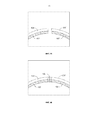
На Фиг. 4А и 4В представлены схематические диаграммы, иллюстрирующие способ сварки концов термопластического стержня согнутого в круглую форму в соответствии с вариантами реализации настоящего изобретения.In FIG. 4A and 4B are schematic diagrams illustrating a method for welding the ends of a thermoplastic rod bent into a circular shape in accordance with embodiments of the present invention.
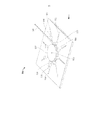
На Фиг. 5 представлена иллюстрация устройства формования, известного из уровня техники, которое можно применять для получения уплотнительных колец в соответствии с предпочтительными вариантами реализации настоящего изобретения.In FIG. 5 is an illustration of a molding apparatus known in the art that can be used to produce o-rings in accordance with preferred embodiments of the present invention.
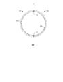
На Фиг. 6 показано уплотнительное кольцо в соответствии с предпочтительным вариантом реализации настоящего изобретения, в котором два термопластических стержня соединены с получением уплотнительного кольца с двумя сварными швами.In FIG. 6 shows an o-ring in accordance with a preferred embodiment of the present invention, in which two thermoplastic rods are connected to form an o-ring with two welds.
На Фиг. 7 показано уплотнительное кольцо в соответствии с другим предпочтительным вариантом реализации настоящего изобретения.In FIG. 7 shows an o-ring in accordance with another preferred embodiment of the present invention.
На Фиг. 8А показан сегмент уплотнительного кольца в соответствии с другим вариантом реализации настоящего изобретения, в котором уплотнительное кольцо имеет прямоугольное сечение.In FIG. 8A shows a segment of an o-ring in accordance with another embodiment of the present invention, in which the o-ring has a rectangular cross-section.
На Фиг. 8В показан сегмент уплотнительного кольца в соответствии с другим вариантом реализации настоящего изобретения, в котором уплотнительное кольцо имеет полигональное сечение с 4 сторонами.In FIG. 8B shows a segment of an o-ring in accordance with another embodiment of the present invention, in which the o-ring has a polygonal section with 4 sides.
Не предполагается, что прилагаемые к настоящему документу чертежи выполнены в масштабе. На чертежах каждый идентичный или почти идентичный компонент, который проиллюстрирован на различных фигурах, обозначен тем же числом. Для наглядности не каждый компонент может быть помечен на каждом чертеже.It is not intended that the accompanying drawings be drawn to scale. In the drawings, each identical or nearly identical component that is illustrated in various figures is denoted by the same number. For clarity, not every component can be marked on each drawing.
ОПИСАНИЕ ГРАФИЧЕСКИХ МАТЕРИАЛОВDESCRIPTION OF GRAPHIC MATERIALS
Несмотря на то, что наполненные полимерные материалы, такие как наполненные политетрафторэтиленом материалы, часто имеют весьма желательные характеристики, их может быть трудно применять в обычных способах тепловой сварки. В частности, свариваемый участок наполненного полимера, такого как наполненного политетрафторэтиленом полимера, часто обладает сниженным удлинением при разрыве по сравнению с ненаполненным полимером. Это делает такие наполненные политетрафторэтиленом материалы менее подходящими для такого применения, как уплотнительные кольца большого диаметра, опорные кольца или другие уплотнительные устройства, где желательное удлинение при разрыве составляет не менее 3%.Although filled polymeric materials, such as polytetrafluoroethylene-filled materials, often have highly desirable characteristics, they can be difficult to use in conventional heat welding methods. In particular, a weldable portion of a filled polymer, such as a polytetrafluoroethylene-filled polymer, often has a reduced elongation at break compared to an unfilled polymer. This makes such polytetrafluoroethylene-filled materials less suitable for applications such as large diameter o-rings, abutment rings or other sealing devices where the desired elongation at break is at least 3%.
Заявители обнаружили, что применение совместно экструдированного опорного слоя ненаполненного полимера неожиданно повышает прочность сварного шва в целом, в том числе сварного шва наполненного политетрафторэтиленом полимерного слоя. Функциональный заполненный политетрафторэтиленом слой может быть ориентирован по направлению к внутренней части уплотнения (по внутреннему периметру к отверстию) или в направлении наружу (по внешнему периметру) в зависимости от того, где для конкретного применения как уплотнитель необходим функциональный политетрафторэтиленовый наполнитель. Во многих типичных применениях наполненный политетрафторэтиленом слой предпочтительно будет ориентирован на внутренней части уплотнения, как показано ниже на Фиг. 1.Applicants have discovered that the use of a co-extruded backing layer of unfilled polymer unexpectedly increases the strength of the weld as a whole, including the weld of a polymer layer filled with polytetrafluoroethylene. A functional PTFE-filled layer can be oriented towards the inside of the seal (along the inner perimeter to the hole) or outward (along the outer perimeter) depending on where a functional PTFE filler is needed for a particular application. In many typical applications, the polytetrafluoroethylene-filled layer will preferably be oriented towards the inside of the seal, as shown below in FIG. one.
Как показано на Фигурах 1 и 2, уплотнительное кольцо 100 может быть образовано из термопластического стержня 200. Предпочтительно термопластический стержень представляет собой экструдированный термопластический стержень, например, такой как стержень, экструдированный из расплава. Кроме того, стержень 200 может представлять собой прессованный стержень. Термопластический стержень 200 предпочтительно содержит по меньшей мере два совместно экструдированных термопластических полимера, при этом два полимера образуют первый продольный слой 102 и второй продольный слой 104, соединенные вместе сварным швом 106. В предпочтительных вариантах реализации настоящего изобретения по меньшей мере один слой содержит соединение, наполненное политетрафторэтиленом, такое как полиэфирэфиркетон, наполненный политетрафторэтиленом. Как обсуждалось выше, может быть очень трудно сваривать соединения, наполненные политетрафторэтиленом, такие как полиэфирэфиркетон, наполненный политетрафторэтиленом. Типичный шов из такого материала имеет удлинение при разрыве, составляющее менее 3% от значения, желаемого для многих применений уплотнительных колец. Заявители обнаружили, что путем совместной экструзии наполненного политетрафторэтиленом полимерного слоя с другим ненаполненным полимерным слоем, имеющим высокий предел прочности на разрыв сварного шва или удлинение при разрыве, можно улучшить прочность сварного шва в целом, в том числе сварного шва наполненного политетрафторэтиленом полимера.As shown in Figures 1 and 2, the o-
На Фиг. 3 представлена блок-схема, иллюстрирующая этапы способа получения уплотнительного кольца в соответствии с предпочтительными вариантами реализации настоящего изобретения. Предпочтительный способ формования уплотнительного кольца включает на этапе 301 образование термопластического стержня посредством совместной экструзии функционального полимера, такого как наполненного политетрафторэтиленом (ПТФЭ) полимера и опорного полимера таким образом, что образованный термопластический стержень содержит по меньшей мере первый слой функционального полимера и второй слой ненаполненного полимера. Такой двухслойный экструдированный стержень схематически показан на Фиг. 2. После того как экструдированный стержень отрезают до требуемой длины (этап 302), стержень нагревают до температуры выше температуры перехода обоих полимерных слоев на этапе 303. На этапе 304 стержень изгибают в круглую форму. После того как стержень был изогнут с образованием кольца, первый и второй концы стержня нагревают до температуры выше температуры плавления обоих слоев на этапе 305. Расплавленные концы затем спрессовывают вместе с образованием сварного кольца на этапе 306. Предпочтительно концы соединены таким образом, что концы наполненного политетрафторэтиленом слоя соединены друг с другом и концы ненаполненного полимерного слоя соединены друг с другом; другими словами, так, чтобы наполненный политетрафторэтиленом полимер был приварен к наполненному политетрафторэтиленом полимеру, а ненаполненный полимер был приварен к ненаполненному полимеру. Наконец, на этапе 307 сваренное кольцо прокаливают для усиления сварного шва и соединения между совместно экструдированными слоями.In FIG. 3 is a flowchart illustrating the steps of a method for producing an o-ring in accordance with preferred embodiments of the present invention. A preferred method for forming an o-ring includes, at
Термопластический стержень может быть любой желаемой формы. Например, стержень может быть выполнен в виде прямого стержня, имеющего прямоугольное поперечное сечение и два продольных слоя приблизительно равных размеров, как показано на Фиг. 2.The thermoplastic rod may be of any desired shape. For example, the rod may be made in the form of a straight rod having a rectangular cross section and two longitudinal layers of approximately equal sizes, as shown in FIG. 2.
Кроме того, стержень может иметь круглое поперечное сечение или многоугольное поперечное сечение. В качестве примера многоугольного поперечного сечения, многоугольник может иметь четыре или более сторон. В качестве альтернативы нагрева и гибки экструдированный стержень может быть экструдирован в виде дуги, а концы дуги соединены для получения уплотнительного устройства. В другом альтернативном варианте реализации настоящего изобретения дуги можно вырезать из листов материала, например, экструдированных листов или прессованных формованных листов и концы дуг соединить.In addition, the rod may have a circular cross section or a polygonal cross section. As an example of a polygonal cross section, a polygon can have four or more sides. As an alternative to heating and bending, the extruded rod can be extruded in the form of an arc, and the ends of the arc are connected to form a sealing device. In another alternative embodiment of the present invention, the arcs can be cut from sheets of material, for example, extruded sheets or extruded molded sheets, and the ends of the arcs are joined.
Термопластический стержень может быть выполнен из двух или более слоев термопластического материала, таких как конструкционный полимер или высокоэффективной термопластический полимер. В предпочтительных вариантах реализации настоящего изобретения по меньшей мере один слой (также называемый в настоящем документе функциональным слоем) образован из термопластического материала, имеющего желаемую характеристику, но имеющего нежелательные для свариваемого материала физические характеристики. Например, термопластический материал, имеющий желаемую характеристику, может представлять собой композитный материал, образованный из матрицы термопластического материала и наполнителя. В конкретном примере наполнитель представляет собой твердый смазочный материал. В другом примере наполнитель содержит фторполимер. В другом примере наполнитель содержит комбинацию твердого смазывающего материала и фторполимера. В варианте реализации настоящего изобретения композиционный материал содержит поликетоновую матрицу, например полиэфирэфиркетон, с политетрафторэтиленом в качестве наполнителя. Как описано ниже, другие твердые смазочные материалы также можно применять в качестве наполнителей.The thermoplastic rod may be made of two or more layers of thermoplastic material, such as a structural polymer or a highly efficient thermoplastic polymer. In preferred embodiments of the present invention, at least one layer (also referred to herein as a functional layer) is formed of a thermoplastic material having a desired characteristic but having physical characteristics undesirable for the material being welded. For example, a thermoplastic material having the desired characteristic may be a composite material formed from a matrix of thermoplastic material and a filler. In a specific example, the filler is a solid lubricant. In another example, the filler comprises a fluoropolymer. In another example, the filler comprises a combination of a solid lubricant and a fluoropolymer. In an embodiment of the present invention, the composite material comprises a polyketone matrix, for example polyetheretherketone, with polytetrafluoroethylene as a filler. As described below, other solid lubricants can also be used as fillers.
Хотя большая часть обсуждения из настоящего документа направлена на наполненные политетрафторэтиленом полимеры, варианты реализации настоящего изобретения также можно применять с другими различными типами наполненных полимеров, которые обладают пониженным пределом прочности на разрыв у сварного шва или удлинения сварного шва при разрыве. В предпочтительных вариантах реализации настоящего изобретения можно применять наполнители, отличные от политетрафторэтилена в соответствии с настоящим изобретением. Например, применяемый наполнитель может содержать другой твердый смазочный материал, керамический или минеральный наполнитель, полимерный наполнитель, волоконный наполнитель, наполнитель в виде частиц металла или соли или любую их комбинацию. Примеры твердых смазочных материалов, за исключением политетрафторэтилена, которые можно применять, включают дисульфид молибдена, дисульфид вольфрама, графит, графен, вспененный графит, нитрид бора, тальк, фторид кальция, фторид церия или любую их комбинацию. Примерный керамический или минеральный наполнитель может включать окись алюминия, окись кремния, диоксид титана, фторид кальция, нитрид бора, слюду, волластонит, карбид кремния, нитрид кремния, диоксид циркония, сажу, пигменты или любую их комбинацию. Примерный полимерный наполнитель может включать полиимид, жидкокристаллические полимеры, такой как полиэфир Ekonol®, полибензимидазол, политетрафторэтилен, любой из термопластических полимеров, перечисленных выше, или любую их комбинацию. Примерный волоконный наполнитель может включать нейлоновые волокна, стекловолокно, углеродные волокна, полиакрилонитрильные волокна, полиарамидные волокна, волокна из политетрафторэтилена, базальтовые волокна, графитовые волокна, керамические волокна или любую их комбинацию. Примерный металлический наполнитель может включать бронзу, медь, нержавеющую сталь или любую их комбинацию. Примерный солевой наполнитель может включать сульфат, сульфид, фосфат или любую их комбинацию.Although most of the discussion in this document is directed to polytetrafluoroethylene-filled polymers, embodiments of the present invention can also be used with other various types of filled polymers that have a reduced tensile strength at the weld or elongation of the weld at break. In preferred embodiments of the present invention, fillers other than polytetrafluoroethylene in accordance with the present invention can be used. For example, the filler used may comprise another solid lubricant, a ceramic or mineral filler, a polymer filler, a fiber filler, a metal or salt particle filler, or any combination thereof. Examples of solid lubricants, with the exception of polytetrafluoroethylene, which can be used include molybdenum disulfide, tungsten disulfide, graphite, graphene, foamed graphite, boron nitride, talc, calcium fluoride, cerium fluoride, or any combination thereof. An exemplary ceramic or mineral filler may include alumina, silica, titanium dioxide, calcium fluoride, boron nitride, mica, wollastonite, silicon carbide, silicon nitride, zirconia, carbon black, pigments, or any combination thereof. An exemplary polymeric filler may include polyimide, liquid crystal polymers such as Ekonol® polyester, polybenzimidazole, polytetrafluoroethylene, any of the thermoplastic polymers listed above, or any combination thereof. An exemplary fiber filler may include nylon fibers, fiberglass, carbon fibers, polyacrylonitrile fibers, polyaramide fibers, polytetrafluoroethylene fibers, basalt fibers, graphite fibers, ceramic fibers, or any combination thereof. An exemplary metal filler may include bronze, copper, stainless steel, or any combination thereof. An exemplary salt filler may include sulfate, sulfide, phosphate, or any combination thereof.
В некоторых вариантах реализации настоящего изобретения в качестве матрицы термопластического материала (наполненный материал) могут служить другие виды термопластических материалов, в том числе полимеры, такие как поликетон, полиарамид, термопластический полиимид, полиэфиримид, полифениленсульфид, полиэфирсульфон, полисульфон, полифениленсульфон, полиамидоимид, полиэтилен сверхвысокой молекулярной массы, термопластический фторполимер, полиамид, полибензимидазол, жидкокристаллический полимер или любая их комбинация. В примере термопластический материал включает поликетон, полиарамид, полиимид, полиэфиримид, полиамидоимид, полифениленсульфид, полифениленсульфон, фторполимер, полибензимидазол, их производные или их комбинации. В конкретном примере термопластический материал включает полимер, такой как поликетон, термопластический полиимид, полиэфиримид, полифениленсульфид, полиэфирсульфон, полисульфон, полиамидоимид, их производное или их комбинации. В другом примере термопластический материал включает поликетон, в том числе полиарилэфирэфиркетон, как обсуждалось выше, полиэфиркетон, полиэфиркетон кетон, полиэфиркетон эфиркетон кетон, их производное или их комбинации. Примерный термопластический материал может также включать ароматические полиэфирные полимеры, такие как те, которые доступны под торговыми названиями XYDAR® (Amoco), VECTRA® (Hoechst Celanese), SUMIKOSUPER™ или EKONOL™ (Sumitomo Chemical), DuPont HX™ или DuPont ZENITE™ (E.I. DuPont de Nemours), RODRUN™ (Unitika), GRANLAR™ (Grandmont) или любую их комбинацию. В качестве дополнительного примера термопластический полимер может быть полиэтиленом сверхвысокой молекулярной массы. В этом процессе можно применять полиэтилен сверхвысокой молекулярной массы, несмотря на то, что его температура перехода составляет примерно -160°С.In some embodiments of the present invention, other types of thermoplastic materials can serve as a matrix of thermoplastic material (filled material), including polymers such as polyketone, polyaramide, thermoplastic polyimide, polyetherimide, polyphenylene sulfide, polyethersulfone, polysulfone, polyphenylene sulfone, polyamidoimide, polyethylene molecular weight, thermoplastic fluoropolymer, polyamide, polybenzimidazole, liquid crystal polymer, or any combination thereof. In an example, the thermoplastic material includes polyketone, polyaramide, polyimide, polyetherimide, polyamidoimide, polyphenylene sulfide, polyphenylene sulfone, fluoropolymer, polybenzimidazole, derivatives thereof, or combinations thereof. In a specific example, the thermoplastic material includes a polymer, such as polyketone, thermoplastic polyimide, polyetherimide, polyphenylene sulfide, polyethersulfone, polysulfone, polyamidoimide, a derivative thereof, or combinations thereof. In another example, the thermoplastic material includes polyketone, including polyarylether ether ketone, as discussed above, polyether ketone, polyether ketone ketone, polyether ketone ether ketone, a derivative thereof, or combinations thereof. Exemplary thermoplastic material may also include aromatic polyester polymers such as those available under the trade names XYDAR® (Amoco), VECTRA® (Hoechst Celanese), SUMIKOSUPER ™ or EKONOL ™ (Sumitomo Chemical), DuPont HX ™ or DuPont ZENITE ™ ( EI DuPont de Nemours), RODRUN ™ (Unitika), GRANLAR ™ (Grandmont), or any combination thereof. As a further example, the thermoplastic polymer may be ultra high molecular weight polyethylene. In this process, ultra-high molecular weight polyethylene can be used, despite the fact that its transition temperature is about -160 ° C.
В других вариантах реализации настоящего изобретения термопластический материал может включать термопластические фторполимеры, такие как фторированный этилен-пропилен (FEP), политетрафторэтилен (ПТФЭ), поливинилиденфторид (ПВДФ), перфторалкокси (ПФА), терполимер тетрафторэтилена, гексафторпропилена и винилиденфторида (THV), полихлортрифторэтилен (ПХТФЭ), сополимер этилена и тетрафторэтилена (ETFE), сополимер этилена и хлортрифторэтилена (ECTFE) или любую их комбинацию. В некоторых случаях ненаполненный полимер, например, такой как политетрафторэтилен (отдельно), имеющий желаемые характеристики, также можно применять в соответствии с вариантами реализации настоящего изобретения.In other embodiments of the present invention, the thermoplastic material may include thermoplastic fluoropolymers such as fluorinated ethylene propylene (FEP), polytetrafluoroethylene (PTFE), polyvinylidene fluoride (PVDF), perfluoroalkoxy (PFA), tetrafluoroethylene, hexafluorofluorofluoride (vinylthene) vinyl terphenyl (vinyl) PCTFE), ethylene-tetrafluoroethylene copolymer (ETFE), ethylene-chlorotrifluoroethylene copolymer (ECTFE), or any combination thereof. In some cases, an unfilled polymer, for example, such as polytetrafluoroethylene (separately), having the desired characteristics, can also be used in accordance with embodiments of the present invention.
Применяя конкретный пример, описанный выше, уплотнительное кольцо, образованное из наполненного политетрафторэтиленом полиэфирэфиркетона, имеет очень желательные характеристики, в том числе желательные характеристики износа и низкий коэффициент трения. К сожалению, уплотнительное кольцо, образованное с помощью сварки наполненного политетрафторэтиленом полиэфирэфиркетонового стержня, как описано выше, также обладает нежелательными физическими характеристиками. В частности, сваренный наполненный политетрафторэтиленом полиэфирэфиркетон обладает удлинением при разрыве менее 3%, что нежелательно для уплотнительного кольца большого диаметра. Варианты реализации настоящего изобретения обеспечивают законченное уплотнительное кольцо, в котором можно сохранить желательные свойства наполненного политетрафторэтиленом полиэфирэфиркетона, в то время как нежелательную характеристику, а именно удлинение при разрыве, можно улучшить. Заявители обнаружили, что сочетание слоя наполненного политетрафторэтиленом полиэфирэфиркетона с совместно экструдированным "опорным" слоем полимера, имеющего более желательные характеристики, такие как удлинение при разрыве или предел прочности на разрыв (при растяжении), неожиданно улучшает прочность сварного шва в целом, в том числе сварного шва слоя полимера, наполненного политетрафторэтиленом.Using the specific example described above, an o-ring formed from polytetrafluoroethylene-filled polyether etherketone has very desirable characteristics, including desirable wear characteristics and a low friction coefficient. Unfortunately, an o-ring formed by welding a polytetrafluoroethylene-filled polyether ether ketone rod as described above also has undesirable physical characteristics. In particular, the welded polyetheretherketone filled with polytetrafluoroethylene has an elongation at break of less than 3%, which is undesirable for a large diameter o-ring. Embodiments of the present invention provide a complete o-ring in which the desired properties of the polytetrafluoroethylene-filled polyetheretherketone filled can be maintained, while an undesirable characteristic, namely elongation at break, can be improved. Applicants have discovered that the combination of a polytetrafluoroethylene-filled polyether ether ketone layer with a co-extruded “backing” polymer layer having more desirable characteristics, such as elongation at break or tensile strength (tensile), unexpectedly improves the overall weld strength, including weld seam of a polymer layer filled with polytetrafluoroethylene.
"Опорный" полимер в соответствии с настоящим изобретением может представлять собой любой термопластический материал, имеющий желательные физические характеристики, такие как удлинение при разрыве или предел прочности на разрыв, достаточные для компенсации недостатков (нежелательных характеристик) функционального полимерного слоя. Любой из термопластических материалов, описанных выше, пригодный для применения в качестве матрицы термопластического материала (заполненного материала), также можно применять в качестве опорного полимера. В некоторых предпочтительных вариантах реализации настоящего изобретения материал, применяемый для опорного полимера, представляет собой тот же материал, который применяют в качестве матрицы термопластического материала (заполненный материал) в функциональном слое. Например, в предпочтительном варианте реализации настоящего изобретения наполненный политетрафторэтиленом полиэфирэфиркетон можно применять для функционального слоя, в то время как незаполненный полиэфирэфиркетон можно совместно экструдировать в качестве опорного слоя. Предпочтительно опорный полимер и термопластический материал матрицы будут иметь одинаковые температуру перехода и температуру плавления.A “support” polymer according to the present invention can be any thermoplastic material having the desired physical characteristics, such as elongation at break or tensile strength, sufficient to compensate for the drawbacks (undesirable characteristics) of the functional polymer layer. Any of the thermoplastic materials described above, suitable for use as a matrix of thermoplastic material (filled material), can also be used as a reference polymer. In some preferred embodiments of the present invention, the material used for the support polymer is the same material that is used as the matrix of the thermoplastic material (filled material) in the functional layer. For example, in a preferred embodiment of the present invention, polytetrafluoroethylene-filled polyether ether ketone can be used for the functional layer, while unfilled polyether ether ketone can be coextruded as a backing layer. Preferably, the support polymer and the thermoplastic matrix material will have the same transition temperature and melting point.
Предпочтительно термопластический стержень образован путем совместной экструзии двух или более слоев термопластического материала. Совместная экструзия является хорошо известным в предыдущем уровне техники способом, в котором два или более полимера экструдированы и соединены вместе в непрерывный профиль. В предпочтительном варианте реализации настоящего изобретения два или более слоя экструдированы из расплава. В некоторых вариантах реализации настоящего изобретения, в качестве альтернативы нагрева и гибки, слои могут быть экструдированы в форме дуги с помощью регулирования относительных скоростей и объема экструдируемых материалов. Предпочтительно два слоя поддерживают равномерную толщину в процессе экструзии. В варианте реализации настоящего изобретения, показанном на фиг. 2, эти два слоя имеют, по существу, одинаковую толщину, хотя можно применять различные толщины слоев в зависимости от механических свойств слоев и желаемой функциональной характеристики готового уплотнительного кольца. В некоторых вариантах реализации настоящего изобретения термопластический стержень можно получать с помощью других подходящих известных процессов, таких как компрессионное формование, хотя, если применяют другие способы, могут быть необходимы дополнительные этапы нагревания или отжига, описанные ниже, для формирования требуемой степени прочности связи между слоями стержня.Preferably, the thermoplastic core is formed by co-extrusion of two or more layers of thermoplastic material. Co-extrusion is a method well known in the prior art in which two or more polymers are extruded and bonded together in a continuous profile. In a preferred embodiment of the present invention, two or more layers are extruded from the melt. In some embodiments of the present invention, as an alternative to heating and bending, the layers can be extruded in the form of an arc by controlling the relative speeds and volume of the extrudable materials. Preferably, the two layers maintain uniform thickness during the extrusion process. In the embodiment of the present invention shown in FIG. 2, these two layers have substantially the same thickness, although different layer thicknesses can be applied depending on the mechanical properties of the layers and the desired functional characteristics of the finished o-ring. In some embodiments of the present invention, a thermoplastic rod can be obtained using other suitable known processes, such as compression molding, although if other methods are used, additional heating or annealing steps, described below, may be necessary to form the required degree of bond strength between the layers of the rod .
В качестве примера толщина поперечного сечения в экструдированном стержне, которая становится радиальной толщиной после выгибания, может быть меньше, чем 1/5 или 20% от наружного диаметра окружности, определенной дугой изогнутого экструдированного стержня. Например, наружный диаметр окружности, включая дугу, определенную изогнутым стержнем, может быть по крайней мере в 5 раз больше радиальной толщины стержня, например по меньшей мере в 10 раз больше радиальной толщины или даже по меньшей мере в 20 раз больше радиальной толщины. В конкретном варианте реализации настоящего изобретения радиальная толщина составляет по меньшей мере 1 дюйм, например по меньшей мере 2 дюйма.As an example, the thickness of the cross section in the extruded rod, which becomes the radial thickness after bending, may be less than 1/5 or 20% of the outer diameter of the circle defined by the arc of the curved extruded rod. For example, the outer diameter of a circle, including an arc defined by a curved rod, can be at least 5 times larger than the radial thickness of the rod, for example at least 10 times larger than the radial thickness or even at least 20 times larger than the radial thickness. In a particular embodiment, the radial thickness is at least 1 inch, for example at least 2 inches.
Поперечное сечение экструдированного стержня может быть в форме круга или в форме многоугольника. В частности, многоугольник может иметь по меньшей мере три стороны, например по меньшей мере четыре стороны. В качестве примера многоугольник представляет в поперечном сечении четырехугольник, такой как прямоугольник или квадрат. В конкретном примере площадь поперечного сечения стержня составляет по меньшей мере 1 кв. дюйм, например по меньшей мере 2 кв. дюйма, или даже по меньшей мере 3 кв. дюйма. Кроме того, в некоторых вариантах реализации настоящего изобретения область поперечного сечения может составлять не больше чем 50 кв. дюймов.The cross section of the extruded rod may be in the form of a circle or in the form of a polygon. In particular, a polygon can have at least three sides, for example at least four sides. By way of example, a polygon is in cross section a quadrangle, such as a rectangle or square. In a specific example, the cross-sectional area of the rod is at least 1 square. inch, for example at least 2 square meters. inches, or even at least 3 square meters. inches. In addition, in some embodiments of the present invention, the cross-sectional area may be no more than 50 square meters. inches.
Поскольку процесс экструзии обеспечивает непрерывную длину материала, экструдированный стержень должен быть отрезан до необходимой длины. Фактическая длина стержня будет зависеть от желаемого диаметра уплотнительного кольца, которое будет образовано после гибки и сварки стержня. В предпочтительных вариантах реализации настоящего изобретения уплотнительные кольца, как описано в настоящем документе, будут иметь окружность по меньшей мере 0,62 метра, например по меньшей мере 1,0 метра, по меньшей мере 1,5 метра, по меньшей мере 2,0 метра, по меньшей мере 4,1 метра, по меньшей мере 4,5 метра или даже по меньшей мере 4,8 метра.Since the extrusion process provides a continuous length of material, the extruded rod must be cut to the required length. The actual length of the rod will depend on the desired diameter of the o-ring, which will be formed after bending and welding the rod. In preferred embodiments of the present invention, the o-rings as described herein will have a circumference of at least 0.62 meters, for example at least 1.0 meters, at least 1.5 meters, at least 2.0 meters at least 4.1 meters, at least 4.5 meters, or even at least 4.8 meters.
После того, как термопластический стержень требуемого состава и длины была образован, стержень нужно сформировать в уплотнительное кольцо. Это может быть достигнуто путем сначала нагрева стержня до температуры выше температуры стеклования всех полимерных слоев таким образом, что стержень может быть легко изогнут в круглую форму. Например, экструдированный полиэфирэфиркетон имеет температуру стеклования примерно 143°С и температуру плавления приблизительно 343°С. Политетрафторэтиленовый наполнитель имеет сравнимые температуры стеклования и плавления, примерно 130°С (температура стеклования) и 327°С (температура плавления). Композит из полиэфирэфиркетона и политетрафторэтилена легче сформировать в желаемую форму при температуре выше температуры перехода обоих компонентов и ниже фактической точки плавления любого из этих материалов. В целом гибкость экструдированного стержня будет увеличиваться при увеличении температуры. В предпочтительном варианте реализации настоящего изобретения термопластический стержень (в том числе наполненный политетрафторэтиленом полиэфирэфиркетоновый слой и опорный слой из ненаполненного полиэфирэфиркетона) нагревают приблизительно до 310°С для обеспечения максимальной гибкости. Квалифицированному специалисту в данной области техники будет очевидно, что на этапе гибки в целом нежелательно нагревать стержень выше температуры плавления любого из материалов.After the thermoplastic rod of the required composition and length has been formed, the rod must be formed into a sealing ring. This can be achieved by first heating the rod to a temperature above the glass transition temperature of all polymer layers so that the rod can be easily bent into a round shape. For example, extruded polyether ether ketone has a glass transition temperature of about 143 ° C. and a melting point of about 343 ° C. The polytetrafluoroethylene filler has comparable glass transition and melting temperatures of about 130 ° C (glass transition temperature) and 327 ° C (melting temperature). A composite of polyetheretherketone and polytetrafluoroethylene is easier to form into the desired shape at a temperature above the transition temperature of both components and below the actual melting point of any of these materials. In general, the flexibility of the extruded core will increase with increasing temperature. In a preferred embodiment of the present invention, the thermoplastic core (including the polytetrafluoroethylene-filled polyether ether ketone layer and the unfilled polyether ether ketone backing layer) is heated to approximately 310 ° C. for maximum flexibility. It will be apparent to those skilled in the art that at the bending step it is generally undesirable to heat the rod above the melting point of any of the materials.
В предпочтительных вариантах реализации настоящего изобретения термопластический опорный материал и матрица функционального слоя включают термопластический материал, имеющий температуру стеклования более 100°С, например, по меньшей мере 125°С или даже по меньшей мере 145°С. Одним из исключений является полиэтилен сверхвысокой молекулярной массы, который имеет температуру стеклования, составляющую -160°С, и температуру плавления 135°С. Тепловой индекс термопластического материала может находиться в диапазоне от 0,60 до 0,999. Тепловой индекс представляет собой отношение температуры, до которой материал нагревают, деленной на температуру плавления. В другом примере индекс тепла может находиться в диапазоне от 0,70 до 0,999, такой как в диапазоне от 0,8 до 0,999, или даже в диапазоне от 0,9 до 0,99.In preferred embodiments of the present invention, the thermoplastic support material and the functional layer matrix include a thermoplastic material having a glass transition temperature of more than 100 ° C, for example at least 125 ° C or even at least 145 ° C. One exception is ultra-high molecular weight polyethylene, which has a glass transition temperature of -160 ° C and a melting point of 135 ° C. The thermal index of a thermoplastic material can range from 0.60 to 0.999. The thermal index is the ratio of the temperature to which the material is heated divided by the melting point. In another example, the heat index may be in the range of 0.70 to 0.999, such as in the range of 0.8 to 0.999, or even in the range of 0.9 to 0.99.
После того, как термопластический стержень из функционального и опорного материала был нагрет до точки, где он становится достаточно гибким, ему можно придать круглую форму, например, с помощью формовочной машины, как описано в патенте США №2010/0116422. На Фиг. 5 показана подходящая формовочная машина 500 для гибки термопластического стержня в круглую форму в соответствии с вариантами реализации настоящего изобретения. Формовочная машина 500 содержит круговую форму 502, которая поворачивается вокруг оси 503. Вокруг периметра круговой формы 502 предусмотрен паз 504 для зацепления изделия 506. В частности, изделие 506 может быть зажато в паз зажимом 508. Кроме того, формовочная машина 500 может содержать набор роликов 510, распределенных по периметру круговой формы 502. Ось ролика 510 может быть прикреплена к каткам, который движутся по дорожкам 512 или к направляющим стержням. Соответственно, ролики 510 могут контактировать с круговой формой 502 или могут быть высвобождены и отодвинуты от круговой формы 502.After the thermoplastic core of the functional and supporting material has been heated to the point where it becomes sufficiently flexible, it can be shaped into a round shape, for example, using a molding machine, as described in US patent No. 2010/0116422. In FIG. 5 shows a
При применении зажим 508 закрепляет изделие 506 к круговой форме 502. Круговая форма 502 вращается и зажим 508 вращается вместе с круговой формой 502, протягивая изделие 506 по периметру круговой формы 502 и в паз 504. Поскольку зажим 508 движется мимо ролика 510, ролик 510 контактирует с изделием 506 и круговой формой 502, применяя радиальное усилие к изделию 506. Соответственно, изделие 506 формуется в виде дугообразной конструкции, которую можно применять для получения уплотнительного кольца. В другом примере круговую форму 502 можно нагреть для передачи тепла изделию 506. В другом примере гибку можно выполнять в нагретой среде, такой как печь.In use, the
После того, как сформирована надлежащая форма, изогнутый экструдированный стержень можно охладить. Например, изогнутый экструдированный стержень можно охлаждать до температуры ниже температуры стеклования. В частности, изогнутый экструдированный стержень можно оставлять охлаждаться до температуры, близкой к комнатной температуре. В качестве примера изогнутый стержень охлаждают с помощью принудительной конвекции. Впоследствии изогнутый стержень можно вынимать из круговой формы.After the proper shape is formed, the curved extruded rod can be cooled. For example, a curved extruded rod can be cooled to a temperature below the glass transition temperature. In particular, a curved extruded rod may be allowed to cool to a temperature close to room temperature. As an example, a curved rod is cooled by forced convection. Subsequently, the curved rod can be removed from a circular shape.
В процессе подготовки концов стержня к соединению стержень можно необязательно высушить. Например, стержень можно нагреть до температуры, превышающей 100°С. В конкретном примере стержень можно нагреть до температуры по меньшей мере около 110°С, например по меньшей мере 130°С или даже по меньшей мере примерно 145°С в течение не менее одного часа, например по меньшей мере два часа или даже три часа или больше. Кроме того, стержень можно удалять из формы в горячем состоянии, но ниже его температуры стеклования. В то время как стержень находится в горячем состоянии, концы можно соединять, например, с помощью описанного ниже способа сварки расплавлением, что служит для поддержания стержня в сухом состоянии без дополнительного этапа сушки.In the process of preparing the ends of the rod for connection, the rod may optionally be dried. For example, the rod can be heated to a temperature in excess of 100 ° C. In a specific example, the rod can be heated to a temperature of at least about 110 ° C, for example at least 130 ° C or even at least about 145 ° C for at least one hour, for example at least two hours or even three hours, or more. In addition, the core can be removed from the mold when it is hot, but below its glass transition temperature. While the rod is hot, the ends can be joined, for example, using the fusion welding method described below, which serves to keep the rod dry without an additional drying step.
После того, как стержень изогнули в требуемую круговую форму, концы экструдированного стержня можно сваривать сплавлением торцов стержня и их совместным спрессовыванием для образования кольца. В качестве примера концы расплавляют с применением источника тепла. Например, источником тепла может служить контактный источник тепла, при этом оба конца приведены в контакт с источником тепла и расплавляются с помощью кондуктивного теплообмена. В качестве примера контактный источник тепла контакта представляет собой плоскую нагретую пластину. В другом примере источником тепла может служить бесконтактный источник тепла, такой как излучающий источник тепла или конвективный источник тепла. В качестве альтернативы концы можно соединять с помощью способов, таких как радиочастотные способы, в том числе микроволновые способы, индуктивные способы, лазерные способы или любые их комбинации. В конкретном примере концы стержня соединяют с помощью сварки горячим расплавом. Например, сварка горячим расплавом может включать применение источника тепла к концам стержня для того, чтобы расплавить части стержня, ближайшие к месту плавления, сжимая концы вместе. В таком примере концы стержня плавятся без плавления всего стержня.After the rod is bent to the desired circular shape, the ends of the extruded rod can be welded by fusing the ends of the rod and compressing them together to form a ring. By way of example, the ends are melted using a heat source. For example, a contact heat source may serve as a heat source, with both ends brought into contact with a heat source and melted by conductive heat transfer. By way of example, the contact heat source of the contact is a flat heated plate. In another example, the heat source may be a non-contact heat source, such as a radiating heat source or a convective heat source. Alternatively, the ends can be connected using methods such as radio frequency methods, including microwave methods, inductive methods, laser methods, or any combination thereof. In a specific example, the ends of the rod are joined by hot melt welding. For example, hot melt welding may include applying a heat source to the ends of the rod in order to melt the parts of the rod closest to the melting point, compressing the ends together. In this example, the ends of the rod melt without melting the entire rod.
Температура источника тепла будет зависеть от термопластических материалов, из которых состоит стержень. В качестве примера термопластический материал имеет температуру плавления по меньшей мере 250°С. Например, термопластический материал может иметь температуру плавления по меньшей мере 300°С, например по меньшей мере 320°С. В примере выше экструдированный полиэфирэфиркетон имеет температуру плавления около 343°С, в то время как политетрафторэтиленовый наполнитель имеет температуру плавления около 327°С. В предпочтительном варианте реализации настоящего изобретения концы термопластического стержня, имеющего слои полиэфирэфиркетона и наполненного политетрафторэтиленом полиэфирэфиркетона, можно нагревать до температуры выше 343°С, но ниже температуры, при которой любой из этих материалов будет разрушаться. Например, в эксперименте заявители обнаружили, что сваренный полиэфирэфиркетон имеет более высокое удлинение при разрыве, когда концы нагревают до температуры около 420°С. Более низкая температура (примерно 385°С), как представляется, слишком мала, чтобы вызвать необходимую связь, в то время как более высокая температура (около 445°С) может привести к разрушению образца.The temperature of the heat source will depend on the thermoplastic materials that make up the core. By way of example, the thermoplastic material has a melting point of at least 250 ° C. For example, the thermoplastic material may have a melting point of at least 300 ° C, for example at least 320 ° C. In the example above, the extruded polyether ether ketone has a melting point of about 343 ° C, while the polytetrafluoroethylene filler has a melting point of about 327 ° C. In a preferred embodiment of the present invention, the ends of a thermoplastic rod having layers of polyether ether ketone and filled with polytetrafluoroethylene polyether ether ketone can be heated to a temperature above 343 ° C, but below the temperature at which any of these materials will break. For example, in an experiment, applicants found that the cooked polyether ether ketone has a higher elongation at break when the ends are heated to a temperature of about 420 ° C. A lower temperature (about 385 ° C) seems to be too small to cause the necessary connection, while a higher temperature (about 445 ° C) can lead to destruction of the sample.
На Фиг. 4А и 4В показаны концы изогнутого стержня, приближающиеся друг к другу, а затем сжатые вместе. Когда расплавленные концы сжимают вместе, они образуют сварной шов 404, который соединяет два конца стержня. В некоторых предпочтительных вариантах реализации настоящего изобретения уплотнительное кольцо в соответствии с настоящим изобретением может включать более одного сварного шва, например два сварных шва или даже три или более сварных шва. На Фиг. 6 показано уплотнительное кольцо в соответствии с предпочтительным вариантом реализации настоящего изобретения, в котором два термопластических стержня соединены с получением уплотнительного кольца с двумя сварными швами. В случае, когда соединяют вместе несколько стержней, предпочтительно соединять концы стержней так, как описано выше, когда опорный полимер соединяют с опорным полимером, а функциональный полимер - с функциональным полимером.In FIG. 4A and 4B show the ends of a curved rod approaching each other and then compressed together. When the molten ends are compressed together, they form a weld seam 404 that connects the two ends of the rod. In some preferred embodiments of the present invention, the o-ring in accordance with the present invention may include more than one weld, for example two welds, or even three or more welds. In FIG. 6 shows an o-ring in accordance with a preferred embodiment of the present invention, in which two thermoplastic rods are connected to form an o-ring with two welds. In the case where several rods are joined together, it is preferable to connect the ends of the rods as described above, when the support polymer is connected to the support polymer and the functional polymer to the functional polymer.
Кроме того, сварку или соединение дуг или частей можно применять для составления круглых, овальных, многоугольных уплотнений или уплотнений сложной формы.In addition, welding or joining of arcs or parts can be used to form round, oval, polygonal or complex shaped seals.
Например, уплотнение может иметь многоугольную форму, такую как треугольник, квадрат, прямоугольник, пятиугольник, шестиугольник, семиугольник, восьмиугольник или любые их комбинации. Многоугольник может иметь по меньшей мере четыре стороны, например по меньшей мере 6 сторон, по меньшей мере 8 сторон или даже по меньшей мере 10 сторон. В другом примере сложная форма может быть фигурой в форме восьмерки, неправильными многоугольниками или другими сложными формами. В частности, формы могут быть закрытыми. В качестве альтернативы, формы могут быть открытыми, имеющими один или несколько разрывов на своем протяжении.For example, the seal may have a polygonal shape, such as a triangle, square, rectangle, pentagon, hexagon, heptagon, octagon, or any combination thereof. A polygon can have at least four sides, for example at least 6 sides, at least 8 sides, or even at least 10 sides. In another example, the complex shape may be a figure in the shape of a figure of eight, irregular polygons, or other complex shapes. In particular, the forms may be closed. Alternatively, the forms may be open, having one or more gaps along its length.
Приводимый в качестве примера способ сварки также можно применять для сварки дуг из экструдированных или прессованных термопластиков, которые вырезаны из пластины для создания сварного кольца с желаемыми свойствами после отжига. Хотя в настоящем документе применяют сварку для того, чтобы отдельно обозначить способ, в котором нагревают концы стержней и сжимают концы вместе, для соединения концов стержней можно применять и другие способы соединения. Например, другие соединяющие способы могут включать литье под давлением для соединения концов, ультразвуковой способ, способ индукционного нагрева или способы, связанные с излучением, такие как лазерный или микроволновой способы. Соединение между примыкающими друг к другу концами, образованное с помощью любого такого способа, будет упоминаться в настоящем документе как "сварной шов".An example welding method can also be used to weld arcs of extruded or extruded thermoplastics, which are cut from a plate to create a welded ring with the desired properties after annealing. Although welding is used herein to separately indicate the method in which the ends of the rods are heated and the ends are pressed together, other joining methods can be used to connect the ends of the rods. For example, other connecting methods may include injection molding to connect the ends, an ultrasonic method, an induction heating method, or radiation related methods such as laser or microwave methods. A connection between adjacent ends formed by any such method will be referred to herein as a “weld”.
Когда концы экструдированного стержня, содержащего два или более слоя термопластического материала, соединены вместе, концы предпочтительно соединены таким образом, что один конец каждого из слоев присоединяется к другому концу такого же слоя, как показано на Фиг. 4А и 4В. Другими словами, на примере выше, полиэфирэфиркетоновый слой 102 будет приварен к другому концу полиэфирэфиркетонового слоя 102', в то время как концы наполненного политетрафторэтиленом полиэфирэфиркетона 104 и 104' также будут сварены вместе. В целом это позволяет желательному материалу, в этом примере не наполненному полиэфирэфиркетону, механически иметь самый крепкий сварной шов 106.When the ends of an extruded rod containing two or more layers of thermoplastic material are joined together, the ends are preferably connected so that one end of each of the layers joins the other end of the same layer as shown in FIG. 4A and 4B. In other words, in the example above, the polyether
Предпочтительно слоистый стержень изогнут в круглую форму, при этом один слой образует внутренний периметр кольца, а другой полимерный слой образует внешний периметр кольца, как показано на Фиг. 1. В других вариантах реализации настоящего изобретения слоистый стержень можно изогнуть так, что один слой образует одну поверхность полученного кольца, в то время как другой слой образует другую поверхность, как показано на Фиг. 6. Специалистом в данной области техники будет понятно, что желательная окончательная форма кольца будет определена конкретным применением кольца, особенно применением функционального слоя кольца. Во многих случаях будет желательно, чтобы функциональный слой, такой как слой наполненного политетрафторэтиленом полиэфирэфиркетона, был ориентирован по направлению к внутренней стороне кольца (в направлении отверстия), с опорным слоем, ориентированным в направлении внешнего периметра кольца, как показано на Фиг. 1.Preferably, the laminated rod is bent into a circular shape, with one layer forming the inner perimeter of the ring and the other polymer layer forming the outer perimeter of the ring, as shown in FIG. 1. In other embodiments of the present invention, the layered rod can be bent so that one layer forms one surface of the obtained ring, while the other layer forms another surface, as shown in FIG. 6. One skilled in the art will recognize that the desired final ring shape will be determined by the particular use of the ring, especially the use of the functional layer of the ring. In many cases, it will be desirable for a functional layer, such as a layer filled with polytetrafluoroethylene polyetheretherketone, to be oriented toward the inner side of the ring (in the direction of the hole), with a support layer oriented toward the outer perimeter of the ring, as shown in FIG. one.
После того, как концы стержня были соединены с помощью сварки, экструдированный стержень образует сварное кольцо. Желательно сварное кольцо затем подвергнуть отжигу путем нагрева кольца до температуры большей, чем температура стеклования термопластических материалов. При нагревании таким образом сварного кольца, полимерный материал предпочтительно диффундирует через сварной шов, тем самым способствуя переплетению цепей макромолекул в зоне сварного шва и приводит к более высоким значениям растяжения на разрыв.After the ends of the rod were joined by welding, the extruded rod forms a welded ring. Preferably, the welded ring is then annealed by heating the ring to a temperature higher than the glass transition temperature of thermoplastic materials. When the weld ring is heated in this way, the polymer material preferably diffuses through the weld, thereby contributing to the weaving of the chains of macromolecules in the weld zone and leads to higher tensile values.
В частности, температура отжига может быть по меньшей мере в 1,2 раза больше температуры стеклования, по меньшей мере одного полимерного компонента одного или обоих слоев, например по меньшей мере в 1,5 раза больше или даже по меньшей мере в 1,7 раз больше температуры стеклования, при условии, что температура не превышает температуру плавления. В то время как более высокие температуры уменьшают время при температуре отжига, необходимое для достижения оптимальной адгезии, температура должна быть ниже температуры течения для материала слоев, чтобы избежать деформации сварного кольца.In particular, the annealing temperature can be at least 1.2 times the glass transition temperature of at least one polymer component of one or both layers, for example at least 1.5 times higher, or even at least 1.7 times more than the glass transition temperature, provided that the temperature does not exceed the melting point. While higher temperatures reduce the time at the annealing temperature needed to achieve optimal adhesion, the temperature should be lower than the flow temperature for the layer material to avoid deformation of the weld ring.
Сварные кольцо предпочтительно выдерживают при температуре отжига в течение периода времени, достаточного для того, чтобы по меньшей мере один компонент слоя частично диффундировал в смежный слой. Количество времени и температуру на этапе отжига, необходимые для достижения желаемых результатов или максимальной адгезии шва, можно определить путем простой проверки; они будут зависеть от факторов, очевидных для специалистов в данной области техники, таких как толщина каждого слоя и конкретные составы слоев. В целом, более толстые слои и более высокомолекулярные компоненты потребует более длительного времени или более высоких температур.The welded ring is preferably held at annealing temperature for a period of time sufficient for at least one component of the layer to partially diffuse into the adjacent layer. The amount of time and temperature at the annealing stage, necessary to achieve the desired results or maximum adhesion of the seam, can be determined by a simple check; they will depend on factors obvious to those skilled in the art, such as the thickness of each layer and the specific composition of the layers. In general, thicker layers and higher molecular weight components will require a longer time or higher temperatures.
Например, сварное кольцо можно отжигать при температуре выше температуры стеклования экструдированного термопластического материала в течение периода не менее двух часов, такого как по меньшей мере четырех часов или даже по меньшей мере шести часов. В конкретном примере сварное кольцо можно отжигать, например, при температуре выше 100°С, такой как температура выше 120°С, в течение не менее одного часа, например, по меньшей мере двух часов. Температуру можно поднимать до температуры отжига со скоростью в диапазоне от 5°С в час до 15°С в час, такой как от 8°С в час до 12°С в час. После того, как температура отжига будет достигнута, температуру можно поддерживать в течение периода не менее двух часов, такого как по меньшей мере четырех часов, по меньшей мере шести часов или даже восьми часов или более. Затем кольцо можно охлаждать с контролируемой скоростью, такой как со скоростью в диапазоне от 5°С в час до 15°С в час, такой как в диапазоне от 8°С в час до 12°С в час, до температура ниже, чем температура стеклования. Сварному кольцу можно затем дать остыть до комнатной температуры. В качестве примера кольцо можно оставлять в печи, когда печь выключена, до тех пор, пока не будет достигнута комнатная температура.For example, a welded ring can be annealed at temperatures above the glass transition temperature of the extruded thermoplastic material for a period of at least two hours, such as at least four hours or even at least six hours. In a specific example, the welded ring can be annealed, for example, at a temperature above 100 ° C, such as a temperature above 120 ° C, for at least one hour, for example at least two hours. The temperature can be raised to the annealing temperature at a rate in the range from 5 ° C per hour to 15 ° C per hour, such as from 8 ° C per hour to 12 ° C per hour. After the annealing temperature is reached, the temperature can be maintained for a period of at least two hours, such as at least four hours, at least six hours, or even eight hours or more. The ring can then be cooled at a controlled speed, such as at a speed in the range of 5 ° C per hour to 15 ° C per hour, such as in the range of 8 ° C per hour to 12 ° C per hour, to a temperature lower than the temperature glass transition. The welded ring can then be allowed to cool to room temperature. As an example, the ring can be left in the oven when the oven is turned off until room temperature is reached.
Отжиг сваренного кольца служит не только укреплению сварного шва, соединяющего концы термопластического стержня вместе, это также укрепляет связь между совместно экструдированными слоями. Заявители обнаружили, что связь между слоями также значительно улучшает сварные характеристики шва, такие как предел прочности на разрыв и удлинение при разрыве. Заявители полагают, что связь между несущим слоем и функциональным слоем служит для изоляции надрывов или дефектов, возникающих от растяжения сваренного функционального слоя, таким образом предотвращая надрывы слабых мест сварного шва от распространения в большом масштабе. Таким образом, удлинение при разрыве для более слабого функционального слоя может быть улучшено, предпочтительно до значения выше 3%. Например, удлинение при разрыве сварного шва, может быть по меньшей мере 5%, по меньшей мере 10%, по меньшей мере 20% или даже по меньшей мере 30%.Annealing the welded ring not only serves to strengthen the weld connecting the ends of the thermoplastic rod together, it also strengthens the bond between the co-extruded layers. Applicants have found that the bond between the layers also significantly improves the weld characteristics of the weld, such as tensile strength and elongation at break. Applicants believe that the bond between the carrier layer and the functional layer serves to isolate tears or defects arising from the stretching of the welded functional layer, thus preventing large-scale propagation of tears in the weak spots of the weld. Thus, elongation at break for a weaker functional layer can be improved, preferably to a value above 3%. For example, the elongation at break of the weld may be at least 5%, at least 10%, at least 20%, or even at least 30%.
Предпочтительно сварной шов функционального материала и связанного опорного материала также имеет предел прочности на разрыв по меньшей мере 3100 фунт на 1 кв. дюйм (psi), например по меньшей мере 10000 фунт на 1 кв. дюйм или даже по меньшей мере 15000 фунт на 1 кв. дюйм. Кроме того, сварной шов функционального материала и связанного опорного материала предпочтительно имеет модуль упругости при растяжении по меньшей мере 100 тысяч фунтов на 1 кв. дюйм (ksi), например по меньшей мере 750 тысяч фунтов на 1 кв. дюйм или даже по меньшей мере 850 тысяч фунтов на 1 кв. дюйм.Preferably, the weld of the functional material and the associated support material also has a tensile strength of at least 3,100 pounds per square meter. inch (psi), for example at least 10,000 pounds per square meter. an inch or even at least 15,000 pounds per square meter. inch. In addition, the weld of the functional material and the associated support material preferably has a tensile modulus of at least 100 thousand pounds per square meter. inch (ksi), for example at least 750 thousand pounds per square meter. inch or even at least 850 thousand pounds per 1 square. inch.
Кроме того, заявители полагают, что наличие связанного опорного слоя позволяет уплотнительному кольцу функционировать, даже если функциональный полимерный слой поврежден. Это происходит потому, что опорный слой будет продолжать удерживать функциональный слой в надлежащем положении. Таким образом, если надрывы или разрывы возникают в функциональном слое, то при условии, что опорный слой остается неповрежденным, функциональный слой будет оставаться на месте, и уплотнительное кольцо будет продолжать функционировать.In addition, applicants believe that the presence of a bonded support layer allows the o-ring to function, even if the functional polymer layer is damaged. This is because the backing layer will continue to hold the functional layer in a proper position. Thus, if tears or tears occur in the functional layer, provided that the support layer remains intact, the functional layer will remain in place and the o-ring will continue to function.
Таким образом, заявители обнаружили, что связь между слоями является существенным фактором в выборе опорного полимера. В предпочтительных вариантах реализации настоящего изобретения опорный материал и материал матрицы будут одинаковыми. Это обеспечивает максимальную диффузию через линию раздела (как через линию раздела сварного шва, так и через линию раздела слоев). Там, где применяют различные материалы, желательно, чтобы поверхностное натяжение расплавляемых полимеров было достаточно схожим, чтобы обеспечить смачивание на стыке и адгезию прилегающих слоев. Кроме того, полимеры, имеющие аналогичные параметры полярности и растворимости в целом демонстрируют более высокую степень диффузии и таким образом большую силу сцепления. В целом, полимеры с более высокой молекулярной массой будут показывать большую силу сцепления, но потребуют большей продолжительности отжига.Thus, the applicants have found that the bond between the layers is an essential factor in the choice of a support polymer. In preferred embodiments of the present invention, the support material and the matrix material will be the same. This ensures maximum diffusion through the dividing line (both through the dividing line of the weld and through the dividing line of the layers). Where various materials are used, it is desirable that the surface tension of the molten polymers be sufficiently similar to ensure wetting at the joint and adhesion of adjacent layers. In addition, polymers having similar polarity and solubility parameters generally exhibit a higher degree of diffusion and thus greater adhesion. In general, higher molecular weight polymers will exhibit greater adhesion, but will require longer annealing times.
Хотя большая часть обсуждения в настоящем документе направлена на применение экструдированного стержня, можно применять другие способы формования соответствующего термопластического стержня, в том числе компрессионное формование или резка одного или нескольких дуг из формованного полимерного листа. Кроме того, хотя большая часть настоящего обсуждения направлена на применение термопластического стержня, имеющего два различных слоя, в некоторых предпочтительных вариантах реализации настоящего изобретения можно применять три или более слоев. Например, в одном предпочтительном варианте реализации настоящего изобретения можно применять три слоя, два функциональных слоя, между которыми находится один опорный слой.Although most of the discussion in this document focuses on the use of an extruded rod, other methods of forming the corresponding thermoplastic rod can be applied, including compression molding or cutting one or more arcs from the molded polymer sheet. In addition, although most of the present discussion is directed to the use of a thermoplastic rod having two different layers, in some preferred embodiments of the present invention, three or more layers can be used. For example, in one preferred embodiment of the present invention, three layers, two functional layers, between which there is one support layer, can be used.
Кроме того, в то время как способы, описанные в настоящем документе в целом описаны со ссылкой на уплотнительные кольца, образованные из одного изогнутого стержня, способы можно применить к уплотнительным кольцам, образованным из более чем одного термопластического стержня, например из 2, 3, 4 или более экструдированных стержней. Например, на Фиг. 7 изображено уплотнительное кольцо в соответствии с другим предпочтительным вариантом реализации настоящего изобретения, образованное из двух отдельных стержней 808, 809 и в том числе из двух отдельных сварных швов 706, 707.In addition, while the methods described herein are generally described with reference to o-rings formed from one curved rod, the methods can be applied to o-rings formed from more than one thermoplastic rod, for example from 2, 3, 4 or more extruded rods. For example, in FIG. 7 shows an o-ring in accordance with another preferred embodiment of the present invention, formed from two separate rods 808, 809, including two
На Фиг. 8А и 8В изображены дополнительные варианты реализации настоящего изобретения, в которых опорный слой представляет собой центральную часть, полностью окруженную функциональным слоем. В этих вариантах реализации настоящего изобретения стержень можно формовать с помощью кольцевой экструзии таким образом, что внешняя поверхность стержня состоит из функционального слоя 802 (например, слой из наполненного политетрафторэтиленом полиэфирэфиркетона), в то время как сердцевина стержня выполнена из опорного материала 804 (например, из ненаполненного полиэфирэфиркетона). После того, как стержень изогнут в круглую форму и сварен, как описано выше, функциональный слой 802 будет полностью окружать внутреннюю сердцевину из опорного материала 804. Как и в случае с термопластическими стержнями, описанными выше, экструдированные стержни, изображенные в вариантах реализации настоящего изобретения на Фиг. 8А и 8В, могут иметь любое желаемое поперечное сечение, в том числе круглое поперечное сечение, как изображено на Фиг. 8А, прямоугольное поперечное сечение, как изображено на Фиг. 8В, или многоугольное поперечное сечение, имеющие 3 или более сторон.In FIG. 8A and 8B illustrate further embodiments of the present invention in which the support layer is a central portion completely surrounded by a functional layer. In these embodiments of the present invention, the core can be molded by ring extrusion so that the outer surface of the core consists of a functional layer 802 (for example, a layer of polytetrafluoroethylene-filled polyether ether ketone), while the core of the core is made of support material 804 (for example, unfilled polyetheretherketone). After the rod is bent into a circular shape and welded as described above, the
Изобретение имеет широкую применимость и может обеспечить множество преимуществ, как описано и показано в примерах выше. Варианты реализации настоящего изобретения будут сильно варьироваться в зависимости от конкретного применения, и не каждый вариант реализации настоящего изобретения обеспечит все преимущества и будет соответствовать всем целям, которые могут быть достижимы в настоящем изобретении. Следует отметить, что требуются не все из действия, описанных выше в общем описании либо в примерах, часть определенных действий может не потребоваться, и такая часть или дополнительные действия могут быть выполнены в дополнение к тем, которые описаны. Более того, порядок, в котором перечислены виды деятельности, необязательно является порядком, в котором они выполняются.The invention has wide applicability and can provide many advantages, as described and shown in the examples above. Embodiments of the present invention will vary greatly depending on the particular application, and not every embodiment of the present invention will provide all the advantages and will meet all the objectives that can be achieved in the present invention. It should be noted that not all of the actions described above in the general description or in the examples are required, part of certain actions may not be required, and such part or additional actions may be performed in addition to those described. Moreover, the order in which activities are listed is not necessarily the order in which they are performed.
В приведенном выше описании концепции были описаны со ссылкой на конкретные варианты реализации настоящего изобретения. Тем не менее, специалистам в данной области техники будет очевидно, что различные модификации и изменения могут быть сделаны без отступления от объема настоящего изобретения, как изложено ниже в формуле изобретения. Соответственно, описание и чертежи следует рассматривать в иллюстративном и не ограничительном смысле, и все такие модификации должны быть включены в объем настоящего изобретения. После прочтения описания специалисты в данной области техники поймут, что для ясности определенные признаки, описанные в настоящем документе в контексте отдельных вариантов реализации настоящего изобретения, также могут быть представлены в комбинации в одном варианте реализации настоящего изобретения. И наоборот, различные признаки, которые для краткости описаны в контексте одного варианта реализации настоящего изобретения, могут также быть представлены отдельно или в любой более широкой комбинации. Кроме того, ссылки на значения, указанные в диапазонах, включают все и каждое значение в этом диапазоне.In the above description, concepts have been described with reference to specific embodiments of the present invention. However, it will be apparent to those skilled in the art that various modifications and changes can be made without departing from the scope of the present invention, as set forth in the claims below. Accordingly, the description and drawings should be considered in an illustrative and not restrictive sense, and all such modifications should be included in the scope of the present invention. After reading the description, those skilled in the art will understand that for clarity, certain features described herein in the context of particular embodiments of the present invention may also be presented in combination in one embodiment of the present invention. Conversely, various features, which are described for brevity in the context of one embodiment of the present invention, may also be presented separately or in any broader combination. In addition, references to values indicated in ranges include all and every value in that range.
При использовании в настоящем документе термины "содержит", "содержащий", "включает", "включающий", "имеет", "имеющий" или любые другие их вариации предназначены для неисключающего включения. Например, процесс, способ, изделие или устройство, которые содержат список признаков, не обязательно ограничены только этими признаками, но могут включать другие признаки, которые конкретно не перечислены или не присущи такому процессу, способу, изделию или устройству. Кроме того, если специально не указано иное, "или" относится к включающему "или", а не к исключающему "или". Например, условие "А или В" удовлетворяет одному из следующих условий: А является истинным (или присутствует) и В является ложным (или не присутствует), А является ложным (или не присутствует) и В является истинным (или присутствует), и оба А и В являются истинными (или присутствуют). Кроме того, для описания элементов и компонентов, описанных в настоящем документе, используется единственное число. Это сделано только для удобства и общего представления об объеме настоящего изобретения. Это описание подразумевает один или по меньшей мере один, а также форма единственного числа также включает форму множественного числа, если не очевидно, что имеется в виду иное.As used herein, the terms “comprises,” “comprising,” “includes,” “including,” “has,” “having,” or any other variations thereof are intended to be non-exclusive. For example, a process, method, product or device that contains a list of features is not necessarily limited only to these features, but may include other features that are not specifically listed or inherent in such a process, method, product or device. In addition, unless expressly indicated otherwise, “or” refers to an inclusive “or”, and not to an exclusive “or”. For example, condition “A or B” satisfies one of the following conditions: A is true (or present) and B is false (or not present), A is false (or not present) and B is true (or present), and both A and B are true (or present). In addition, the singular is used to describe the elements and components described herein. This is done only for convenience and a general idea of the scope of the present invention. This description includes one or at least one, and the singular also includes the plural, unless it is obvious that is meant otherwise.
Преимущества, другие достоинства, а также решения задач были описаны выше в связи с конкретными вариантами реализации настоящего изобретения. Однако преимущества, достоинства, решения задач и любой признак(признаки), которые могут вызывать появление или сделать более явным любое преимущество, достоинство или решение задачи, не должны быть истолкованы как критически важные, неотъемлемые или основные признаки любого или всех пунктов формулы.Advantages, other advantages, as well as problem solving, have been described above in connection with specific embodiments of the present invention. However, the advantages, advantages, problem solving, and any attribute (s) that may cause the appearance, or make more obvious any advantage, advantage, or solution of a problem, should not be construed as critically important, integral, or basic signs of any or all of the claims.
Несмотря на то, что настоящее изобретение и его преимущества были подробно описаны, следует понимать, что различные изменения, замены и изменения могут быть сделаны в вариантах осуществления, описанных в данном документе, не отступая от сущности и объема изобретения, как определено прилагаемой формулой изобретения. Кроме того, объем настоящей заявки не предназначен для того, чтобы быть ограниченным конкретными вариантами осуществления способа, устройства, получения, состава вещества, средства, способа и этапов, описанных в данном описании. Специалистам в данной области техники будет понятно из описания настоящего изобретения, что в соответствии с настоящим изобретением могут быть использованы способы, устройства, получение, составы вещества, средства, методы или этапы, существующие в настоящее время или разработанные позднее, которые выполняют, по существу, ту же самую функцию или достигают, по существу, такого же результата, что и соответствующие варианты осуществления, описанные в настоящем документе. Соответственно, прилагаемая формула изобретения включают в объем своих притязаний такие способы, устройства, получение, составы веществ, средства, методы или этапы.Although the present invention and its advantages have been described in detail, it should be understood that various changes, substitutions and changes can be made in the embodiments described herein without departing from the spirit and scope of the invention as defined by the appended claims. In addition, the scope of this application is not intended to be limited to specific embodiments of the method, device, preparation, composition of the substance, means, method and steps described in this description. Specialists in the art will understand from the description of the present invention that in accordance with the present invention can be used methods, devices, preparation, compositions of substances, means, methods or steps that exist at present or developed later, which perform essentially the same function or achieve essentially the same result as the corresponding embodiments described herein. Accordingly, the appended claims include in their scope such methods, devices, preparation, compositions of substances, means, methods or steps.
Claims (24)
Applications Claiming Priority (3)
| Application Number | Priority Date | Filing Date | Title |
|---|---|---|---|
| US201261650962P | 2012-05-23 | 2012-05-23 | |
| US61/650,962 | 2012-05-23 | ||
| PCT/US2013/042435 WO2013177403A1 (en) | 2012-05-23 | 2013-05-23 | Method of forming large diameter thermoplastic seal |
Publications (2)
| Publication Number | Publication Date |
|---|---|
| RU2014149249A RU2014149249A (en) | 2016-07-10 |
| RU2614275C2 true RU2614275C2 (en) | 2017-03-24 |
Family
ID=49624343
Family Applications (1)
| Application Number | Title | Priority Date | Filing Date |
|---|---|---|---|
| RU2014149249A RU2614275C2 (en) | 2012-05-23 | 2013-05-23 | Method of large diameter thermoplastic sealants moulding |
Country Status (9)
| Country | Link |
|---|---|
| US (1) | US10093069B2 (en) |
| EP (1) | EP2852488B1 (en) |
| JP (1) | JP2015520052A (en) |
| CN (2) | CN104395056A (en) |
| BR (1) | BR112014028102A2 (en) |
| DK (1) | DK2852488T3 (en) |
| IN (1) | IN2014DN10838A (en) |
| RU (1) | RU2614275C2 (en) |
| WO (1) | WO2013177403A1 (en) |
Families Citing this family (18)
| Publication number | Priority date | Publication date | Assignee | Title |
|---|---|---|---|---|
| ES2467112T3 (en) | 2008-11-07 | 2014-06-11 | Saint-Gobain Performance Plastics Corporation | Method of forming a large diameter thermoplastic seal |
| CN102257088A (en) | 2008-11-07 | 2011-11-23 | 美国圣戈班性能塑料公司 | Large diameter thermoplastic seal |
| CN104619511A (en) * | 2012-09-14 | 2015-05-13 | 富士胶片株式会社 | Cylindrical printing original plate, method for producing same, cylindrical printing plate, and method for producing same |
| JP2016205530A (en) * | 2015-04-23 | 2016-12-08 | 東京瓦斯株式会社 | Composite gasket |
| EP3577168B1 (en) * | 2017-03-10 | 2022-09-07 | Celanese Sales Germany GmbH | Polyester polymer compositions |
| GB2568225A (en) * | 2017-09-25 | 2019-05-15 | Bowman Int Ltd | Seal |
| CN108458182A (en) * | 2018-04-23 | 2018-08-28 | 上海冀晟能源科技有限公司 | The sealing element and its manufacturing method of high temperature resistant melt salt corrosion |
| CN108621442B (en) * | 2018-04-28 | 2020-05-22 | 河北实达密封件集团有限公司 | Hot bending forming device and method for rubber sealing strip for glass groove of door and window of automobile |
| WO2020142497A1 (en) * | 2018-12-31 | 2020-07-09 | Saint-Gobain Performance Plastics Corporation | Seal including coating and method of forming |
| CN110239127B (en) * | 2019-07-03 | 2023-09-15 | 辽宁科技大学 | Plastic ring forming device and method |
| US20210040991A1 (en) | 2019-08-09 | 2021-02-11 | Amsted Rail Company, Inc. | Roller Bearing Seal Case |
| WO2021108480A2 (en) * | 2019-11-27 | 2021-06-03 | Saint-Gobain Performance Plastics Corporation | Seal and method of forming |
| WO2022056007A2 (en) * | 2020-09-08 | 2022-03-17 | Dover Pumps & Process Solutions Segment, Inc. | Functionally graded composite structures |
| CN116324162A (en) | 2020-09-09 | 2023-06-23 | 沃喀莎轴承公司 | Composite structure for reciprocating gas compressor system |
| WO2023026752A1 (en) * | 2021-08-25 | 2023-03-02 | Nok株式会社 | Method for manufacturing seal body, and seal body |
| WO2023196492A1 (en) * | 2022-04-06 | 2023-10-12 | Derrick Corporation | Injection molded screening apparatuses and methods |
| CN116039097B (en) * | 2023-01-09 | 2023-07-18 | 广东广创木业科技有限公司 | Laser seam filling method and system for paint-free wood veneer edge-sealing-free process cabinet |
| KR102629158B1 (en) * | 2023-08-25 | 2024-01-25 | 주식회사 엠앤이 | O-ring manufacturing device and O-ring manufacturing method using simple extrusion |
Citations (7)
| Publication number | Priority date | Publication date | Assignee | Title |
|---|---|---|---|---|
| DE1953985B1 (en) * | 1969-10-27 | 1971-12-23 | Bleistiftmaschinenfabrik Fr Eh | Process for gluing boards in pencil production |
| US3994767A (en) * | 1972-11-13 | 1976-11-30 | Spherex, Inc. | Ring forming machine |
| RU2023921C1 (en) * | 1992-08-14 | 1994-11-30 | Инженерный центр "Конверсия" | Split sealing ring |
| US20020132947A1 (en) * | 1998-08-06 | 2002-09-19 | Paul Smith | Melt-processible poly(tetrafluoroethylene) |
| US20030001307A1 (en) * | 2001-05-10 | 2003-01-02 | Tfx Group Ltd. | Pipes and method of manufacturing such pipes |
| US20070023129A1 (en) * | 2005-07-29 | 2007-02-01 | Stieler David C | Method of coupling polymeric tubing to polymeric coated metal tubing |
| US20100117310A1 (en) * | 2008-11-07 | 2010-05-13 | Saint-Gobain Performance Plastics Corporation | Large diameter thermoplastic seal |
Family Cites Families (147)
| Publication number | Priority date | Publication date | Assignee | Title |
|---|---|---|---|---|
| JP3299419B2 (en) | 1995-08-04 | 2002-07-08 | エヌオーケー株式会社 | Seal ring manufacturing method |
| GB758447A (en) | 1953-04-07 | 1956-10-03 | Kac Ltd | Improvements in or relating to sealing rings for use in fluid containing or conveying systems |
| US3207644A (en) | 1959-07-20 | 1965-09-21 | Garlock Inc | Method of making a fluorocarbon resin jacketed gasket |
| GB1293906A (en) | 1968-11-07 | 1972-10-25 | Wellworthy Ltd | Improvements in or relating to sealing rings |
| DE2312362B2 (en) | 1973-03-13 | 1976-01-02 | Dynamit Nobel Ag, 5210 Troisdorf | Additional device for a welding machine for welding and deburring plastic profiles |
| US3897296A (en) | 1973-07-12 | 1975-07-29 | Amchem Prod | Thermal welding of plastic |
| US3891490A (en) | 1974-06-06 | 1975-06-24 | Raychem Corp | Welded polymeric articles and process |
| US4034967A (en) | 1975-08-27 | 1977-07-12 | Gustairs John A | Mixer |
| US4197149A (en) | 1975-11-05 | 1980-04-08 | Sigri Elektrographit Gmbh | Method for joining together shaped bodies of polytetrafluoroethylene |
| IT1078629B (en) * | 1975-11-19 | 1985-05-08 | Tokyo Shibaura Electric Co | GASKET FOR REFRIGERATOR DOORS, REFRIGERATOR EQUIPPED WITH SUCH GASKET AND PROCEDURE FOR THE MANUFACTURE OF THE GASKET ITSELF |
| US4189340A (en) | 1977-05-11 | 1980-02-19 | Newkirk Raymond K | Method of fusion welding of thermoplastic components |
| US4110150A (en) | 1977-05-25 | 1978-08-29 | Caterpillar Tractor Co. | Apparatus for joining fusible elements |
| US4207135A (en) | 1977-06-24 | 1980-06-10 | P.E.P. Associates | Kit apparatus for making O-rings |
| US4157274A (en) | 1978-06-05 | 1979-06-05 | Keystone Consolidated Industries, Inc. | Package strapping device with floating heat tongue |
| US4352977A (en) | 1980-02-08 | 1982-10-05 | Hardigg Industries, Inc. | Welding apparatus and method |
| US4369779A (en) | 1981-02-23 | 1983-01-25 | E. I. Du Pont De Nemours And Company | Sterile docking process, apparatus and system |
| US4412835A (en) | 1982-07-06 | 1983-11-01 | E. I. Du Pont De Nemours & Company | Sterile docking process, apparatus and system |
| US4521263A (en) | 1982-08-16 | 1985-06-04 | E. I. Du Pont De Nemours And Company | Automatic splicing device and process |
| US4610670A (en) | 1983-06-13 | 1986-09-09 | E. I. Du Pont De Nemours And Company | Sterile connection process, apparatus and system |
| JPS6122248U (en) | 1984-07-12 | 1986-02-08 | 株式会社神戸製鋼所 | Continuous casting equipment |
| US4978408A (en) | 1985-11-04 | 1990-12-18 | Forward Technology Industries, Inc. | Method for heat sealing thermoplastic articles |
| DE8531749U1 (en) | 1985-11-09 | 1986-02-20 | Wegener GmbH & Co KG, 5100 Aachen | Welding equipment |
| DE3544752C1 (en) | 1985-12-18 | 1990-12-06 | Steinhaus Gmbh | Process for the production of sieve components of different lengths for system sieve floors and sieve components |
| JPH066336B2 (en) | 1986-02-17 | 1994-01-26 | 日本鋼管株式会社 | Bending correction method for plastic pipe |
| DE3614673A1 (en) | 1986-04-30 | 1987-11-05 | Urban Maschinenbau | METHOD AND DEVICE FOR PRODUCING WINDOW FRAMES OD. DGL. |
| JPS63280967A (en) | 1986-12-22 | 1988-11-17 | Tsutomu Kumano | Manufacture of fluorine resin covered rubber o-ring |
| JPS63163071A (en) | 1986-12-25 | 1988-07-06 | Mitsubishi Cable Ind Ltd | Ring seal |
| US4867835A (en) | 1987-01-15 | 1989-09-19 | Poole William J | Waterstop splicing method and apparatus |
| US4753697A (en) | 1987-02-24 | 1988-06-28 | Denco, Inc. | Total-containment sterile process and system |
| CH673432A5 (en) | 1987-09-23 | 1990-03-15 | Fischer Ag Georg | |
| IT1213706B (en) | 1987-10-15 | 1989-12-29 | Unival Srl | EQUIPMENT FOR WELDING DITESTA 45 DEGREES OF PROFILES RELATED TO FRAMES OF PLASTIC FRAMES |
| JPH01193330A (en) | 1988-01-28 | 1989-08-03 | Toray Ind Inc | Production of molded article of infusible aromatic polyether ketone |
| CH675975A5 (en) | 1988-03-18 | 1990-11-30 | Concast Standard Ag | |
| AT399122B (en) | 1988-05-04 | 1995-03-27 | Ganzberger Walter Ing | WELDING MACHINE FOR BLOW WELDING PLASTIC PROFILES |
| US4963219A (en) | 1988-05-05 | 1990-10-16 | Duro-Last Roofing, Inc. | Method of making and assembling roof edge structures incorporated with single-ply polymer-coated fabric roof structures |
| JP2854015B2 (en) | 1988-07-04 | 1999-02-03 | ポリプラスチックス株式会社 | Polyacetal resin composition |
| CN2037413U (en) | 1988-10-12 | 1989-05-10 | 浙江省玉环县沙鳝密封器材厂 | Composite sealing ring |
| JPH02134471A (en) | 1988-11-11 | 1990-05-23 | Hitachi Ltd | Seal mechanism for introduction of linear power |
| US4925519A (en) | 1988-11-28 | 1990-05-15 | Forward Technology Industries, Inc. | Collapsible contact heating platen |
| JPH0332823A (en) * | 1989-06-29 | 1991-02-13 | Toyoda Gosei Co Ltd | Connecting method for weather strip |
| US4990296A (en) | 1989-08-21 | 1991-02-05 | Garlock Inc. | Welding of filled sintered polytetrafluoroethylene |
| NL8902132A (en) | 1989-08-23 | 1991-03-18 | Hovap Int Bv | METHOD FOR MANUFACTURING AN O-RING |
| BR8904874A (en) * | 1989-09-26 | 1991-03-26 | Asberit Ltda | PROCESS FOR FORMING A SEALING JOINT FOR FLANGED UNIONS, AND PREFORMED JOINT MADE BY SUCH PROCESS |
| US5338611A (en) | 1990-02-20 | 1994-08-16 | Aluminum Company Of America | Method of welding thermoplastic substrates with microwave frequencies |
| JP2733123B2 (en) | 1990-03-28 | 1998-03-30 | ポリプラスチックス株式会社 | Polyacetal resin composition |
| US5142117A (en) | 1990-11-20 | 1992-08-25 | Motorola, Inc. | Proximity heater for an ultrasonic bonding tool |
| EP0559810B1 (en) | 1990-12-07 | 1994-07-27 | CHITOURAS, Costa G. | Method for resealing a toner cartridge |
| US5876541A (en) | 1990-12-07 | 1999-03-02 | Chitouras; Costa G. | Method for resealing a toner cartridge |
| US5229562A (en) | 1991-04-05 | 1993-07-20 | The Boeing Company | Process for consolidation of composite materials |
| US5500511A (en) | 1991-10-18 | 1996-03-19 | The Boeing Company | Tailored susceptors for induction welding of thermoplastic |
| US5834081A (en) | 1991-12-30 | 1998-11-10 | The Amtico Company Limited | Tiles, method of manufacturing tiles from plastic material and equipment for facilitating such manufacture |
| JP3185809B2 (en) | 1992-03-19 | 2001-07-11 | 三菱瓦斯化学株式会社 | Polyacetal resin composition |
| JP3789489B2 (en) | 1992-04-04 | 2006-06-21 | 三菱瓦斯化学株式会社 | Method for producing impact resistant polyacetal composition |
| FI95219C (en) | 1992-04-30 | 1996-01-10 | Kwh Pipe Ab Oy | Welding process in the manufacture of spiral wound tube and welding head for carrying out the process |
| US5462706A (en) | 1992-08-21 | 1995-10-31 | Pipe Rehab International, Inc. | Method for forming a flange on an end of a synthetic liner |
| GB2274844B (en) | 1993-02-09 | 1996-01-03 | T & N Technology Ltd | Plain bearing material |
| JPH06240147A (en) | 1993-02-18 | 1994-08-30 | Nissan Motor Co Ltd | Molding raw material containing continuous filament reinforced thermoplastic resin pellet |
| US5547013A (en) | 1993-03-17 | 1996-08-20 | Sherwood; William L. | Rotary wheel casting machine |
| JP2944359B2 (en) | 1993-03-23 | 1999-09-06 | 株式会社精工技研 | Base injection mold |
| CA2096066C (en) | 1993-05-12 | 1998-02-24 | John Chung Chan | Power cable with longitudinal waterblock elements |
| JPH07232394A (en) * | 1994-02-24 | 1995-09-05 | Sekisui Chem Co Ltd | Manufacture of fiber reinforced thermoplastic resin composite pipe |
| US5603585A (en) | 1994-05-17 | 1997-02-18 | Andersen Corporation | Joint structure and method of manufacture |
| DE4422372A1 (en) | 1994-06-27 | 1996-01-04 | Gruber Alois Agru Gmbh | Process for welding plastic pipes and sleeves to carry out the process |
| AU1400995A (en) | 1994-10-31 | 1996-05-23 | W.L. Gore & Associates, Inc. | Rigid sheet polytetrafluoroethylene material |
| US5793017A (en) | 1994-12-05 | 1998-08-11 | N.G.N. Co. Ltd. | Apparatus for automatically welding tubular components of fusible resin and pipe clamping apparatus and heating apparatus used for the same |
| US5486684A (en) | 1995-01-03 | 1996-01-23 | The Boeing Company | Multipass induction heating for thermoplastic welding |
| US5854324A (en) | 1995-04-24 | 1998-12-29 | Polyplastics Co., Ltd. | Polyacetal resin composition |
| BR9508009A (en) | 1995-04-27 | 1997-08-05 | Polyplastics Co | Thermoplastic resin compositions and production process |
| US5799953A (en) | 1995-05-25 | 1998-09-01 | American Variseal | Capped spring-energized seal |
| US5717191A (en) | 1995-06-06 | 1998-02-10 | The Boeing Company | Structural susceptor for thermoplastic welding |
| DE29512613U1 (en) * | 1995-08-04 | 1996-12-05 | Semperit Ag Holding | Profiled sealing tape for windows, doors, lids or the like. Components |
| JP3322087B2 (en) * | 1995-09-01 | 2002-09-09 | 三菱化学エムケーブイ株式会社 | ABS resin composite |
| EP0761754B1 (en) | 1995-09-01 | 1999-01-27 | Mitsubishi Chemical Mkv Company | Thermoplastic resin composite |
| WO1997033740A1 (en) | 1996-03-13 | 1997-09-18 | Johnson Orin S | Deflashing head and method for joining plastic extrusions |
| US5855720A (en) | 1996-03-13 | 1999-01-05 | Johnson; Orin S. | Clamping head for use in joining plastic extrusions and method thereof |
| US6123891A (en) | 1996-03-27 | 2000-09-26 | De Tonnac; Jacques | Method for molding elastomeric profile members |
| JP3566805B2 (en) | 1996-04-11 | 2004-09-15 | 日本原子力研究所 | Sliding member |
| US5869814A (en) | 1996-07-29 | 1999-02-09 | The Boeing Company | Post-weld annealing of thermoplastic welds |
| US5770006A (en) | 1997-01-13 | 1998-06-23 | Tdw Delaware, Inc. | Butt fusion machine for manufacturing full size segemented pipe turns |
| JPH10318375A (en) | 1997-05-15 | 1998-12-04 | Ntn Corp | Seal ring for rotor |
| JPH115965A (en) | 1997-06-19 | 1999-01-12 | Mitsui Chem Inc | Seal ring prepared from glass-fiber-loaded resin composition |
| US6284089B1 (en) | 1997-12-23 | 2001-09-04 | The Boeing Company | Thermoplastic seam welds |
| JP3073716B2 (en) * | 1997-12-25 | 2000-08-07 | 東海興業株式会社 | Bonding method of vehicle sealing material |
| US6358348B1 (en) | 1998-01-20 | 2002-03-19 | Single Buoy Moorings Inc. | Method of welding generally rod-shaped structures of a fluorine-containing plastic material in a butt weld |
| US6228204B1 (en) | 1998-02-05 | 2001-05-08 | Crane Co. | Method and apparatus for welding together fluoropolymer pipe liners |
| DE19813766A1 (en) | 1998-03-27 | 1999-09-30 | Kvt Tech Inc | Method and device for preparing and forming a joint |
| US6737165B1 (en) | 1998-08-06 | 2004-05-18 | Omlidon Technologies Llc | Melt-processible poly(tetrafluoroethylene) |
| US6297478B1 (en) | 1998-08-25 | 2001-10-02 | Matsushita Electric Industrial Co., Ltd. | Thermal processing apparatus for a band film |
| US6105649A (en) | 1998-09-30 | 2000-08-22 | Jerry C. Levingston | Pipe extrusion apparatus including winding a hollow profile |
| JP2000129019A (en) | 1998-10-22 | 2000-05-09 | Hitachi Cable Ltd | Sliding member |
| JP3608406B2 (en) | 1998-11-25 | 2005-01-12 | 日立電線株式会社 | Method for producing modified fluororesin molding |
| JP3641377B2 (en) | 1998-12-17 | 2005-04-20 | 日本原子力研究所 | Method for producing fiber-reinforced polytetrafluoroethylene composite molded body |
| US6306537B2 (en) | 1998-12-29 | 2001-10-23 | Eveready Battery Company, Inc. | Impact modified polystyrene seals for galvanic cells |
| FR2789724B1 (en) | 1999-02-11 | 2001-03-16 | Lapeyre | WINDOW FRAME AND MANUFACTURING METHOD THEREOF |
| DE19919191A1 (en) | 1999-04-29 | 2000-11-02 | Bielomatik Leuze & Co | Welding method and apparatus |
| JP2000327903A (en) | 1999-05-18 | 2000-11-28 | Riken Corp | Seal ring |
| JP2001004032A (en) | 1999-06-18 | 2001-01-09 | Ntn Corp | Resin-made seal ring |
| US6596110B1 (en) | 1999-08-10 | 2003-07-22 | Costa G. Chitouras | Apparatus and method for modifying toner cartridges for sealing |
| WO2001031237A1 (en) | 1999-10-21 | 2001-05-03 | Daikin Industries, Ltd. | Seal ring |
| US6709457B1 (en) | 1999-11-24 | 2004-03-23 | St. Jude Medical, Inc. | Attachment of suture cuff to prosthetic heart valve |
| DE19962974A1 (en) | 1999-12-24 | 2001-06-28 | Bielomatik Leuze & Co | Device and method for heating element welding |
| US6787221B2 (en) | 2000-03-24 | 2004-09-07 | Chemque Incorporated | Co-dispensed compositions for gaskets and other objects |
| AU2001262980A1 (en) | 2000-05-05 | 2001-11-20 | Brigham Young University | Friction stir welding of polymeric materials |
| US20030122318A1 (en) | 2000-05-25 | 2003-07-03 | Tomihiko Yanagiguchi | Seal ring |
| US6340718B1 (en) | 2000-07-24 | 2002-01-22 | Steris Inc | Method of radiation treatment for fluoropolymer materials |
| JP2002050323A (en) | 2000-08-04 | 2002-02-15 | Toyoda Gosei Co Ltd | Sealed type battery case |
| JP2002226604A (en) | 2001-01-31 | 2002-08-14 | Toyoda Gosei Co Ltd | Resin molding |
| US6568942B2 (en) | 2001-02-09 | 2003-05-27 | Eastern Sources Housewares (Hong Kong) Limited | Electric appliance and a detachable cord thereof |
| JP2002292799A (en) | 2001-03-29 | 2002-10-09 | Teijin Chem Ltd | Plastic card laminate |
| KR100441686B1 (en) | 2001-11-21 | 2004-07-27 | 에스케이케미칼주식회사 | Composition for polyoxymethylene composite resin and product formed therefrom |
| FR2835303B1 (en) * | 2002-01-25 | 2004-03-19 | Hutchinson | SEAL FOR FIXED OR MOBILE PANEL, AND METHOD FOR MANUFACTURING SAID SEAL |
| US20040232624A1 (en) | 2002-03-11 | 2004-11-25 | Hirokazu Hisano | Closed annular sealing material and method for manufacturing same |
| JP2004003617A (en) | 2002-04-16 | 2004-01-08 | Japan Gore Tex Inc | Closed annular seal material and its manufacturing method |
| JP3966464B2 (en) | 2002-04-03 | 2007-08-29 | 日産自動車株式会社 | SEAL RING AND SEALING DEVICE |
| JP4147576B2 (en) | 2002-06-14 | 2008-09-10 | 日産自動車株式会社 | Polyamide resin composition |
| JP2004108522A (en) | 2002-09-19 | 2004-04-08 | Toyobo Co Ltd | Tube using transparent pliable polyester |
| US6918986B2 (en) | 2002-09-25 | 2005-07-19 | John P. Cupp | Method and apparatus for trimming plastic seams |
| JP2004137363A (en) | 2002-10-17 | 2004-05-13 | Nissan Motor Co Ltd | Resin composition, resin material and sliding member using the same, chain system for internal combustion engine, and seal ring for use in vehicle |
| JP4974265B2 (en) | 2002-12-27 | 2012-07-11 | 東レ株式会社 | Polyphenylene sulfide resin composition |
| US20040157035A1 (en) * | 2003-02-10 | 2004-08-12 | Guizzetti Allen R. | Low permeation gaskets |
| JP4311973B2 (en) | 2003-02-12 | 2009-08-12 | 三井化学ファブロ株式会社 | Polyolefin-based stretch film |
| JP4299118B2 (en) | 2003-12-18 | 2009-07-22 | Ntn株式会社 | Manufacturing method of resin seal ring |
| US7559555B2 (en) | 2003-05-29 | 2009-07-14 | Ntn Corporation | Resin seal ring and manufacturing method |
| US7705089B2 (en) | 2003-06-12 | 2010-04-27 | Kaneka Corporation | Rubber-modified styrene resin composition |
| JP2005188710A (en) | 2003-12-26 | 2005-07-14 | Sumitomo Rubber Ind Ltd | Gas sealing material and its manufacturing method |
| EP1710482B1 (en) | 2004-01-27 | 2013-04-17 | Ube Industries, Ltd. | Laminated tube |
| US7671106B2 (en) | 2004-03-17 | 2010-03-02 | Dow Global Technologies Inc. | Cap liners, closures and gaskets from multi-block polymers |
| TW200604096A (en) | 2004-03-24 | 2006-02-01 | Kobe Steel Ltd | Glass-like carbon deformed molded article, process for producing the same, and joint structure for jointing a connecting member to a glass-like carbon hollow molded article |
| JP2005307090A (en) | 2004-04-23 | 2005-11-04 | Ntn Corp | Resin composition for oil-submerged sliding member, oil-submerged sliding member and seal ring |
| JP4634069B2 (en) * | 2004-06-04 | 2011-02-16 | ニチアス株式会社 | Method for producing fluororesin-coated ring-shaped sealing material |
| US7563050B2 (en) | 2004-07-15 | 2009-07-21 | Temper Corporation | Rings for mounting structures to shafts and methods of using such rings |
| US7314646B2 (en) | 2004-08-09 | 2008-01-01 | University Of Florida Research Foundation, Inc. | Low friction and low wear polymer/polymer composites |
| US20060029795A1 (en) | 2004-08-09 | 2006-02-09 | University Of Florida Research Foundation, Inc. | Multi-layer low friction and low wear polymer/polymer composites having compositionally graded interfaces |
| US7401791B2 (en) * | 2005-02-28 | 2008-07-22 | Vertex, Inc. | Gasket with locking lugs |
| JP4589154B2 (en) | 2005-03-09 | 2010-12-01 | 株式会社リケン | Seal ring |
| US7951316B2 (en) * | 2005-04-05 | 2011-05-31 | Exxonmobil Chemical Patents Inc. | Process for pipe seal manufacture |
| US20070066739A1 (en) | 2005-09-16 | 2007-03-22 | General Electric Company | Coated articles of manufacture made of high Tg polymer blends |
| JP2007173420A (en) | 2005-12-21 | 2007-07-05 | Kayaba Ind Co Ltd | Flat surface sealing mechanism, and plasma shielding seal |
| CN100389163C (en) | 2006-04-21 | 2008-05-21 | 兰州理工大学 | Polytetrafluoroethylene sealing ring material and its preparation method |
| WO2008060668A2 (en) | 2006-04-21 | 2008-05-22 | Shell Oil Company | Temperature limited heaters using phase transformation of ferromagnetic material |
| GB0619401D0 (en) | 2006-10-02 | 2006-11-08 | Hexcel Composites Ltd | Composite materials with improved performance |
| US20090152491A1 (en) | 2007-11-16 | 2009-06-18 | E. I. Du Pont De Nemours And Company | Thermally conductive resin compositions |
| CN101889159B (en) * | 2007-12-05 | 2013-11-13 | 奥依列斯工业株式会社 | Spherical annular seal and process for production thereof |
| US9232968B2 (en) | 2007-12-19 | 2016-01-12 | DePuy Synthes Products, Inc. | Polymeric pedicle rods and methods of manufacturing |
| JP5252731B2 (en) | 2008-08-11 | 2013-07-31 | 旭化成ケミカルズ株式会社 | Polyacetal resin composition |
| ES2467112T3 (en) | 2008-11-07 | 2014-06-11 | Saint-Gobain Performance Plastics Corporation | Method of forming a large diameter thermoplastic seal |
| US8343370B2 (en) * | 2009-02-19 | 2013-01-01 | Federal-Mogul Corporation | Method of fabricating a PTFE seal element and a shaft seal assembly therewith |
-
2013
- 2013-05-23 WO PCT/US2013/042435 patent/WO2013177403A1/en active Application Filing
- 2013-05-23 DK DK13793721.5T patent/DK2852488T3/en active
- 2013-05-23 EP EP13793721.5A patent/EP2852488B1/en active Active
- 2013-05-23 RU RU2014149249A patent/RU2614275C2/en active
- 2013-05-23 IN IN10838DEN2014 patent/IN2014DN10838A/en unknown
- 2013-05-23 CN CN201380026405.6A patent/CN104395056A/en active Pending
- 2013-05-23 CN CN201810615737.2A patent/CN108943731A/en active Pending
- 2013-05-23 BR BR112014028102A patent/BR112014028102A2/en active Search and Examination
- 2013-05-23 US US13/901,061 patent/US10093069B2/en active Active
- 2013-05-23 JP JP2015514185A patent/JP2015520052A/en active Pending
Patent Citations (7)
| Publication number | Priority date | Publication date | Assignee | Title |
|---|---|---|---|---|
| DE1953985B1 (en) * | 1969-10-27 | 1971-12-23 | Bleistiftmaschinenfabrik Fr Eh | Process for gluing boards in pencil production |
| US3994767A (en) * | 1972-11-13 | 1976-11-30 | Spherex, Inc. | Ring forming machine |
| RU2023921C1 (en) * | 1992-08-14 | 1994-11-30 | Инженерный центр "Конверсия" | Split sealing ring |
| US20020132947A1 (en) * | 1998-08-06 | 2002-09-19 | Paul Smith | Melt-processible poly(tetrafluoroethylene) |
| US20030001307A1 (en) * | 2001-05-10 | 2003-01-02 | Tfx Group Ltd. | Pipes and method of manufacturing such pipes |
| US20070023129A1 (en) * | 2005-07-29 | 2007-02-01 | Stieler David C | Method of coupling polymeric tubing to polymeric coated metal tubing |
| US20100117310A1 (en) * | 2008-11-07 | 2010-05-13 | Saint-Gobain Performance Plastics Corporation | Large diameter thermoplastic seal |
Also Published As
| Publication number | Publication date |
|---|---|
| WO2013177403A1 (en) | 2013-11-28 |
| US20130337218A1 (en) | 2013-12-19 |
| EP2852488A4 (en) | 2016-04-13 |
| JP2015520052A (en) | 2015-07-16 |
| RU2014149249A (en) | 2016-07-10 |
| DK2852488T3 (en) | 2021-02-15 |
| US10093069B2 (en) | 2018-10-09 |
| CN108943731A (en) | 2018-12-07 |
| EP2852488A1 (en) | 2015-04-01 |
| BR112014028102A2 (en) | 2017-06-27 |
| CN104395056A (en) | 2015-03-04 |
| EP2852488B1 (en) | 2020-11-25 |
| IN2014DN10838A (en) | 2015-09-04 |
Similar Documents
| Publication | Publication Date | Title |
|---|---|---|
| RU2614275C2 (en) | Method of large diameter thermoplastic sealants moulding | |
| US8721823B2 (en) | Method of forming large diameter thermoplastic seal | |
| US9702462B2 (en) | Large diameter thermoplastic seal | |
| US9309998B2 (en) | Flexible pipe and process for production thereof | |
| CA2991382C (en) | Thermoplastic composite pipe with multilayer intermediate lamina | |
| US11149879B2 (en) | Thermoplastic composite pipe with multilayer intermediate lamina | |
| CA2562286A1 (en) | Coil gasket | |
| KR101765981B1 (en) | Multilayered sheet, endless belt, and method for manufacturing the same | |
| JP2011068133A (en) | Double-layer sheet, endless belt and method for producing the belt |